best practices: volume meshing kynan maley - siemens€“generalized cylinder mesher ... cartesian...
TRANSCRIPT

Best Practices: Volume Meshing
Kynan Maley
Volume meshing is the basic tool that allows the creation of the space
discretization needed to solve most of the CAE equations for:
– CFD
– Stress Analysis
– Heat transfer
– Electro-Chemistry
– Magneto Hydro Dynamics
– ...
Volume Meshing
Pipeline Meshing
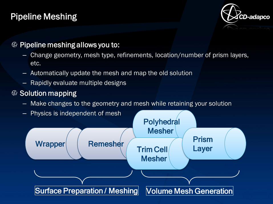
Pipeline meshing allows you to:
– Change geometry, mesh type, refinements, location/number of prism layers,
etc.
– Automatically update the mesh and map the old solution
– Rapidly evaluate multiple designs
Solution mapping
– Make changes to the geometry and mesh while retaining your solution
– Physics is independent of mesh
3
Wrapper Remesher
Polyhedral
Mesher
Surface Preparation / Meshing Volume Mesh Generation
Trim Cell
Mesher
Prism
Layer
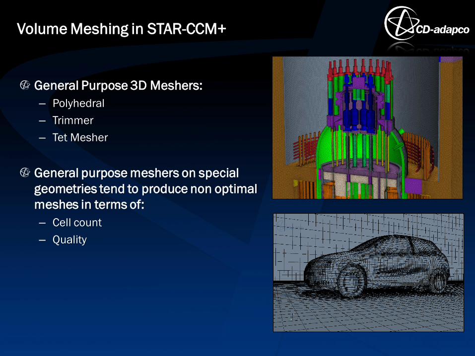
General Purpose 3D Meshers:
– Polyhedral
– Trimmer
– Tet Mesher
General purpose meshers on special
geometries tend to produce non optimal
meshes in terms of:
– Cell count
– Quality
Volume Meshing in STAR-CCM+
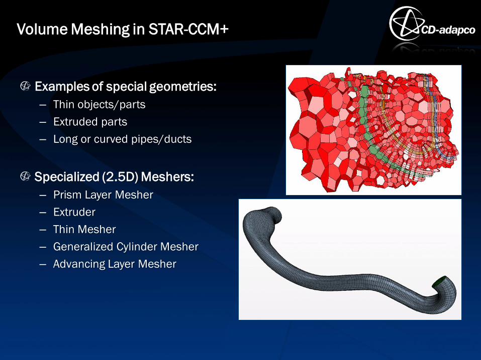
Examples of special geometries:
– Thin objects/parts
– Extruded parts
– Long or curved pipes/ducts
Specialized (2.5D) Meshers:
– Prism Layer Mesher
– Extruder
– Thin Mesher
– Generalized Cylinder Mesher
– Advancing Layer Mesher
Volume Meshing in STAR-CCM+

2.5D meshing is a synthetic definition of those meshing techniques that
exploit the fact that certain special geometries have a general mesh in 2
dimensions while in the 3rd dimension the mesh has some form of
simplification:
– Extruded in a predetermined direction
– Extruded along the local normal direction
– Swept along a 3d curve or axis
Volume Meshing in STAR-CCM+
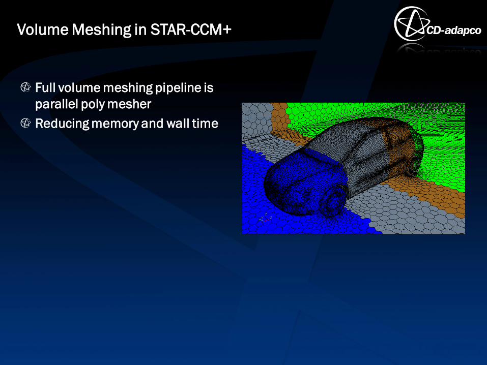
Full volume meshing pipeline is
parallel poly mesher
Reducing memory and wall time
Volume Meshing in STAR-CCM+
Golden rule of volume meshing in STAR-CCM+
Volume meshers have requirements for the input surface:
– Closed
– Manifold
– Non-intersecting
Often cell quality issues in the volume mesh can be tracked down to
face quality issues in the surface mesh
Recommendation is to use the Surface Remesher always prior to volume
meshing (with same size settings)
Volume Meshing
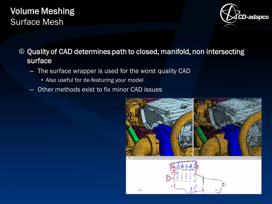
Quality of CAD determines path to closed, manifold, non intersecting
surface
– The surface wrapper is used for the worst quality CAD
• Also useful for de-featuring your model
– Other methods exist to fix minor CAD issues
Volume Meshing
Surface Mesh
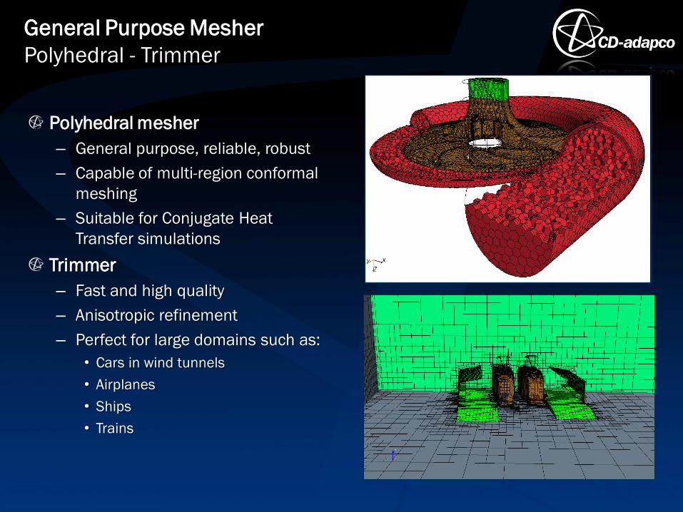
Polyhedral mesher
– General purpose, reliable, robust
– Capable of multi-region conformal
meshing
– Suitable for Conjugate Heat
Transfer simulations
Trimmer
– Fast and high quality
– Anisotropic refinement
– Perfect for large domains such as:
• Cars in wind tunnels
• Airplanes
• Ships
• Trains
General Purpose Mesher
Polyhedral - Trimmer
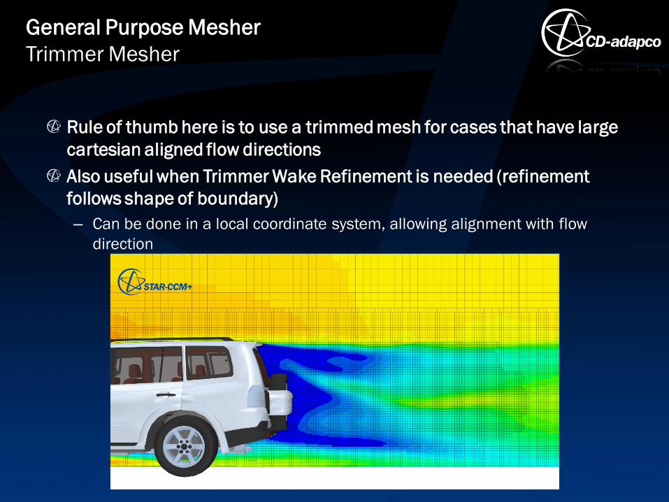
Rule of thumb here is to use a trimmed mesh for cases that have large
cartesian aligned flow directions
Also useful when Trimmer Wake Refinement is needed (refinement
follows shape of boundary)
– Can be done in a local coordinate system, allowing alignment with flow
direction
General Purpose Mesher
Trimmer Mesher
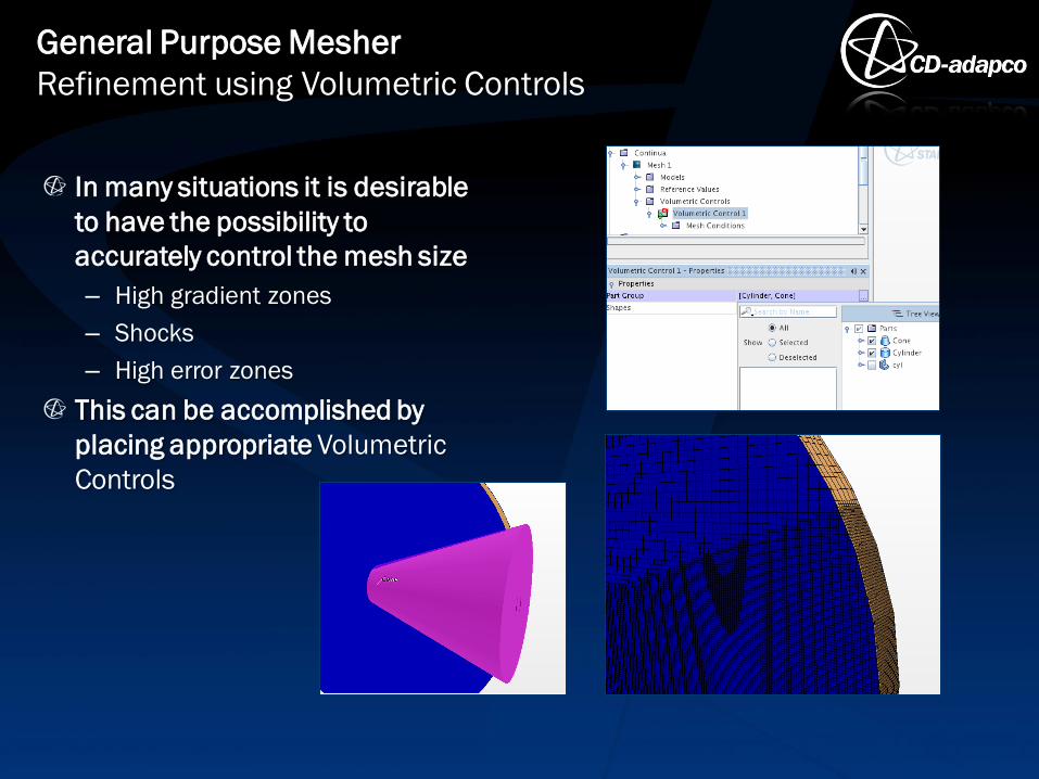
In many situations it is desirable
to have the possibility to
accurately control the mesh size
– High gradient zones
– Shocks
– High error zones
This can be accomplished by
placing appropriate Volumetric
Controls
General Purpose Mesher
Refinement using Volumetric Controls
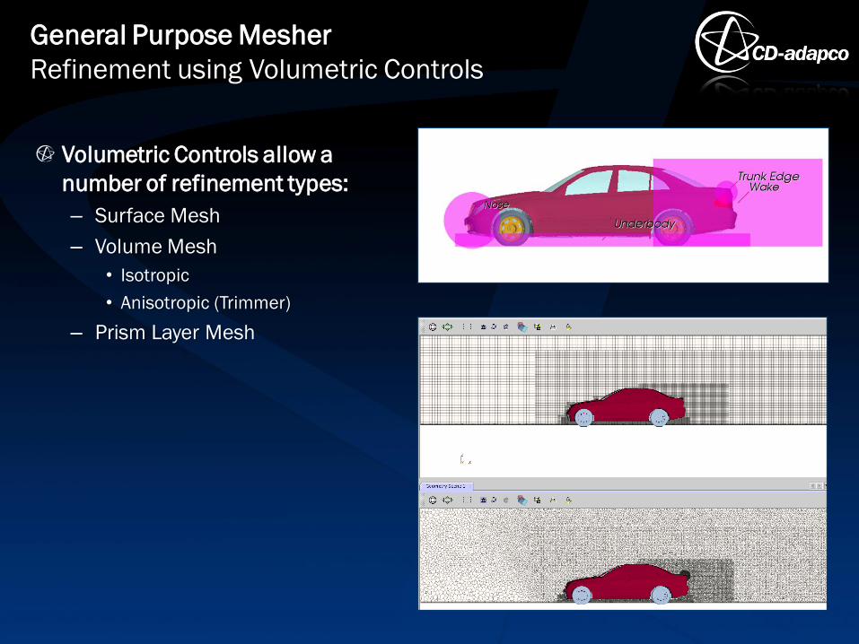
Volumetric Controls allow a
number of refinement types:
– Surface Mesh
– Volume Mesh
• Isotropic
• Anisotropic (Trimmer)
– Prism Layer Mesh
General Purpose Mesher
Refinement using Volumetric Controls
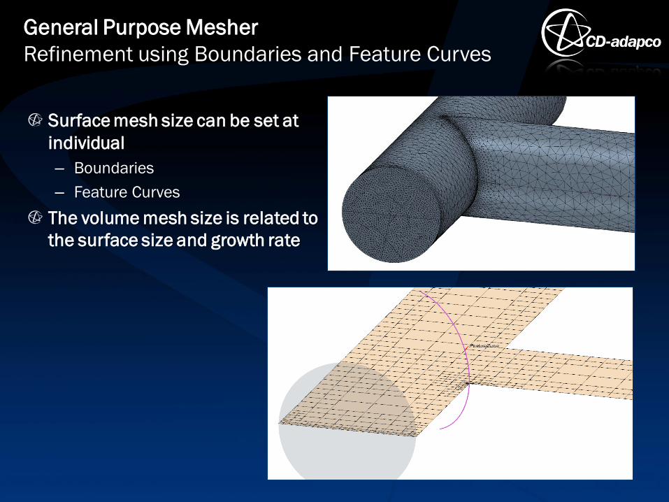
Surface mesh size can be set at
individual
– Boundaries
– Feature Curves
The volume mesh size is related to
the surface size and growth rate
General Purpose Mesher
Refinement using Boundaries and Feature Curves
Refinement levels provide a quick way to globally refine a polyhedral
mesh
– Activated within the Polyhedral Mesher model settings
– One of two refinement levels selected in Reference Values
• Level 1: Splits each polyhedral cell into 6 or 7 new cells
• Level 2: Splits each polyhedral cell into 40 to 50 new cells
• Prism Layer unchanged
General Purpose Mesher
Polyhedral Refinement Level
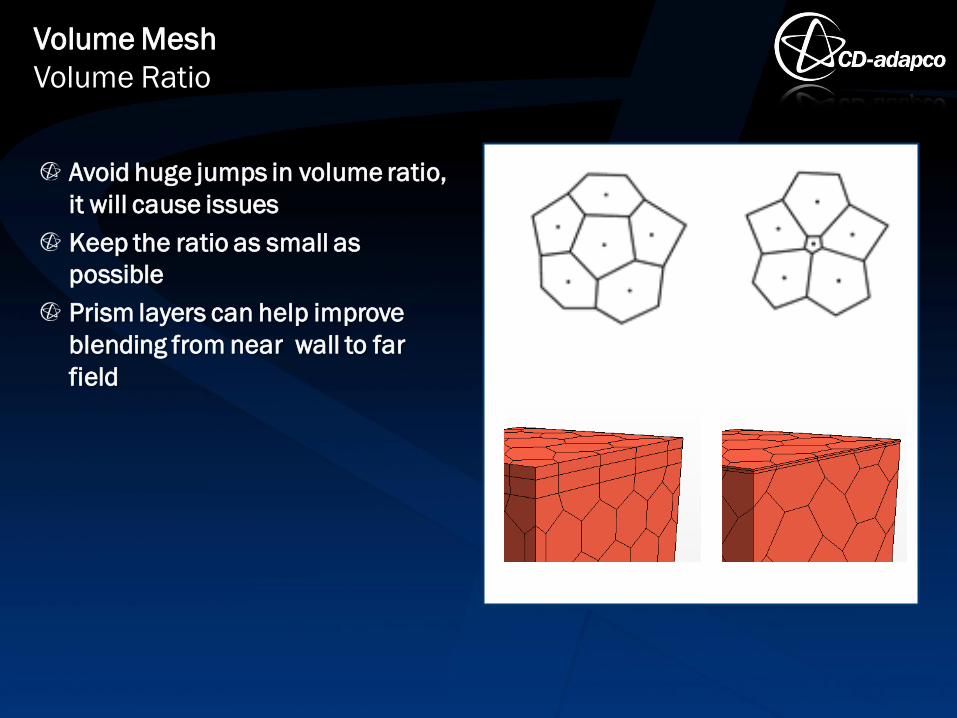
Avoid huge jumps in volume ratio,
it will cause issues
Keep the ratio as small as
possible
Prism layers can help improve
blending from near wall to far
field
Volume Mesh
Volume Ratio

The volume ratio for trimmed cells is influenced through different Growth
Rate values
On continuum level
– Trimmer > Properties: Template mesh growth rate
– Reference Values > Template Growth rate > Properties: Default Growth rate
Volume Mesh
Volume Ratio - Trimmer
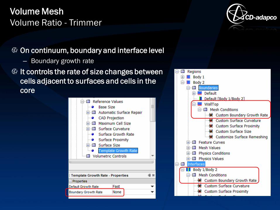
On continuum, boundary and interface level
– Boundary growth rate
It controls the rate of size changes between
cells adjacent to surfaces and cells in the
core
Volume Mesh
Volume Ratio - Trimmer
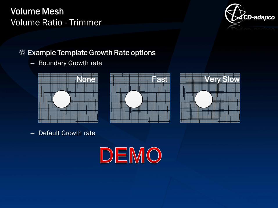
Example Template Growth Rate options
– Boundary Growth rate
– Default Growth rate
Volume Mesh
Volume Ratio - Trimmer
None Very Slow Fast
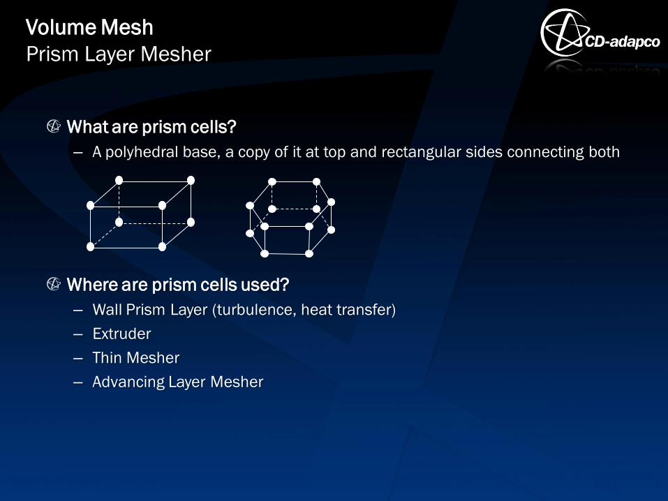
What are prism cells?
– A polyhedral base, a copy of it at top and rectangular sides connecting both
Where are prism cells used?
– Wall Prism Layer (turbulence, heat transfer)
– Extruder
– Thin Mesher
– Advancing Layer Mesher
Volume Mesh
Prism Layer Mesher
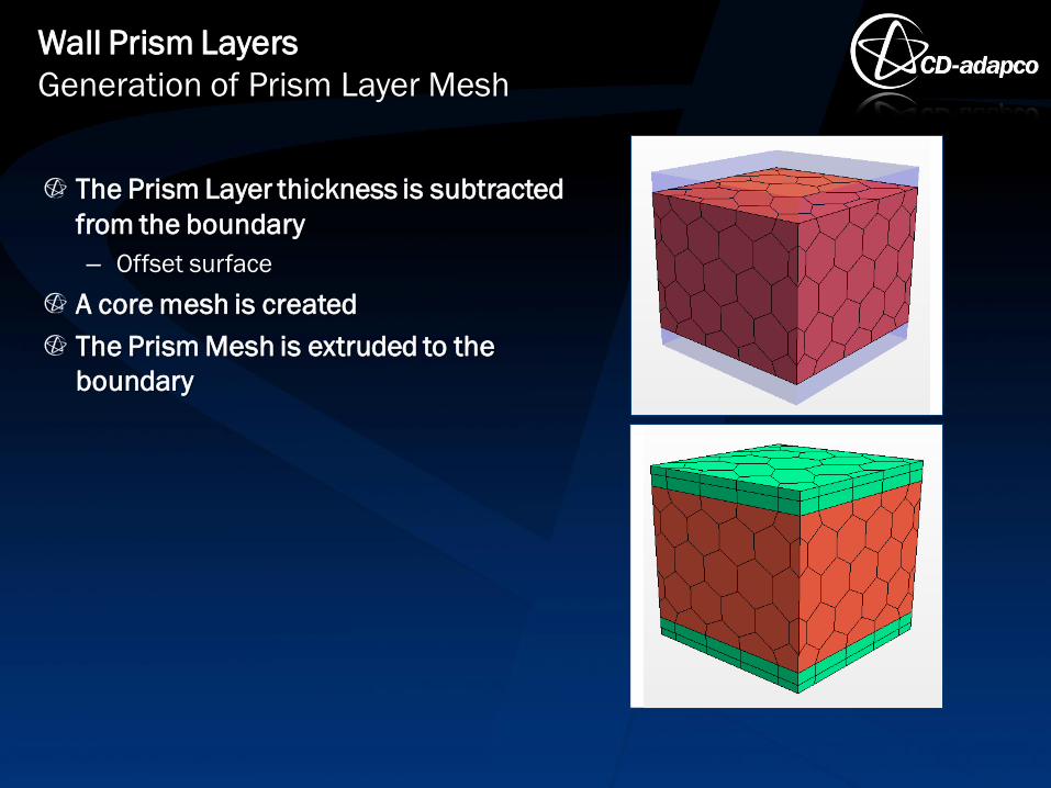
The Prism Layer thickness is subtracted
from the boundary
– Offset surface
A core mesh is created
The Prism Mesh is extruded to the
boundary
Wall Prism Layers
Generation of Prism Layer Mesh
Where are Prism Layers generated?
– Only at boundaries of type Wall
Why is no Prism Layer created at my fluid-solid interface?
– Although the boundaries forming an interface are often of type Wall, being an
interface overrules this setting: At an interface no prism layers will be
generated as default
Wall Prism Layers
Locations of Prism Mesh

With the recent releases of STAR-CCM+ the creation of boundary layers
has been further improved
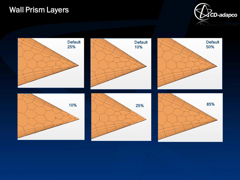
Today I will show you some of the Model Properties with which to
influence the prism mesh in narrow passages
– Gap Fill Percentage
– Minimum Thickness Percentage
– Layer Reduction Percentage
Wall Prism Layers
Introduction to Properties Options
Wall Prism Layers
Default
25%
10%
Default
10%
25%
Default
50%
85%
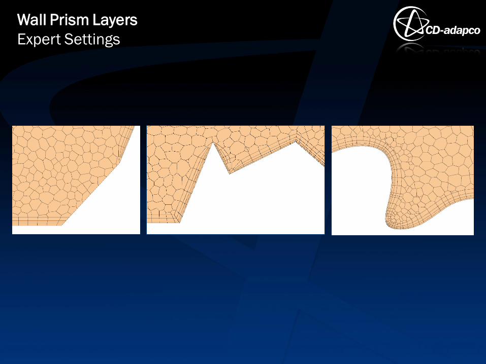
Wall Prism Layers
Expert Settings
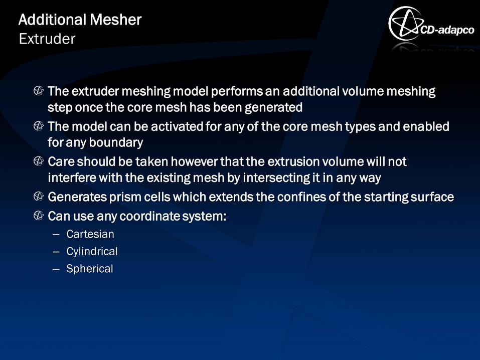
The extruder meshing model performs an additional volume meshing
step once the core mesh has been generated
The model can be activated for any of the core mesh types and enabled
for any boundary
Care should be taken however that the extrusion volume will not
interfere with the existing mesh by intersecting it in any way
Generates prism cells which extends the confines of the starting surface
Can use any coordinate system:
– Cartesian
– Cylindrical
– Spherical
Additional Mesher
Extruder

Extruder Mesher Options
– Frozen Boundaries
Additional Mesher
Extruder
Frozen
Boundaries
On
Frozen
Boundaries
Off
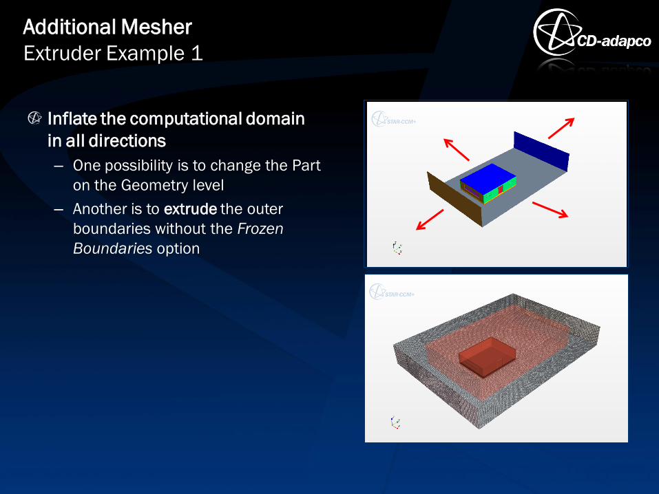
Inflate the computational domain
in all directions
– One possibility is to change the Part
on the Geometry level
– Another is to extrude the outer
boundaries without the Frozen
Boundaries option
Additional Mesher
Extruder Example 1
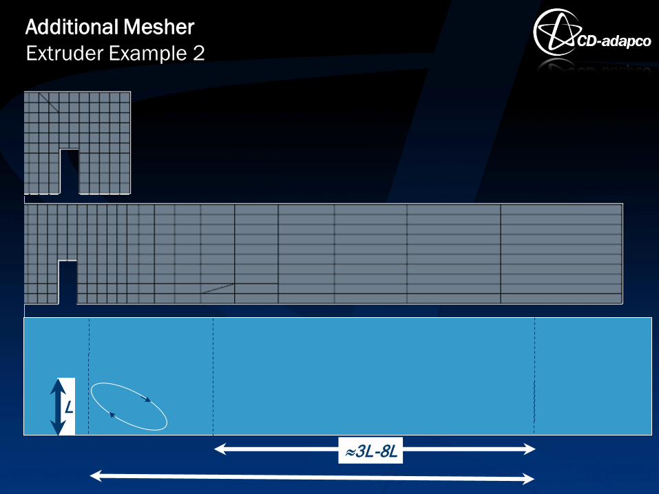
Additional Mesher
Extruder Example 2
3L-8L
L
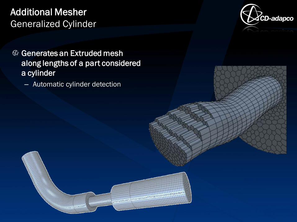
Generates an Extruded mesh
along lengths of a part considered
a cylinder
– Automatic cylinder detection
Additional Mesher
Generalized Cylinder
The thin meshing model allows thin regions in the geometry to have a
prismatic type volume mesh
Reason is to improve the overall cell quality and reduce the cell count
when compared to an equivalent tetrahedral or polyhedral type core
mesh
When very thin structures cannot be modeled using baffles – their
thickness must be modeled with a minimum of 3 cells through the
thickness
Advanced Mesher
Thin Mesher
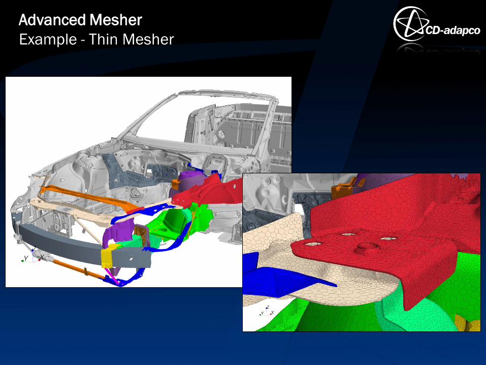
Advanced Mesher
Example - Thin Mesher
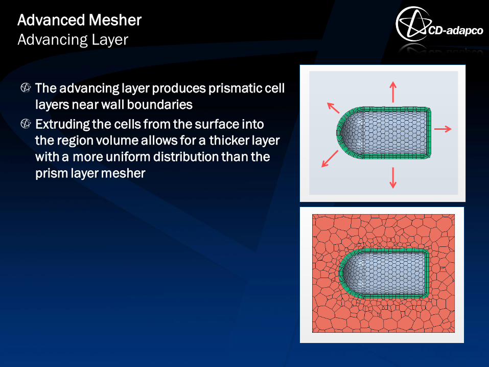
The advancing layer produces prismatic cell
layers near wall boundaries
Extruding the cells from the surface into
the region volume allows for a thicker layer
with a more uniform distribution than the
prism layer mesher
Advanced Mesher
Advancing Layer
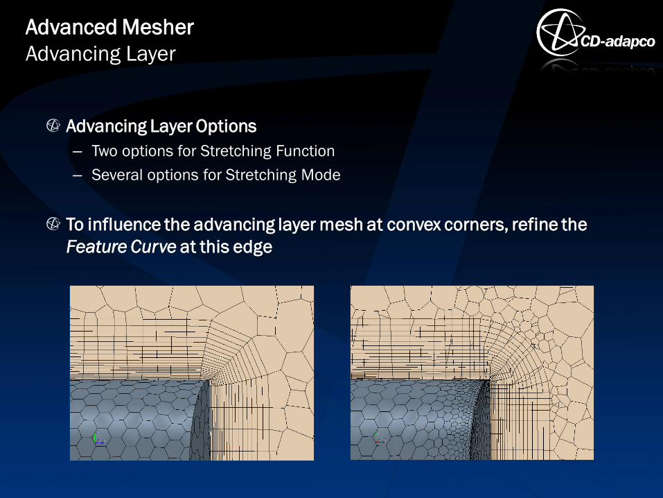
Advancing Layer Options
– Two options for Stretching Function
– Several options for Stretching Mode
To influence the advancing layer mesh at convex corners, refine the
Feature Curve at this edge
Advanced Mesher
Advancing Layer
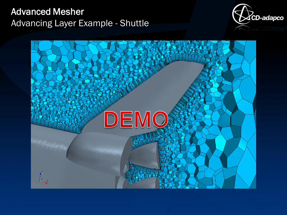
Advanced Mesher
Advancing Layer Example - Shuttle
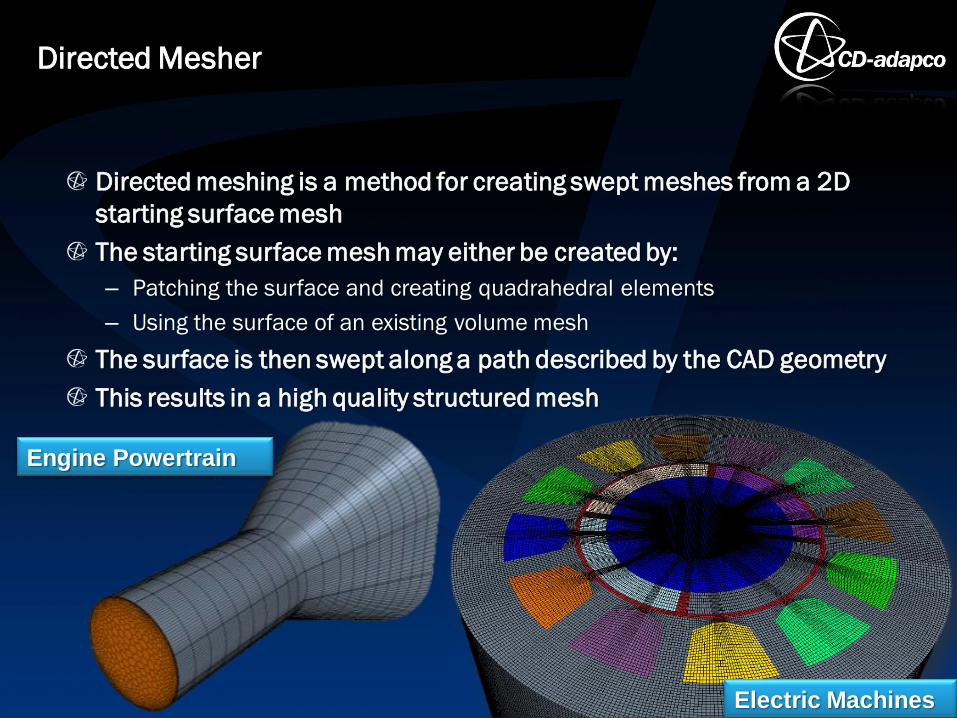
Directed meshing is a method for creating swept meshes from a 2D
starting surface mesh
The starting surface mesh may either be created by:
– Patching the surface and creating quadrahedral elements
– Using the surface of an existing volume mesh
The surface is then swept along a path described by the CAD geometry
This results in a high quality structured mesh
Directed Mesher
Electric Machines
Engine Powertrain
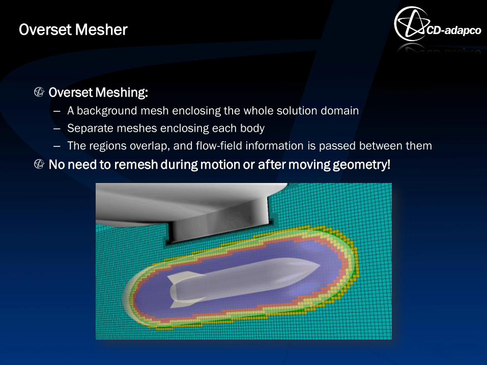
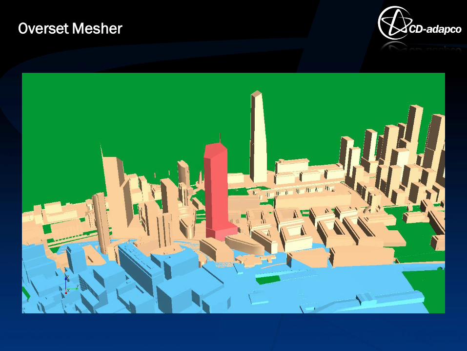
Overset Meshing:
– A background mesh enclosing the whole solution domain
– Separate meshes enclosing each body
– The regions overlap, and flow-field information is passed between them
No need to remesh during motion or after moving geometry!
Overset Mesher

Overset Mesher
Overset Mesher

Any Questions ?
Questions