betriebsanleitung operating manual - emod …...emod motoren gmbh elektromotorenfabrik zur kuppe 1...
TRANSCRIPT

EMOD Motoren GmbH
Elektromotorenfabrik Zur Kuppe 1 36364 Bad Salzschlirf DeutschlandFon: +49 6648 51-0 Fax: +49 6648 51-143 [email protected] www.emod-motoren.de
für Drehstrommotoren in Zündschutzart Erhöhte Sicherheit „eb“ und Einphasenmotoren in Zündschutzart Erhöhte Sicherheit „eb“ mit angebautem Kondensator „qb“
for three-phase motors in type of protection Increased Safety “eb” and single-phase motors in type of protection Increased Safety “eb” with capacitor in type of protection Powder filling “qb”
Betriebsanleitung Operating manual

Die EMOD-Baureihen
820EinphasenmotorenSchutzart IP 55 bis 2,5 kWSingle-phase motorsdegree of protection IP 55, up to 2.5 kW
821Drehstrommotoren IP 55in Norm- und Sonderausführungen bis 1700 kWThree-phase motors, IP 55in standard and special configurations, up to 1700 kW
821 / IEDrehstrommotoren IP 55IE2 + IE3 nach IEC 60034-30-1 Three-phase motors, IP 55IE2 + IE3 according to IEC 60034-30-1
822 Drehstrommotoren IP 23in Norm- und Sonder-ausführungen bis 1700 kWThree-phase motors, IP 23in standard and special configurations, up to 1700 kW
824 TopfmotorenSchutzart IP 67 bis 6 kWEncapsulated motorsdegree of protection IP 67, up to 6 kW
825 TauchmotorenSchutzart IP 68 bis 1700 kWSubmersible motorsdegree of protection IP 68, up to 1700 kW
826Fahr- und Hebezeugmotorenbis 32/2-polig und regelbarCrane and hoist drive motorswith pole switching up to 32/2 poles and variable speed
829Schiffsmotorenfür Unter- und Oberdeckaufstellung, mit oder ohne AbnahmeMarine motorsfor on-deck and below-deck applications, with and without certification
831GleichstrommotorenSchutzart IP 44DC motorsdegree of protection IP 44
835Drehstrom-Servomotorenmit hohem StillstandsmomentAC servomotorswith increased standstill torques
836Drehstrom-SchleifringläufermotorenSchutzart IP 55Wound-rotor induction motorsdegree of protection IP 55
Explosionsgeschützte MotorenExplosion-proof motors
837Wassergekühlte Drehstrommotoren Leistungsbereich 0,75 bis 1700 kWWater-cooled three-phase motorsrated outputs 0.75 kW to 1700 kW
838 FlachmotorenDrehzahlen bis 24.000 U/minFlat motorsrated speeds up to 24,000 rpm
PermanenterregteSynchronmotorenin höchsten EffizienzklassenPermanent-magnetthree-phase motorsin highest efficiency classes
The EMOD product range
Ob wassergekühlt oder explosionsgeschützt – bei EMOD gibt es für jeden Einsatz den passenden Antrieb. Die verschiedenen Baureihen im Überblick:
Whether water-cooled or explosion-proof –EMOD has the right drive for every application. A quick look at the various ranges:

3
Die treibende Kraft ! The driving force !
Ausgabe 08/2018 Art.-Nr.: 118628 / Ident.-Nr.: K.51.821.101
Drehstrommotoren in Zündschutzart Erhöhte Sicherheit „eb“
Einphasenmotoren in Zündschutzart Erhöhte Sicherheit „eb“ mit Kondensator in Sandkapselung „qb“
nach EN 60079-0 : 2012 + A11:2013 EN 60079-7 : 2015 + A1:2018 EN 60079-5 : 2015
gemäß Richtlinie 2014 / 34 / EU (ATEX)
Baugrößen 56 bis 225
Typenreihe: EeEA 56 … EeDA 56 – 112 … EeDG 90 – 225 …
Edition 08/2018 Art.-no.: 118628 / Ident.-no.: K.51.821.101
Three-phase motors in type of protection Increased Safety “eb”
Single-phase motors in type of protection Increased Safety “eb” with capacitor in type of protection Powder Filling “qb”
according EN 60079-0 : 2012 + A11:2013 EN 60079-7 : 2015 + A1:2018 EN 60079-5 : 2015
and Directive 2014 / 34 / EU (ATEX)
Frame sizes 56 to 225
Type series: EeEA 56 … EeDA 56 – 112 … EeDG 90 – 225 …
Alle Rechte vorbehalten ! All rights reserved !
Ex-Kennzeichnung:Ex-marking
0123 II 2G Ex eb IIC T1, T2, T3 oder/or T4 Gb
0123 II 2G Ex eb qb IIC T1, T2, T3 oder/or T4 Gb

4
Achtung
Die in dieser Betriebsanleitung enthaltenen Sicherheitshinweise sind unbedingt zu beachten!
Sonderausführungen und Bauvarianten können in technischen Details von der Grund- type abweichen. Bei eventuell auftretenden Unklarheiten wird dringend empfohlen sich mit der EMOD Motoren GmbH in Verbindung zu setzen. Hierbei grundsätzlich Motortype und Motornummer angeben.
1. Allgemeine Hinweise
1.1 Anwendungsbereich
Die Motoren können entsprechend der auf dem Leistungsschild gestempelten Schutz- art, der vom Hersteller vorgesehenen Bau-form laut Katalog oder den Angaben des Kunden eingesetzt werden. Beim Einsatz von Sondermotoren gelten zusätzlich die Anga-ben in Angebot und Auftragsbestätigung.
1.2 Sicherheit
Warnung
Die Aufstellung, Inbetriebnahme und War-tung darf nur von qualifiziertem, auf Grund seiner Ausbildung und Erfahrung geeigne-tem Personal durchgeführt werden.
Hierbei sind besonders zu beachten: – die technischen Daten und Angaben über
die zulässige Verwendung (Inbetriebnah-me-, Umgebungs- und Betriebsbedingun-gen) die u. a. im Katalog, der Betriebsanlei-tung, den Schildangaben und der übrigen Produktdokumentation enthalten sind,
– die einschlägigen Errichtungs- und Unfallverhütungsvorschriften,
– der fachgerechte Einsatz von Werkzeugen, Hebe- und Transporteinrichtungen,
– das Anbringen eines Berührungsschutzes im eingebauten Zustand bei Gefährdung von Personen durch bewegliche Teile,
– die Benutzung persönlicher Schutzaus- rüstung.
1.3 Hinweise
1.3.1 Explosionsgefährdete BereicheWelcher Bereich im Freien oder in geschlos-senen Räumen als explosionsgefährdet im Sinn der allgemeinen Verordungen und Be stim mungen zu betrachten ist, muss aus schließlich dem Betreiber oder, wenn Zweifel über die Festlegung besteht, der zuständigen Aufsichts behörde überlassen werden. Motoren in erhöhter Sicherheit entsprechen in ihrer Bauweise EN 60034 sowie den Normen und Vorschriften nach EN 60079-0, EN 60079-7 und EN 60079-5. Sie sind für die Verwendung in Bereichen bestimmt, in denen unter den nachfolgend aufgeführten Bedingungen des Normal-klimas durch Vermischung von Luft mit Gasen, Dämpfen oder Nebeln eine Explosions gefährdung hervorgerufen wird: – Temperatur − 20 °C bis + 60 °C,– Druck 0,8 bar bis 1,1 bar und– Luft mit normalem Sauerstoffgehalt,
üblicherweise 21 %. Zündschutzart und die Temperaturklasse sind auf dem Leistungsschild / Zusatzschild bzw. in der EG / EU-Baumusterprüfbescheinigung und dem dazugehörigen Datenblatt angegeben.
1.3.2 Gerätegruppe II Kategorie 2G (EPL Gb)In diese Kategorie fallen elektrische Maschi-nen der Zündschutzart Erhöhte Sicherheit „eb“mit / ohne angebautem Kondensator in Zündschutzart Sandkapselung „qb“. Sie dürfen in die Zone 1 und Zone 2 einge-bracht werden (siehe Tabelle).
Zone 0 Zone 1 Zone 2
Kategorie 1G
Kategorie 1G + 2G
Kategorie 1G + 2G + 3G
EPL Ga EPL G a+ Gb EPL Ga + Gb + GcEPL = Equipment Protection Level

5
Achtung:Motoren in Zündschutzart Erhöhter Sicher-heit „eb“ dürfen nur an einem Frequenz-umrichter betrieben werden, wenn eine gemeinsame Baumusterprüfbescheinigung (Motor – Fre quenz umrichter) vorliegt.
2. Transport und Lagerung
2.1 Transport
Warnung
Beim Transport der komplett montierten Antriebseinheit nur die dafür vorgesehenen Hebeösen benutzen. Komplette Antriebseinheiten nicht an den Motor-Transportösen anheben.
Die Motoren sind nach Eingang auf Trans-portschäden zu prüfen.Eventuell vorhandene Schäden grundsätzlich schriftlich aufnehmen.
2.2 Lagerung
Der Lagerort sollte nach Möglichkeit tro-cken, sauber, temperaturkonstant und erschütterungsfrei sein.Damit der Schmierfilm in der Motorlage-rung und den Dichtungssystemen nicht ab-reißt, sollte bei längerer Einlagerungszeit die Motorwelle von Hand, z. B. in monat-lichen Abständen, um einige Umdrehungen gedreht werden.Die Wälzlager der Motoren sollten neu gefettet bzw. erneuert werden, wenn der Zeitraum zwischen Lieferung und Inbetrieb-nahme mehr als 4 Jahre beträgt. Bei ungüns-tigen Lagerungsbedingungen verringert sich dieser Zeitraum erheblich.
2.3 Überprüfen des Isolationswiderstandes
Warnung
Bei der Messung des Isolationswiderstandes und unmittelbar danach haben die Klem-men teilweise gefährliche Spannungen und dürfen nicht berührt werden!Bei Ex-Motoren müssen die Anschluss- klemmen nach der Messung sofort entladen werden, um Funkenentladungen zu vermeiden. Vor Inbetriebnahme des Motors, nach längerer Lagerungsdauer oder Stillstandzeit (mehr als 6 Monate), muss der Isolations-widerstand der Wicklung ermittelt werden. Wicklung mittels Isolationsmessgerät (max. Gleichspannung 500 V) gegen Masse prüfen.Ist der Mindest-Isolationswiderstand bei einer Wicklungstemperatur von 25 °C kleiner als 30 MΩ oder bei einer Wicklungstempe-ratur von 75 °C kleiner als 1 MΩ, muss die Motorwicklung getrocknet werden bis der erforderliche Mindestisolationswiderstand erreicht ist. Die Wicklungstemperatur darf hierbei 80 °C nicht überschreiten!Damit bei geschlossenen Motoren ein Luftaustausch erfolgen kann, Lagerschild lösen. Bei Trocknung der Wicklung durch Anschluss an Niederspannung sind Anweisungen des Herstellers einzuholen.Nach einem Austrocknen der Wicklung ist eine Wartung der Lager erforderlich (siehe entsprechendes Kapitel!).

6
3. Montage und Inbetriebnahme
Warnung
Alle Arbeiten am Motor nur im elektrisch spannungslosen Zustand durchführen!
3.1 Aufstellung
3.1.1 StandortDie Motoren sollen leicht zugänglich, bei Umgebungs- bzw. Kühlmitteltemperaturen von − 20 °C bis 40 °C aufgestellt bzw. ange-baut werden. Nach Rücksprache mit dem Hersteller sind auch Sonderausführungen mit Umgebungs- bzw. Kühlmitteltempera-turen von − 40 °C bis 65 °C möglich. Vom Standard abweichende Umgebungs- bzw. Kühlmitteltemperaturen werden auf dem Typenschild gesondert ausgewiesen.Die Kühlluft muss ungehindert zu- und ab strömen können und darf nicht unmittel-bar wieder angesaugt werden. Die Luft ein- und -austrittssöffnungen sowie die Kanäle zwischen den Kühlrippen sind von Ver-schmutzung freizuhalten.Die Motorenreihe ist unter anderem auch für den Anbau an bzw. Einbau in Arbeits-maschinen vorgesehen.Deren eingebrachte zusätzliche Erwärmung (z. Bsp. durch Flanschmontage) muss bei der Montage berücksichtigt werden. Ohne zusätzliche thermische Prüfung durch den Hersteller darf die Oberflächentemperatur der angebauten Maschinen 40 °C nicht überschreiten.
3.1.2 Aufstellung mit Wellenende nach unten
Bei Aufstellung mit Wellenende nach oben und unten muss gewährleistet sein, dass in das obere Lager kein Wasser eindringen kann. Bei senkrechter Anordnung der Moto-ren mit dem Wellenende nach unten, z. B. Bauformen IM V5, IM V1 und IM V18, wird das Hineinfallen von Fremdkörpern in die Motorlüfterhaube durch ein serienmäßiges Schutzdach verhindert. Der Kühlluftstrom wird durch die Abdeckung nicht behindert.
3.2 Befestigung von Motoren
Fußmotoren müssen auf ebener, erschütte-rungsfreier Auflagefläche aufgestellt und befestigt werden. Alle Befestigungsfüße müssen planflächig aufliegen, gegebenen-falls zum Ausgleich dünne Bleche unterlegen.Bei Flanschmotoren ist auf Planlauf des Gegenflansches zu achten. Planlauffehler können zu Lagerschäden bzw. zum Ausfall von Dichtungssystemen führen.
3.3 Kondenswasser-Abflusslöcher
Es ist darauf zu achten, dass vorhandene Kondenswasser-Abflusslöcher nach der Montage an der tiefsten Stelle des Motors liegen und von Verunreinigungen freige-halten werden. Verschlossene Kondenswasser-Abflusslöcher (wenn vorhanden) sind von Zeit zu Zeit zu öffnen und vor jeder Inbetriebnahme wieder zu verschliessen.
Für Ex-Motoren müssen die Kondens- wasserabflusslöcher generell verschlossen sein, damit die angegebene IP-Schutzart erhalten bleibt.Achtung:Müssen diese Bohrungen während des Betrie-bes offen bleiben, so muss der Nachweis er bracht werden, dass die IP-Schutzart auf-recht erhalten bleibt.
3.4 Auswuchtung
Warnung
Wird ein Motor ohne Antriebselement in Betrieb genommen, so ist die Passfeder gegen Herausschleudern zu sichern.Maßnahmen zum Berührungsschutz bei rotierenden Bauteilen beachten!
Die Motorwellen sind am Wellenspiegel ent-sprechend DIN ISO 8821 mit der Auswucht-art gekennzeichnet:Auswuchtung mit halber Passfeder „H“Auswuchtung mit voller Passfeder „F“Bei Montage des Abtriebselementes auf entsprechende Auswuchtart achten!

7
3.5 Elektrischer Anschluss
Netzspannung und -frequenz müssen mit den Daten auf dem Leistungsschild über-einstimmen. Spannungsabweichungen von± 5 % und / oder Frequenzabweichungen von ± 2 % sind wie im Bereich A nach EN 60034-1 beschrieben zulässig. Wir bitten Sie dies beim Anschluss der Motoren zu beachten.
Jedem Motor wird bei Auslieferung ein Anschlussplan beigelegt. Der Anschluss des Motors und der Steuerung sowie des Überlastungsschutzes und der Erdung sind nach den VDE- und Installationsvorschriften sowie den Bestimmungen der EVU’s vorzu-nehmen.
Die Drehrichtung des abtriebseitigen Wellenendes ist vor der Inbetriebnahme zu überprüfen. Die Umkehr der Drehrichtung ist durch Vertauschen von zwei beliebigen Spannungsphasen möglich.
Die zur Zugentlastung oder als Verdreh-schutz für die Zuleitungen vorgesehenen Einführungsteile sind ordnungsgemäß anzuwenden. Nicht benötigte Einführungs-öffnungen müssen zur Aufrechterhaltung der IP-Schutz art mit bescheingten Stopfen bzw. Kabel- und Leitungseinführungen (KLE) nach Richtlinie 2014 / 34 / EU verschlossen sein. Im Auslieferzustand werden die Ex-Motoren ohne Kabelverschraubung geliefert, alle metrischen Kabeleinführungen werden mit nach Richtlinie 2014 / 34 / EU bescheinigten Verschlussstopfen versehen. Beim Anschluss des Motors ist darauf zu achten, dass nur nach Richtlinie 2014 / 34 / EU bescheinigte Kabel- und Leitungseinführun-gen verwendet und die Vorgaben des Her-stellers beachtet werden. Es ist sicher zu
stellen, dass die Schutzart des Motors unbe-dingt erhalten bleibt (siehe Typenschild). Bei Anschluss des Motors sind die Vor-schriften für das Errichten von elektrischen Anlagen in explosionsgefährdeten Bereichen nach Norm EN 60079-14 zu berücksichtigen (z. B. automatisches Wiedereinschalten nach Motorstillstand).
3.6 Inbetriebnahme
Warnung
Vorsicht Verbrennungsgefahr!An der Motoroberfläche können hohe Temperaturen von über 80 °C auftreten. Bei Bedarf Berührungsschutz vorsehen!
3.6.1 Montage der Übertragungselemente Zum Auf- und Abziehen der Übertragungs-elemente nur geeignete Werkzeuge und Vorrichtungen verwenden. Auf die Motor-lagerung darf kein Druck oder Schlag über-tragen werden.
3.6.2 Ausrichten bei KupplungsbetriebBei Kupplungsbetrieb sind die Wellen axial und radial gegeneinander auszurichten. Das Einstellen der Luft zwischen den Kupp-lungshälften ist nach den Angaben der Kupplungshersteller vorzunehmen.Nur Kupplungen verwenden, die mittenver-satz-, winkel-, längs- und drehelastisch sind. Starre Kupplungen sind nicht zulässig und nur in Ausnahmefällen nach Absprache mit dem Hersteller einsetzbar.Wird die Übertragung über Riemen herge-stellt, muss beachtet werden, dass dieser keine elektrostatische Ladung aufnehmen kann.
Baugröße Leitungseinführungen Anschluss max. anschließbarer Leiter
56 – 71 2 × M16 × 1,5 o. 2 × M20 × 1,5 6 × M4 2,5 / 4,0 mm² mehrdrähtig / eindrähtig
80 – 112 2 × M25 × 1,5 6 × M4 4,0 / 6,0 mm² mehrdrähtig / eindrähtig
112 – 132 2 × M25 × 1,5 + 1 × M16 × 1,5 6 × M4 4,0 / 6,0 mm² mehrdrähtig / eindrähtig
160 – 180 2 × M40 × 1,5 + 1 × M16 × 1,5 6 × M5 10 / 16 mm² mehrdrähtig / eindrähtig
200 – 225 2 × M50 × 1,5 + 1 × M16 × 1,5 6 × M6 25 / 35 mm² mehrdrähtig / eindrähtig

8
3.6.3 Vor Inbetriebnahme ist mindestens zu prüfen ob:
– der Läufer ohne Anzustreifen gedreht werden kann,
– der Motor ordnungsgemäß ausgerichtet und montiert ist,
– die Abtriebselemente richtige Einstell-bedingungen haben,
– alle elektrischen Anschlüsse, Verbindungs-elemente sowie Befestigungsschrauben ordnungsgemäß angezogen und ausge-führt sind,
– vorhandene Zusatzeinrichtungen (z. B. Bremse) funktionsfähig sind,
– die Kühlmittelzuführung nicht beein-trächtigt ist,
– Berührungsschutzmaßnahmen für bewegte und spannungsführende Teile getroffen sind.
3.6.4 Maximale Oberflächentemperaturen nach VDMA/ ZVEI 24263:2011-02
Temperaturklasse T3
Polpaarzahlmax. Wellen-temperatur
max. Flansch-temperatur
2-polig 60 °C 60 °C
4-polig 75 °C 75 °C
Rahmenbedingungen:– maximal am Wellenende und Motor-
flansch zulässige Temperaturen– kein Umrichterbetrieb– eigenbelüftet– Baugröße 63 bis 200– Motoren gemäß DIN EN 50347– Umgebungstemperatur − 20 °C bis + 40 °C
4. Instandhaltung
Warnung
Alle Arbeiten am Motor nur im abgeschalte-ten, gegen Wiedereinschalten gesicherten Zustand durchführen!
Neben den Hauptstromkreisen ist auch auf eventuell vorhandene Zusatz- oder Hilfs-stromkreise zu achten!
4.1 Inspektion
Je nach Schmutzbefall sind die Motoren regelmäßig entlang der gesamten Ober-fläche, z. B. mit trockener Druckluft, zu säubern.
Erste Inspektion im Normalfall nach ca. 500 Betriebsstunden, spätestens nach 1 Jahr durchführen. Weitere Folgeinspektionen sollten je nach Einsatzbedingungen in ge-eigneten Intervallen, wie z. B. Nachschmier- bzw. Fettwechselfristen, mindestens jedoch einmal im Jahr durchgeführt werden.
Bei Inspektionen ist zu prüfen, dass– die technischen Daten laut Typenschild
eingehalten werden,– keine Leckagen (Öle, Fette, Wasser)
vorhanden sind,– sich die Laufgeräusche der Lager
sowie die Laufruhe des Motors nicht verschlechtert haben,
– alle Befestigungsschrauben für elektrische und mechanische Verbindungen fest angezogen sind,
– bei Kupplungsbetrieb die Ausrichtung des Motors in den zulässigen Toleranzen liegt.
4.2 Lager
4.2.1 Lager mit DauerschmierungDie Lager der Motoren mit Fettdauer schmie-rung sind unter normalen Betriebs bedin-gung en 10 000 bis 20 000 Betriebs stunden, längs tens jedoch 3 Jahre wartungs frei.Bei Motoren mit zwei Deckscheiben als Lagerabdichtung (2Z-Lager) und einer Drehzahl bis 3 600 min−1 sollten die Lager nach 20 000 Betriebsstunden, spätestens nach 3 Jahren erneuert werden.
Bei Motoren mit einer Deckscheibe (Z-Lager) oder einem Lagerabschlussdeckel als Lagerabdichtung sollte– bei Drehzahlen bis 1 800 min−1
nach 20 000 Betriebsstunden,– bei Drehzahlen bis 3 600 min−1
nach 10 000 Betriebsstunden,spätestens jedoch nach 3 Jahren das Fett und wenn erforderlich die Lagerung erneuert werden.

9
4.2.2 Lager mit NachschmierungBei Motoren mit Nachschmiereinrichtung sind Nachschmierfrist, genaue Fettmenge und Fettqualität durch ein Zusatzschild am Motor angegeben. Falls die im Schmier-schild genannten Betriebsstunden innerhalb von 3 Jahren nicht erreicht werden, sollte vorzeitig nachgeschmiert werden. Nach-schmieren nur bei drehendem Läufer, damit sich das neue Fett im Lager verteilt !
Richtwerte zur Standardbefettung
Baugröße Fettmenge je Standard-lager
Baugröße Fettmenge je Standard-lager
90 3 g 160 10 g
100 4 g 180 14 g
112 6 g 200 18 g
132 8 g 225 18 g
Warnung
Das Mischen verschiedener Fettsorten ist zu vermeiden!
4.3 Instandsetzung
Ersatzteillisten und normale zeichnerische Darstellungen enthalten keine detaillierten Angaben über Art und Abmessungen der Bauteile. Deshalb beim Demontieren Zuord-nung der jeweiligen Bauteile feststellen und diese für den Zusammenbau kennzeichnen.
4.3.1 LagerwechselMotor im erforderlichen Umfang demontie-ren. Wälzlager mit geeigneter Vorrichtung abziehen und Lagerstellen von Verunreini-gungen säubern !Neues Wälzlager gleichmäßig auf ca. 80 °C erwärmen und aufziehen. Ca. 50 % des frei-en Raumes im Lager sowie der Fetträume im Lagerschild bzw. Lagerdeckel mit Fett der zugelassenen Qualitäten füllen.Dichtungselemente (z. B. Wellendichtringe) müssen vor dem Zusammenbau auf Funk-tion sowie Beschädigung überprüft und bei nicht mehr ausreichender Wirksamkeit erneuert werden.
5. Zusatzhinweise für Bremsmotoren
Warnung
Nach dem Anbau der Motoren ist die Bremse auf einwandfreie Funktion zu überprüfen!
5.1 Allgemeines
Die angebaute Bremse ist eine Sicherheits-bremse, die bei abgeschalteter Spannung durch Federkraft bremst. Gelüftet wird die Bremse über einen Elektromagneten.
5.2 Schaltung und Anschluss
Der Anschluss des Bremssystems erfolgt an einem separaten Klemmenkasten der ange-bauten Bremse, entsprechend dem jeweils beigefügten Schaltbild oder im Motorklem-menkasten. Die anzulegende Anschluss-spannung ist auf einem an der Bremse angebrachten Zusatzschild angegeben.
Warnung:Der Motor darf nicht gegen die geschlossene Bremse anlaufen!Schaltung so ausführen, dass zuerst die Bremse gelüftet und dann erst der Motor eingeschaltet wird.Bremsgrößen und Motorgrößen sind auf- einander abgestimmt. Diese Abstimmung darf nicht ohne Zustimmung vom Motor-hersteller geändert werden. Baumuster-prüfbescheinigung und Betriebsanleitung der Federdruckbremse sind beigefügt.
5.3 Wartung
Die angebauten Federdruck-Einscheiben-bremsen sind bis auf das Auswechseln der Reibscheibe bei Verschleißende und die Überprüfung des elektrischen Sicherheits-stranges (Mikroschalter und Thermoschalter) nahezu wartungsfrei. Beim Überschreiten des maximalen Luft spaltes wächst die

10
Ansprechzeit der Bremse stark an bzw. die Bremse lüftet bei ungünstigen Spannungs-verhältnissen nicht mehr. Der Wartungs-zyklus zur Überprüfung der Bremse ist in den Wartungs zyklus zur Überprüfung des Motors ein zubinden.
5.4 Rücklaufsperren und Rollenfreiläufe als Option
Bei Einbau von Rücklaufsperren und Rollen-freiläufen ist auf die Drehrichtung zu achten. Die Drehrichtung ist durch einen Pfeil am Motor gekennzeichnet.
5.5 Stillstandheizung
Die Motoren können wahlweise mit einer selbstlimitierenden Stillstandheizung gelie-fert werden. Beim Anschluss ist darauf zu achten, dass die Stillstandheizung nur bei nicht eingeschaltetem Motor in Betrieb ist, da sonst durch das Einbringen der zusätz- lichen Wärme die bescheinigte Temperatur-klasse überschritten werden kann.
6. Betriebsarten
Die Motoren dürfen, sofern nicht anders bescheinigt, nur für Dauerbetrieb (S1) und normale, nicht häufig wiederkehrende Anläufe, bei denen keine wesentliche Anlauferwärmung auftritt, eingesetzt wer-den. Sollen Motoren der Zündschutzart „eb“ für Schweranlauf > 1,7 × tE zum Einsatz kommen, sind sie entsprechend den Anga-ben der EG / EU-Baumusterprüfbescheinigung durch eine Anlaufüberwachung zu schützen.
6.1.1 Motorschutz mit stromabhängig verzögerter Schutzeinrichtung
Die Motoren sind gegen unzulässige Erwär-mung infolge Überlastung durch Bimetall- Motorschutzschalter allpolig zu schützen. Es müssen außerdem Vorkehrungen getroffen sein, damit der Betrieb eines Drehstrom-motores bei Ausfall einer Phase verhindert wird. Diese Schutzeinrichtungen müssen so beschaffen sein, dass sie den Nennstrom
überwachen sowie innerhalb der Zeit tE den festgebremsten Motor abschalten. Hierzu müssen für die zugehörigen Auslöser oder Relais Auslösekennlinien vorliegen, die die Auslösezeit als Funktion des Anzugstrom-verhältnises IA / IN darstellen. Die Kennlinien sollen die Auslösezeiten, ausgehend vom kalten Zustand bei einer Umgebungstempe-ratur von 20 °C in Abhängigkeit mindestens vom 3- bis 8-fachen Nennstrom darstellen. Die Schutzeinrichtungen müssen die ange-gebenen Auslösezeiten mit einer Toleranz von ± 20 % einhalten.Bei der Auswahl des stromabhängigen Aus-lösegerätes ist darauf zu achten, dass dieses eine Phasenausfallerkennung und eine Un-sym metrieerkennung hat. Es wird empfohlen ein nach Richtlinie 2014 / 34 / EU bescheinigtes Auslösegerät zu verwenden.Bei polumschaltbaren Motoren ist zu beach-ten, dass für jede Drehzahl eine Schutzein-richtung gegen Überlastung vorzusehen ist. Die Schutzschalter sind so zu verriegeln, dass beim Ansprechen eines Schalters nicht auf eine andere Drehzahl umgeschaltet werden kann.
6.1.2 Motorschutz mit KaltleiterMotoren der Zündschutzart erhöhte Sicher-heit „eb“, die für den Betrieb am Frequenz-umrichter bescheinigt sind, dürfen nur inner -halb der festgelegten Grenzwerte laut Daten blatt bzw. Typenschild betrieben werden. Dies bedeutet insbesondere die Überwachung des Dauerstroms in Abhän-gigkeit der Frequenz. Es dürfen nur Frequenzumrichter eingesetzt werden, die den in der Baumusterprüfbe-scheinigung genannten Anforderungen genügen.Die Auswertung der eingebauten Kaltleiter hat über eine den Anforderungen der Richt-linie 2014 / 34 / EU entsprechende Auslöse-einheit mit der Ex-Kennzeichnung II (2) G zu erfolgen.Die angegebene Drehzahl bzw. Frequenz darf in keinem Fall überschritten werden. Die max. zulässige Impulsspannung darf die Angabe im Datenblatt nicht überschreiten. Gegebenenfalls ist die Verwendung von Filtern oder Drosseln zwischen Umrichter und Motor notwendig.

11
Weiterhin ist sicherzustellen, dass die an-liegende Motorspannung mit der Angabe auf dem Typschild übereinstimmt (Span-nungsabfall der Anschlussleitung und ggf. von Filtern oder Drosseln beachten). Ist aufgrund der Spannungsabfälle die Klem-menspannung am Motor kleiner als auf dem Typenschild oder im Datenblatt angegebe-nen, so ist die Eckfrequenz auf einen entsprechend einer linearen Spannungs- /Frequenzzuordnung kleineren Wert ein-zustellen. Der Drehzahlregelbereich wird somit kleiner.
6.2 Motoranschluss
Die Zuleitung ist ordnungsgemäß in die Leitungseinführung einzuführen, so dass ein Verdrehen verhindert und eine Zug-entlastung gewährleistet wird. Motoren für explosionsgefährdete Bereiche müssen mit geeigneten Klemmen und Federringen ver-sehen sein. Außerdem ist der Mindestluftab-stand beim Anschluss der Kabel zu beachten.Schutzleiter mit der im Inneren des Anschluss-kastens befindlichen Schutzleiterklemme oder, bei getrennt verlegtem Erdleiter, mit der äußeren Erdungsklemme U-förmig bzw. mit einem Kabelschuh gut leitend verbinden (siehe Bilder rechts).Die Schraubverbindungen für elektrische Anschlüsse werden mit einem definierten Drehmoment entsprechend der nachstehen-den Tabelle angezogen.
Gewinde Anzugsdrehmoment
M4 1,2 Nm
M5 2,0 Nm
M6 3,0 Nm
M8 6,0 Nm
M10 10,0 Nm
Anschlussbild
oder
Anschlussbild
oder
oder
6.3 Reparaturen
Um den Explosionsschutz zu erhalten dürfen Reparaturen, die die Zündschutzart betref-fen, nur vom Hersteller selbst, einem amtlich anerkannten Sachverständigen oder einem ex-zertifizierten Betrieb durchgeführt wer-den. Ggf. halten Sie Rücksprache mit dem Hersteller.
6.3.1 LackierungUm den Aufbau von elektrostatischen Aufladungen bei üblichen Gebrauchs-, Wartungs- und Reinigungsarbeiten zu ver-meiden darf die aufgebrachte Lackierung inklusive Grundierung den in der Norm EN 60079-0 angegebenen max. Wert von 0,20 mm für das vorhandene Gerät der Untergruppe llC nicht überschreiten unter der Voraussetzung, dass keine elektro-statischen Aufladungen entstehen und gespeichert werden können.Hierdurch ist gewährleistet, dass eventuell auftretende elektrostatische Aufladungen durch die Farbschicht über das Gehäuse, welches einen Potentialausgleich besitzt, abgeleitet werden. Voraussetzung ist der ordnungsgemäße Anschluss des Potential-ausgleichanschlusses gegen Erde.Wird aus verschiedenen Gründen eine Schicht-dicke von mehr als 0,20 mm benötigt, so muss ein antistatischer Lack verwendet werden, der den Oberflächenwiderstand reduziert.

12
7. Einphasenmotor
Die Einphasenmotoren sind mit einem Betriebskondensator ausgerüstet. Wegen des niedrigen Anlaufmomentes ist nur ein Leer- bzw. entlasteter Anlauf möglich. Das am Motor befestigte Kondensatorkabel ist nicht als Trage- oder Transporthilfe geeignet.Für den angebauten Betriebskondensator liegt eine EG / EU-Baumusterprüfbescheini-gung nach RL 2014 / 34 / EU vor.Der Ex-Motorkondensator ist ein in einem Aluminiumbecher eingebauter Kondensator in der Zündschutzart Sandkapselung „qb“.
Elektrische Daten:Toleranz der Kapazität: ± 5 %Schutzart: IP 64Kühlmitteltemperatur: − 20 °C bis + 50 °CExplosionsschutz: II2G Ex qb IIC T6 Gb Bei Ersatz sind unbedingt Original-Betriebs-kondensatoren einzusetzen.
8. Ersatzteile
Bei Ersatzteilbestellungen bitte neben der genauen Teilebezeichnung unbedingt Motortype und Motornummer (Daten sind dem Leistungsschild zu entnehmen) angeben.Mit Ausnahme genormter handelsüblicher und gleichwertiger Teile, z. B. Kugellager, dürfen nur Originalteile verwendet werden. Dies betrifft insbesondere Dichtungen und Anschlussklemmen.

13

14
Attention
It is imperative that the safety instructions contained in this operating manual be observed!
Special designs and type variants may deviate from the basic type in respect of their technical details. If you are unclear about any points, it is strongly recommend-ed that you contact EMOD Motoren GmbH. Always state the motor type and motor number.
1. General information
1.1 Range of application
The motors can be used in accordance with the protection class marked on the rating plate, the manufacturer‘s designated type according to the catalogue or the customer’s specifications. The specifications in the quotation and order confirmation also apply to special-purpose motors.
1.2 Safety
Attention
Always refer installation, commissioning and maintenance work to qualified person-nel with adequate experience and training.
Here particular attention must be paid to the following: – the technical data and information on
permissible use commissioning, ambient conditions and operating conditions) which are specified, for example, in the catalogue, in the operating manual, on the rating plate and in other product documentation,
– the relevant installation and accident prevention regulations,
– correct use of tools, lifting gear and transport equipment,
– the installation of guards, in areas where movable parts represent a risk of injury to persons,
– use of personal protective gear.
1.3 Notes
1.3.1 Explosion hazardous areasThe owner or, in case of doubt, the competent supervisory board must stipulate what open or closed areas are to be classified as explosion hazard areas within the meaning of the general regulations and requirements. Motors with increased safety are, in respect of their design, compliant with EN 60034, as well as the standards and regulations according to EN 60079-0, EN 60079-7 and EN 60079-5. They are designated for use in areas in which under the following standard climatic conditions a risk of explosion is generated via the blending of air with gases, vapour or mist:– Temperature − 20 °C to + 60 °C,– Pressure 0.8 bar to 1.1 bar and– Air with normal oxygen content,
typically 21 %.
The hazardous duty protection and tempera-ture class are specified on the rating plate and in the EC/EU-Type-Examination Certificate with data sheet.
1.3.2 Equipment group II Category 2G (EPL Gb)Electrical machines with type of protection Increased Safety “eb” with or without capacitor in type of protection Powder Filling “qb” fall in to these category. These may be placed in Zone 1 and Zone 2 (see table).
Zone 0 Zone 1 Zone 2
Category 1G
Category 1G + 2G
Category 1G + 2G + 3G
EPL Ga EPL G a+ Gb EPL Ga + Gb + GcEPL = Equipment Protection Level
Important:Motors in type of protection Increased Safety “eb” may only be operated in connection with a frequency inverter if a common type test certificate (motor – frequency converter) is available.

15
2. Transportation and storage
2.1 Transportation
Attention
Use only the designated eyebolts for transportation of the fully assembled drive unit. Do not lift complete drive units by the motor eyebolts.
Incoming motors must be checked for transit damage. Any damage found must always be recorded in writing.
2.2 Storage
The storage location should, where possible, be dry, clean, temperature-constant and vibration free.
To prevent separation of the lubricant film in the motor bearing and in the sealing systems, the motor shaft should, after a lengthy period of time in storage, be turned through several revolutions by hand, e.g. at monthly intervals.The roller bearings of the motors should be re-greased or replaced if the time period between delivery and putting into operation exceeds 4 years. Unfavourable storage conditions will reduce this period considerably.
2.3 Checking the insulation resistance
Warnung
During – and directly after – measurement of the insulation resistance, the terminals carry in some cases hazardous voltages and must not be touched !
In the case of Ex motors, the terminals must be discharged straight after the measure-ment in order to avoid spark discharge.
Measure the winding insulation resistance before putting the motor into operation and after lengthy storage periods or idle times (longer than 6 months). Check the winding to ground using an insulation resistance meter (max. DC voltage 500 V).If the minimum insulation resistance is less than 30 MΩ at a winding temperature of 25 °C or less than 1 MΩ at a winding temperature of 75 °C, the motor coil must be dried until the required minimum insulation resistance is attained.Here the winding temperature must not exceed 80 °C !To allow air exchange when the motors are closed, detach the endshield. If you wish to dry the winding by connecting it to a low voltage, contact the manufacturer for instructions.After drying the winding, maintenance of the bearings is necessary (refer to relevant chapter!).
3. Installation and commissioning
Attention
Always disconnect the motor from the power supply before carrying out work of any nature on the motor!
3.1 Installation
3.1.1 LocationThe motors should be positioned or mounted in an easily accessible position, with ambient or coolant temperatures of − 20 °C to 40 °C. Following consultation with the manufacturer, special models with ambient or coolant temperatures of − 40 °C to 65 °C are possible. Ambient or coolant temperatures deviating from the standard are to be indicated separately on the type plate. Cooling air inflow and outflow must be unobstructed, and outgoing cooling air must not be taken in again.

16
The air inlets and outlets as well as the channels between the cooling ribs must be kept clean at all times.Amongst other applications, this series of motors is also foreseen for mounting or installation in work machines.The additional warmth that they generate (e. g. in flange mounting) must be taken into consideration during mounting. Without additional thermal testing on the part of the manufacturer the surface temperature of the installed machines may not exceed 40 °C.
3.1.2 Installation with shaft end facing downwards
Before installation the motor with the shaft end facing upwards and downwards, it must be ensured that no water can enter the upper bearing. If the motors are arranged upright with the shaft end facing down-wards, e. g. types IM V5, IM V1 and IM V18, a standard protective cover solid bodies from falling into the motor fan hood. The cooling air flow is not obstructed by the cover.
3.2 Mounting motors
Conventional motors must be set up on a level, vibration-free supporting surface and fixed in place. All mounting feet must be flush with the supporting surface; if necessary, place thin plates underneath the motors to compensate for unevenness.In the case of flange motors, attention must be paid to linear movement of the mating flange. Runout error can cause damage to bearings and / or failure of the sealing systems.
3.3 Condensation drain holes
It must be ensured that, after assembly, the existing condensation drain holes are located at the lowest point on the motor and are kept clean at all times.Closed condensation drain holes (if any) must be opened for time to time and closed again before putting the motor into operation.
The condensation drain holes on Ex motors must generally be kept sealed in order to maintain the specified IP protection class.
Attention:If these holes are required to be open while the motor is in operation, verification of compliance with IP protection class must be provided.
3.4 Balancing
Attention
If a motor without driving element is put into operation, the key must be secured against ejection.
Make sure that rotating parts are provided with guards!
The motors are marked on the shaft end face with the kind of balance corresponding to DIN ISO 8821:Balancing with a half featherkey “H„Balancing with a full featherkey “F„
If the drive element is connected, consideration must be given to the relevant balancing type.
3.5 Electrical connection
The mains voltage and the mains frequency must match the data on the rating plate. Voltage deviations of ± 5 % and / or frequency deviations of ± 2 % are allowable accordingEN 60034-1 regulation A. Please note when connecting the motor.
Each motor is supplied with a terminal dia-gram. The connection of the motor, control, overload protection and grounding must be performed in accordance with the relevant VDE and installation requirements, as well as the requirements of the local utility.The standard direction of rotation is clock-wise, as viewed in the direction of the output-side shaft end. The direction of
17
rotation can be reversed by interchanging any two voltage phases.Cable inlets intended as strain relief devices or anti-rotation elements for the supply leads must be used properly.Openings for cable which are not required must, in order to maintain the IP protection class, be sealed with plugs or cable entries certified as compliant to the 2014 / 34 /EU Directive.The Ex motors are always delivered without cable glands, all metric cable entries will be fitted with sealing plugs certified as compliant to the 2014 / 34 / EU Directive.
When connecting the motor, care should be taken to ensure that only cable and cable entry points approved in accordance with Directive 2014 / 34 / EU is used, and that the manufacturer’s instructions are adhered to. It must be ensured that the protection class of the motor remains (see name plate).
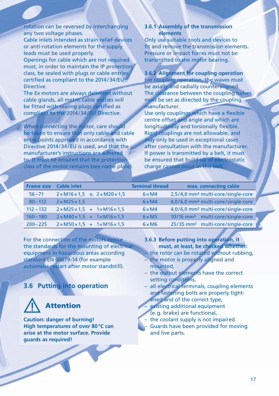
Frame size Cable inlet Terminal thread max. connecting cable
56 – 71 2 × M16 × 1,5 o. 2 × M20 × 1,5 6 × M4 2,5 / 4,0 mm² multi-core / single-core
80 – 112 2 × M25 × 1,5 6 × M4 4,0 / 6,0 mm² multi-core / single-core
112 – 132 2 × M25 × 1,5 + 1 × M16 × 1,5 6 × M4 4,0 / 6,0 mm² multi-core / single-core
160 – 180 2 × M40 × 1,5 + 1 × M16 × 1,5 6 × M5 10 / 16 mm² multi-core / single-core
200 – 225 2 × M50 × 1,5 + 1 × M16 × 1,5 6 × M6 25 / 35 mm² multi-core / single-core
For the connection of the motors notice the standards for the mounting of electrical equipment in hazardous areas according standard EN 60079-14 (for example automatic restart after motor standstill).
3.6 Putting into operation
Attention
Caution: danger of burning!High temperatures of over 80 °C can arise at the motor surface. Provide guards as required!
3.6.1 Assembly of the transmission elements
Only use suitable tools and devices to fit and remove the transmission elements. Pressure or impact forces must not be transmitted to the motor bearing.
3.6.2 Alignment for coupling operationFor coupling operation, the waves must be axially and radially counteraligned. The clearance between the coupling halves must be set as directed by the coupling manufacturer.Use only couplings which have a flexible centre offset and angle and which are longitudinally and torsionally flexible. Rigid couplings are not allowable, and may only be used in exceptional cases after consultation with the manufacturer.If power is transmitted by a belt, it must be ensured that build-up of electrostatic charge cannot occur in this belt.
3.6.3 Before putting into operation, it must, at least, be checked whether:
– the rotor can be rotated without rubbing,– the motor is properly aligned and
mounted,– the output elements have the correct
setting conditions,– all electrical terminals, coupling elements
and fastening bolts are properly tight-ened and of the correct type,
– existing additional equipment (e. g. brake) are functional,
– the coolant supply is not impaired– Guards have been provided for moving
and live parts.

18
3.6.4 Maximum surface temperatures according to VDMA / ZVEI 24263:2011-02
Temperature class T3
Number of pole pairs
max. shaft temperature
max. flange temperature
2-pole 60 °C 60 °C
4-pole 75 °C 75 °C
Frame work conditions:– maximal permissible temperatures on the
shaft end and motor flange– no frequency inverter operating– self ventilated– frame size 63 until 200 – motor according DIN EN 50347– ambient temperature − 20 °C up to + 40 °C
4. Maintenance
Attention
Before conducting work of any nature on the motor, the motor must be disconnected from the power supply and prevented from restarting!
In addition to the main circuits, attention must be paid to the presence of any additional or auxiliary circuits!
4.1 Inspection
Depending on the degree of soiling, the motors must be cleaned routinely over their full surface, e. g. using dry compressed air.
The first inspection must normally be conducted after approx. 500 operating hours, at the latest after 1 year. Follow-up inspections should, depending on the conditions of use, be conducted at appropri-ate intervals, e.g. re-greasing and grease change intervals, but at least once a year.
During inspections it must be checked that– the technical data as specified on the
rating plate are met,– no leakages (oils, grease, water) exist,– the running noise of the bearings and
the smoothness of the motor have not deteriorated,
– all fastening bolts for electrical and mechanical connections are secure,
– the alignment of the motor lies within the allowable tolerances during coupling operation.
4.2 Bearings
4.2.1 Bearings greased for life timeThe bearings of the motors greased for life time are maintenance free under normal operating conditions for between 10,000 and 20,000 operating hours, but for no longer than 3 years .
In the case of motors which have bearings sealed by two caps (2Z bearings) and which operate speeds of up to 3,600 RPM, the bearings should be replaced after 20,000 operating hours, at the latest after 3 years.
In the case of motors which are sealed by a single cap (Z bearings) or a single bearing end cap, the grease must be changed– after 20,000 operating hours of operation at speeds up to 1800 RPM,– after 10,000 operating hours of operation at speeds up to 3600 RPM,but, at the latest, after 3 years; the bearings must also be replaced if necessary.
4.2.2 Bearings with re-greasing deviceIn the case of motors with a re-greasing device, the re-greasing interval, the exact quantity of grease and grease grade are specified on an additional plate on the motor. If the number of operating hours specified on the lubrication plate has not elapsed within 3 years, the bearings should nevertheless be re-greased. Re-grease the bearings only with the rotor rotating, so that the new grease is distributed in the bearings!

19
Guide values for standard greasing
Frame size
Quantity of grease per bearing
Frame size
Quantity of grease per bearing
90 3 g 160 10 g
100 4 g 180 14 g
112 6 g 200 18 g
132 8 g 225 18 g
Attention
Mixing of different grease types should be avoided!
4.3 Repair work
Spare parts lists and normal graphical representations contain no detailed information on the type and dimensions of the components. Therefore, determine the assignment of the respective components during disassembly and mark the compo-nents for assembly.
4.3.1 Replacement of bearingsDisassemble the motor to the extent required. Pull off roller bearings using a suitable device and clean the bearings!Heat new roller bearing evenly to a temperature of approx. 80 °C and fit it. Fill approx. 50 % of the space in the bearing as well as the grease spaces in the endshield or bearing cover with approved types of grease.
Sealing elements (e. g. rotary shaft seals) must be checked for correct function and damage prior to assembly and replaced if they are no longer sufficiently effective.
5. Additional notes on brake motors
Attention
After mounting the motors, check that the brake is in proper working order!
5.1 General information
The mounted brake is a safety brake and provides braking by spring pressure when the power is off. The brake is vented via an electromagnet.
5.2 Circuit and connection
The brake system is connected at a separate terminal box of the mounted brake or in the terminal box of the motor as shown in the respective enclosed circuit diagram. The supply voltage to be applied is specified on an additional plate mounted to the brake.
Warning:The motor must not start against the closed brake!Configure the circuit in such a manner that the brake is vented before the motor is switched on.Brake size and motor sized must be matched. This matching may not be changed with- out the motor manufacturer’s express approval. The type test approval and operating manual of brake are enclosed.
5.3 Maintenance
The mounted brakes are virtually mainte-nance free, apart from the need to replace worn friction discs and check the electrical safety chain (micro-switch and thermostatic switch). If the maximum allowable air gap is exceeded, the response time of the brake will increase markedly or, in unfavourable

20
voltage ratios, the brake will stop venting. The maintenance cycle for checking the brake must be integrated into the mainte-nance cycle for checking the motor.
5.4 Backstops and roller freewheels (optional)
When installing backstops and roller free-wheels, pay attention to the correct direction of rotation. The correct direction of rotation is indicated by an arrow on the motor.
5.5 Anti-condensation heaters
The motors can be supplied with a self- limiting space heater. When connecting, make sure that the space heater is only working when the motor is not in opera-tion, other-wise the temperature class may be exceeded.
6. Operating modes
The motors may, unless otherwise certified, only be used for continuous duty (S1) and normal, non-frequently recurring starts with no significant temperature rise at starting. If motors with ignition protection class “eb” are used for heavy starting > 1.7 × tE , they must be protected by a start monitoring device as specified EC / EU-Type-Examination Certificate.
6.1.1 Motor protection with current-dependet relay
The motors must, by means of bimetallic motor protection switches, be provided with all-pole protection against unacceptable heating due to overloading. In addition, precautions must be taken to prevent operation of a three-phase a. c. motor in the event of phase failure. These guards must be designed in such a way that they monitor the nominal current and disconnect the stalled motor within time tE.
To this end, tripping characteristics which represent the tripping time as a function of the starting current ratio IA / IN must be available for the associated triggers or relays. The characteristics should represent the tripping times starting from the cold state at an ambient temperature of 20 °C in dependence on a multiple of at least 3 – 8 × nominal current. The guards must achieve the specified tripping times within a tolerance of ± 20 %.When selecting the current-dependent relay care should be taken to ensure that this has a phase failure recognition system and an imbalance recognition system. The use of a relay approved in accordance with Directive 2014 / 34 / EU is recommended.In the case of pole-changing motors, an overload safety device must be provided for each speed. The circuit-breakers must be locked in such a way that the motor cannot be switched to a different speed when a switch trips.
6.1.2 Motor protection with PTC thermistorsEngines in type of protection increased safety “eb”, which are certified for opera-tion with frequency converter are only allowed to operate within the specified limits according to the data sheet or name plate. This means in particular the monitor-ing of the continuous current in dependence of the frequency.Allowed to used are only frequency converters that meet the requirements specified in the type examination certificate.The evaluation of the built-in PTC thermis-tors shall be carried out by a tripping unit with Ex designation II (2) G in accordance with the requirements of Directive 2014 / 34 / EU. The specified speed or frequency must never be exceeded. The max. permissible pulse voltage must not exceed the specification in the data sheet.It may be necessary to use filters or throttles between the converter and motor. Further-more, it must be ensured that the applied motor voltage complies with the information

21
given on the name plate (note the voltage drop of the connecting cable and if necessary filters or chokes). If in case of voltage drops, the terminal voltage at the motor is lower than specified on the rating plate or in the data sheet, then the cut-off frequency should be set to a smaller value in accordance with a linear voltage/frequency assignment. The speed control range is thus smaller.
6.2 Motor connection
The supply lead must be introduced into the cable entry in such a manner that twisting is prevented and strain relief is assured. Motors for explosion hazard areas must be provided with suitable terminals and spring lock washers. In addition, the minimum air gap must be observed when connecting the cable.Connect the grounded conductor to the PE terminal inside the terminal box or, if the grounding conductors are laid separately, to the outer earth terminal in a U shape or with a terminal end so that good conductivity is provided (refer to figures on the right). The screw connections for electrical connections are tightened with a defined torque, according to the table below.
Thread Tightening torque
M4 1,2 Nm
M5 2,0 Nm
M6 3,0 Nm
M8 6,0 Nm
M10 10,0 Nm
Terminal diagram
or
Terminal diagram
or
or
6.3 Repairs
To maintain explosion protection, repairs that affect the type of protection may only be performed by the manufac turer himself or by an officially accredited expert.If necessary, consult with the manufacturer.
6.3.1 Paint WorkIn order to avoid to build up electrostatic charge in normal use, maintenance and cleaning work the applied paint including primer must not exceed the 0,20 mm according standard 60079-0 for the device in group llC.This ensures that any possible electrostatic charges are discharged through the paint layer on the housing, which has a potential equalization.Prerequisite is the proper connection of the equipotential bonding connection to earth.For various reasons, a layer thickness of more than 0,20 mm is required, an antistatic coating must be used, which reduces the surface resistance.

22
7. Single-phase motor
The single-phase motors are equipped with a running capacitor. Due to the low starting torque, only no-load starting or reduced- load starting is possible. The capacitor cable connected to the motor is unsuitable as a carrying or transportation aid.An EC / EU-Type-Examination Certificate to Directive 2014 / 34 / EU is available for the mounted running capacitor.The explosion-protected motor capacitor is a capacitor built into an aluminium enclosure with type of protection Powder Filling “qb”.
Electrical data:Capacitance tolerance: ± 5 %Protection class: IP 64Coolant temperature: −20 °C to + 50 °CExplosion protection: II2G Ex qb IIC T6 GbOnly original running capacitors should be used as replacements.
8. Spare parts
Please always state, in addition to the exact parts designation, the motor type and motor number (data are specified on the rating plate) when you order spare parts.With the exception of standardized readily available and equivalent parts, e. g. ball bearings, only original parts may be used. This applies in particular to seals and terminals.

23

24
Ersatzteile
Teile-Nr. Part No.
Bezeichnung Description
1.0 Gehäuse (IMB3) Casing (IMB3)
1.1 Gehäuse ohne Füße (IMB5 / IMB14) Casing without feet (IMB5 / IMB14)
1.2 Motorfüße Motor feet
2.0 Statorpaket mit Wicklung Stator cove with winding
3.1 Rotor mit Welle Rotor with shaft
4.0. Lagerschild AS (IMB3) Endshield drive end (IMB3)
4.1 Flanschlagerschild (IMB5) Flange endshield (IMB5)
4.2 Flanschlagerschild (IMB14) Flange endshield (IMB14)
5.1 Lagerschild BS Endshield non drive end
6.0 Lagerdeckel ASi Bearing cover drive end internal
6.1 Lagerdeckel ASa Bearing cover drive end external
6.2 Lagerdeckel BSi Bearing cover non drive end internal
6.3 Lagerdeckel BSa Bearing cover non drive end external
6.4 Schleuderscheibe Grease slinger drive end
7.0 Lüfter Fan
8.2 Lüfterhaube Fan cover
9.2 Klemmenkastenrahmen Terminal box frame
9.3 Klemmenkastenrahmendichtung Gasket of terminal panel box frame
10.0 Klemmbrett, komplett Terminal, complete
11.2 Klemmenkastendeckel Terminal box cover
11.3 Klemmenkastendeckeldichtung Gasket of terminal panel box cover
12.0 Wälzlager AS Roller bearings drive end
12.1 Wälzlager BS Roller bearings non drive end
13.0 Wellendichtring Shaft seal
13.1 Wellendichtring Shaft seal
14.0 Sicherungsring (Wälzlager) Securing ring (roller bearings)
14.1 Sicherungsring (Wälzlager) Securing ring (roller bearings)
14.2 Sicherungsring (Lüfter) Securing ring (fan)
15.0 Wellenbandfeder Spring plate
16.0 Ringschraube Eyebold
17.1 Kabel-Verschraubung Motor connect plug
19.0Kondensator (nur Einphasenmotoren)
Capacitor (only single-phase motors)
Bestellbeispiel Baugröße: 160 L Motor.-Nr.: 3574507Bauteil: 3.1 Rotor mit Welle
Specimen order Frame size: 160 LMotor serial number: 3574507Component: 3.1 Rotor with shaft

25

26

27
Konformitätsbewertungsstelle für EG / EU-Baumusterprüfbescheinigungen
Physikalisch-Technische BundesanstaltBundesallee 100 36116 Braunschweig / Deutschland Kenn-Nummer: 0102
Konformitätsbewertungsstelle für Qualitätssicherung Produkt gemäß Anhang VII für elektrische Betriebsmittel nach Richtlinie 2014 / 34 / EU
TÜV Süd Product Service GmbH Ridlerstraße 65 80339 München / Deutschland Kenn-Nummer: 0123
Auflistung der zugehörigen EG-Baumusterprüfbescheinigungen:Listing of related EC type-examination certificates.
EG-BaumusterprüfbescheinigungEC declaration of conformity
Typetype
Datenblattdata sheet
PTB 03 ATEX 3004 EeEA 56 L / 2 a 1 – 2
+ 1. Ergänzung + 2. Ergänzung + 3. Ergänzung + 4. Ergänzung
PTB 02 ATEX 3114 EeDA 56 L / … 1 – 9
+ 1. Ergänzung + 2. Ergänzung + 3. Ergänzung + 4. Ergänzung
PTB 02 ATEX 3128 EeDA 63 S / … und EeDA 63 L / … 1 – 12
+ 1. Ergänzung + 2. Ergänzung + 3. Ergänzung + 4. Ergänzung
PTB 02 ATEX 3169 EeDA 71 S / … und EeDA 71 L / … 1 – 17
+ 1. Ergänzung + 2. Ergänzung + 3. Ergänzung + 4. Ergänzung
PTB 02 ATEX 3115 EeDA 80 S / … und EeDA 80 L / … 1 – 19
+ 1. Ergänzung + 2. Ergänzung + 3. Ergänzung + 4. Ergänzung
PTB 06 ATEX 3026 EeDA 80 S / … 1
+ 1. Ergänzung + 2. Ergänzung + 3. Ergänzung
PTB 02 ATEX 3173 EeDA / G 90 S / … und EeDA / G 90 / L… 1 – 19
+ 1. Ergänzung + 2. Ergänzung + 3. Ergänzung + 4. Ergänzung
PTB 03 ATEX 3007 EeDA / G 100 L / … 1 – 12
+ 1. Ergänzung + 2. Ergänzung + 3. Ergänzung + 4. Ergänzung
PTB 06 ATEX 3025 X EeDA / G 100 L / … 1
+ 1. Ergänzung + 2. Ergänzung + 3. Ergänzung
PTB 03 ATEX 3009 EeDA / G 112 M / … 1 – 8
+ 1. Ergänzung + 2. Ergänzung + 3. Ergänzung + 4. Ergänzung
PTB 03 ATEX 3022 EeDG 132 S / … und EeDG 132 M / … 1 – 22
+ 1. Ergänzung + 2. Ergänzung + 3. Ergänzung + 4. Ergänzung
PTB 03 ATEX 3039 EeDG 160 M / … und EeDG 160 L / … 1 – 16
+ 1. Ergänzung + 2. Ergänzung + 3. Ergänzung + 4. Ergänzung
PTB 03 ATEX 3062 EeDG 180 M / … und EeDG 180 L / … 1 – 5
+ 1. Ergänzung + 2. Ergänzung + 3. Ergänzung + 4. Ergänzung
PTB 03 ATEX 3098 EeDG 200 LK / … und EeDG 200 L / … 1 – 3
+ 1. Ergänzung + 2. Ergänzung + 3. Ergänzung + 4. Ergänzung
PTB 03 ATEX 3112 EeDG 225 S / … und EeDG 225 M / … 1 – 2
+ 1. Ergänzung + 2. Ergänzung + 3. Ergänzung + 4. Ergänzung

© c
re ar
t.de