bettis q-series actuator installation operation & maintenance manual
TRANSCRIPT

www.Bett is.com
APPROVED
Bettis Q-Series Valve Actuator
Installation Operation & Maintenance ManualDOC.IOM.BQ.E Rev: 0April 2014

Page 2
Installation Operation & Maintenance ManualDOC.IOM.BQ.E Rev: 0
April 2014

Page 3
Installation Operation & Maintenance ManualDOC.IOM.BQ.E Rev: 0April 2014
ContentsA Before you start ............................... 4
A1 Orientation(seefig.A1) ............................ 4A2 Installation, operation and maintenance
reference documents ................................ 4A3 Operating medium .................................... 4A4 Product integrity ........................................ 4A5 Hazardous areas ...................................... 5A6 Warning ; Moving parts ............................. 5A7 Prevent moisture entering the actuator .... 5A8 Warehouse storage .................................. 5A9 On site storage .......................................... 5A10 Lifting instructions ..................................... 5
1 Introduction ....................................... 61.1 Orientation(seefig.1.1) ........................... 6
2 Installation ......................................... 72.1 Before you start ......................................... 72.2 Failure modes ........................................... 72.3 Operating principle .................................... 82.4 Actuator assembly codes ..................... 122.5 Valve Installation ..................................... 142.6 Recommended tubing sizes ................... 152.7 Air consumption per stroke at
atmospheric pressure ............................. 15
3 Mechanical stroke adjustment ...... 163.1 Adjusting the “Open” position ................. 163.2 Adjusting the “Closed” position ............... 163.3 Adjusting the end position with no electrical
wiring connected. .................................... 17
4 Removing and mounting of the Bettis Q-Series Modules ................ 184.1 Removing the Bettis Q-Series modules . 184.2 Mechanical alignment and mounting
of the control module .............................. 184.3 Tightning moments ................................. 184.4 Connecting air supply ............................. 18
5 Speed control option ..................... 195.1 MountingSpeedControlthrottle(s): ....... 192 AdjustingSpeedControlthrottle(s): ....... 19
6 Manual Control option ................... 206.1 Mounting Manual Control ....................... 206.2 Manual Control operation ....................... 20
7 Trouble shooting Bettis Q-Series .. 217.1 Mechanical problems .............................. 217.2 Pneumatic problems ............................... 217.3 Electrical problems .................................. 22
8 Maintenance .................................... 238.1 General .................................................... 238.2 Single acting / Spring Return actuators . 238.3 Bettis Q-Series recommended spare
parts ......................................................... 238.4 Position tracking device kits ................... 238.5 Conversion kits ....................................... 238.6 High Temp and Low Temp Conversion
kits ........................................................... 23
9 Disassembly .................................... 249.1 Before starting ........................................ 249.2 Removing end caps all types QD and
QS 40 to QS 350 .................................... 259.3 Removing end caps type QS 600
to 1600 .................................................... 269.4 Removing limit stop bolts, pistons and
pinion assembly. ..................................... 27
10 Reassembly ..................................... 2910.1 Reassembly guide band and pinion
assembly ................................................. 2910.2 Reassemble the pistons ......................... 3110.3 Reassembly end caps, all types QD and
QS 40 to QS 350 .................................... 3210.4 Reassembly end caps single acting
actuators QS 600 to QS 1600 ................ 3310.5 Mounting and setting of limit stops ......... 3410.6 Final assembly and airtightness test ...... 35
11 Bettis Q-Series Parts ...................... 3611.1 Exploded view Bettis Q-Series
(baseactuator) ........................................ 3611.2 Bill Of Material ......................................... 3711.3 Exploded view Bettis Q-Series
(ControlModule) ..................................... 38

Page 4
Installation Operation & Maintenance ManualDOC.IOM.BQ.E Rev: 0
April 2014
A Before you start A2 Installation, operation and
maintenance reference documentsBefore mounting, installing, commissioning or (dis)assemblingtheactuatorconsultthefollowingdocuments:- All chapters of this manual and- Installation Guide of the supplied Control Module.- For installation in hazardous area’s:
The applicable section of the Installation Guide, as shipped with the Control Module.
- For Control Modules with bus communication there may be an additional Reference Manual with more detailed information.
(availablefromwww.Bettis.com).
A3 Operating medium• Airorinertgasses: - Filtered to 50 micron. - Check the Installation Guide as shipped with the
module for the applicable air quality.• Maximumpressure,8barg/120psig• Dewpoint10Kbelowoperatingtemperature.• Forsubzeroapplicationstakeappropriate
measures.
A4 Product integrity• Assemblyordisassemblyisonlyallowedforreplacingsealsandguidebands(softparts).
Fig A1 Orientation
• BettisQ-Seriesactuatorsmustbeisolatedbothpneumaticallyandelectricallybefore(dis)assembly.
• Itisnotpermittedtoconnectapressurevesselwith unreduced media to the Bettis Q-Series pneumatic actuator.
• BettisQ-Seriesactuatorsmustnotbeconnectedto an air supply greater than 8 bar g or 120 psig
• Thismanualdoesnotprovideinstructionsforinstallations in hazardous areas.
• Installation,adjustment,puttingintoservice,use,assembly, disassembly and maintenance of the pneumaticactuatormustbedonebyqualifiedpersonnel.
A1 Orientation(seefig.A1)The Bettis Q-Series actuator is an integrated concept for the automation of quarter turn valves, dampers or other quarter turn applications. It can consists of three basic parts:1. Pneumatic actuator,2. NAMUR Plate or3. Control Module
1
2
3

Page 5
Installation Operation & Maintenance ManualDOC.IOM.BQ.E Rev: 0April 2014
A5 Hazardous areasImproper installation in a hazardous area can cause an explosion.
• Assembly,disassemblyandmaintenancemustbedone in safe area’s without a potential explosion hazard.
• Forinformationaboutinstallationinahazardousarea, refer to the appropriate sections of the Installation Guide, as shipped with the control module.
A6 Warning ; Moving partsApplying pressure to the actuator or Applying a control signal to the Control Module, may cause the actuator/valve assembly to operate.
A7 Prevent moisture entering the actuator
Condensation or moisture that enters the actuator or the Control Module can damage these components and can result in failures. Therefore:• Trynottomounttheactuatorwiththeconduit
openings or the air entries, pointing upward.• Ensureintegrityofgasketsando-rings.• Installdriploopsinconduitorcable.• Sealallconduitopeningswhetherusedornot.
OKFig A2 Install drip loops
A8 Warehouse storage• BettisQ-SeriesActuatorsandControlModules
should be stored in a clean, dry warehouse, free from excessive vibration and rapid temperature changes.
• Actuatorsshouldnotbestoredonanyfloorsurface.
A9 On site storage• BettisQ-SeriesActuatorsandControlModules
should be stored in a clean, dry warehouse, free from excessive vibration and rapid temperature changes.
• Ensureallactuatorcoversareinplaceandsecurely fastened.
• Replaceplasticconduitplugswithappropriatepipe plugs.
Failure to follow proper storage guidelines will voidwarranty.
A10 Lifting instructions• Useliftingequipementasrequiredbynationalor
local legislation.Table A1 Weight of Actuators with
control modulesACTUATOR TYPE
Double acting
Spring Return
Double acting
Spring Return
in kg. in Ib
Q40 3.9 4.5 8.6 9.9Q65 4.5 5.7 9.9 12.6Q100 5.2 6.7 11.5 14.8Q150 6.9 9 15.2 19.8Q200 7.9 11.2 17.4 24.7Q350 12.5 19 27.6 41.9Q600 21.5 29.7 47.4 65.5Q950 28.5 40.7 62.8 89.7Q1600 44.8 67.9 98.8 149.7
• Itisstronglyrecommendedtouseliftingstrapstolift the actuator/valve assembly.
• Ifanactuator/valveassemblyshouldbelifted,itis strongly recommended to connect the lifting straps in such way that the actuator and valve is supported.

Page 6
Installation Operation & Maintenance ManualDOC.IOM.BQ.E Rev: 0
April 2014
1 Introduction1.1 Orientation(seefig.1.1)
Fig 1.1 Introduction
5. Entries for optional manual control6. Exhausts7. Supply air entry8. Entries for optional speed control
1. Pneumatic actuator2. Visual Position Indication3. Stroke adjustment bolts4. Control Module
The Bettis Q-Series actuator is an integrated concept for the automation of quarter turn valves, dampers or other quarter turn applications.
1
2
3
4
5 6
7
8
Factory setting: Rotation 90°±0.5°
Insert according ISO 5211 or DIN 3337
Optional insert shapes
Page 7
Installation Operation & Maintenance ManualDOC.IOM.BQ.E Rev: 0April 2014
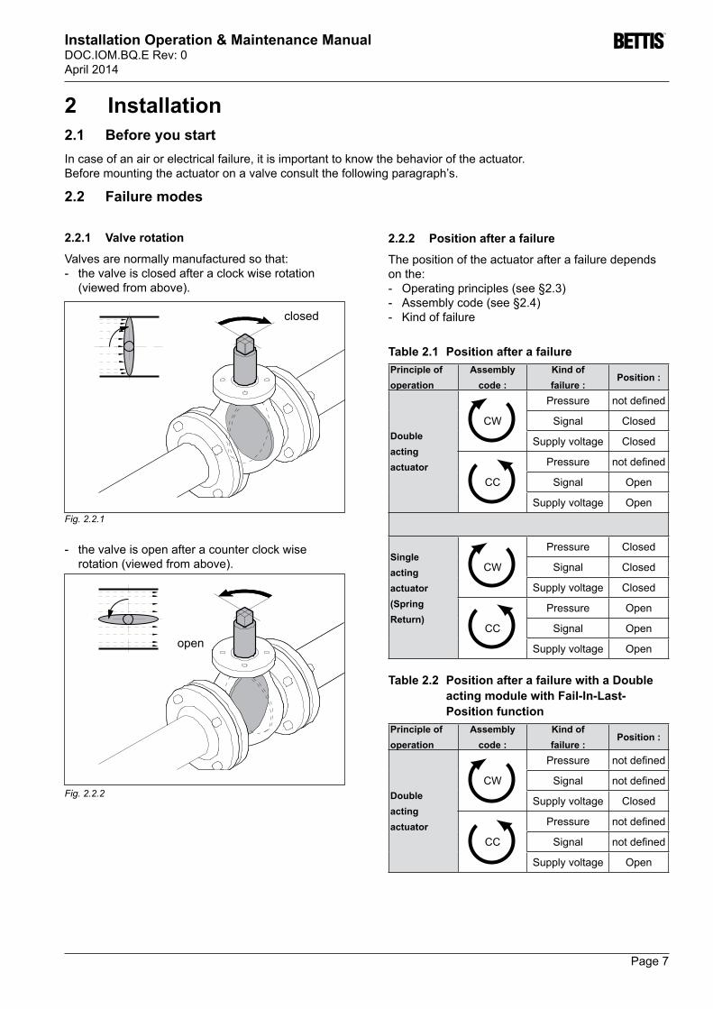
2 Installation2.1 Before you startIn case of an air or electrical failure, it is important to know the behavior of the actuator. Before mounting the actuator on a valve consult the following paragraph’s.
2.2 Failure modes
Fig. 2.2.2
Fig. 2.2.1
closed
open
- the valve is open after a counter clock wise rotation(viewedfromabove).
2.2.2 Position after a failure
The position of the actuator after a failure depends on the:- Operatingprinciples(see§2.3)- Assemblycode(see§2.4)- Kindoffailure
Table 2.1 Position after a failurePrinciple of operation
Assembly code :
Kind of failure :
Position :
Double acting actuator
CW
Pressure notdefined
Signal Closed
Supply voltage Closed
CC
Pressure notdefined
Signal Open
Supply voltage Open
Single acting actuator (Spring Return)
CW
Pressure Closed
Signal Closed
Supply voltage Closed
CC
Pressure Open
Signal Open
Supply voltage Open
Table 2.2 Position after a failure with a Double acting module with Fail-In-Last-Position function
Principle of operation
Assembly code :
Kind of failure :
Position :
Double acting actuator
CW
Pressure notdefined
Signal notdefined
Supply voltage Closed
CC
Pressure notdefined
Signal notdefined
Supply voltage Open
2.2.1 Valve rotation
Valves are normally manufactured so that: - the valve is closed after a clock wise rotation
(viewedfromabove).

Page 8
Installation Operation & Maintenance ManualDOC.IOM.BQ.E Rev: 0
April 2014
B-portA-port
PsRb
5/2 Spool valve
Ra
Option: LMC
Option: Throttle 1
Option:Throttle 2
Pilot valve 1
2.3 Operating principleSee paragraph 2.4 for more information about actuator assembly codes
* Electric control signals can be connected in the Control Module (QC; see documentation supplied withtheControlModule).TheControlModuleisequipped with a pilot valve which controls a 5/2 spool valve.
* Connectairsupplytoairinlet(Ps).
Outward stroke
1 Send control signal “Open” to the Control Module.2 Pilot valve 1 will be activated and the 5/2 spool
valve will pressurize the central air chamber.3 The piston will move outwards to the “Open”
position.4 The Control Module indicates the “Open” position
and activates feedback signal “Open”.
Inward stroke
1 Send control signal “Close” to the Control Module.2 Pilot valve 1 will be deactivated and the 5/2 spool
valve will pressurize the end cap air chambers.3 The piston will move inwards to the “Closed”
position.4 The Control Module indicates the “Closed”
position and activates feedback signal “Closed”.
Optional controls:
LMC Local Manual ControlSC Speed Control throttles
IMPORTAnT:
In case of an electric control signal failure, the actuator will move to its “Closed” position.
2.3.1 Double acting actuators
IMPORTAnT
The operating principle, as explained here, is applicable for actuators with assembly code CW (directacting).- The outward stroke will move the valve to the
“Open” position. - The inward stroke will move the valve to the
“Closed” position.
For assembly codes CC the operating principle is reversed(reverseacting):
B-portA-port
PsRb
Pilot valve 1
5/2 Spool valve
Ra
Option: LMC
Option: Throttle 1
Option:Throttle 2
Fig. 2.3.1
Fig. 2.3.2

Page 9
Installation Operation & Maintenance ManualDOC.IOM.BQ.E Rev: 0April 2014
2.3.2 Double acting actuators with Fail In Last Position function
IMPORTAnT
The operating principle, as explained here, is applicable for actuators with assembly code CW (directacting).- The outward stroke will move the valve to the
“Open” position. - The inward stroke will move the valve to the
“Closed” position.
For assembly codes CC the operating principle is reversed(reverseacting):
See paragraph 2.4 for more information about actuator assembly codes
* Electric control signals can be connected in the Control Module (QC; see documentation supplied withtheControlModule).TheControlModuleisequipped with a pilot valve which controls a 5/2 spool valve.
* Connectairsupplytoairinlet(Ps).
Outward stroke
1 Send control signal “Open” to the Control Module to activate Pilot valve 1 and de-activate Pilot valve 2.
2 The 5/2 spool valve will pressurize the central air chamber.
3 The piston will move outwards to the “Open” position.
4 The Control Module indicates the “Open” position and activates feedback signal “Open”.
Inward stroke
1 Send control signal “Close” to the Control Module to activate Pilot valve 2 and de-activate Pilot valve 1.
2 The 5/2 spool valve will pressurize the end cap air chambers.
3 The piston will move inwards to the “Closed” position.
4 The Control Module indicates the “Closed” position and activates feedback signal “Closed”.
Optional controls:
LMC Local Manual ControlSC Speed Control throttles
B-portA-port
Ps
Pilot valve 1
5/2 Spool valve
Pilot valve 2
Option: LMC 1Option: LMC 2
Option:Throttle 1
Option:Throttle 2
Rb
Ra
B-portA-port
Ps
Pilot valve 1
5/2 Spool valve
Pilot valve 2
Option: LMC 1 Option: LMC 2
Option:Throttle 1
Option:Throttle 2
Rb
Ra
Fig. 2.3.3
Fig. 2.3.4

Page 10
Installation Operation & Maintenance ManualDOC.IOM.BQ.E Rev: 0
April 2014
A-port B-port
Ps
Pilot valve 1
3/2 Spool valve
Ra
Option: LMC
Option: Throttle 1
A-port B-port
Ps
Pilot valve 1
3/2 Spool valve
Ra
Option: LMC
Option: Throttle 1
See paragraph 2.4 for more information about actuator assembly codes
* Electric control signals can be connected in the Control Module (QC; see documentation suppliedwiththeControlModule).TheControlModule is equipped with a pilot valve controls a 3/2 spool valve.
* Connectairsupplytoairinlet(Ps).
Outward stroke
1 Send control signal “Open” to the Control Module.2 Pilot valve 1 will be activated and the 3/2 spool
valve will pressurize the central air chamber.3 The piston will move outwards to the “Open”
position4 The Control Module indicates the “Open” position
and activates feedback signal “Open”.
Inward stroke
1 Send control signal “Close” to the Control Module.2 Pilot valve 1 will be deactivated and the 3/2 spool
valve will vent the central air chamber3 The springs will move the pistons inwards to the
“Closed” position4 The Control Module indicates the “Closed”
position and activates feedback signal “Closed”.
Optional controls:
LMC Local Manual ControlSC Speed Control throttles
Fig. 2.3.5
Fig. 2.3.6
2.3.2 Singleacting(springreturn)actuators
IMPORTAnT
The operating principle, as explained here, is applicable for actuators with assembly code CW (directacting).- The outward stroke will move the valve to the
“Open” position. - The inward stroke will move the valve to the
“Closed” position.
For assembly code CC the operating principle is reversed(reverseacting):
Page 11
Installation Operation & Maintenance ManualDOC.IOM.BQ.E Rev: 0April 2014
3
1
2
4
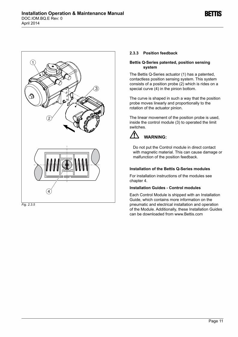
2.3.3 Position feedback
Bettis Q-Series patented, position sensing system
TheBettisQ-Seriesactuator(1)hasapatented,contactless position sensing system. This system consistsofapositionprobe(2)whichisridesonaspecialcurve(4)inthepinionbottom.
The curve is shaped in such a way that the position probe moves linearly and proportionally to the rotation of the actuator pinion.
The linear movement of the position probe is used, insidethecontrolmodule(3)tooperatedthelimitswitches.
WARnInG:
Do not put the Control module in direct contact with magnetic material. This can cause damage or malfunction of the position feedback.
Installation of the Bettis Q-Series modules
For installation instructions of the modules see chapter 4.
Installation Guides - Control modules
Each Control Module is shipped with an Installation Guide, which contains more information on the pneumatic and electrical installation and operation of the Module. Additionally, these Installation Guides can be downloaded from www.Bettis.com
Fig. 2.3.5

Page 12
Installation Operation & Maintenance ManualDOC.IOM.BQ.E Rev: 0
April 2014
2.4 Actuator assembly codes
2.4.1 Double acting assembly codes
2
12
2
12
12
2
12
2
B
A
A
B
B
A
A
B
2
12
2
12
12
2
12
2
B
A
A
B
B
A
A
B
2
12
2
12
12
2
12
2
B
A
A
B
B
A
A
B
2
12
2
12
12
2
12
2
B
A
A
B
B
A
A
B
CC
I
CW
C
CC
C
Standard assembly code: (= Clock WiseRotation)Visual indicator mounted:(= for In line position indication
Pinion
Position indicator
Pistons
A = Pilot valve operatedinControlModule - Centralairchamber(1)pressurizedB = Pilot valve not operatedinControlModule - Endcapairchambers(2)pressurized
All views are from above. Pistons are shown in inner position
Optional assembly code: (= Counter Clock WiseRotation)Visual indicator mounted:(= for In line position indication
Optional assembly code: (= Clock WiseRotation)Visual indicator mounted:(= for Crosslinepositionindication)
Optional assembly code: (= Counter Clock WiseRotation)Visual indicator mounted:(= for Crosslinepositionindication)
CW
I

Page 13
Installation Operation & Maintenance ManualDOC.IOM.BQ.E Rev: 0April 2014
2.4.2 Singleacting(SpringReturn)assemblycodes
B
A
2
1 2
B
A
2
1 2
B
A
2
1 2
B
A
2
1 2
B
A
2
1 2
B
A
2
1 2
B
A
2
1 2
B
A
2
1 2
B
A
2
1 2
B
A
2
1 2
B
A
2
1 2
B
A
2
1 2
B
A
2
1 2
B
A
2
1 2
B
A
2
1 2
B
A
2
1 2
Standard assembly code: (= Clock Wise Rotation / SpringtoClose)Visual indicator mounted:(= for In line position indication
Pinion
Optional assembly code: (= Clock Wise Rotation / Spring to Close)Visual indicator mounted:(= for Cross line position indication
Position indicator
Pistons
Optional assembly code:(= Counter Clock Wise Rotation / SpringtoOpen)Visual indicator mounted:(= for Cross line position indication
A = Pilot valve operatedinControlModule - Centralairchamber(1)pressurizedB = Pilot valve not operated in Control Module - Springstroke(2)
All views are from above. Pistons are shown in inner position
Optional assembly code: (= Counter Clock Wise Rotation / SpringtoOpen)Visual indicator mounted:(= for In line position indication
CC
C
CW
C
CC
I
CW
I

Page 14
Installation Operation & Maintenance ManualDOC.IOM.BQ.E Rev: 0
April 2014
1 2
ISO 5211 DIN 3337
90°45°
Fig. 2.5.4
Fig. 2.5.5
2.5 Valve InstallationWARnInG! Actuator must be isolated both pneumatically andelectricallybefore(dis)assembly.Before
Fig. 2.5.1
Fig. 2.5.2
Fig. 2.5.3
CAUTIOn!Be sure that the insert is mounted at 90° or 45°.
mountingor(dis)assemblingtheactuatorconsulttherelevant sections of this manual.
Remove handle nut, handle, lock washer, etc. from valve if required.
It is possible to mount the insert turned 22.5°. This way the valve will not open or close the right way.
CAUTIOn! - Before mounting the actuator on the valve
be sure that both the actuator and the valve have the same position.
- When mounting do not hit with hammer on pinion top.
IMPORTAnT!- When mounting the actuator across the
pipeline, the NAMUR slot at the pinion topisturned90°anddoesnotreflecttheposition of the valve blade.
- WhenmountingNAMUR(VDI/VDE3845)switch boxes or positioners take care that these devices can be and will be set to reflecttheactuallimitpositions.
OK
OK

Page 15
Installation Operation & Maintenance ManualDOC.IOM.BQ.E Rev: 0April 2014
2.6 Recommended tubing sizes
Actuator Model no. Runs up to 1.2 mtr / 4 ft. Runs over 1.2 mtr. / 4 ft.
Q-40, 65 6 mm / 1/4” 6 mm / 1/4”
Q-100, 150, 200, 350 6 mm / 1/4” 8 mm ~ 5/16”
600, 950, Q1600 8 mm / 1/4” 10 mm ~ 3/8”
2.7 Air consumption per stroke at atmospheric pressure Air chamber -at1atm(litres)
Model
Q40 Q65 Q100 Q150 Q200 Q350 Q600 Q950 Q1600
Central air chamber 0.16 0.33 0.35 0.84 0.8 1.8 2.9 4.7 7.3End cap air chambers 0.22 0.36 0.49 0.78 1 1.9 3.1 4.9 8.0
-at1atm(cu./in.)Central air chamber 10 20 21 51 49 110 177 287 445End cap air chambers 13 22 30 48 61 116 189 299 488

Page 16
Installation Operation & Maintenance ManualDOC.IOM.BQ.E Rev: 0
April 2014
Fig. 3.3
Closed-3°15°
Open
75°
90° ±0.5°
93°
3 Mechanical stroke adjustment
The factory setting of the stroke is 90° ±0.5°
If required the stroke can be adjusted by means of two stroke adjustment bolts.
3.1 Adjusting the “Open” position1. Connect supply pressure and control wiring
according the instructions shipped with the Control Module.
2.Removethenutcaps(A).3.Loosennuts(B).Seetable3.1.
Repeat next steps 4 to 8 until desired setting is achieved:
4. Send the actuator/valve assembly to the “Open” position (see instructions shipped with the Control Module).
5. Check whether the position of the valve is correct. Thepositionindicationknob(C)indicatesthevalve position
If the position is not correct, proceed with the following steps:6. Send the actuator/valve assembly to the “Closed” (opposite)position(seeinstructionsshippedwiththeControlModule).
7.Turnthelimitstopbolts(seetable3.1): Turning in reduces the stroke: Turning out increase the stroke:
8. Send the actuator/valve assembly to the “Open” position (see instructions shipped with the Control Module).
9. Check whether the position of the valve is correct..
When the “Open” position is correct proceed with adjusting the “Closed” Position.
3.2 Adjusting the “Closed” position1. Execute steps 4 to 8 of §3.1 but now for the
“Closed” position.2.Mountthenutcaps(A).
Code CW and Code CC
Closed position
Fig. 3.1
Fig. 3.2
ABC
Open position

Page 17
Installation Operation & Maintenance ManualDOC.IOM.BQ.E Rev: 0April 2014
OK
OK
Fig. 3.1.2
3.3 Adjusting the end position with no electrical wiring connected.
If the Control Module is equipped with the optional PneumaticManualOverride(A),onlysupplypressure needs to be connected to cycle the actuator. For more information on how to use the “Pneumatic Manual Override” see chapter 6.
REMARK:In case of air leakage over the limit stop bolts, turn the lock nut of the limit stop bolts tighter, until leakage stops.
Table 3.1 Angular Displacment & ToolsActuator Size
Angular displacement
Tools
nut Bolt
Q40 3.0 ° W10 mm SD1.2 mmQ65 3.6 ° W13 mm SD1.2 mmQ100 2.7 ° W13 mm SD1.2 mmQ150 2.7 ° W17 mm SD1.5 mmQ200 2.3 ° W17 mm SD1.5 mmQ350 2.7 ° W19 mm SD1.5 mmQ600 2.7 ° W24 mm W10 mmQ950 2.5 ° W24 mm W10 mmQ1600 2.7 ° W30 mm W10 mm
W = Wrench
SD = Screwdriver
Page 18
Installation Operation & Maintenance ManualDOC.IOM.BQ.E Rev: 0
April 2014
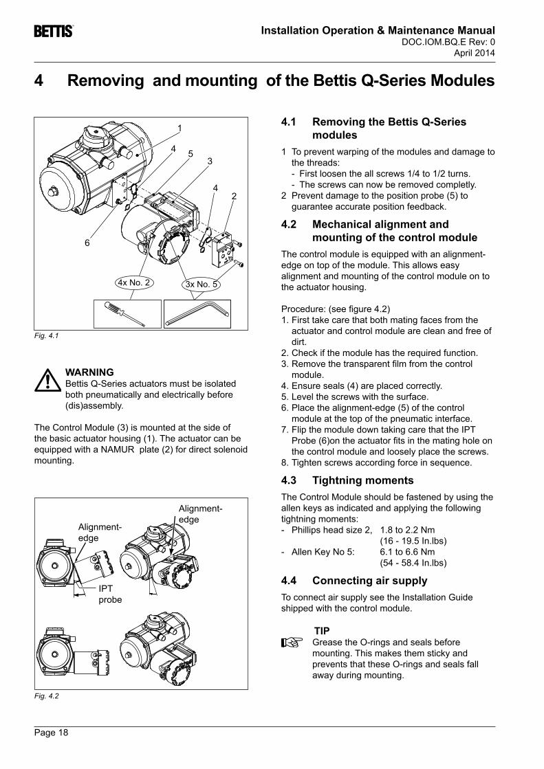
4 Removing and mounting of the Bettis Q-Series Modules
WARnInGBettis Q-Series actuators must be isolated both pneumatically and electrically before (dis)assembly.
TheControlModule(3)ismountedatthesideofthebasicactuatorhousing(1).TheactuatorcanbeequippedwithaNAMURplate(2)fordirectsolenoidmounting.
Fig. 4.1
4x No. 2 3x No. 5
1
2
34
4
5
6
4.1 Removing the Bettis Q-Series modules
1 To prevent warping of the modules and damage to the threads:
- First loosen the all screws 1/4 to 1/2 turns. - The screws can now be removed completly.2 Preventdamagetothepositionprobe(5)to
guarantee accurate position feedback.
4.2 Mechanical alignment and mounting of the control module
The control module is equipped with an alignment-edge on top of the module. This allows easy alignment and mounting of the control module on to the actuator housing.
Procedure:(seefigure4.2)1. First take care that both mating faces from the
actuator and control module are clean and free of dirt.
2. Check if the module has the required function.3.Removethetransparentfilmfromthecontrol
module. 4.Ensureseals(4)areplacedcorrectly.5. Level the screws with the surface.6.Placethealignment-edge(5)ofthecontrol
module at the top of the pneumatic interface.7. Flip the module down taking care that the IPT Probe(6)ontheactuatorfitsinthematingholeonthe control module and loosely place the screws.
8. Tighten screws according force in sequence.
4.3 Tightning momentsThe Control Module should be fastened by using the allen keys as indicated and applying the following tightning moments:- Phillips head size 2, 1.8 to 2.2 Nm (16-19.5In.lbs)
- AllenKeyNo5: 6.1to6.6Nm (54-58.4In.lbs)
4.4 Connecting air supplyTo connect air supply see the Installation Guide shipped with the control module.
TIPGrease the O-rings and seals before mounting. This makes them sticky and prevents that these O-rings and seals fall away during mounting.
Alignment-edge
Alignment-edge
IPT probe
Fig. 4.2

Page 19
Installation Operation & Maintenance ManualDOC.IOM.BQ.E Rev: 0April 2014
5 Speed control option
WARnInGBettis Q-Series actuators must be isolated both pneumatically and electrically before any(dis)assemblyisbegun.
The Bettis Q-Series can be supplied with a Speed Control option. One throttle is required for Spring Return actuators and up to two for Double Acting actuators.Thespeedcontrolthrottlecontrolstheairflowinandout of an air chamber and as such limits the speed of the “Opening” and “Closing” stroke simultaneously
5.1 Mounting Speed Control throttle(s):
1 Removetheplug(s)atthesideofthemoduleandturninthethrottle(1).
2 Spring Return actuators: Use the top entry only.3 Double acting actuators: Use both bottom and top
entries. - For standard actuators, the top entry will throttle
the closing stroke. - For standard actuators, the bottom entry will
throttle the opening stroke. - For reverse acting actuators, the opposite
strokes will be throttled.
2 Adjusting Speed Control throttle(s):
1 Removethenutcap(2).2 Clockwise rotation of the adjustment screw
reduces the speed.3 Counter clockwise rotation of the adjustment
screw increases the speed.4 Replace the nut cap.
2 1
Figure 5.1 Speed Control option
Speed Control optionO-ring seal
Speed control
Nut cover
Spring Return: Top entry only.
Double Acting: Bottom and/or top entries.
Page 20
Installation Operation & Maintenance ManualDOC.IOM.BQ.E Rev: 0
April 2014
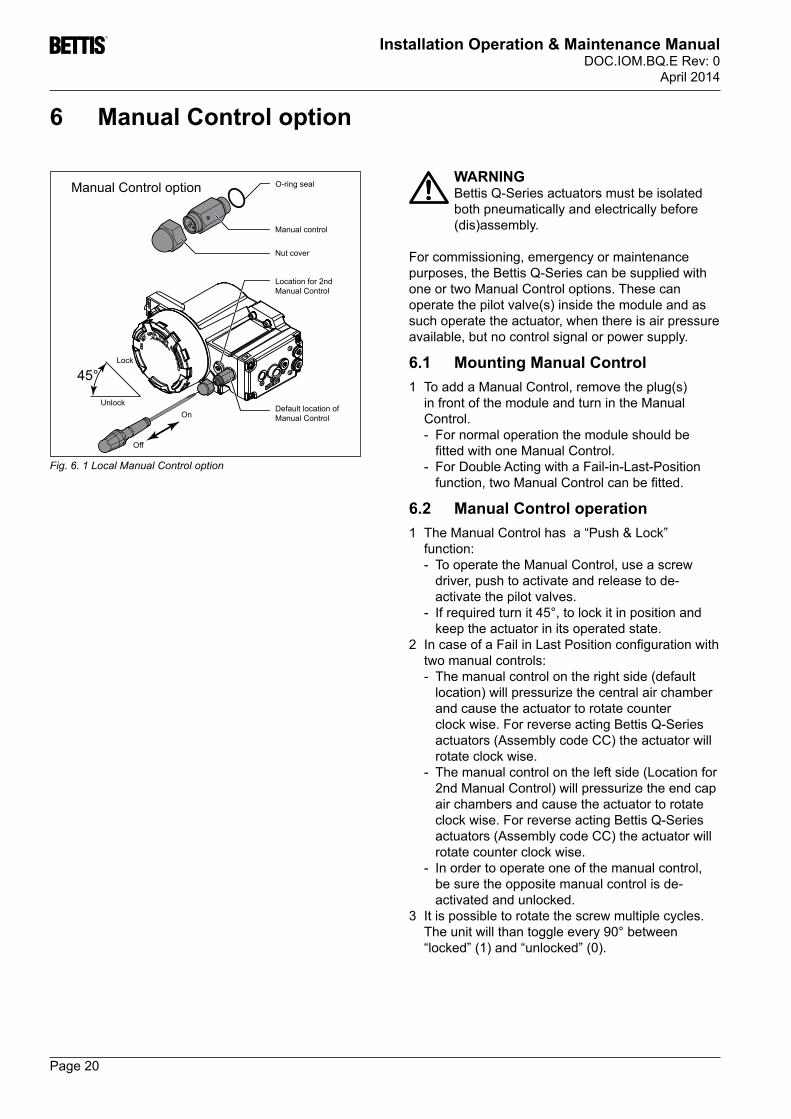
6 Manual Control option
WARnInGBettis Q-Series actuators must be isolated both pneumatically and electrically before (dis)assembly.
For commissioning, emergency or maintenance purposes, the Bettis Q-Series can be supplied with one or two Manual Control options. These can operatethepilotvalve(s)insidethemoduleandassuch operate the actuator, when there is air pressure available, but no control signal or power supply.
6.1 Mounting Manual Control1 ToaddaManualControl,removetheplug(s)
in front of the module and turn in the Manual Control.
- For normal operation the module should be fittedwithoneManualControl.
- For Double Acting with a Fail-in-Last-Position function,twoManualControlcanbefitted.
6.2 Manual Control operation1 The Manual Control has a “Push & Lock”
function: - To operate the Manual Control, use a screw
driver, push to activate and release to de-activate the pilot valves.
- If required turn it 45°, to lock it in position and keep the actuator in its operated state.
2 IncaseofaFailinLastPositionconfigurationwithtwo manual controls:
- The manual control on the right side (default location)willpressurizethecentralairchamberand cause the actuator to rotate counter clock wise. For reverse acting Bettis Q-Series actuators(AssemblycodeCC)theactuatorwillrotate clock wise.
- The manual control on the left side (Location for 2ndManualControl)willpressurizetheendcapair chambers and cause the actuator to rotate clock wise. For reverse acting Bettis Q-Series actuators(AssemblycodeCC)theactuatorwillrotate counter clock wise.
- In order to operate one of the manual control, be sure the opposite manual control is de-activated and unlocked.
3 It is possible to rotate the screw multiple cycles. The unit will than toggle every 90° between “locked”(1)and“unlocked”(0).
45°
Fig. 6. 1 Local Manual Control option
Manual Control option O-ring seal
Manual control
Nut cover
Location for 2nd Manual Control
Default location of Manual Control
Lock
UnlockOn
Off

Page 21
Installation Operation & Maintenance ManualDOC.IOM.BQ.E Rev: 0April 2014
7 Trouble shooting Bettis Q-Series7.1 Mechanical problems
Problem Possible error Solution WheretofindFeedback position and actual position are not the same.
Actuator and valve are mounted 90° rotated in relation to each other.
Remove actuator from valve. Check assembly code of actuator. Put both valve and actuator in “Closed” position. Mount actuator on valve.
Chapter 1 and 2 of DOC.IOM.BQ.E
Valve is in “Closed” position, actuator is in “Open” position and will not move anymore.
Valve does not reach the completely “Closed” or “Open” position.
Limit stop screws are not set correctly.
Readjust the limit stop screws Chapter 3 of DOC.IOM.BQ.E
Chapter 2, §2.5 of DOC.IOM.BQ. EInsert is not mounted properly Mount the insert in the right
position. Remark: Rotate insert for one cam = 22.5°
Pressure to low Apply pressure as per sizing Data sheets DA = BQ1.602.01. SR = BQ1.602.02 or BQ1.602.03
Sizing is wrong Check valve torque data with actuator torque data
Actuator rotates, valve does not.
No coupling between actuator shaft and valve spindle.
Install a coupling between actuator shaft and valve spindle.
Chapter 2 of DOC.IOM.BQ.E
7.2 Pneumatic problemsProblem Possible error Solution WheretofindActuator does not react to electrical control signal.
There is no supply pressure at the actuator.
Supply the right pressure to the actuator.
See supplied documentation of the Control Module.
Supply pressure is connected to one to the exhausts.
Connect supply pressure to port “Ps”.
See supplied documentation of the Control Module.
Actuator does not react good to electrical control signal.
Thereissufficientsupplyairpressurebutinsufficientsupply air capacity.
Take care the supply air tubing has the right dimensions.
See chapter 2, §2.6 of DOC.IOM.BQ.E
Control Module is not mounted properly.
Mount the “Control Module” in the right way to the “Pneumatic Control Module”.
See chapter 4, of DOC.IOM.BQ.E
Speedcontrol(ifpresent)blocksairflow.
Turn the speed control more open. Select 1 size larger actuator
See chapter 5 of DOC.IOM.BQ.E
Manualoverride(ifpresent)on the Control Module is locke
Unlock manual override on the Control Module.
See chapter 6 of DOC.IOM.BQ.E
Double acting actuator will only move to “open” position.
Control module has wrong pneumatic cartridge.
Replace pneumatic cartridge for version suitable for double acting actuators.
See DOC.QC4.PNC.1

Page 22
Installation Operation & Maintenance ManualDOC.IOM.BQ.E Rev: 0
April 2014
Problem Possible error Solution WheretofindActuator does not react to control signals
Control wiring, Power supply wiring or feedback wiring are not right connected.
Connect all wiring in the right way.
See documentation shipped with the Control Module. (DOC.IG.BQCxx)
The power supply voltage is not the same as the voltage of the applicable Control Module.
Connect the right power supply voltage.
See documentation shipped with the Control Module. (DOC.IG.BQCxx)
Actuator does not react consistent.
Initialization was not completed in the right way.
Execute the initialization procedure or set feedback signal manuall
See documentation shipped with the Control Module. (DOC.IG.BQCxx)
Sizing is wrong Re size the actuator to the valve
Data sheets DA = BQ1.602.01. SR = BQ1.602.02 or BQ1.602.03
There are problems with position feedback after sending the actuator to either the “Open” or “Closed” position.
The wiring of the feedback signals may be switched.
Connect the feedback wiring in the right way.
See documentation shipped with the Control Module. (DOC.IG.BQCxx)
7.3 Electrical problems

Page 23
Installation Operation & Maintenance ManualDOC.IOM.BQ.E Rev: 0April 2014
8 Maintenance
CAUTIOn: Actuatormustbeisolatedbothpneumaticallyandelectricallybeforeany(dis)assemblyisbegun.Beforemountingor(dis)assemblingtheactuatorconsulttherelevantsectionsofthismanual.
IMPORTAnTUnder the European Pressure Equipment Directive, conversion of actuators may only be performed by companies or personnel, authorized by Emerson Process Management .
8.1 GeneralAllBettisQ-Seriesactuatorsaresuppliedwithsufficientlubricationfortheirnormalworkinglife.Ifrequired,recommended lubrication for all standard actuators is a Castrol LMX, FINA Cera WR2 or equivalent. Periodic checks should be performed to make certain that all fasteners remain tight.
Depending upon the conditions under which the actuator must work such as extended duty, or abnormal operating conditions, periodic replacement of internal seals is recommended. Repair kits containing all necessary seals and instructions can be obtained through authorized Bettis Q-Series distributors.
8.2 Single acting / Spring Return actuatorsOn spring return actuators, the springs can be replaced.
SPRINGS SHOULD ALWAYS BE REPLACED IN COMPLETE SETS.
Spring kits are available through authorized Bettis Q-Series distributors.
8.3 Bettis Q-Series recommended spare partsAll soft seals, bearings, and nonreusable parts are included in the Bettis Q-Series recommended spare parts kit.The spare parts kit is identical for both the double acting and the spring return models. For the spring return mod-els we recommend a set of spare springs for each different model in addition to the recommended spare parts kit. Keepinmindthat,whennecessary,springsaretobereplacedincompletesets.Thefollowingsparepartskitsareavailable:1 Repair kit for Bettis Q-Series actuator and all modules, available per actuator size.2 Module seals kit, suitable for all module variations.
8.4 Position tracking device kitsThe position tracking device takes care of the mechanical part of the feedback signal. In case the position tracking device malfunctions, spares are available. Position tracking device kits are available per actuators size and con-tain all necessary seals and lubricants. They can be obtained through authorized Bettis Q-Series distributors.
8.5 Conversion kitsWhen the action of an actuator needs to be changed from spring return to double acting or visa versa, conversion kits can be utilized. Two kinds of conversion kits are available:1 Singleacting(springreturn)Conversionkits,tomakeaspringreturnactuator.2 Double acting Conversion kits, to make a double acting actuator.
8.6 High Temp and Low Temp Conversion kitsFor the Bettis Q-Series actuators with the NAMUR plate, special conversion kits are available to make the Bettis Q-Series suitable for High temperature or Low temperature applications. There are no “High temp” or “Low temp” conversion kits available for Bettis Q-Series actuators with modules.

Page 24
Installation Operation & Maintenance ManualDOC.IOM.BQ.E Rev: 0
April 2014
A
2
1
No. 5
sw = 10mm
12
9.1.1
9.1.2
9.1.3
9 Disassembly9.1 Before starting
9.1.1Caution! Never disassemble a valve that is under pressure!
Caution! Ball valves and plug valves can trap pressurized media in the cavity. Isolate the piping system in which the actuator valve assembly is mounted and relieve any pressure on the valve.
9.1.1 / 9.1.2Preventdamagetothepositionprobe(A)toguarantee accurate position feedback.

Page 25
Installation Operation & Maintenance ManualDOC.IOM.BQ.E Rev: 0April 2014
1
2QD
2
QS
AB
A B
9.2.1
9.2.2
9.2.3
9.2 Removing end caps all types QD and QS 40 to QS 3509.2.1
Becarefulnottodamagetheendcap(A)andB-port(B)O-rings.
9.2.2 / 9.2.3Caution! If the actuator is a “spring return” model, uniformly loosen all endcaps screws, 1/4 - 1/2 turns at a time, in sequence, to relieve pre-load of the springs.
On all actuators with springs use caution when removing endcaps.

Page 26
Installation Operation & Maintenance ManualDOC.IOM.BQ.E Rev: 0
April 2014
9.3.1
9.3.2
1 2
4
2 1
1 2
A
B
QS 600 / 950 / 1600
3
9.3.1 Becarefulnottodamagetheendcap(A)andB-port(B)O-rings.Caution! If the actuator is a “spring return” model, loosen endcap screws in sequence as shown, 1/4 - 1/2 turns at a time, to relieve pre-load of the springs.
On all actuators with springs use caution when removing endcaps.
9.3 Removing end caps type QS 600 to 1600
Page 27
Installation Operation & Maintenance ManualDOC.IOM.BQ.E Rev: 0April 2014
2
21
9.4.1
9.4.3
9.4.2
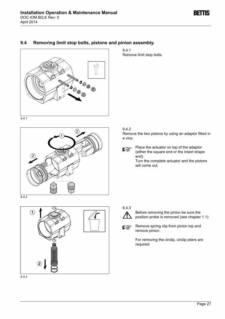
9.4.1 Remove limit stop bolts.
1
2
9.4.2 Removethetwopistonsbyusinganadaptorfittedina vice.
Place the actuator on top of the adaptor (either the square end or the insert shape end).Turn the complete actuator and the pistons will come out.
9.4.3Before removing the pinion be sure the positionprobeisremoved(seechapter1.1)
Remove spring clip from pinion top and remove pinion.
For removing the circlip, circlip pliers are required.
9.4 Removing limit stop bolts, pistons and pinion assembly.

Page 28
Installation Operation & Maintenance ManualDOC.IOM.BQ.E Rev: 0
April 2014
9.4.5
3
1
2
9.4.4
9.4.4Remove spring clip form upper pinion part and remove upper pinion part through bore of housing
For removing the circlip, circlip pliers are required.
9.4.5
Removing the insert requires an extraction tool. Please contact your local Bettis Q-Series representative for more information about this extraction tool.

Page 29
Installation Operation & Maintenance ManualDOC.IOM.BQ.E Rev: 0April 2014
10.1.1
10 Reassembly10.1 Reassembly guide band and pinion assembly
14
1
1 1
1
5
5
6
6
2
3
15
9
8
13
4
7 710
1
1112
14
CASTROL LMX or FINA CERAN WR2(or equal)
Before reassembly check the requested assemblycode(seechapter2.7).
10.1.1Apply grease to the parts as per table 10.1 and figure10.1.1
Table 10.1 Grease instructions
Part Section of part Amount of greaseO-rings1 Completely LightfilmHousing2 Piston bore Lightfilm3 Top pinion bore Lightfilm4 Bottom pinion bore LightfilmPistons
5O-ring & guideband groove
Fully greased
6 Outer side of legs Lightfilm
7 Gear teethHalf the teeth depth full with grease
Pinion8 Bottom O-ring groove Fully greased9 Top O-ring groove Lightfilm
10 Gear teethHalf the teeth depth full with grease
Upper pinion part11 Outer diameter Fully greased12 Inner diameter LightfilmHousing guideband 13 Inner diameter LightfilmPiston Guidebands 14 Completely Lightfilm
Important: Do not grease the middle part of the piston bore(15)andtheouterdiameterofthehousing guideband .
Take care that half the gear depth is full with grease.

Page 30
Installation Operation & Maintenance ManualDOC.IOM.BQ.E Rev: 0
April 2014
10.1.2
10.1.3
1
23
1
23
Code CW
Code CC
12
1
2
A
B
C
F
E
10.1.2 1. Mounttheupperpinionpart(A),2. Mountthestrokeadjustmentcam(B)and
housingguideband(C).
Keepthestrokeadjustmentcaminpositionwhile mounting the pinion.
The two circlips have one side with bevelled edges(E)whichmustgoDOWNontothethrustwasher,thesquareedgeside(F)mustface UPWARDS.
10.1.3Mount the pinion.
For fastening the circlips, circlip pliers are required.
Uselimitstopscrews(3)asareferencetopositionlimitstopcam(1)andpinion(2)asshown. See indication dot in the Pinion top slot. Views are from above.
The position of the pinion and the limit stop cam, as shown, is the position where the pistons are in the inward position (see next paragraph).

Page 31
Installation Operation & Maintenance ManualDOC.IOM.BQ.E Rev: 0April 2014
10.2.2
10.2.3
12
21
a
ba = b
= Code CW
CASTROL LMX or FINA CERAN WR2(or equal)
a a = b
b
= Code CC
CASTROL LMX or FINA CERAN WR2(or equal)
c dc=d
ok !
ok !
90°
10.2.1
10.2 Reassemble the pistons10.2.1 / 10.2.21 Check required assembly code.2 Applyalightfilmofgreasetotheboreofthe
housing.3 EnsurethatO-rings(1)andguidebands(2)are
kept in place during assembly.4 Align the pinion so that the teeth on the pinion will
“pickup” the pistons rack teeth when turning the top of the pinion:
- clockwise(CW)forassemblycodeCWor - counterclockwise(CCW)forassemblycodeCC
Turn the pinion gently to guide the guide band into the housing, taking care not to damage the guide band.
10.2.3Ensure that smooth movement and 90 degree operation can occur without moving the pistons out of the actuator body.Ensure that the slot on the pinion top is:- exactlyperpendicular(codeCW)or- inline(codeCC)withtheactuatorscentre
line. If not, turn the pistons outward until they disengage from the pinion. Shift one tooth of the pinion, reassemble and check again.

Page 32
Installation Operation & Maintenance ManualDOC.IOM.BQ.E Rev: 0
April 2014
N-1 N-2
N-3 N-4
N-5 N-6
1
2
10.3.3
10.3.2
10.3.1
CASTROL LMX or FINA CERAN WR2(or equal)
10.3 Reassembly end caps, all types QD and QS 40 to QS 35010.3.1When replacing springs in a spring return actuator, ensure that the springs are replaced in their identical position in the spring pack from where they were removed. Before assembling the springs and endcaps, make sure that the pistons are inwards.
10.3.2Put some grease on the endcap O-ring before mounting.
10.3.3EnsurethatendcapO-rings(1)andairportO-rings(2)areinplaceonbothsides.
PutsomegreaseontheairportO-rings(2),so they and stay in place while mounting.

Page 33
Installation Operation & Maintenance ManualDOC.IOM.BQ.E Rev: 0April 2014
1 1
22 1
1 2
QS 600 / 950 / 1600
2
b
10.4.1
10.4.2
N-1 N-2
N-3 N-4
N-5 N-6
a
10.4.2EnsurethatendcapO-rings(a)andairportO-rings(b)areinplaceonbothsides.
Engage the bolts with the tapped holes in the actuator body by forcing down slightly on the cap. Tighten each bolt in small and equal turns.
Table 10.3 Tightening torque Bettis Q-Series end-cap bolts
Actuator Type
Cap Bolt Size
Hexagon Key size
Tightening Torque
nm in.lb
max. min. max. min.
40 M5 4mm 1,7 1,3 15 1165 M6 5 mm 3,2 2,7 28 24100 M6 5mm 3,2 2,7 28 24200 M8 6mm 7,1 5,2 63 46350 M10 8mm 14 11,2 124 99600 M12 10mm 44,2 25 391 222950 M12 10mm 44,2 25,1 391 2221600 M14 12mm 70,6 39,6 624 350
10.4 Reassembly end caps single acting actuators QS 600 to QS 160010.4.1When replacing springs in a spring return actuator, ensure that the springs are replaced in their identical position in the endcap from where they were removed. Before assembling the springs and endcaps, make sure that the pistons are inwards.

Page 34
Installation Operation & Maintenance ManualDOC.IOM.BQ.E Rev: 0
April 2014
2
A
B
10.5.1
10.5.2
10.5.3
10.5 Mounting and setting of limit stopsSetting of limit stops
Closed position1 Move actuator to the “Closed” position(1.2 Turn the “Closed” limit stop screw in until it blocks.3 Move actuator to the “Open” position(1.4 Turn the “Closed” limit stop screw in as shown in
table 2.5.2
Open position1 Repeat the steps 1 to 4 as described for the
“Closed” position but now for the “Open” position.
(1 Apply pressure to port A or B
REMARKThis procedure does not apply for setting the exact end positions of a “Bettis Q-Series mounted on a valve”. To set the end positions of a Bettis Q-Series mounted on a valve, do as described above, check the valve position and adjust where necessary.
Table 3.1 Angular Displacment & ToolsActuator
Size
Angular
displacement
Tools
nut Bolt
Q40 3.0 ° W10 mm SD1.2 mmQ65 3.6 ° W13 mm SD1.2 mmQ100 2.7 ° W13 mm SD1.2 mmQ150 2.7 ° W17 mm SD1.5 mmQ200 2.3 ° W17 mm SD1.5 mmQ350 2.7 ° W19 mm SD1.5 mmQ600 2.7 ° W24 mm W10 mmQ950 2.5 ° W24 mm W10 mmQ1600 2.7 ° W30 mm W10 mm
W = Wrench
SD = Screwdriver

Page 35
Installation Operation & Maintenance ManualDOC.IOM.BQ.E Rev: 0April 2014
M12x1.5
1
2
3
Code CW Code CC
10.6.2
10.6.3
10.6.1
10.6 Final assembly and airtightness test10.6.1PlugtheIPTdevicehole(1)withaM12x1.5plug.Applypressure(max.8barg/116PSI)toports(2)and(3).Usesomesoapsudsattheindicatedpoints.
Applying pressure to the actuator will cause the actuator/valve assembly to operate.
In case of leakage around :1 The limit stop bolts (and/or the spring-package-boltatspringreturnmodels):
- Turn the lock nut of the bolts tighter, until leakage stops.
2 The endcaps : - Disassemble the endcaps, replace O-rings and
reassemble the endcaps.3 The pinion top or bottom and A- or B-port: - Disassemble the complete actuator, replace
O-rings and reassemble the actuator.
10.6.2Take care that the position probe and the mounting holeisclean.ApplyCastrolCLSgreasetothetip(1)to ensure proper functioning.
sw = 10mm
1
CASTROL CLS(or equal)
10.6.3Check the position of the inner part of the position indication knob. When mounted to the pinion top, the projectionoftheinnerpartwillfitinthegrooveonthe pinion top.To disassemble the inner part, press as shown.
For assembly of the Controlmodules see Chapter 4

Page 36
Installation Operation & Maintenance ManualDOC.IOM.BQ.E Rev: 0
April 2014
1
10
37
47
912
38
42
40
36 41
15
11 8
14
17
18
19
20
21
3233
3429
35
432
3839
44
4648
45 49
15 13 50 20 19 18 17
13
1011
12
51
52
39
76
54
32
11 Bettis Q-Series Parts11.1 ExplodedviewBettisQ-Series(baseactuator)

Page 37
Installation Operation & Maintenance ManualDOC.IOM.BQ.E Rev: 0April 2014
11.2 Bill Of Material
Pos. Qty. Description note
1 1 Body2 2 Washer 13 1 Circlip 14 1 Circlip 15 1 Indicator insert6 1 Indicator knob7 1 Indicator arrow8 1 Screw9 1 Guideband(housing) 1
10 2 Piston11 2 O-ring(piston) 112 2 Guideband(piston) 113 8 End cap screws14 2 End cap QD15 2 O-ring(Endcap) 117 4 Nut cover18 4 Nut19 4 Washer limit stops 120 4 O-ring(limitstops) 121 2 Limit stop screw29 1 O-ring(NAMURplateIPTport) 2
Pos. Qty. Description note
32 3 Screw33 1 NAMUR plate34 1 O-ring(NAMURplate) 235 1 O-ring(NAMURplate) 236 1 O-ring(piniontop) 137 1 Pinion38 2 Bearing ring 139 2 O-ring(pinion) 140 1 Insert41 2 O-ring(B-port) 142 1 Limitstop cam43 1 Upper pinion part44 2 Springpackbolt(QS)45 2 Washer46 2 Spring retainer47 2 Outer spring48 2 Middle spring49 2 Inner spring50 2 End cap QS51 2 O-ring52 1 Center plate 3
nOTES1. Included in repair kits for the actuator2. Included in seal kit for the modules and NAMUR plate.3. Options4.SomeactuatorsizehaveasteelballtoclosetheB-portinsteadofO-ringB-port(41)

Page 38
Installation Operation & Maintenance ManualDOC.IOM.BQ.E Rev: 0
April 2014
11.3ExplodedviewBettisQ-Series(Controlmodule)
1234 56 7
8
9
1011
13
14
12
151617
201918
22 23
Pos. qty Description
1 1 Module Housing2 1 Pilot valve Cartridge3 1 Switch cartridge4 1 Cover5 1 Cover seal6 1 Cover lock screw7 1 Blind plug8 1 Pneumatic compartment cover9 1 Pneumatic compartment cover seal10 1 Module to Actuator O-ring seal (111 1 Module to Actuator O-ring seal (112 3 Module fastening screws and washers13 1 Pneumatic cartridge14 1 Pneumatic cartridge seal15 1 Shield switch adjustment screws16 1 Manualcontrol(option)17 2 Manualcontrolblindplug(default)18 1/2 Silencer(1xSR,2xDA)19 0/1 Exhaustblindplug(0xDA,1xSR)20 2 Speed control blind plug22 1 IPT device23 1 O-ring seal IPT port (1
nOTES1. Included in seal kit for the modules and NAMUR plate.

Page 39
Installation Operation & Maintenance ManualDOC.IOM.BQ.E Rev: 0April 2014

w w w . Bettis. c o m
WorldAreaConfigurationCenters(WACC)offersalessupport,service, inventory and commissioning to our global customers. ChoosetheWACCorsalesofficenearestyou:
www.emersonprocess.com/bettis
All Rights Reserved. We reserve the right to modify or improve the designs or specificationsoftheproductsmentionedinthismanualatanytimewithout notice. Emerson Process Management does not assume responsibility for the selection, use or maintenance of any product. Responsibility for proper selection, use and maintenance of any Emerson Process Management product remains solely with the purchaser. ©2014 Emerson Electric Co.
North & South AmericA 19200 Northwest Freeway Houston, TX 77065 T +1 281 477 4100 F +1 281 477 2809Av. Hollingsworth, 325, Iporanga Sorocaba, SP 18087-105 Brazil T +55 15 3238 3788 F +55 15 3228 3300
ASiA PAcific No. 9 Gul Road #01-02 Singapore 629361 T +65 6501 4600 F +65 6268 0028 No.1 Lai Yuan Road Wuqing Development Area Tianjin 301700 P.R.China T +86 22 8212 3300 F +86 22 8212 3308
middle eASt & AfricA P. O. Box 17033 Dubai United Arab Emirates T +971 4 811 8100 F +971 4 886 5465
P. O. Box 10305 Jubail 31961 Saudi Arabia T +966 3 340 8650 F +966 3 340 8790
24 Angus Crescent Longmeadow Business Estate East P.O. Box 6908; Greenstone; 1616 Modderfontein, Extension 5 South AfricaT +27 11 451 3700F +27 11 451 3800
euroPe Asveldweg 11 7556BRHengelo(O) The Netherlands T +31 74 256 1010 F +31 74 291 0938
For complete list of sales and manufacturing sites, please visit www.emersonprocess.com/valveautomationlocations Or contact us at [email protected]