beverage duty, food duty, and poultry duty speed … · beverage duty, food duty, and poultry duty...
TRANSCRIPT

STOBER Drives Inc. • BD2004 • www.stober.com • 1
Beverage Duty, Food Duty, and Poultry Duty MGS® Speed Reducers
Table of Contents
"K" Series – Beverage Duty and Food Duty
Features ....................................... 2Double Bushing Unit .................... 4Single Side Output Shaft Unit ..... 6Torque Arm Brackets .................. 8Torque Arm .................................. 9Bushing Installation ................... 10Mounting Information ................. 12
"C" Series – Beverage Duty and Food Duty
Features ..................................... 15Dimensions ................................ 16
"F" Series – Poultry Duty
Features ..................................... 18Dimensions ................................ 19
"K" Series – Poultry Duty
Features ..................................... 20Dimensions ................................ 21
Mission Statement ..................... 14Motor Mounting Instructions ...... 22Terms and Conditions of Sale ... 24
STOBER's MGS® Beverage, Food, and Poultry duty product offerings havebecome the quality standard for the markets served. These robust solutions forextreme environments leverage precision helical bevel gearing to achieve thehighest efficiency, therefore, reducing your operating and maintenance cost.These reducers excel in extremely demanding applications under the harshestwashdown environments.
The basic features include:• Three year warranty.• Maintenance free.• Lubricated for life.• Double sealed output.• High tensile 300 series stainless steel quill, bushing, shafts, and fasteners.• Mounts in any position with output shaft horizontal.• Wash down covers for all output configurations.• Multilayered industrial strength epoxy coating with 316 stainless steel
leafing pigments.
Company ProfileSTÖBER has been a pioneer in the gearing industry since 1934. Throughconstant innovation, STÖBER today is known for high performance, highefficiency, and low noise, encompassing various gearing solutions offered to theindustry. STOBER® Drives Incorporated, located in Maysville KY, manufacturesproducts for the North American market.
Beginning with the ComTrac® Mechanical Variable Speed Reducer, STÖBERestablished itself as a technology innovator, later adding the reliable constantspeed MGS® series to broaden the product offering. The MGS (Modular GearSystem) line provides a large range of available sizes, ratios, mounting flexibility,and extremely responsive delivery options.
STÖBER next introduced ServoFit® Precision Planetary Gearheads – setting thestandard for low noise and low backlash in the servo industry. The SMS(ServoFit® Modular System) combines the proven excellence of the MGSsystem with servo precision to create a cost effective alternative in the servomarket.
STÖBER has the broadest product offering available, providing one stopshopping for both the industrial gearing market and the rapidly growing motioncontrol market.
On behalf of the world wide STÖBER Team, we pledge to meet or exceed yourproduct and service needs with continued high quality solutions.
Sincerely,
Bernd Stöber, Chairman
STÖBER Antriebstechnik GmbH
Peter Feil, VP/General Manager
STOBER Drives, Inc.

2 • STOBER Drives Inc. • BD2004 • www.stober.com
Beverage Duty and Food Duty"K" Series – MGS Helical/Bevel Reducers
The standard "K" Series Helical/Bevel MGS Beverage Duty and FoodDuty unit is supplied with a patented double sided wobble freebushing system. This unique design allows the unit to be mounted onthe shaft from either side of the reducer (see illustration below).Featuring a distinct support side and a clamp side, the dual taperedcones will overcome a wide range of tolerances normally found withstandard shaft materials. The clamp side is determined by thecustomer but is usually the outside bushing.
Each case size can be provided with a variety of bushing bore sizes.The unit is selected based on horsepower or torque rating, outputspeed or ratio, and the shaft size of the driven equipment. Thebushing is not installed into the unit at the factory, but with easy tofollow assemble instructions, the unit and bushing can be mounted onthe machinery quickly – without any special tools. The bore size in theunit can be changed any time during the life of the unit simply bychanging the bushing kit.
This unit has several features that make it virtually maintenance freein a wet or dry environment.
• All quills and bushing parts are high tensile stainless steel–allowing the same torque capacity as the standard MGS unit withthe additional benefit of corrosion resistance.
• The output is double sealed on both sides using an outer dual lipseal and an inner single lip seal.
• The NEMA C-face input flange has an O-ring between thereducer and motor.
• Each unit is shipped with Grade 5EP oil filled to the proper levelto mount in any position with the output horizontal. Food gradeoil can be provided upon request.
• All units are supplied with output covers which protect the sealsduring washing and also cover the rotating bushings. Theoutside cover also has an O-ring for added protection.
• Since all units are completely sealed, they are lubricated for life.There is no breather that can allow moisture to enter the unitduring high pressure washing.
• All hardware is stainless steel.
• Stainless steel coating – each unit is coated in multiple steps toinsure robustness for your demanding applications. This uniquecoating incorporates 316 stainless steel leafing pigments into thecoating. Food Duty units have two additional layers of epoxycoating to achieve the required resistance levels for yourextreme washdown conditions. The finish is USDA approved foruse in food processing and handling.
In addition, all units can be provided, on request, with a clearcoat or white epoxy topcoat which is also USDA approved.
• All STOBER MGS reducers have a three year warranty.
• "K" Series units can also be supplied for Food and BeverageDuty with a single side stainless steel output shaft.
Bushing on Both SidesInterchangeable Support Side and Clamp Side
Clamp Support Support ClampSide Side Side Side
Conveyor with Shaft Either Side
ComparisonBEVERAGE DUTY FOOD DUTY
Coating: Industrial 316 Stainless Steel Epoxy Multilayer Industrial 316 Stainless Steel Epoxy
Output: Stainless Steel Stainless Steel
Key: Stainless Steel Stainless Steel
Seals: Double Double1- Dual Lip Outer Output Seal 1- Dual Lip Outer Output Seal1- Single Lip Inner Output Seal 1- Single Lip Inner Output Seal
Hardware: ALL Stainless Steel ALL Stainless Steel
Lubricant: Standard (Mobile 630) Standard (Mobile 630)
Options: Food Grade Oil (Exxon Univis Special Mist 220) Food Grade Oil (Exxon Univis Special Mist 220)Synthetic Oil (Mobil SHC630) Synthetic Oil (Mobil SHC630)
Ultra Clear Industrial Epoxy Ultra Clear Industrial EpoxyWhite Epoxy White Epoxy

STOBER Drives Inc. • BD2004 • www.stober.com • 3
Beverage Duty and Food Duty"K" Series – MGS Helical/Bevel Reducers
ALL Stainless Steel Hardware
Patented(1) Stainless Steel Double Sided Bushing Mounted intoStainless Steel Output Quill – easily mounts onto standard coldfinished, ground, or stainless shafting.
Double Sealed Output – with a dual lip outer seal and a single lipinner seal
Stainless Steel Nameplate
Watertight Outside Closed Cover Cap –protects seals from high pressure washing
Inside Split Cover Cap – enableseasy assembly onto the shaft
• Lubricated for Life• Maintenance Free• Totally Enclosed (Watertight)• 3 Year Warranty – your guarantee of our confidence in the MGS (Modular Gear System) line of reducers• 97% Efficiency – for high quality and reliability plus cost savings in energy and maintenance
Indicates Beverage Duty.Indicates Food Duty.
NEMA C-face Input• O-ring between the motor
and reducer• Easy mount maintenance
free coupling
(1) U.S. Patent Number 5,496,127
Standard Coating – Industrial 316 Stainless Steel Epoxy– Multilayer Industrial 316 Stainless Steel Epoxy
Coating Options – Additional Layer Ultra Clear Industrial Epoxy– White Epoxy
Mounting PositionsOne Standard Unit for ALL Horizontal Mounting Positions Without Changing the Oil Level
EL1 EL2 EL5 EL6Possible but not recommended
4 • STOBER Drives Inc. • BD2004 • www.stober.com
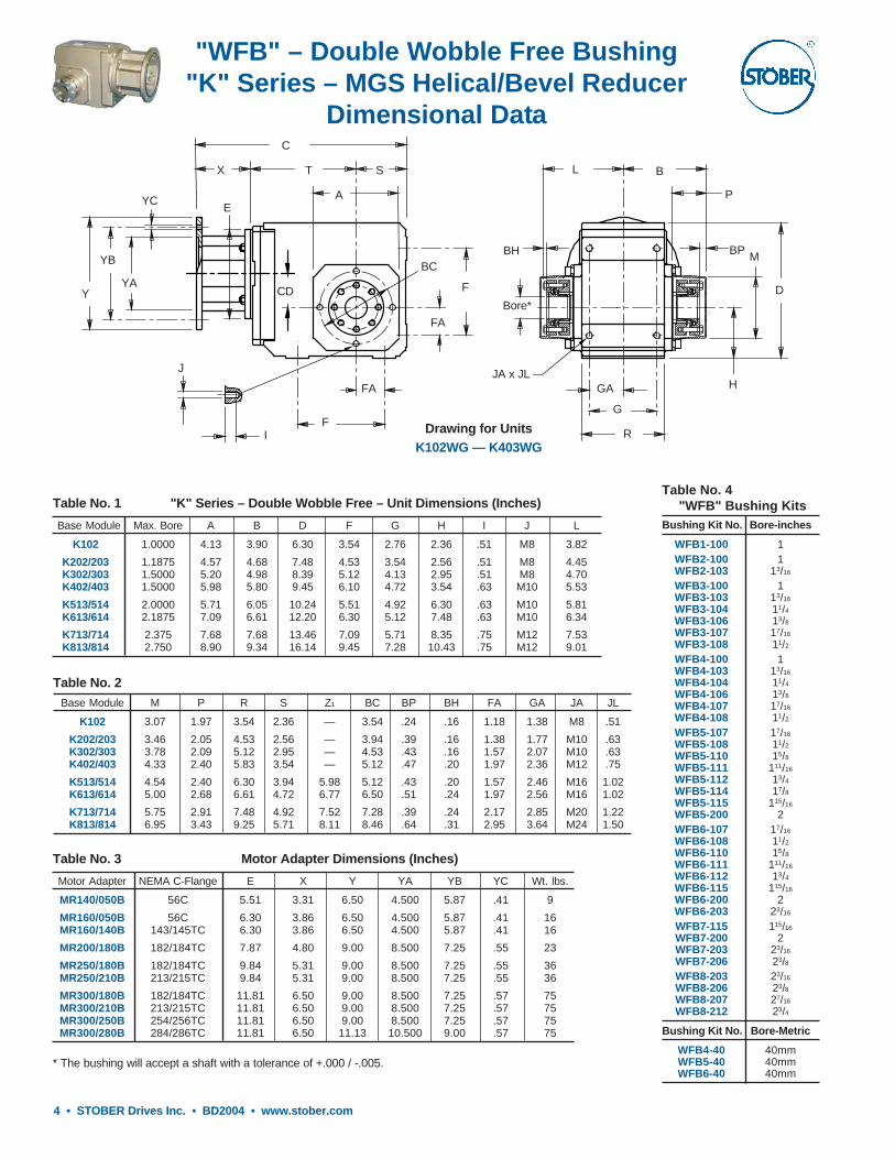
"WFB" – Double Wobble Free Bushing"K" Series – MGS Helical/Bevel Reducer
Dimensional Data
J
I
E
C
S
FA
F
Drawing for UnitsK102WG — K403WG
L
Y
YB
YA
YC A
CD
X T
Bore*
GA
B
P
R
G
H
D
M
FA
F
BCBPBH
JA x JL
Table No. 4 "WFB" Bushing Kits
Bushing Kit No. Bore-inches
WFB1-100 1WFB2-100 1WFB2-103 13/16
WFB3-100 1WFB3-103 13/16
WFB3-104 11/4
WFB3-106 13/8
WFB3-107 17/16
WFB3-108 11/2
WFB4-100 1WFB4-103 13/16
WFB4-104 11/4
WFB4-106 13/8
WFB4-107 17/16
WFB4-108 11/2
WFB5-107 17/16
WFB5-108 11/2
WFB5-110 15/8
WFB5-111 111/16
WFB5-112 13/4
WFB5-114 17/8
WFB5-115 115/16
WFB5-200 2WFB6-107 17/16
WFB6-108 11/2
WFB6-110 15/8
WFB6-111 111/16
WFB6-112 13/4
WFB6-115 115/16
WFB6-200 2WFB6-203 23/16
WFB7-115 115/16
WFB7-200 2WFB7-203 23/16
WFB7-206 23/8WFB8-203 23/16
WFB8-206 23/8WFB8-207 27/16
WFB8-212 23/4
Bushing Kit No. Bore-Metric
WFB4-40 40mmWFB5-40 40mmWFB6-40 40mm
Table No. 1 "K" Series – Double Wobble Free – Unit Dimensions (Inches)
Base Module Max. Bore A B D F G H I J L
K102 1.0000 4.13 3.90 6.30 3.54 2.76 2.36 .51 M8 3.82
K202/203 1.1875 4.57 4.68 7.48 4.53 3.54 2.56 .51 M8 4.45K302/303 1.5000 5.20 4.98 8.39 5.12 4.13 2.95 .51 M8 4.70K402/403 1.5000 5.98 5.80 9.45 6.10 4.72 3.54 .63 M10 5.53
K513/514 2.0000 5.71 6.05 10.24 5.51 4.92 6.30 .63 M10 5.81K613/614 2.1875 7.09 6.61 12.20 6.30 5.12 7.48 .63 M10 6.34
K713/714 2.375 7.68 7.68 13.46 7.09 5.71 8.35 .75 M12 7.53K813/814 2.750 8.90 9.34 16.14 9.45 7.28 10.43 .75 M12 9.01
Table No. 2Base Module M P R S Z1 BC BP BH FA GA JA JL
K102 3.07 1.97 3.54 2.36 — 3.54 .24 .16 1.18 1.38 M8 .51
K202/203 3.46 2.05 4.53 2.56 — 3.94 .39 .16 1.38 1.77 M10 .63K302/303 3.78 2.09 5.12 2.95 — 4.53 .43 .16 1.57 2.07 M10 .63K402/403 4.33 2.40 5.83 3.54 — 5.12 .47 .20 1.97 2.36 M12 .75
K513/514 4.54 2.40 6.30 3.94 5.98 5.12 .43 .20 1.57 2.46 M16 1.02K613/614 5.00 2.68 6.61 4.72 6.77 6.50 .51 .24 1.97 2.56 M16 1.02
K713/714 5.75 2.91 7.48 4.92 7.52 7.28 .39 .24 2.17 2.85 M20 1.22K813/814 6.95 3.43 9.25 5.71 8.11 8.46 .64 .31 2.95 3.64 M24 1.50
* The bushing will accept a shaft with a tolerance of +.000 / -.005.
Table No. 3 Motor Adapter Dimensions (Inches)
Motor Adapter NEMA C-Flange E X Y YA YB YC Wt. lbs.
MR140/050B 56C 5.51 3.31 6.50 4.500 5.87 .41 9
MR160/050B 56C 6.30 3.86 6.50 4.500 5.87 .41 16MR160/140B 143/145TC 6.30 3.86 6.50 4.500 5.87 .41 16
MR200/180B 182/184TC 7.87 4.80 9.00 8.500 7.25 .55 23
MR250/180B 182/184TC 9.84 5.31 9.00 8.500 7.25 .55 36MR250/210B 213/215TC 9.84 5.31 9.00 8.500 7.25 .55 36
MR300/180B 182/184TC 11.81 6.50 9.00 8.500 7.25 .57 75MR300/210B 213/215TC 11.81 6.50 9.00 8.500 7.25 .57 75MR300/250B 254/256TC 11.81 6.50 9.00 8.500 7.25 .57 75MR300/280B 284/286TC 11.81 6.50 11.13 10.500 9.00 .57 75

STOBER Drives Inc. • BD2004 • www.stober.com • 5
"WFB" – Double Wobble Free Bushing"K" Series – MGS Helical/Bevel Reducer
Dimensional Data
Part No. ExampleBeverage Duty Unit
with 143TC Frame Motor Adapter and 17/16 Bushing BoreK303WG0650 MR160/140B WFB3-107
Drawing for UnitsK513WG — K614WG
F
FA
Z1
I
J
A
S
YC
YA
X
C
YB
CD
F
FABore *
GA
G
M
D
BP
B
R
L
H
BC
T
Y
EBH
P
JA
1) Also available as MR160/050B for a NEMA 56C frame motor.2) Also available as MR250/180B for a NEMA 182/184TC frame motor.3) Also available as MR300/180B for a NEMA 182/184TC, MR300/210B for a
NEMA 213/215TC, and MR300/280B for a NEMA 284/286TC frame motor.All weights are approximate.
Table No. 5 "K" Series – Double Wobble Free – Unit Dimensions (Inches)
Base MR140/050B MR160/140B 1) MR200/180B MR250/210B 2) MR300/250B 3) Wt.
Module CD C T CD C T CD C T CD C T CD C T lbs.
K102 1.42 10.55 4.88 1.42 11.26 5.04 — — — — — — — — — 31
K202 1.81 11.50 5.63 1.81 12.21 5.79 1.81 13.23 5.87 — — — — — — 40K203 1.81 12.96 7.09 — — — — — — — — — — — — 53
K302 2.07 12.68 6.42 2.07 13.38 6.57 2.07 14.40 6.65 — — — — — — 67K303 2.07 14.13 7.87 .63 15.08 8.27 — — — — — — — — — 73
K402 — — — 2.36 14.76 7.36 2.36 15.74 7.44 2.36 16.41 7.56 — — — 93K403 2.36 15.51 8.66 .91 16.46 9.06 — — — — — — — — — 100
K513 — — — .59 14.57 6.77 .59 15.59 6.85 .59 16.22 6.97 — — — 106K514 — — — .59 16.26 8.46 — — — — — — — — — 109
K613 — — — .71 16.10 7.52 .71 17.12 7.60 .71 17.75 7.72 .71 19.49 8.27 170K614 — — — .71 17.79 9.21 — — — — — — — — — 177
K713 — — — — — — .79 18.42 8.70 .79 19.05 8.82 .79 20.75 9.33 221K714 — — — .79 19.13 10.35 .79 20.86 11.14 — — — — — — 234
K813 — — — — — — .94 20.23 9.72 .94 20.82 9.80 .94 22.52 10.31 309K814 — — — — — — .94 22.64 12.13 — — — — — — 331
Table No. 6 "WFB" Bushing – Stock Bores
Base INCHES METRIC
Module 1 13/16 11/4 13/8 17/16 11/2 15/8 111/16 13/4 17/8 115/16 2 23/16 23/8 27/16 23/4 40mm
K102 x — — — — — — — — — — — — — — — —
K202/K203 x x — — — — — — — — — — — — — — —K302/K303 x x x x x x — — — — — — — — — — —K402/K403 x x x x x x — — — — — — — — — — x
K513/K514 — — — — x x x x x x x x — — — — xK613/K614 — — — — x x x x x — x x x — — — xK713/K714 — — — — — — — — — — x x x x — — —K813/K814 — — — — — — — — — — — — x x x x —

6 • STOBER Drives Inc. • BD2004 • www.stober.com
Single Side Output Shaft"K" Series – MGS Helical/Bevel Reducer
Dimensional Data
CD
F
UA
Drawing for UnitsK102VG — K403VG
YC
YBE
FA
UBS
YA
X
R
V
H
D
G
GA
U
F
FA
J Dia. x I Deep4 Places Side 1 and
4 Places Side 5(K1 is 4 Places onSide 1, 2, and 5)
Y
C
T
P
L
QU
Table No. 3 Motor Adapter Dimensions (Inches)
Motor Adapter NEMA C-Flange E X Y YA YB YC Wt. lbs.
MR140/050B 56C 5.51 3.31 6.50 4.500 5.87 .41 9
MR160/050B 56C 6.30 3.86 6.50 4.500 5.87 .41 16MR160/140B 143/145TC 6.30 3.86 6.50 4.500 5.87 .41 16
MR200/180B 182/184TC 7.87 4.80 9.00 8.500 7.25 .55 23
MR250/180B 182/184TC 9.84 5.31 9.00 8.500 7.25 .55 36MR250/210B 213/215TC 9.84 5.31 9.00 8.500 7.25 .55 36
MR300/180B 182/184TC 11.81 6.50 9.00 8.500 7.25 .57 75MR300/210B 213/215TC 11.81 6.50 9.00 8.500 7.25 .57 75MR300/250B 254/256TC 11.81 6.50 9.00 8.500 7.25 .57 75MR300/280B 284/286TC 11.81 6.50 11.13 10.500 9.00 .57 75
Optional OutputCover
BC
A
B
Table No. 1 "K" Series – Unit Dimensions (Inches) – "G" Housing Style
Base Module A B BC D F FA G GA H I J L O P R
K102 4.13 4.17 2.64 6.30 3.54 1.18 2.76 1.38 2.36 .51 M8 4.53 — 2.32 3.54K202/203 4.57 5.28 3.23 7.48 4.53 1.38 3.54 1.77 2.56 .63 M10 5.31 — 2.56 4.53
K302/303 5.20 5.75 3.46 8.39 5.12 1.57 4.13 2.07 2.95 .63 M10 5.59 — 2.60 5.12K402/403 5.98 6.81 4.08 9.45 6.10 1.97 4.72 2.36 3.54 .75 M12 6.54 — 3.39 5.83
K513/514 5.71 7.28 4.31 10.24 5.51 1.57 4.92 2.46 6.30 1.02 M16 8.74 5.10 3.90 6.30K613/614 7.09 7.87 4.61 12.20 6.30 1.97 5.12 2.56 7.48 1.02 M16 9.29 5.35 4.31 6.61
K713/714 7.68 8.90 5.08 13.46 7.09 2.17 5.71 2.85 8.35 1.22 M20 10.91 6.46 5.14 7.48K813/814 8.90 11.10 6.26 16.14 9.45 2.95 7.28 3.64 10.43 1.50 M24 12.83 7.28 5.94 9.25
Table No. 2
Base Module Q S U UA – Key UB V Z1
K102 .16 2.36 1.000 1/4 × 1/4 × 19/16 1.11 1.97 —K202/203 .16 2.56 1.250 1/4 × 1/4 × 115/16 1.36 2.36 —
K302/303 .16 2.95 1.250 1/4 × 1/4 × 115/16 1.36 2.36 —K402/403 .16 3.54 1.375 5/16 × 5/16 × 25/16 1.51 2.76 —
K513/514 .16 3.94 1.750 3/8 × 3/8 × 35/32 1.92 3.54 5.98K613/614 .16 4.72 1.750 3/8 × 3/8 × 35/32 1.92 3.94 6.77
K713/714 .16 4.92 2.375 5/8 × 5/8 × 315/16 2.65 4.72 7.52K813/814 .20 5.71 2.875 3/4 × 3/4 × 45/16 3.21 5.51 8.11

STOBER Drives Inc. • BD2004 • www.stober.com • 7
Single Side Output Shaft"K" Series – MGS Helical/Bevel Reducer
Dimensional Data
Drawing for UnitsK513VG — K814VG
F
Z1
CD
E
YC
UBC
YYA
GA
G
OptionalOutputCover
H
D
U
R
BC
L
O
P
V
Q
U
T SX
UA
F
FA
B
YB FA
1) Also available as MR160/050B for a NEMA 56C frame motor.2) Also available as MR250/180B for a NEMA 182/184TC frame motor.3) Also available as MR300/180B for a NEMA 182/184TC, MR300/210B for a NEMA 213/215TC, and MR300/280B for a NEMA 284/286TC frame motor.All weights are approximate.
Table No. 4 "K" Series – Unit Dimensions (Inches)
Base MR140/050B MR160/140B 1) MR200/180B MR250/210B 2) MR300/250B 3) Wt.
Module CD C T CD C T CD C T CD C T CD C T lbs.
K102 1.42 10.55 4.88 1.42 11.26 5.04 — — — — — — — — — 31
K202 1.81 11.50 5.63 1.81 12.21 5.79 1.81 13.23 5.87 — — — — — — 40K203 1.81 12.96 7.09 — — — — — — — — — — — — 53
K302 2.07 12.68 6.42 2.07 13.38 6.57 2.07 14.40 6.65 — — — — — — 67K303 2.07 14.13 7.87 .63 15.08 8.27 — — — — — — — — — 73
K402 — — — 2.36 14.76 7.36 2.36 15.74 7.44 2.36 16.41 7.56 — — — 93K403 2.36 15.51 8.66 .91 16.46 9.06 — — — — — — — — — 100
K513 — — — .59 14.57 6.77 .59 15.59 6.85 .59 16.22 6.97 — — — 106K514 — — — .59 16.26 8.46 — — — — — — — — — 109
K613 — — — .71 16.10 7.52 .71 17.12 7.60 .71 17.75 7.72 .71 19.49 8.27 170K614 — — — .71 17.79 9.21 — — — — — — — — — 177
K713 — — — — — — .79 18.42 8.70 .79 19.05 8.82 .79 20.75 9.33 221K714 — — — .79 19.13 10.35 .79 20.86 11.14 — — — — — — 234
K813 — — — — — — .94 20.23 9.72 .94 20.82 9.80 .94 22.52 10.31 309K814 — — — — — — .94 22.64 12.13 — — — — — — 331
Part No. ExampleBeverage Duty Unit
with 143TC Frame Motor Adapter and Output ShaftK303VG0650 MR160/140B
Specify Shaft Side 3 or Side 4(Drawings above are Shaft Side 3)See the MGS catalog for other housing styles.
J Dia. x I Deep4 Places Side 1 and
4 Places Side 5
A

8 • STOBER Drives Inc. • BD2004 • www.stober.com
"K" Series – MGS Helical/Bevel ReducerTorque Arm Bracket
Table No. 1 "BD" Dimensions (Inches)Base Module C D1 H9 D2 L1 L2 O V1 V2 V3 V4 V5 V6
K102 .39 .47 +0.017/-0.000 1.69 1.10 .94 .59 2.36 3.54 2.36 3.54 3.93 5.12
K202/K203 .47 .63 +0.017/-0.000 1.77 1.50 1.26 .89 2.56 3.93 2.56 3.93 – –K302/K303 .47 .63 +0.017/-0.000 1.77 1.50 1.26 .98 2.95 4.72 2.95 4.72 – –K402/K403 .55 .79 +0.020/-0.000 2.17 1.81 1.57 1.08 3.54 5.91 3.54 5.91 – –
K513/K514 .59 .79 +0.020/-0.000 2.28 1.81 1.57 1.18 6.30 9.84 3.93 7.48 – –K613/K614 .59 .79 +0.020/-0.000 2.28 1.81 1.57 1.18 7.48 9.84 4.72 7.09 – –
K713/K714 .67 .79 +0.020/-0.000 2.68 2.76 2.52 1.38 8.35 11.81 4.92 8.39 – –K813/K814 .67 .94 +0.024/-0.000 2.83 4.53 4.02 1.77 10.43 13.78 5.71 9.06 – –
The bracket as shown can be mounted on the top side (Side 2) of K102 ONLY.All brackets can be mounted on all units K102 through K814 on Side 1 and Side 5.
V4 O
V3C
O
O
D2
V6
C
V5
V1V2
C
C
V6
V5
V1
V2
C
Drawing for UnitsK102WGD — K403WGD
Side 1
Side 5
Side 2(Mounting for K1 ONLY)
D1 H9D2
L2
L1
Drawing for UnitsK513WGD — K814WGD
H
V4
V3
C
O
O D2
V2
CV1V1
V2
C
D1H9D2
L2
L1

STOBER Drives Inc. • BD2004 • www.stober.com • 9
"K" Series – MGS Helical/Bevel ReducerTorque Arm
Torque Arm design for reference ONLY. (Not supplied by STOBER.)
105°Max.
H2
L2
L3
W15° Ref.
L4
H
D
L5 L5 L5 L5L1 Before Bending
L Before Bending
B Diameter Drill6 Places as shown
Table No. 1 Torque Arm Dimensions (Inches)Base Capscrews
Module B D H H2 L L1 L2 L3 L4 L5 W Size
K102 1/2 43/4 2 1 27 21 1 211/16 1715/16 1 1/8 1/2-13 x 2K202/K203 3/4 43/4 2 1 27 21 1 211/16 1715/16 1 1/8 5/8-11 x 23/8
K302/K303 11/16 43/4 2 1 27 21 1 211/16 1715/16 1 1/8 5/8-11 x 23/8
K402/K403 13/16 55/16 2 1 31 25 1 211/16 193/4 1 3/16 3/4-10 x 27/8
K513/K514 13/16 55/16 2 1 31 25 1 211/16 193/4 1 3/16 3/4-10 x 27/8
K613/K614 13/16 55/16 2 1 31 25 1 211/16 193/4 1 3/16 3/4-10 x 27/8
K713/K714 13/16 65/16 2 1 31 25 1 211/16 193/4 1 3/16 3/4-10 x 33/4
K813/K814 15/16 65/16 3 11/2 35 271/4 11/2 33/16 245/16 2 1/4 7/8-9 x 5 1/2

10 • STOBER Drives Inc. • BD2004 • www.stober.com
"WFB" – Double Wobble Free Bushing"K" Series – MGS Helical/Bevel Reducer
Installation – Part 1
Support SideBushing Components
The Support Side is thebushing with the coating onthe cone. Do NOT use cleaneron the coated cone.
4
3
5
Clamp SideBushing Components
7
8
6
Support Side Installation
Insert Tapered Cone
3
Install Flanged Cone Assembly
Install the Flanged Cone Assembly (4)with it's slot opposite the slot in thetapered cone (3).
4
VERY IMPORTANTDo NOT Remove Spacer Bolts
The "U" distance (between therings) determined by the spacerbolts (see Table 1, Page 11) mustbe maintained throughoutassembly of the bushing andmounting onto the shaft. ThereforeDO NOT tighten the capscrews orremove the spacer bolts until theunit is mounted on the shaft.
Maintain "U" Dimension
Be sure the inside of the quill isfree of grease and oil beforeinstalling the tapered cones.
2
Hand Tighten Capscrews
8
Install the Flanged Cone Assembly (7)with it's slot opposite the slot in thetapered cone (6).
Install Flanged Cone Assembly
7
Clamp Side Installation
Insert Tapered Cone
6
Hand Tighten Capscrews
5
Unit with Pressure Rings Installed
ClampSide
SupportSide
1
STOBER Drives Inc. • BD2004 • www.stober.com • 11
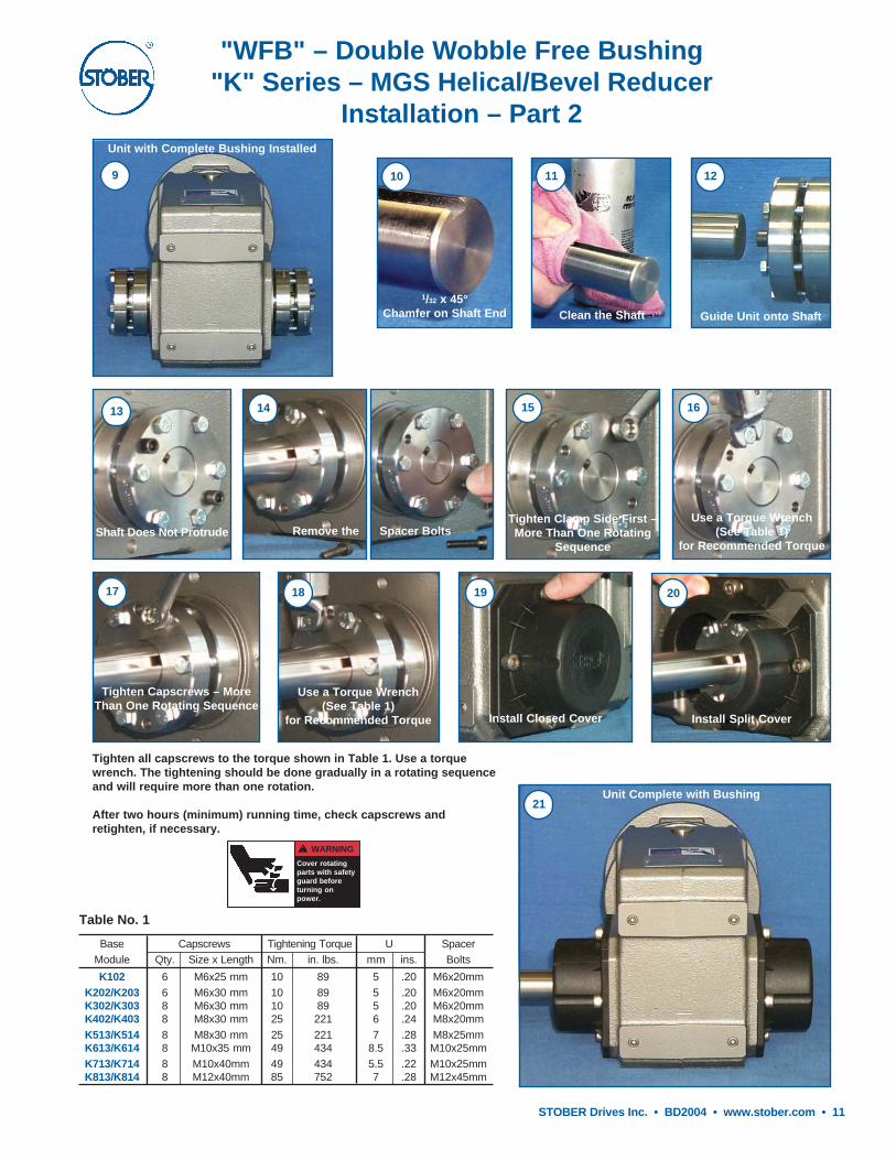
"WFB" – Double Wobble Free Bushing"K" Series – MGS Helical/Bevel Reducer
Installation – Part 2
Tighten Capscrews – MoreThan One Rotating Sequence
17
Use a Torque Wrench(See Table 1)
for Recommended Torque
18
Install Closed Cover
19
Install Split Cover
20
Guide Unit onto Shaft
12
Clean the Shaft
11
1/32 x 45°Chamfer on Shaft End
10
Unit with Complete Bushing Installed
9
Tighten all capscrews to the torque shown in Table 1. Use a torquewrench. The tightening should be done gradually in a rotating sequenceand will require more than one rotation.
After two hours (minimum) running time, check capscrews andretighten, if necessary.
Table No. 1
Base Capscrews Tightening Torque U SpacerModule Qty. Size x Length Nm. in. lbs. mm ins. Bolts
K102 6 M6x25 mm 10 89 5 .20 M6x20mmK202/K203 6 M6x30 mm 10 89 5 .20 M6x20mmK302/K303 8 M6x30 mm 10 89 5 .20 M6x20mmK402/K403 8 M8x30 mm 25 221 6 .24 M8x20mmK513/K514 8 M8x30 mm 25 221 7 .28 M8x25mmK613/K614 8 M10x35 mm 49 434 8.5 .33 M10x25mmK713/K714 8 M10x40mm 49 434 5.5 .22 M10x25mmK813/K814 8 M12x40mm 85 752 7 .28 M12x45mm
WARNING
Cover rotatingparts with safetyguard beforeturning onpower.
Unit Complete with Bushing21
Shaft Does Not Protrude
13
Remove the Spacer Bolts
14
Use a Torque Wrench(See Table 1)
for Recommended Torque
16
Tighten Clamp Side First –More Than One Rotating
Sequence
15

12 • STOBER Drives Inc. • BD2004 • www.stober.com
"WFB" – Double Wobble Free Bushing"K" Series – MGS Helical/Bevel Reducer
Mounting Information
Important: A 1/32 x 45° chamfer minimum is recommended for the shaft end.NOTE 1: The distance shown is the maximum allowable shaft exposure that will meet safety standards. To
disengage the bushing from the shaft with the back off bolts may require a distance of 11/4.
GL1/4" Max.See Note 1
L
BH
GA
DC Ref.
CLCover to Cover Length
Bore
G
P
OL
C
SUPPORTSIDE
CLAMPSIDE
FA
F
J
Table No. 1 Mounting Dimensions (Inches)Base Module BH C CL DC F FA G GA GL J L OL P
K102 .16 .24 7.80 3.07 3.54 1.18 2.76 1.38 2.28 M8 3.82 7.64 1.97K202/K203 .16 .39 9.36 3.46 4.53 1.38 3.54 1.77 2.52 M10 4.45 8.90 2.05K302/K303 .16 .43 9.95 3.78 5.12 1.57 4.13 2.07 2.47 M10 4.70 9.41 2.09K402/K403 .20 .47 11.60 4.33 6.10 1.97 4.72 2.36 2.97 M12 5.53 11.06 2.40K513/K514 .20 .43 12.09 4.54 5.51 1.57 4.92 2.46 3.15 M16 5.81 11.63 2.40K613/K614 .24 .51 13.22 5.00 6.30 1.97 5.12 2.56 3.54 M16 6.34 12.68 2.68K713/K714 .24 .39 15.36 5.75 7.09 2.17 5.71 2.85 4.12 M20 7.53 15.06 2.91K813/K814 .31 .64 18.68` 6.95 9.45 2.95 7.28 3.64 4.70 M24 9.01 18.02 3.43

STOBER Drives Inc. • BD2004 • www.stober.com • 13
The STOBER Difference . . . .. . . . Equals VALUE for you

14 • STOBER Drives Inc. • BD2004 • www.stober.com

STOBER Drives Inc. • BD2004 • www.stober.com • 15
Mounting PositionsOne Standard Unit for ALL Horizontal Mounting Positions Can be supplied on request.
Without Changing the Oil Level Be sure to specify when ordering.
EL1 EL2 EL3 EL4 EL5 EL6Possible
but not recommended.
Beverage Duty and Food Duty"C" Series – MGS Helical Concentric Reducers
NEMA C-face Input• O-ring between motor and
reducer• Easy mount maintenance
free coupling
Stainless Steel Output Shaft and Key
Double Sealed Output – with a dual lipouter seal and a single lip inner seal
• Lubricated for Life• Maintenance Free• Totally Enclosed (Watertight)• 3 Year Warranty – your guarantee of our confidence in the MGS (Modular Gear System) line of reducers• 97% Efficiency – for high quality and reliability plus cost savings in energy and maintenance
Stainless SteelNameplate
Indicates Beverage Duty.Indicates Food Duty.
ComparisonBEVERAGE DUTY FOOD DUTY
Coating: Industrial 316 Stainless Steel Epoxy Multilayer Industrial 316 Stainless Steel Epoxy
Shaft: Stainless Steel Stainless Steel
Key: Stainless Steel Stainless Steel
Seals: Double Double1- Dual Lip Outer Output Seal 1- Dual Lip Outer Output Seal1- Single Lip Inner Output Seal 1- Single Lip Inner Output Seal
Hardware: ALL Stainless Steel ALL Stainless Steel
Lubricant: Standard (Mobile 630) Standard (Mobile 630)
Options: Food Grade Oil (Exxon Univis Special Mist 220) Food Grade Oil (Exxon Univis Special Mist 220)Synthetic Oil (Mobil SHC630) Synthetic Oil (Mobil SHC630)
Ultra Clear Industrial Epoxy Ultra Clear Industrial EpoxyWhite Epoxy White Epoxy
Standard Coating – Industrial 316 Stainless Steel Epoxy– Multilayer Industrial 316 Stainless Steel Epoxy
Coating Options – Additional Layer Ultra Clear Industrial Epoxy– White Epoxy

16 • STOBER Drives Inc. • BD2004 • www.stober.com
Part No. ExampleBeverage Duty and Food Duty
Foot Mounting with Motor Adapter
C302N0620 MR160/140B
Drawing for UnitsC002N — C503N
P
J
UA
T
N
F
AB
G
S
R
H
U
Q
V
O
L
YC
EY
YBYA
M
UB
U
X
C
D
"C" Series–MGS Concentric/Helical ReducerDimensional Data
Table No. 3"C" Series – Foot Mounting Unit Dimensions (Inches) – "N" Housing Style
Motor Adapter NEMA C-Flange E X Y YA YB YC Wt. lbs.
MR140/050B 56C 5.51 3.31 6.50 4.500 5.87 .41 9
MR160/050B 56C 6.30 3.86 6.50 4.500 5.87 .41 16MR160/140B 143/145TC 6.30 3.86 6.50 4.500 5.87 .41 16
MR200/180B 182/184TC 7.87 4.80 9.00 8.500 7.25 .55 23
MR250/180B 182/184TC 9.84 5.31 9.00 8.500 7.25 .55 36MR250/210B 213/215TC 9.84 5.31 9.00 8.500 7.25 .55 36
MR300/180B 182/184TC 11.81 6.50 9.00 8.500 7.25 .57 75MR300/210B 213/215TC 11.81 6.50 9.00 8.500 7.25 .57 75MR300/250B 254/256TC 11.81 6.50 9.00 8.500 7.25 .57 75MR300/280B 284/286TC 11.81 6.50 11.13 10.500 9.00 .57 75
Table No. 2
Base Module S T U V Z1 UA – Key UB
C002 .43 3.62 .7500 1.57 — 3/16 × 3/16 × 17/32 .83
C102/C103 .51 4.88 1.0000 1.97 — 1/4 × 1/4 × 19/16 1.11C202/C203 .55 5.43 1.2500 2.36 — 1/4 × 1/4 × 115/16 1.36
C302/C303 .55 5.91 1.2500 2.36 — 1/4 × 1/4 × 115/16 1.36C402/C403 .75 6.89 1.6250 3.15 — 3/8 × 3/8 × 27/8 1.79
C502/C503 .87 7.56 1.6250 3.15 — 3/8 × 3/8 × 27/8 1.79C612/C613 .98 6.97 2.1250 3.94 6.57 1/2 × 1/2 × 35/32 2.35
Table No. 1 "C" Series – Foot Mounting Unit Dimensions (Inches) – "N" Housing Style
Base Module A B D F G H J M N O P Q R
C002 5.20 3.74 5.67 4.33 2.44 3.23 .28 1.38 .79 2.24 1.73 .16 2.17
C102/C103 6.93 4.65 6.97 5.91 2.76 4.02 .35 1.65 .98 2.72 2.13 .16 2.64C202/C203 7.87 5.31 7.68 6.69 3.35 4.53 .43 1.97 1.18 3.39 2.56 .16 3.11
C302/C303 8.46 6.06 8.46 7.28 4.13 5.121) .43 1.97 1.18 3.35 2.56 .16 3.11C402/C403 10.04 7.09 9.65 8.66 4.33 5.71 .55 2.36 1.38 4.17 3.39 .16 4.13
C502/C503 11.42 7.76 11.42 9.65 5.12 6.69 .71 2.76 1.57 4.21 3.39 .16 4.25C612/C613 11.81 10.43 12.40 9.65 8.46 7.87 .71 2.95 1.57 6.02 4.17 .20 5.12
1) "H" dimension on the input side of a C303 with an MR160/050 or MR160/140 is 3.66.

STOBER Drives Inc. • BD2004 • www.stober.com • 17
Drawing for UnitC612/C613N
UA
UB
J
H
E
C
Y
YB
YA
YC
Z1
LX
O
P
V
Q
S
G
B
U
T
D
N
M
A
FR
U
Units can be mounted in any horizontal output mounting positions.All weights are approximate.Units listed (C102 through C613) are the standard Beverage Duty and Food Duty sizes. For larger sizes not shown, consult STOBER Drives Inc.
"C" Series–MGS Concentric/Helical ReducerDimensional Data
Table No. 4 "C" Series – Foot Mounting Unit Dimensions (Inches) – "N" Housing Style
Base MR140/050B MR160/140B 2) MR200/180B MR250/210B 3) MR300/250B 4) Approx.
Module C L C L C L C L C L Wt.(lbs.)
C002 9.37 6.06 10.08 6.22 — — — — — — 18
C102 10.67 7.36 11.38 7.52 12.40 7.60 — — — — 29C103 12.13 8.82 — — — — — — — — 34C202 11.77 8.46 12.48 8.62 13.50 8.70 — — — — 38C203 13.23 9.92 14.17 10.31 — — — — — — 45
C302 — — 13.23 9.37 14.25 9.45 14.88 9.57 — — 49C303 13.98 10.67 14.92 11.06 — — — — — — 56C402 — — 15.12 11.26 16.14 11.34 16.77 11.46 — — 71C403 — — 16.81 12.95 — — — — — — 78
C502 — — 15.95 12.09 16.97 12.17 17.59 12.28 19.33 12.83 95C503 — — 17.64 13.78 — — — — — — 111C612 — — — — 17.91 13.11 18.54 13.23 20.24 13.74 115C613 — — 18.62 14.76 20.35 15.55 — — — — 159
2) Also available as MR160/050B for a NEMA 56C frame motor. "H" dimension on the input side of a C303 with an MR160/050 or MR160/140 is 3.66.3) Also available as MR250/180B for a NEMA 182/184TC frame motor.4) Also available as MR300/180B for a NEMA 182/184TC, MR300/210B for a NEMA 213/215TC , and MR300/280B for a NEMA 284/286TC frame motor.
Housing Style Options–See the MGS catalog.N – Foot Mounted F – Round Flange G – Tapped Holes
Part No. ExplanationC 3 0 2 N 0620 MR 160 / 140 B
Beverage DutyMotor Frame Size
Flange No.Motor Adapter
Ratio (0620 = 61.92:1)"N" Housing Style (also "F", "G", "Q")
No. of Gear ReductionsGeneration No.
Unit No.Concentric Helical

18 • STOBER Drives Inc. • BD2004 • www.stober.com
Poultry Duty"F" Series – MGS Offset Helical Reducer
• Lubricated for Life• Maintenance Free• Totally Enclosed (No Vent Required)• 3 Year Warranty – your guarantee of our confidence in the MGS (Modular Gear System) line of reducers• 97% Efficiency – for high quality and reliability plus cost savings in energy and maintenance
Mounting PositionsOne Standard Unit for ALL Horizontal Mounting Positions
Without Changing the Oil Level
EL1 EL2 EL3 EL4
Stainless Steel Nameplate
NEMA C-face Input –O-ring between motor andreducer with an easy mount,maintenance free coupling
Outside Cover Cap – protects sealsfrom high pressure washing
Double Sealed Output – with adual lip outer seal and a singlelip inner seal
Stainless Steel Output Quill
Standard Coating – Industrial 316 Stainless Steel Epoxy

STOBER Drives Inc. • BD2004 • www.stober.com • 19
Hollow Output"F" Series – MGS Offset Helical Reducer
Dimensional Data
1. Removal Bolt — not supplied.2. Mounting Bolt — must be smaller than removal bolt.All weights are approximate.
Part No. ExamplePoultry Duty Unit with Motor Adapter
F302AG0560 MR160/140B
E
UA
G
Drawing for UnitsF202AG — F303AG
UL
UC M
L
UB
U
T
H
D
F
BP
B
21
B
J *
I
Y
H1
CD
YB
YA
YC
X
C
V
P
Table No. 1 "F" Series – Unit Dimensions (Inches) – "G" Housing Style
Base Module CD B D F G H H1 I J * M P T U V BC BP UA UB UC UL 1
F202/F203 5.16 4.53 11.77 4.53 .87 3.66 8.82 .51 M8 3.740 .12 7.09 1.0000 .31 4.76 4.13 .250 1.12 1.77 3.62 1/2-13F302/F303 5.89 5.12 13.23 5.12 1.18 4.17 10.06 .63 M10 4.331 .14 8.11 1.2500 .33 5.45 4.72 .250 1.37 1.97 4.06 1/2-13
Table No. 2"F" Series — Unit Dimensions (Inches) – "G" Housing Style
Motor Adapter NEMA C-Flange E X Y YA YB YC Wt. lbs.
MR140/050B 56C 5.51 3.31 6.50 4.500 5.87 .41 9
MR160/050B 56C 6.30 3.86 6.50 4.500 5.87 .41 16MR160/140B 143/145TC 6.30 3.86 6.50 4.500 5.87 .41 16
MR200/180B 182/184TC 7.87 4.80 9.00 8.500 7.25 .55 23
Table No. 3"F" Series Unit Dimensions (Inches)
Base MR140/050B MR160/140B 1) MR200/180B Approx.Module C L C L C L Wt. lbs.
F202 8.15 4.84 8.86 5.00 9.88 5.08 51F203 9.61 6.30 — — — — 64F302 8.74 5.43 9.45 5.59 10.47 5.67 67F303 10.20 6.89 — — — — 73
1) Also available as MR160/050B for a NEMA 56C frame motor.
BC(to cover)
See the MGS catalog for other housing styles not shown here.
Part No. ExplanationF 3 0 2 A G 0560 MR160/140B
143/145TC Motor AdapterRatio (0560 = 56.49:1)
"G" Housing Style"A" Hollow Output Bore
No. of Gear ReductionsGeneration No.
Unit No.OFfset Helical

20 • STOBER Drives Inc. • BD2004 • www.stober.com
Poultry Duty"K" Series – MGS Helical/Bevel Reducers
Stainless Steel Nameplate
NEMA C-face Input –O-ring between motor and reducerEasy mount, maintenance freecoupling
Outside Cover Cap – protects sealsfrom high pressure washing
• Lubricated for Life• Maintenance Free• Totally Enclosed (No Vent Required)• 3 Year Warranty – your guarantee of our confidence in the MGS (Modular Gear System) line of reducers• 97% Efficiency – for high quality and reliability plus cost savings in energy and maintenance
Double Sealed Output – witha dual lip outer seal and asingle lip inner seal
Stainless Steel Output Quill
Mounting PositionsOne Standard Unit for ALL Horizontal Mounting Positions
Without Changing the Oil Level
EL1 EL2 EL5 EL6Possible but not recommended
Standard Coating – Industrial 316Stainless Steel Epoxy

STOBER Drives Inc. • BD2004 • www.stober.com • 21
Hollow Output"K" Series – MGS Helical/Bevel Reducer
Dimensional Data
1. Removal Bolt — not supplied.2. Mounting Bolt — must be smaller than removal bolt.All weights are approximate.
J
I
E
C
SUB
(UB2)
UA(UA2)
Drawing for UnitsK202AG — K403AG
2
P
Y
YB
YA
YC
A
CD
X T
1
U(U2)
GA
BP
B
R
G
H
D
M
UL
B
F
UC
Part No. ExampleTapped Holes Housing with Motor Adapter
K303AG0650 MR160/140B
Table No. 1 "K" Series – Unit Dimensions (Inches) – "G" Housing Style
Base Module A B D F G H I J M P R S U U2
K102 4.13 4.41 6.30 3.54 2.76 1) 2.36 .51 1) M8 1) 2.953 .12 3.54 2.36 1.000 –K202/203 4.57 5.83 7.48 3.94 3.54 2.56 .51 M8 3.228 .12 4.53 2.56 1.250 –K302/303 5.20 6.30 8.39 4.53 4.13 2.95 .51 M8 3.740 .12 5.12 2.95 1.250 1.375
1) K102 units have mounting holes on Side 1 (top) and Side 2 (bottom).
Table No. 3 "K" Series – Unit Dimensions (Inches)
Base MR140/050B MR160/140B 2) MR200/180B Wt.
Module CD C T CD C T CD C T lbs.
K202 1.81 11.50 5.63 1.81 12.21 5.79 1.81 13.23 5.87 40K203 1.81 12.96 7.09 — — — — — — 53K302 2.07 12.68 6.42 2.07 13.38 6.57 2.07 14.40 6.65 67K303 2.07 14.13 7.87 .63 15.08 8.27 — — — 73
2) Also available as MR160/050B for a NEMA 56C frame motor.
Table No. 4 Motor Adapter Dimensions (Inches)
Motor Adapter NEMA C-Flange E X Y YA YB YC Wt. lbs.
MR140/050B 56C 5.51 3.31 6.50 4.500 5.87 .41 9
MR160/050B 56C 6.30 3.86 6.50 4.500 5.87 .41 16MR160/140B 143/145TC 6.30 3.86 6.50 4.500 5.87 .41 16
MR200/180B 182/184TC 7.87 4.80 9.00 8.500 7.25 .55 23
BC
See the MGS catalog for other housing styles not shown here.
Table No. 2Base Module BC BP GA UA UA2 UB UB2 UC UL 1
K102 4.85 4.17 1.38 1) .250 – 1.11 – 1.57 3.86 1/2-13K202/203 6.15 5.28 1.77 .250 – 1.31 – 1.77 4.78 1/2-13K302/303 6.62 5.75 2.07 .250 .312 1.38 1.52 1.97 4.92 5/8-11
Part No. ExplanationK 3 0 3 A G 0650 MR160/140B
143/145TC Motor AdapterRatio (0650 = 65.5:1)
"G" Housing Style"A" Hollow Output Bore
No. of Gear ReductionsGeneration No.
Unit No.Right Angle Helical/Bevel

22 • STOBER Drives Inc. • BD2004 • www.stober.com
Motor Mounting InstructionsMGS Speed Reducers
Step 2.
Locate the Motor Coupling on the Motor Shaft
Mount the coupling with the hub projection toward the step or shoulder ofthe motor. The motor shaft should project through the coupling by the "X"dimension (or the value determined using the previous measurement).
Table No. 2 Location of Motor CouplingAdapter "X" "X" Adapter "X" "X"Part No. mm inches Part No. mm inches
MR140/050B 28 1.1 MR250/180B 30 1.2MR160/050B 22 .9 MR250/210B 46 1.8MR160/140B 25 1.0 MR300/180B 10 .4MR200/050B 12 .5 MR300/210B 26 1.0MR200/140B 12 .5 MR300/250B 42 1.7MR200/180B 30 1.2 MR300/280B 58 2.3
"X" Tolerance is +1mm / -0mm (+0.040 / -0.000 inches)
Step 3.Tighten the Setscrew
With the coupling hub located at the correct distance, tighten the setscrewin the coupling.
56C - 145TC 182TC - 365TC
Step 1.
Measure the Motor Shaft
Accurate measurement of the motor shaft is vital to mounting the motorcoupling correctly. The measurement must be taken from the face of themotor or pilot surface (see above) to the end of the motor shaft. If thisdimension is the same as the NEMA standard "AH" dimension shown inTable No. 1, proceed with the motor mounting in Step 2.
Table No. 1 NEMA Motor Shaft DimensionsMotor "AH" Shaft Motor "AH" ShaftFrame Dia. Frame Dia.
56C 21/16 5/8 254/256TC 33/4 15/8
143/145TC 21/8 7/8 284/286TC 43/8 17/8
182/184TC 25/8 11/8 324/326TC 5 21/8
213/215TC 31/8 13/8 364/365TC 55/8 23/8
If the motor shaft length measurement is less than "AH", subtract thedifference ( 1) from the "X" dimension shown in Table No. 2.If the motor shaft length measurement is greater than "AH", add thedifference ( 2) to the "X" dimension shown in Table No. 2.
AH56C - 145TC
1
X
X- 1
X+ 2
AH182TC - 365TC
2

STOBER Drives Inc. • BD2004 • www.stober.com • 23
Motor Mounting InstructionsMGS Speed Reducers
Step 4.Secure the Motor Shaft Key
For ease of installation, secure the motor shaft key. Staking near the endof the keyway, on the sides of the key, or a temporary adhesive workswell.
Step 5.Mount the Motor
With the coupling secure, insert the motor shaft into the motor adapter.The coupling sleeve is already installed on the mating reducer couplinghub inside the motor adapter. The sleeve should move freely in an axialdirection. (Axial displacement ±.040 inches.)With the motor in place, tighten the motor bolts.
CAUTION:IF THE MOTOR COUPLING IS NOT INSTALLED CORRECTLY, THEINPUT BEARING MAY FAIL DUE TO PRE-LOAD. THIS WILL VOID THEWARRANTY OF THE REDUCER AND POSSIBLY FAIL THE MOTOR.
Some motor manufacturers provide a drain hole in the mounting face ofwashdown motors. In some mounting positions, water or other materialcan enter the motor adapter and fail the bearing.Be sure this hole is covered during washing or when the unit is in a wetenvironment. The illustration shows the method that STOBER assemblypersonnel uses to plug the hole.
Sleeve Motor CouplingHub
Table No. 1Couplings Used with MR Motor AdaptersAdapter NEMA Frame Motor Hub Sleeve
MR140/050B 56C M-19 x 5/8 M-19
MR160/050B 56C M-24 x 5/8 M-24MR160/140B 143/145TC M-24 x 7/8 M-24
MR200/050B 56C M-32 x 5/8 M-32MR200/140B 143/145TC M-32 x 7/8 M-32MR200/180B 182/184TC M-32 x 11/8 M-32
MR250/180B 182/184TC M-38 x 11/8 M-38MR250/210B 213/215TC M-38 x 13/8 M-38
MR300/180B 182/184TC M-48 x 11/8 M-48MR300/210B 213/215TC M-48 x 13/8 M-48MR300/250B 254/256TC M-48 x 15/8 M-48MR300/280B 284/286TC M-48 x 17/8 M-48
Shown in Table No. 1 is the motor coupling hub and sleeve part numberfor the STOBER MGS® motor adapter. These parts, with a coupling shaftcomponent that is part of the reducer, make a complete coupling toconnect the motor to the reducer.

24 • STOBER Drives Inc. • BD2004 • www.stober.com
1. GENERAL. All orders for products supplied bySTOBER DRIVES INC. (“Stober”) shall be subject tothese terms and conditions of sales. All transactionsshall be governed by the laws of the Commonwealth ofKentucky. No modifications hereto will be binding unlessagreed to in writing by Stober.
2. CUSTOMER. The term “Customer,” as usedherein, means the distributor, resale dealer, originalequipment manufacturer or first end-user customerthat purchases the Stober products.
3. WARRANTY. Stober products shall be free fromdefects in material and workmanship for a maximum of5-years (single shift operation or 30 months multipleshift operation) for ServoFit products; 3-years (singleshift operation or 18 months multiple shift operation) forMGS products; 2-years (single shift operation or 12months multiple shift operation) for TD products, fromthe date of shipment to the Customer. For ServoFitproducts, all normal wear items, including oil seals andbearings, shall be covered for a period of 2-years(single shift operation or 12 months multiple shiftoperation). In the event that a product proves to bedefective, Stober’s sole obligation shall be, at itsoption, to repair or replace the product. The repairedor replacement product will be shipped F.O.B. Stober’sfacilities, freight prepaid by Stober.
No employee, agent or representative of Stober hasthe authority to waive, alter, vary or add to the termshereof without the prior written approval of an officer ofStober. It is expressly agreed that (a) this sectionconstitutes the final expression of the parties’understanding with respect to the warranty and (b) thissection is a complete and exclusive statement of theterms of the warranty.
Stober shall have no obligation under the warranty setforth above in the event that:
(a) The Customer fails, within the warranty period tonotify Stober in writing and provide Stober withevidence satisfactory to Stober of the allegeddefect within five (5) days after it becomes knownto the customer;
(b) After inspection of a product, Stober determines,in its sole discretion, that it is not defective inmaterial or workmanship;
(c) Repair or replacement of a product is requiredthrough normal wear and tear;
(d) Any part in a product or any ingredient containedin a product requires replacement or repair throughroutine usage or normal wear and tear;
(e) A product is not maintained or used in accordancewith Stober’s applicable operating and/ormaintenance manuals, whether by the Customeror any third party;
(f) A product has been subject to misuse,misapplication, negligence, neglect (including, butnot limited to, improper maintenance or storage),accident, catastrophe, improper installation,modification, adjustment, repair or lubrication,whether by the Customer or any third party, withoutthe prior written consent of Stober. Misuse shallinclude, but not be limited to, deterioration in aproduct due to chemical action and wear causedby the presence of abrasive materials;
(g) The system of connected rotating parts into whichthe product becomes incorporated is notcompatible with the product, or it is not free fromcritical speed or torsional or other type of vibrationwithin the specified operating range, no matterhow induced; or
(h) The transmitted load and imposed torsional thrustand overhung loads are not within the publishedcapacity limits for the unit sold.
Items manufactured by other parties but installed in oraffixed to Stober’s products are not warranted byStober and bear only those warranties, express orimplied, which are given by the manufacturer of suchitems, if any.
THE WARRANTY SET FORTH ABOVE IS INTENDEDSOLELY FOR THE BENEFIT OF THE Customer ANDDOES NOT APPLY TO ANY THIRD PARTY. ALLCLAIMS MUST BE MADE BY THE Customer ANDMAY NOT BE MADE BY ANY THIRD PARTY. THISWARRANTY MAY NOT BE TRANSFERRED ORASSIGNED, IN WHOLE OR IN PART, BY THECustomer FOR ANY REASON WHATSOEVER. ANYSUCH ATTEMPTED TRANSFER OR ASSIGNMENTSHALL BE NULL AND VOID.
THIS WARRANTY TAKES THE PLACE OF ALLOTHER WARRANTIES, EXPRESS OR IMPLIED,WHICH ARE HEREBY DISCLAIMED ANDEXCLUDED BY STOBER, INCLUDING WITHOUTLIMITATION, ANY WARRANTY OFMERCHANTABILITY OR FITNESS FOR APARTICULAR PURPOSE OF USE AND ALLOBLIGATIONS OR LIABILITIES ON THE PART OFSTOBER FOR DAMAGES ARISING OUT OF OR INCONNECTION WITH THE USE, REPAIR ORPERFORMANCE OF THE PRODUCTS.
4. MODIFICATIONS. Stober reserves the right,without notice to the Customer, to (a) change thespecifications of any product, (b) improve a product inany manner that Stober deems necessary or appropriateand (c) discontinue the manufacture of any product.
5. PURCHASE ORDERS. The Customer will submitpurchase orders for the products to Stober in writing,whether by mail or telefax, which shall set forth, at aminimum: (a) an identification of the products ordered,(b) prices for such products, (c) quantities, (d) requesteddelivery dates and (e) shipping instructions and shippingaddresses.
6. ACCEPTANCE OF ORDERS. All purchase ordersreceived from the Customer are subject to acceptanceby Stober in writing.
7. MODIFICATION OF ORDERS. No acceptedpurchase order shall be modified or canceled exceptupon the written agreement of Stober and the Customer.Mutually agreed cancellations shall be subject toreasonable charges based upon expenses alreadyincurred by Stober and commitments made by Stober.Mutually agreed change orders shall be subject to allprovisions of these Terms and Conditions of Sale.
8. PRICE INCREASES. Stober may increase itsprices for the products by providing the originalpurchaser of the products with at least thirty (30) days’prior written notice. Increased prices for products shallnot apply to purchase orders accepted prior to theeffective date of the price increase unless such ordersprovide for delivery more than thirty (30) days after thedate of acceptance of the order.
9. PRICING AND DELIVERY TERMS. Inaccordance with KRS 355.2-319(1)(b), all products aredelivered F.O.B. Stober's warehouse facility in Maysville,Kentucky, or such other facility as Stober may designate.Orders are then shipped per Customer's shippinginstructions as set forth in Customer's purchase order.CATALOG PRICING DOES NOT INCLUDESHIPPING, HANDLING AND TAXES. Once deliveredto a common carrier of the Customer's choosing [or ofStober's choosing if Customer has failed to specify acommon carrier on or before five (5) days prior to therequested delivery date] Stober shall have no furtherresponsibility for the products and all risk of damage,loss or delay shall pass to the Customer. A handling feeis added to freight costs by Stober to cover the cost ofhaving to pay the carrier within seven (7) days when theterms with the Customer are net 30. The Customer hasthe option of shipping collect with our carrier or thecarrier of choice.
10. PAYMENT TERMS. Net 30 days. All orders willbe shipped either prepaid by the Customer or C.O.D.,at Stober’s option, unless the Customer has establisheda previously approved credit line. If Stober approves acredit line for the Customer, all payments shall be duewithin thirty (30) days of the date of the invoice. If anyinvoice is not paid in full within such thirty (30) dayperiod, then finance charges shall be assessed at the
rate of one and one-half percent (11/2%) per month(eighteen percent (18%) per year). If such rate isdeemed to be usurious at any time, it shall be reducedto the maximum rate permitted by applicable law.Stober may stop or withhold shipment of products if theCustomer does not fulfill its payment obligations. IfStober is insecure about payment for any reason,Stober may require full or partial payment in advanceand as a condition to the continuation of its delivery ofproducts.
11. SECURITY INTEREST. Unless and until theproducts are paid for in full, Stober reserves a securityinterest in them to secure the unpaid balance of thepurchase price. The Customer hereby grants to Stobera power of attorney, coupled with an interest, to executeand file on behalf of the Customer all necessary financingstatements and other documents required orappropriate to protect the security interest grantedherein.
12. ACCEPTANCE OF PRODUCTS. The Customerwill conduct any incoming inspection tests as soon aspossible upon arrival of the products, but in no eventlater than ten (10) days after the date of receipt. Anyproducts not rejected by written notice to Stober withinsuch period shall be deemed accepted by the Customer.Stober shall not be liable for any additional costs,expenses or damages incurred by the Customer, directlyor indirectly, as a result of any shortage, damage ordiscrepancy in a shipment.
13. LIMITATION OF REMEDIES.(a) STOBER SHALL NOT BE LIABLE FOR ANY
LOSS OR DAMAGE CAUSED BY DELAY INFURNISHING THE CUSTOMER WITHPRODUCTS.
(b) IN NO EVENT SHALL STOBER’S LIABILITYINCLUDE ANY SPECIAL, INDIRECT,INCIDENTAL OR CONSEQUENTIALLOSSES OR DAMAGES, EVEN IF STOBERHAS BEEN ADVISED OF THE POSSIBILITYOF SUCH POTENTIAL LOSS OR DAMAGE.
14. MADE-TO-ORDER PRODUCTS. Stober reservesthe right to revoke and amend any price quotationsoffered to the Customer for made-to-order products,provided that such price quotations have not beenaccepted by the Customer prior to the date of revocationor amendment.
15. DIES, TOOLS AND EQUIPMENT. Chargesincurred by the Customer for dies, tools and otherequipment shall not confer ownership or the right topossession therein by the Customer. All such dies,tools and equipment shall remain the property of Stober,and Stober shall have the exclusive right to possessionthereof. Stober shall maintain such tools and equipmentin good working order.
16. REGULATORY LAWS AND STANDARDS.Stober makes no representation that its productsconform to state or local laws, ordinances, regulations,codes or standards except as may be otherwise agreedto in writing by Stober.
17. SIZES AND WEIGHTS. Stober’s products aremade only in the sizes and to the specifications set forthin its catalogs and other literature. If any alteration isrequested, such altered product will be treated as amade-to-order item. Stober assumes no responsibilityfor typographical errors which may appear in its catalogsor literature, and cannot accept alteration chargescaused by such errors. Since weights shown in Stober’scatalogs are approximate, they cannot be used indetermining freight allowances set forth in its catalogsand other literature. Freight allowances will bedetermined at the time of shipment and shall be basedon actual shipping weight.
18. SYSTEM DESIGN. Responsibility for systemdesign to ensure proper use and application of Stober’sproducts within their published specifications and ratingsrests solely with the Customer. This includes, but is notlimited to, an analysis of loads created by torsionalvibrations within the entire system, regardless of howinduced.
Terms and Conditions of Sale