beyond organometallic flow chemistry : the principles behind the … · 1 beyond organometallic...
TRANSCRIPT

Beyond organometallic flow chemistry : the principles behindthe use of continuous-flow reactors for synthesisCitation for published version (APA):Noel, T., Su, Y., & Hessel, V. (2015). Beyond organometallic flow chemistry : the principles behind the use ofcontinuous-flow reactors for synthesis. In T. Noël (Ed.), Organometallic Flow Chemistry (pp. 1-42). (Topics inOrganometallic Chemistry; Vol. 57). Berlin: Springer. https://doi.org/10.1007/3418_2015_152
DOI:10.1007/3418_2015_152
Document status and date:Published: 10/10/2015
Document Version:Accepted manuscript including changes made at the peer-review stage
Please check the document version of this publication:
• A submitted manuscript is the version of the article upon submission and before peer-review. There can beimportant differences between the submitted version and the official published version of record. Peopleinterested in the research are advised to contact the author for the final version of the publication, or visit theDOI to the publisher's website.• The final author version and the galley proof are versions of the publication after peer review.• The final published version features the final layout of the paper including the volume, issue and pagenumbers.Link to publication
General rightsCopyright and moral rights for the publications made accessible in the public portal are retained by the authors and/or other copyright ownersand it is a condition of accessing publications that users recognise and abide by the legal requirements associated with these rights.
• Users may download and print one copy of any publication from the public portal for the purpose of private study or research. • You may not further distribute the material or use it for any profit-making activity or commercial gain • You may freely distribute the URL identifying the publication in the public portal.
If the publication is distributed under the terms of Article 25fa of the Dutch Copyright Act, indicated by the “Taverne” license above, pleasefollow below link for the End User Agreement:www.tue.nl/taverne
Take down policyIf you believe that this document breaches copyright please contact us at:[email protected] details and we will investigate your claim.
Download date: 26. May. 2020

1
Beyond organometallic flow chemistry:
The principles behind the use of continuous-flow
reactors for synthesis
Timothy Noël,a,b* Yuanhai Sua and Volker Hessela
a Eindhoven University of Technology, Micro Flow Chemistry & Process Technology,
Building 14, Helix, room STW 1.48, De Rondom 70, 5612 AP Eindhoven, The Netherlands.
b Department of Organic Chemistry, Ghent University, Krijgslaan 281 (S4), 9000 Gent,
Belgium
e-mail: [email protected]
Abstract
Flow chemistry is typically used to enable challenging reactions which are difficult to carry
out in conventional batch equipment. Consequently, the use of continuous-flow reactors for
applications in organometallic and organic chemistry has witnessed a spectacular increase in
interest from the chemistry community in the last decade. However, flow chemistry is more
than just pumping reagents through a capillary and the engineering behind the observed
phenomena can help to exploit the technology’s full potential. Here, we give an overview of
the most important engineering aspects associated with flow chemistry. This includes a
discussion of mass-, heat-, and photon-transport phenomena which are relevant to carry out
chemical reactions in a microreactor. Next, determination of intrinsic kinetics, automation of
chemical processes, solids handling and multistep reaction sequences in flow are discussed.
Safety is one of the main drivers to implement continuous-flow microreactor technology in
an existing process and a brief overview is given here as well. Finally, the scale-up potential
of microreactor technology is reviewed.
Keywords
flow chemistry – microreactors – continuous flow – continuous manufacturing - synthesis
Contents
1. Introduction
2. Continuous manufacturing in the pharmaceutical industry

2
3. Mass transport phenomena
4. Heat transport phenomena
5. Photon transport phenomena
6. Determination of intrinsic kinetics and automation of chemical processes
7. Safety aspects
8. Solids handling in flow
9. Multistep synthesis
10. Scalability
11. Conclusion
1. Introduction
Continuous-flow reactors have been increasingly used in synthetic organic chemistry to
facilitate chemistries which are otherwise difficult to carry out. This includes gas-liquid
reactions, photochemical transformations, chemistries utilizing hazardous compounds,
extreme reaction conditions and multistep reaction sequences. While many chemists
understand the chemistry behind flow chemistry really well, the engineering aspects of the
field are less understood. This seems initially not to be a major hurdle, but a thorough
understanding of the engineering principles behind the observations would allow one to get
the maximum out of the technology. In this chapter, we give an overview of the most
important engineering aspects, which are relevant for continuous-flow chemistry in
microreactors. The deeper meaning of these principles is further explained by giving relevant
examples. It is our hope that this overview will aid the reader to recognize where continuous-
flow reactors might actually make a difference for their chemistry and to exploit its full
potential.
2. Continuous manufacturing in the pharmaceutical industry
The use of continuous manufacturing is very common in the petrochemical industry, whereas
in the pharmaceutical industry, the most used manufacturing principle remains batch
processing. However, in recent years, continuous manufacturing has been recognized as one
of the key green engineering research areas by the ACS GCI Pharmaceutical Roundtable.1
Researchers from Eli Lilly and Company compared the use of a batch and flow process for a
high pressure asymmetric hydrogenation.2 For this process, a high hydrogen pressure of 70
bar is required to provide high TON and TOF of the expensive catalyst. They concluded that
a flow protocol was the best compromise as it provided a more practical, safe, faste and
flexible alternative for traditional batch manufacturing. Due to the high attrition rate in the
pharmaceutical industry, the capital cost is a major driver. The flow plant would cost about
10 times less and was more flexible with regard to production rate. Furthermore, the
development of a large scale high pressure autoclave (1000 L) would be time consuming for
the process engineers. The batch protocol was considered as a high risk operation due to the
use of hydrogen at elevated pressure, while the corresponding hydrogenation in flow was

3
categorized as a much lower risk because of the small liquid and gas holdup and the reduction
of the upper explosion limit. This example shows that there is indeed a need for continuous
manufacturing in the pharmaceutical industry and several drivers for its implementation have
been identified and categorized in three main groups: logistics/quality, chemistry/process, and
safety (Table 1).2, 3 One of the main reasons why the pharmaceutical industry has not changed
its entire production processes to continuous flow is the requirement of special equipment
(investment cost). In addition, specialized equipment is of high risk as the company has
typically only a few people who are familiar with continuous manufacturing and who can
trouble shoot in case of failure.4 However, most companies have established small
continuous-flow research groups as they recognize the importance of the technology.5 As
such, continuous-flow processing will slowly but definitely gain ground, eventually
displacing established batch techniques. This is also called “disruptive innovation”, a term
coined by Cristensen.6
Table 1. Main drivers for the implementation of continuous-flow processing in the
pharmaceutical industry.2
Logistics/Quality Chemistry/Process Safety
Higher throughput
Speed of implementation
Minimization of stock
inventory
Extreme reaction
conditions (high p, T)
Unstable intermediates
Demanding separations
Exothermic reactions
Reaction at high pressure
with hazardous gases
No vapor head space
Toxic reagents or
products
Researchers from the MIT-Novartis Center for Continuous Manufacturing demonstrated that
it is indeed feasible to prepare complex active pharmaceutical ingredients in a continuous-
flow process.7 A fully operational pilot plant was developed for the preparation of Aliskiren
and integrated all required processes including synthesis, purification, formulation and
tableting. The process could be operated for 10 days, which included startup and the
stabilization of key processes, and produced 45g/h of Aliskiren. Interestingly, the number of
unit operations could be largely reduced from 21 in batch to 14 in flow. The total processing
time could be reduced from 300 hours in batch to 47 hours in flow. However, it must be
noted that the reaction was reengineered to avoid solids handling and solvent swaps.
The change to continuous-flow processing fits also with the current trends in Process
Intensification.8, 9 The aim of Process Intensification is to have a drastic improvement of the
equipment performance and process efficiency. One of the most popular Process
Intensification technologies are microreactors, as it allows to intensify heat transport, mass
transport and photon transport phenomena.10 This mainly arises from the large surface-to-
volume ratios in microreactors.11 In addition, the chemistry can be further accelerated by
using extreme reaction conditions, such as elevated reaction temperatures and pressures. This
concept of using unusual reaction conditions is also called Novel Process Windows, coined
by Hessel.12-14 The use of microreactor technology further provides enhanced process safety,
high control over the reaction conditions, and increasing throughput by controlled scalability.
According to a detailed investigation of Roberge et al., 50% of the reactions in the

4
pharmaceutical and fine chemical industry could benefit from a continuous process.15 For
most of these reactions, the use of a microreactor would be actually the preferred device.
However, solid forming reactions were categorized as unsuitable for microreactor
technology, thus reducing the total amount of suitable reactions significantly. In recent years,
a lot of progress has been made to overcome the hurdles of microreactor clogging.16
3. Mass transport phenomena
The overall performance of a reaction is determined by the intrinsic kinetics of the reaction
and the transport properties in the reactor. The reaction rate and selectivity are substantially
influenced by the mass transfer rate. A fundamental understanding of the reaction kinetics
and the mass transfer characteristics is required to design a suitable reactor and scale up the
chemistry from laboratory to full production scale.
The degree of mixing influences the outcome of the reaction. The mixing efficiency is
directly related to the flow regime, which is characterized by the Reynolds number (Re):
Re hD u
(1)
where ρ is the fluid density, u the fluid velocity, Dh the hydraulic diameter of the channel and
µ the dynamic viscosity. The Reynolds number describes the ratio between the intertial and
viscous forces. At high Re (Re > 2500), the flow regime is turbulent and fluid elements
exhibit a random motion, which facilitates convective mass transport. At low Re (Re <<
1500), a laminar flow regime is observed. Hereby, the fluid elements flow in parallel lamellae
and mixing is governed by molecular diffusion only.
At macroscale, mixing is typically achieved by inducing a turbulent flow regime. However,
owing to the small length scales, often only a laminar flow profile is observed in
microchannels (Re < 100).17-19 This means that mixing is achieved by diffusion of molecules
from one lamella to a neighboring one. The characteristic mixing time (tm) can be calculated
by the Einstein-Smoluchovski equation:
2
m
Lt
D (2)
where L is the diffusion distance and D is the molecular diffusivity. From this equation, it is
evident that smaller dimensions lead to faster mixing. This insight has led to the development
of micromixers in which the diffusion distance is reduced by splitting two reaction streams in
several lamellae which are subsequently recombined (e.g. interdigital micromixer) (Figure 1).
Such passive micromixers utilize flow energy (originates from the pump) to facilitate
micromixing. Other passive micromixers are for example T- and Y-shaped micromixers,
split-and-recombine micromixers, packed-bed microchannels, caterpillar micromixers.20 Such
a mixing process is called chaotic advection, in which fluid elements are mixed by a net
transport of matter.21 Chaotic advection is much more efficient then molecular diffusion and
can be used to speed up the mixing efficiency. Active micromixers utilize external energy to
introduce flow perturbations and thus to facilitate mixing. Suitable energy sources for active
5
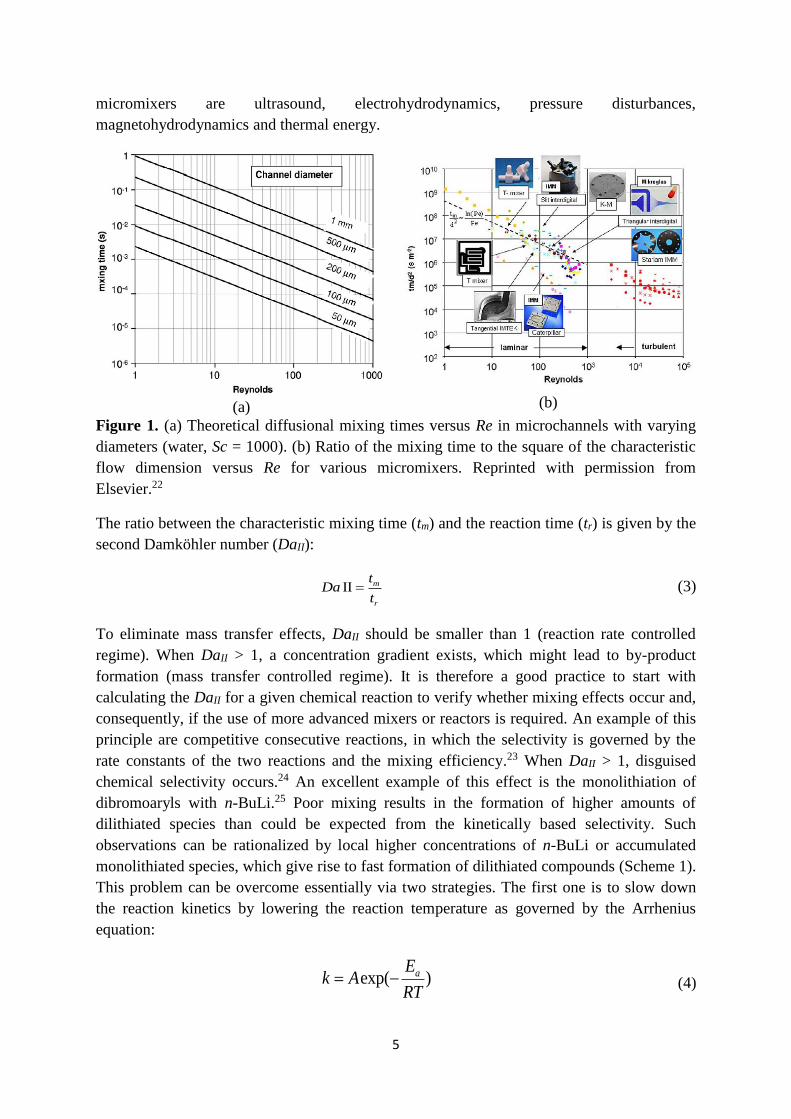
micromixers are ultrasound, electrohydrodynamics, pressure disturbances,
magnetohydrodynamics and thermal energy.
(a)
(b)
Figure 1. (a) Theoretical diffusional mixing times versus Re in microchannels with varying
diameters (water, Sc = 1000). (b) Ratio of the mixing time to the square of the characteristic
flow dimension versus Re for various micromixers. Reprinted with permission from
Elsevier.22
The ratio between the characteristic mixing time (tm) and the reaction time (tr) is given by the
second Damköhler number (DaII):
ІІ m
r
tDa
t (3)
To eliminate mass transfer effects, DaII should be smaller than 1 (reaction rate controlled
regime). When DaII > 1, a concentration gradient exists, which might lead to by-product
formation (mass transfer controlled regime). It is therefore a good practice to start with
calculating the DaII for a given chemical reaction to verify whether mixing effects occur and,
consequently, if the use of more advanced mixers or reactors is required. An example of this
principle are competitive consecutive reactions, in which the selectivity is governed by the
rate constants of the two reactions and the mixing efficiency.23 When DaII > 1, disguised
chemical selectivity occurs.24 An excellent example of this effect is the monolithiation of
dibromoaryls with n-BuLi.25 Poor mixing results in the formation of higher amounts of
dilithiated species than could be expected from the kinetically based selectivity. Such
observations can be rationalized by local higher concentrations of n-BuLi or accumulated
monolithiated species, which give rise to fast formation of dilithiated compounds (Scheme 1).
This problem can be overcome essentially via two strategies. The first one is to slow down
the reaction kinetics by lowering the reaction temperature as governed by the Arrhenius
equation:
exp( )aEk A
RT (4)

6
where k is the reaction rate constant, A is the pre-exponential factor, Ea is the activation
energy, R is the universal gas constant and T is the reaction temperature. This is a typical
strategy employed by chemists when working with batch reactors. The reaction is cooled
down sufficiently so that the mixing time becomes faster than the reaction time (DaII < 1). A
second option is to increase the mixing efficiency in flow by using a micromixer. This allows
to carry out the reaction at higher reaction temperatures than those typically used under
conventional batch techniques (see Scheme 1). Other examples in synthetic organic chemistry
where a flow strategy was used to overcome disguised chemical selectivity are the Friedel-
Crafts aminoalkylation of aromatic compounds,26 anionic polymerization,27 and mono BOC
protection of diamines.28
Scheme 1. Selective monolithiation of dibromoaryl compounds in flow.
Calculating the Damköhler number is not always easy as it requires knowledge of the rate
constants and the kinetic model. Recently, Jensen et al. have proposed an estimation of the
Damköhler number based on the Fourier number (Fo) and a coefficient χ which depends on
the kinetics and feed ratios.29 The Fourier number (Fo) describes the transient mass transfer
by diffusion:
2
4
t
residence time DFo
transverse diffusion time d
(5)
where D is the diffusivity, τ the residence time and dt is the channel diameter. Based on this
the Damköhler number becomes:
2
4
t
II
dDa
D Fo
(6)
Values for the coefficient χ can be estimated by using analogous deviations for common
kinetic models, allowing to rapidly estimate the value of DaII.
Flow profiles in microchannels are considered to be laminar, yet microreactors are often
described as plug flow reactors. However, this statement is only valid when the radial
diffusion is much faster than convective mass transport along the channel length. Deviations
from the plug flow behavior can be determined via the Taylor-Aris dispersion model.30, 31 The

7
Bodenstein number (Bo) describes the ratio of convection to dispersion and provides an
estimation for the deviation from plug flow behavior:
2
4
t
uL DBo
d
D (7)
where u is the average flow velocity, L the length of the tube and D is the Taylor dispersion
coefficient which typically is equal to the axial diffusivity (Dv,a) in small-scale flow systems
(diffusion in the direction of the flow path). In particular, the parameter β is dependent on the
channel geometry, which is 48 for circular tubes and approximately 30 for square channels.
For systems with Bo > 100 small deviations from plug flow are seen, while with Bo < 100
large deviations from plug flow can be observed. Figure 2 gives an overview of the different
flow regimes as a function of the channel diameter and the residence time according to
Equation 7.
Figure 2. Deviation of plug flow behavior due to dispersion effects in a capillary in function
of the tube diameter and the residence time (diffusion coefficient D = 10-9 m2/s). Reprinted
with permission from [29]. Copyright (2012) American Chemical Society.
The effect of dispersion for flow chemistry applications is especially important for multistep
reactions. Reagent plugs are sequentially injected in the reaction stream and this addition
needs to be matched in terms of concentration and thus stoichiometry to obtain high
conversions and selectivities. Due to the dispersion effect, the plug broadens substantially and
it is difficult to predict accurately its extent (Figure 3a). This effect is even more pronounced
when using packed-bed microreactors with immobilized reagents or catalysts. Ley et al. have
developed an inline infrared monitoring tool which can determine the dispersion effect of the
reaction stream (Figure 3c).32 Labview software is subsequently used to control the flow rates
of the pumps to inject reactants in real time based on the required stoichiometry. This allows
to reduce the total amount of reactants required for a given transformation.

8
(a)
(b)
Figure 3. (a) Peak broadening due to dispersion effects. Reproduced with permission from
Pearson Education.30 (b) Inline IR measurement in combination with LabView software
enables the precise control of the flow rates to match the reaction stoichiometry. Reprinted
with permission from [32]. Copyright (2011) Royal Society of Chemistry.
One efficient strategy to overcome dispersion effects is the use of a second immiscible phase,
which generates a segmented flow regime. Such flow regime is characterized by alternating
liquid segments, which are separated by bubbles of an immiscible liquid or gas. In such
segments and bubbles, toroidal circulation patterns are established due to a two-phase slip.
These patterns improve the mass and heat transfer and minimize the dispersion effect.33, 34
Segmented flow regimes are often considered to be optimal plug flow reactors. Consequently,
communication between the liquid slugs and segments is minimized, which is a handy tool to
carry out a large number of isolated reactions in series. This strategy was used to screen
different catalytic systems for the oxidation of methane with oxygen (Figure 4).35 Each
catalytic system was compartmentalized in an aqueous droplet and separated by an
immiscible fluorous carrier fluid. The segmented flow was pumped in a tube-in-tube
microreactor, to which methane and oxygen gas was dosed via diffusion through the inner
PFA capillary wall. Indicator plugs, which changed color when methanol was generated,
were used to obtain a semi-quantitative data. Using this strategy, hundreds of reactions could
be carried out in a time- and cost-efficient way, utilizing only a minimal amount of reactants.
In addition, the applications of a segmented flow regime in microfluidic channels have been
extended to different fields, such as the measurement of fast reaction kinetics parameters,36
protein crystallization,37 and the synthesis of nanoparticles.38

9
Figure 4. A segmented flow regime enabling rapid screening of different catalyst for the
oxidation of methane with oxygen. Reprinted with permission from [35]. Copyright (2010)
American Chemical Society.
Multiphase reactions, such as hydrogenations, oxidations, carbonylations and halogenations,
are mainstay in the chemical industry.39 In such reactions, one of the reactants is a gas and
thus mass transfer of gaseous compounds from the gas to the liquid phase often constitutes
the rate-determining step. It is therefore of great importance that the interfacial area is large
and well-defined. Conventional multiphase reactors, such as bubble columns, trickle-bed
reactors and mechanically stirred vessels, provide poor interfacial areas, and are difficult to
scale up while maintaining the mass transfer and reaction characteristics. With regard to
hydrogenation and oxidation chemistry, the scalability problem is further aggravated due to
concomitant safety risks.40, 41 Microstructured reactors provide much higher surface-to-
volume ratios than conventional reactors (See Table 2). This is especially important to
stimulate the mass transfer between the two immiscible phases and thus accelerate the
corresponding mass-transport controlled reactions.
Table 2. Comparison of mass transfer parameters and interfacial areas for microreactors and
conventional reactors.
Type of reactor/contactor kLa x 102 (s-1) kL x 102 (m.s-1) a (m2/m3)
Bubble Column 0.5-24 10-40 50-600
Couette-Taylor Flow Reactor 3-21 9-20 200-1200
Impinging Jet Absorber 2.5-122 29-66 90-2050
Packed Column 0.04-102 4-60 10-1700
Spray Column 1.5-2.2 12-19 75-170
Static Mixer 10-250 100-450 100-1000
Stirred Tank 3-40 0.3-80 100-2000
Tube Reactor 0.5-70 10-100 50-700
10
Microreactor 30-2100 40-160 3400-9000
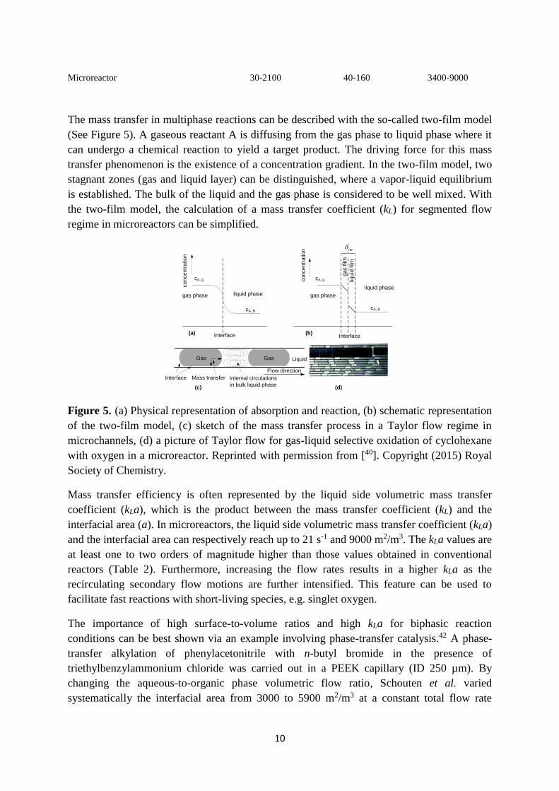
The mass transfer in multiphase reactions can be described with the so-called two-film model
(See Figure 5). A gaseous reactant A is diffusing from the gas phase to liquid phase where it
can undergo a chemical reaction to yield a target product. The driving force for this mass
transfer phenomenon is the existence of a concentration gradient. In the two-film model, two
stagnant zones (gas and liquid layer) can be distinguished, where a vapor-liquid equilibrium
is established. The bulk of the liquid and the gas phase is considered to be well mixed. With
the two-film model, the calculation of a mass transfer coefficient (kL) for segmented flow
regime in microreactors can be simplified.
Figure 5. (a) Physical representation of absorption and reaction, (b) schematic representation
of the two-film model, (c) sketch of the mass transfer process in a Taylor flow regime in
microchannels, (d) a picture of Taylor flow for gas-liquid selective oxidation of cyclohexane
with oxygen in a microreactor. Reprinted with permission from [40]. Copyright (2015) Royal
Society of Chemistry.
Mass transfer efficiency is often represented by the liquid side volumetric mass transfer
coefficient (kLa), which is the product between the mass transfer coefficient (kL) and the
interfacial area (a). In microreactors, the liquid side volumetric mass transfer coefficient (kLa)
and the interfacial area can respectively reach up to 21 s-1 and 9000 m2/m3. The kLa values are
at least one to two orders of magnitude higher than those values obtained in conventional
reactors (Table 2). Furthermore, increasing the flow rates results in a higher kLa as the
recirculating secondary flow motions are further intensified. This feature can be used to
facilitate fast reactions with short-living species, e.g. singlet oxygen.
The importance of high surface-to-volume ratios and high kLa for biphasic reaction
conditions can be best shown via an example involving phase-transfer catalysis.42 A phase-
transfer alkylation of phenylacetonitrile with n-butyl bromide in the presence of
triethylbenzylammonium chloride was carried out in a PEEK capillary (ID 250 µm). By
changing the aqueous-to-organic phase volumetric flow ratio, Schouten et al. varied
systematically the interfacial area from 3000 to 5900 m2/m3 at a constant total flow rate
Liquid
Internal circulations
in bulk liquid phase
Interface
Gas Gas
Flow direction
Interface
gas phase liquid phase
cA, g
cA, B
Interface
liquid phase
gas phase
cA, g
cA, B
liqu
id film
ga
s film
co
nce
ntr
atio
n
co
nce
ntr
atio
n
(a) (b)
(c)
Mass transfer
(d)
int

11
(Table 3). This resulted in an overall increase of the kLa value from 0.24 to 0.47 s-1 and,
consequently, in a substantial enhancement of the conversion from 40 to 99%.
The high reproducibility of the interfacial area and the flexibility of biphasic microreactors
has been used to evaluate the “on water” effect for the cycloaddition of olefins with diethyl
azodicarboxylate.43 The precise control over important process parameters, e.g. interfacial
area, flow rate, residence time, allowed to study the kinetics and the activation energies of
this reaction with high precision. This is very difficult to achieve with classical multiphase
reactors as there is little to no control over the interfacial area.
Table 3. Influence of the surface-to-volume ratio and the kLa on the conversion of phase-
transfer alkylation of phenylacetonitrile with n-butyl bromide.
aqueous-to-organic phase
volumetric flow ratio
average organic
slug length
(µm)
average
surface-to-
volume ratio
(m2/m3)
kLa
(ml3mr
-3s-1)
Conversion
(%)
1.0 467 3000 0.24 40
2.3 330 4500 0.36 74
4.0 295 5100 0.41 92
6.1 265 5900 0.47 99
A further increase in interfacial area can be obtained by using packed-bed microreactors
(Figure 6). These reactors often have characteristic dimensions of several millimeters but the
interstitial voids between the particles can be categorized as microchannels. The superficial
velocity U0, i.e. the velocity in the open tube, can be easily calculated by dividing the
volumetric flow rate with the cross sectional area. The interstitial velocity, i.e. the velocity of
the fluid in the pores of the bed, will be much higher due to fluid continuity. If the porosity is
isotropic, the relation between superficial velocity and the interstitial velocity can be
calculated with the knowledge of the void fraction or porosity (ε):
0UU
(8)

12
Figure 6. Schematic representation of a packed-bed microreactor and the difference between
superficial velocity and interstitial velocity.
With a porosity of 0.3, it can be easily calculated that a 50 µL/min volumetric flow rate
results in an interstitial flow rate of 167 µL/min. This is a substantial increase, which results
improved mass transfer characteristics for multiphase flow compared to a segmented flow
regime.44-46 The immiscible fluids flow into confined interstices at high flow rates. This
causes an increased shear between the fluids and results in a good dispersion, resulting in
higher mixing efficiency and mass transfer rates.47, 48 A modified Reynolds number (RePB)
can be identified, which is used to identify the boundaries of the different flow regimes in a
packed-bed:
0Re
(1 )
pd U
(9)
where dp is the spherical particle diameter, ρ the density of the fluid, µ is the viscosity of the
fluid and ε is the porosity. The boundaries for the different flow regimes in a packed-bed
microreactor include a laminar regime (RePB < 10), a transitional regime (10 < RePB < 300),
and a turbulent regime (RePB > 300).49
Packed-bed microreactors have been widely used to reduce the reaction times in multiphase
reaction conditions. The bed is typically an inert material which is merely used to intensify
the surface area between the two immiscible phases. Examples using organometallic catalysts
in biphasic packed-bed microreactors are Buchwald-Hartwig aminations,50 α-arylations,51
Suzuki-Miyaura cross-coupling reactions,52, 53 nitration54 and adipic acid synthesis.55, 56 The
packed bed can also be made out of catalysts, reactants or scavengers.57 This results often in a
high increase of the reaction rate as a large excess is available.58 One point of attention is the
activity of the bed which can decrease over time due to catalyst leaching or degradation,59
deposition of by-products or complete consumption of the immobilized reagents.60 The
packed-bed can even be used as a heating device via inductive heating61 or microwave
heating,62 which allows very fast heating of the reaction mixture.
In packed-bed microreactors, a high resistance for fluid flow is encountered, which results in
a high pressure drop over the bed. It is important to understand that a higher pressure drop
requires a higher energy input from the pumps to overcome this barrier, e.g. HPLC pumps are
suitable in most cases. The pressure drop over the packed bed can be calculated according to
Darcy’s law:
P Q
L A
(10)
where Δp is the pressure drop, Q is the volumetric flow rate, L is the length of the bed, µ is
the viscosity of the fluid, ĸ is permeability of the bed, and A is the cross section. From this
equation, it is clear that the pressure drop will increase linearly with increasing flow rates and
lengths of the packed bed. Further, the pressure drop will decrease with increasing
permeability of the bed. In other words, smaller particles will result in high pressure drops as
13
the porosity of the bed decreases with decreasing particle size. It is also important to have a
narrow particle size distribution to ensure a high permeability; smaller particles can fill up the
pores between larger particles resulting in a lower permeability of the bed. Large pore
volumes (1-2 mL/g) can be found in monolith microreactors, where the permeability is high
and the fluid encounters low resistance.63, 64
For gas-liquid and liquid-liquid biphasic reaction conditions, the Hatta number (Ha) can be
calculated which compares the rate of reaction in the liquid film to the rate of diffusion
through the film:
1
, n , ,
2( ) ( )
1
m n
m A i B bulk A
L
k c c Dm
Hak
(11)
where km,n is the reaction rate constant, CA,i is the concentration of A at the interface, CB,bulk is
the concentration of component B in the bulk of the liquid, DA is the diffusivity of A and kL is
the liquid side mass transfer coefficient. The value of Ha can be used to evaluate the extent of
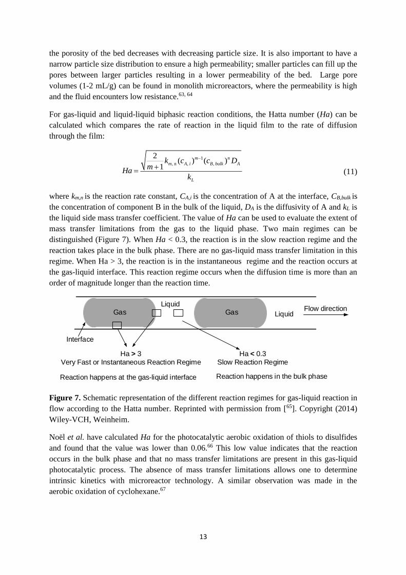
mass transfer limitations from the gas to the liquid phase. Two main regimes can be
distinguished (Figure 7). When Ha < 0.3, the reaction is in the slow reaction regime and the
reaction takes place in the bulk phase. There are no gas-liquid mass transfer limitation in this
regime. When Ha > 3, the reaction is in the instantaneous regime and the reaction occurs at
the gas-liquid interface. This reaction regime occurs when the diffusion time is more than an
order of magnitude longer than the reaction time.
Figure 7. Schematic representation of the different reaction regimes for gas-liquid reaction in
flow according to the Hatta number. Reprinted with permission from [65]. Copyright (2014)
Wiley-VCH, Weinheim.
Noël et al. have calculated Ha for the photocatalytic aerobic oxidation of thiols to disulfides
and found that the value was lower than 0.06.66 This low value indicates that the reaction
occurs in the bulk phase and that no mass transfer limitations are present in this gas-liquid
photocatalytic process. The absence of mass transfer limitations allows one to determine
intrinsic kinetics with microreactor technology. A similar observation was made in the
aerobic oxidation of cyclohexane.67
Ha > 3
Very Fast or Instantaneous Reaction Regime
Reaction happens at the gas-liquid interface
Ha < 0.3
Slow Reaction Regime
Reaction happens in the bulk phase
Liquid
Liquid
Interface
Gas GasFlow direction

14
4. Heat transport phenomena
An adequate energy management is crucial in the design of any reactor to guarantee a high
yield and selectivity.68 This is especially mandatory for highly exothermic reactions, in which
uncontrolled heat generation can lead to thermal runaways and ultimately to explosions. For
any chemical reaction, the classical heat balance can be used without considering the effect of
axial dispersion:
( )( ) cR
P P
U a T -Tr HdT dT
dV S dz mC mC
(12)
where T is the temperature of reaction mixture, V is the reactor volume, S is the cross-
sectional area, z is the reactor length along the flow direction, a is the specific heat-exchange
surface, ΔHR is the reaction enthalpy, CP is the mean specific heat capacity of the reaction
mixture, and U is the global heat-transfer coefficient. The first item on the left describes the
variation of the temperature along the flow direction. The first item on the right describes the
rate of heat generated through reaction and the second item represents the rate of heat
removed through the channel wall.
One of the most important design parameters for a chemical reactor is the adiabatic
temperature rise (ΔTad), which represents the worst case scenario of heat generation. ΔTad is
the increase in reaction temperature as a result of an exothermic reaction in the absence of
any heat dissipation to the environment. In other words, this is the maximum temperature
increase one can expect and its value is used to design the chemical reactor and to incorporate
appropriate safety measures. ΔTad is given by the following equation:
s,0 ( )R
ad
p
c HT
C
(13)
where cs,0 is the inlet concentration of the substrate and ρ is the mean density of the reaction
mixture.
The temperature profile in a chemical reactor is in reality depending on the global heat
transfer coefficient (U), which accumulates all heat transfer resistances and can be expressed
as follows:
1 1 1( )
2
out h
in wall m out out
d d a a
U h a h a
(14)
The first item describes the resistance between the channel wall and reaction mixture, the
second item represents the resistance of channel wall, and the third item expresses the
resistance located between the outer wall and the cooling fluid. The convective heat-transfer
coefficients (hin and hout) are related to the hydrodynamics and the hydraulic diameter of
reactors, which can be calculated through the Nusselt number (Nu):69

15
0.8
0.467
0.19( )/ [3.65 ] /
1 0.117( )
h
in fluid h fluid h
h
Re Pr dh Nu d d
Re Pr d
(15)
According to this correlation, a reduction of the hydraulic diameter (dh) will result in an
increase of the heat-transfer coefficient (Figure 8). This in combination with the large heat-
transfer surface area makes that microreactors are ideally suited for heat exchange purposes.
This was already realized in 1981 by Tuckerman and Pease in their landmark paper on micro
heat exchange.70 They reported that heat dissipation up to 790 W/cm2 was possible for a
single-phase water-cooling system, which was used for cooling integrated circuits. Since then
many different applications of micro heat exchangers have been realized, e.g. in automotive
industry, electronic industry, and microreactor technology.71
Figure 8. Effect of the hydraulic diameter d on the heat transfer coefficient h.
To ensure a proper energy balance within the chemical reactor, it is crucial to ensure that the
heat removal rate is at least equal to the heat generation rate. This means that the ratio of heat
generation rate to the heat removal rate should be lower than 1.
heat generation rate1
heat removal rate 6
R h
ad in
r H d
T h
(16)
Due to the high surface-to-volume ratio, material properties and surface characteristics of the
microchannels play a dominant role in the heat exchange efficiency.72 Circular channels give
the best thermal and hydrodynamic performance, while rectangular channels are still often
used due to the ease of manufacturing. The heat exchange efficiency can further be
intensified by increasing the surface area through heat pin-fins or channel curvature.73 But
also the channel material is important as described in equation 14; higher conductivities result
in a higher global heat-transfer coefficient (U) (Table 4). The choice of material is given in
by (i) the availability and cost of the material, (ii) the ease of handling of the material and
manufacturing process, (iii) the thermal conductivity, (iv) the surface roughness of the
material, and (v) the operational conditions. Stainless steel is often used to make
microreactors as it is cheap and can resist high pressure and temperature.74 It provides a high
heat conductivity, however, it is not compatible with acidic media due to corrosion. Silicon

16
microreactors are used owing to their favorable thermal conductivity and ease of
manufacturing.75 The latter can be attributed to a broad availability of micromachining
techniques from the silicon and computing industry. Silicon microreactors can withstand high
temperatures and pressures and provide chemical resistance to a broad range of chemicals.
However, strong alkaline reaction mixtures can erode the channels, which can be overcome
by special surface treatments.34 The use of polymer-based microreactors, such as the
widespread PFA and FEP capillaries, are less suited for heat exchange purposes considering
their low thermal conductivity. However, they are still used a lot in micro flow chemistry
applications as a result of their easy fabrication, low cost and high chemical stability.
Furthermore, due to the optimal light transparency properties, the use of polymeric
microreactors is advantageous for photochemical applications.65, 76 Aluminum alloys are
mostly used to fabricate micro heat exchangers in the automotive and thermal industry by
virtue of their lower weight compared to stainless steel.77 Silicon carbide has a very high
thermal conductivity and an exceptional chemical stability.78 However, this material is quite
expensive and brittle. Therefore, it is mainly used for highly exothermic reactions, where a
high heat dissipation rate is desired.
Table 4. Thermal conductivity of some materials commonly employed for the fabrication of microreactors.
Material Thermal Conductivity [W m-1 K-1]
PFA 0.195 FEP 0.19-0.24 Glass 1 Stainless Steel 12–45 Silicon 149
Aluminum 237 (pure)
120–180 (alloy)
Silicon Carbide 120-490 Copper 401
The use of microreactors is especially interesting for fast and highly exothermic reactions (-
ΔHR > 50 kJ/mol).79 In batch, such reactions are typically conducted under sub-optimal
reaction conditions, meaning that the reaction is cooled substantially to slow down the
reaction kinetics and thus to minimize the concomitant heat generation (see discussion DaII).
Intriguing examples, where the reaction can be carried out at higher temperatures in flow, are
transmetallation reactions. As can be seen from Figure 9, the monolithiation of 1,2-
dibromobenzene needs careful temperature control to provide high selectivity.80 Hot spot
formation leads in batch to the formation of benzyne and derived by-products. Consequently,
the reaction needed to be cooled down to -100 ºC to obtain decent yields. In flow, the reaction
could be carried out at -70~-75 ºC thanks to the improved heat and mass transfer
characteristics by using stainless steel micromixers and reactor coils. The heat production is
the highest at the mixing zone where the reactants are merged. Depending on the
exothermicity of the reaction (ΔTad), the formation of hot spots is still possible with
instantaneous reactions even when one is using a microreactor. An interesting strategy to
avoid formation of hot spots is to spread the heat production by multi-injection of the

17
reactants along the reactor length.81 The extent of the hot spot can be minimized by
increasing the amount of injections. An application of this multi-injection protocol was the
Grignard reaction between phenylethylmagnesium bromide and 2-chloropropionyl chloride.82
A four-injection strategy was sufficient to temper the exotherm of the reaction and allowed to
increase the selectivity of the reaction up to 50% yield. Furthermore, the heat management in
microreactor systems can also be improved by applying a multi-stage temperature ramping
approach.56 The main characteristics of this approach are to use various temperatures in
different sections of the reactor according to the reaction properties. This strategy allows to
avoid hot spot formation throughout the microreactor, which is particularly useful for
reactions involving thermal decomposition of reactants (e.g. adipic acid synthesis from
cyclohexene and hydrogen peroxide). The use of multiphase reaction streams, e.g. segmented
flow, can also intensify the heat dissipation which provides a high degree of control over the
selectivity of the reaction. Notable examples are oxidations,56 hydrogenations,83 nitrations,84
hydroformylations85 and direct fluorinations.86, 87
Figure 9. Contourplot which visualizes the correlation between the reaction temperature,
residence time and the yield of bromobenzene. Reprinted with permission from [80].
Copyright (2007) American Chemical Society.
Some organic reactions need harsh conditions, including high temperatures and pressures, to
provide substantial conversions. In batch, such reactions were typically carried out in
autoclaves or microwave reactors.88, 89 However, the use of an autoclave involves complex
reactor design and raises important safety issues. The use of microwave reactors remains
limited as scalability is hampered because of the limited penetration depth of the irradiation.90

18
In microreactors, often a rapid heating can be achieved due to the small characteristic length
scales. The fast heat transfer even allows to carry out reactions in the absence of any solvent,
highlighting the green aspect of continuous-flow processing in microreactors.91-93 An even
faster heat transfer can be achieved by using microwave94 or induction heaters.95 Microwave
heating is enabled by absorbance of the energy due to interaction of dipoles with the
microwaves. The rate of microwave heating is determined by the dielectric constant of the
solvent. Selective heating can also occur through coupling with immobilized catalysts, which
are either deposited on the reactor walls or used as a packed bed.62, 96 The use of microwave
heating can be beneficial for heating mesoscale flow reactors (> 1 mm) as the efficiency of
microwave energy transfer increases with larger diameters.97, 98 Induction heating can heat
packed-bed reactors very fast due to generation of eddy currents in electrically conducting
objects via a constantly changing electromagnetic field (Joule heating). The magnetic
nanoparticles can be decorated with catalysts and thus selective heating takes place where the
reaction occurs.61 Interestingly, by using back pressure regulators, reaction solvents can be
heated above their boiling point (super heating). Furthermore, solvents or gasses can be
heated and pressurized above their critical point furnishing supercritical reaction
conditions.99-101 Supercritical conditions provide reduced viscosity and interfacial tension,
improved diffusivities and increased gas solubility.
5. Photon transport phenomena
The use of photons to initiate chemical reactions has been known for decades in organic
synthetic chemistry.102-104 It provides opportunities to carry out remarkable reactions which
are otherwise difficult to realize with classical thermochemical approaches. In recent years, a
new wave in photochemistry has emerged in which visible light photoredox catalysis has
been recognized as a mild and selective way of small molecule activation.105-107 The use of
photons as “traceless reagents” abides to the green chemistry principles; in the absence of any
reaction, the starting material can be recovered when it returns to its ground state.
Nevertheless, many engineering challenges are associated with photochemical processes and
these can be often attributed to the Lambert-Beer limitation (attenuation effect of photon
transport).108 Many of these issues can be overcome by using continuous-flow
photomicroreactors.65, 76, 109-112
Photochemical processes are initiated by the absorption of photons. Thus, conversion and
yield are highly depending on the energy distribution within the reactor. In photochemical
reactors, a gradient in photon absorption exists which is due to absorption or light scattering.
In order to maximize the efficiency of the photochemical reactor, it is important that the
radiation distribution is as homogeneous as possible. The radiation distribution can be
represented by the spectral specific intensity (I) and gives the amount of irradiative energy
through a unit area per unit wavelength per unit time.
, , ,
( , , , ) ( )cos
limdA d dt d
dEI s t
dA d dtd
(17)

19
where dEλ is the total amount of irradiative energy passing through a unit area in the time dt
and within a wavelength range between λ and λ+dλ. Integrating the spectral specific intensity
over the reactor surface provides the incident radiation (Gλ).
,( , ) ( , )G s t I s t d
(18)
The local volumetric rate of energy absorption (LVRPA) is an important parameter
depending on the design of the photoreactor, the light source intensity, the photophysical
properties of the reaction mixture. Due to absorption and light scattering, the LVRPA is not
uniform. Considering the small length scales, the non-uniformity of the LVRPA can be
minimized in a microreactor.
( , ) ( , )LVRPA s t G s t (19)
where is the volumetric absorption coefficient that represents the fraction of the incident
radiation that is absorbed by the matter per unit length along the path of the beam. However,
even when the photons are absorbed by the reaction medium, not every absorbed photon will
give rise to one reaction event. The excited state can return to its ground state through
radiative or non-radiative (e.g. heat generation) processes. The efficiency of the
photochemical process can be given by the quantum yield:
P number of molecules formed
number of photons absorbed by reactive medium
(20)
The quantum yield typically varies between 0 to 1.0. Φ > 1 typically indicates that a chain
reaction occurs, e.g. polymerizations can have Φ > 104.113, 114 Quantum yields can be
determined by measuring first the photon flux with chemical actinometry115 and subsequently
carrying out the reaction in the same photochemical setup. The photon flux is defined as
follows:
photon fluxG
hc
(21)
where h is the Planck’s constant, and c is the speed of light in vacuum, respectively. Loubiere
et al. have reported on the measurement of photon fluxes in photomicroreactors.116 It is
important to note that the energy emitted by the light source is not equal to the photon flux
through the reaction medium, i.e. not every photon emitted by the light source will travel
through the reactor. The authors compared the photon flux for a microreactor and a batch
reactor. The batch reactor received 7.4 10-6 einstein/s, while the microreactor acquired a
photon flux of 4.07 10-6 einstein/s. However, the absorbed photon flux density (Φ/Vr) was
much higher for the microreactor: compare 5.02 einstein/(m3.s) to 0.033 einstein/(m3.s) for
the batch reactor. This 150-fold higher absorbed photon flux density explains clearly the
substantial rate accelerations that are typically observed in microreactors.
The photonic efficiency (ξ) of a reactor can be defined as follows:

20
rate of the reaction
photon flux
(22)
The photonic efficiency (ξ) in microreactors (ξ = 0.0262)117 is about one order of magnitude
higher than those in batch reactors (ξ = 0.0086-0.0042).118 This value can be further improved
by using microscale light sources (e.g. LEDs), which matches the dimensions of the
microchannels, or the optimization of light propagation with the help of optical fibers or
mirrors as light reflectors.119 By using LEDs and a capillary microreactor, Noel et al. were
able to further increase the photonic efficiency to 0.66 representing an 160 fold improvement
compared to batch photoreactors.120
A full description of photon transport phenomena is quite complex and is beyond the scope of
this review.121 For monochromatic light, photon transport can described according to the
following equation:
''
, , ' '
, , ,4
( , ) ( , )( , ) ( , ) ( , ) ( , ) ( , ) ( ) ( , )
4
Absorption out-scattering Emission in-scattering
edI s t s t
k s t I s t s t I s t j s t p I s t dds
(23)
This equation describes all relevant phenomena which can be encountered in photochemical
processes, including absorption, emission and scattering effects. Emission effects can be
neglected when the reaction is carried out at low reaction temperatures. For homogeneous
reaction mixtures, also scattering effects can be minimized and if the light intensity is kept
constant and propagates unidirectional, the equation can be simplified to:
,
,
( )( ) ( )
dI sk s I s
ds
(24)
Integration of this equation results into the well-known Bouguer-Lamber-Beer law for photon
transport:
0
10 10log logI
A T clI
(25)
This equation displays the dependence of the absorption on the molar extinction coefficient
(ε), the concentration of absorbing species (c) and the path length of light propagation (l). The
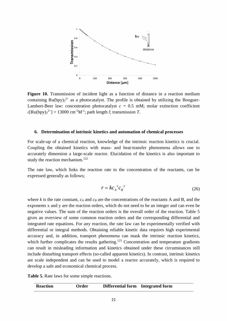
importance of the length scale in photochemistry can be clearly shown by plotting this
equation for a relevant photocatalytic reaction using Ru(bpy)32+ (0.5 mM) as a photocatalyst,
as shown in Figure 10. After 500 µm, already 50% of the light intensity is absorbed by the
photocatalyst. It should be noted that in some reactions the catalyst loading and the molar
extinction coefficient can be even higher. This clearly demonstrates the importance of using a
photomicroreactor to provide sufficiently high photon fluxes through the entire reaction
medium.
21
Figure 10. Transmission of incident light as a function of distance in a reaction medium
containing Ru(bpy)32+ as a photocatalyst. The profile is obtained by utilizing the Bouguer-
Lambert-Beer law: concentration photocatalyst c = 0.5 mM; molar extinction coefficient
ε[Ru(bpy)32+] = 13000 cm-1M-1; path length l; transmission T.
6. Determination of intrinsic kinetics and automation of chemical processes
For scale-up of a chemical reaction, knowledge of the intrinsic reaction kinetics is crucial.
Coupling the obtained kinetics with mass- and heat-transfer phenomena allows one to
accurately dimension a large-scale reactor. Elucidation of the kinetics is also important to
study the reaction mechanism.122
The rate law, which links the reaction rate to the concentration of the reactants, can be
expressed generally as follows;
x y
A Br kc c
(26)
where k is the rate constant, cA and cB are the concentrations of the reactants A and B, and the
exponents x and y are the reaction orders, which do not need to be an integer and can even be
negative values. The sum of the reaction orders is the overall order of the reaction. Table 5
gives an overview of some common reaction orders and the corresponding differential and
integrated rate equations. For any reaction, the rate law can be experimentally verified with
differential or integral methods. Obtaining reliable kinetic data requires high experimental
accuracy and, in addition, transport phenomena can mask the intrinsic reaction kinetics,
which further complicates the results gathering.123 Concentration and temperature gradients
can result in misleading information and kinetics obtained under these circumstances still
include disturbing transport effects (so-called apparent kinetics). In contrast, intrinsic kinetics
are scale independent and can be used to model a reactor accurately, which is required to
develop a safe and economical chemical process.
Table 5. Rate laws for some simple reactions.
Reaction Order Differential form Integrated form

22
A P zeroth [A]dk
dt
0[A] [A] kt
A P first [A][A]
dk
dt
0ln[A] ln[A] kt
A A P second 21 [A]
[A]2
dk
dt
0
1 12
[A] [A]kt
A B P second [A][A][B]
dk
dt
0
0 0 0
[B] [A]1ln
[B] [A] [A] [B]kt
The use of microreactor technology for estimating reaction kinetics has been demonstrated by
many authors. Owing to the improved mass- and heat-transfer characteristics, intrinsic kinetic
data can be extracted from the experiments. An isothermal operated microreactor is required
to determine intrinsic kinetics for highly exothermic or endothermic reactions.124 The high
degree of reproducibility on experimental data in microflow provides better accuracy than
obtained in conventional batch reactors. This is especially the case for gas-liquid reactions,
where the poorly defined interfacial area in batch increases the error on the kinetic data.125 In
addition, the typical small reactor volumes make that the consumption of chemicals remains
small, making the use of microreactors for kinetic studies cost efficient.126 Inline
spectroscopical detection systems can be combined with microreactor technology and
maximizes the information content of each experiment.127 One of the major advantages of
batch kinetics is that it allows to generate a lot of data in a single experiment by collecting
several data points over time. Time-series data can be obtained in microflow reactors by
using a controlled ramp of the flow rate and inline analysis methods.128, 129
Obtaining reaction kinetics can be a time-consuming undertaking and, recently, a lot of effort
has been devoted to develop completely automated systems.130 This allows to reduce the
manual labor, to increase the efficiency of results collection and to implement Design of
Experiment methods (DOE).131 This approach has been used to optimize the Mizoroki-Heck
coupling between 4-chlorobenzotrifluoride with 2,3-dihydrofuran in a microreactor (Figure
11).132 An inline HPLC was used to measure the yield and the selectivity of the reaction. This
information was analyzed by a computer and feedback control was delivered with regard to
the reagent concentration and residence time. As such, a rapid optimization (19 experiments
in total) of the reaction parameters was carried out in a time-efficient fashion with no
additional manual labor, allowing to minimize the total amount of chemical consumption.
These reaction conditions were subsequently scaled in a meso-scale reactor requiring no
additional optimization. Similar automated approaches were used to determine the reaction
kinetics of various chemical reactions133, 134 and to perform multistep sequences in
combination with purification steps.135

23
Figure 11. Schematic representation of a “self-optimizing” microfluidic platform for the
Mizoroki-Heck coupling between 4-chlorobenzotrifluoride with 2,3-dihydrofuran in a
microreactor. The obtained results could be subsequently scaled up in a mesoscale reactor.
Reprinted with permission from [136]. Copyright (2014) Wiley VCH, Weinheim.
For photochemical reactions, the intrinsic reaction rate strongly depends on the local
volumetric rate of energy absorption (LVRPA) and the quantum yield (Φ). For a simplified
A→B reaction and under plug flow behavior, the rate equation can be described as
follows:137
( )r LVRPA
(27)
For the photocatalytic aerobic oxidation of thiols to disulfides,138 Noël et al. have
investigated the effect of the photon flux on reaction yield: a clear effect can be seen on the
reaction rate constant (Figure 12).66, 120 At low photon fluxes, no difference is noticed
between a high and a low catalyst loading (Figure 12a). This indicates that the reaction occurs
under a photon limited regime and the photons are constantly consumed to excite the
photocatalyst. Based on the experimental results, a correlation for the reaction rate constant
could be derived which demonstrates its dependence on the catalyst loading and photon flux.
0.56 0.21228.6subk q
(28)
At a high catalyst loading, the yield or the reaction rate increased with increasing the
effective energy input for a photochemical process (Figure 12b). The relationship between

24
the yield and the effective energy input was found to be generally linear at various residence
times.
(a) (b)
Figure 12. Photocatalytic aerobic oxidation of thiols to disulfides: (a) Dependence of the
reaction rate constant on the photon flux. (b) Relationship between the yield and the effective
energy input at 1% photocatalyst loading. Reprinted with permission from [120]. Copyright
(2015) Wiley VCH, Weinheim.
7. Safety aspects
Increased safety of chemical processing is one of the main drivers to implement continuous-
flow processing in the industry.139 The small dimensions of a typical microreactor provide
opportunities to process small amounts of hazardous material and, therefore, minimizes the
risks associated with its handling.79
The power of an explosion is proportional to the mass of the explosive mixture in the reactor
with the power of 1/3. This directly explains why microreactors are inherently safe to use on
a laboratory scale and to carry out explosive reaction conditions. However, it is important to
note that an explosion can propagate to the mixing chamber or the collection vessels where
often the inventory of flammable material is much larger.140, 141 It has been demonstrated that
explosion propagation occurs when the tube diameter is larger than λ / π , where λ represents
the detonation cell width and can be calculated from the induction length.142 This is the so-
called λ / 3 rule which has been originally validated for macroscopic tubes. This rule can be
used to calculate the diameter of the microreactor in which safe processing of the reaction
mixture can be done. For an ethane/oxygen mixture it was found that the diameter had to be
lower than 0.1 mm to avoid explosion propagation.142 Although microreactors cannot be
regarded as inherently safe, the range of safe operating conditions can be substantially
increased as the upper explosion limit is lowered (Figure 13). The potential of explosion
propagation also demonstrates the necessity to quench a reaction adequately upon exiting the
reactor. It has been shown by several authors that hazardous intermediates can be generated
0
50
100
150
200
250
300
0 25 50 75 100 125 150
ksu
b/
(sM
2)-1
photon flux (mol/s)
1% Eosin Y loading
0.25% Eosin Y loading
0
10
20
30
40
50
60
70
80
90
100
0 0.1 0.2 0.3 0.4 0.5 0.6
Y (
%)
effective energy input (W)
86 s56 s42 s28 s

25
in situ and subsequently reacted away in a follow up reaction.143 Kappe et al. demonstrated
elegantly this principle in the synthesis of tetrazoles (Figure 14).144 Hydrazoic acid (HN3), an
extremely toxic compound, was prepared in situ in a microreactor and consumed immediately
by reaction with a nitrile to prepare the corresponding tetrazoles. The reaction was
subsequently quenched with NaNO2 to decompose any residual hydrazoic acid. This allows
to minimize the total inventory of hazardous compounds and thus to reduce the associated
risks.
Figure 13. Explosive behavior of mixtures of ethene with oxygen. A reduction of the
explosion regime can be noticed when working in a microreactor. Reprinted with permission
from [140]. Copyright (2012) Elsevier.
Figure 14. Continuous-flow synthesis of tetrazoles by preparing in situ HN3 and quenching
with NaNO2.
Thermal explosions are caused by an exponential increase of the reaction rate according to
the Arrhenius equation with rising temperatures. This leads to a further increase in
temperature and eventually to a reaction runaway. The increase in temperature and pressure
at runaway conditions can ultimately lead to a reactor rupture and thus explosion. This is
26
called parametric sensitivity; hereby, a small deviation of a parameter can lead to a chain of
reaction events where the reaction rate and temperature increase in an incontrollable
fashion.145 Due to the high surface-to-volume ratios fast heat transfer is possible leading to
isothermal conditions in microreactors. Accordingly, for highly exothermic reactions, the
conductivity of the reactor material plays an important role. Excellent heat dissipation in
combination with high surface-to-volume ratios minimizes the risk of thermal runaways
compared to large batch reactions.146 However, local hot spots can still occur, e.g. in catalyst
beds,147 which can serve as an ignition source.148-151
Surface effects are also important as they can initiate the decomposition of compounds, e.g.
steel reactors can initiate radical formation.152, 153 Kinetic explosions can take place where
radicals are uncontrollably formed. Termination of the radical chain reaction can typically
occur at the reactor surface. Consequently, the short length scales encountered in
microreactors leads to fast diffusion of the radicals to the reactor walls, tempering efficiently
such chain reactions.154
8. Solids handling in flow
The handling of solids remains one of the major obstacles for continuous-flow microreactor
technology.16, 155, 156 Solid materials can aggregate or deposit on the reactor walls, which
leads to channel blockage and prevents fluid from flowing. The presence of solids in a
reaction stream can have several origins, including solid starting materials and generation of
precipitation during the reactions by forming insoluble products or by-products. The nature of
the solid and its origin warrant a case-by-case strategy to overcome potential channel
blockage.
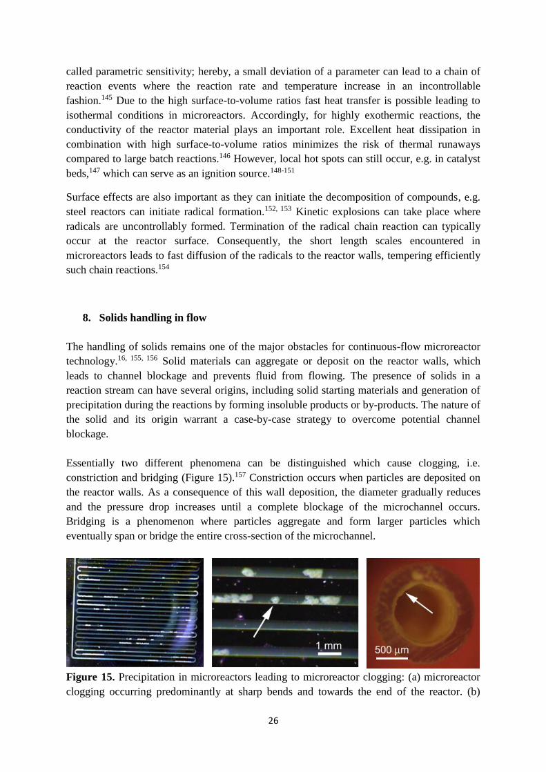
Essentially two different phenomena can be distinguished which cause clogging, i.e.
constriction and bridging (Figure 15).157 Constriction occurs when particles are deposited on
the reactor walls. As a consequence of this wall deposition, the diameter gradually reduces
and the pressure drop increases until a complete blockage of the microchannel occurs.
Bridging is a phenomenon where particles aggregate and form larger particles which
eventually span or bridge the entire cross-section of the microchannel.
Figure 15. Precipitation in microreactors leading to microreactor clogging: (a) microreactor
clogging occurring predominantly at sharp bends and towards the end of the reactor. (b)

27
bridging due to particle growth. (c) wall deposition leading to constriction of the
microreactor. Reprinted with permission from [157]. Copyright (2010) American Chemical
Society.
Several strategies have been suggested in the literature to overcome microreactor clogging.
Probably the easiest strategy is to use polar solvents which can solubilize highly polar
products or inorganic salts. Examples of this strategy are biphasic reaction conditions in
which water is added as a second phase to dissolve inorganic salts.50, 53 Insoluble materials
can be transported through the microreactor channels as a slurry.158 However, this strategy
works best when a segmented flow regime is used where intensified mixing patterns in the
liquid slugs keep the particles in suspension and avoids interaction with the reactor walls.159
A popular strategy to deal with insoluble materials, such as heterogeneous catalysts, is
immobilization in a packed-bed reactor. This method is often used to avoid extensive
downstream purification procedures. Precipitation of highly polar compounds can be also
avoided by heating the reactor above the melting temperature of the solid material.91, 160
Consequently, the material is processed in its molten state and will not clog the
microchannels. Another strategy is to use mechanical energy to keep the solids in suspension.
A commercially available agitating cell reactor (Coflore ACR) utilizes this principle to avoid
clogging. The reactor consists of a series of continuous stirred tank reactors (CSTR) and was
used to prepare N-iodomorpholinium hydroiodide.161 Finally, ultrasound energy has been
increasingly used to facilitate the processing of solids forming reactions.162 Acoustic
irradiation induces cavitation at the particle surface. Upon implosion of the bubble, high
shear forces at the particle surface cause particle break-up. These smaller particles are small
enough to be transported through the microchannels. This strategy has been used to avoid
clogging in C–N cross coupling,163, 164 Suzuki-Miyaura coupling,165 photodimerization
reactions,166 KMnO4 oxidation reactions167 and other solids forming reactions.168, 169
9. Multistep synthesis
The synthesis of complex organic molecules is a time-consuming and resource-intensive
undertaking and represents a formidable challenge for synthetic organic chemists. A typical
synthesis of a complex biologically active compound consists of a sequence of different
reaction steps and intermediate purification steps. In recent years, many different strategies
have been developed to facilitate the preparation of such compounds, including
multicomponent reactions, cascade reactions, one-pot syntheses, protecting group free
syntheses and improved catalytic methodologies. These strategies are all focused on
improving the efficiency of the chemical transformation itself. However, a change in
processing strategy, e.g. from batch to continuous-flow processing, is much less considered
by most chemists.
The use of continuous-flow reactors allows to integrate subsequent reaction and purifications
steps in one single streamlined and automated process.170 Several strategies that facilitate
multistep reaction sequences have been developed throughout the years.171 A first strategy

28
includes a telescoping approach in which the individual reaction steps are linked together
without intermediate purification steps. This strategy is a convenient approach and resembles
the one-pot strategies encountered in batch in which reactants are sequentially and at certain
times injected in the flask. However, excess of reagents or by-products need to be compatible
with the downstream reactions. If these reagents or by-products are not compatible, a lower
conversion will be obtained than one would anticipate based on the individual reactions with
purified starting materials.
A purification of the reaction stream can be carried out to increase the overall efficiency of
the continuous-flow protocol. This can be achieved either by using immobilized catalysts,
reagents and scavengers or by incorporating unit operations.172 The first approach uses
packed-bed reactors in which the bed consist of beads with catalysts, reagents or scavengers.
By placing several cartridges in series, subsequent transformations in the preparation of
complex biologically active molecules can be carried out in a single flow operation. “Catch
and release” strategies are often employed to execute intermediate purifications, solvent
switches or to concentrate the intermediates. The need to periodically replace saturated
reagent cartridges is the main drawback of this approach and makes it most suitable for the
preparation of small amounts.
The use of unit operations to carry out separations is a very powerful approach since, in
theory, the process can be continuously operated without interruptions. However, the
development of such miniaturized unit operations has been challenging due to the fact that
interfacial forces dominate over gravitational forces. This is represented by the Bond number:
2gravityforce
interfacialforce
HgdBo
(29)
where σ denotes the surface tension, g is the gravitational acceleration, and ρ is the density,
and dH is the hydraulic diameter. In microchannels, the value of Bo is much lower than 1,
which means that one cannot use gravity to establish a phase separation. Alternatively,
extractions and distillations can be carried out by employing membrane technology based on
the utilization of capillary forces.173, 174 Consequently, microfluidic extractions,52, 175-180
distillations,181 and even simulated moving beds182, 183 have been developed and used in
combination with microreactors to enable a continuous purification of the reaction stream.
Several interesting multistep syntheses have been carried out in continuous-flow;184 an
overview of some notable examples are summarized in Table 6.

29
Table 6. Notable examples of multistep continuous-flow syntheses.
Biologically active compound Strategy Highlights Reference
Use of unit operations
- Pilot scale plant
- Continuous operation for 10 days
- 45 g/h of Aliskiren
- Reduction of number of unit
operations from 21 in batch to 14 in
flow
- Reduction total processing time from
300 h in batch to 47 h in flow
7
Use of immobilized
reagents
- 40% overall yield
- Seven separate steps in one
continuous process
- No intermediate purification
- One of the first examples at this level
of complexity
185
Use of immobilized
reagents
- Immobilization of chiral catalysts to
prepare chiral drug structures
- Chiral catalysts cartridges remain
stable for months without decrease in
enantioselectivity
186
Telescoping strategy
without intermediate
purification
- Includes a singlet oxygen
photochemical step
- Allows to produce 200g / day
artemisinin 187, 188
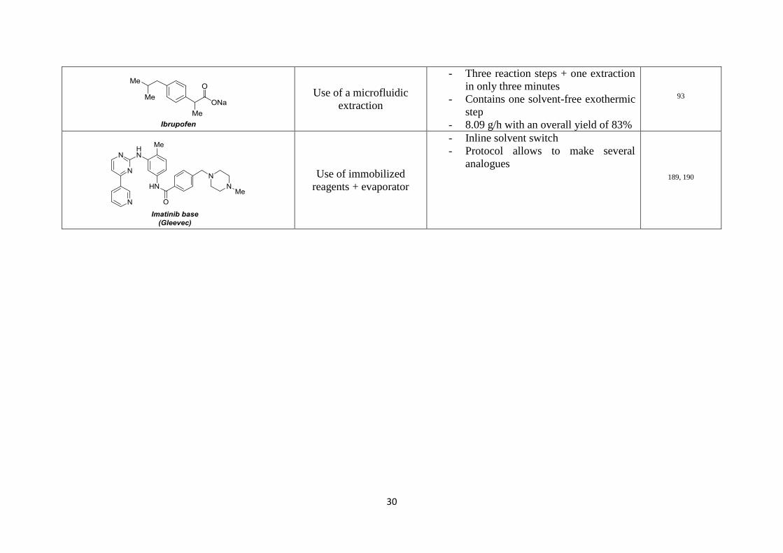
30
Use of a microfluidic
extraction
- Three reaction steps + one extraction
in only three minutes
- Contains one solvent-free exothermic
step
- 8.09 g/h with an overall yield of 83%
93
Use of immobilized
reagents + evaporator
- Inline solvent switch
- Protocol allows to make several
analogues
189, 190

31
10. Scalability
Leading a chemical route from a laboratory scale to a pilot or full production scale is a
challenging task for the process engineer. Often, the chemistry developed on a small scale is
not compatible with the large scale processing conditions, which need to take process safety
and cost efficiency into account. Furthermore, the hydrodynamics and transport properties
need to be maintained on each scale complicating the scale-up even more. Microreactor
technology has been hauled as a revolutionary technology which can overcome scaling
problems by simply putting multiple devices in parallel. However, this statement has been
overruled in recent years as it became evident that it was technologically far from easy to
achieve this. Several scale-up strategies with continuous-flow reactors can be distinguished:
1) longer operation times + increasing the throughput by using higher flow rates; 2)
numbering-up by placing several devices in parallel; 3) smart scale-out by a dimension
enlarging strategy.
The use of longer operation times is the strategy which is most used on a laboratory scale.
Reagents are continuously fed to the microdevice until the desired amount of product is
collected. The main advantage of this strategy is the simplicity and the use of the same device
for optimization and scale-up. Typically, several milligrams to a few hundreds of grams can
be obtained making the strategy ideally suited for the first stages of a drug discovery process.
Increasing the flow rate in microreactors is another way to increase the throughput. Longer
reactor lengths are used and thus higher flow rates are needed to keep the reaction time
constant. High flow rates result into improved transport properties (mixing and heat
dissipation), which can result in a reduction of the reaction time. It is important to note that
many reactions can already be substantially accelerated in a microreactor due to the excellent
transport properties, which allows to increase the throughput in a “natural” way. Examples of
reactions that can be substantially accelerated in microflow are gas-liquid reactions,
photochemical reactions, transmetallation reactions, electrochemical reactions and reactions
which require extreme reaction conditions (exothermic reactions and reaction at high
temperature and concentrations). Furthermore, the processing conditions that are used in
such devices can be easily translated to a larger scale process.132
Numbering-up of microreactors is the most common method to scale the throughput of a
single microreactor.191 Essentially two different methods can be distinguished, i.e. internal
and external numbering-up. Internal numbering-up is achieved by placing several
microchannels in parallel and using a single pumping and mixing unit. This reduces the
overall cost of the numbering-up strategy. The reaction stream is distributed equally over the
different microchannels by using a flow distributor. This requires an equal pressure drop over
the different parallel channels and is especially difficult to achieve for multiphase reaction
streams. Flow maldistribution can lead to great differences in performance between the

32
individual channels.192, 193 Schouten et al. have developed a barrier-based distributor manifold
for gas-liquid flows which allows to achieve a good distribution within ±10% in eight
different channels (Figure 16a).194 This manifold was subsequently demonstrated in the
numbering-up of a hydrogenation reaction.195 Noël et al. have developed a cheap and
straightforward numbering-up strategy for the photocatalytic aerobic oxidation of thiols to
disulfides.196 The system uses simple T-mixers as the basic flow splitting units to split up the
gas-liquid flow sequentially into eight different photomicroreactors (Figure 16b). The
deviation of the liquid throughput and the yield in the different channels was less than 10%.
The yield of the target product in the numbered-up system was comparable to those results
obtained in a single photomicroreactor. An impressive example of internal numbering-up was
realized by researchers from Velocys.197 A cross-flow heat exchanger configuration was used
to carry out a Fischer-Tropsch reaction; the reagents are directed over a heterogeneous
particulate catalyst, while boiling water was used to maintain an isothermal operation of the
reactor. The intrinsic kinetics of the reaction were studied in a single microchannel. Next, the
reaction was further scaled to a manufacturing device (see Figure 16c). This device (0.6 m x
0.6 m x 0.15 m) contained more than 10,000 microchannels and can produce up to 450 tons
of product per year. The flow distribution was excellent and showed a variability of less than
9%. Other examples of internal numbering-up are the falling film microreactor (Figure
16d)198 and multichannel microcapillary films.199
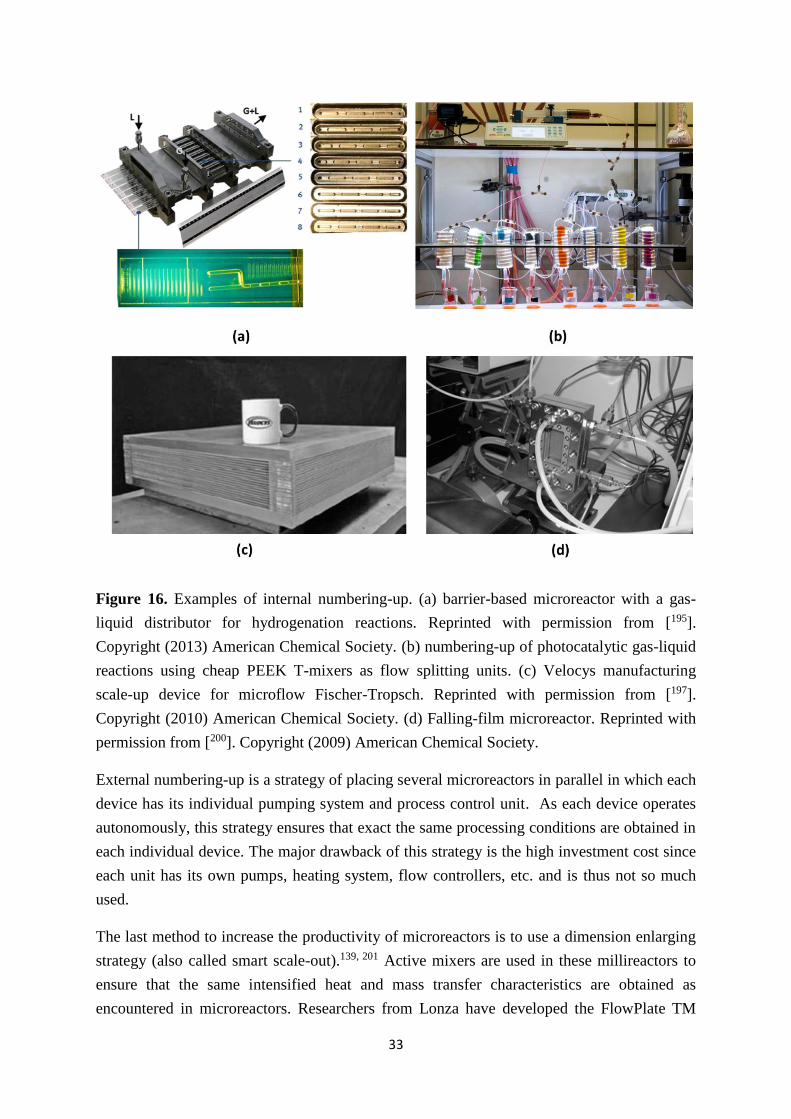
33
Figure 16. Examples of internal numbering-up. (a) barrier-based microreactor with a gas-
liquid distributor for hydrogenation reactions. Reprinted with permission from [195].
Copyright (2013) American Chemical Society. (b) numbering-up of photocatalytic gas-liquid
reactions using cheap PEEK T-mixers as flow splitting units. (c) Velocys manufacturing
scale-up device for microflow Fischer-Tropsch. Reprinted with permission from [197].
Copyright (2010) American Chemical Society. (d) Falling-film microreactor. Reprinted with
permission from [200]. Copyright (2009) American Chemical Society.
External numbering-up is a strategy of placing several microreactors in parallel in which each
device has its individual pumping system and process control unit. As each device operates
autonomously, this strategy ensures that exact the same processing conditions are obtained in
each individual device. The major drawback of this strategy is the high investment cost since
each unit has its own pumps, heating system, flow controllers, etc. and is thus not so much
used.
The last method to increase the productivity of microreactors is to use a dimension enlarging
strategy (also called smart scale-out).139, 201 Active mixers are used in these millireactors to
ensure that the same intensified heat and mass transfer characteristics are obtained as
encountered in microreactors. Researchers from Lonza have developed the FlowPlate TM
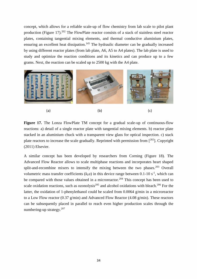
34
concept, which allows for a reliable scale-up of flow chemistry from lab scale to pilot plant
production (Figure 17).202 The FlowPlate reactor consists of a stack of stainless steel reactor
plates, containing tangential mixing elements, and thermal conductive aluminium plates,
ensuring an excellent heat dissipation.145 The hydraulic diameter can be gradually increased
by using different reactor plates (from lab plate, A6, A5 to A4 plates). The lab plate is used to
study and optimize the reaction conditions and its kinetics and can produce up to a few
grams. Next, the reaction can be scaled up to 2500 kg with the A4 plate.
Figure 17. The Lonza FlowPlate TM concept for a gradual scale-up of continuous-flow
reactions: a) detail of a single reactor plate with tangential mixing elements. b) reactor plate
stacked in an aluminium chuck with a transparent view glass for optical inspection. c) stack
plate reactors to increase the scale gradually. Reprinted with permission from [202]. Copyright
(2011) Elsevier.
A similar concept has been developed by researchers from Corning (Figure 18). The
Advanced Flow Reactor allows to scale multiphase reactions and incorporates heart shaped
split-and-recombine mixers to intensify the mixing between the two phases.203 Overall
volumetric mass transfer coefficients (kLa) in this device range between 0.1-10 s-1, which can
be compared with those values obtained in a microreactor.204 This concept has been used to
scale oxidation reactions, such as ozonolysis205 and alcohol oxidations with bleach.206 For the
latter, the oxidation of 1-phenylethanol could be scaled from 0.0064 g/min in a microreactor
to a Low Flow reactor (0.37 g/min) and Advanced Flow Reactor (4.08 g/min). These reactors
can be subsequently placed in parallel to reach even higher production scales through the
numbering-up strategy.207

35
Figure 18. Corning glass flow reactors: (a) Corning Low Flow Reactor (450 µL), (b) Corning
Advanced Flow Reactor (8.7 mL). Further scale-up by numbering-up. Reprinted with
permission from [206]. Copyright (2014) Wiley VCH (c) Further scale-up by numbering-up.
Reprinted with permission from [207]. Copyright (2011) Wiley VCH.
11. Conclusion
In this review, we have focussed on giving an overview of the most important engineering
principles which are relevant for chemists and chemical engineers to carry out flow
chemistry. We have tried to explain these fundamental aspects in a language that is
understandable for the synthetic chemist and have provided relevant chemical examples
illustrating the importance of these principles. Where relevant, we have directed the reader to
more detailed reviews. It is our hope that this review will become a handy tool for flow
chemists to recognize where continuous-flow microreactors can actually make a difference
and to exploit the full potential of the technology.
Looking back to the last two decades, we have witnessed the transition of microreactor
technology from an engineering curiousity to real applications in the chemical and
pharmaceutical industry. Commercial available devices exist for both lab and production
scale, which makes the technology broadly available. In addition, specialized courses are set

36
up to educate the community about flow technology. Therefore, it is our firm belief that
continuous-flow chemistry will continue to gain ground and become more widespread in
industry and academia.
However, further progress is not without a challenge and this will require a combined effort
of engineers, chemists and software developpers. From a chemist perspective, many
dangerous reagents have been avoided in the past due to safety reasons. However, due to the
potential safe processing in a microenviroment, such reagents can be used and give access to
novel and previously inaccessible reaction pathways. We anticipate that also increasingly
complex molecules will be prepared in a fully automated and continuous fashion. Further, the
ability to include automated reaction schemes is one of the most interesting opportunities for
synthetic organic chemistry. Would it not be cool to be able to draw your molecule in
ChemDraw and subsequently enter the prepare button after which a pure compound comes
out of the machine? This seems like science fiction at the moment but examples in this
review demonstrate that in fact we have made good progress in making complex natural
products in an automated sequence without further manual labor.
From an engineering perspective, more research is necessary to understand all phenomena
with regard to fluid dynamics and transport phenomena. Many correlations which have been
derived for large scale systems are not or only limited valid on a microscale. E.g. entrance
effects, surface roughness, channel geometry are often neglected on a macroscale but can be
relevant on a microscale. Furthermore, photon transport phenomena are quite complex and
more research is required to build up models which are broadly applicable. Also the scaling
of microreactors to full production scale remains a challenge and more research efforts are
required to solve problems associated with flow distribution and reliable process modelling.
And last but not least, a holistic process analysis approach, which provides an economical
comparison between continuous-flow and batch processing, dfhas not been completely
established up to now. Therefore, stepwise and multiscale concepts should be developed
when replacing batch reactors with continuous-flow reactors for industrial production.
Acknowledgements
T.N. would like to acknowledge financial support from the Dutch Science Foundation for a
VIDI Grant (No 14150) and from the European Union for a Marie Curie CIG Grant
(SensPhotoFlow, Grant No. 333659) and Marie Curie ITN Grant (Photo4Future, Grant No.
641861). Y.S. would like to thank the European Union for a Marie Curie - Intra-European
Fellowship (No 622415).
37
References
1. C. Jiménez-González, P. Poechlauer, Q. B. Broxterman, B.-S. Yang, D. am Ende, J. Baird, C.
Bertsch, R. E. Hannah, P. Dell’Orco, H. Noorman, S. Yee, R. Reintjens, A. Wells, V.
Massonneau and J. Manley, Organic Process Research & Development, 2011, 15, 900-911.
2. P. Poechlauer, J. Colberg, E. Fisher, M. Jansen, M. D. Johnson, S. G. Koenig, M. Lawler, T.
Laporte, J. Manley, B. Martin and A. O’Kearney-McMullan, Organic Process Research &
Development, 2013, 17, 1472-1478.
3. N. G. Anderson, Organic Process Research & Development, 2012, 16, 852-869.
4. P. Poechlauer, J. Manley, R. Broxterman, B. Gregertsen and M. Ridemark, Organic Process
Research & Development, 2012, 16, 1586-1590.
5. I. Denčić, D. Ott, D. Kralisch, T. Noël, J. Meuldijk, M. de Croon, V. Hessel, Y. Laribi and P.
Perrichon, Organic Process Research & Development, 2014, 18, 1326-1338.
6. http://sloanreview.mit.edu/article/the-great-leap-driving-innovation-from-the-base-of-the-
pyramid/ (accessed on july 2015)
7. S. Mascia, P. L. Heider, H. Zhang, R. Lakerveld, B. Benyahia, P. I. Barton, R. D. Braatz, C. L.
Cooney, J. M. B. Evans, T. F. Jamison, K. F. Jensen, A. S. Myerson and B. L. Trout, Angewandte
Chemie International Edition, 2013, 52, 12359-12363.
8. A. Mitic and K. V. Gernaey, Chemical Engineering & Technology, 2015, DOI:
10.1002/ceat.201400765, n/a-n/a.
9. T. Van Gerven and A. Stankiewicz, Industrial & Engineering Chemistry Research, 2009, 48,
2465-2474.
10. R. L. Hartman, J. P. McMullen and K. F. Jensen, Angewandte Chemie International Edition,
2011, 50, 7502-7519.
11. I. Denčić, T. Noël, J. Meuldijk, M. de Croon and V. Hessel, Engineering in Life Sciences, 2013,
13, 326-343.
12. V. Hessel, D. Kralisch, N. Kockmann, T. Noël and Q. Wang, ChemSusChem, 2013, 6, 746-789.
13. V. Hessel, I. Vural Gürsel, Q. Wang, T. Noël and J. Lang, Chemical Engineering & Technology,
2012, 35, 1184-1204.
14. S. C. Stouten, T. Noël, Q. Wang and V. Hessel, Australian Journal of Chemistry, 2013, 66, 121-
130.
15. D. M. Roberge, L. Ducry, N. Bieler, P. Cretton and B. Zimmermann, Chemical Engineering &
Technology, 2005, 28, 318-323.
16. R. L. Hartman, Organic Process Research & Development, 2012, 16, 870-887.
17. L. Capretto, W. Cheng, M. Hill and X. Zhang, in Microfluidics, ed. B. Lin, Springer Berlin
Heidelberg, 2011, vol. 304, ch. 150, pp. 27-68.
18. V. Hessel, H. Löwe and F. Schönfeld, Chemical Engineering Science, 2005, 60, 2479-2501.
19. J. S. Kuo and D. T. Chiu, Annual Review of Analytical Chemistry, 2011, 4, 275-296.

38
20. V. Hessel and T. Noël, in Ullmann's Encyclopedia of Industrial Chemistry, Wiley-VCH Verlag
GmbH & Co. KGaA, 2000, DOI: 10.1002/14356007.b16_b37.pub2.
21. Y. K. Suh and S. Kang, Micromachines, 2010, 1, 82.
22. L. Falk and J. M. Commenge, Chemical Engineering Science, 2010, 65, 405-411.
23. J. R. Bourne, Organic Process Research & Development, 2003, 7, 471-508.
24. J. Yoshida, A. Nagaki, T. Iwasaki and S. Suga, Chemical Engineering & Technology, 2005, 28,
259-266.
25. A. Nagaki, N. Takabayashi, Y. Tomida and J.-i. Yoshida, Organic Letters, 2008, 10, 3937-3940.
26. A. Nagaki, M. Togai, S. Suga, N. Aoki, K. Mae and J.-i. Yoshida, Journal of the American
Chemical Society, 2005, 127, 11666-11675.
27. A. Nagaki, Y. Tomida and J.-i. Yoshida, Macromolecules, 2008, 41, 6322-6330.
28. T. Jong and M. Bradley, Organic Letters, 2015, 17, 422-425.
29. K. D. Nagy, B. Shen, T. F. Jamison and K. F. Jensen, Organic Process Research & Development,
2012, 16, 976-981.
30. H. S. Fogler, Elements of Chemical Reaction Engineering, 2005.
31. O. Levenspiel, Chemical Reaction Engineering, 1999.
32. H. Lange, C. F. Carter, M. D. Hopkin, A. Burke, J. G. Goode, I. R. Baxendale and S. V. Ley,
Chemical Science, 2011, 2, 765-769.
33. N. Hawbaker, E. Wittgrove, B. Christensen, N. Sach and D. G. Blackmond, Organic Process
Research & Development, 2015, DOI: 10.1021/op500360w.
34. S. Kuhn, R. L. Hartman, M. Sultana, K. D. Nagy, S. Marre and K. F. Jensen, Langmuir, 2011, 27,
6519-6527.
35. J. E. Kreutz, A. Shukhaev, W. Du, S. Druskin, O. Daugulis and R. F. Ismagilov, Journal of the
American Chemical Society, 2010, 132, 3128-3132.
36. H. Song and R. F. Ismagilov, Journal of the American Chemical Society, 2003, 125, 14613-
14619.
37. B. Zheng, J. D. Tice, L. S. Roach and R. F. Ismagilov, Angewandte Chemie International
Edition, 2004, 43, 2508-2511.
38. S. A. Khan and K. F. Jensen, Advanced Materials, 2007, 19, 2556-2560.
39. C. J. Mallia and I. R. Baxendale, Organic Process Research & Development, 2015, DOI:
10.1021/acs.oprd.5b00222.
40. H. P. L. Gemoets, Y. Su, M. Shang, V. Hessel, R. Luque and T. Noel, Chemical Society Reviews,
2015, DOI: 10.1039/C5CS00447K.
41. B. Pieber and C. O. Kappe, Springer Berlin Heidelberg, 2015, DOI: 10.1007/3418_2015_133,
ch. 133, pp. 1-40.
42. J. Jovanović, E. V. Rebrov, T. A. Nijhuis, V. Hessel and J. C. Schouten, Industrial & Engineering
Chemistry Research, 2010, 49, 2681-2687.
39
43. S. Mellouli, L. Bousekkine, A. B. Theberge and W. T. S. Huck, Angewandte Chemie
International Edition, 2012, 51, 7981-7984.
44. Y. Su, Y. Zhao, G. Chen and Q. Yuan, Chemical Engineering Science, 2010, 65, 3947-3956.
45. Y. Su, Y. Zhao, F. Jiao, G. Chen and Q. Yuan, AIChE Journal, 2011, 57, 1409-1418.
46. Y. Su, G. Chen and Q. Yuan, Chemical Engineering Science, 2011, 66, 2912-2919.
47. Y. H. Su, Y. C. Zhao, G. W. Chen and Q. A. Yuan, Chem Eng Sci, 2010, 65, 3947-3956.
48. Y. H. Su, G. W. Chen and Q. Yuan, Chem Eng Sci, 2011, 66, 2912-2919.
49. M. H. J. Pedras and M. J. S. de Lemos, International Journal of Heat and Mass Transfer, 2001,
44, 1081-1093.
50. J. R. Naber and S. L. Buchwald, Angewandte Chemie International Edition, 2010, 49, 9469-
9474.
51. P. Li and S. L. Buchwald, Angewandte Chemie International Edition, 2011, 50, 6396-6400.
52. T. Noël, S. Kuhn, A. J. Musacchio, K. F. Jensen and S. L. Buchwald, Angewandte Chemie
International Edition, 2011, 50, 5943-5946.
53. T. Noël and A. J. Musacchio, Organic Letters, 2011, 13, 5180-5183.
54. Y. H. Su, Y. C. Zhao, F. J. Jiao, G. W. Chen and Q. Yuan, Aiche J, 2011, 57, 1409-1418.
55. M. Shang, T. Noël, Q. Wang and V. Hessel, Chemical Engineering & Technology, 2013, 36,
1001-1009.
56. M. Shang, T. Noël, Q. Wang, Y. Su, K. Miyabayashi, V. Hessel and S. Hasebe, Chemical
Engineering Journal, 2015, 260, 454-462.
57. I. Baxendale, J. Hayward, S. Lanners, S. Ley and C. Smith, Wiley-VCH: Weinheim, Germany,
2008, pp. 84-122.
58. E. Habraken, P. Haspeslagh, M. Vliegen and T. Noël, Journal of Flow Chemistry, 2015, 5, 2-5.
59. D. Cantillo and C. O. Kappe, ChemCatChem, 2014, 6, 3286-3305.
60. T. Noël, T. J. Maimone and S. L. Buchwald, Angewandte Chemie International Edition, 2011,
50, 8900-8903.
61. S. Ceylan, C. Friese, C. Lammel, K. Mazac and A. Kirschning, Angewandte Chemie
International Edition, 2008, 47, 8950-8953.
62. F. Benaskar, N. G. Patil, E. V. Rebrov, A. Ben-Abdelmoumen, J. Meuldijk, L. A. Hulshof, V.
Hessel and J. C. Schouten, ChemSusChem, 2013, 6, 353-366.
63. A. Sachse, A. Galarneau, B. Coq and F. Fajula, New Journal of Chemistry, 2011, 35, 259-264.
64. A. Kirschning, W. Solodenko and K. Mennecke, Chemistry – A European Journal, 2006, 12,
5972-5990.
65. Y. Su, N. J. W. Straathof, V. Hessel and T. Noël, Chemistry – A European Journal, 2014, 20,
10562-10589.
66. Y. Su, V. Hessel and T. Noël, AIChE Journal, 2015, 61, 2215-2227.
67. J. Fischer, T. Lange, R. Boehling, A. Rehfinger and E. Klemm, Chemical Engineering Science,
2010, 65, 4866-4872.
40
68. in Microstructured Devices for Chemical Processing, Wiley-VCH Verlag GmbH & Co. KGaA,
2014, DOI: 10.1002/9783527685226.ch5, pp. 179-230.
69. E. V. Rebrov, J. C. Schouten and M. H. J. M. de Croon, Chemical Engineering Science, 2011,
66, 1374-1393.
70. D. B. Tuckerman and R. F. W. Pease, Electron Device Letters, IEEE, 1981, 2, 126-129.
71. J. J. Brandner, L. Bohn, T. Henning, U. Schygulla and K. Schubert, Heat Transfer Engineering,
2007, 28, 761-771.
72. M. G. Khan and A. Fartaj, International Journal of Energy Research, 2011, 35, 553-582.
73. J. J. Brandner, E. Anurjew, L. Bohn, E. Hansjosten, T. Henning, U. Schygulla, A. Wenka and K.
Schubert, Experimental Thermal and Fluid Science, 2006, 30, 801-809.
74. J. J. Brandner, in Microreactors in Organic Synthesis and Catalysis, Wiley-VCH Verlag GmbH
& Co. KGaA, 2008, DOI: 10.1002/9783527622856.ch1, pp. 1-17.
75. T. Frank, in Microreactors in Organic Synthesis and Catalysis, Wiley-VCH Verlag GmbH & Co.
KGaA, 2008, DOI: 10.1002/9783527622856.ch2, pp. 19-41.
76. T. Noel, X. Wang and V. Hessel.
77. C. Harris, M. Despa and K. Kelly, Microelectromechanical Systems, Journal of, 2000, 9, 502-
508.
78. S. G. Newman, L. Gu, C. Lesniak, G. Victor, F. Meschke, L. Abahmane and K. F. Jensen, Green
Chemistry, 2014, 16, 176-180.
79. B. Gutmann, D. Cantillo and C. O. Kappe, Angewandte Chemie International Edition, 2015,
54, 6688-6728.
80. H. Usutani, Y. Tomida, A. Nagaki, H. Okamoto, T. Nokami and J.-i. Yoshida, Journal of the
American Chemical Society, 2007, 129, 3046-3047.
81. J. Haber, M. N. Kashid, A. Renken and L. Kiwi-Minsker, Industrial & Engineering Chemistry
Research, 2012, 51, 1474-1489.
82. D. M. Roberge, N. Bieler, M. Mathier, M. Eyholzer, B. Zimmermann, P. Barthe, C. Guermeur,
O. Lobet, M. Moreno and P. Woehl, Chemical Engineering & Technology, 2008, 31, 1155-
1161.
83. M. Irfan, T. N. Glasnov and C. O. Kappe, ChemSusChem, 2011, 4, 300-316.
84. A. A. Kulkarni, Beilstein Journal of Organic Chemistry, 2014, 10, 405-424.
85. X. Wang, Journal of Flow Chemistry, 0, 1-8.
86. V. Hessel, W. Ehrfeld, K. Golbig, V. Haverkamp, H. Löwe, M. Storz, C. Wille, A. E. Guber, K.
Jähnisch and M. Baerns, in Microreaction Technology: Industrial Prospects, ed. W. Ehrfeld,
Springer Berlin Heidelberg, 2000, DOI: 10.1007/978-3-642-59738-1_55, ch. 55, pp. 526-540.
87. N. de Mas, A. Günther, M. A. Schmidt and K. F. Jensen, Industrial & Engineering Chemistry
Research, 2003, 42, 698-710.
88. C. O. Kappe, B. Pieber and D. Dallinger, Angewandte Chemie International Edition, 2013, 52,
1088-1094.

41
89. C. O. Kappe, Angewandte Chemie International Edition, 2004, 43, 6250-6284.
90. T. N. Glasnov and C. O. Kappe, Chemistry – A European Journal, 2011, 17, 11956-11968.
91. S. Borukhova, T. Noël, B. Metten, E. de Vos and V. Hessel, ChemSusChem, 2013, 6, 2220-
2225.
92. H. Kobayashi, B. Driessen, D. J. G. P. van Osch, A. Talla, S. Ookawara, T. Noël and V. Hessel,
Tetrahedron, 2013, 69, 2885-2890.
93. D. R. Snead and T. F. Jamison, Angewandte Chemie International Edition, 2015, 54, 983-987.
94. F. Bergamelli, M. Iannelli, J. A. Marafie and J. D. Moseley, Organic Process Research &
Development, 2010, 14, 926-930.
95. S. Ceylan, L. Coutable, J. Wegner and A. Kirschning, Chemistry – A European Journal, 2011,
17, 1884-1893.
96. G. Shore, W.-J. Yoo, C.-J. Li and M. G. Organ, Chemistry – A European Journal, 2010, 16, 126-
133.
97. N. G. Patil, A. I. G. Hermans, F. Benaskar, J. Meuldijk, L. A. Hulshof, V. Hessel, J. C. Schouten
and E. V. Rebrov, AIChE Journal, 2012, 58, 3144-3155.
98. F. Benaskar, N. G. Patil, V. Engels, E. V. Rebrov, J. Meuldijk, L. A. Hulshof, V. Hessel, A. E. H.
Wheatley and J. C. Schouten, Chemical Engineering Journal, 2012, 207–208, 426-439.
99. S. C. Stouten, T. Noël, Q. Wang and V. Hessel, Chemical Engineering and Processing: Process
Intensification, 2014, 83, 26-32.
100. M. I. Burguete, E. García-Verdugo and S. V. Luis, Beilstein Journal of Organic Chemistry, 2011,
7, 1347-1359.
101. U. Hintermair, G. Francio and W. Leitner, Chemical Communications, 2011, 47, 3691-3701.
102. T. Bach and J. P. Hehn, Angewandte Chemie International Edition, 2011, 50, 1000-1045.
103. R. Brimioulle, D. Lenhart, M. M. Maturi and T. Bach, Angewandte Chemie International
Edition, 2015, 54, 3872-3890.
104. N. Hoffmann, ChemSusChem, 2012, 5, 352-371.
105. J. M. R. Narayanam and C. R. J. Stephenson, Chemical Society Reviews, 2011, 40, 102-113.
106. J. W. Tucker and C. R. J. Stephenson, The Journal of Organic Chemistry, 2012, 77, 1617-1622.
107. C. K. Prier, D. A. Rankic and D. W. C. MacMillan, Chemical Reviews, 2013, 113, 5322-5363.
108. G. Camera Roda and F. Santarelli, Industrial & Engineering Chemistry Research, 2007, 46,
7637-7644.
109. Z. J. Garlets, J. D. Nguyen and C. R. J. Stephenson, Israel Journal of Chemistry, 2014, 54, 351-
360.
110. K. Gilmore and P. H. Seeberger, The Chemical Record, 2014, 14, 410-418.
111. J. P. Knowles, L. D. Elliott and K. I. Booker-Milburn, Beilstein Journal of Organic Chemistry,
2012, 8, 2025-2052.
112. M. Oelgemoeller, Chemical Engineering & Technology, 2012, 35, 1144-1152.
113. M. Cismesia and T. Yoon, Chemical Science, 2015, DOI: 10.1039/C5SC02185E.
42
114. M. Majek, F. Filace and A. J. v. Wangelin, Beilstein Journal of Organic Chemistry, 2014, 10,
981-989.
115. H. J. Kuhn, S. E. Braslavsky and R. Schmidt, Pure and Applied Chemistry, 2004, 76, 2105-2146.
116. T. Aillet, K. Loubiere, O. Dechy-Cabaret and L. Prat, in International Journal of Chemical
Reactor Engineering, 2014, vol. 12, p. 257.
117. R. Gorges, S. Meyer and G. Kreisel, Journal of Photochemistry and Photobiology A: Chemistry,
2004, 167, 95-99.
118. A. Jamali, R. Vanraes, P. Hanselaer and T. Van Gerven, Chemical Engineering and Processing:
Process Intensification, 2013, 71, 43-50.
119. B. Shen, M. W. Bedore, A. Sniady and T. F. Jamison, Chemical Communications, 2012, 48,
7444-7446.
120. Y. Su, A. Talla, V. Hessel and T. Noël, Chemical Engineering & Technology, 2015, DOI:
10.1002/ceat.201500376, n/a-n/a.
121. A. E. Cassano, C. A. Martin, R. J. Brandi and O. M. Alfano, Industrial & Engineering Chemistry
Research, 1995, 34, 2155-2201.
122. D. G. Blackmond, Angewandte Chemie International Edition, 2005, 44, 4302-4320.
123. R. J. Berger, F. Kapteijn, J. A. Moulijn, G. B. Marin, J. De Wilde, M. Olea, D. Chen, A. Holmen,
L. Lietti, E. Tronconi and Y. Schuurman, Applied Catalysis A: General, 2008, 342, 3-28.
124. N. Al-Rifai, E. Cao, V. Dua and A. Gavriilidis, Current Opinion in Chemical Engineering, 2013, 2,
338-345.
125. T. Noël and V. Hessel, ChemSusChem, 2013, 6, 405-407.
126. X. Zhou, R. Medhekar and M. D. Toney, Analytical Chemistry, 2003, 75, 3681-3687.
127. J. Yue, J. C. Schouten and T. A. Nijhuis, Industrial & Engineering Chemistry Research, 2012,
51, 14583-14609.
128. J. S. Moore and K. F. Jensen, Angewandte Chemie International Edition, 2014, 53, 470-473.
129. S. Mozharov, A. Nordon, D. Littlejohn, C. Wiles, P. Watts, P. Dallin and J. M. Girkin, Journal of
the American Chemical Society, 2011, 133, 3601-3608.
130. S. V. Ley, D. E. Fitzpatrick, R. J. Ingham and R. M. Myers, Angewandte Chemie International
Edition, 2015, 54, 3449-3464.
131. S. A. Weissman and N. G. Anderson, Organic Process Research & Development, 2014, DOI:
10.1021/op500169m.
132. J. P. McMullen, M. T. Stone, S. L. Buchwald and K. F. Jensen, Angewandte Chemie
International Edition, 2010, 49, 7076-7080.
133. J. P. McMullen and K. F. Jensen, Organic Process Research & Development, 2011, 15, 398-
407.
134. B. J. Reizman and K. F. Jensen, Organic Process Research & Development, 2012, 16, 1770-
1782.

43
135. R. J. Ingham, C. Battilocchio, D. E. Fitzpatrick, E. Sliwinski, J. M. Hawkins and S. V. Ley,
Angewandte Chemie International Edition, 2015, 54, 144-148.
136. T. Noël, in Discovering the Future of Molecular Sciences, Wiley-VCH Verlag GmbH & Co.
KGaA, 2014, DOI: 10.1002/9783527673223.ch6, pp. 137-164.
137. T. Aillet, K. Loubiere, O. Dechy-Cabaret and L. Prat, Chemical Engineering and Processing:
Process Intensification, 2013, 64, 38-47.
138. A. Talla, B. Driessen, N. J. W. Straathof, L.-G. Milroy, L. Brunsveld, V. Hessel and T. Noël,
Advanced Synthesis & Catalysis, 2015, 357, 2180-2186.
139. T. Bieringer, S. Buchholz and N. Kockmann, Chemical Engineering & Technology, 2013, 36,
900-910.
140. C. Liebner, J. Fischer, S. Heinrich, T. Lange, H. Hieronymus and E. Klemm, Process Safety and
Environmental Protection, 2012, 90, 77-82.
141. C. Liebner, S. Heinrich, F. Edeling, H. Hieronymus, T. Lange and K. Elias, in Chemical
Engineering Transactions, 2013, vol. 31, pp. 601-606.
142. J. Fischer, C. Liebner, H. Hieronymus and E. Klemm, Chemical Engineering Science, 2009, 64,
2951-2956.
143. X. Wang, G. D. Cuny and T. Noël, Angewandte Chemie International Edition, 2013, 52, 7860-
7864.
144. B. Gutmann, J.-P. Roduit, D. Roberge and C. O. Kappe, Angewandte Chemie International
Edition, 2010, 49, 7101-7105.
145. N. Kockmann and D. M. Roberge, Chemical Engineering and Processing: Process
Intensification, 2011, 50, 1017-1026.
146. N. Di Miceli Raimondi, N. Olivier-Maget, N. Gabas, M. Cabassud and C. Gourdon, Chemical
Engineering Research and Design, 2015, 94, 182-193.
147. S. Heinrich, F. Edeling, C. Liebner, H. Hieronymus, T. Lange and E. Klemm, Chemical
Engineering Science, 2012, 84, 540-543.
148. O. Klais, F. Westphal, W. Benaïssa and D. Carson, Chemical Engineering & Technology, 2009,
32, 1831-1844.
149. O. Klais, F. Westphal, W. Benaissa and D. Carson, Chemical Engineering & Technology, 2009,
32, 1966-1973.
150. O. Klais, F. Westphal, W. Benaissa, D. Carson and J. Albrecht, Chemical Engineering &
Technology, 2010, 33, 444-454.
151. O. Klais, J. Albrecht, D. Carson, M. Kraut, P. Lö, C. Minnich, F. Olschewski, C. Reimers, A.
Simoncelli and M. Uerdingen, Chemical Engineering & Technology, 2010, 33, 1159-1168.
152. N. Theyssen, Z. Hou and W. Leitner, Chemistry – A European Journal, 2006, 12, 3401-3409.
153. J. Hao, H. Cheng, H. Wang, S. Cai and F. Zhao, Journal of Molecular Catalysis A: Chemical,
2007, 271, 42-45.
154. G. Veser, Chemical Engineering Science, 2001, 56, 1265-1273.

44
155. M. Schoenitz, L. Grundemann, W. Augustin and S. Scholl, Chemical Communications, 2015,
51, 8213-8228.
156. B. S. Flowers and R. L. Hartman, Challenges, 2012, 3, 194.
157. R. L. Hartman, J. R. Naber, N. Zaborenko, S. L. Buchwald and K. F. Jensen, Organic Process
Research & Development, 2010, 14, 1347-1357.
158. A.-K. Liedtke, F. Scheiff, F. Bornette, R. Philippe, D. W. Agar and C. de Bellefon, Industrial &
Engineering Chemistry Research, 2015, 54, 4699-4708.
159. S. L. Poe, M. A. Cummings, M. P. Haaf and D. T. McQuade, Angewandte Chemie International
Edition, 2006, 45, 1544-1548.
160. D. R. Snead and T. F. Jamison, Chemical Science, 2013, 4, 2822-2827.
161. D. L. Browne, B. J. Deadman, R. Ashe, I. R. Baxendale and S. V. Ley, Organic Process Research
& Development, 2011, 15, 693-697.
162. S. Hübner, S. Kressirer, D. Kralisch, C. Bludszuweit-Philipp, K. Lukow, I. Jänich, A. Schilling, H.
Hieronymus, C. Liebner and K. Jähnisch, ChemSusChem, 2012, 5, 279-288.
163. T. Noel, J. R. Naber, R. L. Hartman, J. P. McMullen, K. F. Jensen and S. L. Buchwald, Chemical
Science, 2011, 2, 287-290.
164. S. Kuhn, T. Noel, L. Gu, P. L. Heider and K. F. Jensen, Lab on a Chip, 2011, 11, 2488-2492.
165. W. Shu, L. Pellegatti, M. A. Oberli and S. L. Buchwald, Angewandte Chemie International
Edition, 2011, 50, 10665-10669.
166. T. Horie, M. Sumino, T. Tanaka, Y. Matsushita, T. Ichimura and J.-i. Yoshida, Organic Process
Research & Development, 2010, 14, 405-410.
167. J. Sedelmeier, S. V. Ley, I. R. Baxendale and M. Baumann, Organic Letters, 2010, 12, 3618-
3621.
168. F. Castro, S. Kuhn, K. Jensen, A. Ferreira, F. Rocha, A. Vicente and J. A. Teixeira, Chemical
Engineering Science, 2013, 100, 352-359.
169. F. Castro, S. Kuhn, K. Jensen, A. Ferreira, F. Rocha, A. Vicente and J. A. Teixeira, Chemical
Engineering Journal, 2013, 215–216, 979-987.
170. D. Webb and T. F. Jamison, Chemical Science, 2010, 1, 675-680.
171. J. C. Pastre, D. L. Browne and S. V. Ley, Chemical Society Reviews, 2013, 42, 8849-8869.
172. R. M. Myers, K. A. Roper, I. R. Baxendale and S. V. Ley, in Modern Tools for the Synthesis of
Complex Bioactive Molecules, John Wiley & Sons, Inc., 2012, DOI:
10.1002/9781118342886.ch11, pp. 359-393.
173. R. L. Hartman and K. F. Jensen, Lab on a Chip, 2009, 9, 2495-2507.
174. E. Y. Kenig, Y. H. Su, A. Lautenschleger, P. Chasanis and M. Grunewald, Sep Purif Technol,
2013, 120, 245-264.
175. A. C. Varas, T. Noël, Q. Wang and V. Hessel, ChemSusChem, 2012, 5, 1703-1707.
176. I. Vural Gürsel, F. Aldiansyah, Q. Wang, T. Noël and V. Hessel, Chemical Engineering Journal,
2015, 270, 468-475.

45
177. T. A. Hamlin, G. M. L. Lazarus, C. B. Kelly and N. E. Leadbeater, Organic Process Research &
Development, 2014, 18, 1253-1258.
178. A. Adamo, P. L. Heider, N. Weeranoppanant and K. F. Jensen, Industrial & Engineering
Chemistry Research, 2013, 52, 10802-10808.
179. H. R. Sahoo, J. G. Kralj and K. F. Jensen, Angewandte Chemie, 2007, 119, 5806-5810.
180. D. X. Hu, M. O’Brien and S. V. Ley, Organic Letters, 2012, 14, 4246-4249.
181. R. L. Hartman, J. R. Naber, S. L. Buchwald and K. F. Jensen, Angewandte Chemie International
Edition, 2010, 49, 899-903.
182. A. G. O'Brien, Z. Horváth, F. Lévesque, J. W. Lee, A. Seidel-Morgenstern and P. H. Seeberger,
Angewandte Chemie International Edition, 2012, 51, 7028-7030.
183. Z. Horváth, E. Horosanskaia, J. W. Lee, H. Lorenz, K. Gilmore, P. H. Seeberger and A. Seidel-
Morgenstern, Organic Process Research & Development, 2015, 19, 624-634.
184. T. Baraldi Patricia and V. Hessel, in Green Processing and Synthesis, 2012, vol. 1, p. 149.
185. I. R. Baxendale, J. Deeley, C. M. Griffiths-Jones, S. V. Ley, S. Saaby and G. K. Tranmer,
Chemical Communications, 2006, DOI: 10.1039/B600382F, 2566-2568.
186. T. Tsubogo, H. Oyamada and S. Kobayashi, Nature, 2015, 520, 329-332.
187. F. Lévesque and P. H. Seeberger, Angewandte Chemie International Edition, 2012, 51, 1706-
1709.
188. D. Kopetzki, F. Lévesque and P. H. Seeberger, Chemistry – A European Journal, 2013, 19,
5450-5456.
189. M. D. Hopkin, I. R. Baxendale and S. V. Ley, Organic & Biomolecular Chemistry, 2013, 11,
1822-1839.
190. M. D. Hopkin, I. R. Baxendale and S. V. Ley, Chemical Communications, 2010, 46, 2450-2452.
191. M. N. Kashid, A. Gupta, A. Renken and L. Kiwi-Minsker, Chemical Engineering Journal, 2010,
158, 233-240.
192. Y. Su, G. Chen and E. Y. Kenig, Lab on a Chip, 2015, 15, 179-187.
193. A. Tonkovich, D. Kuhlmann, A. Rogers, J. McDaniel, S. Fitzgerald, R. Arora and T. Yuschak,
Chemical Engineering Research and Design, 2005, 83, 634-639.
194. M. Al-Rawashdeh, F. Yu, T. A. Nijhuis, E. V. Rebrov, V. Hessel and J. C. Schouten, Chemical
Engineering Journal, 2012, 207–208, 645-655.
195. M. Al-Rawashdeh, J. Zalucky, C. Müller, T. A. Nijhuis, V. Hessel and J. C. Schouten, Industrial
& Engineering Chemistry Research, 2013, 52, 11516-11526.
196. Y. Su, K. kuijpers, V. Hessel and T. Noël, Reaction Chemistry & Engineering, 2015, submitted
for publication.
197. A. L. Y. Tonkovich and J. J. Lerou, in Novel Concepts in Catalysis and Chemical Reactors,
Wiley-VCH Verlag GmbH & Co. KGaA, 2010, DOI: 10.1002/9783527630882.ch11, pp. 239-
260.

46
198. K. Vankayala Bhanu, P. Löb, V. Hessel, G. Menges, C. Hofmann, D. Metzke, U. Krtschil and H.-
J. Kost, in International Journal of Chemical Reactor Engineering, 2007, vol. 5.
199. C. H. Hornung, B. Hallmark, M. Baumann, I. R. Baxendale, S. V. Ley, P. Hester, P. Clayton and
M. R. Mackley, Industrial & Engineering Chemistry Research, 2010, 49, 4576-4582.
200. S. Hübner, U. Bentrup, U. Budde, K. Lovis, T. Dietrich, A. Freitag, L. Küpper and K. Jähnisch,
Organic Process Research & Development, 2009, 13, 952-960.
201. I. Dencic and V. Hessel, in Microreactors in Organic Chemistry and Catalysis, Wiley-VCH
Verlag GmbH & Co. KGaA, 2013, DOI: 10.1002/9783527659722.ch11, pp. 373-446.
202. N. Kockmann, M. Gottsponer and D. M. Roberge, Chemical Engineering Journal, 2011, 167,
718-726.
203. K.-J. Wu, V. Nappo and S. Kuhn, Industrial & Engineering Chemistry Research, 2015, DOI:
10.1021/acs.iecr.5b01444.
204. M. J. Nieves-Remacha, A. A. Kulkarni and K. F. Jensen, Industrial & Engineering Chemistry
Research, 2013, 52, 8996-9010.
205. M. J. Nieves-Remacha and K. F. Jensen, Journal of Flow Chemistry, 0, 1-6.
206. Y. Zhang, S. C. Born and K. F. Jensen, Organic Process Research & Development, 2014, 18,
1476-1481.
207. G. S. Calabrese and S. Pissavini, AIChE Journal, 2011, 57, 828-834.