beyond the grid square -- fox# experimentsmstl.atl.calpoly.edu/~bklofas/presentations/amsat... ·...
TRANSCRIPT

Beyond The Grid Square --
Fox# Experiments
Mark Spencer, WA8SME ARRL Education and Technology Program
My Purpose Today
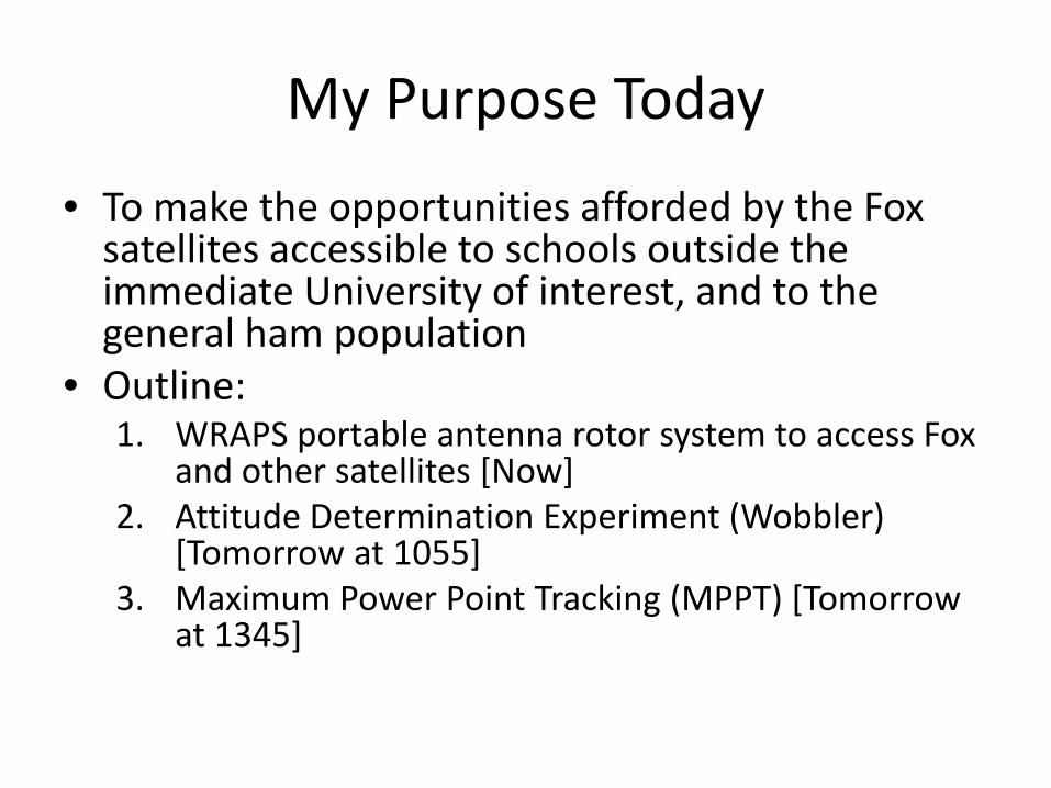
• To make the opportunities afforded by the Fox satellites accessible to schools outside the immediate University of interest, and to the general ham population
• Outline: 1. WRAPS portable antenna rotor system to access Fox
and other satellites [Now] 2. Attitude Determination Experiment (Wobbler)
[Tomorrow at 1055] 3. Maximum Power Point Tracking (MPPT) [Tomorrow
at 1345]
Wobbler, RadFx, Antenna Pointing System
WRAPS
WRAPS Design Goals
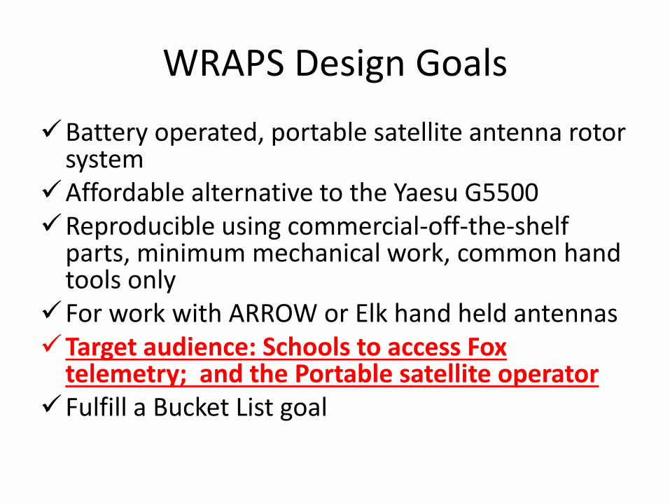
Battery operated, portable satellite antenna rotor system
Affordable alternative to the Yaesu G5500 Reproducible using commercial-off-the-shelf
parts, minimum mechanical work, common hand tools only
For work with ARROW or Elk hand held antennas Target audience: Schools to access Fox
telemetry; and the Portable satellite operator Fulfill a Bucket List goal
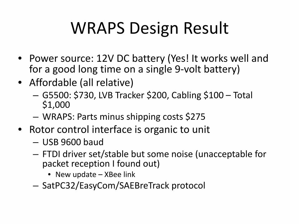
WRAPS Design Result • Power source: 12V DC battery (Yes! It works well and
for a good long time on a single 9-volt battery) • Affordable (all relative)
– G5500: $730, LVB Tracker $200, Cabling $100 – Total $1,000
– WRAPS: Parts minus shipping costs $275 • Rotor control interface is organic to unit
– USB 9600 baud – FTDI driver set/stable but some noise (unacceptable for
packet reception I found out) • New update – XBee link
– SatPC32/EasyCom/SAEBreTrack protocol
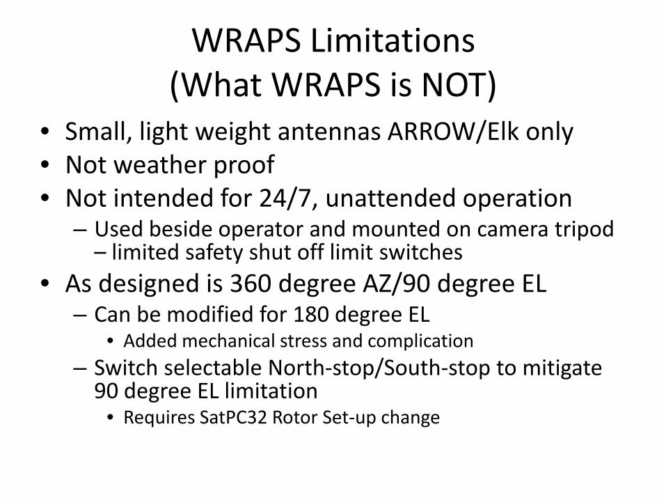
WRAPS Limitations (What WRAPS is NOT)
• Small, light weight antennas ARROW/Elk only • Not weather proof • Not intended for 24/7, unattended operation
– Used beside operator and mounted on camera tripod – limited safety shut off limit switches
• As designed is 360 degree AZ/90 degree EL – Can be modified for 180 degree EL
• Added mechanical stress and complication – Switch selectable North-stop/South-stop to mitigate
90 degree EL limitation • Requires SatPC32 Rotor Set-up change
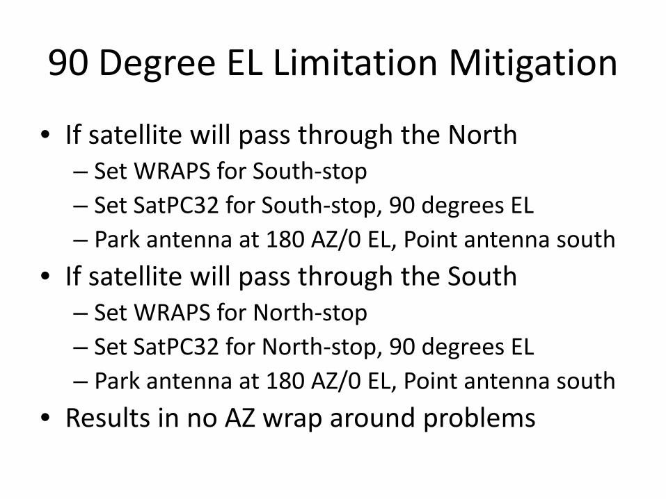
90 Degree EL Limitation Mitigation
• If satellite will pass through the North – Set WRAPS for South-stop – Set SatPC32 for South-stop, 90 degrees EL – Park antenna at 180 AZ/0 EL, Point antenna south
• If satellite will pass through the South – Set WRAPS for North-stop – Set SatPC32 for North-stop, 90 degrees EL – Park antenna at 180 AZ/0 EL, Point antenna south
• Results in no AZ wrap around problems

WRAPS Big Picture

Double Sided PCB/Position Resistor Mounts

PCB Parts Separated
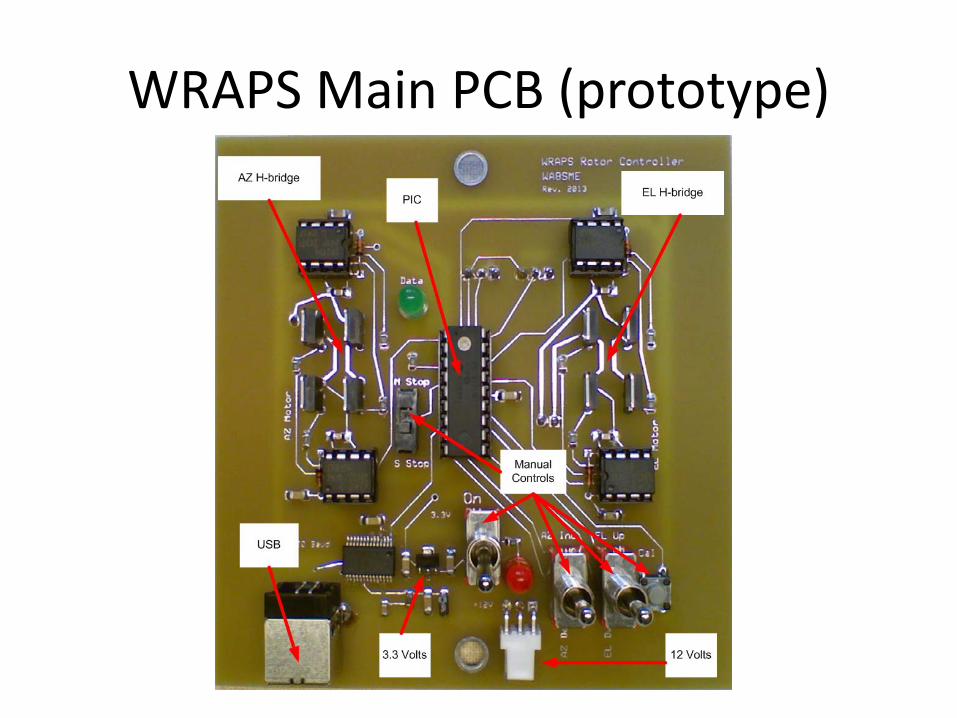
WRAPS Main PCB (prototype)
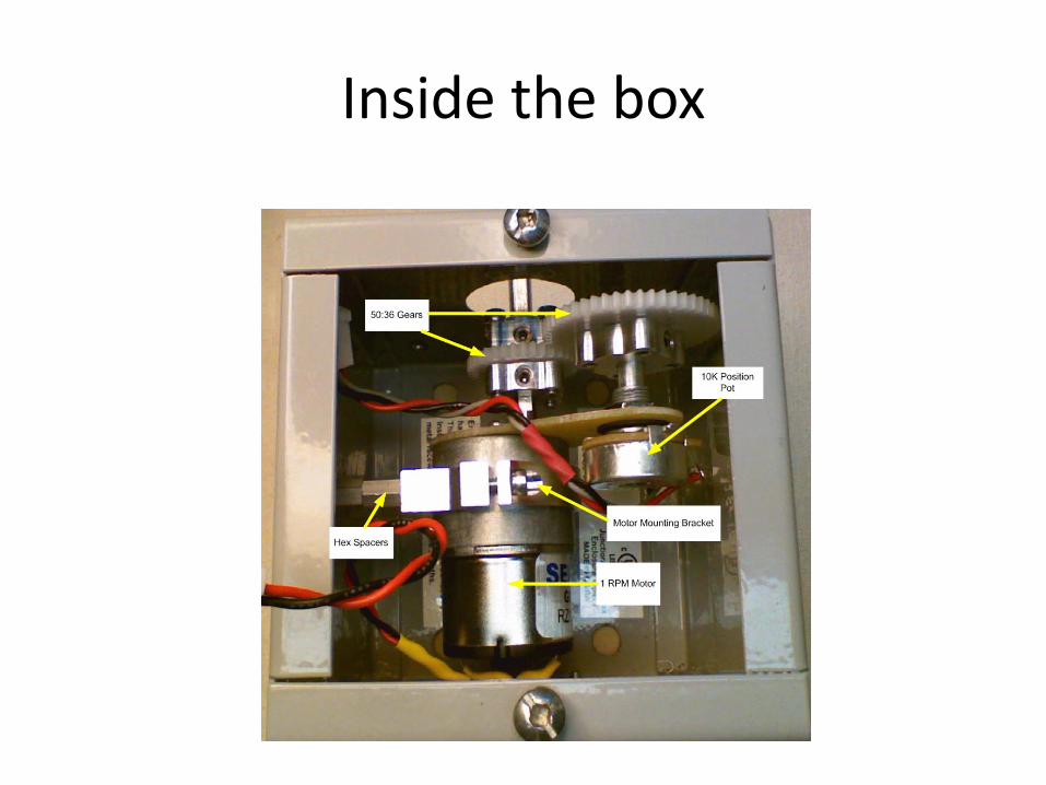
Inside the box
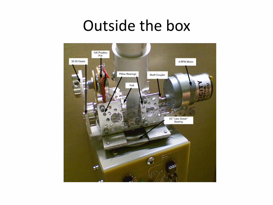
Outside the box

Simple but it works

Fox Attitude Determination Experiment (Wobbler)
The Second Increment

Attitude Determination Experiment (Wobbler)
“In addition to the communications package, Fox-1 will host an experiment payload. AMSAT is sponsoring a capstone project at Penn State University for the 2011-2012 academic year... The project will involve designing and constructing an attitude experiment based on a 3-axis, micro-electro-mechanical gyroscope. The experiment data will measure the performance of the satellite’s magnetic stabilization system...”
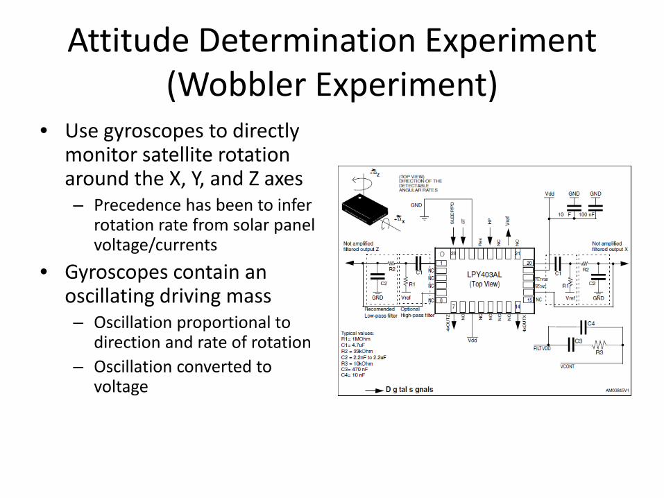
Attitude Determination Experiment (Wobbler Experiment)
• Use gyroscopes to directly monitor satellite rotation around the X, Y, and Z axes – Precedence has been to infer
rotation rate from solar panel voltage/currents
• Gyroscopes contain an oscillating driving mass – Oscillation proportional to
direction and rate of rotation – Oscillation converted to
voltage
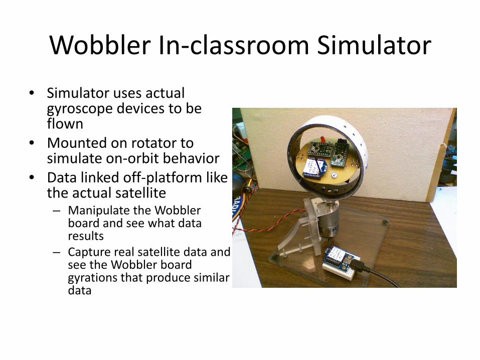
Wobbler In-classroom Simulator • Simulator uses actual
gyroscope devices to be flown
• Mounted on rotator to simulate on-orbit behavior
• Data linked off-platform like the actual satellite – Manipulate the Wobbler
board and see what data results
– Capture real satellite data and see the Wobbler board gyrations that produce similar data
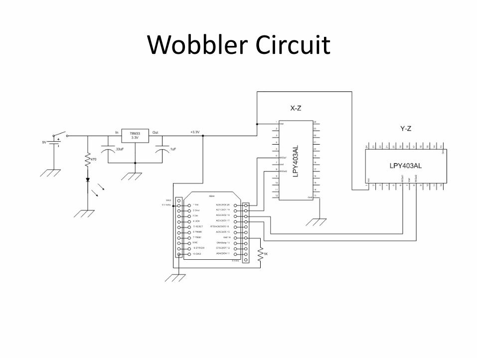
Wobbler Circuit
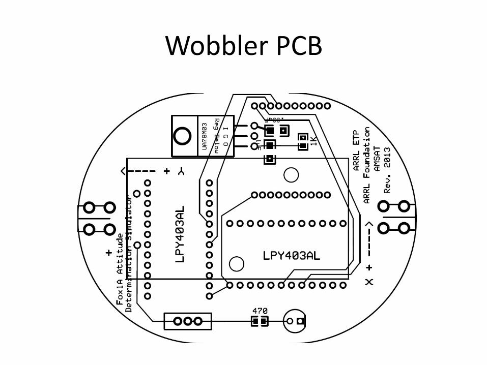
Wobbler PCB
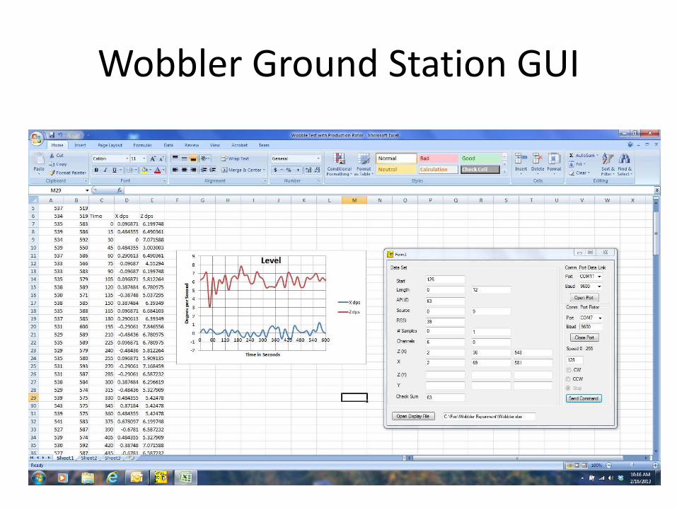
Wobbler Ground Station GUI
• GUI displays data transmitted by Wobbler board
• GUI also used to control rotator behavior (direction and rate of rotation)
• GUI dumps data to Excel for exploitation and graphing
Wobbler Ground Station GUI
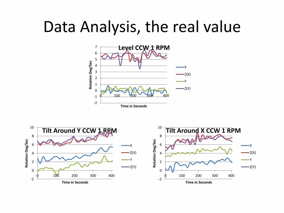
Data Analysis, the real value
-2 -1 0 1 2 3 4 5 6 7
0 100 200 300 400 Ro
tatio
n De
g/Se
c
Time in Seconds
Level CCW 1 RPM
X
Z(X)
Y
Z(Y)
-2
0
2
4
6
8
10
0 100 200 300 400
Rota
tion
Deg/
Sec
Time in Seconds
Tilt Around X CCW 1 RPM
X
Z(X)
Y
Z(Y)
-2
0
2
4
6
8
10
0 100 200 300 400
Rota
tion
Deg/
Sec
Time in Seconds
Tilt Around Y CCW 1 RPM
X
Z(X)
Y
Z(Y)
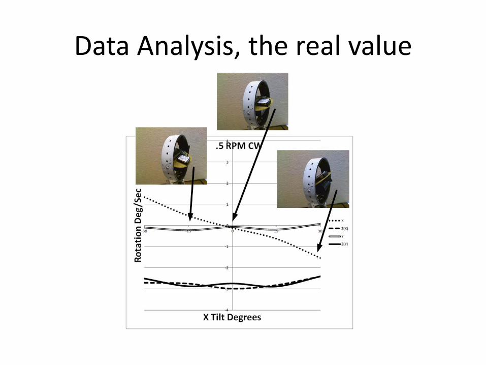
Data Analysis, the real value
Fox2 Maximum Power Point Tracking (MPPT)
Experiment
The Final Increment
MPPT Task
Rochester Institute of Technology (R.I.T.) engineering students have tackled the task of developing a maximum power point tracking (MPPT) system for use on the AMSAT Fox-2 satellite (see March/April 2013 AMSAT JOURNAL). Their task was to prototype a system that optimizes the power delivered by the satellite’s solar panels.
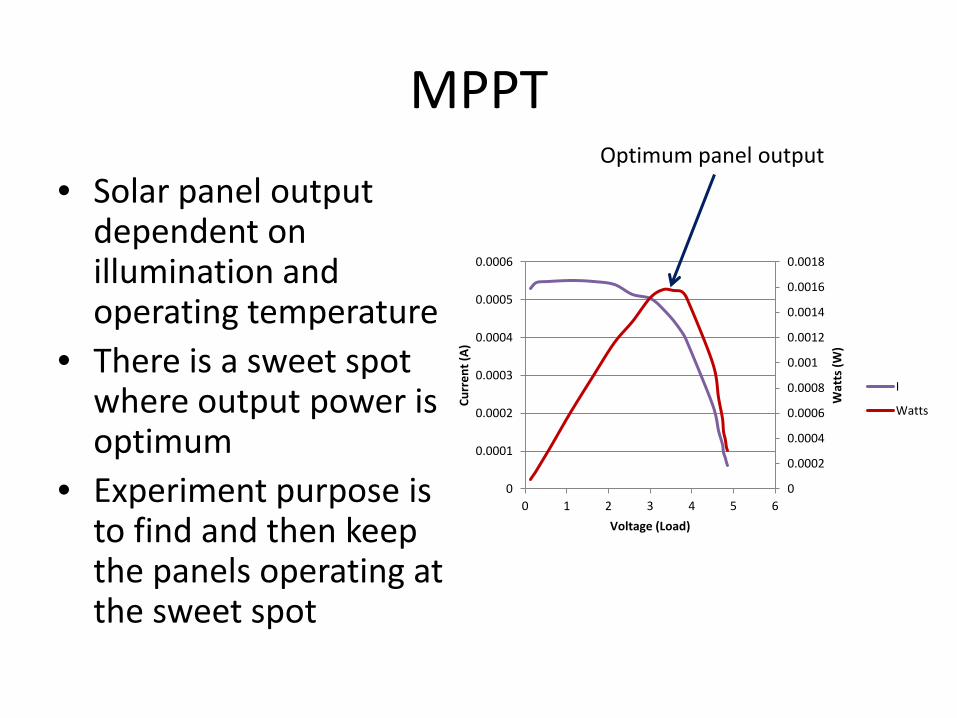
MPPT
• Solar panel output dependent on illumination and operating temperature
• There is a sweet spot where output power is optimum
• Experiment purpose is to find and then keep the panels operating at the sweet spot
0
0.0002
0.0004
0.0006
0.0008
0.001
0.0012
0.0014
0.0016
0.0018
0
0.0001
0.0002
0.0003
0.0004
0.0005
0.0006
0 1 2 3 4 5 6
Wat
ts (W
)
Curr
ent (
A)
Voltage (Load)
I
Watts
Optimum panel output
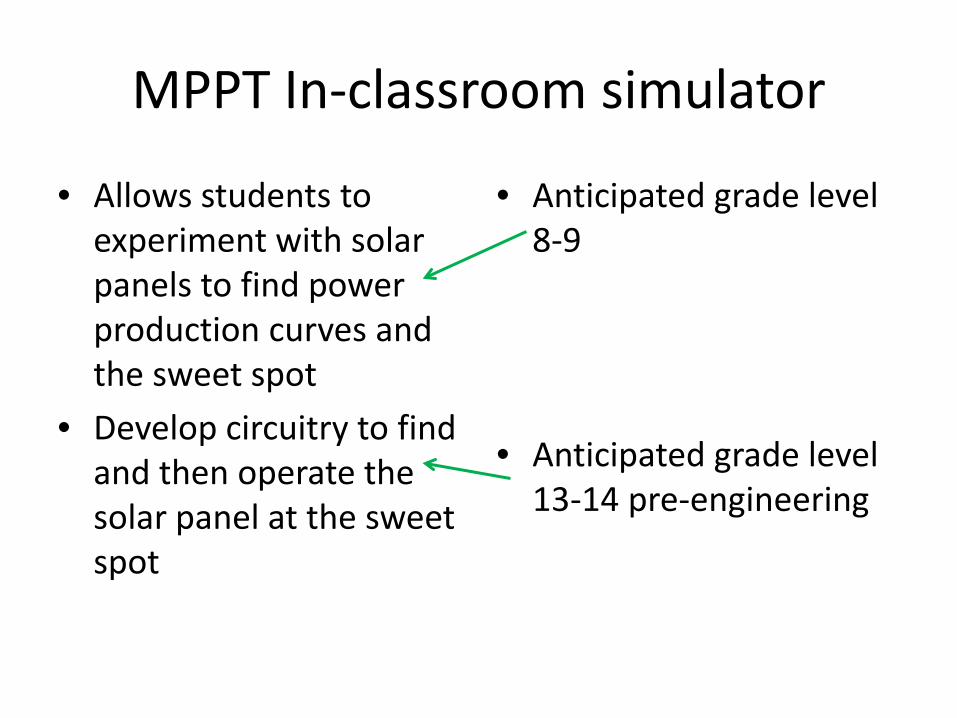
MPPT In-classroom simulator
• Allows students to experiment with solar panels to find power production curves and the sweet spot
• Develop circuitry to find and then operate the solar panel at the sweet spot
• Anticipated grade level 8-9
• Anticipated grade level 13-14 pre-engineering

Possible MPPT Circuit Block Diagram
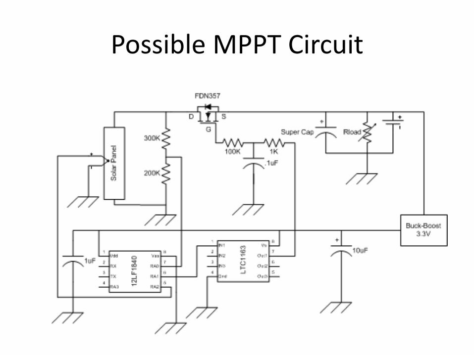
Possible MPPT Circuit
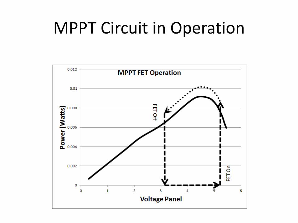
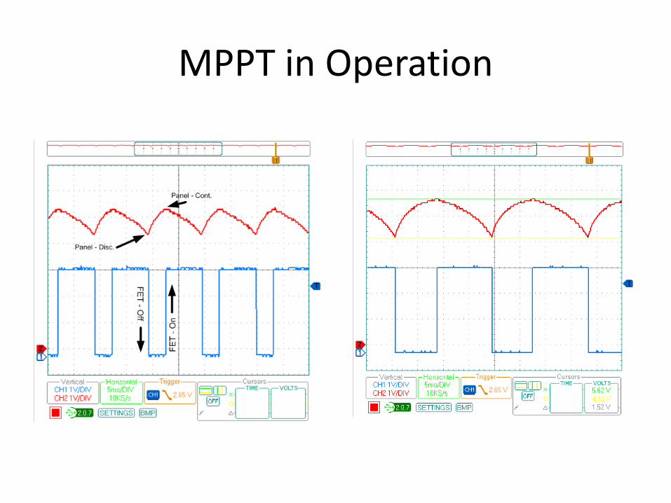
MPPT Circuit in Operation

MPPT Circuit in Operation
0
0.0002
0.0004
0.0006
0.0008
0.001
0.0012
0.0014
0.0016
0.0018
0
0.0001
0.0002
0.0003
0.0004
0.0005
0.0006
0 1 2 3 4 5 6 W
atts
(W)
Curr
ent (
A)
Voltage (Load)
I
Watts
FET control voltage
Panel operated in sweet spot
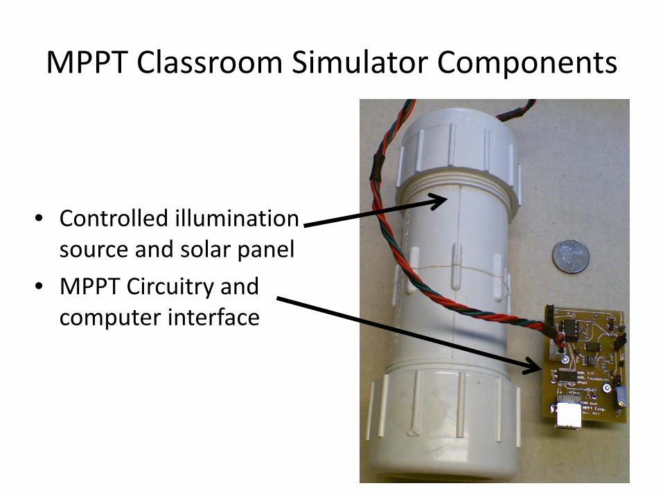
MPPT Classroom Simulator Components
• Controlled illumination source and solar panel
• MPPT Circuitry and computer interface
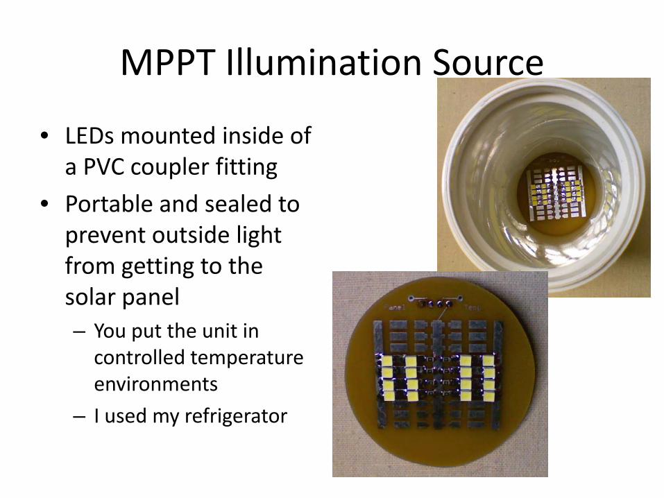
MPPT Illumination Source
• LEDs mounted inside of a PVC coupler fitting
• Portable and sealed to prevent outside light from getting to the solar panel – You put the unit in
controlled temperature environments
– I used my refrigerator
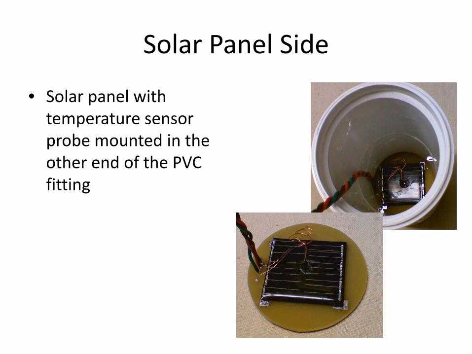
Solar Panel Side
• Solar panel with temperature sensor probe mounted in the other end of the PVC fitting
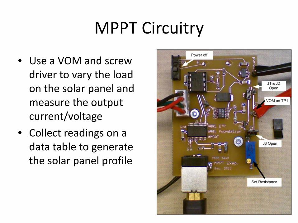
MPPT Circuitry
• Use a VOM and screw driver to vary the load on the solar panel and measure the output current/voltage
• Collect readings on a data table to generate the solar panel profile
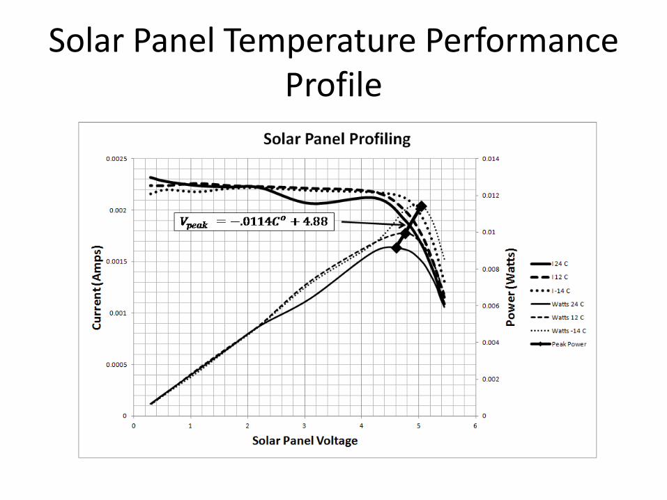
Solar Panel Temperature Performance Profile
MPPT in Operation

MPPT Simulator Circuit based on PIC
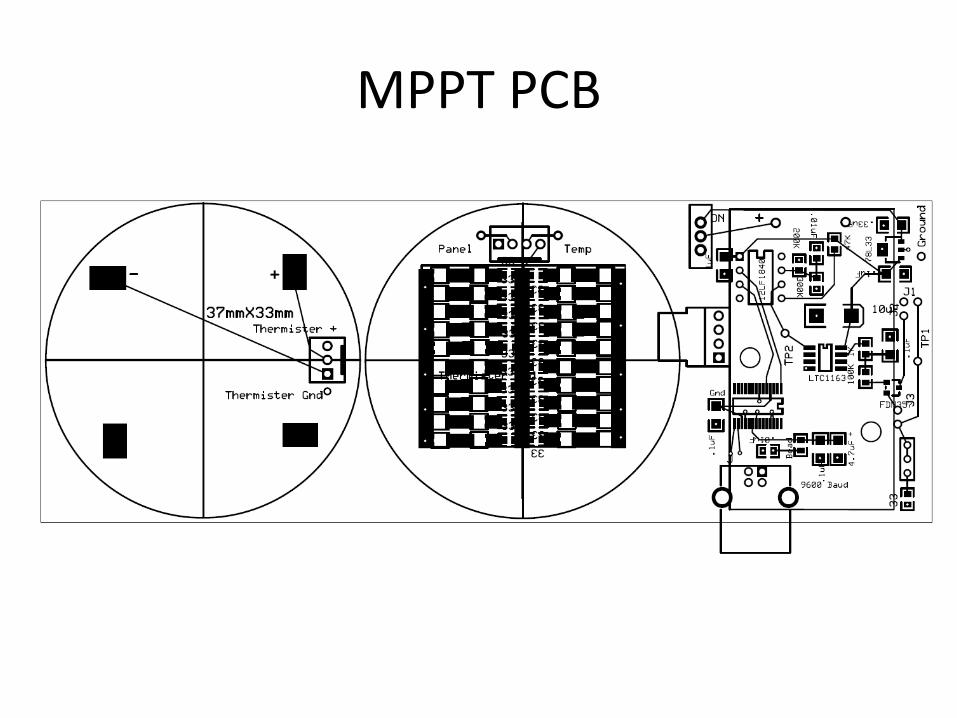
MPPT PCB
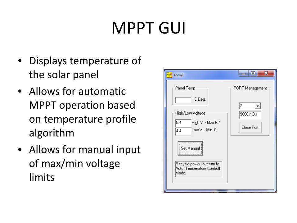
MPPT GUI
• Displays temperature of the solar panel
• Allows for automatic MPPT operation based on temperature profile algorithm
• Allows for manual input of max/min voltage limits

Conclusion
• My Purpose: to make the Fox experiments more accessible beyond the Universities, including the average ham satellite enthusiast
• I have the hardware with me for up-close show-and-tell if you are interested
• If you would like the specifics and details of any of the systems, send me a note at [email protected] and I will provide a DropBox link to the information I have on hand.

Sponsors
• The efforts I detailed yesterday and today were made possible by: – A grant from the ARRL Foundation – An award from the YASME Foundation
• My thanks to them for their support

• Questions that I can try to answer?
• If not, thanks for your attention and I will be around for one-on-one if you like.
• Mark Spencer, WA8SME [email protected] or 860-460-1139