bf5a owner’s manual - american honda motor company · 2013. 6. 18. · a honda outboard motor. we...
TRANSCRIPT

BF5AOwner’s Manual
©2002 Honda Motor Co., Ltd. -All Rights Reserved31ZV163400X31-ZV1-6340
2eY11000.2002.04Printed in JapanN
31ZV163431ZV163431ZV1634PANTONE 288 CVC DIC F101 BLACK
The engine exhaust from thisproduct contains chemicalsknown to the State of California tocause cancer, birth defects, orother reproductive harm.
The information and specifications included in this publication were in effect at thetime of approval for printing. Honda Motor Co., Ltd. reserves the right, however, todiscontinue or change specifications or design at any time without notice and withoutincurring any obligation whatever. No part of this publication may be reproducedwithout written permission.
Keep this owner’s manual handy, so you can refer to it at any time. This owner’smanual is considered a permanent part of the outboard motor and should remain withthe outboard motor if resold.
02/04/02 15:37:29 31ZV1630_001

1
INTRODUCTION
Congratulations on your selection ofa Honda outboard motor. We arecertain you will be pleased with yourpurchase of one of the finestoutboard motors on the market.
We want to help you get the bestresults from your new outboardmotor and to operate it safely. Thismanual contains the information onhow to do that; please read itcarefully.
As you read this manual you willfind information preceded by a
symbol. That informationis intended to help you avoid damageto your outboard motor, otherproperty, or the environment.
We suggest you read the warrantypolicy to fully understand itscoverage and your responsibilities ofownership. The warranty policy is aseparate document that should havebeen given to you by your dealer.
When your outboard motor needsscheduled maintenance, keep in mindthat your Honda marine dealer isspecially trained in servicing Hondaoutboard motors. Your Honda marinedealer is dedicated to yoursatisfaction and will be pleased toanswer your questions and concerns.
2002 Honda Motor Co., Ltd. AllRights Reserved
02/04/02 15:37:36 31ZV1630_002

-
-
-
-
-
-
2
A FEW WORDS ABOUTSAFETY
INTRODUCTION
Safety Messages
Safety Headings
Safety Labels
Safety Section
Instructions
IMPORTANT SAFETY INFORMATION.
OUTBOARD MOTOR SAFETY.
Your safety and the safety of othersare very important. And using thisoutboard motor safely is an importantresponsibility.
To help you make informeddecisions about safety, we haveprovided operating procedures andother information on labels and inthis manual. This information alertsyou to potential hazards that couldhurt you or others.
Of course, it is not practical orpossible to warn you about all thehazards associated with operating ormaintaining an outboard motor. Youmust use your own good judgment.
You will find important safety information in a variety of forms, including:
This entire book is filled with important safety information please read itcarefully.
preceded by a safety alert symbol and one ofthree signal words, DANGER, WARNING, or CAUTION.
These signal words mean:
such as
on the outboard motor.
such as
how to use this outboard motor correctly and safely.
You WILL be KILLED or SERIOUSLYHURT if you don’t follow instructions.
You CAN be KILLED or SERIOUSLYHURT if you don’t follow instructions.
You CAN be HURT if you don’t followinstructions.
02/04/02 15:37:49 31ZV1630_003

?
?
3
CONTENTS
...................................OUTBOARD MOTOR SAFETY . 6................IMPORTANT SAFETY INFORMATION . 6
................................SAFETY LABEL LOCATIONS . 8
....................................CONTROLS AND FEATURES . 9CONTROL AND FEATURE
..................................IDENTIFICATION CODES . 9....COMPONENT AND CONTROL LOCATIONS . 10
..............................................................CONTROLS . 12....................Engine Stop Switch and Switch Clip . 12
..........................................................Choke Knob . 12
..........................................................Throttle Grip . 13..........................................Throttle Friction Knob . 13
.....................................................Gearshift Lever . 13................................................Recoil Starter Grip . 14
.....................................Engine Cover Lock Lever . 14.............................Transom Angle Adjusting Rod . 14
............................................Steering Friction Bolt . 15...............................................................Tilt Lever . 15
.......................................................INSTRUMENTS . 15............................................................Fuel Gauge . 15
...........................................................INDICATORS . 16............................................Oil Pressure Indicator . 16
.....................................Cooling System Indicator . 16................................................OTHER FEATURES . 16
....................................................................Anode . 16................................................Portable Fuel Tank . 17
.............................................Fuel Cap Vent Knob . 17.................................................Fuel Priming Bulb . 17
..........................................................INSTALLATION . 18.....................................POWER REQUIREMENTS . 18
..................................INSTALLATION POSITION . 18.......................................................ATTACHMENT . 19
.....................TRANSOM ANGLE ADJUSTMENT . 19
................................................BEFORE OPERATION . 20.....ARE YOU READY TO GET UNDER WAY . 20
IS YOUR OUTBOARD MOTOR................................................READY TO GO . 20
02/04/02 15:37:53 31ZV1630_004
4
CONTENTS
................................................................OPERATION . 22....................SAFE OPERATING PRECAUTIONS . 22
.......................................BREAK-IN PROCEDURE . 22.....................TRANSOM ANGLE ADJUSTMENT . 22
.......................................PORTABLE FUEL TANK . 23................................FUEL HOSE CONNECTIONS . 23
.......................................................FUEL PRIMING . 24......................................STARTING THE ENGINE . 24.....................................EMERGENCY STARTING . 26
.......................................STOPPING THE ENGINE . 29................................Emergency Engine Stopping . 29
.......................................Normal Engine Stopping . 29GEARSHIFTING AND
..................................THROTTLE OPERATION . 30...............................................................STEERING . 31................................................................CRUISING . 32
........................SHALLOW WATER OPERATION . 33...............MOORING, BEACHING, LAUNCHING . 34
..............SERVICING YOUR OUTBOARD MOTOR . 35...........THE IMPORTANCE OF MAINTENANCE . 35
.....................................MAINTENANCE SAFETY . 36TOOL KIT AND EMERGENCY STARTER
.....................................................................ROPE . 37...............................MAINTENANCE SCHEDULE . 38
ENGINE COVER REMOVAL AND..................................................INSTALLATION . 40
............................................Engine Oil Level Check . 40....................................................Engine Oil Change . 41
..................................Engine Oil Recommendations . 42.....................................................Lubrication Points . 43....................................................Spark Plug Service . 44
.............................................................REFUELING . 46...............................FUEL RECOMMENDATIONS . 47
.........Fuel Pump Filter Inspection and Replacement . 47....................Portable Fuel Tank and Filter Cleaning . 49
.........................................................Fuel Tank Filter . 49.................................Recoil Starter Rope Inspection . 50
..................................................Anode Replacement . 50..............................................Propeller Replacement . 51
02/04/02 15:37:57 31ZV1630_005
5
CONTENTS
....................................................................STORAGE . 52...................................STORAGE PREPARATION . 52
..........................................Cleaning and Flushing . 52........................................................................Fuel . 54
.............................................................Engine Oil . 56...................................STORAGE PRECAUTIONS . 56
...............................REMOVAL FROM STORAGE . 57
........................................................TRANSPORTING . 58WITH OUTBOARD MOTOR INSTALLED
.............................................................ON BOAT . 58WITH OUTBOARD MOTOR REMOVED
.......................................................FROM BOAT . 58
TAKING CARE OF UNEXPECTED..........................................................PROBLEMS . 59
..................................ENGINE WILL NOT START . 59HARD STARTING OR STALLS AFTER
...........................................................STARTING . 61...........................................ENGINE OVERHEATS . 62
..ENGINE WILL NOT DRIVE THE PROPELLER . 63OIL PRESSURE INDICATOR LIGHT GOES OFF
...................AND ENGINE SPEED IS LIMITED . 64..........................................SUBMERGED MOTOR . 65
..TECHNICAL AND CONSUMER INFORMATION . 67...............................TECHNICAL INFORMATION . 67
........................................Serial Number locations . 67Carburetor Modification for High Altitude
...........................................................Operation . 68..................................................Oxygenated Fuels . 69
.................Emission Control System Information . 70..............................................................Star Label . 72
........................................................Specifications . 74...............................CONSUMER INFORMATION . 75
..................................................WIRING DIAGRAMS . 76
...........................................................................INDEX . 77
02/04/02 15:38:01 31ZV1630_006
6
IMPORTANT SAFETYINFORMATION
Operator Responsibility
OUTBOARD MOTOR SAFETY
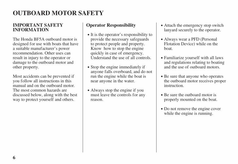
It is the operator’s responsibility toprovide the necessary safeguardsto protect people and property.Know how to stop the enginequickly in case of emergency.Understand the use of all controls.
Attach the emergency stop switchlanyard securely to the operator.
Stop the engine immediately ifanyone falls overboard, and do notrun the engine while the boat isnear anyone in the water.
Always stop the engine if youmust leave the controls for anyreason.
Always wear a PFD (PersonalFlotation Device) while on theboat.
Familiarize yourself with all lawsand regulations relating to boatingand the use of outboard motors.
Be sure that anyone who operatesthe outboard motor receives properinstruction.
Be sure the outboard motor isproperly mounted on the boat.
Do not remove the engine coverwhile the engine is running.
Most accidents can be prevented ifyou follow all instructions in thismanual and on the outboard motor.The most common hazards arediscussed below, along with the bestway to protect yourself and others.
The Honda BF5A outboard motor isdesigned for use with boats that havea suitable manufacturer’s powerrecommendation. Other uses canresult in injury to the operator ordamage to the outboard motor andother property.
02/04/02 15:38:13 31ZV1630_007
7
Carbon Monoxide HazardRefuel With Care
OUTBOARD MOTOR SAFETY
Exhaust gas contains poisonouscarbon monoxide. Avoid inhalationof exhaust gas. Never run the enginein a closed garage or confined area.
Gasoline is extremely flammable,and gasoline vapor can explode.Refuel outdoors, in a well-ventilated area, with the enginestopped. Never smoke neargasoline, and keep other flamesand sparks away.
Remove any portable fuel tankfrom the boat for refueling. Keepthe portable fuel tank away fromthe battery or other potential sparksources.
Refuel carefully to avoid spillingfuel. Avoid overfilling the fueltank.
After refueling, tighten the fillercap securely. If any fuel is spilled,make sure the area is dry beforestarting the engine.
02/04/02 15:38:21 31ZV1630_008

8
SAFETY LABEL LOCATIONS
OUTBOARD MOTOR SAFETY
The labels shown here contain important safety information. Please read them carefully. These labels are consideredpermanent parts of your outboard motor. If a label comes off or becomes hard to read, contact an authorized HondaMarine servicing dealer for a replacement.
02/04/02 15:38:34 31ZV1630_009

9
CONTROL AND FEATURE IDENTIFICATION CODES
CONTROLS AND FEATURES
Shaft Length
Type
Model
According to Shaft LengthS: Short ShaftL: Long Shaft
BF5A
Refer to this chart for an explanation of the Type Codes used in this manual to identify control and feature applications.
BF5A is provided with the following typesaccording to the shaft length.
SA
S
LA
L
DestinationA=United States
L=Long ShaftS=Short Shaft
(Example)L A
02/04/02 15:38:44 31ZV1630_010

10
COMPONENT AND CONTROL LOCATIONS
CONTROLS AND FEATURES
OIL FILLER CAP
TILT LEVER
ENGINE COVER
TILLERHANDLE
ANTIVENTILATIONPLATE
EXHAUST
ANODE
SPARK PLUG
THROTTLE GRIP
GEAR OILDRAIN PLUG
GEAR OILLEVEL PLUG
CHOKE KNOB
ENGINE STOPSWITCH
LANYARD
FUEL HOSECONNECTOR(MALE)
WATER INTAKESCREEN
TRANSOM ANGLEADJUSTING ROD
PROPELLER
GEARSHIFT LEVER
WATERCHECK HOLE
ENGINE OILDRAIN PLUG
ENGINE COVERLOCK LEVER
FLUSHING PORT
STEERINGFRICTION BOLT
STERN BRACKET
THROTTLEFRICTION KNOB
OIL PRESSUREINDICATOR LAMP
CLAMP SCREW
SWITCHCLIP
STARTER GRIP
02/04/02 15:38:57 31ZV1630_011

11
CONTROLS AND FEATURES
FUEL GAUGE VENT KNOB
FUEL TANK
FUEL HOSE
FUEL CAP
PRIMING BULB
FUEL HOSE CONNECTOR(FEMALE)
02/04/02 15:39:02 31ZV1630_012

12
CONTROLS
Engine Stop Switch and SwitchClip
Choke Knob
CONTROLS AND FEATURES
ENGINE STOPSWITCH
LANYARD
SWITCH CLIP
LANYARD
CHOKE KNOB
PUSH
The engine stop switch has controlsfor normal engine stopping andemergency engine stopping.
The switch clip must be inserted inthe engine stop switch in order forthe engine to start and run. Thelanyard should be attached to theoperator’s PFD (Personal FlotationDevice) or worn around the wrist asshown.
When used as described, the enginestop switch and lanyard system stopsthe engine if the operator falls awayfrom the controls.
A spare switch clip is supplied withthe tool kit.
The CLOSED position enriches thefuel mixture for starting a coldengine.
The choke knob opens and closes thechoke valves in the carburetors.
The OPEN position provides thecorrect fuel mixture for operationafter starting, and for restarting awarm engine.
02/04/02 15:39:18 31ZV1630_013

13
Throttle Grip Throttle Friction Knob Gearshift Lever
CONTROLS AND FEATURES
THROTTLE GRIP
R (reverse) N (neutral) F (forward)
INDEX MARK
THROTTLEFRICTION KNOB
TTOO DDEECCRREEAASSEEFFRRIICCTTIIOONN
TTOO IINNCCRREEAASSEEFFRRIICCTTIIOONN
GEARSHIFT LEVER
The gearshift lever is used to select F(forward), N (neutral), or R (reverse)gears.
The throttle grip controls enginespeed.
An index mark on the tiller armshows throttle position and is helpfulfor setting the throttle correctly whenstarting (p. ).
The engine can be started with thegearshift lever in the N (neutral)position only.
The throttle friction knob adjustsresistance to throttle grip rotation.
Turn the knob clockwise to increasefriction for holding a throttle settingwhile cruising.
Turn the knob counterclockwise todecrease friction for easy throttle griprotation.
If the gearshift lever is in the F(forward) or R (reverse) position, therecoil starter will not operate.
25
02/04/02 15:39:36 31ZV1630_014

14
Recoil Starter Grip Engine Cover Lock Lever Transom Angle Adjusting Rod
CONTROLS AND FEATURES
RECOIL STARTER GRIP
UNLOCK
TRANSOM ANGLE ADJUSTING ROD
ENGINE COVER LOCK LEVER
Pull the starter grip to operate therecoil starter for starting the enginemanually.
The recoil starter will operate onlywhen the gearshift lever (p. ) is inthe N (neutral) position, and the clipis in the engine stop switch or theemergency stop switch.
The engine cover lock lever fastensthe engine cover to the outboardmotor.
The transom angle adjusting rodlimits the tilt angle of the outboardmotor when fully lowered.
Proper adjustment prevents theoutboard motor from being trimmedtoo low (p. ).
1332
02/04/02 15:39:52 31ZV1630_015

15
Fuel Gauge
INSTRUMENTSSteering Friction Bolt Tilt Lever
CONTROLS AND FEATURES
TILT LEVER
FUEL GAUGE
STEERING FRICTION BOLTTTOO DDEECCRREEAASSEEFFRRIICCTTIIOONN
TTOO IINNCCRREEAASSEEFFRRIICCTTIIOONN
Less friction allows the outboardmotor to turn more easily. Morefriction helps to hold steady coursewhile cruising or to prevent theoutboard motor from swinging whiletrailering the boat.
The tilt lever enables the outboardmotor to be raised for shallow wateroperation, beaching, launching, ormooring.
A fuel gauge is built into the cap ofthe portable fuel tank.
To tilt, move the lever to the TILTposition, then raise the outboardmotor until the tilt mechanismengages at 30°, 45°, or 70° (p. ).
The steering friction bolt adjustssteering resistance.
33
02/04/02 15:40:12 31ZV1630_016

16
INDICATORS
Oil Pressure Indicator
Cooling System Indicator OTHER FEATURES
Anode
CONTROLS AND FEATURES
OIL PRESSURE INDICATOR LIGHT
COOLING SYSTEM INDICATOR
ANODE
When the green light is lit, oilpressure is OK.
If oil pressure becomes low, thegreen light will go off, and theengine protection system will limitengine speed.
Low oil pressure indicates that theengine oil level is low, or that there isa problem with the engine lubricationsystem.
Water should flow from the coolingsystem indicator while the engine isrunning. This shows that water iscirculating through the coolingsystem.
If water stops flowing while theengine is running, that indicates acooling system problem, such asclogged water intakes, which willcause engine overheating.
The anode is made of a sacrificialmaterial that helps to protect theoutboard motor from corrosion.
There is an anode on theantiventilation plate.
02/04/02 15:40:30 31ZV1630_017

17
Portable Fuel Tank Fuel Cap Vent Knob Fuel Priming Bulb
CONTROLS AND FEATURES
VENT KNOB
OOPPEENN
PRIMING BULB
INLET END(TANK)
CLOSEOUTLET END(MOTOR)
UP
The portable fuel tank has a capacityof US gal ( ) and has a fuelgauge built into the cap.
The cap is provided with a vent knobto seal the portable fuel tank forcarrying it to and from the boat.Open the vent knob 2 or 3 turnsbefore starting the engine (p. ).
A priming bulb is built into the fuelhose that connects the fuel tank to theoutboard motor.
Before starting the engine, hold thepriming bulb up in the direction ofthe arrow, then squeeze the primingbulb until it feels firm. This willensure that fuel is supplied to theengine (p. ).
123.2
23
24
02/04/02 15:40:41 31ZV1630_018
-
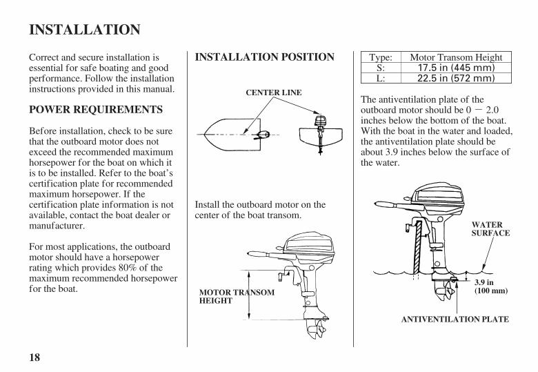
17.5 in (445 mm)22.5 in (572 mm)
18
POWER REQUIREMENTS
INSTALLATION POSITION
INSTALLATION
CENTER LINE
MMOOTTOORR TTRRAANNSSOOMMHHEEIIGGHHTT
3.9 in(100 mm)
WATERSURFACE
ANTIVENTILATION PLATE
Correct and secure installation isessential for safe boating and goodperformance. Follow the installationinstructions provided in this manual.
Before installation, check to be surethat the outboard motor does notexceed the recommended maximumhorsepower for the boat on which itis to be installed. Refer to the boat’scertification plate for recommendedmaximum horsepower. If thecertification plate information is notavailable, contact the boat dealer ormanufacturer.
For most applications, the outboardmotor should have a horsepowerrating which provides 80% of themaximum recommended horsepowerfor the boat.
Type:S:L:
Motor Transom Height
The antiventilation plate of theoutboard motor should be 0 2.0inches below the bottom of the boat.With the boat in the water and loaded,the antiventilation plate should beabout 3.9 inches below the surface ofthe water.
Install the outboard motor on thecenter of the boat transom.
02/04/02 15:40:55 31ZV1630_019
19
ATTACHMENT TRANSOM ANGLEADJUSTMENT
INSTALLATION
CLAMP SCREW
STERNBRACKET
SAFETY ROPE
If the outboard motor is installed toolow, the boat will squat and be hardto plane, it will tend to porpoise, andhigh-speed stability will be reduced.
If the outboard motor is installed toohigh, that will cause ventilation.
Optimum installation height varieswith boat type and bottom shape.Contact the boat manufacturer forany special recommendations that areunique to a specific model of boat.
If the transom needs to be modifiedto accommodate the outboard motor,contact the boat manufacturer andfollow their recommendations forcorrective action.
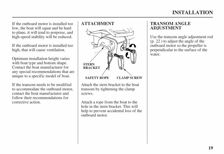
Attach the stern bracket to the boattransom by tightening the clampscrews.
Attach a rope from the boat to thehole in the stern bracket. This willhelp to prevent accidental loss of theoutboard motor.
Use the transom angle adjustment rod(p. ) to adjust the angle of theoutboard motor so the propeller isperpendicular to the surface of thewater.
22
02/04/02 15:41:08 31ZV1630_020

?
?
Improperly maintainingthis outboard motor, orfailing to correct a problembefore operation, couldcause a malfunction inwhich you could beseriously injured.
Always perform apreoperation inspectionbefore each operation, andcorrect any problem.
20
ARE YOU READY TO GETUNDER WAY
Safety
KnowledgeIS YOUR OUTBOARDMOTOR READY TO GO
BEFORE OPERATION
Your safety is your responsibility. Alittle time spent in preparation willsignificantly reduce your risk ofinjury.
Read and understand this manual.Know what the controls do and howto operate them.
Familiarize yourself with theoutboard motor and its operationbefore you get under way. Knowwhat to do in case of emergencies.
Familiarize yourself with all lawsand regulations relating to boatingand the use of outboard motors.
Always wear a PFD (PersonalFlotation Device) while on the boat.
Attach the emergency stop switchlanyard securely to your PFD or toyour wrist.
For your safety, and to maximize theservice life of your equipment, it isvery important to take a fewmoments before you operate theoutboard motor to check its condition.Be sure to take care of any problemyou find, or have your authorizedHonda Marine dealer correct it,before you operate the outboardmotor.
Before beginning your preoperationchecks, be sure the ignition switch isin the OFF position.
02/04/02 15:41:22 31ZV1630_021
21
Safety Inspection Maintenance Inspection
BEFORE OPERATION
Look around the outboard motorfor signs of oil or gasoline leaks.
If you are using the portable fueltank, make sure it is in goodcondition and properly secured inthe boat (p. ).
Check that the fuel hose isundamaged and properlyconnected (p. ).
Wipe up any spills before startingthe engine.
Check the stern bracket to be surethe outboard motor is securelyinstalled.
Check that all controls areoperating properly.
Replace any damaged parts.
Check that all fasteners are inplace and securely tightened.
Check the engine oil level (p. ).Running the engine with a low oillevel can cause engine damage.
Check to be sure the propeller isundamaged (p. ).
Check that the anode is securelyattached to the antiventilation plate(p. ) and is not excessivelyworn. The anode help to protectthe outboard motor from corrosion.
Make sure the tool kit andemergency starter rope areonboard (p. ). Replace anymissing items.
Check the fuel level in the fueltank (p. ).
23
23
40
37
51
50
46
02/04/02 15:41:35 31ZV1630_022
22
SAFE OPERATINGPRECAUTIONS
BREAK-IN PROCEDURE
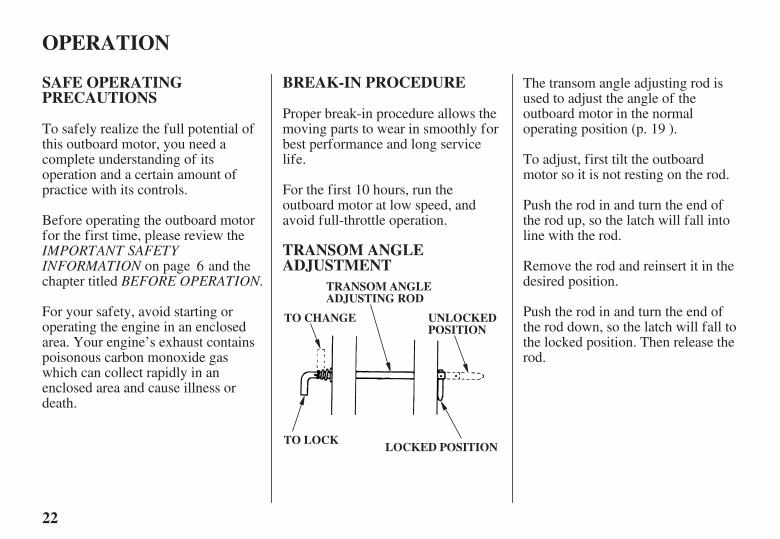
TRANSOM ANGLEADJUSTMENT
OPERATION
TRANSOM ANGLEADJUSTING ROD
TO CHANGE
TO LOCK
UNLOCKEDPOSITION
LOCKED POSITION
IMPORTANT SAFETYINFORMATION
BEFORE OPERATION.
To safely realize the full potential ofthis outboard motor, you need acomplete understanding of itsoperation and a certain amount ofpractice with its controls.
Before operating the outboard motorfor the first time, please review the
on page and thechapter titled
For your safety, avoid starting oroperating the engine in an enclosedarea. Your engine’s exhaust containspoisonous carbon monoxide gaswhich can collect rapidly in anenclosed area and cause illness ordeath.
Proper break-in procedure allows themoving parts to wear in smoothly forbest performance and long servicelife.
For the first 10 hours, run theoutboard motor at low speed, andavoid full-throttle operation.
The transom angle adjusting rod isused to adjust the angle of theoutboard motor in the normaloperating position (p. ).
To adjust, first tilt the outboardmotor so it is not resting on the rod.
Push the rod in and turn the end ofthe rod up, so the latch will fall intoline with the rod.
Remove the rod and reinsert it in thedesired position.
Push the rod in and turn the end ofthe rod down, so the latch will fall tothe locked position. Then release therod.
6
19
02/04/02 15:41:48 31ZV1630_023

Gasoline is highlyflammable and explosive.
You can be burned orseriously injured whenhandling fuel.
Wipe up spillsimmediately.
Handle fuel onlyoutdoors.
Stop the engine and keepheat, sparks, and flameaway.
23
PORTABLE FUEL TANK FUEL HOSE CONNECTIONS
OPERATION
FUEL HOSE CONNECTOR
(OUTBOARD MOTOR SIDE)
FUEL HOSE CONNECTOR
(FUEL TANK SIDE)
Place the portable fuel tank in a well-ventilated location, away from directsunlight, to reduce the possibility of agasoline vapor explosion.
To ensure that the outboard motorwill be able to draw fuel from thetank, place the tank within 6 feet ofthe outboard motor and not morethan 3 feet below the fuel connectoron the outboard motor.
Secure the portable fuel tank in theboat, so it won’t move around andbecome damaged.
Before use, open the fuel tank ventby turning the vent knob at least 2 or3 turns counterclockwise.
Connect the fuel hose to the tank andthe outboard motor, as shown. Besure both connectors snap securelyinto place.
02/04/02 15:42:02 31ZV1630_024
24
FUEL PRIMING STARTING THE ENGINE
OPERATION
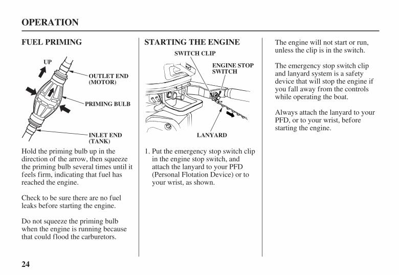
OUTLET END(MOTOR)
INLET END(TANK)
PRIMING BULB
ENGINE STOPSWITCH
LANYARD
UPSWITCH CLIP
The engine will not start or run,unless the clip is in the switch.
The emergency stop switch clipand lanyard system is a safetydevice that will stop the engine ifyou fall away from the controlswhile operating the boat.
Always attach the lanyard to yourPFD, or to your wrist, beforestarting the engine.
Hold the priming bulb up in thedirection of the arrow, then squeezethe priming bulb several times until itfeels firm, indicating that fuel hasreached the engine.
Check to be sure there are no fuelleaks before starting the engine.
Do not squeeze the priming bulbwhen the engine is running becausethat could flood the carburetors.
Put the emergency stop switch clipin the engine stop switch, andattach the lanyard to your PFD(Personal Flotation Device) or toyour wrist, as shown.
1.
02/04/02 15:42:16 31ZV1630_025

25
OPERATION
CHOKE KNOB
THROTTLE GRIP
N (neutral)
GEARSHIFT LEVER
MARK
Check the position of the gearshiftlever. It must be in the N (neutral)position for starting.
The engine will not start if thegearshift lever is in the F (forward)or R (reverse) position.
To start a cold engine, pull thechoke knob to the CLOSEDposition. To restart a warm engine,leave the choke knob in the OPENposition.
Do not turn the throttle grip beforestarting and align the STARTposition with the mark for startingthe engine.
2. 3. 4.
02/04/02 15:42:31 31ZV1630_026

26
EMERGENCY STARTING
OPERATION
STARTER GRIP
ENGINE COVER LOCK LEVER
UNLOCK
TAKING CARE OFUNEXPECTED PROBLEMS,
Pull the recoil starter grip slowlyuntil you feel resistance, then pullbriskly.
Return the starter grip gently.
If the choke knob was pulled tothe CLOSED position to start theengine, gradually push it to theOPEN position as the enginewarms up.
Also, as the engine warms up, thethrottle grip can be turned to theSLOW position without stalling.
Before getting under way, allowthe engine to warm up sufficientlyto ensure good performance.
During the warm-up period, checkthe oil pressure indicator (p. )and cooling system indicator (p.
).
If the indicators show anyabnormal condition, immediatelystop the engine and determine thecause of the problem. Refer to
p..
If the recoil starter is inoperative, youcan start the engine manually usingthe emergency starter rope suppliedwith the tool kit.
Unlock and remove the enginecover.
5.
6.
7.
16
161.
59
02/04/02 15:42:45 31ZV1630_027

-
27
OPERATION
STARTER ROPE
TAKING CARE OFUNEXPECTED PROBLEMS,
Pull the emergency starter ropeslowly until resistance is felt, thenpull briskly.
Keep away from moving partswhile pulling the rope.
If necessary, rewind the rope andpull again. If the engine does notstart after several attempts, refer to
p..
Set the controls the same as fornormal starting (see pages
). Use the choke control ifneeded.
Set the knotted end of theemergency starter rope in the notchin the flywheel. Wind the ropeclockwise around the flywheel, asshown.
4.
2. 3.24
26
59
02/04/02 15:42:55 31ZV1630_028

Exposed moving parts cancause injury.
Do not operate theoutboard motor withoutthe engine cover.
Use extreme care wheninstalling the enginecover.
28
OPERATION
If it was necessary to remove theemergency stop switch lanyardfrom your wrist to perform theemergency starting procedure, besure the lanyard is attached to yourwrist before operating theoutboard motor.
If the choke control was used tostart the engine, return the controlto the normal operating position asthe engine warms up.
Have your closest authorizedHonda marine dealer check yoursystem and correct the problem, soyou can use the recoil starter.
During the warm-up period, checkthe oil pressure indicator (p. ),and cooling system indicator (p.
).
Leave the recoil starter assemblyoff, but install the engine cover (p.
), and lock it in place bylocking the engine cover lock lever.
16
16
14
5.
6.
7.
8.
02/04/02 15:43:04 31ZV1630_029

29
STOPPING THE ENGINE
Emergency Engine Stopping
Normal Engine Stopping
OPERATION
THROTTLE GRIP
N (neutral)PULL
ENGINE STOP SWITCH
LANYARD
SWITCH CLIP
GEARSHIFT LEVER
ENGINE STOP SWITCH
PUSH
To stop the engine in an emergency,pull the clip out of the engine stopswitch by pulling the lanyard.
We suggest that you stop the enginethis way occasionally to verify thatthe engine or emergency stop switchis operating properly.
Move the throttle grip to theslowest speed and control gears toN (neutral) position.
Press the engine stop switch untilthe engine stops.
When the boat is not in use,remove and store the emergencystop switch clip and lanyard.
1.
2.
3.
02/04/02 15:43:23 31ZV1630_030

30
GEARSHIFTING ANDTHROTTLE OPERATION
OPERATION
THROTTLE GRIP
R (reverse) N (neutral) F (forward)
TTOO DDEECCRREEAASSEEFFRRIICCTTIIOONN
TTOO IINNCCRREEAASSEEFFRRIICCTTIIOONN
THROTTLEFRICTION KNOB
GEARSHIFT LEVER
To shift gears, turn the throttle grip tothe SLOW position, then move thegearshift lever to select F (forward),N (neutral) or R (reverse) gears.
The engine can be started with thegearshift lever in the N (neutral)position only.
The throttle grip can be turned to theFAST position only when thegearshift lever is in the F (forward)position.
Turn the knob counterclockwise todecrease friction for easy griprotation.
Turn the knob clockwise to increasethrottle grip friction for holding aconstant speed.
Use the throttle friction knob to helphold a constant throttle setting whilecruising.
02/04/02 15:43:37 31ZV1630_031

31
STEERING
OPERATION
STEERING FRICTION BOLT
TTOO DDEECCRREEAASSEEFFRRIICCTTIIOONN
TTOO IINNCCRREEAASSEEFFRRIICCTTIIOONN
Steer by moving the tiller handleopposite the direction you want theboat to turn.
Use the steering friction bolt to helphold a steady course while cruising.
Turn the bolt clockwise to increasesteering friction for holding a steadycourse.
Turn the bolt counterclockwise todecrease friction for easy turning.
02/04/02 15:43:51 31ZV1630_032

32
CRUISING
Engine Speed
Trim
OPERATION
Motor Angle (Cruising)
CORRECTGIVES MAXIMUM PERFORMANCE
O.K.
Excessive trim/tilt angle duringoperation can cause propellerventilation, overheating, and waterpump damage.
For rough water conditions or largewaves, slow down to prevent thepropeller from rising out of the water.
For best fuel economy, limit thethrottle opening to 80%. Use thethrottle friction control (p. ) tohelp you hold a steady speed.
Install the outboard motor at the besttrim angle for stable cruising andmaximum power.
Trim angle too large: Incorrectcauses boat to ‘‘squat’’.
Trim angle too small: Incorrectcauses boat to ‘‘plow’’.
It is necessary to trim the angle of theoutboard motor to compensate forchanges in boat load, weightdistribution, water conditions, orpropeller selection.
Under normal conditions, the boatwill perform best when theantiventilation plate is level with thewater.
When cruising into a high wind, trimthe outboard motor down slightly tolevel the boat and improve stability.With a tail wind, trim the outboardmotor up slightly.
30
02/04/02 15:44:03 31ZV1630_033

33
SHALLOW WATEROPERATION
OPERATION
30°
Do not use the tiller handle as alever to raise the outboard motor.Applying excessive f orce to the tillerhandle can damage it.
An excessive tilt angle duringoperation can cause propellerventilation, overheating, and waterpump damage.
When operating in shallow water, tiltthe outboard motor, using the tiltlever, so the propeller and gear casewon’t hit the bottom.
While the outboard motor is tilted,proceed at a low speed, and do notoperate the outboard motor in reverse.The outboard motor will risesuddenly if operated in reverse.
Monitor water flow from the coolingsystem indicator (p. ) to be surethe outboard motor is not tilted sohigh the water intake is out of thewater.
To tilt the outboard motor, move thetilt lever to the TILT position, thenraise the outboard motor to the 30°position by pulling on the enginecover grip.
16
02/04/02 15:44:12 31ZV1630_034
34
MOORING, BEACHING,LAUNCHING
OPERATION
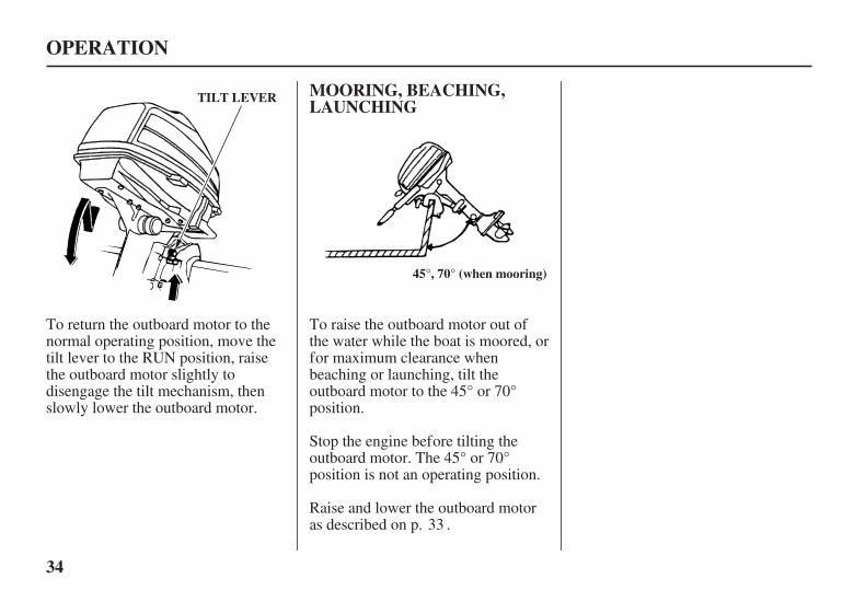
TILT LEVER
45°, 70° (when mooring)
To return the outboard motor to thenormal operating position, move thetilt lever to the RUN position, raisethe outboard motor slightly todisengage the tilt mechanism, thenslowly lower the outboard motor.
To raise the outboard motor out ofthe water while the boat is moored, orfor maximum clearance whenbeaching or launching, tilt theoutboard motor to the 45° or 70°position.
Stop the engine before tilting theoutboard motor. The 45° or 70°position is not an operating position.
Raise and lower the outboard motoras described on p. .33
02/04/02 15:44:23 31ZV1630_035
Improperly maintainingthis outboard motor, orfailure to correct a problembefore operation, can causea malfunction in which youcould be seriously hurt orkilled.
Always follow theinspection andmaintenancerecommendations andschedules in this owner’smanual.
35
THE IMPORTANCE OFMAINTENANCE
Maintenance, replacement, orrepair of the emission controldevices and systems may beperformed by any marine enginerepair establishment or individual,using parts that are ‘‘certified’’ toEPA standards.
SERVICING YOUR OUTBOARD MOTOR
Good maintenance is essential forsafe, economical, and trouble-freeoperation. It will also help reduce airpollution.
To help you properly care for youroutboard motor, the following pagesinclude a maintenance schedule,routine inspection procedures, andsimple maintenance procedures usingbasic hand tools. Other service tasksthat are more difficult, or requirespecial tools, are best handled byprofessionals and are normallyperformed by a Honda technician orother qualified mechanic.
The maintenance schedule applies tonormal operating conditions. If youoperate your outboard motor underunusual conditions, consult anauthorized Honda marine dealer forrecommendations applicable to yourindividual needs and use.
Remember that your authorizedHonda marine dealer knows youroutboard motor best and is fullyequipped to maintain and repair it.
To ensure the best quality andreliability, use only new, genuineHonda parts or their equivalents forrepair and replacement.
02/04/02 15:44:32 31ZV1630_036

-
-
-
Failure to properly followmaintenance instructionsand precautions can causeyou to be seriously hurt orkilled.
Always follow theprocedures andprecautions in the owner’smanual.
36
MAINTENANCE SAFETY Safety Precautions
Burns from hot parts.
Injury from moving parts.
Carbon monoxide poisoningfrom engine exhaust.
SERVICING YOUR OUTBOARD MOTOR
Some of the most important safetyprecautions follow. However, wecannot warn you of everyconceivable hazard that can arise inperforming maintenance. Only youcan decide whether or not you shouldperform a given task.
Make sure the engine is off beforeyou begin any maintenance orrepairs. This will eliminate severalpotential hazards:
Read the instructions before youbegin, and make sure you have thetools and skills required.
To reduce the possibility of fire orexplosion, be careful whenworking around gasoline. Use onlya nonflammable solvent, notgasoline, to clean parts. Keepcigarettes, sparks, and flames awayfrom all fuel-related parts.
Wear gloves when handling thepropeller to protect your handsfrom sharp edges.Let the engine and exhaust
system cool before touching.
Do not run the engine unlessinstructed to do so.
Be sure there is adequateventilation whenever youoperate the engine.
02/04/02 15:44:43 31ZV1630_037

×
37
TOOL KIT ANDEMERGENCY STARTERROPE
SERVICING YOUR OUTBOARD MOTOR
EMERGENCY STARTER ROPE
FLUSH KIT
10 12 mm WRENCH PLIERS
TOOL BAG
PLUG WRENCH
FLAT SCREWDRIVER
PHILIPS SCREWDRIVER
8 mm WRENCH
EMERGENCY ENGINESTOP SWITCH CLIP SPARE SPARK PLUG
HOSE CONNECTOR FOR FLUSHING
COTTER PINS
SHEAR PINS
WATER HOSE CONNECTOR
WATER MOUTH SEAT
WATER MOUTH NUT
The following tools are supplied withthe outboard motor for simplemaintenance procedures andemergency repairs. An emergencystarter rope is also supplied. Keepthese items on the boat, so they willalways be available if you need them.
02/04/02 15:44:55 31ZV1630_038

○
○○
○○
○○
○○
○○○○
○
○
○○
○
○
38
MAINTENANCE SCHEDULE
SERVICING YOUR OUTBOARD MOTOR
ITEM
REGULAR SERVICE PERIODPerform at every indicated month oroperating hour interval, whichevercomes first.
After use
Check levelChangeChangeCheckCheck-adjustCheck-adjustCheck-adjustReplaceCheckCheckCheckCheck-adjustGrease
Each useFirst month
or20 hrs.
(2)(2)
(2)(1)
Every 6 monthsor
100 hrs.
(2)
(2)(1)
Every yearor
200 hrs.
(2)
Engine oil
Gear case oilStarter ropeCarburetor linkageValve clearanceSpark plugs
Shear pinPropeller and Cotter pinAnodeIdling speedLubrication
(3)
02/04/02 15:45:04 31ZV1630_039

○○
○
○○
○
○
○
○
39
SERVICING YOUR OUTBOARD MOTOR
ITEM
Perform at every indicated month oroperating hour interval, whichevercomes first.
REGULAR SERVICE PERIODEvery year
or200 hrs.
(2)
(2)
First monthor
20 hrs.
(2)
Each use
Fuel tank and tank filterThermostatFuel filter
Fuel line
Bolts and NutsCrankcase breather tubeCooling water passages
CleanCheckCheckReplaceCheckReplaceCheck-tightnessCheckClean
After use
(4)
Every 6 monthsor
100 hrs.
(2)Every 2 years (If necessary) (2)
(3)
For professional commercial use, log hours of operation to determine proper maintenance intervals.
These items should be serviced by an authorized Honda marine dealer, unless you have the proper tools and are mechanically proficient.Refer to the Honda shop manual for service procedures.
Lubricate more frequently when used in salt water.
Emission related items.
When operating in salt water, turbid or muddy water, the engine should be flushed with clean water after each use.
(1)
(2)
(3)
(4)
02/04/02 15:45:17 31ZV1630_040
40
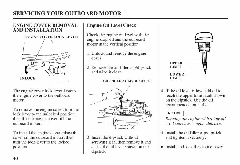
ENGINE COVER REMOVALAND INSTALLATION
Engine Oil Level Check
SERVICING YOUR OUTBOARD MOTOR
UPPERLIMIT
LOWERLIMIT
ENGINE COVER LOCK LEVER
UNLOCKOIL FILLER CAP/DIPSTICK
Running the engine with a low oillevel can cause engine damage.
Check the engine oil level with theengine stopped and the outboardmotor in the vertical position.
To install the engine cover, place thecover on the outboard motor, thenturn the lock lever to the lockedposition.
The engine cover lock lever fastensthe engine cover to the outboardmotor.
To remove the engine cover, turn thelock lever to the unlocked position,then lift the engine cover off theoutboard motor.
Unlock and remove the enginecover.
Remove the oil filler cap/dipstickand wipe it clean.
Insert the dipstick withoutscrewing it in, then remove it andcheck the oil level shown on thedipstick.
If the oil level is low, add oil toreach the upper limit mark shownon the dipstick. Use the oilrecommended on p. .
Install the oil filler cap/dipstickand tighten it securely.
Install and lock the engine cover.
1.
2.
3.
4.
5.
6.
42
02/04/02 15:45:36 31ZV1630_041

0.58 US qt (0.55 , 0.48 Impqt)
41
Engine Oil Change
SERVICING YOUR OUTBOARD MOTOR
DRAIN PLUG
Improper disposal of engine oilcan be harmf ul to the environment.If you change your own oil, pleasedispose of the used oil properly.Put it in a sealed container, andtake it to a recycling center. Donot discard it in a trash bin ordump it on the ground.
An engine oil evacuation/fillingdevice may be used to remove/addthe engine oil.
Drain the used oil while the engine iswarm. Warm oil drains quickly andcompletely.
With the outboard motor in avertical position, fill to the upperlimit mark on the dipstick (p. )with the recommended oil.
Unlock and remove the enginecover (p. ).
Allow the used oil to draincompletely, then reinstall theengine oil drain plug, and tighten itsecurely.
Remove the oil filler cap, andremove the engine oil drain plug.
Engine oil refill capacity:
Install and lock the engine cover.
Install the oil filler cap and tightenit securely.
1.
2.
3.
4.
5.
6.
40
40
02/04/02 15:45:50 31ZV1630_042

SAE Viscosity Grades
AMBIENT TEMPERATURE
42
Engine Oil Recommendations
SERVICING YOUR OUTBOARD MOTOR
Oil is a major factor affectingperformance and service life. Use4-stroke automotive detergent oil.
The SAE oil viscosity and serviceclassification are in the API label onthe oil container. Honda recommendsthat you use API SERVICE categorySF or SG oil with the ‘‘starburst’’certification mark displayed on thecontainer.
SAE 10W-30 is recommended forgeneral use. Other viscosities shownin the chart may be used when theaverage temperature in your area iswithin the recommended range.
02/04/02 15:45:56 31ZV1630_043

43
Lubrication Points
SERVICING YOUR OUTBOARD MOTOR
PROPELLER SHAFTCLAMP SCREWS
SWIVEL CASE
TILT LINKAGE
THROTTLECABLE ANDPIVOTSHIFT SHAFTAND PIVOT
TILLERHANDLE PIVOT
TILT RELEASE LEVERAND REVERSE LOCKLEVER
ENGINE COVERLOCK LEVER
Apply anticorrosion oil to pivot surf aces where greasecannot penetrate.
Apply Honda Marine Corrosion Inhibitor (or equivalent) to all areas under the engine cover except the belts.
Wipe the outside of the engine with a cloth dipped in oil.Apply marine anticorrosion grease to the following parts:lubrication, then every 20 hours or a month after the dateof purchase for initial 100 hours or 6 months.
02/04/02 15:46:19 31ZV1630_044

--
--
W16EPR-U (DENSO)BPR5ES (NGK)
W14EPR-U (DENSO)
44
Spark Plug Service
SERVICING YOUR OUTBOARD MOTOR
PLUG WRENCH0.028 0.031 in(0.70 0.80 mm)
Incorrect spark plugs can causeengine damage.
RECOMMENDED SPARK PLUGS:
Measure the spark plug electrodegap with a suitable gauge. The gapshould be 0.028 0.031 inches(0.70 0.80 mm).
Inspect the spark plug. Replacethem if the electrodes are worn, orif the insulators are cracked orchipped. Clean the spark plug witha wire brush if you are going toreuse them.
Remove the spark plug with aspark plug wrench and screwdriversupplied in the tool kit.
Disconnect the spark plug capfrom the spark plug.
Unlock and remove the enginecover (p. ).
1.
2.
3.
4. 5.
40
02/04/02 15:46:34 31ZV1630_045
45
SERVICING YOUR OUTBOARD MOTOR
Loose spark plug can overheatand damage the engine.Overtightening the spark plug candamage the threads in the cylinderhead.
Install and lock the engine cover.
If reinstalling the used spark plug,tighten 1/8 - 1/4 turn after thespark plugs seat.
If reinstalling new spark plug,tighten 1/2 turn after the sparkplugs seat.
Attach the spark plug cap.
Install the spark plug carefully, byhand, to avoid cross-threading.
After the spark plug seats, tightenwith a spark plug wrench suppliedin the tool kit to compress thesealing washer.
6. 7.
8.
9.
02/04/02 15:46:42 31ZV1630_046

3.2 US gal (12 , 2.6 Imp gal)
Gasoline is highlyflammable and explosive.
You can be burned orseriously injured whenhandling fuel.
Stop the engine and keepheat, sparks, and flameaway.Handle fuel onlyoutdoors.Wipe up spillsimmediately.
46
REFUELING
Portable Fuel Tank(optional equipment)
SERVICING YOUR OUTBOARD MOTOR
VENT KNOBCLOSE
FUEL CAP OPEN
FUEL GAUGE
SAFE FILL LEVEL
FUEL TANK CAPACITY:
To refuel, turn the vent knobcounterclockwise to the OPENposition, and unscrew the fuel tankcap.
Refuel in a well-ventilated area. Fillthe tank to the SAFE FILL LEVELline.
After refueling, install the cap andtighten it securely. Turn the ventknob clockwise to the CLOSEDposition, and return the fuel tank tothe boat.
Never refill the fuel tank inside abuilding where gasoline fumes mayreach flames or sparks. Keepgasoline away from appliance pilotlights, barbecues, electric appliances,power tools, etc.
Spilled fuel is not only a fire hazard,it causes environmental damage.Wipe up spills immediately.
Remove the fuel tank from the boatfor refueling.
Check the fuel gauge and refill thetank when necessary.
02/04/02 15:46:58 31ZV1630_047
Gasoline is highlyflammable and explosive.
You can be burned orseriously injured whenhandling fuel.
Stop the engine and keepheat, sparks, and flameaway.Handle fuel onlyoutdoors.Wipe up spillsimmediately.
47
FUEL RECOMMENDATIONS
Fuel Pump Filter Inspectionand Replacement
Use unleaded gasoline with a pumpoctane rating of 86 or higher.
SERVICING YOUR OUTBOARD MOTOR
Running the engine with persistentspark knock or pinging can causeengine damage.
Distributor’s LimitedWarranty
Your outboard motor is certified tooperate on unleaded gasoline.Unleaded gasoline produces fewerengine and spark plug deposits andextends exhaust system life.
Never use stale or contaminatedgasoline or an oil/gasoline mixture.Avoid getting dirt or water in the fueltank.
Occasionally you may hear a light‘‘spark knock’’ or ‘‘pinging’’(metallic rapping noise) whileoperating under heavy loads. This isno cause for concern.
If spark knock or pinging occurs at asteady engine speed, under normalload, change brands of gasoline. Ifspark knock or pinging persists, seean authorized Honda marine dealer.
Running the engine with persistentspark knock or pinging is misuse,and the
does not cover partsdamaged by misuse.
Water or sediment accumulated inthe filter can cause loss of power orhard starting. To prevent enginemalfunction, inspect the filter andreplace when necessary.
The fuel pump filter is located underthe engine cover, on the right side ofthe engine.
02/04/02 15:47:12 31ZV1630_048

48
SERVICING YOUR OUTBOARD MOTOR
ENGINE COVER LOCK LEVER
UNLOCK
FUEL FILTER
TUBE CLAMPS
Disconnect the fuel hose from theoutboard motor, and place clampson the fuel hoses on each side ofthe filter to prevent fuel leakagewhen the fuel hoses aredisconnected.
Unlock and remove the enginecover for access to the fuel pumpfilter.
Inspect the filter for water and/orsediment accumulation.
If the filter is OK, reinstall it. Ifwater and/or sediment are present,replace the filter as described inthe following steps. Alwaysreplace the filter at the scheduledreplacement interval (p. ).
To ease tube removal, release thetube clips by squeezing the clipends together with pliers whilepulling off the tubes.
Remove the fuel tubes from theused filter, and discard the filter.
4.
3.2.
1.
39
02/04/02 15:47:24 31ZV1630_049

49
Portable Fuel Tank and FilterCleaning
SERVICING YOUR OUTBOARD MOTOR
TANK FILTER JOINT(Fuel Connector)
FILTER
ARROW(Fuel Flow Direction) FUEL FILTER
TUBE CLAMPS
Fuel Tank
Fuel Tank Filter
Empty the portable fuel tank into anapproved gasoline container. Use afunnel to avoid spilling fuel. Rinsethe fuel tank with nonflammablesolvent to remove any accumulatedsediment.
Install the new filter on the fuelhoses, with the fuel flow arrowpointing toward the fuel pump asshown. Fuel flow will be impededif the filter is installed backward.
Remove the fuel tube clamps, andconnect the fuel hose to theoutboard motor. Check for leaks.
Install and lock the engine cover.
Unscrew the fuel hose connectorby turning it counterclockwise,then remove the fuel hoseconnector and fuel filter from thetank.
Clean the filter in nonflammablesolvent. Inspect the fuel tank filterand the connector O-ring. Replacethem if damaged.
Reinstall the filter and hoseconnector in the fuel tank. Tightenthe hose connector securely.
3.
5.
6.
7.
1.
2.
02/04/02 15:47:38 31ZV1630_050

50
Recoil Starter Rope Inspection Anode Replacement
SERVICING YOUR OUTBOARD MOTOR
RECOIL STARTER ROPE BOLT
ANODE Painting or coating the anodes willdef eat their purpose and will lead torust and corrosion damage to theoutboard motor. The anodes must beexposed to the water in order toprotect the outboard motor.
Always keep the emergency starterrope on the boat in case the recoilstarter rope fails.
Inspect the recoil starter rope, andreplace it if it becomes frayed.
The anode is located on theantiventilation plate. It is made of asacrificial material that helps toprotect the outboard motor fromcorrosion.
Replace the anode when it has beenreduced to about half its original size,or if it is crumbling.
02/04/02 15:47:49 31ZV1630_051
51
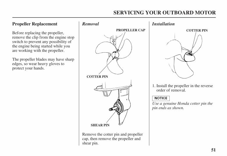
Propeller Replacement
SERVICING YOUR OUTBOARD MOTOR
COTTER PIN
PROPELLER CAP
SHEAR PIN
COTTER PIN
Removal Installation
Use a genuine Honda cotter pin thepin ends as shown.
Before replacing the propeller,remove the clip from the engine stopswitch to prevent any possibility ofthe engine being started while youare working with the propeller.
The propeller blades may have sharpedges, so wear heavy gloves toprotect your hands.
Remove the cotter pin and propellercap, then remove the propeller andshear pin.
Install the propeller in the reverseorder of removal.
1.
02/04/02 15:48:02 31ZV1630_052

52
STORAGE PREPARATION
Cleaning and Flushing
STORAGE
WATER HOSECONNECTOR
WATER HOSE
Cleaning
Flushing With the HondaGarden Hose Adapter
Proper storage preparation isessential for keeping your outboardmotor troublefree and looking good.The following steps will help to keeprust and corrosion from impairingyour outboard motor’s function andappearance, and will make the engineeasier to start when you use theoutboard motor again.
Thoroughly clean and flush theoutboard motor with fresh water afteroperation in dirty water or salt water.
Wash the outside of the outboardmotor with clean, fresh water toremove mud, salt, seaweed, etc.
Disengage the emergency enginestop switch clip from the engine stopswitch, and pull the recoil starter ropeseveral times to expel any water
remaining in the water pump.
Touch up any damaged paint, andcoat areas that may rust with HondaCorrosion Inhibitor, or equivalent.Lubricate controls with a siliconespray lubricant.
Remove the flush plug from theWASH plug hole and install thewater hose connector.
Attach a hose from a fresh waterfaucet to the water hose connectorof the flush kit.
Remove the propeller.
Turn on the fresh water supply tothe hose.
Start the engine and run in neutralfor 10 minutes.
1.
2.
3.
4.
5.
02/04/02 15:48:14 31ZV1630_053

53
STORAGE
ANTIVENTILATION PLATE
Flushing Without the HondaGarden Hose Adapter
Running the engine without goodwater circulation can causeoverheating and water pumpdamage.
Distributor’s Limited Warranty.
It is necessary to run the engineduring the flushing procedure. Forsafety, remove the propeller from theoutboard motor (p. ).
Damage caused by running theoutboard motor without sufficientcooling water is not covered by the
Start the engine and run in (N)neutral at low speed for at least 10minutes.
After flushing, stop the engine,remove the water container, andreinstall the propeller (p. ).
Place a container under theoutboard motor, and fill it withclean, fresh water. The water levelmust be at least 2 inches above theantiventilation plate.
1.
2.
3.
51
51
02/04/02 15:48:22 31ZV1630_054

Gasoline is highlyflammable and explosive.
You can be burned orseriously injured whenhandling fuel.
Wipe up spillsimmediately.
Handle fuel onlyoutdoors.
Stop the engine and keepheat, sparks, and flameaway.
54
Fuel
STORAGE
DRAIN SCREW
Distributor’s Limited Warranty
Gasoline will oxidize and deterioratein storage. Old gasoline will causehard starting, and it leaves gumdeposits that clog the fuel system. Ifthe gasoline in your fuel tank andcarburetor deteriorates during storage,you may need to have the carburetorand other fuel system componentsserviced or replaced.
The length of time that gasoline canbe left in your fuel tank andcarburetor without causing functionalproblems will vary with such factorsas gasoline blend, your storagetemperatures, and whether the fueltank is partially or completely filled.The air in a partially filled fuel tankpromotes fuel deterioration. Verywarm storage temperatures acceleratefuel deterioration. Fuel deteriorationproblems may occur within a fewmonths, or even less if the gasolinewas not fresh when you filled thefuel tank.
Thedoes not cover fuel system damageor engine performance problemsresulting from neglected storagepreparation.
You can avoid fuel deteriorationproblems by draining the fuel tankand carburetors.
Disconnect the fuel hose from theoutboard motor.
With the outboard motor in avertical position, place anapproved gasoline container belowthe fuel drain outlet, and use afunnel to avoid spilling fuel.Loosen the drain screw to drainfuel from the carburetor.
After the fuel has drained from thecarburetor, tighten the drain screwsecurely.
1.
2.
3.
02/04/02 15:48:38 31ZV1630_055

55
STORAGE
Drain the portable fuel tank into anapproved gasoline container, or Ifyou need to store fuel in the fueltank, you can extend fuel storagelife by filling the fuel tank withfresh gasoline and adding a fuelstabilizer that is formulated forthat purpose. Firmly close the fuelcap vent knob.
4.
02/04/02 15:48:42 31ZV1630_056

-
56
Engine Oil STORAGE PRECAUTIONS
STORAGE
CARRYING HANDLELif ting the outboard motor by theengine cover, or using the installedoutboard motor as a handle or leverto move the boat, can damage theoutboard motor.
Select a well-ventilated storage area.If possible, avoid storage areas withhigh humidity.
If your portable fuel tank containsgasoline, store it away from anyappliance that operates with a flame,such as a furnace, water heater, orclothes dryer. Also avoid any areawith a spark-producing electric motor,or where power tools are operated.
Change the engine oil (p. ).
To carry the outboard motor, hold itby the carrying handle, or hold by thecarrying handle and the lug beneaththe engine cover lock lever, as shown.
Remove the spark plug (p. ),and remove the clip from theengine stop switch.
Pour a tablespoon (5 10 cm ) ofclean engine oil into the cylinder.
Pull the starter rope several timesto distribute the oil in the cylinder.
Reinstall the spark plug (p. ).
1.
2.
3.
4.
5.
41
44
45
3
02/04/02 15:48:55 31ZV1630_057
57
REMOVAL FROM STORAGE
STORAGE
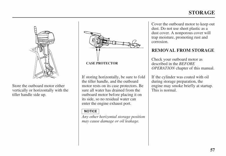
CASE PROTECTOR BEFOREOPERATION
Any other horizontal storage positionmay cause damage or oil leakage.
Cover the outboard motor to keep outdust. Do not use sheet plastic as adust cover. A nonporous cover willtrap moisture, promoting rust andcorrosion.
Check your outboard motor asdescribed in the
chapter of this manual.
If storing horizontally, be sure to foldthe tiller handle, and the outboardmotor rests on its case protectors. Besure all water has drained from theoutboard motor before placing it onits side, so no residual water canenter the engine exhaust port.
Store the outboard motor eithervertically or horizontally with thetiller handle side up.
If the cylinder was coated with oilduring storage preparation, theengine may smoke briefly at startup.This is normal.
02/04/02 15:49:06 31ZV1630_058
58
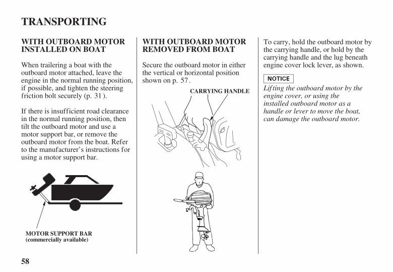
WITH OUTBOARD MOTORINSTALLED ON BOAT
WITH OUTBOARD MOTORREMOVED FROM BOAT
TRANSPORTING
CARRYING HANDLE
MOTOR SUPPORT BAR(commercially available)
Lif ting the outboard motor by theengine cover, or using theinstalled outboard motor as ahandle or lever to move the boat,can damage the outboard motor.
If there is insufficient road clearancein the normal running position, thentilt the outboard motor and use amotor support bar, or remove theoutboard motor from the boat. Referto the manufacturer’s instructions forusing a motor support bar.
Secure the outboard motor in eitherthe vertical or horizontal positionshown on p. .
To carry, hold the outboard motor bythe carrying handle, or hold by thecarrying handle and the lug beneathengine cover lock lever, as shown.When trailering a boat with the
outboard motor attached, leave theengine in the normal running position,if possible, and tighten the steeringfriction bolt securely (p. ).31
57
02/04/02 15:49:17 31ZV1630_059

59
TAKING CARE OF UNEXPECTED PROBLEMS
Check emergency stop switchclip.
Check control positions.
Clip not inserted in stop switch. Insert clip in stop switch.
Shift to neutral (p. ).
Pull choke knob to CLOSEDposition, unless engine is warm (p.
).
Turn throttle grip to STARTposition (p. ).
ENGINE WILL NOT START Possible Cause Correction
Gearshift lever not in neutralposition.
Choke OPEN.
Throttle grip not in STARTposition.
1.
2. 13
12
25
02/04/02 15:49:26 31ZV1630_060

60
TAKING CARE OF UNEXPECTED PROBLEMS
CorrectionPossible CauseENGINE WILL NOT START(continued)
Check fuel. Out of fuel.
Fuel hose not primed.
Fuel pump filter or fuel tank filterclogged.
Bad fuel; boat stored withouttreating or draining gasoline, orrefueled with bad gasoline.
Carburetor malfunction, fuel pumpfailure, ignition malfunction, stuckvalves, etc.
Refuel (p. ).
Squeeze priming bulb (p. ).
Replace fuel filters (p. ).
Replace or repair faultycomponents as necessary.
Fuel vent closed (portable fueltank).
Open fuel tank vent (p. ).
Take outboard motor to anauthorized Honda Marine dealer,or refer to the shop manual.
Remove and inspect spark plugs. Spark plug faulty, fouled orimproperly gapped.
Spark plug wet with fuel (floodedengine).
Drain fuel tank and carburetor (p.). Refill with fresh gasoline (p.).
Clean, gap or replace spark plug (p.).
Dry and reinstall spark plug. Startengine with choke and throttle open.
3.
4.
5.
17
24
46
47
5446
44
02/04/02 15:49:44 31ZV1630_061
61
TAKING CARE OF UNEXPECTED PROBLEMS
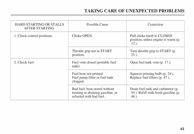
CorrectionPossible CauseHARD STARTING OR STALLSAFTER STARTING
Check control positions. Pull choke knob to CLOSEDposition, unless engine is warm (p.
).
Turn throttle grip to START (p.).
Choke OPEN.
Throttle grip not in STARTposition.
Check fuel. Fuel vent closed (portable fueltank).
Fuel hose not primed.Fuel pump filter or fuel tankclogged.
Bad fuel; boat stored withouttreating or draining gasoline, orrefueled with bad fuel.
Open fuel tank vent (p. ).
Squeeze priming bulb (p. ).Replace fuel filters (p. ).
Drain fuel tank and carburetor (p.). Refill with fresh gasoline (p.).
1.
2.
12
25
17
2447
5446
02/04/02 15:49:55 31ZV1630_062

62
TAKING CARE OF UNEXPECTED PROBLEMS
HARD STARTING OR STALLSAFTER STARTING
(continued)
Take outboard motor to anauthorized Honda Marine dealer,or refer to the shop manual.
Faulty thermostat or water pump. Replace or repair faultycomponents as necessary.
Check water intake screens. Water intake screens clogged. Clean water intake screens.
ENGINE OVERHEATS Possible Cause Correction
Carburetor malfunction, fuel pumpfailure, ignition malfunction, etc.
Replace or repair faultycomponents as necessary.
Take outboard motor to anauthorized Honda Marine dealer,or refer to the shop manual.
Possible Cause Correction
Spark plug faulty, fouled orimproperly gapped.
Clean, gap or replace spark plug (p.).
Remove and inspect spark plug.
2.
3.
4.
1.
44
02/04/02 15:50:10 31ZV1630_063

63
TAKING CARE OF UNEXPECTED PROBLEMS
ENGINE WILL NOT DRIVETHE PROPELLER
Possible Cause Correction
Check shear pin.
Take outboard motor to anauthorized Honda Marine dealer,or refer to the shop manual.
Broken shear pin.
Damaged gearshift mechanism.
Replace shear pin (p. ).
Replace or repair faultycomponents as necessary.
2.
1. 51
02/04/02 15:50:18 31ZV1630_064
64
OIL PRESSURE INDICATORLIGHT GOES OFF ANDENGINE SPEED IS LIMITED
TAKING CARE OF UNEXPECTED PROBLEMS
OIL PRESSURE INDICATOR LIGHT
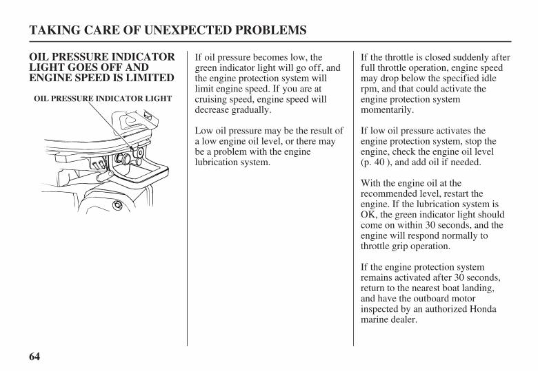
If the throttle is closed suddenly afterfull throttle operation, engine speedmay drop below the specified idlerpm, and that could activate theengine protection systemmomentarily.
If low oil pressure activates theengine protection system, stop theengine, check the engine oil level(p. ), and add oil if needed.
If oil pressure becomes low, thegreen indicator light will go off, andthe engine protection system willlimit engine speed. If you are atcruising speed, engine speed willdecrease gradually.
Low oil pressure may be the result ofa low engine oil level, or there maybe a problem with the enginelubrication system.
If the engine protection systemremains activated after 30 seconds,return to the nearest boat landing,and have the outboard motorinspected by an authorized Hondamarine dealer.
With the engine oil at therecommended level, restart theengine. If the lubrication system isOK, the green indicator light shouldcome on within 30 seconds, and theengine will respond normally tothrottle grip operation.
40
02/04/02 15:50:30 31ZV1630_065

65
SUBMERGED MOTOR
TAKING CARE OF UNEXPECTED PROBLEMS
A submerged outboard motor mustbe serviced immediately after it isrecovered from the water in order tominimize corrosion.
Remove the engine cover, andrinse the outboard motor withfresh water to remove salt water,sand, mud, etc.
If there is a Honda marine dearshipnearby, take the motor to the dealerimmediately. If you are far from adealership, proceed as follows:
Drain the carburetor as describedon p. .
Change the engine oil as describedon p. . If there was water in theengine crankcase, or if the usedengine oil showed signs of watercontamination, then a secondengine oil change should beperformed after running the enginefor half an hour.
If the engine was running when itsubmerged, there may bemechanical damage, such as a bentconnecting rod. If the engine bindswhen cranked, do not attempt torun the engine until it has beenrepaired.
Remove the spark plug (p. ),and remove the clip from theengine switch. Pull the recoilstarter grip, rotate the flywheel afew revolutions to completelyexpel any water from the cylinder.
1.
2.
3.
4.
41
54
44
02/04/02 15:50:42 31ZV1630_066

66
TAKING CARE OF UNEXPECTED PROBLEMS
When cranking the engine withan open ignition circuit (sparkplug removed f rom the ignitioncircuit), remove the clip f romthe engine stop switch toprevent possible damage to theignition system.
Attempt to start the engine.
As soon as possible, take theoutboard motor to an authorizedHonda Marine dealer forinspection and service.
If the engine starts, and nomechanical damage is evident,continue to run the engine for ahalf hour or longer. Be sure thewater level is at least two inchesabove the antiventilation plate toavoid overheating and water pumpdamage.
Pour a teaspoon of engine oil intothe spark plug hole, then pull therecoil starter grip several times tolubricate the inside of the cylinder.
Reinstall the spark plug, and putthe emergency stop switch clipinto the switch.
If the engine fails to start, removethe spark plug, clean and dry it,then reinstall the spark plug andattempt to start the engine again.
5.
6.
7.
8.
02/04/02 15:50:54 31ZV1630_067

67
TECHNICAL INFORMATION
Serial Number Locations
TECHNICAL AND CONSUMER INFORMATION
ENGINE SERIAL NUMBERPRODUCT IDENTIFICATIONNUMBER
Record the product identificationnumber and engine serial numbers inthe space provided on this page. Youwill need these numbers whenordering parts, and when makingtechnical or warranty inquiries (p.
).
The product identification number isstamped on the swibel case.
Product identification number:
The engine serial number isstamped on the right front of theengine.
Engine serial number:
75
02/04/02 15:51:07 31ZV1630_068
68
Carburetor Modification forHigh Altitude Operation
TECHNICAL AND CONSUMER INFORMATION
When the carburetor have beenmodif ied f or high altitude operation,the air-f uel mixture will be too leanf or low altitude use. Operation ataltitudes below 5,000 f eet (1,500meters) with modif ied carburetormay cause the engine to overheatand result in serious engine damage.For use at low altitudes, have anauthorized Honda Marine dealerreturn the carburetor to originalf actory specif ications.
Even with carburetor modification,engine horsepower will decreaseabout 3.5% for each 1,000-foot (300-meter) increase in altitude. The effectof altitude on horsepower will begreater than this if no carburetormodification is made.
At high altitude, the standardcarburetor air-fuel mixture will betoo rich. Performance will decrease,and fuel consumption will increase.A very rich mixture will also foul thespark plug and cause hard starting.
High altitude performance can beimproved by specific modificationsto the carburetor. If you alwaysoperate your outboard motor ataltitudes above 5,000 feet (1,500meters), have an authorized Hondamarine dealer perform this carburetormodification.
02/04/02 15:51:13 31ZV1630_069

69
Oxygenated Fuels
ETHANOL:
MTBE:
METHANOL:
TECHNICAL AND CONSUMER INFORMATION
Some conventional gasolines arebeing blended with alcohol or anether compound. These gasolines arecollectively referred to as oxygenatedfuels. To meet clean air standards,some areas of the United States andCanada use oxygenated fuels to helpreduce emissions.
If you use an oxygenated fuel, besure it is unleaded and meets theminimum octane rating requirement.
Before using an oxygenated fuel, tryto confirm the fuel’s contents. Somestates/provinces require thisinformation to be posted on the pump.
The following are the EPA-approvedpercentages of oxygenates:
ethyl or grain alcohol;10% by volume.
You may use gasoline containing upto 10% ethanol by volume. Gasolinecontaining ethanol may be marketedunder the name ‘‘Gasohol’’.
Methyl Tertiary Butyl Ether;15% by volume.
You may use gasoline containing upto 15% MTBE by volume.
methyl or woodalcohol; 5% by volume.
You may use gasoline containing upto 5% methanol by volume, as longas it also contains cosolvents andcorrosion inhibitors to protect thefuel system. Gasoline containingmore than 5% methanol by volumemay cause starting and/orperformance problems. It may also
damage metal, rubber, and plasticparts of your fuel system.
If you notice any undesirableoperating symptoms, try anotherservice station, or switch to anotherbrand of gasoline.
Fuel system damage or performanceproblems resulting from the use of anoxygenated fuel containing morethan the percentages of oxygenatesmentioned above are not coveredunder warranty.
02/04/02 15:51:24 31ZV1630_070

70
Emission Control SystemInformation
TECHNICAL AND CONSUMER INFORMATION
Source of Emissions
Tampering and AlteringThe U.S. and Calif ornia CleanAir Acts
The combustion process producescarbon monoxide, oxides of nitrogen,and hydrocarbons. Control ofhydrocarbons and oxides of nitrogenis very important because, undercertain conditions, they react to formphotochemical smog when subjectedto sunlight. Carbon monoxide doesnot react in the same way, but it istoxic.
Honda utilizes lean carburetorsettings and other systems to reducethe emissions of carbon monoxide,oxides of nitrogen, and hydrocarbons.
Tampering with or altering theemission control system may increaseemissions beyond the legal limit.Among those acts that constitutetampering are:
Removal or alteration of any partof the intake, fuel, or exhaustsystems.
Alterations that would cause theengine to operate outside its designparameters.
EPA and California regulationsrequire all manufacturers to furnishwritten instructions describing theoperation and maintenance ofemission control systems.
The following instructions andprocedures must be followed in orderto keep the emissions from yourHonda engine within the emissionstandards.
02/04/02 15:51:34 31ZV1630_071

71
TECHNICAL AND CONSUMER INFORMATION
Maintenance
Replacement PartsProblems That May Af f ectEmissions
A manufacturer of an aftermarketpart assumes the responsibility thatthe part will not adversely affectemission performance. Themanufacturer or rebuilder of the partmust certify that use of the part willnot result in a failure of the engine tocomply with emission regulations.
Follow the maintenance schedule onp. . Remember that this scheduleis based on the assumption that yourmachine will be used for its designedpurpose. Sustained high-loadoperation, or use in unusualconditions, will require morefrequent service.
If you are aware of any of thefollowing symptoms, have yourengine inspected and repaired byyour servicing dealer.
Hard starting or stalling afterstarting.
Rough idle.
Misfiring or backfiring under load.
Afterburning (backfiring).
Black exhaust smoke or high fuelconsumption.
The emission control systems onyour Honda engine were designed,built, and certified to conform withEPA and California emissionregulations. We recommend the useof genuine Honda parts wheneveryou have maintenance done. Theseoriginal-design replacement parts aremanufactured to the same standardsas the original parts, so you can beconfident of their performance. Theuse of replacement parts that are notof the original design and qualitymay impair the effectiveness of youremission control system.
38
02/04/02 15:51:45 31ZV1630_072

72
Star Label
The Symbol for Cleaner Marine Engines:
Cleaner Air and Water -
Better Fuel Economy -
Longer Emission Warranty -
TECHNICAL AND CONSUMER INFORMATION
The Star Label means Cleaner Marine Engine
A Star label was applied to thisoutboard motor in accordance withthe requirements of the CaliforniaAir Resources Board.
for healthier lifestyle and environment.
burns up to 30 - 40 percent less gas and oil thanconventional carbureted two-stroke engines, saving money and resources.
protects consumer for worry free operation.
This engine has been certified as a:
02/04/02 15:51:56 31ZV1630_073

73
One StarLow Emission
Two StarsVery Low Emission
Three StarsUltra Low Emission
TECHNICAL AND CONSUMER INFORMATION
The one-star label identifies enginesthat meet the Air Resources Board’s2001 exhaust emission standards.Engines meeting these standardshave 75% lower emissions thanconventional carbureted two-strokeengines. These engines are equivalentto the U.S. EPA’s 2006 standards formarine engines.
The two-star label identifies enginesthat meet the Air Resources Board’s2004 exhaust emission standards.Engines meeting these standardshave 20% lower emissions than OneStar-Low-Emission engines.
The three-star label identifies enginesthat meet the Air Resources Board’s2008 exhaust emission standards.Engines meeting these standardshave 65% lower emissions than OneStar-Low-Emission engines.
Cleaner Watercraft - Get the Facts1-800-END-SMOG
www.arb.ca.gov
02/04/02 15:52:05 31ZV1630_074

-
- -×
× ×
--±
±±
BF5ABADS
12.4 in (315 mm)
LASA20.7 in (525 mm)
39.8 in (1,010 mm) 45.7 in (1,160 mm)17.5 in (445 mm) 22.5 in (572 mm)59.5 lbs (27.0 kg) 60.6 lbs (27.5 kg)
3.7 kW (5.0 HP)4,000 5,000 rpm
4 stroke OHV 1 cylinder, water-cooled7.7 cu-in (127 cm )
0.028 0.031 in (0.70 0.80 mm)Recoil starter
Transisterized magnetoTrochoid pump pressure lubrication
API standard (SF or SG)SAE 10W-30
API standard (GL 4/5)SAE 90 outboard motor gear oil
0.1 US qt (0.1 , 0.1 Imp qt)0.58 US qt (0.55 , 0.48 Imp qt)
VERY LOW EMISSIONWater cooling with thermostat
Underwater exhaust
BPR5ES (NGK)W16EPR-U (DENSO)W14EPR-U (DENSO)
Diaphragm type fuel pumpAutomotive unleaded gasoline
(86 pump octane or higher)3.2 US gal (12 , 2.6 Imp gal)
Forward-Neutral-Reverse (dog type)45° right and left
5 stages (5°-9°-13°-17°-21°)3 stages adjustment (30°, 45° and 70°)7-25/32 7-31/64 in (3-200 190 mm)
0.028 0.031 in(0.70 0.80 mm)1,100 50 rpm
No other adjustment is needed
0.10 0.04 mm0.15 0.04 mm
See page 44
See shopmanual
See shopmanual
Gear case:
Engine:
Engine:Gear case: Exhaust:
Intake:
74
Specifications
TECHNICAL AND CONSUMER INFORMATION
Tune Up
MODELDescription CodeTypeOverall lengthOverall widthOverall heightTransom heightWeightRated powerFull throttle rangeEngine typeDisplacementSpark plug gapStarter systemIgnition systemLubrication systemSpecified oil
Oil capacity
CARB star labelCooling systemExhaust system
Spark plugs
Fuel pumpFuel
Tank capacityGear changeSteering angleTransom angleTilt angleStandard propeller(No. of blades-diameter pitch)
Spark plug gap
Idle speed
Valve clearance(cold)Other specifications
Honda outboards are power rated in accordance with NMMA procedures and using the ICOMIA standard 28/23.
02/04/02 15:52:42 31ZV1630_075
75
CONSUMER INFORMATION
Honda Publications
Customer Service Information
American Honda Motor Co., Inc.
TECHNICAL AND CONSUMER INFORMATION
Shop Manual
Parts Catalog
Honda Marine dealership personnelare trained professionals. Theyshould be able to answer anyquestion you may have. If youencounter a problem that your dealerdoes not solve to your satisfaction,please discuss it with the dealership’smanagement. The Service Manageror General Manager can help. Almostall problems are solved in this way.
If you are dissatisfied with thedecision made by the dealership’smanagement, contact the HondaMarine Customer Relations Office.You can write:
Marine DivisionCustomer Relations Office4900 Marconi DriveAlpharetta, Georgia 30005-8847
Or telephone: (770) 497-6400
When you write or call, please giveus this information:
Model and serial numbers (p. )
Name of the dealer who sold theoutboard motor to you
Name and address of the dealerwho services your outboard motor
Date of purchase
Your name, address, and telephonenumber
A detailed description of theproblem
These publications will give youadditional information formaintaining and repairing youroutboard motor. You may order themfrom your Honda marine dealer.
This manual covers completemaintenance and overhaul procedures.It is intended to be used by a skilledtechnician.
This manual provides complete,illustrated parts lists.
67
02/04/02 15:52:57 31ZV1630_076
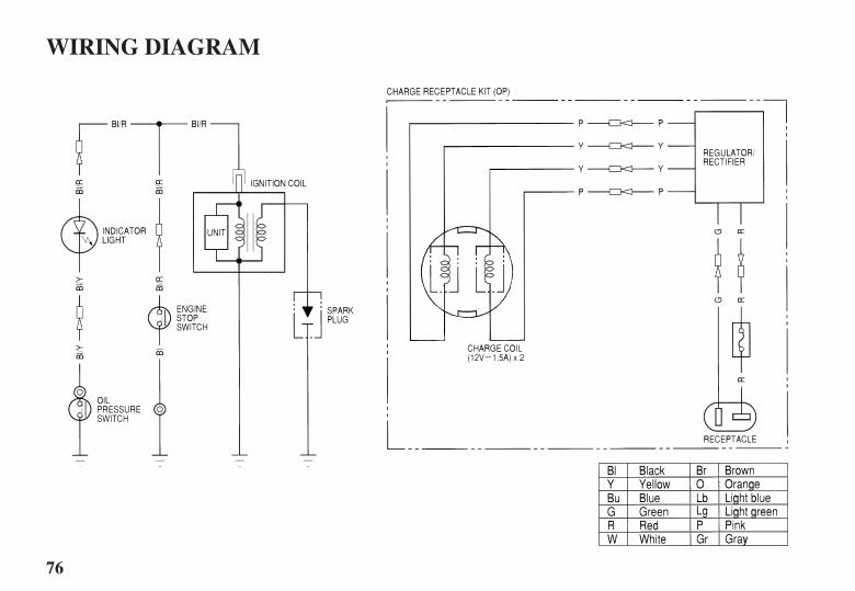
76
WIRING DIAGRAM
02/04/02 15:53:04 31ZV1630_077
?
77
INDEX
............................................................................Anode . 16..............................................................Replacement . 50
.........ARE YOU READY TO GET UNDER WAY . 20...........................................................ATTACHMENT . 19
................................................BEFORE OPERATION . 20...........................................BREAK-IN PROCEDURE . 22
.Carburetor Modification for High Altitude Operation . 68...................................................................Choke Knob . 12
........COMPONENT AND CONTROL LOCATIONS . 10...................................CONSUMER INFORMATION . 75
..................................................................CONTROLS . 12CONTROLS AND FEATURE IDENTIFICATION
........................................................................CODES . 9....................................CONTROLS AND FEATURES . 9
..............................................Cooling System Indicator . 16....................................................................CRUISING . 32
......................................Customer Service Information . 75
.........................................EMERGENCY STARTING . 26.........................Emission Control System Information . 70
EngineCover
............................................................Lock Lever . 14...................REMOVAL AND INSTALLATION . 40
Oil...................................................................Change . 41
..........................................................Level Check . 40.................................................Recommendations . 42
............................................ENGINE OVERHEARTS . 62............................Engine Stop Switch and Switch Clip . 12
......ENGINE WILL NOT DRIVE THE PROPELLER . 63......................................ENGINE WILL NOT START . 59
Fuel..........................................................Cap Vent Knob . 17
.........................................................................Gauge . 15...........................................HOSE CONNECTIONS . 23
..................................................................PRIMING . 24.............................................................Priming Bulb . 17
.................Pump Filter Inspection and Replacement . 47..........................................RECOMMENDATIONS . 47
.................................................................Tank Filter . 49
02/04/02 15:53:08 31ZV1630_078

?
78
INDEX
..GEARSHIFTING AND THROTTLE OPERATION . 30..............................................................Gearshift Lever . 13
HARD STARTING OR STALLS AFTER...............................................................STARTING . 61
....................IMPORTANT SAFETY INFORMATION . 6...........................................................................INDEX . 77
.......................................................................Indicators . 16..........................................................INSTALLATION . 18
......................................INSTALLATION POSITION . 18....................................................................Instruments . 15
IS YOUR OUTBOARD MOTOR....................................................READY TO GO . 20
.........................................................Lubrication Points . 43
.........................................MAINTENANCE SAFETY . 36...................................MAINTENANCE SCHEDULE . 38
...................MOORING, BEACHING, LAUNCHING . 34
....................................................Oil Pressure Indicator . 16OIL PRESSURE INDICATOR LIGHT GOES
..............OFF AND ENGINE SPEED IS LIMITED . 64................................................................OPERATION . 22
....................................................OTHER FEATURES . 16...................................OUTBOARD MOTOR SAFETY . 6
..........................................................Oxygenated Fuels . 69
..................................................Portable Fuel Tank . 17, 23........................Portable Fuel Tank and Filter Cleaning . 49
.........................................POWER REQUIREMENTS . 18..................................................Propeller Replacement . 51
.........................................................Recoil Starter Grip . 14......................................Recoil Starter Rope Inspection . 50
.................................................................REFUELING . 46...................................REMOVAL FROM STORAGE . 57
02/04/02 15:53:12 31ZV1630_079
79
INDEX
........................SAFE OPERATING PRECAUTIONS . 22....................................SAFETY LABEL LOCATIONS . 8
...............................................Serial Number Locations . 67..............SERVICING YOUR OUTBOARD MOTOR . 35
............................SHALLOW WATER OPERATION . 33........................................................Spark Plug Service . 44
................................................................Specifications . 74......................................................................Star Label . 72
..........................................STARTING THE ENGINE . 24....................................................................STEERING . 31
....................................................Steering Friction Bolt . 15...........................................STOPPING THE ENGINE . 29
.....................................Emergency Engine Stopping . 29...........................................Normal Engine Stopping . 29
....................................................................STORAGE . 52........................................STORAGE PRECAUTIONS . 56........................................STORAGE PREPARATION . 52
..............................................Cleaning and Flushing . 52..................................................................Engine oil . 56
............................................................................Fuel . 54...............................................SUBMERGED MOTOR . 65
....TAKING CARE OF UNEXPECTED PROBLEMS . 59..TECHNICAL AND CONSUMER INFORMATION . 67
...................................TECHNICAL INFORMATION . 67...............THE IMPORTANCE OF MAINTENANCE . 35
..................................................Throttle Friction Knob . 13..................................................................Throttle Grip . 13
.......................................................................Tilt Lever . 15..TOOL KIT AND EMERGENCY STARTER ROPE . 37
.....................................Transom Angle Adjusting Rod . 14.........................TRANSOM ANGLE ADJUSTMENT . 19
........................................................TRANSPORTING . 58WITH OUTBOARD MOTOR INSTALLED
.............................................................ON BOAT . 58WITH OUTBOARD MOTOR REMOVED
.......................................................FROM BOAT . 58
..................................................WIRING DIAGRAMS . 76
02/04/02 15:53:16 31ZV1630_080

BF5AOwner’s Manual
©2002 Honda Motor Co., Ltd. -All Rights Reserved31ZV163400X31-ZV1-6340
2eY11000.2002.04Printed in JapanN
31ZV163431ZV163431ZV1634PANTONE 288 CVC DIC F101 BLACK