bfk 470 spring-applied brake - fcr motionfcrmotion.com.au/wp-content/uploads/2014/11/intorq... ·...
TRANSCRIPT

www.intorq.com
setting the standard
BFK 470 spring-applied brakeThe IP66 modular system
2 – 370 Nm

The INTORQ brand stands for reliable brake solutions with the highest product standards. INTORQ products are used in a very diverse range of applications, from brake motors and industrial trucks to hoists, cranes and wind turbines. We can create the right solution for you and your drive – individually and reliably.
The INTORQ module system offers numerous variants that can be used in many motors and geared motors, setting standards worldwide. We have been increasing our international presence step by step, establishing sites in Shanghai, Atlanta and Pune. So our network of sales and service staff is close at hand all over the world, ready to support you.
We set the standards
INTORQ at a glance
❙ Electromagnetic brakes and clutches ❙ Flexibility with standard options as well as
customised solutions❙ Centralised product development and
production located in aerzen❙ Fast response and delivery times globally
thanks to production and warehousing in Shanghai, Atlanta and Pune.
❙ Over 50 million euros a year sales volume❙ 800,000 units a year ❙ 13,000 square metres production area❙ 250 employees❙ Market leader with 63 sales partners in 49
countries
INTORQ I Spring-applied brake BFK470
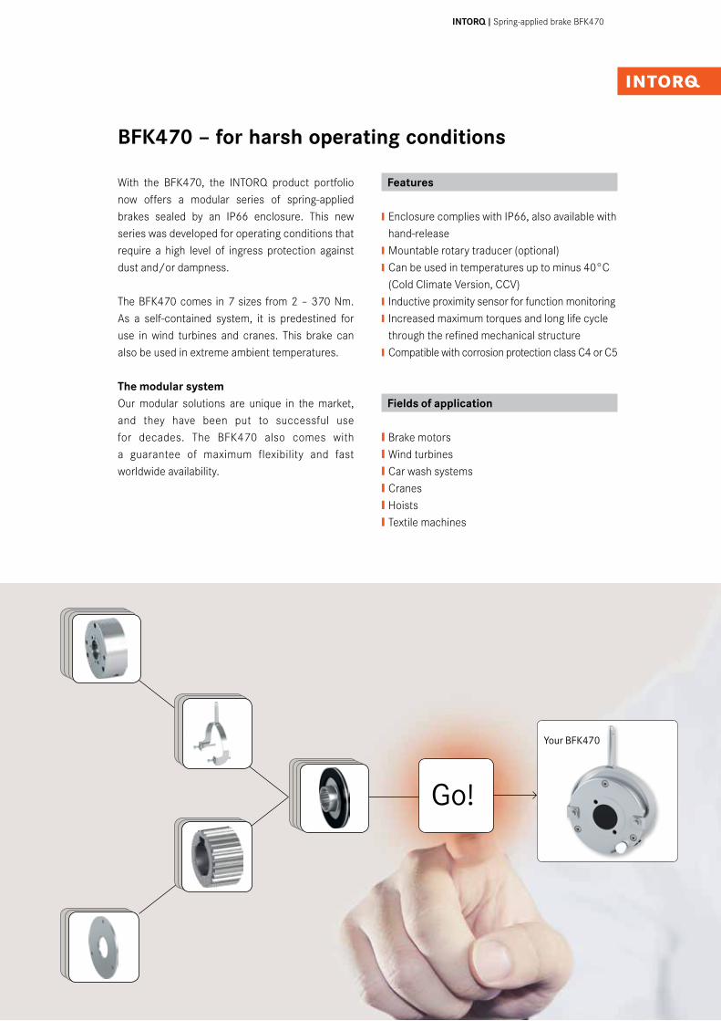
With the BFK470, the INTORQ product portfolio now offers a modular series of spring-applied brakes sealed by an IP66 enclosure. This new series was developed for operating conditions that require a high level of ingress protection against dust and/or dampness.
The BFK470 comes in 7 sizes from 2 – 370 Nm. As a self-contained system, it is predestined for use in wind turbines and cranes. This brake can also be used in extreme ambient temperatures.
The modular systemOur modular solutions are unique in the market, and they have been put to successful use for decades. The BFK470 also comes with a guarantee of maximum flexibility and fast worldwide availability.
Features
❙ Enclosure complies with IP66, also available with hand-release ❙ Mountable rotary traducer (optional)❙ Can be used in temperatures up to minus 40°C (Cold Climate Version, CCV)❙ Inductive proximity sensor for function monitoring ❙ Increased maximum torques and long life cycle through the refined mechanical structure❙ Compatible with corrosion protection class C4 or C5
Fields of application
❙Brake motors ❙Wind turbines ❙Car wash systems ❙Cranes❙Hoists ❙Textile machines
BFK470 – for harsh operating conditions
Go!
Your BFK470
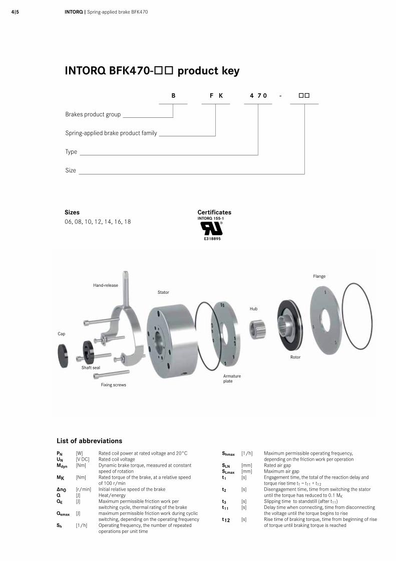
Fixing screws
Cap
Stator
Hub
Rotor
Flange
Hand-release
4I5 INTORQ I Spring-applied brake BFK470
Sizes06, 08, 10, 12, 14, 16, 18
CertificatesINTORQ 155-1
E318895
Armature plate
List of abbreviations
PN [W] Rated coil power at rated voltage and 20°CUN [V DC] Rated coil voltageMdyn [Nm] Dynamic brake torque, measured at constant speed of rotationMK [Nm] Rated torque of the brake, at a relative speed of 100 r/min∆n0 [r/min] Initial relative speed of the brakeQ [J] Heat/energyQE [J] Maximum permissible friction work per switching cycle, thermal rating of the brakeQsmax [J] maximum permissible friction work during cyclic switching, depending on the operating frequencySh [1/h] Operating frequency, the number of repeated operations per unit time
Shmax [1/h] Maximum permissible operating frequency, depending on the friction work per operationSLN [mm] Rated air gapSLmax [mm] Maximum air gapt1 [s] Engagement time, the total of the reaction delay and torque rise time t1 = t11 + t12t2 [s] Disengagement time, time from switching the stator until the torque has reduced to 0.1 MKt3 [s] Slipping time to standstill (after t11)t11 [s] Delay time when connecting, time from disconnecting
the voltage until the torque begins to riset12 [s] Rise time of braking torque, time from beginning of rise
of torque until braking torque is reached
Shaft seal
INTORQ BFK470-òò product key
B F K 4 7 0 - òò
Brakes product group
Spring-applied brake product family
Type
Size
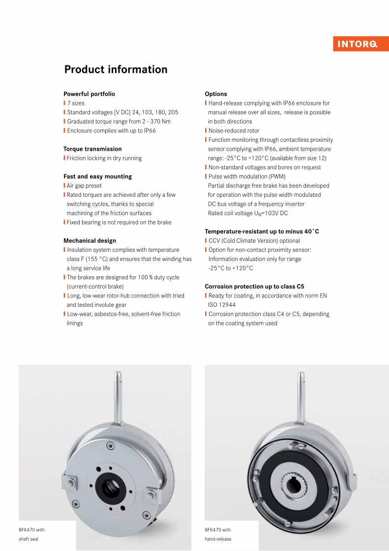
Powerful portfolio❙� 7 sizes❙ Standard voltages [V DC] 24, 103, 180, 205❙ Graduated torque range from 2 - 370 Nm❙ Enclosure complies with up to IP66
Torque transmission❙ Friction locking in dry running
Fast and easy mounting ❙ Air gap preset❙ Rated torques are achieved after only a few switching cycles, thanks to special machining of the friction surfaces ❙ Fixed bearing is not required on the brake
Mechanical design❙ Insulation system complies with temperature class F (155 °C) and ensures that the winding has a long service life❙ The brakes are designed for 100 % duty cycle (current-control brake) ❙ Long, low-wear rotor-hub connection with tried and tested involute gear ❙ Low-wear, asbestos-free, solvent-free friction linings
Options❙ Hand-release complying with IP66 enclosure for manual release over all sizes, release is possible in both directions ❙ Noise-reduced rotor❙ Function monitoring through contactless proximity sensor complying with IP66, ambient temperature range: -25°C to +120°C (available from size 12)❙ Non-standard voltages and bores on request❙ Pulse width modulation (PWM) Partial discharge free brake has been developed for operation with the pulse width modulated DC bus voltage of a frequency inverter Rated coil voltage UN=103V DC
Temperature-resistant up to minus 40˚C ❙ CCV (Cold Climate Version) optional❙ Option for non-contact proximity sensor: Information evaluation only for range -25°C to +120°C
Corrosion protection up to class C5❙ Ready for coating, in accordance with norm EN ISO 12944 ❙ Corrosion protection class C4 or C5, depending on the coating system used
Product information
BFK470 with
hand-release
BFK470 with
shaft seal

6I7 INTORQ I Spring-applied brake BFK470
❙ 1) Predrilled without keyway
❙ 2) Standard keyway in accordance with DIN 6885/1 P9
❙ For high torques and/or reversing mode it is necessary to use a special hub
Size b dJ7 1) dH7 2) d1 d2 d3 d4 d5h7 d6 d7(-0,2/-0,3) d9 d10 d11 d14 d15 d16
H8 d17H8 d18
h8 d19 di da h h1 spec. standard
06 95 10 10/11/12/14/15 3xM4 72 24 H8 48 89 89 89 - 31 8 4xM4 37,7 89 35 89 94 40 60 39 45,2
08 112 10 10/11/12/14/15 /16/17/18/19/20 3xM5 90 32 H8 58 106 106 106 - 42 8 4xM5 49 106 42 106 111 56,1 76,5 43 50
10 137 10 10/11/12/14/15 /16/17/18/19/20 3xM6 112 42 H8 68 130 130 130 - 44 10 4xM5 54 130 44 130 136 66,1 95 51,2 59,35
12 157 14 14/15 /18/20/22/24/25 3xM6 132 52 H7 82 148 148 148 - 52 12 4xM5 64 148 55 148 154 70,1 115 57,2 65,4
14 179 14 20/25/30 3xM8 145 60 H7 100 168 168 168 52 64 12 4xM6 75 168 70 168 175 80 124 67,1 75,3
16 213 15 25/30/35 3xM8 170 68 H7 110 200 200 200 52 74 12 4xM6 85 200 75 200 208 104 149 73,1 85,8
18 243 20 30/35/40/45 6xM8 196 75 H7 125 226 226 226 62 95 14 4xM8 95 226 95 226 235 129 174 83,1 96,4
view W view Xview Wwithout centering
view Xwithout centering
size l l1 l2 l3 l4 l5 min. l6 min. SLN a β1 +3° β2 +3° Y Z
14 30 400 14,3 15,3 12,3 19 20 0,3 +0,10 / -0,10 25° 9° 8° 0,05 0,05
16 30 600 13,2/18,2 ** 14,2 11,2/16,2** 17/22 ** 18 0,3 +0,15 / -0,05 25° 8° 8° 0,08 0,05
18 35 600 19,3 15,3 15,3 23 19 0,4 +0,20 / -0,10 25° 10° 9° 0,1 0,08
** at CCV-execution
size Mk * b d J7 predrilled d H7 standard d1 d2 d3 H7 d4 d5 h7 d6 d7 -0,2/-0,3 d9 d10 d11 d14 d15 d16 H8 d17 H8 d18 h8 d19 di da h h1 h2 h3 h4 h5 h9 h10 h11 h12 h13 min. h13 max. h14 min. h14 max. h15 h16 h17 h18
14 60 Nm 179 14 20/25/30 3xM8 145 60 100 168 168 168 52 64 12 4xM6 75 168 70 168 175 80 124 67,1 75,3 2 6 38,8 185,5 100,5 104,5 0,3 12 10 16 6,5 10 79,4 12 8 4,5
16 80 Nm 213 15 25/30/35 3xM8 170 68 110 200 200 200 52 74 12 4xM6 85 200 75 200 208 104 149 73,1 85,8 2,25 6 42,8 231 118 122 0,3 12 10 16 6,5 10 81,5 12 8 4,5
18 150 Nm 243 20 30/35/40/45 6xM8 196 75 125 226 226 226 62 95 14 4xM8 95 226 95 226 235 129 174 83,1 96,4 2,75 6 47,8 290 135 140 0,3 12 10 16 6,5 10 91,6 16 10 5
* other torques on request / higher torques demanded modified hub design
Ind./ Anz./
ind. quan.
Änder-Nr./
revision no.
Datum/
date
Name/
name
Datum/date Name/name
Bea/drn
Gepr/chkd
Norm/appr
Datei/file
Benennung/name of drawing
Zeichnungsnummer/drawing no.
Ersatz fuer/back-up for
Blatt/sheetCAD
M14.0297.iam
i
Strate
Hanf
10.03.2015
10.03.2015Federkraftbremse
Typ BFK470-14...18
M14.0297-Edrawing with same no. from 18.12.2012
5 - 601385 10.03.2015 STR
5020
1030
40m
m0
Sch
utzv
erm
erk
ISO
160
16 b
each
ten.
Cop
yrig
ht r
eser
ved.
1 2 3 4 5 6 7 8 9 10 11 12
A
B
C
D
E
F
G
H
1 2 3 4 5 6 7 8 9 10 11 12
A
B
C
D
E
F
G
H
W X
d5
SLN
h3 h
d11b
h1
d10 d9
l1
l2
h12
d7 da di
h2
h4
l
β1 β2
h13
l5 l6
h14
brake with flangeat motor end shield(view W)
brake without flangeat motor end shield(view X)
brake withcentering flange
l5
Rz16Rz6,3 in the seal area
c Yh Z Anot convex
c Yh Z Anot convex
R0,4
0,4
0,1
+
15°
2,5 0,2+
view Zbearing shield Z Z
R0,4
h9h5
a
d2
d1
d3 d4
h11
d
d14
d15
h10
d6
h16
l3
h15
c Yh Z Anot convex
proximity switchwith silicone cable
flange back sideshoring completely
d2
M8
jn0,2 B C3x (size 14+16)
B
60/120°
motor end shield(position tolerance ofthe screw holes)
6x (size 18)
Rz10 in the friction areaRz6,3 in the seal area
Rz16Rz6,3 in the seal area
n
A
n
C
d17
d19
d18
h17
n
C
l4
h18
l6
Rz10 in the friction areaRz6,3 in the seal area
c Yh Z Anot convex
d16
h 0,03 A
d16
h 0,03 A
Technical data
BFK470 spring-applied brake Brake with flange
rear side of flange has to be stabilized completely
view W view Xview Wwithout centering
view Xwithout centering
size l l1 l2 l3 l4 l5 min. l6 min. SLN a β1 +3° β2 +3° Y Z
14 30 400 14,3 15,3 12,3 19 20 0,3 +0,10 / -0,10 25° 9° 8° 0,05 0,05
16 30 600 13,2/18,2 ** 14,2 11,2/16,2** 17/22 ** 18 0,3 +0,15 / -0,05 25° 8° 8° 0,08 0,05
18 35 600 19,3 15,3 15,3 23 19 0,4 +0,20 / -0,10 25° 10° 9° 0,1 0,08
** at CCV-execution
size Mk * b d J7 predrilled d H7 standard d1 d2 d3 H7 d4 d5 h7 d6 d7 -0,2/-0,3 d9 d10 d11 d14 d15 d16 H8 d17 H8 d18 h8 d19 di da h h1 h2 h3 h4 h5 h9 h10 h11 h12 h13 min. h13 max. h14 min. h14 max. h15 h16 h17 h18
14 60 Nm 179 14 20/25/30 3xM8 145 60 100 168 168 168 52 64 12 4xM6 75 168 70 168 175 80 124 67,1 75,3 2 6 38,8 185,5 100,5 104,5 0,3 12 10 16 6,5 10 79,4 12 8 4,5
16 80 Nm 213 15 25/30/35 3xM8 170 68 110 200 200 200 52 74 12 4xM6 85 200 75 200 208 104 149 73,1 85,8 2,25 6 42,8 231 118 122 0,3 12 10 16 6,5 10 81,5 12 8 4,5
18 150 Nm 243 20 30/35/40/45 6xM8 196 75 125 226 226 226 62 95 14 4xM8 95 226 95 226 235 129 174 83,1 96,4 2,75 6 47,8 290 135 140 0,3 12 10 16 6,5 10 91,6 16 10 5
* other torques on request / higher torques demanded modified hub design
Ind./ Anz./
ind. quan.
Änder-Nr./
revision no.
Datum/
date
Name/
name
Datum/date Name/name
Bea/drn
Gepr/chkd
Norm/appr
Datei/file
Benennung/name of drawing
Zeichnungsnummer/drawing no.
Ersatz fuer/back-up for
Blatt/sheetCAD
M14.0297.iam
i
Strate
Hanf
10.03.2015
10.03.2015Federkraftbremse
Typ BFK470-14...18
M14.0297-Edrawing with same no. from 18.12.2012
5 - 601385 10.03.2015 STR
5020
1030
40m
m0
Sch
utzv
erm
erk
ISO
160
16 b
each
ten.
Cop
yrig
ht r
eser
ved.
1 2 3 4 5 6 7 8 9 10 11 12
A
B
C
D
E
F
G
H
1 2 3 4 5 6 7 8 9 10 11 12
A
B
C
D
E
F
G
H
W X
d5
SLN
h3 h
d11b
h1
d10 d9
l1
l2
h12
d7 da di
h2
h4
l
β1 β2
h13
l5 l6
h14
brake with flangeat motor end shield(view W)
brake without flangeat motor end shield(view X)
brake withcentering flange
l5
Rz16Rz6,3 in the seal area
c Yh Z Anot convex
c Yh Z Anot convex
R0,4
0,4
0,1
+
15°
2,5 0,2+
view Zbearing shield Z Z
R0,4
h9h5
a
d2
d1
d3 d4
h11
d
d14
d15
h10
d6
h16
l3
h15
c Yh Z Anot convex
proximity switchwith silicone cable
flange back sideshoring completely
d2
M8
jn0,2 B C3x (size 14+16)
B
60/120°
motor end shield(position tolerance ofthe screw holes)
6x (size 18)
Rz10 in the friction areaRz6,3 in the seal area
Rz16Rz6,3 in the seal area
n
A
n
C
d17
d19
d18
h17
n
C
l4
h18
l6
Rz10 in the friction areaRz6,3 in the seal area
c Yh Z Anot convex
d16
h 0,03 A
d16
h 0,03 A
View ZBearing shield
View Wwith centering
Proximity sensorwith silicone cable
Z
Air gap site holeavailable from size 12
Ansicht Wmit Zentrierung
Gr. Mk M * b d J7 vorgebohrt d H7 Standard d1 d2 d3 H7 d4 d5 h7
06 4 Nm 1,5…7 Nm 95 10 10/11/12/14/15 3xM4 72 24 48 8908 3xM5
l1
l5
R0,4
0,4
0,1
+
45°
1,2`0,2
Ansicht ZLagerschild
R0,4
Näherungsschalter mit Silikonkabel
d16
h 0,03 A
aaaa

❙ Measurements in mm
❙ For a key to abbreviations see page 4
Size h2 h3 h4 h5 h9 h10 h11 h12 h13 min. h13 max. h14 min. h14 max. h15 h16 h17 h18 l l1 l2 l3 l4 l5 min l6 min SLN a b1 +3° b 2+3° Y Z
06 1 3,5 20,7 112 54,5 57 0,3 8 6,5 9,5 4,5 6 - 10 4,5 3 18 400 6,8 5,3 5,8 9 7,5 0,2 (+0,08/-0,05) 25° 8,5° 8° 0,03 0,05
08 1 4,5 24,7 119,5 62 64,5 0,3 8 7,5 10,5 4,5 6 - 12 4,5 3 20 400 7,3 7,8 7,8 10 10,5 0,2 (+0,08/-0,05) 25° 8,5° 8° 0,03 0,05
10 2 4,5 26,9 143 77 80 0,3 10 8 12,5 4,5 8 - 12 6,5 4 20 400 10,2 10,7 8,7 13,5 14 0,2 (+0,13/-0,05) 25° 8° 7° 0,03 0,05
12 2 5 30,4 175 90 94 0,3 12 8,5 15 5,0 10 72,0 12 6,5 4 25 400 9,1 9,1 7,6 12,5 12,5 0,3 (+0,08/-0,10) 25° 8,5° 8° 0,05 0,05
14 2 6 38,8 185,5 100,5 104,5 0,3 12 10 16 6,5 10 79,4 12 8 4,5 30 400 14,3 15,3 12,3 19 20 0,3(+0,10/-0,10) 25° 9° 8° 0,05 0,05
16 2.25 6 42,8 231 118 122 0,3 12 10 16 6,5 10 81,5 12 8 4,5 30 600 13,2 14,2 11,2 17 18 0,3(+0,15/-0,05) 25° 8° 8° 0,08 0,05
18 2,75 6 47,8 290 135 140 0,3 12 10 16 6,5 10 91,6 16 10 5 35 600 19,3 15,3 15,3 23 19 0,4(+0,20/-0,10) 25° 10° 9° 0,1 0,08
view W view Xview Wwithout centering
view Xwithout centering
size l l1 l2 l3 l4 l5 min. l6 min. SLN a β1 +3° β2 +3° Y Z
14 30 400 14,3 15,3 12,3 19 20 0,3 +0,10 / -0,10 25° 9° 8° 0,05 0,05
16 30 600 13,2/18,2 ** 14,2 11,2/16,2** 17/22 ** 18 0,3 +0,15 / -0,05 25° 8° 8° 0,08 0,05
18 35 600 19,3 15,3 15,3 23 19 0,4 +0,20 / -0,10 25° 10° 9° 0,1 0,08
** at CCV-execution
size Mk * b d J7 predrilled d H7 standard d1 d2 d3 H7 d4 d5 h7 d6 d7 -0,2/-0,3 d9 d10 d11 d14 d15 d16 H8 d17 H8 d18 h8 d19 di da h h1 h2 h3 h4 h5 h9 h10 h11 h12 h13 min. h13 max. h14 min. h14 max. h15 h16 h17 h18
14 60 Nm 179 14 20/25/30 3xM8 145 60 100 168 168 168 52 64 12 4xM6 75 168 70 168 175 80 124 67,1 75,3 2 6 38,8 185,5 100,5 104,5 0,3 12 10 16 6,5 10 79,4 12 8 4,5
16 80 Nm 213 15 25/30/35 3xM8 170 68 110 200 200 200 52 74 12 4xM6 85 200 75 200 208 104 149 73,1 85,8 2,25 6 42,8 231 118 122 0,3 12 10 16 6,5 10 81,5 12 8 4,5
18 150 Nm 243 20 30/35/40/45 6xM8 196 75 125 226 226 226 62 95 14 4xM8 95 226 95 226 235 129 174 83,1 96,4 2,75 6 47,8 290 135 140 0,3 12 10 16 6,5 10 91,6 16 10 5
* other torques on request / higher torques demanded modified hub design
Ind./ Anz./
ind. quan.
Änder-Nr./
revision no.
Datum/
date
Name/
name
Datum/date Name/name
Bea/drn
Gepr/chkd
Norm/appr
Datei/file
Benennung/name of drawing
Zeichnungsnummer/drawing no.
Ersatz fuer/back-up for
Blatt/sheetCAD
M14.0297.iam
i
Strate
Hanf
10.03.2015
10.03.2015Federkraftbremse
Typ BFK470-14...18
M14.0297-Edrawing with same no. from 18.12.2012
5 - 601385 10.03.2015 STR
5020
1030
40m
m0
Sch
utzv
erm
erk
ISO
160
16 b
each
ten.
Cop
yrig
ht r
eser
ved.
1 2 3 4 5 6 7 8 9 10 11 12
A
B
C
D
E
F
G
H
1 2 3 4 5 6 7 8 9 10 11 12
A
B
C
D
E
F
G
H
W X
d5
SLN
h3 h
d11b
h1
d10 d9
l1
l2
h12
d7 da di
h2
h4
l
β1 β2
h13
l5 l6
h14
brake with flangeat motor end shield(view W)
brake without flangeat motor end shield(view X)
brake withcentering flange
l5
Rz16Rz6,3 in the seal area
c Yh Z Anot convex
c Yh Z Anot convex
R0,4
0,4
0,1
+
15°
2,5 0,2+
view Zbearing shield Z Z
R0,4
h9h5
a
d2
d1
d3 d4h11
d
d14
d15
h10
d6
h16
l3
h15
c Yh Z Anot convex
proximity switchwith silicone cable
flange back sideshoring completely
d2
M8
jn0,2 B C3x (size 14+16)
B
60/120°
motor end shield(position tolerance ofthe screw holes)
6x (size 18)
Rz10 in the friction areaRz6,3 in the seal area
Rz16Rz6,3 in the seal area
n
A
n
C
d17
d19
d18
h17
n
C
l4
h18
l6
Rz10 in the friction areaRz6,3 in the seal area
c Yh Z Anot convex
d16
h 0,03 A
d16
h 0,03 A
view W view Xview Wwithout centering
view Xwithout centering
size l l1 l2 l3 l4 l5 min. l6 min. SLN a β1 +3° β2 +3° Y Z
14 30 400 14,3 15,3 12,3 19 20 0,3 +0,10 / -0,10 25° 9° 8° 0,05 0,05
16 30 600 13,2/18,2 ** 14,2 11,2/16,2** 17/22 ** 18 0,3 +0,15 / -0,05 25° 8° 8° 0,08 0,05
18 35 600 19,3 15,3 15,3 23 19 0,4 +0,20 / -0,10 25° 10° 9° 0,1 0,08
** at CCV-execution
size Mk * b d J7 predrilled d H7 standard d1 d2 d3 H7 d4 d5 h7 d6 d7 -0,2/-0,3 d9 d10 d11 d14 d15 d16 H8 d17 H8 d18 h8 d19 di da h h1 h2 h3 h4 h5 h9 h10 h11 h12 h13 min. h13 max. h14 min. h14 max. h15 h16 h17 h18
14 60 Nm 179 14 20/25/30 3xM8 145 60 100 168 168 168 52 64 12 4xM6 75 168 70 168 175 80 124 67,1 75,3 2 6 38,8 185,5 100,5 104,5 0,3 12 10 16 6,5 10 79,4 12 8 4,5
16 80 Nm 213 15 25/30/35 3xM8 170 68 110 200 200 200 52 74 12 4xM6 85 200 75 200 208 104 149 73,1 85,8 2,25 6 42,8 231 118 122 0,3 12 10 16 6,5 10 81,5 12 8 4,5
18 150 Nm 243 20 30/35/40/45 6xM8 196 75 125 226 226 226 62 95 14 4xM8 95 226 95 226 235 129 174 83,1 96,4 2,75 6 47,8 290 135 140 0,3 12 10 16 6,5 10 91,6 16 10 5
* other torques on request / higher torques demanded modified hub design
Ind./ Anz./
ind. quan.
Änder-Nr./
revision no.
Datum/
date
Name/
name
Datum/date Name/name
Bea/drn
Gepr/chkd
Norm/appr
Datei/file
Benennung/name of drawing
Zeichnungsnummer/drawing no.
Ersatz fuer/back-up for
Blatt/sheetCAD
M14.0297.iam
i
Strate
Hanf
10.03.2015
10.03.2015Federkraftbremse
Typ BFK470-14...18
M14.0297-Edrawing with same no. from 18.12.2012
5 - 601385 10.03.2015 STR
5020
1030
40m
m0
Sch
utzv
erm
erk
ISO
160
16 b
each
ten.
Cop
yrig
ht r
eser
ved.
1 2 3 4 5 6 7 8 9 10 11 12
A
B
C
D
E
F
G
H
1 2 3 4 5 6 7 8 9 10 11 12
A
B
C
D
E
F
G
H
W X
d5
SLN
h3 h
d11b
h1
d10 d9
l1
l2
h12
d7 da di
h2
h4
l
β1 β2
h13
l5 l6
h14
brake with flangeat motor end shield(view W)
brake without flangeat motor end shield(view X)
brake withcentering flange
l5
Rz16Rz6,3 in the seal area
c Yh Z Anot convex
c Yh Z Anot convex
R0,4
0,4
0,1
+
15°
2,5 0,2+
view Zbearing shield Z Z
R0,4
h9h5
a
d2
d1
d3 d4
h11
d
d14
d15
h10
d6
h16
l3
h15
c Yh Z Anot convex
proximity switchwith silicone cable
flange back sideshoring completely
d2
M8
jn0,2 B C3x (size 14+16)
B
60/120°
motor end shield(position tolerance ofthe screw holes)
6x (size 18)
Rz10 in the friction areaRz6,3 in the seal area
Rz16Rz6,3 in the seal area
n
A
n
Cd1
7
d19
d18
h17n
C
l4
h18
l6
Rz10 in the friction areaRz6,3 in the seal area
c Yh Z Anot convex
d16
h 0,03 A
d16
h 0,03 A
Brake without flange Brake with centering flange
Motor mounting plate(position tolerance ofthe screw holes)
view W view Xview Wwithout centering
view Xwithout centering
size l l1 l2 l3 l4 l5 min. l6 min. SLN a β1 +3° β2 +3° Y Z
14 30 400 14,3 15,3 12,3 19 20 0,3 +0,10 / -0,10 25° 9° 8° 0,05 0,05
16 30 600 13,2/18,2 ** 14,2 11,2/16,2** 17/22 ** 18 0,3 +0,15 / -0,05 25° 8° 8° 0,08 0,05
18 35 600 19,3 15,3 15,3 23 19 0,4 +0,20 / -0,10 25° 10° 9° 0,1 0,08
** at CCV-execution
size Mk * b d J7 predrilled d H7 standard d1 d2 d3 H7 d4 d5 h7 d6 d7 -0,2/-0,3 d9 d10 d11 d14 d15 d16 H8 d17 H8 d18 h8 d19 di da h h1 h2 h3 h4 h5 h9 h10 h11 h12 h13 min. h13 max. h14 min. h14 max. h15 h16 h17 h18
14 60 Nm 179 14 20/25/30 3xM8 145 60 100 168 168 168 52 64 12 4xM6 75 168 70 168 175 80 124 67,1 75,3 2 6 38,8 185,5 100,5 104,5 0,3 12 10 16 6,5 10 79,4 12 8 4,5
16 80 Nm 213 15 25/30/35 3xM8 170 68 110 200 200 200 52 74 12 4xM6 85 200 75 200 208 104 149 73,1 85,8 2,25 6 42,8 231 118 122 0,3 12 10 16 6,5 10 81,5 12 8 4,5
18 150 Nm 243 20 30/35/40/45 6xM8 196 75 125 226 226 226 62 95 14 4xM8 95 226 95 226 235 129 174 83,1 96,4 2,75 6 47,8 290 135 140 0,3 12 10 16 6,5 10 91,6 16 10 5
* other torques on request / higher torques demanded modified hub design
Ind./ Anz./
ind. quan.
Änder-Nr./
revision no.
Datum/
date
Name/
name
Datum/date Name/name
Bea/drn
Gepr/chkd
Norm/appr
Datei/file
Benennung/name of drawing
Zeichnungsnummer/drawing no.
Ersatz fuer/back-up for
Blatt/sheetCAD
M14.0297.iam
i
Strate
Hanf
10.03.2015
10.03.2015Federkraftbremse
Typ BFK470-14...18
M14.0297-Edrawing with same no. from 18.12.2012
5 - 601385 10.03.2015 STR
5020
1030
40m
m0
Sch
utzv
erm
erk
ISO
160
16 b
each
ten.
Cop
yrig
ht r
eser
ved.
1 2 3 4 5 6 7 8 9 10 11 12
A
B
C
D
E
F
G
H
1 2 3 4 5 6 7 8 9 10 11 12
A
B
C
D
E
F
G
H
W X
d5
SLN
h3 h
d11b
h1
d10 d9
l1
l2
h12
d7 da di
h2
h4
l
β1 β2
h13
l5 l6
h14
brake with flangeat motor end shield(view W)
brake without flangeat motor end shield(view X)
brake withcentering flange
l5
Rz16Rz6,3 in the seal area
c Yh Z Anot convex
c Yh Z Anot convex
R0,4
0,4
0,1
+
15°
2,5 0,2+
view Zbearing shield Z Z
R0,4
h9h5
a
d2
d1
d3 d4
h11
d
d14
d15
h10
d6
h16
l3
h15
c Yh Z Anot convex
proximity switchwith silicone cable
flange back sideshoring completely
d2
M8
jn0,2 B C3x (size 14+16)
B
60/120°
motor end shield(position tolerance ofthe screw holes)
6x (size 18)
Rz10 in the friction areaRz6,3 in the seal area
Rz16Rz6,3 in the seal area
n
A
n
C
d17
d19
d18
h17n
C
l4
h18
l6
Rz10 in the friction areaRz6,3 in the seal area
c Yh Z Anot convex
d16
h 0,03 A
d16
h 0,03 A
view W view Xview Wwithout centering
view Xwithout centering
size l l1 l2 l3 l4 l5 min. l6 min. SLN a β1 +3° β2 +3° Y Z
14 30 400 14,3 15,3 12,3 19 20 0,3 +0,10 / -0,10 25° 9° 8° 0,05 0,05
16 30 600 13,2/18,2 ** 14,2 11,2/16,2** 17/22 ** 18 0,3 +0,15 / -0,05 25° 8° 8° 0,08 0,05
18 35 600 19,3 15,3 15,3 23 19 0,4 +0,20 / -0,10 25° 10° 9° 0,1 0,08
** at CCV-execution
size Mk * b d J7 predrilled d H7 standard d1 d2 d3 H7 d4 d5 h7 d6 d7 -0,2/-0,3 d9 d10 d11 d14 d15 d16 H8 d17 H8 d18 h8 d19 di da h h1 h2 h3 h4 h5 h9 h10 h11 h12 h13 min. h13 max. h14 min. h14 max. h15 h16 h17 h18
14 60 Nm 179 14 20/25/30 3xM8 145 60 100 168 168 168 52 64 12 4xM6 75 168 70 168 175 80 124 67,1 75,3 2 6 38,8 185,5 100,5 104,5 0,3 12 10 16 6,5 10 79,4 12 8 4,5
16 80 Nm 213 15 25/30/35 3xM8 170 68 110 200 200 200 52 74 12 4xM6 85 200 75 200 208 104 149 73,1 85,8 2,25 6 42,8 231 118 122 0,3 12 10 16 6,5 10 81,5 12 8 4,5
18 150 Nm 243 20 30/35/40/45 6xM8 196 75 125 226 226 226 62 95 14 4xM8 95 226 95 226 235 129 174 83,1 96,4 2,75 6 47,8 290 135 140 0,3 12 10 16 6,5 10 91,6 16 10 5
* other torques on request / higher torques demanded modified hub design
Ind./ Anz./
ind. quan.
Änder-Nr./
revision no.
Datum/
date
Name/
name
Datum/date Name/name
Bea/drn
Gepr/chkd
Norm/appr
Datei/file
Benennung/name of drawing
Zeichnungsnummer/drawing no.
Ersatz fuer/back-up for
Blatt/sheetCAD
M14.0297.iam
i
Strate
Hanf
10.03.2015
10.03.2015Federkraftbremse
Typ BFK470-14...18
M14.0297-Edrawing with same no. from 18.12.2012
5 - 601385 10.03.2015 STR
5020
1030
40m
m0
Sch
utzv
erm
erk
ISO
160
16 b
each
ten.
Cop
yrig
ht r
eser
ved.
1 2 3 4 5 6 7 8 9 10 11 12
A
B
C
D
E
F
G
H
1 2 3 4 5 6 7 8 9 10 11 12
A
B
C
D
E
F
G
H
W X
d5
SLN
h3 h
d11b
h1
d10 d9
l1
l2
h12
d7 da di
h2
h4
l
β1 β2
h13
l5 l6
h14
brake with flangeat motor end shield(view W)
brake without flangeat motor end shield(view X)
brake withcentering flange
l5
Rz16Rz6,3 in the seal area
c Yh Z Anot convex
c Yh Z Anot convex
R0,4
0,4
0,1
+
15°
2,5 0,2+
view Zbearing shield Z Z
R0,4
h9h5
a
d2
d1
d3 d4
h11
d
d14
d15
h10
d6
h16
l3
h15
c Yh Z Anot convex
proximity switchwith silicone cable
flange back sideshoring completely
d2
M8
jn0,2 B C3x (size 14+16)
B
60/120°
motor end shield(position tolerance ofthe screw holes)
6x (size 18)
Rz10 in the friction areaRz6,3 in the seal area
Rz16Rz6,3 in the seal area
n
A
n
C
d17
d19
d18
h17
n
C
l4
h18
l6
Rz10 in the friction areaRz6,3 in the seal area
c Yh Z Anot convex
d16
h 0,03 A
d16
h 0,03 A
view W view Xview Wwithout centering
view Xwithout centering
size l l1 l2 l3 l4 l5 min. l6 min. SLN a β1 +3° β2 +3° Y Z
14 30 400 14,3 15,3 12,3 19 20 0,3 +0,10 / -0,10 25° 9° 8° 0,05 0,05
16 30 600 13,2/18,2 ** 14,2 11,2/16,2** 17/22 ** 18 0,3 +0,15 / -0,05 25° 8° 8° 0,08 0,05
18 35 600 19,3 15,3 15,3 23 19 0,4 +0,20 / -0,10 25° 10° 9° 0,1 0,08
** at CCV-execution
size Mk * b d J7 predrilled d H7 standard d1 d2 d3 H7 d4 d5 h7 d6 d7 -0,2/-0,3 d9 d10 d11 d14 d15 d16 H8 d17 H8 d18 h8 d19 di da h h1 h2 h3 h4 h5 h9 h10 h11 h12 h13 min. h13 max. h14 min. h14 max. h15 h16 h17 h18
14 60 Nm 179 14 20/25/30 3xM8 145 60 100 168 168 168 52 64 12 4xM6 75 168 70 168 175 80 124 67,1 75,3 2 6 38,8 185,5 100,5 104,5 0,3 12 10 16 6,5 10 79,4 12 8 4,5
16 80 Nm 213 15 25/30/35 3xM8 170 68 110 200 200 200 52 74 12 4xM6 85 200 75 200 208 104 149 73,1 85,8 2,25 6 42,8 231 118 122 0,3 12 10 16 6,5 10 81,5 12 8 4,5
18 150 Nm 243 20 30/35/40/45 6xM8 196 75 125 226 226 226 62 95 14 4xM8 95 226 95 226 235 129 174 83,1 96,4 2,75 6 47,8 290 135 140 0,3 12 10 16 6,5 10 91,6 16 10 5
* other torques on request / higher torques demanded modified hub design
Ind./ Anz./
ind. quan.
Änder-Nr./
revision no.
Datum/
date
Name/
name
Datum/date Name/name
Bea/drn
Gepr/chkd
Norm/appr
Datei/file
Benennung/name of drawing
Zeichnungsnummer/drawing no.
Ersatz fuer/back-up for
Blatt/sheetCAD
M14.0297.iam
i
Strate
Hanf
10.03.2015
10.03.2015Federkraftbremse
Typ BFK470-14...18
M14.0297-Edrawing with same no. from 18.12.2012
5 - 601385 10.03.2015 STR
5020
1030
40m
m0
Sch
utzv
erm
erk
ISO
160
16 b
each
ten.
Cop
yrig
ht r
eser
ved.
1 2 3 4 5 6 7 8 9 10 11 12
A
B
C
D
E
F
G
H
1 2 3 4 5 6 7 8 9 10 11 12
A
B
C
D
E
F
G
H
W X
d5
SLN
h3 h
d11b
h1
d10 d9
l1
l2
h12
d7 da di
h2
h4
l
β1 β2
h13
l5 l6
h14
brake with flangeat motor end shield(view W)
brake without flangeat motor end shield(view X)
brake withcentering flange
l5
Rz16Rz6,3 in the seal area
c Yh Z Anot convex
c Yh Z Anot convex
R0,4
0,4
0,1
+
15°
2,5 0,2+
view Zbearing shield Z Z
R0,4
h9h5
a
d2
d1
d3 d4
h11
d
d14
d15
h10
d6
h16
l3
h15
c Yh Z Anot convex
proximity switchwith silicone cable
flange back sideshoring completely
d2
M8
jn0,2 B C3x (size 14+16)
B
60/120°
motor end shield(position tolerance ofthe screw holes)
6x (size 18)
Rz10 in the friction areaRz6,3 in the seal area
Rz16Rz6,3 in the seal area
n
A
n
C
d17
d19
d18
h17n
C
l4
h18
l6
Rz10 in the friction areaRz6,3 in the seal area
c Yh Z Anot convex
d16
h 0,03 A
d16
h 0,03 A
View Wwithout centering
View Xwith centering
View Xwithout centering
Z
INTORQ I Spring-applied brake BFK4708I9
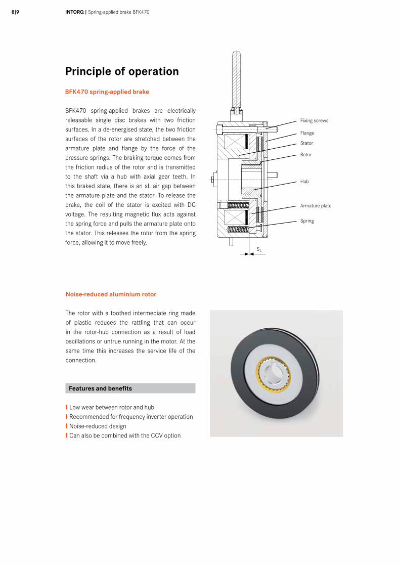
Principle of operation
BFK470 spring-applied brake
BFK470 spring-applied brakes are electrically releasable single disc brakes with two friction surfaces. In a de-energised state, the two friction surfaces of the rotor are stretched between the armature plate and flange by the force of the pressure springs. The braking torque comes from the friction radius of the rotor and is transmitted to the shaft via a hub with axial gear teeth. In this braked state, there is an sL air gap between the armature plate and the stator. To release the brake, the coil of the stator is excited with DC voltage. The resulting magnetic flux acts against the spring force and pulls the armature plate onto the stator. This releases the rotor from the spring force, allowing it to move freely.
050
mm
3040
1020
1 2 3 4 5 6 7 8 9 10
A
B
C
D
E
F
G
H
Fixing screws
Flange
Stator
Rotor
Hub
Armature plate
Spring
Noise-reduced aluminium rotor
The rotor with a toothed intermediate ring made of plastic reduces the rattling that can occur in the rotor-hub connection as a result of load oscillations or untrue running in the motor. At the same time this increases the service life of the connection.
Features and benefits
❙ Low wear between rotor and hub ❙ Recommended for frequency inverter operation❙ Noise-reduced design❙ Can also be combined with the CCV option
SL

INTORQ brakes are designed so that the rated torques specified for 100r/min can be achieved after a short run-in period. This is ensured by using tightly toleranced components and a controlled assembly process.
Deviations from the specified braking torques are possible as a result of varying environmental conditions and fluctuations in the properties of the organic friction linings being used. These possible deviations should be allowed for by taking the appropriate precautions in the dimensioning process.
Increased breakaway can occur especially after long downtimes where there are damp conditions and varying temperatures. The rated torque must be checked if the brake is being used on the customer’s own friction surfaces. If the brake is to be used purely as a holding brake with no dynamic load, the friction lining must be reactivated at regular intervals.
Rated torques
General information Tolerances in the braking torque
As a result of the tolerances of springs and friction linings, the tolerance range for the braking torque in the BFK470 is❙ -15%/+25% for brakes with adjustable spring force (sizes 12 … 18) and❙ -25%/+35% for brakes without adjustable spring force (sizes 06 … 10).
Speed, temperature and dampness are factors that influence the braking torque. The ideal run-in process requires 10 full cycles of the brake from a speed of 1500r/min with friction work of 50% QE each time. If an adequate run-in process is not possible during commissioning, especially with holding brakes, the braking torque must be increased accordingly in the dimensioning process. INTORQ offers special friction linings for increased torques, quick running-in periods or high braking energies. We welcome the opportunity to review your application and show you how INTORQ can add value to your system and meet any special demands you may have.
❙ For a key to abbreviations see page 4
Rated torques
Operating brake (sLmax ca. 2.5 x sLN)
Standard braking torque Holding brake with emergency stop (sLmax ca. 1.5 x sLN)
Size 06 08 10 12 14 16 18
12
2 3,5 15
2,5 5 9 18
3 6 11 23 40 55 100
3,5 7 14 27 50 70 125
4 8 16 32 60 80 150
4,5 10 18 36 65 90 165
5,5 11 21 40 70 100 185
6 12 23 45 75 105 200
6,5 14 25 48 80 125 235
7 15 30 50 100 150 250
7,5 33 55 110
36
up to 10 up to 17 up to 46 up to 68 up to 150 up to 200 up to 370
Operating brake
Holding brake withemergency stops
On request for project solutions
Rated torque MK [Nm] of the brake, rated value at a relative speed of 100 r/min

INTORQ I Spring-applied brake BFK47010 I11
Friction lining variants
Standard and wear-resistant linings
The listed torque ratings and permissible friction work can be combined with any of the brake design options. The catalogue variants are available from a quantity of 1 up to series production levels.
ST (Standard)❙ For universal use❙ Large speed range❙ Short run-in process required❙ Can be used as holding brakes or operating brakes
WR (wear-resistant)❙ Long service life❙ Can be used in standard applications ❙ Restricted maximum speed ❙ Short run-in process required❙ Best for use as a an operating brake
Project solutions
For project solutions INTORQ develops customised series production products on the basis of the customer’s technical specifications. The following friction lining qualities are available for project solutions in addition to the catalogue variants:
HFC (high friction coefficient)❙ For higher braking torques ❙ For use as a holding brake ❙ Short run-in process required
RIF (run in free)❙ Stable static torque ❙ For use as a holding brake ❙ No run-in needed ❙ Developed for high demands ❙ Restricted maximum speed
HT (high temperature)❙ Friction lining resistant to high temperatures to allow friction work up to a factor of 5 (compared with the standard aluminium rotor)❙ Stable static torque❙ Resistant to the effects of dampness and humidity
Characteristic torques
Rated torques characteristics
❙Speed reduction applies to Standard and WR. For WR linings, see the
permissible switching energies listed on page 12.
❙The permissible maximum speed relates to the standard friction lining
❙ For a key to abbreviations, see page 4
Size Rated torque MK [Nm] Reduction of rated torque at specified speed to x% Maximum speed nmax [r/min] 1500 r/min 3000 r/min max.
06 4 87% 80% 74% 6,000
08 8 85% 78% 73% 5,000
10 16 83% 76% 73% 4,000
12 32 81% 74% 73% 3,600
14 60 80% 73% 72% 3,600
16 80 79% 72% 70% 3,600
18 150 77% 70% 68% 3,600
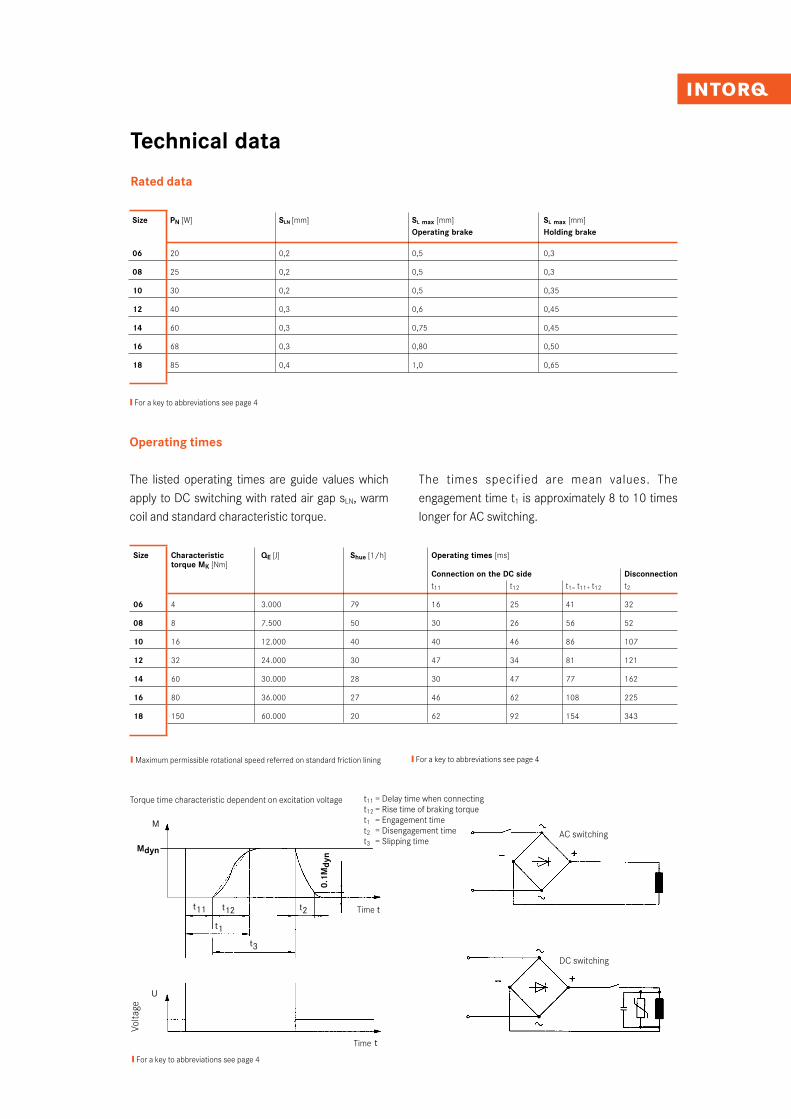
Technical data
Rated data
Size PN [W] SLN [mm] SL max [mm] SL max [mm] Operating brake Holding brake
06 20 0,2 0,5 0,3
08 25 0,2 0,5 0,3
10 30 0,2 0,5 0,35
12 40 0,3 0,6 0,45
14 60 0,3 0,75 0,45
16 68 0,3 0,80 0,50
18 85 0,4 1,0 0,65
Size Characteristic QE [J] Shue [1/h] Operating times [ms] torque MK [Nm] Connection on the DC side Disconnection t11 t12 t1= t11+ t12 t2
06 4 3.000 79 16 25 41 32
08 8 7.500 50 30 26 56 52
10 16 12.000 40 40 46 86 107
12 32 24.000 30 47 34 81 121
14 60 30.000 28 30 47 77 162
16 80 36.000 27 46 62 108 225
18 150 60.000 20 62 92 154 343
❙�Maximum permissible rotational speed referred on standard friction lining ❙ For a key to abbreviations see page 4
❙ For a key to abbreviations see page 4
❙ For a key to abbreviations see page 4
Operating times
The listed operating times are guide values which apply to DC switching with rated air gap sLN, warm coil and standard characteristic torque.
The times specified are mean values. The engagement time t1 is approximately 8 to 10 times longer for AC switching.
AC switching
DC switching
Torque time characteristic dependent on excitation voltage
Volta
ge
Time
Time
M
Mdyn
U
t3
t2t11 t12
t1
t
t
0.1M
dyn
t11 = Delay time when connectingt12 = Rise time of braking torquet1 = Engagement timet2 = Disengagement timet3 = Slipping time
INTORQ I Spring-applied brake BFK47012I13
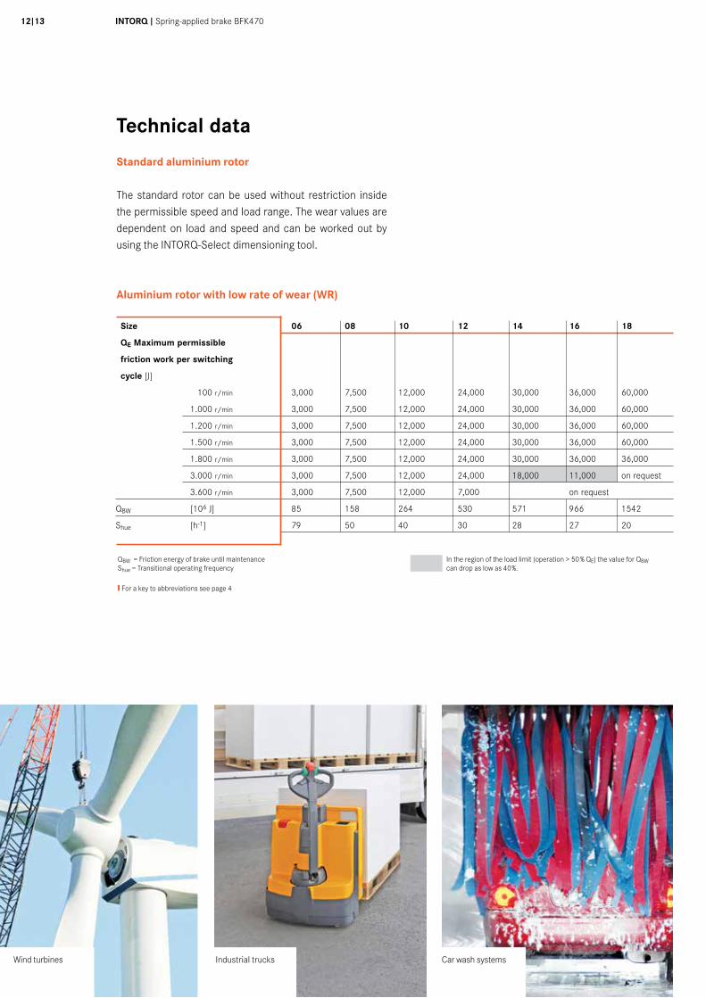
Technical data
Standard aluminium rotor
The standard rotor can be used without restriction inside the permissible speed and load range. The wear values are dependent on load and speed and can be worked out by using the INTORQ-Select dimensioning tool.
Aluminium rotor with low rate of wear (WR)
Car wash systemsIndustrial trucksWind turbines
❙ For a key to abbreviations see page 4
QBW = Friction energy of brake until maintenanceShue = Transitional operating frequency
In the region of the load limit (operation > 50 % QE) the value for QBW can drop as low as 40%.
Size 06 08 10 12 14 16 18
QE Maximum permissible
friction work per switching
cycle [J]
3,000 7,500 12,000 24,000 30,000 36,000 60,000
3,000 7,500 12,000 24,000 30,000 36,000 60,000
3,000 7,500 12,000 24,000 30,000 36,000 60,000
3,000 7,500 12,000 24,000 30,000 36,000 60,000
3,000 7,500 12,000 24,000 30,000 36,000 36,000
3,000 7,500 12,000 24,000 18,000 11,000 on request
3,000 7,500 12,000 7,000 on request
QBW [106 J] 85 158 264 530 571 966 1542
Shue [h-1] 79 50 40 30 28 27 20
100 r/min
1.000 r/min
1.200 r/min
1.500 r/min
1.800 r/min
3.000 r/min
3.600 r/min
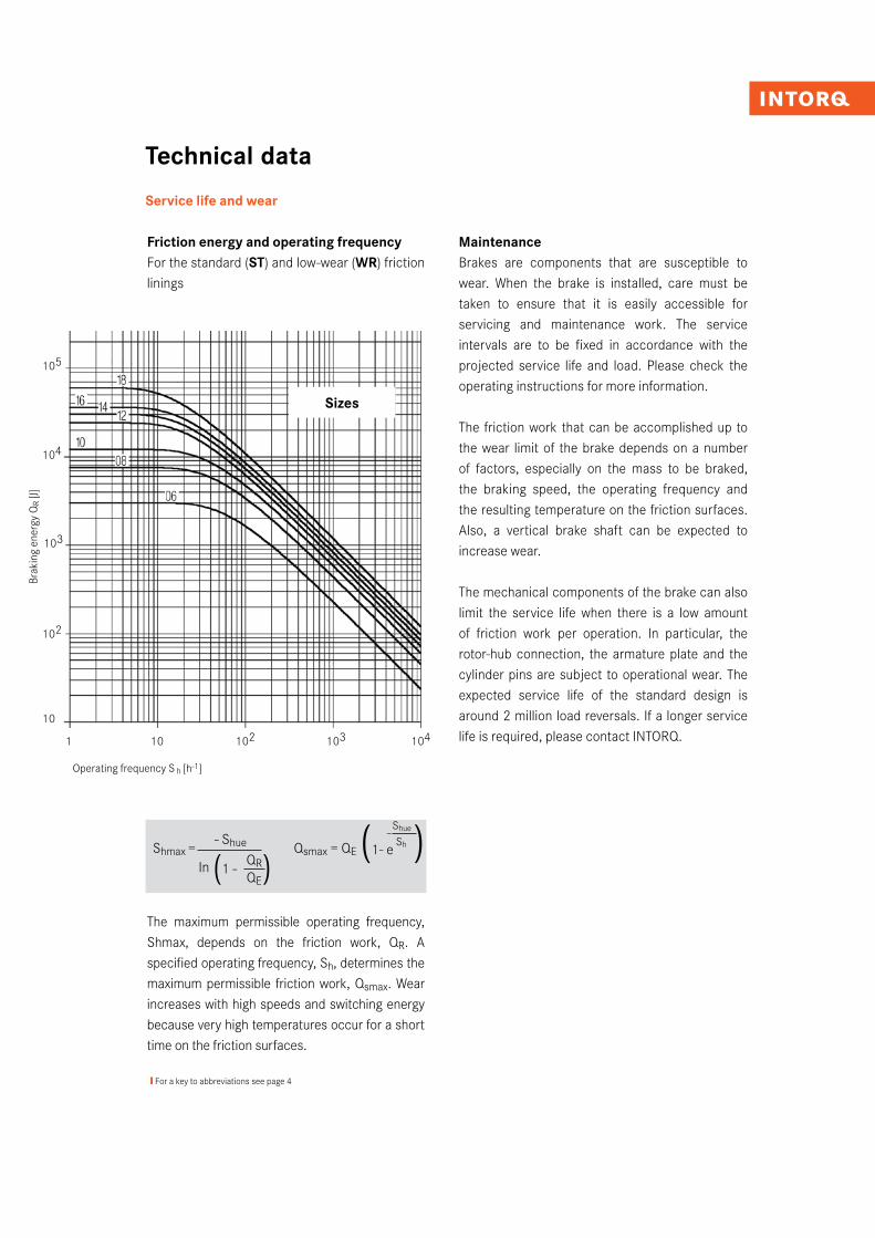
Technical data
Service life and wear
Friction energy and operating frequencyFor the standard (ST) and low-wear (WR) friction linings
The maximum permissible operating frequency, Shmax, depends on the friction work, QR. A specified operating frequency, Sh, determines the maximum permissible friction work, Qsmax. Wear increases with high speeds and switching energy because very high temperatures occur for a short time on the friction surfaces.
MaintenanceBrakes are components that are susceptible to wear. When the brake is installed, care must be taken to ensure that it is easily accessible for servicing and maintenance work. The service intervals are to be fixed in accordance with the projected service life and load. Please check the operating instructions for more information.
The friction work that can be accomplished up to the wear limit of the brake depends on a number of factors, especially on the mass to be braked, the braking speed, the operating frequency and the resulting temperature on the friction surfaces. Also, a vertical brake shaft can be expected to increase wear.
The mechanical components of the brake can also limit the service life when there is a low amount of friction work per operation. In particular, the rotor-hub connection, the armature plate and the cylinder pins are subject to operational wear. The expected service life of the standard design is around 2 million load reversals. If a longer service life is required, please contact INTORQ.
Shmax = - Shue Qsmax = QE
(1- e-Shue )
In (1 - QR)
Sh
QE
❙ For a key to abbreviations see page 4
105
104
103
102
Brak
ing
ener
gy Q
R [J]
10
Operating frequency S h [h-1]
Sizes
1 10 102 103 104

INTORQ I Spring-applied brake BFK47014I15
Product overview
BFK470 spring-applied brake
Size ò 06 ò 08 ò 10 ò 12 ò 14 ò 16 ò 18
Design ò without flange ò standard flange ò centering flange
Voltage Size 6 – 12
ò 24 V ò 96 V ò 103 V ò 170 V ò 180 V ò 190 V ò 205 V
Size 14 – 18
ò 24 V ò 103 V ò 180 V ò 205 V
additional voltages available per request
Characteristic torque ò 2 - 370 Nm (see torque ratings on page 9) Nm
Cable length ò Size 6 – 14: 400 mm ò Size 16 – 18: 600 mm
ò Special lengths: from 100 – 1000 mm in 100 mm graduations
from 1000 – 2500 mm in 250 mm graduations
Temperature range ò Standard -20 to +50˚C
ò CCV, Cold Climate Version -40 to +50˚C
Hand release ò Standard mounting
mounted
Tacho mounting ò Bores on rear side
Contactless ò Switching function monitoring only available as holding brake
proximity sensor (wear monitoring not possible)
(available from size 12) Information evaluation only for range -25°C to +120°C
Cap ò Basic version ò Metal version type
Shaft sealing ring ò On request mm
Rotor ò Aluminium
ò Aluminium, noise reduced (with toothed intermediate ring)
Hub ò Bore diameter (see measurements dH7 on page 6) mm
Fixing ò For mounting with flange ò For mounting without flange
srew set

We are available to our customers at all times and in all locations. Major customers and projects are supported directly by our Key Account Sales Team at our HQ in Aerzen (Germany) or by our locations in Shanghai (China), Atlanta (USA) and Pune (India).
In addition to this, we work with a global network of local trading partners and cooperate with Lenze's global sales organisation.
Please send service requests directly to your local sales partner or to our HQ in Aerzen, Germany:E-mail [email protected]: +49 5154 70534-444Fax: +49 5154 70534-200
You can find more information on our products, as well as catalogues and operating instructions available for download, on our website at www.intorq.de
Setting standards in the market, worldwide
INTORQ GmbH & Co. KG
Postfach 1103D-31849 Aerzen, Germany
Wülmser Weg 5D-31855 Aerzen, Germany
Tel: +49 5154 70534-0Fax: +49 5154 70534-200E-mail [email protected]
INTORQ (Shanghai) CO., LTDChina
No. 600, Xin Yuan Nan Road,Building No. 6 / Zone BNicheng town, PudongShanghai, China 201306
Tel: +86 21 20363-810Fax: +86 21 20363-805E-mail [email protected]
INTORQ US INC.USA
300 Lake Ridge Drive SESmyrna, GA 30082, USA
Tel: +1 678 236-0555Fax: +1 678 309-1157E-mail [email protected]
INTORQ India Pvt. Ltd.India
Plot No. E-7/3, Chakan Industrial Area, Phase 3, Nighoje, Taluka-Khed, Pune, 410501 Maharashtra
Tel: +91 21 3562-5500E-mail [email protected]
www.intorq.com3300
2343
Su
bjec
t to
tech
nica
l alte
ratio
ns ❚
Prin
ted
in G
erm
any
10.2
016
en ❚
5.1