bfs 935 bfs 1345 - wacker neusonproducts.wackerneuson.com/manuals/operators/0203600en_010.pdf ·...
TRANSCRIPT

Operator's manual
Floor saw
BFS 935BFS 1345
0203600en 01008.2011

ManufacturerWacker Neuson Produktion GmbH & Co. KGPreußenstraße 4180809 Münchenwww.wackerneuson.com Tel.: +49-(0)89-354 02-0Fax: +49-(0)89-354 02-390
Translation of the original operator's manual in German
1
1 Foreword .................................................................................................................... 2
2 Introduction ............................................................................................................... 32.1 Means of representation for this operator's manual ........................................... 32.2 Wacker Neuson representative .......................................................................... 42.3 Described machine types ................................................................................... 42.4 Identification of the machine............................................................................... 5
3 Safety ......................................................................................................................... 63.1 Principle.............................................................................................................. 63.2 Qualification of the operating personnel ............................................................. 93.3 Protective gear ................................................................................................. 103.4 Transport .......................................................................................................... 113.5 Operating safety ............................................................................................... 123.6 Safety during the operation of combustion engines ......................................... 153.7 Safety during floor saw operation..................................................................... 173.8 Maintenance..................................................................................................... 193.9 Safety devices .................................................................................................. 21
4 Safety and information labels ................................................................................ 22
5 Technical data ......................................................................................................... 24
6 Accessories ............................................................................................................. 476.1 Parking brake (not for BFS...Z)......................................................................... 476.2 Parking brake (for BFS...Z only) ....................................................................... 49
7 Troubleshooting ...................................................................................................... 52
Contents
1 Foreword
2
1 Foreword
This operator's manual contains information and procedures for the safe opera-tion and maintenance of your Wacker Neuson machine. In the interest of your own safety and to prevent accidents, you should carefully read through the safety information, familiarize yourself with it and observe it at all times.This operator's manual is not a manual for extensive maintenance and repair work. Such work should be carried out by Wacker Neuson service or authorized specialists.
The safety of the operator was one of the most important aspects taken into con-sideration when this machine was designed. Nevertheless, improper use or in-correct maintenance can pose a risk. Please operate and maintain your Wacker Neuson machine in accordance with the instructions in this operator's manual. Your reward will be troublefree operation and a high degree of availability.
Defective machine parts must be replaced immediately!Please contact your Wacker Neuson representative if you have any questions concerning operation or maintenance.
All rights reserved, especially reproduction and distribution rights.Copyright 2011 Wacker Neuson Produktion GmbH & Co. KG
No part of this publication may be reproduced in any form or by any means, elec-tronic or mechanical, including photocopying, without the expressed written per-mission of Wacker Neuson.Any type of reproduction, distribution or storage on data media of any type and form not authorized by Wacker Neuson represents an infringement of copyright and will be prosecuted. We expressly reserve the right to make technical modifications – even without special notice – which aim at further improving our machines or their safety stan-dards.
2 Introduction
3
2 Introduction
2.1 Means of representation for this operator's manual
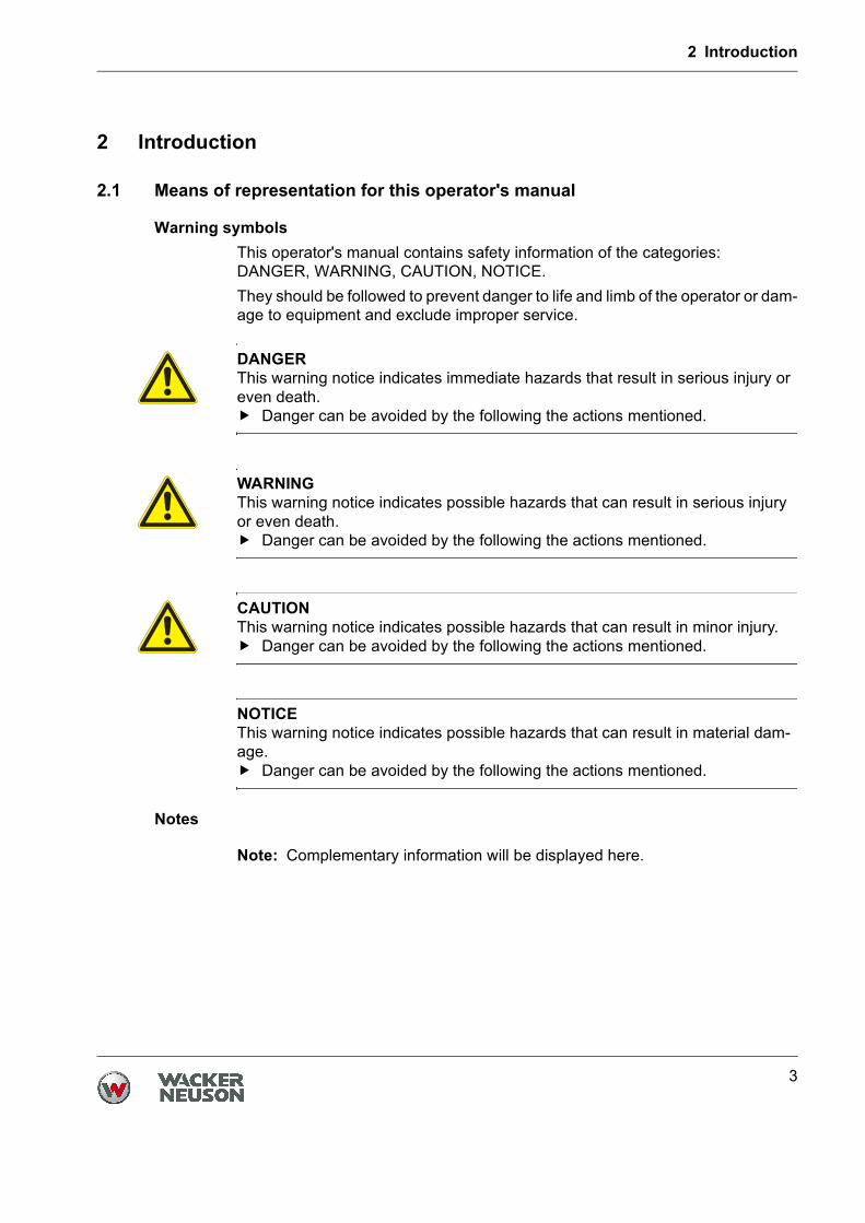
Warning symbolsThis operator's manual contains safety information of the categories: DANGER, WARNING, CAUTION, NOTICE.They should be followed to prevent danger to life and limb of the operator or dam-age to equipment and exclude improper service.
Notes
Note: Complementary information will be displayed here.
DANGERThis warning notice indicates immediate hazards that result in serious injury or even death.
Danger can be avoided by the following the actions mentioned.
WARNINGThis warning notice indicates possible hazards that can result in serious injury or even death.
Danger can be avoided by the following the actions mentioned.
CAUTIONThis warning notice indicates possible hazards that can result in minor injury.
Danger can be avoided by the following the actions mentioned.
NOTICEThis warning notice indicates possible hazards that can result in material dam-age.
Danger can be avoided by the following the actions mentioned.
2 Introduction
4
Instructions This symbol indicates there is something for you to do.
1. Numbered instructions indicate that you have to carry out something in a defined sequence.
This symbol is used for lists.
2.2 Wacker Neuson representative
Depending on your country, your Wacker Neuson representative is your Wacker Neuson service, your Wacker Neuson affiliate or your Wacker Neuson dealer.You can find the addresses in the Internet at www.wackerneuson.com.The address of the manufacturer is located at the beginning of this operator's manual.
2.3 Described machine types
This operator's manual is valid for different machine types from a product range. Therefore some figures can differ from the actual appearance of your machine. It is also possible that the descriptions include components which are not a part of your machine. Details for the described machine types can be found in the chapter Technical data.
2 Introduction
5
2.4 Identification of the machine
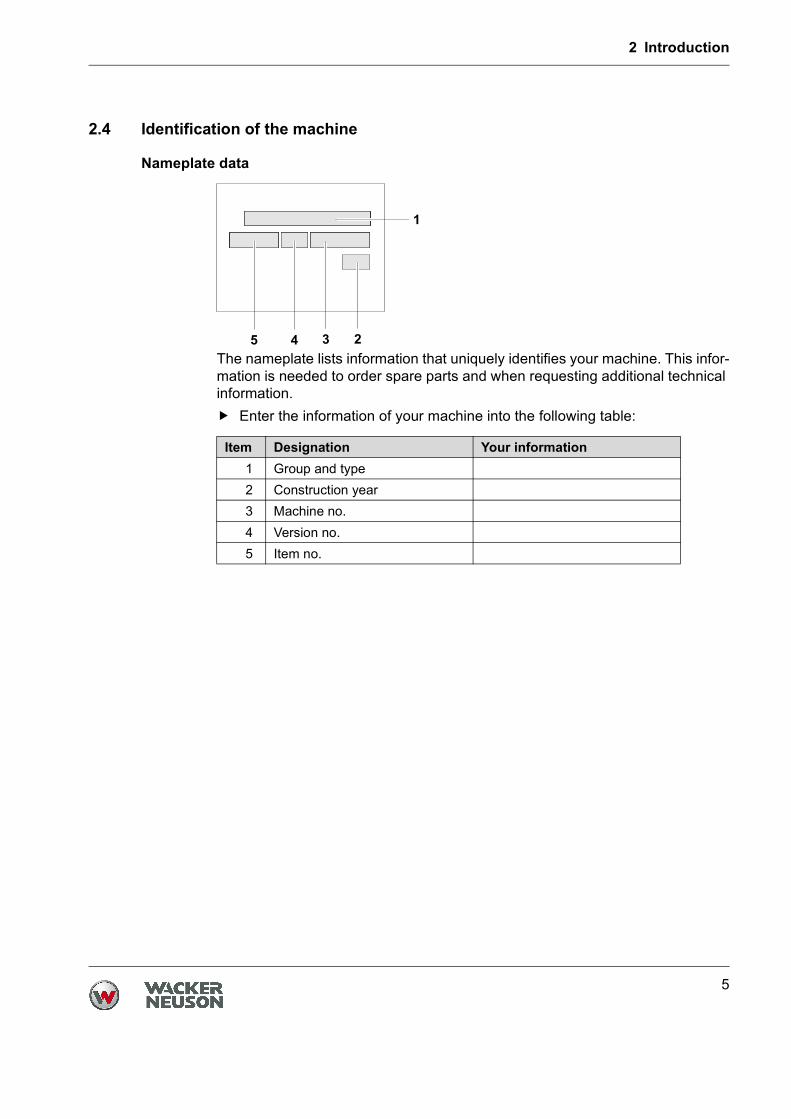
Nameplate data
The nameplate lists information that uniquely identifies your machine. This infor-mation is needed to order spare parts and when requesting additional technical information.
Enter the information of your machine into the following table:
Item Designation Your information1 Group and type2 Construction year3 Machine no.4 Version no.5 Item no.
3 Safety
6
3 Safety
3.1 Principle
State of the artThis machine has been constructed with state-of-the-art technology according to the recognized rules of safety. Nevertheless, when used improperly, dangers to the life and limb of the operator or to third persons or damage to the machine or other materials cannot be excluded.
State of the artThis machine has been constructed with state-of-the-art technology according tothe recognized rules of safety. Nevertheless, when used improperly, dangers tothe life and limb of the operator or to third persons or damage to the machine orother materials cannot be excluded.Proper useThe machine must only be used for the following purposes:
Cutting expansion joints in concrete, asphalt and screed.Cutting out damaged areas of concrete and asphalt.Straightening blacktops and concrete surfaces.Sawing off precast concrete parts.
The machine may only be used with cutting blades that are intended for use withthe machine and the material to be cut.The machine may not be used for the following purposes:
Cutting wood.Cutting plastics.Cutting materials that contain asbestos.
The machine may not be operated with blades, knives, brushes, etc.Its proper use also includes the observance of all instructions contained in thisoperator's manual as well as complying with the required service andmaintenance instructions.Any other use is regarded as improper. Any damage resulting from improper usewill void the warranty and the liability on behalf of the manufacturer. The operatorassumes full responsibility.
3 Safety
7
Structural modificationsNever attempt to modify the machine without the written permission of the manufacturer. To do so will endanger your safety and the safety of other people! In addition, this will void the warranty and the liability on behalf of the manufacturer.Especially the following are cases of structural modifications:
Opening the machine and the permanent removal of components from Wacker Neuson.Installing new components which are not from Wacker Neuson and not equivalent to the original parts in design and quality.Installation of accessories which are not from Wacker Neuson.
It is no problem to install spare parts from Wacker Neuson.It is no problem to install accessories that are available in the Wacker Neuson product range of your machine. Please refer to the installation regulations in this operator's manual.
Requirements for operationThe ability to operate the machine safely requires:
Proper transport, storage and setup.Careful operation.Careful service and maintenance.
OperationOperate the machine only as intended and only when in proper working condition.Operate the machine in a safety-conscious manner with all safety devices attached and enabled. Do not modify or disable any safety devices.Before starting operation, check that all control and safety devices are functioning properly.Never operate the machine in a potentially explosive environment.
SupervisionNever leave the machine running unattended!
MaintenanceRegular maintenance work is required in order for the machine to operate properly and reliably over time. Failure to perform adequate maintenance reduces the safety of the machine.
Strictly observe the prescribed maintenance intervals.Do not use the machine if it requires maintenance or repairs.
3 Safety
8
MalfunctionsIf you detect a malfunction, you must shut down and secure the machine immediately.Eliminate the malfunctions that impair safety immediately!Have damaged or defective components replaced immediately!For further information, refer to chapter Troubleshooting.
Spare parts, accessoriesUse only spare parts from Wacker Neuson or such that are equivalent to the original parts in design and quality.Only use accessories from Wacker Neuson.Non-compliance will exempt the manufacturer from all liability.
Exclusion of liabilityWacker Neuson will refuse to accept liability for injuries to persons or for damage to materials in the following cases:
Structural modifications.Improper use.Failure to comply with this operator's manual.Improper handling.Using of spare parts which are not from Wacker Neuson and not equivalent to the original parts in design and quality.Using of accessories which are not from Wacker Neuson.
Operator's manualAlways keep the operator's manual near the machine or near the worksite for quick reference. If you have misplaced the operator's manual or require an additional copy, contact your Wacker Neuson representative or download the operator's manual from the Internet (www.wackerneuson.com).Always hand over this operator's manual to other operators or to the future owner of the machine.
Country-specific regulationsObserve the country-specific regulations, standards and guidelines in reference to accident prevention and environmental safety, for example those pertaining to hazardous materials and wearing protective gear.Complement the operator's manual with additional instructions taking into account the operational, regulatory, national or generally applicable safety guidelines.
3 Safety
9
Operator's controlsAlways keep the operator's controls of the machine dry, clean and free of oil or grease.Operating elements such as ON/OFF switch, throttle levers etc. may not be locked, manipulated or changed without authorization.
Checking for signs of damageInspect the machine when it is switched off for any signs of damage at least once per work shift.Do not operate the machine if there is visible damage or defects.Have any damage or defects eliminated immediately.
3.2 Qualification of the operating personnel
Operator qualificationsOnly trained personnel are permitted to start and operate the machine. The following rules also apply:
You are at least 18 years of age.You are physically and mentally fit.You have received instruction on how to independently operate the machine.You have received instruction in the proper use of the machine.You are familiar with required safety devices.You are authorized to start machines and systems in accordance with the standards governing safety.Your company or the operator has assigned you to work independently with this machine.
Incorrect operationIncorrect operation or misuse by untrained personnel can endanger the health and safety of the operator or third persons and also cause machine and material damage.
Operating company responsibilitiesThe operating company must make the operator's manual available to the operator and ensure that the operator has read and understood it.
3 Safety
10
Work recommendationsPlease observe the recommendations below:
Work only if you are in a good physical condition.Work attentively, particularly as you finish.Do not operate the machine when you are tired.Carry out all work calmly, circumspectly and carefully.Never operate the machine under the influence of alcohol, drugs or medication. This can impair your vision, reactions and your judgment.Work in a manner that does not endanger others.
Ensure that no persons or animals are within the danger zone.
3.3 Protective gear
Work clothingClothing should be appropriate, i.e. should be close-fitting but not restrict your movement.When on construction sites, do not wear long hair loosely, loose clothing or je-welry including rings. These objects can easily get caught or be drawn in by mo-ving machine parts.Only wear clothing made of material that is not easily flammable.
Personal protective gearWear personal protective gear to avoid injuries or health hazards:
Non-skid, hard-toed shoes.Work gloves made of durable material.Overalls made of durable material.Hard hat.Ear protection.Face protection.Eye protection.Breathing protection in the case of dusty ambient air.
Ear protectionThis machine generates noise that exceeds the country-specific permissible noi-se levels (individual rating level). It may therefore be necessary to wear ear pro-tection. You can find the exact value in the chapter Technical Data.When wearing ear protection while working, you must pay attention and exercise caution because your hearing is limited, e.g. in case someone screams or a sig-nal tone sounds.Wacker Neuson recommends that you always wear ear protection.
3 Safety
11
Breathing protectionIf a lot of dust is produced when cutting, always wear suitable breathing protec-tion.Use the water supply.
Provision of fire extinguishersEnsure that a fire extinguisher is always to hand on the worksite.
Do not exceed the daily usage limitThe machine generates noise.Observe the regulations which apply in your country and guidelines concerning the maximum daily service life of the machine.Always wear the prescribed safety clothing.Information about the noise levels produced by the machine can be found in the Technical Data chapter.
3.4 Transport
Switching off the machineBefore you transport the machine, it must be switched off, and the engine must be given sufficient time to cool down.
Emptying the tankWacker Neuson recommends emptying the fuel tank before transport. Fuel could run out, e.g. if the machine is tilted.Observe the national safety guidelines and the hazardous materials regulations that apply to the respective means of transportation.
LiftingWhen lifting the machine, observe the following instructions:
Designate a skilled person to guide you for the lifting procedure.You must be able to see or hear this person.Use only suitable and certified hoisting gear, lifting tackle and load-bearing equipment with sufficient lifting capacities.Only use the attachment points described in the operator's manual.Attach the machine securely to the hoisting gear.Ensure that no one is nearby or under the machine.Do not climb onto the machine.Check the lifting strap on the machine for wear and damage.Before lifting, secure (loose) components with the relevant devices.Remove (loose) components before lifting.Remove the tool before lifting.
3 Safety
12
Loading the machineLoading ramps must be able to bear the load and be in a stable position.Make sure that no one can be endangered if the machine slips away or tips over or if machine parts suddenly move upward or downward.Put the operating controls and moving parts in their transport position.Secure the machine with load-securing straps so that it cannot tip over, fall down or slide away. Only use the attachment points described in the operator's manu-al.
Transport vehicleUse only suitable transport vehicles with sufficient load-carrying capacity and suitable tie-down lugs.
Transporting the machineSecure the machine on the transport device against tilting, falling or slipping.Only use the lashing points listed in the operating instructions.Also observe the country-specific regulations, standards and guidelines.
RestartingMachines, machine parts, accessories or tools that were detached for transport purposes must be re-mounted and fastened before restarting.Only operate in accordance with the operating instructions.
3.5 Operating safety
Explosible environmentNever operate the machine in a potentially explosive environment.
Work environmentFamiliarize yourself with your work environment before you start work. This in-cludes e.g. the following items:
Obstacles in the work and traffic area.Load-bearing capacity of the ground.The measures needed to cordon off the construction site from public traffic in particular.The measures needed to secure walls and ceilings.Options available in the event of an accident.
3 Safety
13
Safety in the work areaWhen working with the machine especially pay attention to the following points:
Electric lines or pipes in work area.Gas lines or water lines in the work area.Material becoming separated, dropping down or ejected. Make sure that you do not put other persons in danger.Pay maximum attention in the vicinity of drops or slopes. Risk of falling.Maintain a sufficient distance from flammable materials.
Checks before starting workCheck the following points before beginning work:
Condition of cutting blade.Safety devices.Switch and current-carrying lines for damage and corrosion.Tightness of the cutting blade.Machine settings.
Starting the machineObserve the safety information and warning notices located on the machine andin the operator's manual.Never attempt to start a machine that requires maintenance or repairs.Start the machine as described in the operator's manual.
Vertical stabilityAlways ensure that the machine is vertically stable and cannot tip over, roll or slide away.
Proper operator positionDo not leave the proper operator position while operating the machine.The intended operator position is at the controls behind the machine.
Caution with hot partsDo not touch the machine during or shortly after operation. Some parts can be-come very hot and can cause severe burns.
Caution with movable partsKeep your hands, feet and loose clothing away from moving or rotating machineparts. Parts of your body being pulled in or crushed can cause serious injuries.
3 Safety
14
Caution with toxic materialsSome materials may contain toxic chemicals which are released during demoli-tion. Therefore personal protective equipment must be worn to prevent inhalation of and skin contact with work dust.
No persons endangeredBe sure that no persons are endangered by flying or falling materials. Always work very attentively, and anticipate potential hazards.Make sure that people in the vicinity are at a sufficient distance from the machi-ne.
Do not use any starter spraysHighly flammable starter sprays pose a fire hazard.Do not use any starter sprays.Starter sprays are highly flammable and can cause backfiring and engine dama-ge.
Switching off the machineSwitch off the engine in the following situations:
Before breaks.If you are not using the machine.
Store the machine in such a way that it cannot tilt, fall or slip.
StorageStore the machine securely so that it cannot tilt, fall or slip.
Storage locationAfter operation, allow the machine to cool and then store it in a sealed-off, clean and dry location protected against frost and inaccessible to children.
VibrationsWhen manually operated machines are intensively used, long-term damage caused by vibrations cannot be precluded.Observe the relevant legal instructions and guidelines to minimize vibration stress.Details on vibration stress associated with the machine can be found in the chap-ter Technical Data.
3 Safety
15
3.6 Safety during the operation of combustion engines
Checking for signs of damageCheck the engine while switched off for leaks and cracks in the fuel line, tank and fuel cap at least once per work shift.Do not operate the machine if there is visible damage or defects.Have any damage or defects eliminated immediately.
Dangers during operationCombustion engines can be dangerous, particularly during operation and when refueling.Read and follow all safety instructions. Otherwise there is a risk of personal injuryand/or damage to property!Do not start the engine near spilt fuel or if you smell fuel – this may cause an ex-plosion!
Remove the machine from such areas.Remove the spilt fuel immediately!
Do not change the engine speedDo not change the preset engine speed, as this may cause engine damage.You may only change the idle speed. The idle speed must be set such that the cutting blade does not rotate while the engine is idling.
Preventing firesOpen flames and smoking are strictly prohibited in the immediate vicinity of themachine.Make sure that waste, such as paper, dry leaves or grass do not accumulatearound the exhaust muffler. The waste materials may ignite.
3 Safety
16
Safety precautions when refuelingPlease observe the following safety-relevant instructions when refueling:
Do not refuel near open flames.Do not smoke.Turn off the engine before refueling and allow it to cool down.Refuel in a well-ventilated environment.Wear fuel-proof protective gloves and, if there is the possibility of spraying, protective goggles and clothing.Do not inhale fuel vapors.Avoid skin and eye contact with fuel.For refueling, use clean tools such as a hopper.Do not spill fuel, especially onto hot parts.Remove any spilt fuel immediately.Use the correct fuel grade.Do not mix fuel with other liquids.Fill the tank only up to the maximum marking. If there is no maximum mar-king, do not fill up the tank completely.Lock the fuel cap securely after refueling.
Operation in closed roomsIn closed or partially closed rooms such as tunnels, drifts or deep trenches, ensu-re sufficient ventilation and extraction by, for example, providing a powerful ex-haust air fan.Danger of poisoning! Do not inhale exhaust fumes. They contain toxic carbon monoxide that can lead to unconsciousness or death.
Caution with hot partsDo not touch any hot parts such as the engine block or exhaust muffler during operation or directly afterwards. These parts can become very hot and cause se-vere burns.
Shutting off the fuel tapWhen the machine stops, shut off the fuel tap.
Cleaning the engineClean the engine when it is cool to remove any dirt.Do not use gasoline or solvents. Danger of explosion!
Health hazard due to exhaust fumesWarningThe engine's exhaust fumes contain chemicals which are known to the State of California to cause cancer, congenital defects or other reproductive anomalies.
3 Safety
17
Notes on the EPA engineCautionThis machine is equipped with an EPA-certified engine.Modifying the engine speed influences the EPA certification and emission. The engine may only be set by a skilled technician.For more detailed information, contact your nearest engine or Wacker Neuson representative.
3.7 Safety during floor saw operation
Belt guardNever operate the machine without a belt guard!Exposed belts and belt pulleys are dangerous and can cause serious injuries if they pull in any part of your body or if parts are ejected.
Danger of falling overOperate the machine so that it cannot tip over or fall down from bordered areas, edges and steps.
Cutting blade guardNever operate the machine without a cutting blade guard.The cutting blade guard performs the following functions:
Protects the operator from the rotating cutting blade.Diverts workpiece particles and sparks or chips from a damaged cutting bla-de away from the operator.
Only operate the machine when the cutting blade guard is folded down.Make sure that the cutting blade guard and its limit stops are not damaged or worn.
Wet-cuttingUse a water sprayer when dust formation is excessive, e.g. when cutting conc-rete or stone.Only use cutting blades that are suitable for wet cutting.Before ending the wet cutting process, allow the cutting blade to run without the water sprayer until it is dry.
Not exceeding the maximum tilt positionDo not exceed the maximum tilt position (see the description in the Maximum permissible tilt chapter).Only operate the machine at maximum tilt for short periods of time.
If you exceed the maximum tilt, the engine lubrication system will fail and thus inevitably damage important engine parts.
3 Safety
18
Notes regarding work methodsFold down the protective hood fully. The protective hood can catch material flung away from the work area and divert it away from the operator.Particularly when starting the engine you have to make sure that the cutting blade does not come into contact with anything.Always operate the machine at full throttle even when first placing it into the cut.When first placing the the cutting blade into the cut, set it slowly onto the ma-terial. Excessive pressure can damage the cutting blade.Move the machine in a straight line together with the cutting blade. Pressure from the side can damage the cutting blade.Avoid cutting tight curves.On sloping carriageways and surfaces, pressure must not be applied to the side of the blade.Never exceed the maximum speed (printed on cutting blade).
Removing foreign objects before cuttingBefore cutting, remove foreign objects such as nails, etc. from the cutting area.
Cutting various materialsDo not process loose materials (e.g. paving stones).Do not cut into the gravel area using diamond-edged cutting blades.When cutting on the edge of the track or when cutting two different materials (cutting in the joint area), uneven wear is possible.
Do not touch a rotating cutting bladeNever touch a rotating cutting blade with your hand or any other body part.Danger of severe injury.
Pay attention and exercise caution when working with ear protectionWhen wearing ear protection you must pay attention and exercise caution be-cause your hearing is limited, e.g. in case someone screams or a signal tone sounds.
Danger of fire due to sparksDanger of fire due to hot workpiece particles flung away from the work area.
Do not work near flammable materials.Only wear clothing made of material that is not easily flammable.
3 Safety
19
Notes regarding cutting bladesThe cutting blade must be suitable for use with the cut-off saw.The cutting blade must be suitable for the material to be cut.The speed allowed for the cutting blade must be the same as or higher than the maximum machine spindle speed.Mount the cutting blade such that its rotation direction is the same as that of the machine.Only use cutting blades with permissible cutting blade diameters.When using cutting blades with a hole diameter greater than the machine shaft, use the suitable adapter ring.Only use undamaged cutting blades.Ensure that you also follow the instructions of the cutting blade manufacturer.Do not use cutting blades that have fallen.Change the cutting blade only when the engine has been turned off.Always tighten the cutting blade with the specified torque.Test the new cutting blade for approx. 1 min at maximum speed (without cut-ting).Only use cutting blades with use-by dates that have not expired.When storing cutting blades, always lay them flat in an area that is protected from frost.
3.8 Maintenance
Maintenance workService and maintenance work must only be carried out to the extent described in these operating instructions. All other procedures must be performed by your Wacker Neuson representative.For further information, refer to chapter Maintenance.It is not permitted to tilt the machine for maintenance work.
Switching off the engineBefore carrying out care or maintenance work, switch off the engine and allow it to cool down.For gasoline powered engines, you must pull off the spark plug cap.
Checking the ignition systemCaution: the electronic ignition generates a very high voltage.
Disconnecting the batteryFor machines with electric starter, you must disconnect the battery before wor-king on the electronic parts.
3 Safety
20
Working on the batteryAlways take the following safety measures when working with the battery:
No fire, sparks, or smoking while working with batteries.Batteries contain corrosive acid. Use acid-proof protective gloves and protec-tive goggles when working with batteries.Avoid short circuits due to improper connection or bypassing with tools.Disconnect the negative terminal first when disconnecting the battery.Connect the positive terminal first when connecting the battery.Re-fasten terminal covers after connecting the battery.
Handling operating fluids safelyObserve the following points when handling operating fluids, e.g. fuels, oils,greases, coolants etc.:
Always wear personal safety clothing.Avoid skin and eye contact with operating fluids.Do not inhale or swallow operating fluids.In particular, avoid contact with hot operating fluids. Burn and scalding ha-zard.Dispose of replaced or spilled operating fluids according to the applicable re-gulations for environmental protection.If operating fluids escape from the machine, cease operation of the machine and have it repaired immediately by your Wacker Neuson representative.
Assembling safety devicesIf it was necessary to dismantle safety devices, they must be reassembled and checked immediately after completing maintenance work.Always tighten loosened screw connections, complying with prescribed starting torque.
CleaningAlways keep the machine clean and be sure to clean it each time you have fini-shed using it.Do not use gasoline or solvents. Danger of explosion!Do not use high pressure washers. Permeating water can damage the machine.When electrical equipment is present, this can pose a serious injury risk from electric shocks.
3 Safety
21
3.9 Safety devices
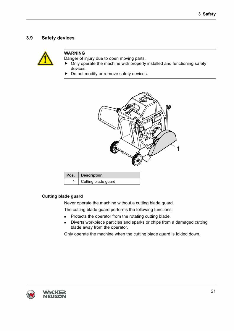
Cutting blade guardNever operate the machine without a cutting blade guard.The cutting blade guard performs the following functions:
Protects the operator from the rotating cutting blade.Diverts workpiece particles and sparks or chips from a damaged cutting blade away from the operator.
Only operate the machine when the cutting blade guard is folded down.
WARNINGDanger of injury due to open moving parts.
Only operate the machine with properly installed and functioning safety devices.Do not modify or remove safety devices.
Pos. Description1 Cutting blade guard
4 Safety and information labels
22
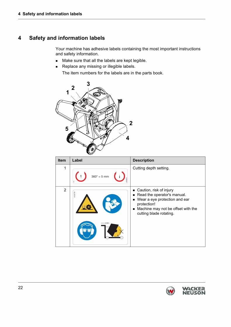
4 Safety and information labels
Your machine has adhesive labels containing the most important instructions and safety information.
Make sure that all the labels are kept legible.Replace any missing or illegible labels.The item numbers for the labels are in the parts book.
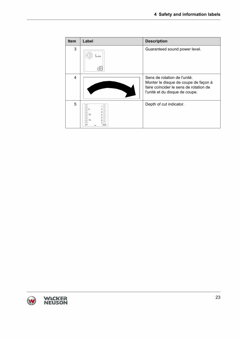
Item Label Description
1 Cutting depth setting.
2 Caution, risk of injuryRead the operator's manual.Wear a eye protection and ear protection!Machine may not be offset with the cutting blade rotating.
SE
S
00
58
870
360° = 5 mm
01
25
77
8
4 Safety and information labels
23
3 Guaranteed sound power level.
4 Sens de rotation de l'unité.Monter le disque de coupe de façon à faire coïncider le sens de rotation de l'unité et du disque de coupe.
5 Depth of cut indicator.
Item Label Description
5 Technical data
24
5 Technical data
Machine
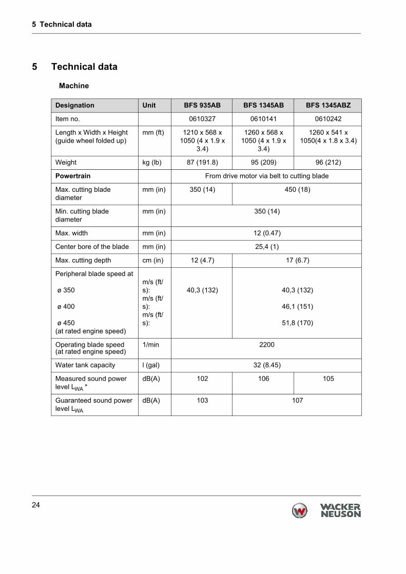
Designation Unit BFS 935AB BFS 1345AB BFS 1345ABZ
Item no. 0610327 0610141 0610242
Length x Width x Height(guide wheel folded up)
mm (ft) 1210 x 568 x 1050 (4 x 1.9 x
3.4)
1260 x 568 x 1050 (4 x 1.9 x
3.4)
1260 x 541 x 1050(4 x 1.8 x 3.4)
Weight kg (lb) 87 (191.8) 95 (209) 96 (212)
Powertrain From drive motor via belt to cutting blade
Max. cutting blade diameter
mm (in) 350 (14) 450 (18)
Min. cutting blade diameter
mm (in) 350 (14)
Max. width mm (in) 12 (0.47)
Center bore of the blade mm (in) 25,4 (1)
Max. cutting depth cm (in) 12 (4.7) 17 (6.7)
Peripheral blade speed at
ø 350
ø 400
ø 450(at rated engine speed)
m/s (ft/s):m/s (ft/s):m/s (ft/s):
40,3 (132) 40,3 (132)
46,1 (151)
51,8 (170)
Operating blade speed(at rated engine speed)
1/min 2200
Water tank capacity l (gal) 32 (8.45)
Measured sound power level LWA *
dB(A) 102 106 105
Guaranteed sound power level LWA
dB(A) 103 107

5 Technical data
25
Sound pressure level LpA at operator's station *
dB(A) 94 98
Total vibration value of the acceleration ahv *
m/s2
(ft/s2)8,4 (27.5) 6,2 (20.3)
Uncertainty of measurement of the vibration total value of the acceleration ahv
m/s2
(ft/s2)1,5 (4.9)
* According to DIN EN ISO 5349
Designation Unit BFS 935AB BFS 1345AB BFS 1345ABZ
5 Technical data
26
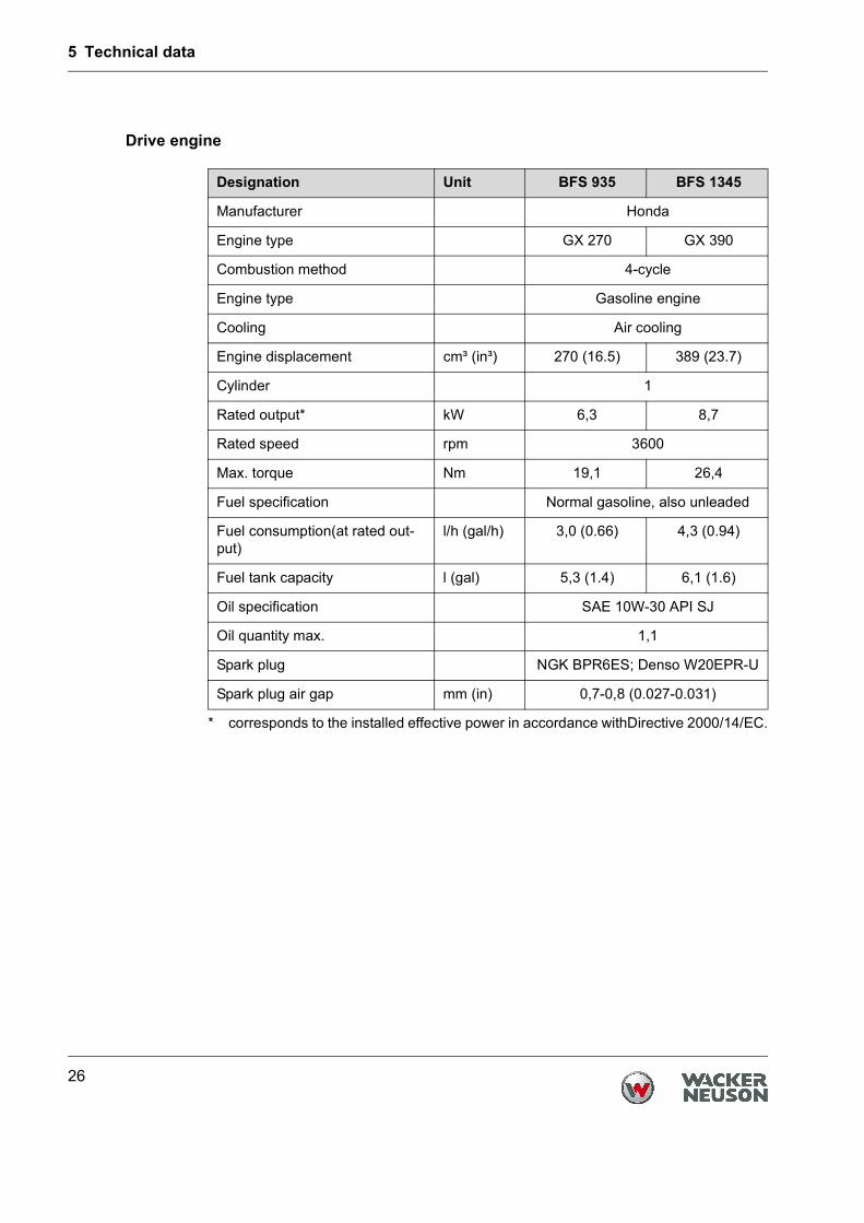
Drive engine
Designation Unit BFS 935 BFS 1345
Manufacturer Honda
Engine type GX 270 GX 390
Combustion method 4-cycle
Engine type Gasoline engine
Cooling Air cooling
Engine displacement cm³ (in³) 270 (16.5) 389 (23.7)
Cylinder 1
Rated output*
* corresponds to the installed effective power in accordance withDirective 2000/14/EC.
kW 6,3 8,7
Rated speed rpm 3600
Max. torque Nm 19,1 26,4
Fuel specification Normal gasoline, also unleaded
Fuel consumption(at rated out-put)
l/h (gal/h) 3,0 (0.66) 4,3 (0.94)
Fuel tank capacity l (gal) 5,3 (1.4) 6,1 (1.6)
Oil specification SAE 10W-30 API SJ
Oil quantity max. 1,1
Spark plug NGK BPR6ES; Denso W20EPR-U
Spark plug air gap mm (in) 0,7-0,8 (0.027-0.031)
Description
T01067en.fm 27
1. Description
1.1 Application
∗ Cutting expansion joints in concrete and asphalt surfaces.∗ Repair work on streets, e.g. cutting out damaged areas in asphalt and
concrete.∗ Straightening blacktops and concrete surfaces.∗ For demolition jobs and refurbishment of old buildings.∗ Sawing off precast concrete parts.∗ Expansion joints and installation channels in floors.∗ Laying induction loops and cables in signal installations.
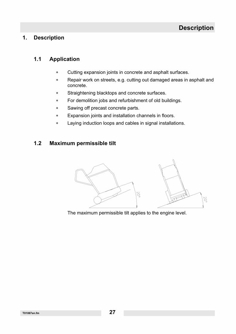
1.2 Maximum permissible tilt
The maximum permissible tilt applies to the engine level.

Description
T01067en.fm 28
1.3 Functional description
The floor saw must only be operated in a forward direction (see arrow).The drive motor (1) attached to the frame drives the cutting blade viathe belt (2).The cutting blade can be infinitely adjusted by means of a crankhandle (3), 1 turn corresponds to a cutting depth adjustment of 5 mm.The cutting blade guard (4) can be swiveled upwards to make it easierto assemble and disassemble the cutting blade.Furthermore, the cutting blade guard can be connected with the watertank by means of a hose (5) and an adapter.Wetting the cutting blade with water prevents dust from developing.The adapter on the water hose allows the connection of an externalwater supply.The drive motor speed can be infinitely adjusted by means of the gasthrottle lever (6), whereby the optimum cutting blade speed is reachedwhen the drive motor is operated at full throttle.To facilitate the starting procedure, the drive motor is equipped with achoke.
Description
T01067en.fm 29
1.4 General instructions for use for diamond-edged cutting blades
∗ Never use a cutting blade with a larger diameter than necessary in or-der to cut a certain depth.
∗ If the cutting blade comes to a standstill, remove it from the cut beforestarting the machine again. If the cutting blade comes to a standstill inthe cut, check whether the belt is tightened adequately. Check the ten-sion screw and make sure that it is tightened properly.
∗ Cut in a straight line. Mark the cutting line clearly in such a way that theoperational personnel can follow it easily. This is to ensure that thefloor saw machine does not need to be redirected from one side to theother (avoid cutting tight curves).
∗ Sufficient drive power is essential! When cutting, work at full throttle.∗ Caution on steep tracks and levels! The machine must not exert lateral
force against the blade.∗ Never exceed the maximum speeds (imprinted on cutting blade)!∗ Use a suitable diamond-edged cutting blade for the material to be cut
(asphalt, concrete ...). Wacker Neuson offers an extensive range of di-amond-edged cutting blades in different qualities.
∗ Do not cut into the gravel area using diamond-edged cutting blades.When cutting on the edge of the track or when cutting two different ma-terials (cutting in the joint area), uneven wear is possible. Check care-fully for irregularities (reinforcements etc.) in the material to beprocessed. These can overload the cutting blade very quickly. Whenstarting cutting operations, work carefully and with a low down speed.
∗ Do not process loose materials (e. g. paving stones).
Transport to the worksite
T01111en.fm 30
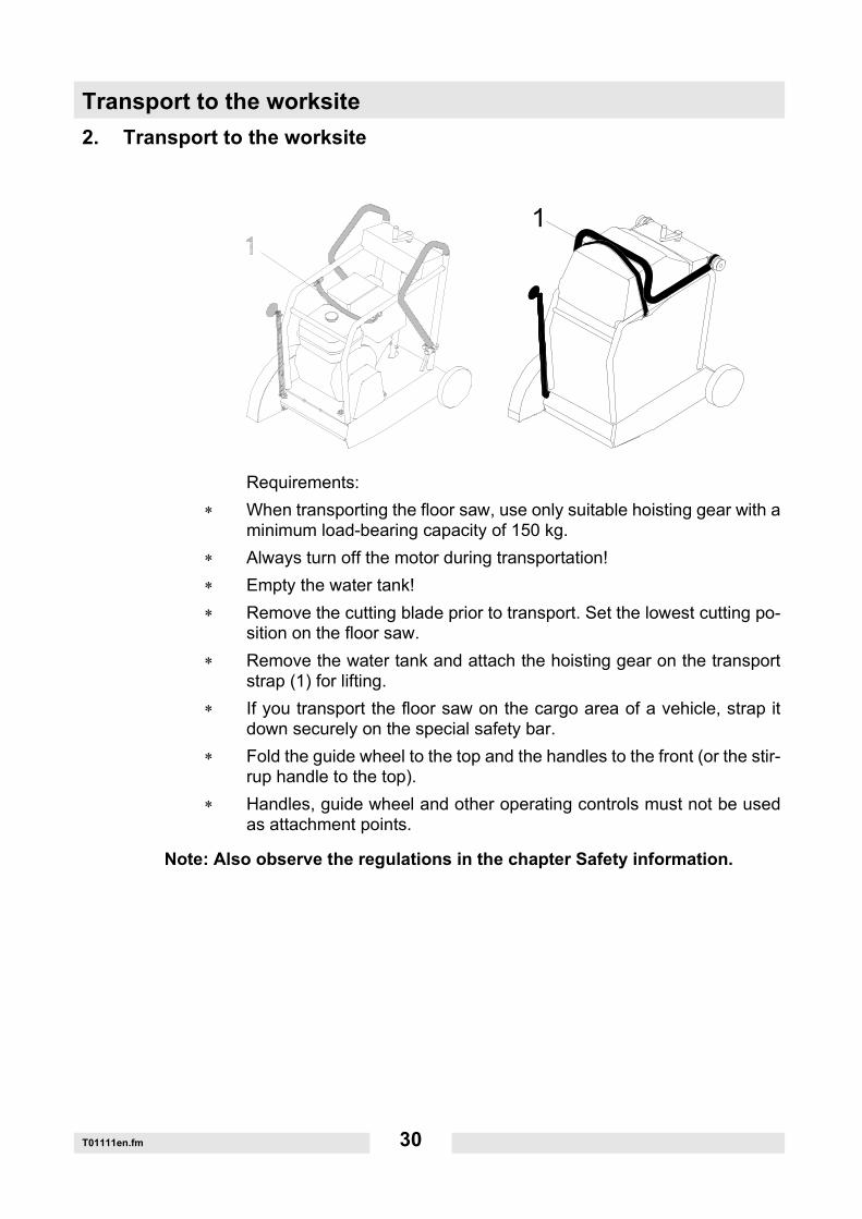
2. Transport to the worksite
Requirements:∗ When transporting the floor saw, use only suitable hoisting gear with a
minimum load-bearing capacity of 150 kg.∗ Always turn off the motor during transportation!∗ Empty the water tank!∗ Remove the cutting blade prior to transport. Set the lowest cutting po-
sition on the floor saw.∗ Remove the water tank and attach the hoisting gear on the transport
strap (1) for lifting.∗ If you transport the floor saw on the cargo area of a vehicle, strap it
down securely on the special safety bar.∗ Fold the guide wheel to the top and the handles to the front (or the stir-
rup handle to the top).∗ Handles, guide wheel and other operating controls must not be used
as attachment points.
Note: Also observe the regulations in the chapter Safety information.
Operation
T01109en.fm 31
3. Operation
3.1 Adjusting the handle
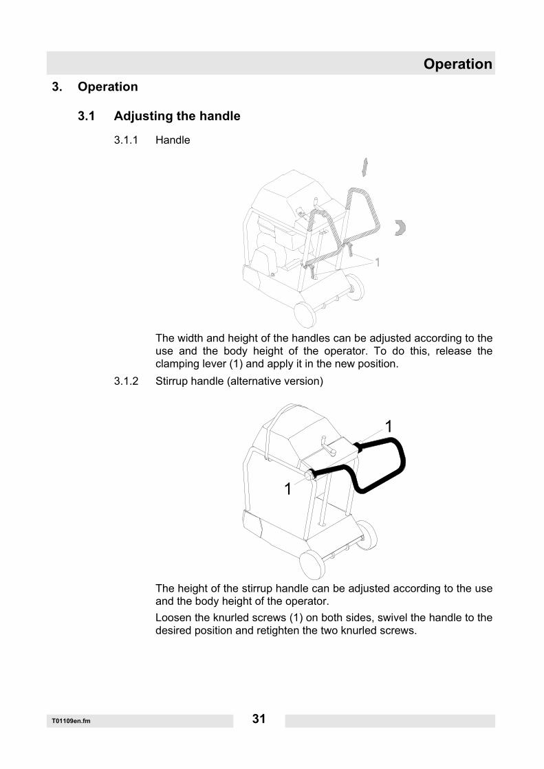
3.1.1 Handle
The width and height of the handles can be adjusted according to theuse and the body height of the operator. To do this, release theclamping lever (1) and apply it in the new position.
3.1.2 Stirrup handle (alternative version)
The height of the stirrup handle can be adjusted according to the useand the body height of the operator.Loosen the knurled screws (1) on both sides, swivel the handle to thedesired position and retighten the two knurled screws.
Operation
T01109en.fm 32
3.2 Adjusting the guide wheel
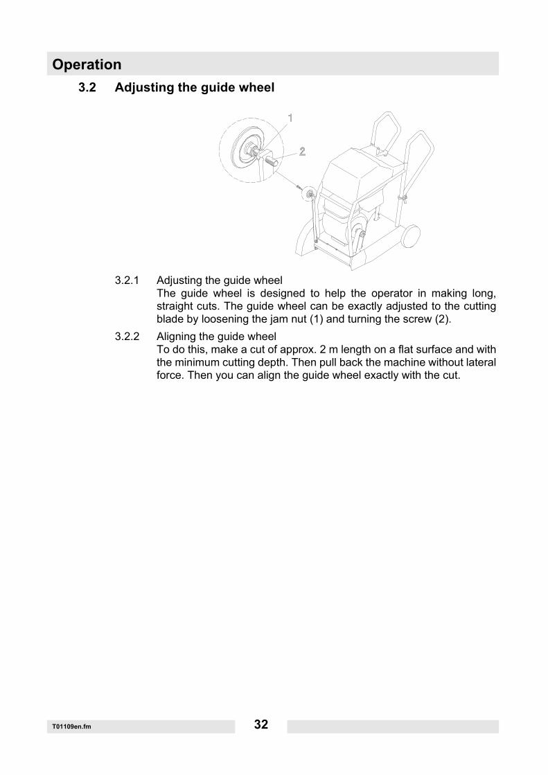
3.2.1 Adjusting the guide wheelThe guide wheel is designed to help the operator in making long,straight cuts. The guide wheel can be exactly adjusted to the cuttingblade by loosening the jam nut (1) and turning the screw (2).
3.2.2 Aligning the guide wheelTo do this, make a cut of approx. 2 m length on a flat surface and withthe minimum cutting depth. Then pull back the machine without lateralforce. Then you can align the guide wheel exactly with the cut.
Operation
T01109en.fm 33
3.3 Cutting depth setting
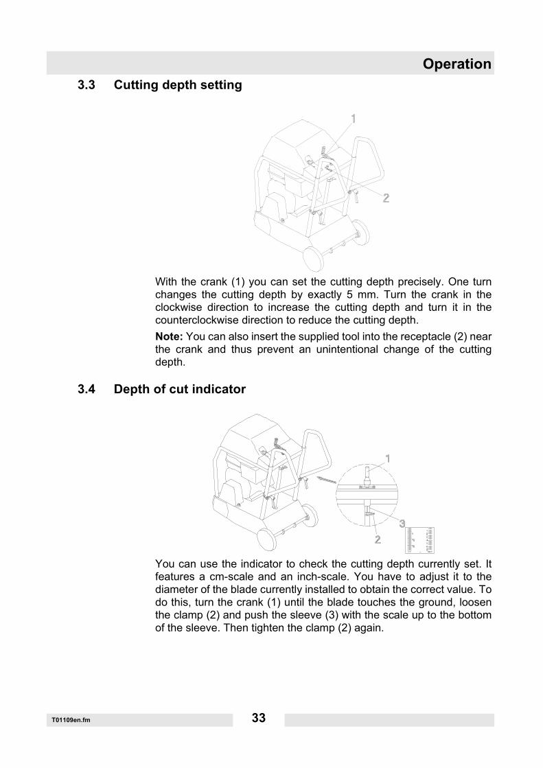
With the crank (1) you can set the cutting depth precisely. One turnchanges the cutting depth by exactly 5 mm. Turn the crank in theclockwise direction to increase the cutting depth and turn it in thecounterclockwise direction to reduce the cutting depth.Note: You can also insert the supplied tool into the receptacle (2) nearthe crank and thus prevent an unintentional change of the cuttingdepth.
3.4 Depth of cut indicator
You can use the indicator to check the cutting depth currently set. Itfeatures a cm-scale and an inch-scale. You have to adjust it to thediameter of the blade currently installed to obtain the correct value. Todo this, turn the crank (1) until the blade touches the ground, loosenthe clamp (2) and push the sleeve (3) with the scale up to the bottomof the sleeve. Then tighten the clamp (2) again.

Operation
T01109en.fm 34
3.5 Water tank
The floor saw features an integrated, removable water tank (1).To fit the water tank, attach the retaining clamp (2) and tighten it withthe strap (3).To remove the water tank or to attach an external water supply, youcan disconnect the hose on two different spots (4).The amount of water can be regulated or stopped (5).
Note: You should remove the water tank if the machine is connected to anexternal water supply.

Operation
T01109en.fm 35
3.6 Parking brake
Integrated parking brakeThe machine features an integrated parking brake.The front wheels are automatically blocked in transport position(lowest cutting position without a cutting blade) or if the maximumcutting depth is exceeded.
Operation
T01109en.fm 36
3.7 Assembling the cutting blade
3.7.1 Checking a new cutting blade:∗ The blade type must be suitable for the material to be cut. Observe the
peripheral speed, refer to the "Technical data"!∗ The arbor diameter of the cutting blade must precisely fit the shaft to
ensure smooth blade running.∗ The cutting blade must be undamaged.
Observe the correct direction of rotation of the cutting blade! Thatmeans the rotational direction mark on the cutting blade mustcorrespond with the rotational direction mark on the cutting bladeguard.
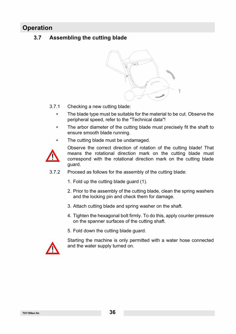
3.7.2 Proceed as follows for the assembly of the cutting blade:
1. Fold up the cutting blade guard (1).
2. Prior to the assembly of the cutting blade, clean the spring washersand the locking pin and check them for damage.
3. Attach cutting blade and spring washer on the shaft.
4. Tighten the hexagonal bolt firmly. To do this, apply counter pressureon the spanner surfaces of the cutting shaft.
5. Fold down the cutting blade guard.
Starting the machine is only permitted with a water hose connectedand the water supply turned on.
Operation
T01109en.fm 37
3.8 Disassembling the cutting blade
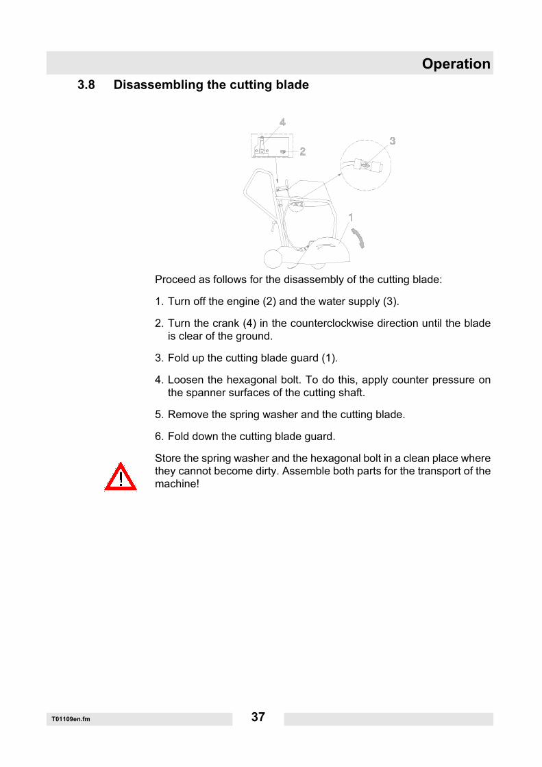
Proceed as follows for the disassembly of the cutting blade:
1. Turn off the engine (2) and the water supply (3).
2. Turn the crank (4) in the counterclockwise direction until the bladeis clear of the ground.
3. Fold up the cutting blade guard (1).
4. Loosen the hexagonal bolt. To do this, apply counter pressure onthe spanner surfaces of the cutting shaft.
5. Remove the spring washer and the cutting blade.
6. Fold down the cutting blade guard.
Store the spring washer and the hexagonal bolt in a clean place wherethey cannot become dirty. Assemble both parts for the transport of themachine!
Operation
T01109en.fm 38
3.9 Checking the motor before starting
3.9.1 Engine oilSwitch off the engine.Prior to checking the engine oil level or refilling engine oil, make surethat the engine bolting level is aligned horizontally.
∗ Remove the oil filler cap (oil level indicator).∗ If the oil level is below the lower filling mark on the dip stick, add suit-
able engine oil until the oil reaches the edge of the filler neck.∗ An oil change is required if the engine oil is dirty.∗ Only use high-quality engine oil, see chapter Technical Data.
The engine is automatically switched off when the oil level falls belowa specific level. If this is the case, the engine can only be started afterengine oil has been refilled.
3.9.2 FuelDo not smoke during refueling and make sure that there are no openflames or sparks in the immediate vicinity.
∗ Turn off the engine and open the fuel tank cap.∗ Only use leadfree fuel.∗ Close the fuel tap before the fuel tank is filled with fuel.∗ Always use the fuel filter when refilling fuel.∗ Wipe off any spilled fuel before starting the engine.
3.9.3 Air cleanerCheck if the air cleaner cartridges and the cyclone housing are cleanand in good condition. If needed, clean or replace the cartridges.
Operation
T01109en.fm 39
3.10 Starting the engine
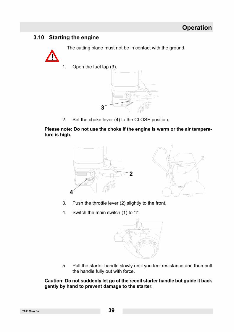
The cutting blade must not be in contact with the ground.
1. Open the fuel tap (3).
2. Set the choke lever (4) to the CLOSE position.
Please note: Do not use the choke if the engine is warm or the air tempera-ture is high.
3. Push the throttle lever (2) slightly to the front.
4. Switch the main switch (1) to "I".
5. Pull the starter handle slowly until you feel resistance and then pullthe handle fully out with force.
Caution: Do not suddenly let go of the recoil starter handle but guide it backgently by hand to prevent damage to the starter.
3
2
4
Operation
T01109en.fm 40
3.11 Operating the engine
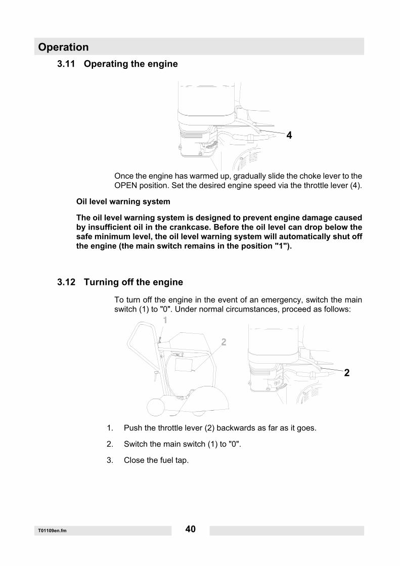
Once the engine has warmed up, gradually slide the choke lever to theOPEN position. Set the desired engine speed via the throttle lever (4).
Oil level warning system
The oil level warning system is designed to prevent engine damage causedby insufficient oil in the crankcase. Before the oil level can drop below thesafe minimum level, the oil level warning system will automatically shut offthe engine (the main switch remains in the position "1").
3.12 Turning off the engine
To turn off the engine in the event of an emergency, switch the mainswitch (1) to "0". Under normal circumstances, proceed as follows:
1. Push the throttle lever (2) backwards as far as it goes.
2. Switch the main switch (1) to "0".
3. Close the fuel tap.
4
2
Maintenance
T01072en.fm 41
4. Maintenance
4.1 Maintenance schedule
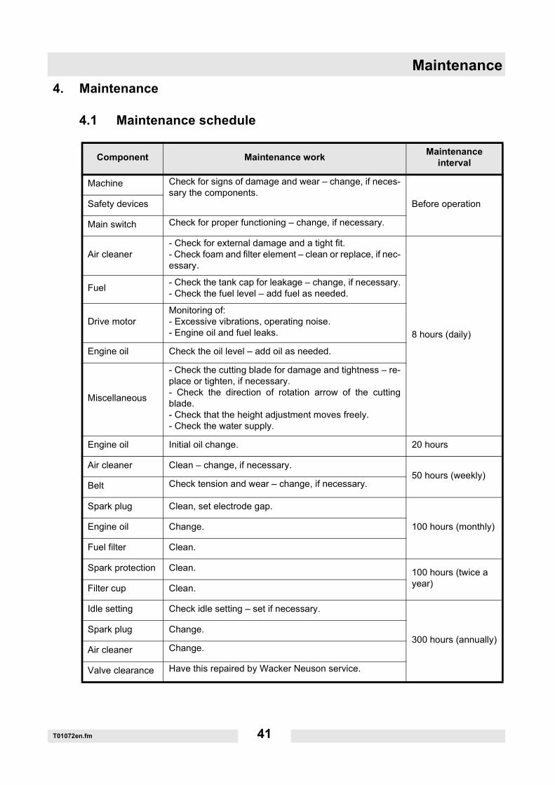
Component Maintenance work Maintenance interval
Machine Check for signs of damage and wear – change, if neces-sary the components.
Before operationSafety devices
Main switch Check for proper functioning – change, if necessary.
Air cleaner- Check for external damage and a tight fit.- Check foam and filter element – clean or replace, if nec-essary.
8 hours (daily)
Fuel - Check the tank cap for leakage – change, if necessary.- Check the fuel level – add fuel as needed.
Drive motorMonitoring of:- Excessive vibrations, operating noise.- Engine oil and fuel leaks.
Engine oil Check the oil level – add oil as needed.
Miscellaneous
- Check the cutting blade for damage and tightness – re-place or tighten, if necessary.- Check the direction of rotation arrow of the cuttingblade.- Check that the height adjustment moves freely. - Check the water supply.
Engine oil Initial oil change. 20 hours
Air cleaner Clean – change, if necessary.50 hours (weekly)
Belt Check tension and wear – change, if necessary.
Spark plug Clean, set electrode gap.
100 hours (monthly)Engine oil Change.
Fuel filter Clean.
Spark protection Clean. 100 hours (twice a year)Filter cup Clean.
Idle setting Check idle setting – set if necessary.
300 hours (annually)Spark plug Change.
Air cleaner Change.
Valve clearance Have this repaired by Wacker Neuson service.
Maintenance
T01072en.fm 42
4.2 Checking engine oil level
∗ Turn off the engine.∗ Align the engine bolting level horizontally.∗ Remove any dirt around the oil level dipstick.∗ Remove the oil level dipstick and wipe it with a clean, lint-free cloth.∗ Screw the oil level dipstick all the way back in and pull it out again.∗ Check: The motor oil level must be between the lower and upper
marks.∗ If necessary, pour new engine oil into the opening until the upper mark
is reached on the oil level dipstick (see chapter Technical data for oiltype).
∗ Screw in the oil level dipstick and tighten it by hand.
4.3 Changing the engine oil
The work area should be covered with a waterproof sheet to protect thefloor (protection of the environment).
∗ Align the engine bolting level horizontally.∗ Bring the engine to a hand warm temperature, either by letting it cool
down or running it until it is warm.∗ Turn off the engine.∗ Place a sufficiently large container under the oil drain hose to catch the
used oil.∗ Remove oil drain hose from the holder.∗ Remove any dirt around the locking screw.∗ Unscrew the cap nut.∗ Let the used oil drain out completely.
Avoid spilling oil. Remove any spilled oil immediately.
∗ Close oil drain hose with cap nut.∗ Attach oil drain hose to the holder.∗ Pour new engine oil (see chapter Technical data) into the opening of
the oil level dipstick until the upper mark is reached on the oil level dip-stick (see Checking engine oil level).
∗ Screw in the oil level dipstick and tighten it by hand.
Dispose of the used oil in accordance with the applicable regulations.
Maintenance
T01072en.fm 43
4.4 Cleaning the air cleaner
A dirty air cleaner obstructs the flow of air to the carburetor. To preventcarburetor malfunctions, clean the air cleaner on a regular basis. Cleanthe filter more frequently if the engine is operated in an extremely dustyenvironment.
Warning: Never use gasoline or cleaning solutions with a low flash point toclean the air cleaner cartridge. This could cause a fire or worse an explo-sion.
Caution: Never run the engine without an air cleaner. This leadsto undue engine wear.
1. Remove the wing nuts and the air cleaner cap. Take out the ele-ments and separate them. Check both elements for holes or tearsand replace them as needed.
2. Foam element: Wash out the element in warm soap water, rinse itand allow it to completely dry. If necessary, wash out the element ina cleaning solution with high flash point and allow it to dry.
3. Paper element: Tap the element lightly against a hard surface a fewtimes to loosen excess dirt. Never attempt to brush off the dirt, sincethis will rub the dirt into the fibers. Replace the paper element if it isvery dirty.
Cleaning the cyclone housing:If dirt accumulates in the cyclone housing, unscrew the three specialflat head screws and wipe the components or rinse them with water.Then completely dry off the components and assemble them carefully.
Caution:
∗ During the reassembly of the cyclone, make sure that the cloth of theair inlet fits properly into the groove of the preliminary filter cap.
∗ Install the air horn in the correct direction.
4.5 Cleaning the filter cup
Close the fuel tap. Remove the filter cup with the o-ring and wash it outwith non-combustible and low-flammable solvent. Allow it to complete-ly dry, then reinstall it and tighten it firmly. Open the fuel tap and checkfor leaks.
Maintenance
T01072en.fm 44
4.6 Idle setting
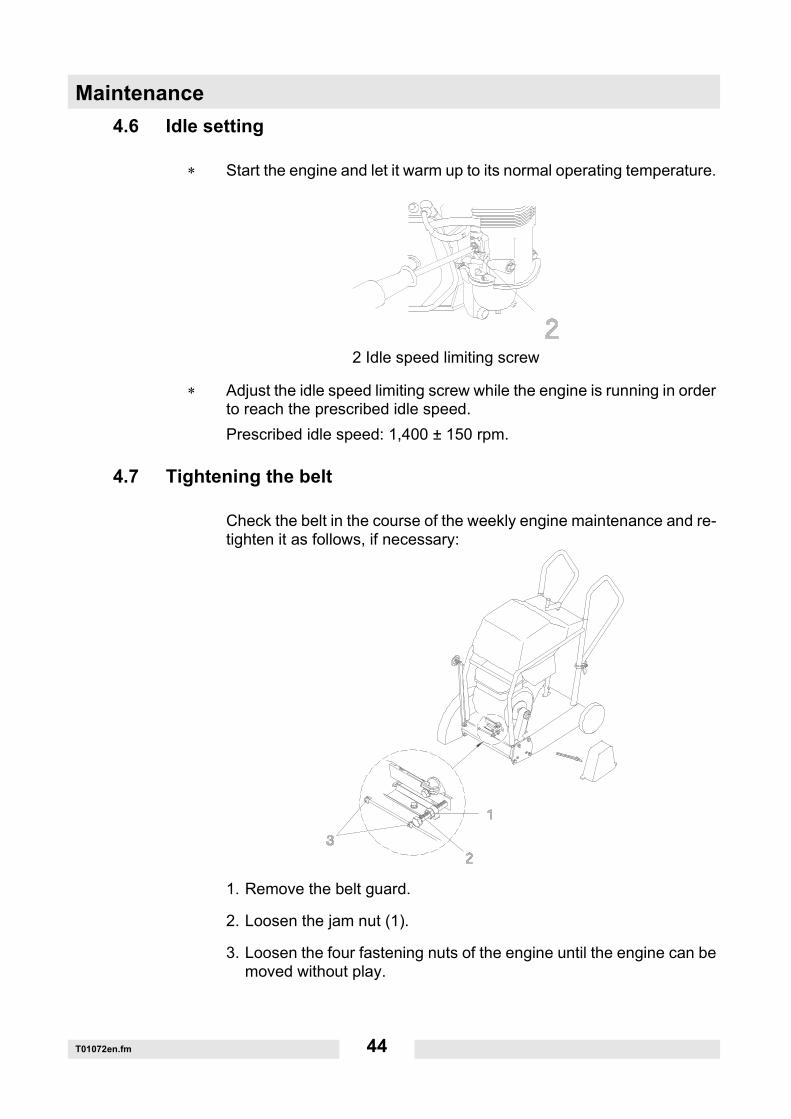
∗ Start the engine and let it warm up to its normal operating temperature.
∗ Adjust the idle speed limiting screw while the engine is running in orderto reach the prescribed idle speed.Prescribed idle speed: 1,400 ± 150 rpm.
4.7 Tightening the belt
Check the belt in the course of the weekly engine maintenance and re-tighten it as follows, if necessary:
1. Remove the belt guard.
2. Loosen the jam nut (1).
3. Loosen the four fastening nuts of the engine until the engine can bemoved without play.
2 Idle speed limiting screw
Maintenance
T01072en.fm 45
4. Tighten the belt with the tension screw (2). Belt tension 700 N (vibration frequency 98 Hz).
5. If necessary, correct the parallel alignment of the engine. As a first step, tighten a fastening nut of the engine and correct thealignment by means of the tension screw (2).
6. Tighten all fastening nuts of the engine as well as the jam nut (1).
7. Mount the belt guard.
Note: The frame is provided with two recesses (3) which can be used tomeasure the parallel alignment of the engine.
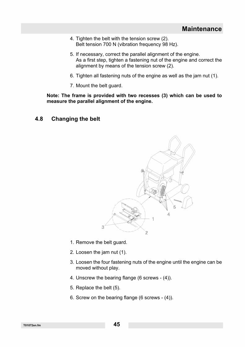
4.8 Changing the belt
1. Remove the belt guard.
2. Loosen the jam nut (1).
3. Loosen the four fastening nuts of the engine until the engine can bemoved without play.
4. Unscrew the bearing flange (6 screws - (4)).
5. Replace the belt (5).
6. Screw on the bearing flange (6 screws - (4)).
Maintenance
T01072en.fm 46
7. Tighten the belt with the tension screw (2). Belt tension 700 N (vibration frequency 98 Hz).
8. If necessary, correct the parallel alignment of the engine. As a first step, tighten a fastening nut of the engine and correct thealignment by means of the tension screw (2).
9. Tighten all fastening nuts of the engine as well as the jam nut (1).
10.Mount the belt guard.
Note: The frame is provided with two recesses (3) which can be used tomeasure the parallel alignment of the engine.
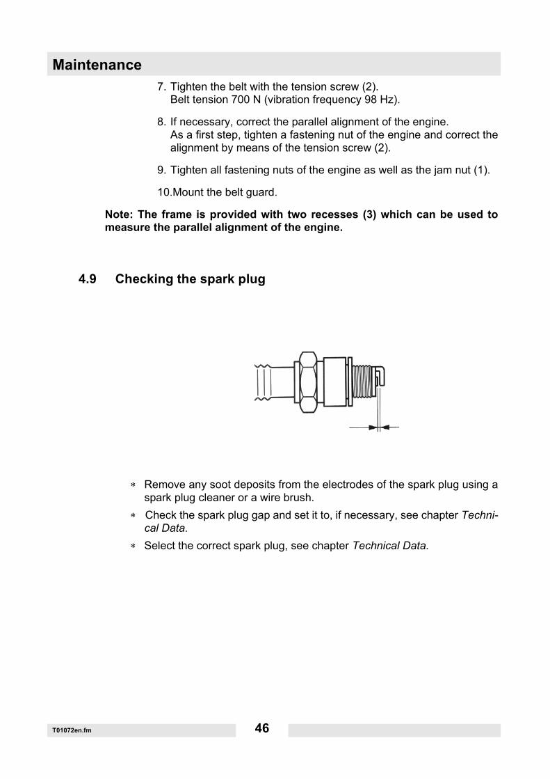
4.9 Checking the spark plug
∗ Remove any soot deposits from the electrodes of the spark plug using aspark plug cleaner or a wire brush.
∗ Check the spark plug gap and set it to, if necessary, see chapter Techni-cal Data.
∗ Select the correct spark plug, see chapter Technical Data.
6 Accessories
47
6 Accessories
There is a wide range of accessories available for the machine.For more information on the individual accessories, visit the following website: www.wackerneuson.com.
6.1 Parking brake (not for BFS...Z)
PrincipleThe parking brake secures the machine against rolling away by clamping a rear wheel with the foot lever.
Proper useThe parking brake may only be used to park the machine on the construction site and for storing the machine.The parking brake must not be used for the following:
Securing the machine when it is being transported.Securing the machine on slopes of more than 10°. The stability of the machine can no longer be guaranteed on slopes over 10°.Start the engine with the parking brake engaged so that the cutting blade cannot become wedged in the ground.
Performing preparations1. Switch off the machine.2. Park the machine so that it is stable and cannot tip, roll, slide or fall over.
WARNINGImproper handling can result in injury or serious material damage.
Read and follow all safety information of this operator's manual, see chapter Safety.
6 Accessories
48
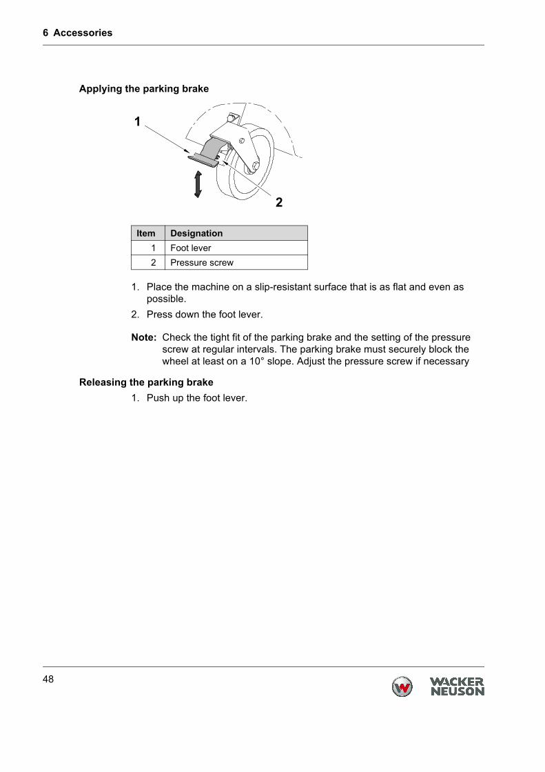
Applying the parking brake
1. Place the machine on a slip-resistant surface that is as flat and even as possible.
2. Press down the foot lever.
Note: Check the tight fit of the parking brake and the setting of the pressure screw at regular intervals. The parking brake must securely block the wheel at least on a 10° slope. Adjust the pressure screw if necessary
Releasing the parking brake1. Push up the foot lever.
Item Designation1 Foot lever2 Pressure screw
6 Accessories
49
6.2 Parking brake (for BFS...Z only)
PrincipleThe parking brake secures the machine against rolling away by jacking up the rear wheels on the parking brake. The latching element is used to hold the parking brake when it is released.
Proper useThe parking brake may only be used to park the machine on the construction site and for storing the machine.The parking brake must not be used for the following:
Securing the machine when it is being transported.Lifting or pulling the machine.Securing the machine on slopes of more than 10°. The stability of the machine can no longer be guaranteed on slopes over 10°.Start the engine with the parking brake engaged so that the cutting blade cannot become wedged in the ground.
Note: The machine should be jacked up for refueling. You must make sure that the machine is not subjected to any impacts.
Performing preparations1. Switch off the machine.2. Park the machine so that it is stable and cannot tip, roll, slide or fall over.
6 Accessories
50
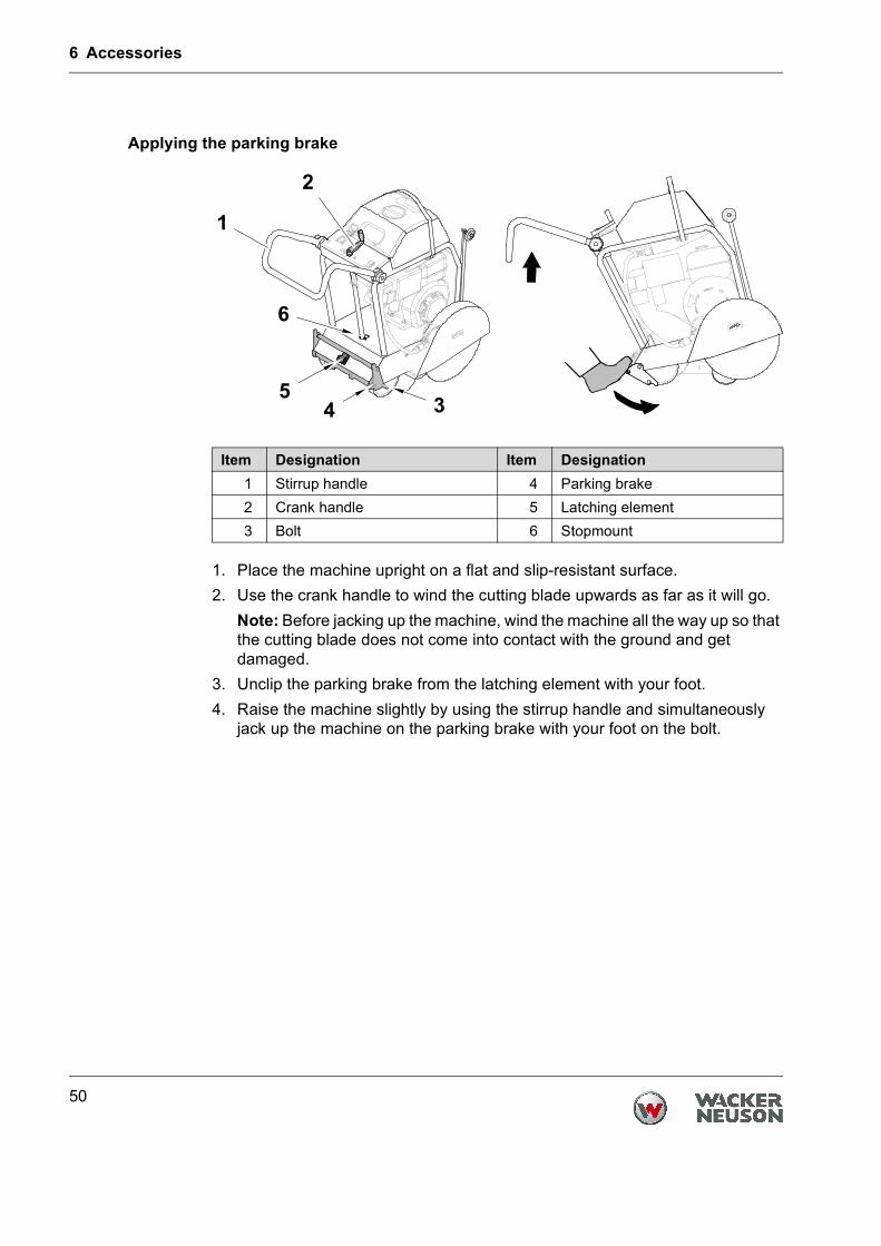
Applying the parking brake
1. Place the machine upright on a flat and slip-resistant surface.2. Use the crank handle to wind the cutting blade upwards as far as it will go.
Note: Before jacking up the machine, wind the machine all the way up so that the cutting blade does not come into contact with the ground and get damaged.
3. Unclip the parking brake from the latching element with your foot.4. Raise the machine slightly by using the stirrup handle and simultaneously
jack up the machine on the parking brake with your foot on the bolt.
Item Designation Item Designation1 Stirrup handle 4 Parking brake2 Crank handle 5 Latching element3 Bolt 6 Stopmount
6 Accessories
51
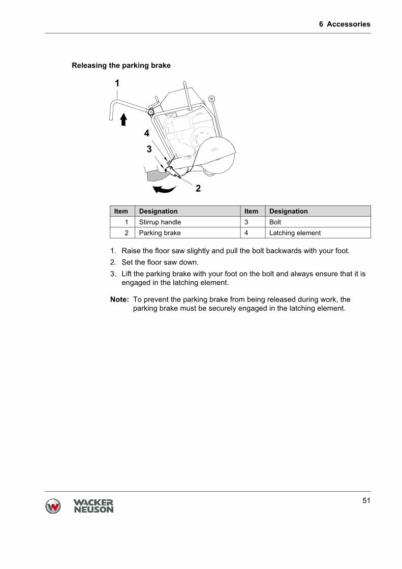
Releasing the parking brake
1. Raise the floor saw slightly and pull the bolt backwards with your foot.2. Set the floor saw down.3. Lift the parking brake with your foot on the bolt and always ensure that it is
engaged in the latching element.
Note: To prevent the parking brake from being released during work, the parking brake must be securely engaged in the latching element.
Item Designation Item Designation1 Stirrup handle 3 Bolt2 Parking brake 4 Latching element
7 Troubleshooting
52
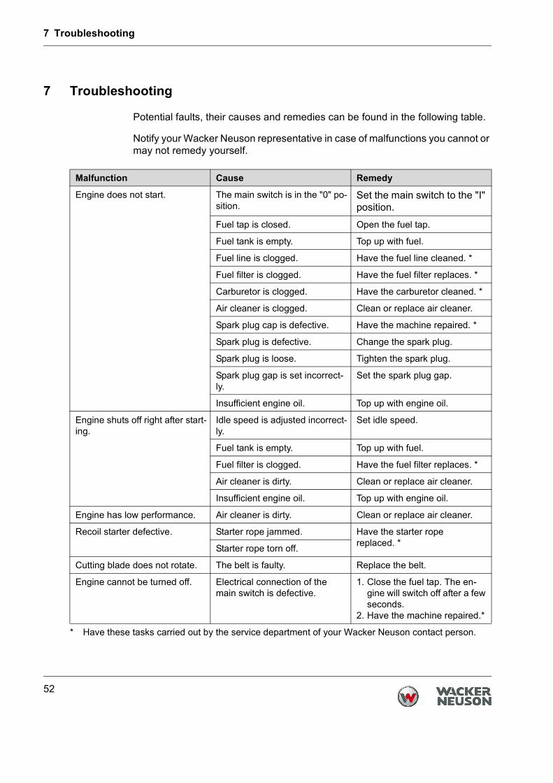
7 Troubleshooting
Potential faults, their causes and remedies can be found in the following table.
Notify your Wacker Neuson representative in case of malfunctions you cannot or may not remedy yourself.
Malfunction Cause Remedy
Engine does not start. The main switch is in the "0" po-sition.
Set the main switch to the "I" position.
Fuel tap is closed. Open the fuel tap.
Fuel tank is empty. Top up with fuel.
Fuel line is clogged. Have the fuel line cleaned. *
* Have these tasks carried out by the service department of your Wacker Neuson contact person.
Fuel filter is clogged. Have the fuel filter replaces. *
Carburetor is clogged. Have the carburetor cleaned. *
Air cleaner is clogged. Clean or replace air cleaner.
Spark plug cap is defective. Have the machine repaired. *
Spark plug is defective. Change the spark plug.
Spark plug is loose. Tighten the spark plug.
Spark plug gap is set incorrect-ly.
Set the spark plug gap.
Insufficient engine oil. Top up with engine oil.
Engine shuts off right after start-ing.
Idle speed is adjusted incorrect-ly.
Set idle speed.
Fuel tank is empty. Top up with fuel.
Fuel filter is clogged. Have the fuel filter replaces. *
Air cleaner is dirty. Clean or replace air cleaner.
Insufficient engine oil. Top up with engine oil.
Engine has low performance. Air cleaner is dirty. Clean or replace air cleaner.
Recoil starter defective. Starter rope jammed. Have the starter rope replaced. *Starter rope torn off.
Cutting blade does not rotate. The belt is faulty. Replace the belt.
Engine cannot be turned off. Electrical connection of the main switch is defective.
1. Close the fuel tap. The en-gine will switch off after a few seconds.
2. Have the machine repaired.*

Translation of the original Declaration of Conformity
EC Declaration of ConformityManufacturer
Wacker Neuson Produktion GmbH & Co. KG, Preußenstraße 41, 80809 MünchenProduct
Conformity assessment procedureAccording to 2000/14/EC, Appendix V.
Guidelines and standardsWe hereby declare that this product meets and complies with the relevant regulations and requirements of the following guidelines and standards:2006/42/EG, 2000/14/EG, 2004/108/EG, EN 55012:2007
Authorized person for technical documentsAxel Häret,Wacker Neuson Produktion GmbH & Co. KG, Preußenstraße 41, 80809 München
Product BFS 935 BFS 1345
Product category Floor saw
Product function Joint cutting
Item number 0610327 0610328 0610141 0610142, 0610243
0610242
Net installed power 6,3 kW 6,6 kW 8,7 kW 9,9 kW 8,7 kW
Measured sound power level
102 dB(A) 102 dB(A) 106 dB(A) 106 dB(A) 105 dB(A)
Guaranteed sound power level
103 dB(A) 103 dB(A) 107 dB(A) 107 dB(A) 107 dB(A)
Dr. Michael FischerDirector of Technology and Innovation
München, 01.08.2011


