bharat heavy electricals limited · bharat heavy electricals limited (a government of india...
TRANSCRIPT

Bharat Heavy Electricals Limited (A Government of India Undertaking) Power Sector – Eastern Region Plot No. 9/1, Block-DJ, Salt Lake City, Kolkata – 700 091 (INDIA) Phone no. 033 - 2321 1691 Fax : 033 - 2321 1960 Web : www.jantermanter.com / www.bhel.com
--------------------------------------------------------------------------------------------------------------- Regd. Office : BHEL House, Siri Fort, New Delhi- 110049
TENDER CHANGE NOTE 01 (TCN – 01) DT:04-05-2007
WITH REFERENCE TO THE NIT, PUBLISHED IN THE WEB SITES FOR PROVIDING FIELD QUALITY ASSURANCE SERVICES FOR CIVIL, STRUCTURAL, TG, BOILER & PIPING, ELECTRICAL AND C&I WORKS AND SAFETY SERVICES FOR 1X250 MW UNIT # 3 AT BUDGE-BUDGE PROJECT, CESC, WEST BENGAL., FOLLOWING CHANGES MAY PLEASE BE NOTED AND COMPLIED WHILE SUBMITTING THE OFFER FOR THE SUBJECT JOB. REF: TENDER DOCUMENT NO - PSER:SCT:BDG-Q742:07 01. Clarification on pre-bid discussion. 02. Sample quality plan BIDDERS TO NOTE THAT TCN-01 WILL FORM PART OF TERMS & CONDITION OF TENDER DOCUMENT. ALL OTHER TERMS & CONDITIONS OF THE TENDER REMAIN UNCHANGED. BIDDERS ARE REQUESTED TO SUBMIT OFFER BY DUE DATE.
SR MANAGER (SCT)

CLARIFICATIONS OF PRE-BID DISCUSSION ON 26/04/2007 AT PSER ,HQ, KOLKATA FOR PROVIDING FIELD QUALITY ASSURANCE SERVICES FOR CIVIL, STRUCTURAL, TG, BOILER & PIPING, ELECTRICAL AND C&I WORKS AND SAFETY SERVICES FOR CESC – BUDGE BUDGE PROJECT (1x 250 MW) – EXTENSION UNIT – 3.
(TENDER NO - PSER:SCT:BDG-Q742:07) Page 1 of 1
Sl no
Description/ tender clause no Tender clause Bidder’s querries Clarifications by BHEL
A. NIT & VOL-I A.1
NIT, Annexure –II Sl. No. 8.0 & 9.3
Proposed deployment plan for subject job
Description remains same. Please clarify.
Sl No. 8 shall be read as:- “Proposed deployment plan of T & Ps for subject job “
Sl No. 9.3 of shall be read as:- “Proposed deployment plan of manpower for subject job”
A.2 VOL-I, Annexure-H, Sl. No. 14
Valid Income Tax clearance certificate
Under GOI Notification , this is not required
AGREED
A.3 Sample Field quality plan
Attached with this TCN
B. VOL-II B.1 CLAUSE 3.0
CATEGORY : “f”
• Qualified Safety Officer -26 Man-months
Does it imply that an extra man is to be deployed for one month only?
shall be read as: • Qualified Safety Officer-25 Man-months
B.2 CLAUSE 19.0 CATEGORY : “f”
In case Contractor deploys the manpower beyond the period specified in the Contract, BHEL will have no obligation to accept the crane and reserves the right ………
The word “crane” may be a typographical error ___
In case Contractor deploys the manpower beyond the period specified in the Contract, BHEL will have no obligation to accept the same and reserves the right ………
B3 CLAUSE 7.0 Gr.-a,b,c,d,e
Max age in any case should not be more than 35 years.
___
Shall be read as: Max age in any case should not be more than 40 years.
B4 Clause No. 5.9, 5.9(a), 5.9(b), 13.4
For witnessing of testing outside the project site, in Kolkata or else where………..
Visit to Kolkata needs review.
Provision for making additional payment towards witnessing the testing in Kolkata is not applicable for this contract and is withdrawn. As such, Clause No. 5.9, 5.9(a), 5.9(b), 13.4 and other sections of the tender should be read accordingly.
C. VOL-III C1 VOL-III, Rate
Schedule, GROUP f: (SAFETY) QTY Column
26
Does it imply that an extra man is to be deployed for one month only?
Shall be read as 25 instead of 26

QUALITY PLAN FOR INSTALLATION
POWER HOUSE STRUCTURAL STEEL WORKS (ERECTION)
MEJIA TPS EXTN. ( UNIT 5 & 6)
2 x 250 MW
BHARAT HEAVY ELECTRICALS LIMITED POWER SECTOR EASTERN REGION
DOC. NO. QPE-CL-04-52 REV. NO. R00
FMT-QP-001 REV.01
QUALITY PLAN FOR
INSTALLATION
POWER HOUSE STRUCTURAL STEEL WORKS (ERECTION)
MEJIA TPS EXTN. (UNITS 5 & 6 ) ( 2 x 250 MW )
PREPARED BY
SR MANAGER/QLY, PSER
APPROVED BY HEAD / QLY, PSER
DOCUMENT NO. QPE - CL – 04-52
ORIGINAL DATE OF ISSUE 20.08.2004 REVISION NO. & DATE R00 / 20.08.2004 COPY NO.
ISSUED TO
DATE OF ISSUE
CONTROLLED / INFORMATION COPY
ISSUED BY (SIGNATURE & DESIGNATION)
BHARAT HEAVY ELECTRICALS LIMITED POWER SECTOR EASTERN REGION
DOC. NO. : QPE-CL-04-52 REV. NO. : R00
PSER
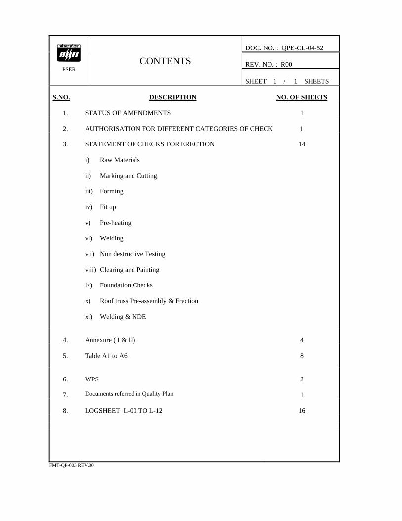
CONTENTS
SHEET 1 / 1 SHEETS S.NO.
DESCRIPTION
NO. OF SHEETS
1.
STATUS OF AMENDMENTS
1
2.
AUTHORISATION FOR DIFFERENT CATEGORIES OF CHECK
1
3.
STATEMENT OF CHECKS FOR ERECTION i) Raw Materials ii) Marking and Cutting iii) Forming iv) Fit up v) Pre-heating vi) Welding vii) Non destructive Testing viii) Clearing and Painting ix) Foundation Checks x) Roof truss Pre-assembly & Erection xi) Welding & NDE
14
4.
Annexure ( I & II)
4
5.
Table A1 to A6
8
6.
WPS
2
7.
Documents referred in Quality Plan
1
8.
LOGSHEET L-00 TO L-12
16
FMT-QP-003 REV.00
DOC. NO. : QPE-CL-04-52 REV. NO. : R00
PSER
STATUS OF AMENDMENTS
SHEET 1 / 1 SHEETS SL. NO.
REFERENCE OF SHEETS AMENDED
AMENDMENT NO. & DATE
REMARKS
-NIL -
FMT-QP-016 REV.00
PSER
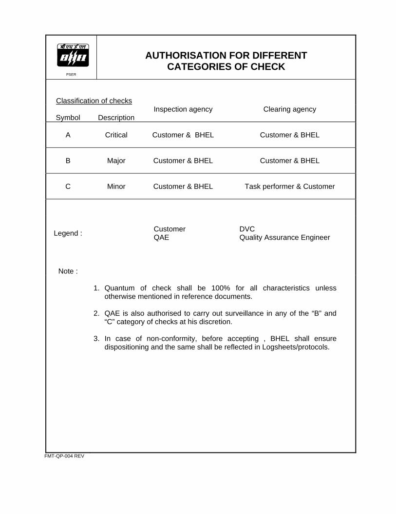
AUTHORISATION FOR DIFFERENT CATEGORIES OF CHECK
Classification of checks
Symbol
Description
Inspection agency Clearing agency
A
Critical
Customer & BHEL
Customer & BHEL
B
Major
Customer & BHEL
Customer & BHEL
C
Minor
Customer & BHEL
Task performer & Customer
Legend :
Customer QAE
DVC Quality Assurance Engineer
Note :
1. Quantum of check shall be 100% for all characteristics unless
otherwise mentioned in reference documents. 2. QAE is also authorised to carry out surveillance in any of the “B” and
“C” category of checks at his discretion. 3. In case of non-conformity, before accepting , BHEL shall ensure
dispositioning and the same shall be reflected in Logsheets/protocols.
FMT-QP-004 REV
PSER
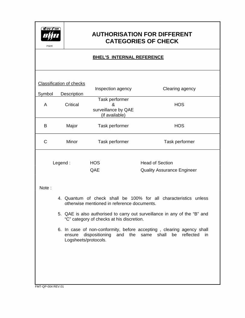
AUTHORISATION FOR DIFFERENT CATEGORIES OF CHECK
BHEL'S INTERNAL REFERENCE
Classification of checks
Symbol
Description
Inspection agency Clearing agency
A
Critical
Task performer &
surveillance by QAE (if available)
HOS
B
Major
Task performer
HOS
C
Minor
Task performer
Task performer
Legend :
HOS
Head of Section
QAE Quality Assurance Engineer
Note :
4. Quantum of check shall be 100% for all characteristics unless
otherwise mentioned in reference documents. 5. QAE is also authorised to carry out surveillance in any of the “B” and
“C” category of checks at his discretion. 6. In case of non-conformity, before accepting , clearing agency shall
ensure dispositioning and the same shall be reflected in Logsheets/protocols.
FMT-QP-004 REV.01

DOC. NO. : QPE-CL-04-52 REV. NO. : R00
PSER
STATEMENT OF CHECKS
SHEET 1 / 14 SHEETS
Capacity / Type :
2 x 250 MW
System :
Power House Structural Steel Works
Sub-system :
------------------------
Area :
Erection
NOTES :
1. For checks where logsheets are not called for, suitable records should be maintained in the form of logsheets / protocols.
2. As an evidence of having carried out the work satisfactorily, a general purpose logsheet, L-00 shall be maintained for all the checks. 3. Drawing / Contract requirements shall apply over and above the checks given.
4. Abbreviations used in the column ‘Type of check’ are:
R : Record verification M: Measurement V : Visual P : Physical
T : Test FMT-QP-005 REV.00
DOC. NO. QPE-CL-04-52
PSER
STATEMENT OF CHECKS REV. NO. R00
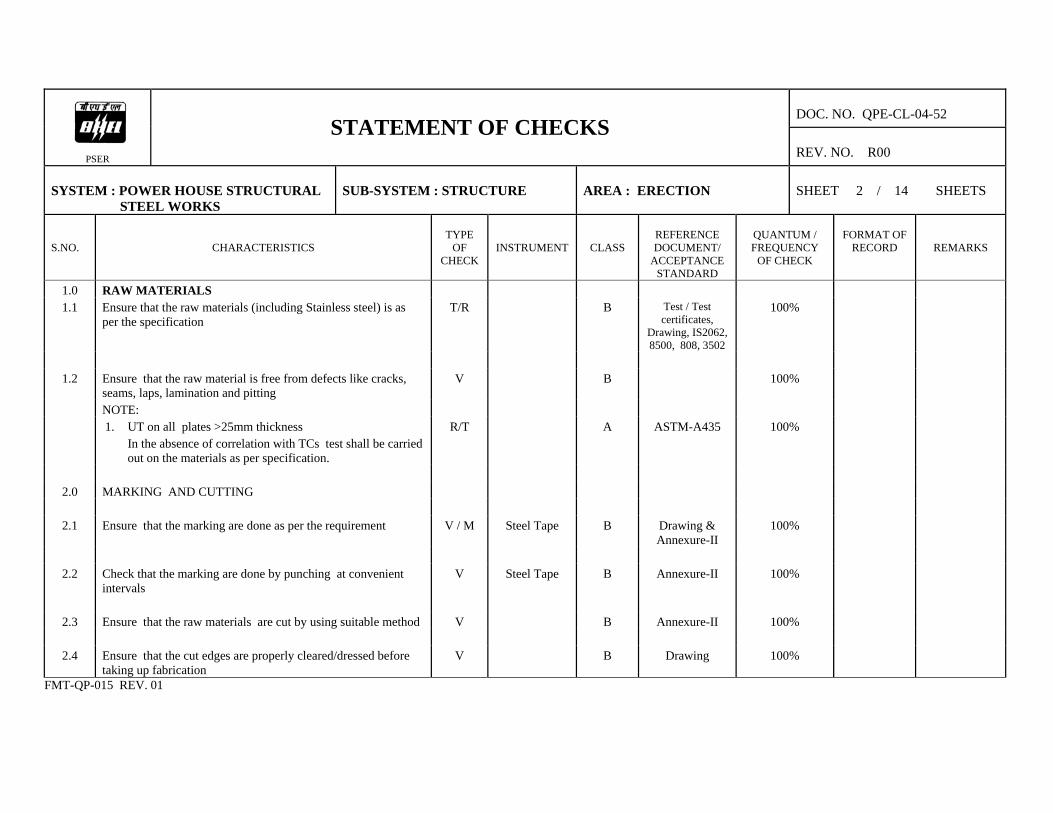
SYSTEM : POWER HOUSE STRUCTURAL STEEL WORKS
SUB-SYSTEM : STRUCTURE
AREA : ERECTION
SHEET 2 / 14 SHEETS
S.NO.
CHARACTERISTICS
TYPE
OF CHECK
INSTRUMENT
CLASS
REFERENCE DOCUMENT/
ACCEPTANCE STANDARD
QUANTUM / FREQUENCY
OF CHECK
FORMAT OF
RECORD
REMARKS
1.0 RAW MATERIALS 1.1 Ensure that the raw materials (including Stainless steel) is as
per the specification T/R B Test / Test
certificates, Drawing, IS2062, 8500, 808, 3502
100%
1.2 Ensure that the raw material is free from defects like cracks,
seams, laps, lamination and pitting V B 100%
NOTE: 1. UT on all plates >25mm thickness
In the absence of correlation with TCs test shall be carried out on the materials as per specification.
R/T A ASTM-A435 100%
2.0 MARKING AND CUTTING
2.1 Ensure that the marking are done as per the requirement V / M Steel Tape B Drawing &
Annexure-II 100%
2.2 Check that the marking are done by punching at convenient
intervals V Steel Tape B Annexure-II 100%
2.3 Ensure that the raw materials are cut by using suitable method V B Annexure-II 100%
2.4 Ensure that the cut edges are properly cleared/dressed before
taking up fabrication V B Drawing 100%
FMT-QP-015 REV. 01

DOC. NO. QPE-CL-04-52
PSER
STATEMENT OF CHECKS REV. NO. R00
SYSTEM : POWER HOUSE STRUCTURAL STEEL WORKS
SUB-SYSTEM : STRUCTURE
AREA : ERECTION
SHEET 3 / 14 SHEETS
S.NO.
CHARACTERISTICS
TYPE
OF CHECK
INSTRUMENT
CLASS
REFERENCE DOCUMENT/
ACCEPTANCE STANDARD
QUANTUM / FREQUENCY
OF CHECK
FORMAT OF
RECORD
REMARKS
2.5 Check that the raw materials after cutting are identified with
part number. V B Drawing 100%
3.0 FORMING (If applicable)
3.1 Ensure that forming is done using proper tooling free from
damages. V C Drawing 100%
4.0 FIT UP:
4.1 Ensure proper fit up before welding M Measuring Tape B Drawing 100% Protocol
4.2 Check that the gap is minimum for all fillet welds ( max. gap
2 mm ) M Measuring Tape B Drawing 100% Protocol
4.3 Ensure that the butt weld joints are properly aligned and the
offset is not to exceed 10% of the thickness of the thinner part of the joint. Maximum permitted value is 3.2 mm.
M Measuring Tape B Drawing 100% Protocol
4.4 Ensure match markings are punched for all trial assembled
components. M Measuring Tape B Drawing 100% Protocol
FMT-QP-015 REV. 01

DOC. NO. QPE-CL-04-52
PSER
STATEMENT OF CHECKS REV. NO. R00
SYSTEM : POWER HOUSE STRUCTURAL STEEL WORKS
SUB-SYSTEM : STRUCTURE
AREA : ERECTION
SHEET 4 / 14 SHEETS
S.NO.
CHARACTERISTICS
TYPE
OF CHECK
INSTRUMENT
CLASS
REFERENCE DOCUMENT/
ACCEPTANCE STANDARD
QUANTUM / FREQUENCY
OF CHECK
FORMAT OF
RECORD
REMARKS
5.0 PREHEATING:
5.1 Ensure pre heating is carried out wherever applicable. (using appropriate method)
V Thermal chalk B Annexure-II 100% Protocol
5.2 Ensure that the preheating temperature is uniform prior to
start of welding as well as during the welding. V Thermal chalk B Annexure-II 100% Site Log
6.0 WELDING:
6.1 Ensure that the qualified welders and qualified welding
procedures are used for all welding. T/R A Welding
Manual, WPS, IS817 & ASME
SEC. IX
100% Site Log
6.2 Ensure that the welding consumables are as per WPS. R A Welding
Manual, WPS, IS817 & ASME
SEC. IX
100% Site Log
6.3 Ensure proper edge preparation wherever required. V Bevel protractor B Drawing 100% Site Log
6.4 Ensure proper sequence of welding. V B WPS 100%
6.5 Check that the temporary attachment welded are removed
and ground & painted V B 100%
FMT-QP-015 REV. 01

DOC. NO. QPE-CL-04-52
PSER
STATEMENT OF CHECKS REV. NO. R00
SYSTEM : POWER HOUSE STRUCTURAL STEEL WORKS
SUB-SYSTEM : STRUCTURE
AREA : ERECTION
SHEET 5 / 14 SHEETS
S.NO.
CHARACTERISTICS
TYPE
OF CHECK
INSTRUMENT
CLASS
REFERENCE DOCUMENT/
ACCEPTANCE STANDARD
QUANTUM / FREQUENCY
OF CHECK
FORMAT OF
RECORD
REMARKS
6.6 Check and ensure that the overlap/excess weld metal is removed by grinding and painted.
V B 100%
6.7 Check the measurement of parts after welding for the
correctness of dimension & matching. M Measuring Tape B Drawing 100% Protocol
7.0 NON DESTRUCTIVE TESTING:
7.1 Carry out RT/UT/LPI as applicable T Testing
equipment A Drawing ,
Annexure-I & NDE Manual
As per Annexure-I
protocol
8.0 CLEANING AND PAINTING:
8.1 Ensure that the surface are cleaned and painted as specified V B Specification 100%
8.2 Ensure that the following markings are done
a)Assemblies designation V C Drawing 100% b)Part Number V C Drawing 100% c)Any other important identifications V C Drawing 100%
8.3 Ensure Dry Film Thickness of paint is as per specification M B Specification 100% Note : All tolerances during fabrication should be as per
Annexure-II
FMT-QP-015 REV. 01
DOC. NO. QPE-CL-04-52
PSER
STATEMENT OF CHECKS REV. NO. R00
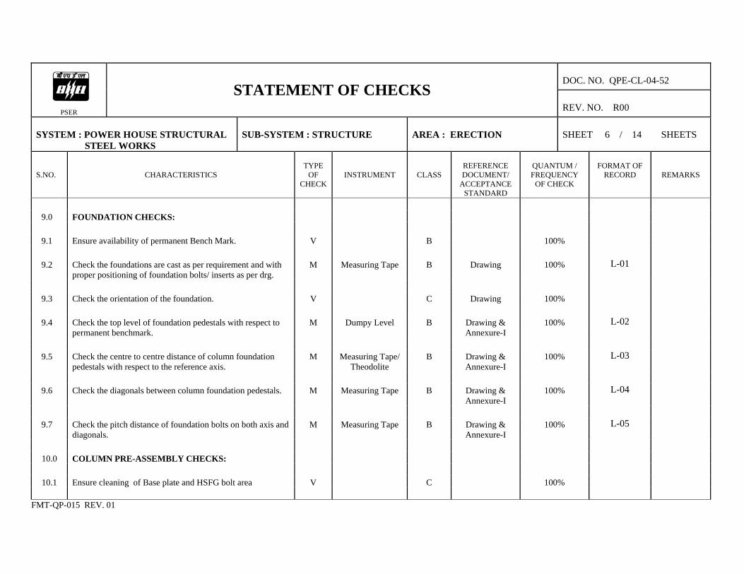
SYSTEM : POWER HOUSE STRUCTURAL STEEL WORKS
SUB-SYSTEM : STRUCTURE
AREA : ERECTION
SHEET 6 / 14 SHEETS
S.NO.
CHARACTERISTICS
TYPE
OF CHECK
INSTRUMENT
CLASS
REFERENCE DOCUMENT/
ACCEPTANCE STANDARD
QUANTUM / FREQUENCY
OF CHECK
FORMAT OF
RECORD
REMARKS
9.0 FOUNDATION CHECKS:
9.1 Ensure availability of permanent Bench Mark. V B 100%
9.2 Check the foundations are cast as per requirement and with
proper positioning of foundation bolts/ inserts as per drg. M Measuring Tape B Drawing 100% L-01
9.3 Check the orientation of the foundation. V C Drawing 100%
9.4 Check the top level of foundation pedestals with respect to
permanent benchmark. M Dumpy Level B Drawing &
Annexure-I 100% L-02
9.5 Check the centre to centre distance of column foundation
pedestals with respect to the reference axis. M Measuring Tape/
Theodolite B Drawing &
Annexure-I 100% L-03
9.6 Check the diagonals between column foundation pedestals. M Measuring Tape B Drawing &
Annexure-I 100% L-04
9.7 Check the pitch distance of foundation bolts on both axis and
diagonals. M Measuring Tape B Drawing &
Annexure-I 100% L-05
10.0 COLUMN PRE-ASSEMBLY CHECKS:
10.1 Ensure cleaning of Base plate and HSFG bolt area V C 100%
FMT-QP-015 REV. 01
DOC. NO. QPE-CL-04-52
PSER
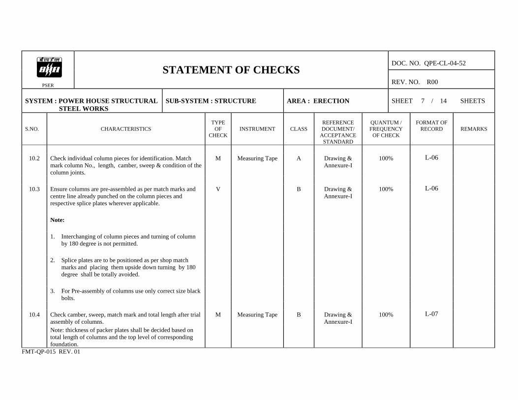
STATEMENT OF CHECKS REV. NO. R00
SYSTEM : POWER HOUSE STRUCTURAL STEEL WORKS
SUB-SYSTEM : STRUCTURE
AREA : ERECTION
SHEET 7 / 14 SHEETS
S.NO.
CHARACTERISTICS
TYPE
OF CHECK
INSTRUMENT
CLASS
REFERENCE DOCUMENT/
ACCEPTANCE STANDARD
QUANTUM / FREQUENCY
OF CHECK
FORMAT OF
RECORD
REMARKS
10.2 Check individual column pieces for identification. Match
mark column No., length, camber, sweep & condition of the column joints.
M Measuring Tape A Drawing & Annexure-I
100% L-06
10.3 Ensure columns are pre-assembled as per match marks and
centre line already punched on the column pieces and respective splice plates wherever applicable.
V B Drawing & Annexure-I
100% L-06
Note: 1. Interchanging of column pieces and turning of column
by 180 degree is not permitted.
2. Splice plates are to be positioned as per shop match
marks and placing them upside down turning by 180 degree shall be totally avoided.
3. For Pre-assembly of columns use only correct size black
bolts.
10.4 Check camber, sweep, match mark and total length after trial
assembly of columns. M Measuring Tape B Drawing &
Annexure-I 100% L-07
Note: thickness of packer plates shall be decided based on total length of columns and the top level of corresponding foundation.
FMT-QP-015 REV. 01

DOC. NO. QPE-CL-04-52
PSER
STATEMENT OF CHECKS REV. NO. R00
SYSTEM : POWER HOUSE STRUCTURAL STEEL WORKS
SUB-SYSTEM : STRUCTURE
AREA : ERECTION
SHEET 8 / 14 SHEETS
S.NO.
CHARACTERISTICS
TYPE
OF CHECK
INSTRUMENT
CLASS
REFERENCE DOCUMENT/
ACCEPTANCE STANDARD
QUANTUM / FREQUENCY
OF CHECK
FORMAT OF
RECORD
REMARKS
11.0 ROOF TRUSS PREASSEMBLY CHECKS BETWEEN ROWS
11.1 Ensure roof trusses are pre-assembled as per match mark and
C.G line punched on top and bottom angles. V B Drawing &
Annexure-I 100%
11.2 Check the following
a) Camber M Measuring Tape B Drawing & Annexure-I
100% L-08
b) Sweep M Measuring Tape B Drawing &
Annexure-I 100% L-08
c) Alignment of CG line punch mark and the match mark
given on the top & bottom angles, permitted devitation in C.G line matching is ±5 mm)
M Measuring Tape B Drawing & Annexure-I
100%
d) Horizontal level of assembled roof truss with water
level with respect to centre line punch mark on end gusset plate face permitted deviation is ± 5mm
M Measuring Tape B Drawing & Annexure-I
100%
e) Total length of assembled roof truss between faces of
end gusset plates at top & bottom (Permitted deviation is ± 5 mm.
M Measuring Tape B Drawing & Annexure-I
100%
f) End plates are aligned and in one plane on both the ends. M Measuring Tape B Drawing &
Annexure-I 100%
FMT-QP-015 REV. 01

DOC. NO. QPE-CL-04-52
PSER
STATEMENT OF CHECKS REV. NO. R00
SYSTEM : POWER HOUSE STRUCTURAL STEEL WORKS
SUB-SYSTEM : STRUCTURE
AREA : ERECTION
SHEET 9 / 14 SHEETS
S.NO.
CHARACTERISTICS
TYPE
OF CHECK
INSTRUMENT
CLASS
REFERENCE DOCUMENT/
ACCEPTANCE STANDARD
QUANTUM / FREQUENCY
OF CHECK
FORMAT OF
RECORD
REMARKS
11.3 Ensure the following during welding of roof truss.
a) Proper fit up M / V Measuring Tape B Drawing 100% b) Qualified welders are engaged and qualified
procedures are employed T / R B Drawing,
Welding Manual & Annexure-I
100%
c) Recommended welding consumables and methods are
employed. T / R A Drawing &
Annexure-I 100%
d) LPI on finished welds 100% for butt welds and 10% for
fillet welds. T / R B Drawing &
Annexure-I 100%
Butt Welds : 1. Radiography : Spot radiography shall be carried out on 100 % joints in Tension zone and 10% joints in Compression zone. Minimum 300 mm length shall be spot radiographed. When radiography is not possible, Ultrasonic test shall be carried out after grinding the surface 2. Ultrasonic Test : 10 % of all other Butt welds shall be subject to spot radiography test and the entire balance butt weld for Ultrasonic test
Class of check `A' Acceptance standard as
per NDE Manual.
FMT-QP-015 REV. 01
DOC. NO. QPE-CL-04-52
PSER
STATEMENT OF CHECKS REV. NO. R00
SYSTEM : POWER HOUSE STRUCTURAL STEEL WORKS
SUB-SYSTEM : STRUCTURE
AREA : ERECTION
SHEET 10 / 14 SHEETS
S.NO.
CHARACTERISTICS
TYPE
OF CHECK
INSTRUMENT
CLASS
REFERENCE DOCUMENT/
ACCEPTANCE STANDARD
QUANTUM / FREQUENCY
OF CHECK
FORMAT OF
RECORD
REMARKS
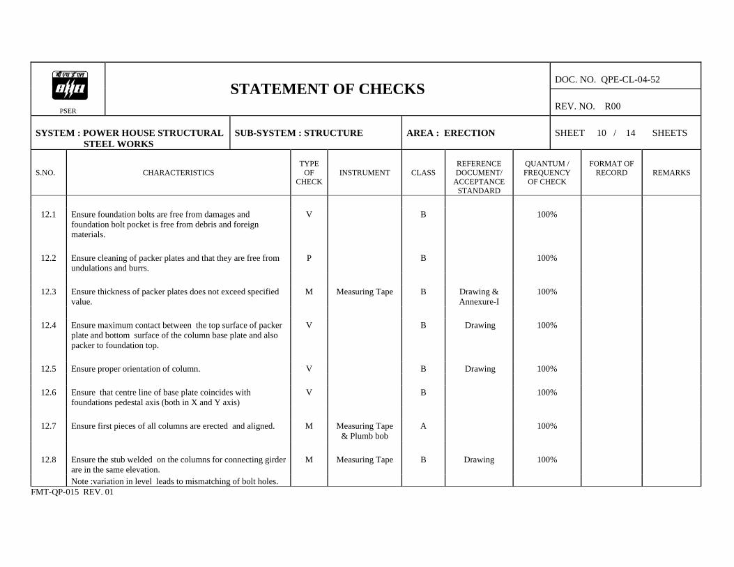
12.1 Ensure foundation bolts are free from damages and
foundation bolt pocket is free from debris and foreign materials.
V B 100%
12.2 Ensure cleaning of packer plates and that they are free from
undulations and burrs. P B 100%
12.3 Ensure thickness of packer plates does not exceed specified
value. M Measuring Tape B Drawing &
Annexure-I 100%
12.4 Ensure maximum contact between the top surface of packer
plate and bottom surface of the column base plate and also packer to foundation top.
V B Drawing 100%
12.5 Ensure proper orientation of column. V B Drawing 100%
12.6 Ensure that centre line of base plate coincides with
foundations pedestal axis (both in X and Y axis) V B 100%
12.7 Ensure first pieces of all columns are erected and aligned. M Measuring Tape
& Plumb bob A 100%
12.8 Ensure the stub welded on the columns for connecting girder
are in the same elevation. M Measuring Tape B Drawing 100%
Note :variation in level leads to mismatching of bolt holes. FMT-QP-015 REV. 01
DOC. NO. QPE-CL-04-52
PSER
STATEMENT OF CHECKS REV. NO. R00
SYSTEM : POWER HOUSE STRUCTURAL STEEL WORKS
SUB-SYSTEM : STRUCTURE
AREA : ERECTION
SHEET 11 / 14 SHEETS
S.NO.
CHARACTERISTICS
TYPE
OF CHECK
INSTRUMENT
CLASS
REFERENCE DOCUMENT/
ACCEPTANCE STANDARD
QUANTUM / FREQUENCY
OF CHECK
FORMAT OF
RECORD
REMARKS
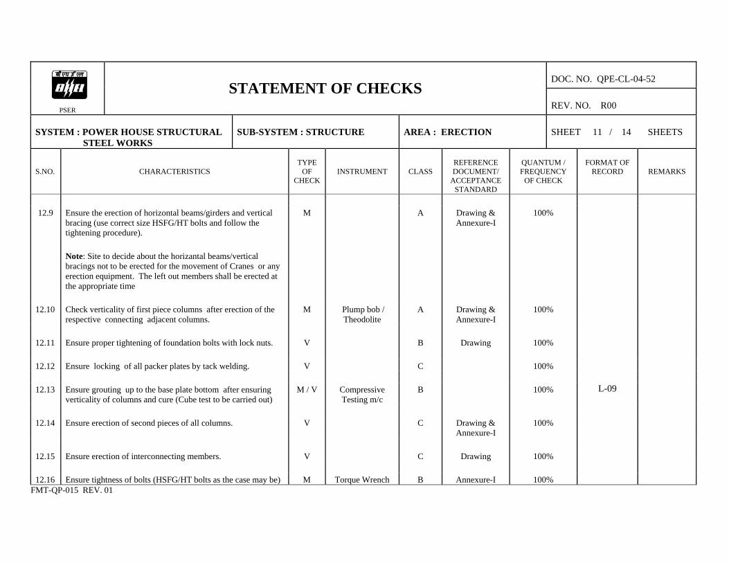
12.9 Ensure the erection of horizontal beams/girders and vertical
bracing (use correct size HSFG/HT bolts and follow the tightening procedure).
M A Drawing & Annexure-I
100%
Note: Site to decide about the horizantal beams/vertical bracings not to be erected for the movement of Cranes or any erection equipment. The left out members shall be erected at the appropriate time
12.10 Check verticality of first piece columns after erection of the
respective connecting adjacent columns. M Plump bob /
Theodolite A Drawing &
Annexure-I 100%
12.11 Ensure proper tightening of foundation bolts with lock nuts. V B Drawing 100% 12.12 Ensure locking of all packer plates by tack welding. V C 100% 12.13 Ensure grouting up to the base plate bottom after ensuring
verticality of columns and cure (Cube test to be carried out) M / V Compressive
Testing m/c B 100% L-09
12.14 Ensure erection of second pieces of all columns. V C Drawing &
Annexure-I 100%
12.15 Ensure erection of interconnecting members. V C Drawing 100% 12.16 Ensure tightness of bolts (HSFG/HT bolts as the case may be) M Torque Wrench B Annexure-I 100%
FMT-QP-015 REV. 01
DOC. NO. QPE-CL-04-52
PSER
STATEMENT OF CHECKS REV. NO. R00
SYSTEM : POWER HOUSE STRUCTURAL STEEL WORKS
SUB-SYSTEM : STRUCTURE
AREA : ERECTION
SHEET 12 / 14 SHEETS
S.NO.
CHARACTERISTICS
TYPE
OF CHECK
INSTRUMENT
CLASS
REFERENCE DOCUMENT/
ACCEPTANCE STANDARD
QUANTUM / FREQUENCY
OF CHECK
FORMAT OF
RECORD
REMARKS
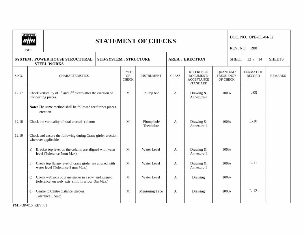
12.17 Check verticality of 1st and 2nd pieces after the erection of
Connecting pieces. M Plump bob A Drawing &
Annexure-I 100% L-09
Note: The same method shall be followed for further pieces
erection
12.18 Check the verticality of total erected column M Plump bob/
Theodolite A Drawing &
Annexure-I 100% L-10
12.19 Check and ensure the following during Crane girder erection
wherever applicable
a) Bracket top level on the column are aligned with water
level (Tolerance 5mm Max) M Water Level A Drawing &
Annexure-I 100%
b) Check top flange level of crane girder are aligned with
water level (Tolerance 5 mm Max.) M Water Level A Drawing &
Annexure-I 100% L-11
c) Check web axis of crane girder in a row and aligned
(tolerance on web axis shift in a row 3m Max.) M Water Level A Drawing 100%
d) Centre to Centre distance girders M Measuring Tape A Drawing 100% L-12 Tolerance ± 5mm
FMT-QP-015 REV. 01

DOC. NO. QPE-CL-04-52
PSER
STATEMENT OF CHECKS REV. NO. R00
SYSTEM : POWER HOUSE STRUCTURAL STEEL WORKS
SUB-SYSTEM : STRUCTURE
AREA : ERECTION
SHEET 13 / 14 SHEETS
S.NO.
CHARACTERISTICS
TYPE
OF CHECK
INSTRUMENT
CLASS
REFERENCE DOCUMENT/
ACCEPTANCE STANDARD
QUANTUM / FREQUENCY
OF CHECK
FORMAT OF
RECORD
REMARKS
12.20 Ensure the following during the erection of roof trusses
a) Proper handling to avoid damage & distortion to
assembled trusses. V C 100%
b) Alignment of bolt holes between columns and truss
gussets. V C Drawing 100%
c) Slope of truss as per drawing. M Spirit Level /
Water Level B Drawing 100%
d) tightness of bolts. M Torque Wrench B Annexure-I 100% e) truss to truss connecting members including purlins V C Drawing 100%
12.21 HSFG bolts tightening a) Ensure HSFG bolts are tightened by calibrated torque
wrenches. M B 100%
b) Check the tightness of HSFG bolts using calibrated
torque wrench. M Torque Wrench B Drawing 100%
FMT-QP-015 REV. 01
DOC. NO. QPE-CL-040
PSER
STATEMENT OF CHECKS REV. NO. R02
SYSTEM : POWER HOUSE STRUCTURAL STEEL WORKS
SUB-SYSTEM : STRUCTURE
AREA : ERECTION
SHEET 14 / 14 SHEETS
S.NO.
CHARACTERISTICS
TYPE
OF CHECK
INSTRUMENT
CLASS
REFERENCE DOCUMENT/
ACCEPTANCE STANDARD
QUANTUM / FREQUENCY
OF CHECK
FORMAT
OF RECORD
REMARKS
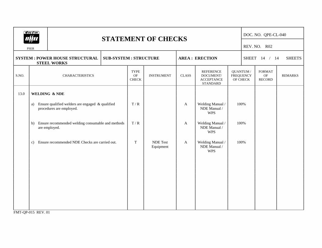
13.0 WELDING & NDE
a) Ensure qualified welders are engaged & qualified
procedures are employed. T / R A Welding Manual /
NDE Manual / WPS
100%
b) Ensure recommended welding consumable and methods
are employed. T / R A Welding Manual /
NDE Manual / WPS
100%
c) Ensure recommended NDE Checks are carried out. T NDE Test
Equipment A Welding Manual /
NDE Manual / WPS
100%
FMT-QP-015 REV. 01

DOC. NO. : QPX-CL-04-52 REV. NO. : R00
PSER
DOCUMENTS REFERRED IN QUALITY PLAN
SHEET 1 / 1 SHEETS
Sl. No.
Reference Document
Issuing Authority
1
2
3
4
5
6.
7.
8.
Drawings WPS Welding Manual NDE Manual IS 817, IS 7215, IS 12843, IS 1852, IS 2062 ASME : Sec IX ASTM A 435 Other codes relevant to raw material, consumables and works
PEM, New Delhi Trichy PS-NR PS-NR Bureau of India Standards (BIS)
FMT-QP-017 REV.00
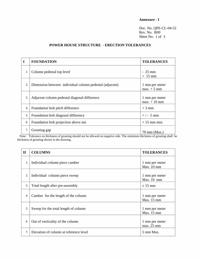
Annexure - I Doc. No. QPE-CL-04-52 Rev. No. R00 Sheet No. 1 of 3
POWER HOUSE STRUCTURE - ERECTION TOLERANCES
I FOUNDATION TOLERANCES
1. Column pedestal top level - 25 mm + 15 mm
2. Dimension between individual column pedestal (adjacent) 1 mm per meter max. + 5 mm
3. Adjacent column pedestal diagonal difference 1 mm per meter max. + 10 mm
4. Foundation bolt pitch difference + 3 mm
5. Foundation bolt diagonal difference + / - 5 mm
6. Foundation bolt projection above nut + 15 mm min.
7. Grouting gap 70 mm (Max.)
Note: Tolerance on thickness of grouting should not be allowed on negative side. The minimum thickness of grouting shall be thickness of grouting shown in the drawing.
II COLUMNS TOLERANCES
1. Individual column piece camber 1 mm per meter Max. 10 mm
2. Individual column piece sweep 1 mm per meter Max. 10 mm
3. Total length after pre-assembly ± 15 mm
4. Camber for the length of the column 1 mm per meter Max. 15 mm
5. Sweep for the total length of column 1 mm per meter Max. 15 mm
6. Out of verticality of the column 1 mm per meter max. 25 mm
7. Elevation of column at reference level 5 mm Max.
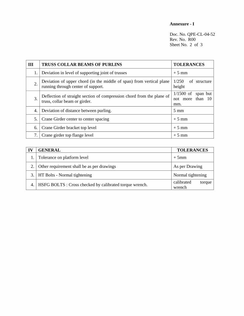
Annexure - I Doc. No. QPE-CL-04-52 Rev. No. R00 Sheet No. 2 of 3
III TRUSS COLLAR BEAMS OF PURLINS TOLERANCES
1. Deviation in level of supporting joint of trusses + 5 mm
2. Deviation of upper chord (in the middle of span) from vertical plane running through center of support.
1/250 of structure height
3. Deflection of straight section of compression chord from the plane of truss, collar beam or girder.
1/1500 of span but not more than 10 mm.
4. Deviation of distance between purling. 5 mm
5. Crane Girder center to center spacing + 5 mm
6. Crane Girder bracket top level + 5 mm
7. Crane girder top flange level + 5 mm
IV GENERAL TOLERANCES 1. Tolerance on platform level + 5mm
2. Other requirement shall be as per drawings As per Drawing
3. HT Bolts - Normal tightening Normal tightening
4. HSFG BOLTS : Cross checked by calibrated torque wrench. calibrated torque wrench

Annexure - I Doc. No. QPE-CL-04-52 Rev. No. R00 Sheet No. 3 of 3
V POWER HOUSE STURCTURE - NDE REQUIREMENTS FOR COLUMNS, CRANE GIRDER FRAME BEAMS TRUSS ETC. COVERING ALL THE STRUCTURES UNDER THE CONTRACT
1.0 FLAME CUT EDGES
Flame out edges for thickness over 50mm - 100% LPI to be done. However for thickness 63 mm and above only 100% MPI shall be done on the flame cut edges.
2.0 BUTT WELDS 2.1 100 % LPI for root run after back gouging
2.2 100% Radiographic testing (RT) on tension zone welds and 10% RT on compression zone welds of crane & bunker girder shall be carried out. Where RT is not possible. Ultrasonic test shall be carried out after grinding the surface.
2.3 10% Radiographic Test (Minimum) & Ultrasonic test for the entire balance butt weld shall be carried out for all structures except structures covered under Sl. No. 2.2
3.0 FILLET WELDS
3.1 Each weld shall be checked for size and visual defects.
3.2 10% weld length on tension members shall be subjected to LPI examination.
3.3 Where the thickness of both the members is greater than 25 mm, LPI shall be done on entire weld length.
3.4 On all other fillet welds, LPI shall be done on minimum 5% of total weld length at random with minimum 300 mm at a particular location.
4.0 COLUMNS:BASE/TOP
100 % LPI
5.0 COAL BUNKERS 100 % NDT of all butt welds and all critical fillet welds are to be
done. Apart from manufacturer’s TC of structural materials, site may organise sample test of steel material at established laboratory during various stages of project activities as per decision of BHEL engineers. Adequate number of safe platforms and easy approach both from bunker floor as well as from feeder floor are to be provided for inspection of fit-up and welding of joints.

Annexure - II
Doc. No. QPE-CL-04-52 Rev. No. R00 Sheet No. 1 of 1
1.0 REQUIREMENT OF PREHEATING
Thickness of thickest part at the point of welding
Other than low hydrogen welding electrodes
Low hydrogen electrodes / submerged arc welding
Upto 20 mm (including) None None
Over 20 mm to 40 mm (including) 65° C 20° C
Over 40 mm to 63 mm (including) 110° C 66° C
Over 63 mm 150° C 110° C
2.0
CUTTING TOLERANCES AND DIMENSIONAL VARIATIONS DURING FABRICATION
AS PER TABLE A1
3.0
TOLARABLE DEVIATIONS OF FARICATED MEMBERS FROM GEOMENTRICAL SHAPE
AS PER TABLE A2
4.0
DEVIATIONS
4.1
ACCEPTABLE DEVIATIONS IN AS FARICATED STEEL STRUCTURES
AS PER TABLE A3
4.2
SPECIFICATION FOR PERMISSIBLE DEVIATION IN BOLT HOLES.
AS PER TABLE A4
4.3
SPECIFICATION FOR PERMISSIBLE DEVIATION OF STRUCTURAL STEEL.
AS PER TABLE A5
4.4
MAXIMUM PERMISSIBLE TOLERANCES IN ERECTED STEEL STRUCTURES.
AS PER TABLE A6
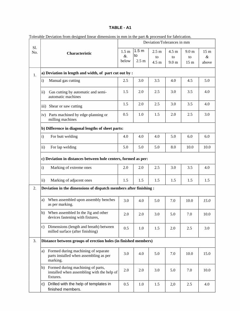
TABLE - A1
Tolerable Deviation from designed linear dimensions in mm in the part & processed for fabrication.
Deviation/Tolerances in mm Sl. No. Characteristic 1.5 m
&. below
1.5 m to
2.5 m
2.5 m to
4.5 m
4.5 m to
9.0 m
9.0 m to
15 m
15 m &
above
a) Deviation in length and width, of part cut out by :
i) Manual gas cutting 2.5 3.0 3.5 4.0 4.5 5.0
ii) Gas cutting by automatic and semi-automatic machines
1.5
2.0
2.5
3.0
3.5
4.0
iii) Shear or saw cutting 1.5 2.0 2.5 3.0 3.5 4.0
iv) Parts machined by edge-planning or milling machines
0.5
1.0
1.5
2.0
2.5
3.0
b) Difference in diagonal lengths of sheet parts:
i) For butt welding
4.0 4.0 4.0 5.0
6.0
6.0
ii) For lap welding 5.0 5.0 5.0 8.0 10.0 10.0
c) Deviation in distances between hole centers, formed as per:
i) Marking of extreme ones
2.0 2.0 2.5 3.0
3.5
4.0
1.
ii) Marking of adjacent ones 1.5 1.5 1.5 1.5 1.5 1.5
Deviation in the dimensions of dispatch members after finishing :
a) When assembled upon assembly benches as per marking.
3.0
4.0
5.0
7.0
10.0
15.0
b) When assembled In the Jig and other devices fastening with fixtures,
2.0
2.0
3.0
5.0
7.0
10.0
2.
c) Dimensions (length and breath) between milled surface (after finishing)
0.5
1.0
1.5
2.0
2.5
3.0
Distance between groups of erection holes (in finished members)
a) Formed during machining of separate parts installed when assembling as per marking.
3.0
4.0
5.0
7.0
10.0
15.0
b) Formed during machining of parts, installed when assembling with the help of fixtures.
2.0
2.0
3.0
5.0
7.0
10.0
3.
c) Drilled with the help of templates in finished members.
0.5
1.0
1.5
2,0
2.5
4.0

TABLE A.2
Tolerable deviations of fabricated member from designed geometrical shape
DeviationS. No. Characteristic Remarks Curvature of assembly Parts
a) Gap between a sheet and a steel rule face over 1 m length
1.5 mm
1.
b) Gap between a taut string and vertex face of an angle flange or web of channel and joist.
0.001 L, but not greater than 10 mm L - length of member
Deviation of edge line steel sheet parts from theoretical profile:
a) During butt and toe welding. 2 mm
2.
b) During lap welding 5 mm
Deviation of radius of the bend:
a) Clearance between template and the surface of rolled sheet flange or face of cold bend profile.
2 mm
Template length (1.5 m along the curve)
b) Clearance between template and the surface of rolled sheet flange or face of hot bend profile
3 mm -do-
c) Ellipticity (difference of diameters) in space sheet structures.
0.005D
D-diameter of circumference
3.
d) Ellipticity (difference of diameters) in erection joints 0.003D -do-
Deformation of dispatch members: a) Inclination of flanges with the web:
i) at Junction point 0.005b b-width of flange
ii) at other places O.Olb b-width of flange
b) Transverse bending of flanges:
i) at junction with members 0.005b b- width of flange
ii) at other places O.Olb b-width of flange
c) Warping of the web
0.003h
h-depth of the member
4.
d) Sag of member
L/750 but not more than 15mm
L-length of the member
5. Other Deviations:
a) Shifting of axes or riveting / bolting lines for lattice structures from theoretical eccentricity.
3.0 mm
b) Inclination of the milled surface from designed position.
1/1500

TABLE-A.3
Acceptance Deviations in as fabricates steel structures. Sl. No.
Characteristic Deviation / Tolerance
COLUMNS
Deviation in length 'L' measured distance from bottom surface of the column footings, to the group of holes for trusses, fasteners, collar beams, purlins and other elements to be connected to column. When L is under 10 m ± 10 mm
a) When L is over 10 m ± l5 mm
Deviation in distance 'L' from bottom surface of the column footing to the top of crane brackets.
When L is under 10 m ± 5 mm
b) when L is over 10 m ± 10 mm
c)
Deviation in distance from bearing surface of the bracket to the first fastener of the element to the connected to column.
± 1 mm
d)
Deviation in distance between any group of holes for connection of bracings to column.
± 2 mm
e)
Sag of column element (curvature)
1/1000 of length element but not more
f) Difference in web depth of column
i) At splice joint ± 2 mm
ii) At any other location ± 10 mm
1.
g)
Deviation in distance from supporting surface of milled end of the despatch element of column to the clear or heating plate or column to the cleat or seating plate for fastening of collar beams, purlins, girders. etc. (Fish plates, brackets)
± 3 mm
TRUSSES
a) Deviation in span 'L' of the truss between end erection holes in gussets of supporting units or between external planes of supporting gussets or angles when trusses are resting on brackets or supports:
When L is under 25 m ± 7 mm
When L is over 25 m
1/2500 but not more than 10 mm
b) b) Deviation in distance between the centres of holes or webs of angles for fastening bracing, purlins, monitors etc
± 3 mm
c) Deviation in distance between the first row of erection holes and the bearing surface at cleat or seating plate.
± 1 mm
d) Distance between holes for fasteners to top and bottom chords of trusses on
supports. ± 3 mm
2.
e) Sag of separate elements between node points.
1/1500 of length of element but not more than 10 mm.

TABLE A.3
S. No
Characteristic Deviation/ Tolerance
3. BEAMS
a) Deviation in span L of beams between bend erection holes, outer Surfaces of end plates:
When L is under 25 m ± 10 mm
When T is over 25 m
± 1/2500 Length but not more than 15 mm
b) Deviation in the height of beam as measured from the bearing surface to the top of upper flange.
± 3 mm
c) Deviation in distance between the group of holes for fastening of purlins, monitors, bracings, bracing grids etc.
± 3 mm
d) Sag (curvature) of the girder despatch member
1/1000 length but not more than 15 mm
4. ELEMENTS OF FRAMEWORK BRACINGS, PURLINS ETC.
a) Deviation in distance between end erection holes, determining the span of element.
± 13 mm
b) Sag of despatch members
1/1000 length but not more than 15 mm
c) Deviation in distance between the groups of erection holes of the element. ± 3 mm
d) Gratings, Stair / Railings, ladders etc. ± 12 mm
5. SHOP ASSEMBLY (Before DESPATCH FOR ERECTION)
a) Columns weighing more than 20 T
b) Roof trusses of 30 m or more span
Every first and further every fourth set of identical structure to be put for control assembly,
c) Crane girders with span more than 18 m
d) Bunkers
Number of erection bolts shall be at least 30% of the total No. of holes.

TABLE-A.4
Acceptable Deviation in Holes for Bolts S.No, Characteristic Deviation
Tolerance No. of
deviation in each group
a) Deviation of dia of holes for rivet and bolts
Upto 16 mm + 1 mm No limit
1,
Over 16 mm + 1.5 mm
b) Deviations of dia of turned and fitted bolts: Nominal dia of bolts and holes
Upper limit: +0.125 mm Lower limit: 0.00
No limit
Ovalness (difference between the greatest and lesser dia)
Upto 16 mm hole dia + 1 mm No limit
2.
Over 16 mm hole dia + 1.5 mm
3.
Deformity in size greater than 1.5 mm and cracks in the edge of holes.
Not permitted
Misalignment of holes in separate plates in the joints:
i) Upto 1 mm Upto 50%
4.
ii) From 1 to 1.5 mm
Upto 10%
NOTE : Burrs in holes shall be removed, the depth and width of countersunk hole shall not deviate from the standard by more than 1.5 mm.

Table A 5
Permissible Fabrication Deviation of Structural Steel
S No. Type of Structures and Constructions Name of Deviations Value of Deviation
(Tolerance)
1. Column Assembly Fits a) Base plate and column 0.1 mm b) Frame Joints 2.0 mm
c) Web and flange 1.5 mm
d) Web & stiffeners 1.5 mm
e) Flange & stiffeners Intermediate stiffeners & Bearing stiffeners:
1.5 mm
f) Cap plate & column 0.1 mm
g) Crane girder seat 0 .1 mm
h) Beam brackets 2 .0 mm
2.
Beams
(c), (d),(e) of S.No.l above
1.5 mm
3. Crane Girders (c), (d), (e) of S.No.l above and knife edge supports
0.1 mm
4. Bunkers & Hoppers
a) Ring beam and Wall 1.5 mm
b) Stiffeners and walls 1.5 mm
c) Stiffeners and ring beams 1.5 mm
d)
Deflection of straight section of compression c -rd from the plane of truss, collar beam or girder
1/1500 of span but not more than 10mm
5. Purlin Deviation in distance between purlins. 5 mm
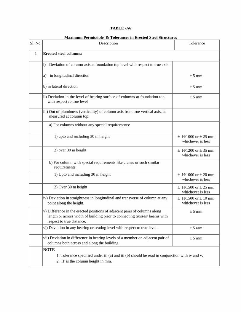
TABLE -A6
Maximum Permissible & Tolerances in Erected Steel Structures
Sl. No.
Description Tolerance
1 Erected steel columns:
i) Deviation of column axis at foundation top level with respect to true axis: a) in longitudinal direction b) in lateral direction
± 5 mm
± 5 mm
ii) Deviation in the level of bearing surface of columns at foundation top with respect to true level
± 5 mm
iii) Out of plumbness (verticality) of column axis from true vertical axis, as measured at column top:
a) For columns without any special requirements:
1) upto and including 30 m height
± H/1000 or ± 25 mm whichever is less
2) over 30 m height
± H/1200 or ± 35 mm whichever is less
b) For column with special requirements like cranes or such similar requirements:
1) Upto and including 30 m height
± H/1000 or ± 20 mm whichever is less
2) Over 30 m height ± H/1500 or ± 25 mm whichever is less
iv) Deviation in straightness in longitudinal and transverse of column at any point along the height.
± H/1500 or ± 10 mm whichever is less
v) Difference in the erected positions of adjacent pairs of columns along length or across width of building prior to connecting trusses/ beams with respect to true distance.
± 5 mm
vi) Deviation in any bearing or seating level with respect to true level. ± 5 ram
vii) Deviation in difference in bearing levels of a member on adjacent pair of columns both across and along the building.
± 5 mm
NOTE 1. Tolerance specified under iii (a) and iii (b) should be read in conjunction with iv and v. 2. 'H' is the column height in mm.

TABLE- 6 (Contd.)
S. No. Description Tolerance
Erected Steel trusses
i) Shift, at the centre of span of top chord member with respect to the vertical plane passing through the centre of bottom chord.
± 1/250 of height of truss in mm at centre of span or ± 15 mm Whichever is less
ii) Lateral shift of top chord of truss at the centre of span from the vertical plane passing through the centre of supports of the truss
± 1/1500 of span of truss in mm or 10 mm whichever is less
iii) Lateral shift in location of truss from its true axis in plan
± 10 mm
iv) Lateral shift in location of purlin From true position ± 5 mm
2.0
v) Deviation in difference or bearing levels of trusses from the true difference.
± 1/1200 of span of truss in mm or ± 20 mm whichever is less
Erected Crane Girder and Rails
i) Shift in the centre line of crane rail with respect to centre line of web crane girder.
± {(Web thk in mm) + 2mm} / 2
ii) Shift in plan of alignment of crane rail with respect to true axis of crane rail at any point,
± 5 mm
iii) Deviation in crane track gauge with respect to the gauges
a) For track gauge up to and including 15 mm + 5 mm
b) For track gauge more than 15 m
± (5 + 0.25(S-15)) mm subject to a maximum of ±10 mm, where S in meters is true track gauge.
iv) Deviation in the crane rail level at any point from true level ± 10 mm
v) Difference in levels between crane track rails at:
a) Supports of crane girders 15 mm
b) mid span of crane girders 20 mm
3.
vi) Relative shift of crane rail surface at a joint in plan and elevation.
2 mm subject to grinding of surfaces for smooth transition
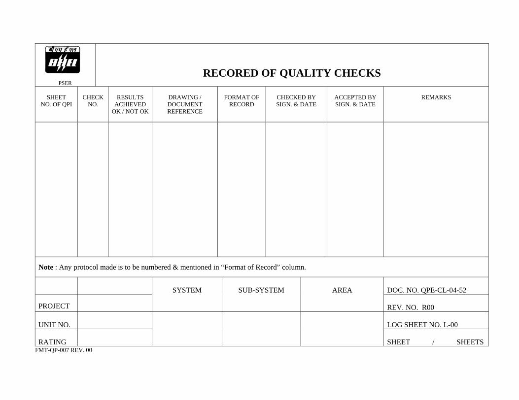
PSER
RECORED OF QUALITY CHECKS
SHEET NO. OF QPI
CHECK
NO.
RESULTS
ACHIEVED OK / NOT OK
DRAWING / DOCUMENT REFERENCE
FORMAT OF
RECORD
CHECKED BY SIGN. & DATE
ACCEPTED BY SIGN. & DATE
REMARKS
Note : Any protocol made is to be numbered & mentioned in “Format of Record” column.
DOC. NO. QPE-CL-04-52
PROJECT
SYSTEM
SUB-SYSTEM
AREA
REV. NO. R00
UNIT NO.
LOG SHEET NO. L-00
RATING
SHEET / SHEETS
FMT-QP-007 REV. 00
INSTRUMENT REG. NO.
DATE OF INSPECTION
PSER
DRAWING / DOCUMENT REF.
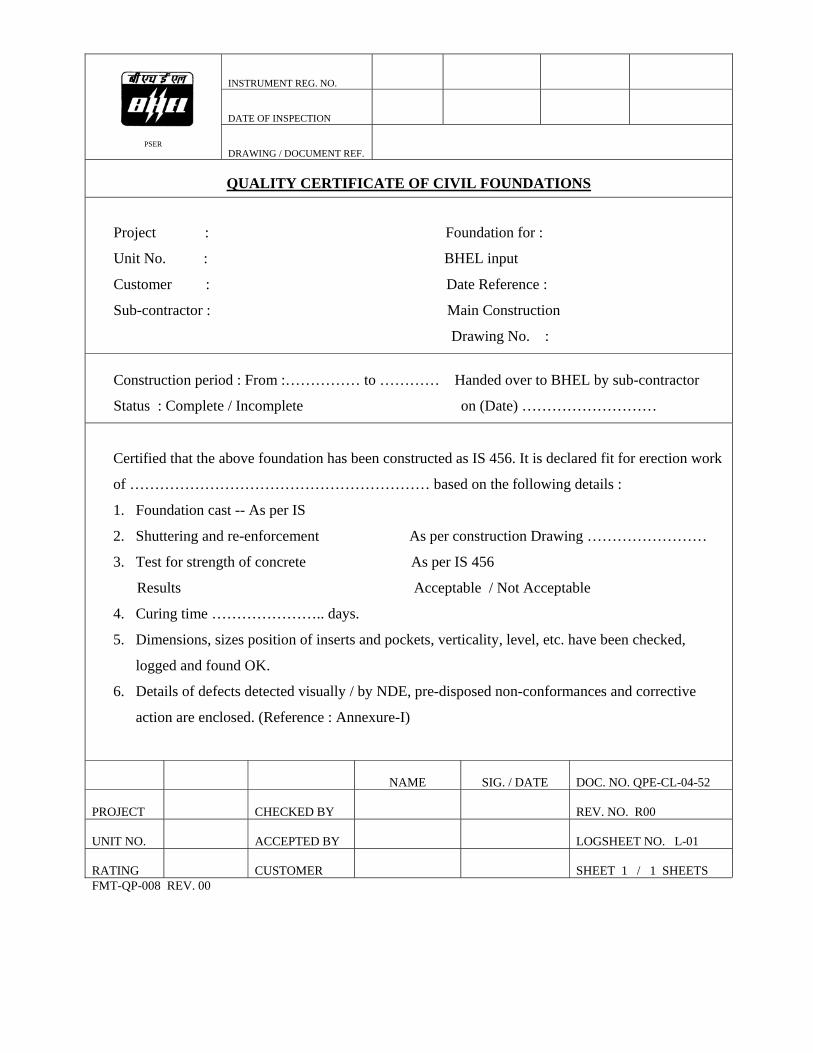
QUALITY CERTIFICATE OF CIVIL FOUNDATIONS
Project : Foundation for :
Unit No. : BHEL input
Customer : Date Reference :
Sub-contractor : Main Construction
Drawing No. :
Construction period : From :…………… to ………… Handed over to BHEL by sub-contractor
Status : Complete / Incomplete on (Date) ………………………
Certified that the above foundation has been constructed as IS 456. It is declared fit for erection work
of …………………………………………………… based on the following details :
1. Foundation cast -- As per IS
2. Shuttering and re-enforcement As per construction Drawing ……………………
3. Test for strength of concrete As per IS 456
Results Acceptable / Not Acceptable
4. Curing time ………………….. days.
5. Dimensions, sizes position of inserts and pockets, verticality, level, etc. have been checked,
logged and found OK.
6. Details of defects detected visually / by NDE, pre-disposed non-conformances and corrective
action are enclosed. (Reference : Annexure-I)
NAME
SIG. / DATE DOC. NO. QPE-CL-04-52
PROJECT
CHECKED BY
REV. NO. R00
UNIT NO.
ACCEPTED BY
LOGSHEET NO. L-01
RATING
CUSTOMER
SHEET 1 / 1 SHEETS
FMT-QP-008 REV. 00

INSTRUMENT REG. NO.
DATE OF INSPECTION
PSER
DRAWING / DOCUMENT REF.
FOUNDATION - POWER HOUSE STRUCTURE
TOP OF PEDESTALS
Elevation of top pedestal as per drawing …………………… mm.
All dimensions are in mm.Column No. Top Elevation
measurement Deviation from drawing value
Column No. Top Elevation measurement
Deviation from drawing value
NAME
SIG. / DATE DOC. NO. QPE-CL-04-52
PROJECT
CHECKED BY
REV. NO. R00
UNIT NO.
ACCEPTED BY
LOGSHEET NO. L-02
RATING
CUSTOMER
SHEET 1 / 1 SHEETS
FMT-QP-008 REV. 00

INSTRUMENT REG. NO.
DATE OF INSPECTION
PSER
DRAWING / DOCUMENT REF.
FOUNDATION - POWER HOUSE STRUCTURE
COLUMN PEDESTALS SPACING
All dimensions are in mm. Column No. Spacing Column No. Spacing
From To Drawing Actual From To Drawing Actual
NAME
SIG. / DATE
DOC. NO. QPE-CL-04-52
PROJECT
CHECKED BY
REV. NO. R00
UNIT NO.
ACCEPTED BY
LOGSHEET NO. L-03
RATING
CUSTOMER
SHEET 1 / 1 SHEETS
FMT-QP-008 REV. 00

INSTRUMENT REG. NO.
DATE OF INSPECTION
PSER
DRAWING / DOCUMENT REF.
FOUNDATION - POWER HOUSE STRUCTURE
DIAGONAL BETWEEN COLUMN PEDESTALS
All dimensions are in mm.
Column No. Diagonal D1 Column No. Diagonal
D2 Difference between
D1 & D2 From To From To
NAME
SIG. / DATE DOC. NO. QPE-CL-04-52
PROJECT
CHECKED BY
REV. NO. R00
UNIT NO.
ACCEPTED BY
LOGSHEET NO. L-04
RATING
CUSTOMER
SHEET 1 / 1 SHEETS
FMT-QP-008 REV. 00

INSTRUMENT REG. NO.
DATE OF INSPECTION
PSER
DRAWING / DOCUMENT REF.
PITCH DISTANCE OF FOUNDATION BOLTS & DIAGONALS
N . TYPE -I TYPE -II
TYPE - I
Column No. A B a1 a2 1 2 3 4 1' 2' 3' 4' D1 D2
As per drawing TYPE - II
Column No. A B a1 a2 1 2 3 4 1' 2' 3' 4' D1 D2 As per drawing
NAME
SIG. / DATE DOC. NO. QPE-CL-04-52
PROJECT
CHECKED BY
REV. NO. R00
UNIT NO.
ACCEPTED BY
LOGSHEET NO. L-05
RATING
CUSTOMER
SHEET 1 / 4 SHEETS
FMT-QP-008 REV. 00

INSTRUMENT REG. NO.
DATE OF INSPECTION
PSER
DRAWING / DOCUMENT REF.
PITCH DISTANCE OF FOUNDATION BOLTS & DIAGONALS
N TYPE - III
Column No. A B a1 a2 1 2 3 4 1' 2' 3' 4' D1 D2 As per drawing
NAME
SIG. / DATE DOC. NO. QPE-CL-04-52
PROJECT
CHECKED BY
REV. NO. R00
UNIT NO.
ACCEPTED BY
LOGSHEET NO. L-05
RATING
CUSTOMER
SHEET 2 / 4 SHEETS
FMT-QP-008 REV. 00

INSTRUMENT REG. NO.
DATE OF INSPECTION
PSER
DRAWING / DOCUMENT REF.
PITCH DISTANCE OF FOUNDATION BOLTS & DIAGONALS
Type IV
N Type - IV
Column No. A B a1 a2 a3 a4 1 2 3 4 1' 2' 3' 4' D1 D2 As per drawing
NAME
SIG. / DATE DOC. NO. QPE-CL-04-52
PROJECT
CHECKED BY
REV. NO. R00
UNIT NO.
ACCEPTED BY
LOGSHEET NO. L-05
RATING
CUSTOMER
SHEET 3 / 4 SHEETS
FMT-QP-008 REV. 00
INSTRUMENT REG. NO.
DATE OF INSPECTION
PSER
DRAWING / DOCUMENT REF.
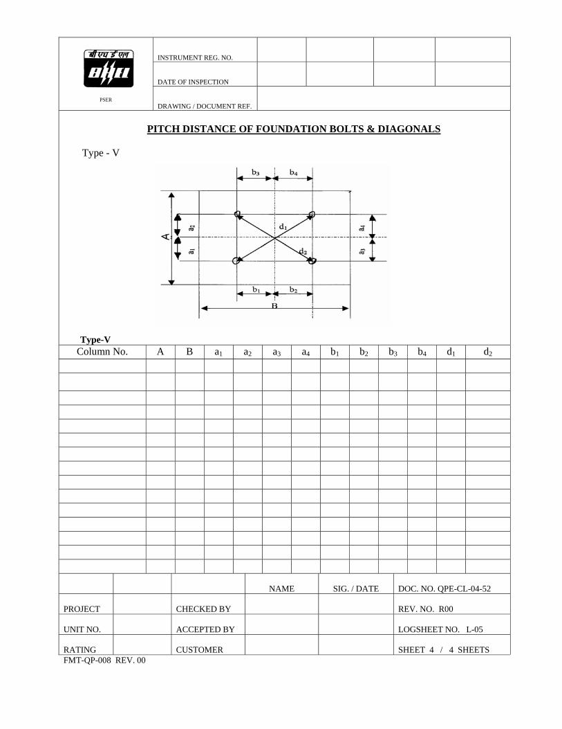
PITCH DISTANCE OF FOUNDATION BOLTS & DIAGONALS
Type - V
Type-V
Column No. A B a1 a2 a3 a4 b1 b2 b3 b4 d1 d2
NAME
SIG. / DATE
DOC. NO. QPE-CL-04-52
PROJECT
CHECKED BY
REV. NO. R00
UNIT NO.
ACCEPTED BY
LOGSHEET NO. L-05
RATING
CUSTOMER
SHEET 4 / 4 SHEETS
FMT-QP-008 REV. 00

INSTRUMENT REG. NO./TAG NO.
DATE OF INSPECTION
PSER
DRAWING / DOCUMENT REF.
CAMBER, SWEEP AND LENGTH OF COLUMN PIECES
INDIVIDUAL PIECE TOLERANCE : 1mm / M Max. 10 mm
Column No. Camber Sweep Length
Piece No. T M B T M B
T – Top of the Piece M – Middle of the Piece B – Bottom of the Piece
NAME
SIG./DATE DOC. NO. QPE-CL-04-52
PROJECT
CHECKED BY
REV. NO. R 00
UNIT NO.
ACCEPTED BY
LOG SHEET NO. L-06
RATING
CUSTOMER
SHEET 1 / 1 SHEETS
FMT-QP-008 REV.00
INSTRUMENT REG. NO.
DATE OF INSPECTION
PSER
DRAWING / DOCUMENT REF.
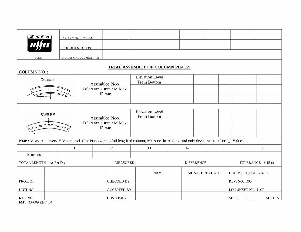
TRIAL ASSEMBLY OF COLUMN PIECES
COLUMN NO. : Elevation Level From Bottom
Assembled Piece
Tolerance 1 mm / M Max. 15 mm
Elevation Level From Bottom
Assembled Piece Tolerance 1 mm / M Max.
15 mm
Note : Measure at every 5 Meter level. (Fix Piano wire to full length of column) Measure the reading and only deviation in "+" or "_" Values
J1 J2 J3 J4 J5 J6
Match mark
TOTAL LENGTH : As Per Drg. MEASURED : DIFFERENCE : TOLERANCE : ± 15 mm
NAME
SIGNATURE / DATE
DOC. NO. QPE-CL-04-52
PROJECT
CHECKED BY
REV. NO. R00
UNIT NO.
ACCEPTED BY
LOG SHEET NO. L-07
RATING
CUSTOMER
SHEET 1 / 1 SHEETS
FMT-QP-009 REV. 00
INSTRUMENT REG. NO./TAG NO.
DATE OF INSPECTION
PSER
DRAWING / DOCUMENT REF.
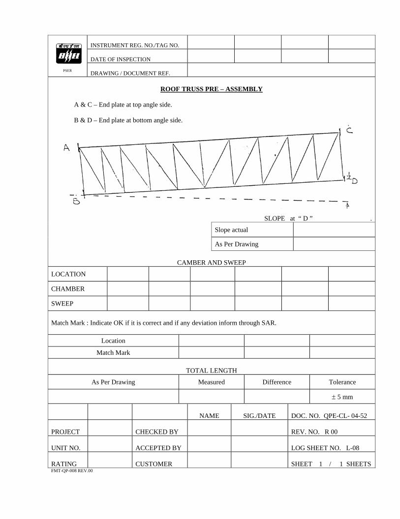
ROOF TRUSS PRE – ASSEMBLY
A & C – End plate at top angle side. B & D – End plate at bottom angle side.
SLOPE at “ D ” .
Slope actual
As Per Drawing
CAMBER AND SWEEP
LOCATION
CHAMBER
SWEEP
Match Mark : Indicate OK if it is correct and if any deviation inform through SAR.
Location
Match Mark
TOTAL LENGTH
As Per Drawing Measured Difference Tolerance
± 5 mm
NAME
SIG./DATE DOC. NO. QPE-CL- 04-52
PROJECT
CHECKED BY
REV. NO. R 00
UNIT NO.
ACCEPTED BY
LOG SHEET NO. L-08
RATING
CUSTOMER
SHEET 1 / 1 SHEETS
FMT-QP-008 REV.00
INSTRUMENT REG. NO./TAG NO.
DATE OF INSPECTION
PSER
DRAWING / DOCUMENT REF.
GROUTING GAP
(All Measurements in mm) Column No. Column No. Column No.
NAME
SIG./DATE DOC. NO. QPE-CL-04-52
PROJECT
CHECKED BY
REV. NO. R 00
UNIT NO.
ACCEPTED BY
LOG SHEET NO. L-09
RATING
CUSTOMER
SHEET 1 / 1 SHEETS
FMT-QP-008 REV.00
INSTRUMENT REG. NO./TAG NO.
DATE OF INSPECTION
PSER
DRAWING / DOCUMENT REF.
COLUMN VERTICALITY MEASUREMENT
(Note :To be checked with theodolite and cross checked with plumb bob.)
(All Measurements in mm)
Column No. Inclined to wards Column
No. Inclined towards
Location Left Right Front Rear Location Left Right Front Rear
(Tolerance 1 mm / Meter Max. 25 mm)
NAME
SIG./DATE DOC. NO. QPE-CL-04-52
PROJECT
CHECKED BY
REV. NO. R 00
UNIT NO.
ACCEPTED BY
LOG SHEET NO. L-10
RATING
CUSTOMER
SHEET 1 / 1 SHEETS
FMT-QP-008 REV.00

INSTRUMENT REG. NO./TAG NO.
DATE OF INSPECTION
PSER
DRAWING / DOCUMENT REF.
CRANE GIRDER
Crane girder bracket top level Crane girder top flange level Column
No. Level Column No. Level Column
No. Level Column
No. Level
Tolerance Max. 5 mm All Dimension in mm.
NAME
SIG./DATE
DOC. NO. QPE-CL-04-52
PROJECT
CHECKED BY
REV. NO. R 00
UNIT NO.
ACCEPTED BY
LOG SHEET NO. L-11
RATING
CUSTOMER
SHEET 1 / 1 SHEETS
FMT-QP-008 REV.00
INSTRUMENT REG. NO./TAG NO.
DATE OF INSPECTION
PSER
DRAWING / DOCUMENT REF.
CRANE GIRDER CENTER TO CENTER SPACING
Tolerances : ± 5 mm
All dimensions in mm.
Location Measured Length Deviation Location Measured
Length Deviation
NAME
SIG./DATE
DOC. NO. QPE-CL-04-52
PROJECT
CHECKED BY
REV. NO. R 00
UNIT NO.
ACCEPTED BY
LOG SHEET NO. L-12
RATING
CUSTOMER
SHEET 1 / 1 SHEETS
FMT-QP-008 REV.00

QUALITY PLAN FOR INSTALLATION
BOILER
STRUCTURES (Erection)
FOR
MEJIA TPS EXTN. (UNITS 5 & 6) 2 x 250 MW
(M/s. Damodar Valley Corporation)
BHARAT HEAVY ELECTRICALS LIMITED POWER SECTOR EASTERN REGION
DOC. NO. : QPE-BR-04-55 REV. NO. : R00
FMT-QP-001 Rev.01

QUALITY PLAN FOR INSTALLATION
BOILER
STRUCTURES
(Erection)
MEJIA TPS EXTN. ( UNITS 5 & 6 ) 2 x 250 MW
(M/s. Damodar Valley Corporation)
PREPARED BY
SR MANAGER/QLY,PSER APPROVED BY HEAD/QLY, PSER
DOCUMENT NO. QPE-BR-04-55
ORIGINAL DATE OF ISSUE 20.08.2004
REVISION NO. & DATE R00Dt. 20.08.2004
COPY NO.
ISSUED TO
DATE OF ISSUE
CONTROLLED / INFORMATION COPY
ISSUED BY (SIGNATURE & DESIGNATION)
BHARAT HEAVY ELECTRICALS LIMITED POWER SECTOR EASTERN REGION
FMT-QP-002 Rev. 01
DOC. NO. : QPE-BR-04-55
REV. NO. : R00
PSER
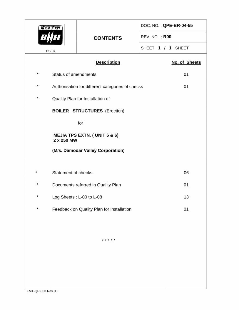
CONTENTS
SHEET 1 / 1 SHEET
Description No. of Sheets * Status of amendments 01 * Authorisation for different categories of checks 01 * Quality Plan for Installation of BOILER STRUCTURES (Erection) for MEJIA TPS EXTN. ( UNIT 5 & 6)
2 x 250 MW
(M/s. Damodar Valley Corporation)
* Statement of checks 06 * Documents referred in Quality Plan 01 * Log Sheets : L-00 to L-08 13 * Feedback on Quality Plan for Installation 01
* * * * *
FMT-QP-003 Rev.00
DOC. NO. : QPE-BR-04-55
REV. NO. : R00
PSER
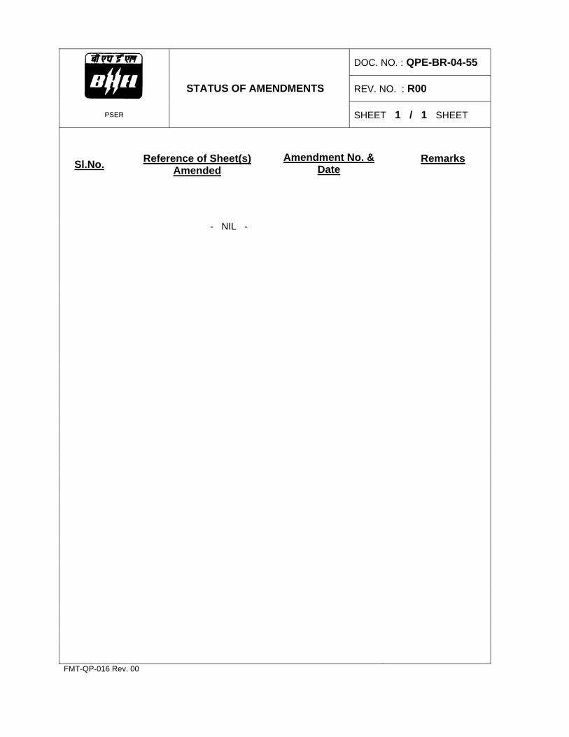
STATUS OF AMENDMENTS
SHEET 1 / 1 SHEET
Sl.No.
Reference of Sheet(s) Amended
Amendment No. & Date
Remarks
- NIL -
FMT-QP-016 Rev. 00
PSER
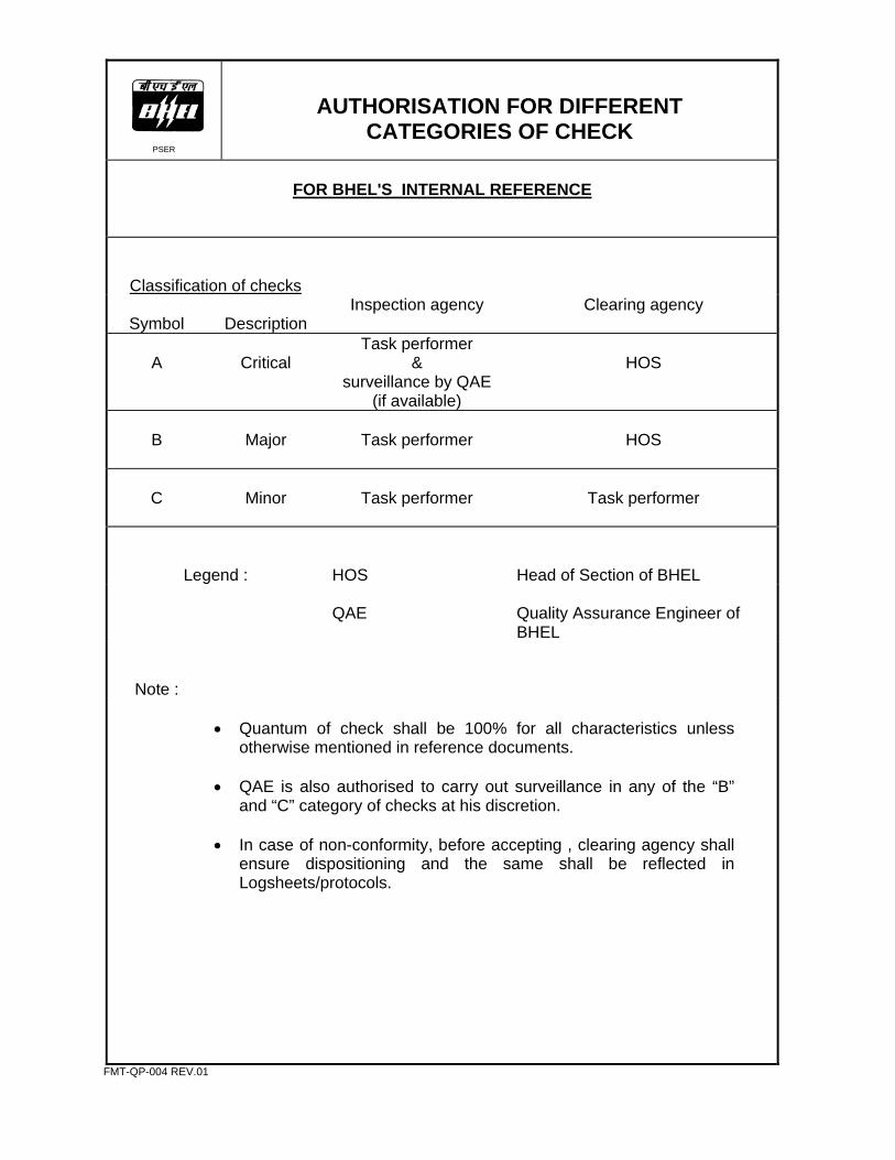
AUTHORISATION FOR DIFFERENT CATEGORIES OF CHECK
FOR BHEL'S INTERNAL REFERENCE
Classification of checks
Symbol
Description
Inspection agency Clearing agency
A
Critical
Task performer &
surveillance by QAE (if available)
HOS
B
Major
Task performer
HOS
C
Minor
Task performer
Task performer
Legend :
HOS
Head of Section of BHEL
QAE Quality Assurance Engineer of BHEL
Note :
• Quantum of check shall be 100% for all characteristics unless
otherwise mentioned in reference documents. • QAE is also authorised to carry out surveillance in any of the “B”
and “C” category of checks at his discretion. • In case of non-conformity, before accepting , clearing agency shall
ensure dispositioning and the same shall be reflected in Logsheets/protocols.
FMT-QP-004 REV.01
PSER
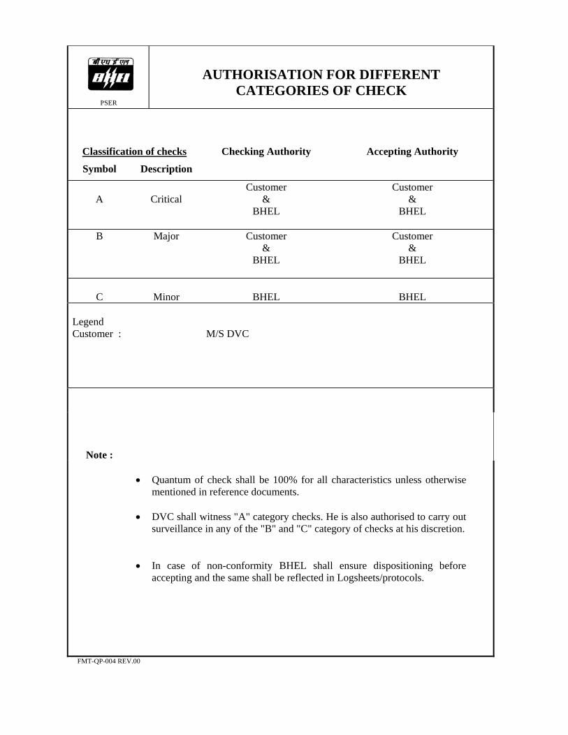
AUTHORISATION FOR DIFFERENT CATEGORIES OF CHECK
Classification of checks
Checking Authority
Accepting Authority
Symbol Description
A
Critical
Customer &
BHEL
Customer &
BHEL
B Major Customer &
BHEL
Customer &
BHEL
C
Minor
BHEL
BHEL
Legend Customer :
M/S DVC
Note :
• Quantum of check shall be 100% for all characteristics unless otherwise
mentioned in reference documents. • DVC shall witness "A" category checks. He is also authorised to carry out
surveillance in any of the "B" and "C" category of checks at his discretion. • In case of non-conformity BHEL shall ensure dispositioning before
accepting and the same shall be reflected in Logsheets/protocols.
FMT-QP-004 REV.00


DOC. NO. : QPE-BR-04-55
REV. NO. : R00
PSER
STATEMENT OF CHECKS
SHEET 1 / 6 SHEETS
Capacity / Type : 2 x 250 MW
System : BOILER
Sub-System : STRUCTURES
Area : ERECTION * For checks where log sheets are not called for, suitable records shall be
maintained in the form of log book / protocols.
* As an evidence of having carried out the work satisfactorily, a general-purpose log sheet L-00 shall be maintained for all the checks.
* Abbreviations used in the column “Type of Check” are: R : Record Verification M : Measurement V : Visual T : Test
FMT-QP-005 Rev. 00

DOC.NO.: QPE-BR-04-55
REV.NO.: R00
PSER
STATEMENT OF CHECKS
SHEET 2 / 6 SHEETS SYSTEM : BOILER SUB-SYSTEM : STRUCTURES AREA : ERECTION
SL NO. CHARACTERISTICS / ITEM TYPE
OF CHECK
INSTRUMENT CLASSQUANTUM/
FREQUENCY OF CHECK
REFERENCE DOCUMENT/ ACCEPTANCE STANDARD
FORMAT OF
RECORDREMARKS
FOUNDATION :
1. Availability of identified & protected permanent benchmark. V B 100% Relevant Drawing
2. Elevation of top of foundation pedestals w.r.t. permanent bench mark.
M Dumpy level / Water level /
Tape
A 100% - do - L - 01
3. Disposition of foundation pedestals w.r.t. longitudinal axis of boiler and reference axis.
M Tape A 100% - do - L - 02
4. Spacing between the foundation pedestals. M Tape B 100% - do - L - 02
5. Diagonals of the main column foundation pedestals. M Tape B 100% - do - L - 03
6. Pitch distance of foundation pedestal bolts on both the axes and its diagonals.
M Tape C 100% - do - L - 04
STRUCTURES :
1. Pre-assembly of columns before erection, wherever applicable. V/M Tape / Piano wire / Water level
B 100% - do -
2. Individual column piece camber and sweep
(Tolerance : 1 mm / M ; 10 mm max.). M - do - B 100% - do -
FMT-QP-006 REV.01

DOC.NO.: QPE-BR-04-55
REV.NO.: R00
PSER
STATEMENT OF CHECKS
SHEET 3 / 6 SHEETS SYSTEM : BOILER SUB-SYSTEM : STRUCTURES AREA : ERECTION
SL NO. CHARACTERISTICS / ITEM TYPE
OF CHECK
INSTRUMENT CLASSQUANTUM/
FREQUENCY OF CHECK
REFERENCE DOCUMENT/ ACCEPTANCE STANDARD
FORMAT OF
RECORDREMARKS
3. Camber and sweep for assembled columns
(Tolerance : 1 mm / M ; 18 mm max.). M Tape /
Piano wire / Water level
B 100% Relevant Drawing
4. Total length of column before erection
(Tolerance : ± 15 mm ). M Tape B 100% - do -
5. Orientation of columns. Check for match mark, elevation
mark, column No., splice size etc. V B 100% - do -
6. Ensure matching of centre line of base plate with pedestal
axes. V B 100% - do -
7. Elevation of column at 1 metre level with reference to bench
mark (Tolerance : ± 5 mm ). M Water level /
Tape B 100% - do -
8. Alignment of first piece of column with horizontal beams and
vertical bracings (Tolerance : Position w.r.t. reference axis : ± 5 mm ; elevation : ± 5 mm).
M Theodolite / Tape /
Plumb bob
B 100% - do - L-06
9. Completion of boxes with main brace level members (MBL). V - do -
10. Grouting gap below the column base (Max. 70 mm ).
M Tape B 100% - do -
11. Verification of test certificates and batch certificates of grout
material. V A 100% Work Instruction
for Grouting
FMT-QP-006 REV.01
DOC.NO.: QPE-BR-04-55
REV.NO.: R00
PSER
STATEMENT OF CHECKS
SHEET 4 / 6 SHEETS SYSTEM : BOILER SUB-SYSTEM : STRUCTURES AREA : ERECTION
SL NO. CHARACTERISTICS / ITEM TYPE
OF CHECK
INSTRUMENT CLASSQUANTUM/
FREQUENCY OF CHECK
REFERENCE DOCUMENT/ ACCEPTANCE STANDARD
FORMAT OF
RECORDREMARKS
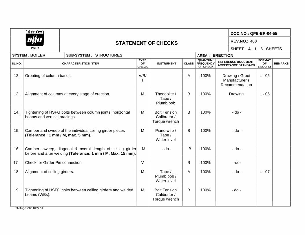
12. Grouting of column bases. V/R/
T A 100% Drawing / Grout
Manufacturer’s Recommendation
L - 05
13. Alignment of columns at every stage of erection. M Theodolite /
Tape / Plumb bob
B 100% Drawing L - 06
14. Tightening of HSFG bolts between column joints, horizontal
beams and vertical bracings. M Bolt Tension
Calibrator / Torque wrench
B 100% - do -
15. Camber and sweep of the individual ceiling girder pieces
(Tolerance : 1 mm / M, max. 5 mm). M Piano wire /
Tape / Water level
B 100% - do -
16. Camber, sweep, diagonal & overall length of ceiling girder
before and after welding (Tolerance: 1 mm / M, Max. 15 mm).M - do - B 100% - do -
17 Check for Girder Pin connection V B 100% -do-
18. Alignment of ceiling girders. M Tape /
Plumb bob / Water level
A 100% - do - L - 07
19. Tightening of HSFG bolts between ceiling girders and welded
beams (WBs). M Bolt Tension
Calibrator / Torque wrench
B 100% - do -
FMT-QP-006 REV.01

DOC.NO.: QPE-BR-04-55
REV.NO.: R00
PSER
STATEMENT OF CHECKS
SHEET 5 / 6 SHEETS SYSTEM : BOILER SUB-SYSTEM : STRUCTURES AREA : ERECTION
SL NO. CHARACTERISTICS / ITEM TYPE
OF CHECK
INSTRUMENT CLASSQUANTUM/
FREQUENCY OF CHECK
REFERENCE DOCUMENT/ ACCEPTANCE STANDARD
FORMAT OF
RECORDREMARKS
20. Verticality of columns before and after ceiling girder erection,
at every 5M and at column erection joints. (Tolerance : 1 mm /M ; or 25 mm whichever is less)
M Theodolite / Plumb bob /
Tape
A 100% Relevant Drawing L - 06
21. Centre line of ceiling girders marked w.r.t. the longitudinal
axis of boiler transferred from ground level to top. (Tolerance : +/- 5 mm)
M Theodolite / Tape
A 100% - do - L - 07
22. Check for welding completion of MBL V A 100% -do-
23. Readiness of structure for drum erection. V A 100% - do - L - 08
24. Ensure completion of stair case with hand rails up to drum
level V B 100% -do-
25. Clearance of milestone activity. V A 100%
26. Verticality of all main columns (wherever possible)
immediately after drum lifting and compare with previous values.
M Theodolite / Plumb bob /
Tape
A 100% - do - L - 06
27. Removal of temporary supports. V C 100%
FMT-QP-006 REV.01

DOC.NO.: QPE-BR-04-55
REV.NO.: R00
PSER
STATEMENT OF CHECKS
SHEET 6 / 6 SHEETS SYSTEM : BOILER SUB-SYSTEM : STRUCTURES AREA : COMMISSIONING
SL NO. CHARACTERISTICS / ITEM TYPE
OF CHECK
INSTRUMENT CLASSQUANTUM/
FREQUENCY OF CHECK
REFERENCE DOCUMENT/ACCEPTANCE STANDARD
FORMAT OF
RECORDREMARKS
WELDING & NDE : 1. Qualification of welders. V/R A 100% Welding Manual
2. Availability of approved WPS, Heat Treatment Schedule,
Erection Manual, Storage Manual, Calibration test certificates of instruments used.
R A 100%
3. Pre heating of weld joints. V/M Time
Temperature Recorder /
Thermal Chalk
B As per Reference Document
Drawing / Heat Treatment Manual
4. Adoption of correct procedure, approved electrodes and methods.
V/R B 100% Drawing / Welding Manual / Heat Treatment
Manual
5. NDE of site welds. V/T B 100% NDE Manual 7. Stress relieving of Ceiling Girder R B 100% Heat Treatment
Manual
8 CLEANING AND PAINTING: 8.1 Ensure that the surface are cleaned and painted as specified V C 100% Drawing
8.2 Ensure that the following markings are done V C 100% Drawing
a)Assemblies designation b)Part Number c)Any other important identifications
8.3 Ensure Dry Film Thickness of paint is as per specification M B 100% Specification
FMT-QP-006 REV.01
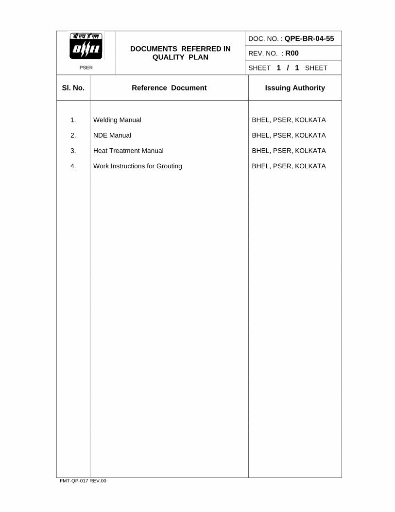
DOC. NO. : QPE-BR-04-55
REV. NO. : R00
PSER
DOCUMENTS REFERRED IN QUALITY PLAN
SHEET 1 / 1 SHEET
Sl. No.
Reference Document
Issuing Authority
1. Welding Manual BHEL, PSER, KOLKATA
2. NDE Manual BHEL, PSER, KOLKATA
3. Heat Treatment Manual BHEL, PSER, KOLKATA
4. Work Instructions for Grouting BHEL, PSER, KOLKATA
FMT-QP-017 REV.00

PSER
RECORD OF QUALITY CHECKS
SHEET
NO. OF QPI
CHECK
NO.
RESULTS ACHIEVED
OK / NOT OK
DRAWING / DOCUMENT REFERENCE
FORMAT OF
RECORD
INSPECTED BY SIGN. & DATE
CLEARED BY SIGN. & DATE
REMARKS
Note : Any protocol made is to be numbered & mentioned in “Format of Record” column. DOC. NO. : QPE-BR-04-55 PROJECT SYSTEM SUB-SYSTEM AREA
REV. NO. : R00 UNIT NO. LOG SHEET NO. : L-00 RATING
SHEET 1 / 1 SHEET FMT-QP-007 REV. 01

INSTRUMENT REGN.NO.
DATE OF INSPECTION
PSER
DRAWING / DOCUMENT REF.
BOILER FOUNDATIONS TOP OF PEDESTAL
Top elevation of pedestals as per drawing _______ mm
Tolerance : * - 20 mm All dimensions are in mm
Sl, No.
Pedestal Designation
Top Elevation
Sl. No.
Pedestal Designation
Top Elevation
1 S1L 16 S6R
2 S2L 17 S7R
3 S3L 18 S8R
4 S4L 19 S9R
5 S5L 20 S10R
6 S6L 21 S11
7 S7L 22 S12
8 S8L 23 S13
9 S9L 24 S14
10 S10L 25 S15
11 S1R 26 S16
12 S2R 27 S17L
13 S3R 28 S18L
14 S4R 29 S17R
15 S5R 30 S18R
* Positive tolerance or top of pedestals to be chipped off so that thickness of grouting as shown in relevant drawing can be provided. NAME SIGNATURE & DATE DOC. NO.:QPE-BR-04-55PROJECT INSPECTED BY REV.NO.: R00
UNIT NO. CLEARED BY LOG SHEET NO.: L-01
RATING CUSTOMER SHEET 1 / 1 SHEET FMT-QP-008 REV.01
INSTRUMENT REGN.NO. DATE OF INSPECTION
PSER
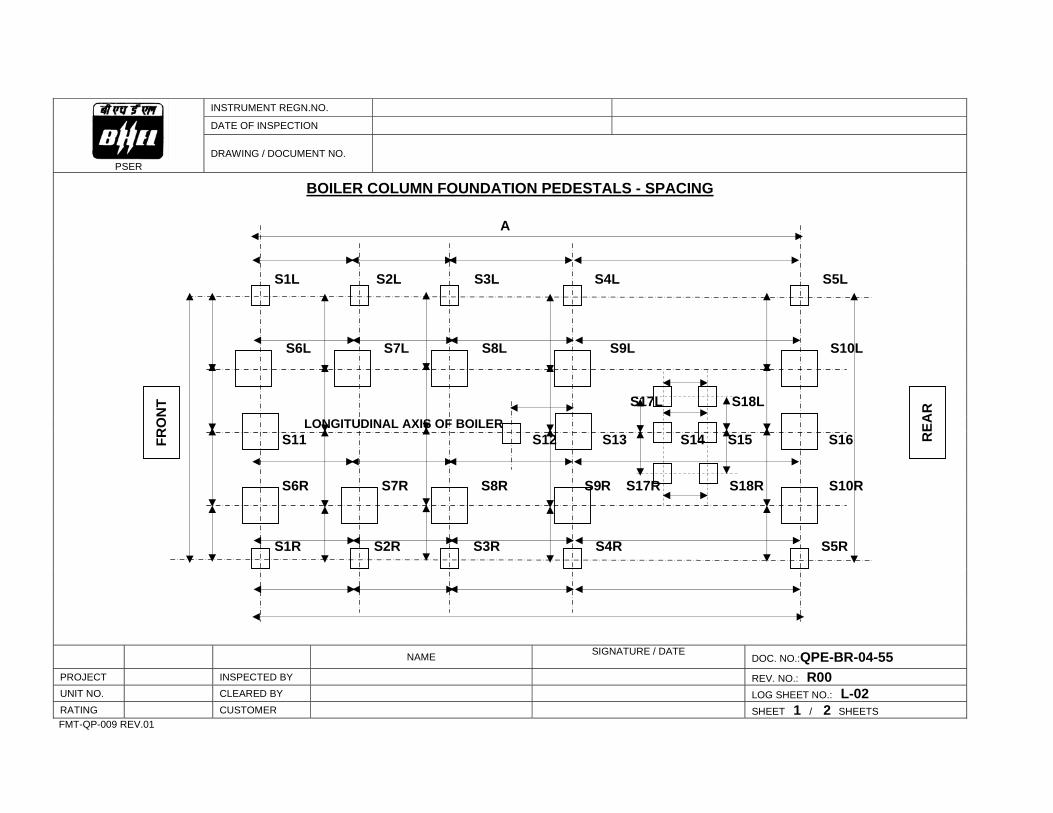
DRAWING / DOCUMENT NO.
BOILER COLUMN FOUNDATION PEDESTALS - SPACING
A
S1L S2L S3L S4L S5L
S6L S7L S8L S9L S10L
S17L S18L LONGITUDINAL AXIS OF BOILER S11 S12 S13 S14 S15 S16 S6R S7R S8R S9R S17R S18R S10R
S1R S2R S3R S4R S5R
NAME SIGNATURE / DATE DOC. NO.:QPE-BR-04-55
PROJECT INSPECTED BY REV. NO.: R00 UNIT NO. CLEARED BY LOG SHEET NO.: L-02 RATING CUSTOMER SHEET 1 / 2 SHEETS
FMT-QP-009 REV.01
REA
R
FRO
NT

INSTRUMENT REGN.NO.
DATE OF INSPECTION
PSER
DRAWING / DOCUMENT REF.
BOILER COLUMN FOUNDATION PEDESTALS - SPACING
Sl.No. Spacing Between
As per drawing Actual Sl.No. Spacing
Between As per
drawing Actual
1 S1L & S2L 29 S5L & S10L
2 S2L & S3L 30 S6L & BA
3 S3L & S4L 31 S7L & BA
4 S4L & S5L 32 S8L & BA
5 S6L & S7L 33 S9L & BA
6 S7L & S8L 34 S17L & BA
7 S8L & S9L 35 S18L & BA
8 S9L & S10L 36 S1OL & BA
9 S11 & S12 37 BA & S6R
10 S12 & S13 38 BA & S7R
11 S13 & S14 39 BA & S8R
12 S14 & S15 40 BA & S9R
13 S15 & S16 41 BA & S17R
14 S17L & S18L 42 BA &S18R
15 S1R & S2R 43 BA &S10R
16 S2R & S3R 44 S6R & S1R
17 S3R & S4R 45 S7R & S2R
18 S4R & S5R 46 S8R & S3R
19 S5R & S6R 47 S9R & S4R
20 S6R & S7R 48 S10R & S5R
21 S7R & S8R 49 S1L & S5L
22 S8R & S9R 50 S1R & S5R
23 S9R & S10R 51 S1L & S1R
24 S17R & S18R 52 S5L & S5R
25 S1L & S6L
26 S2L & S7L
27 S3L & S8L
28 S4L & S9L Tolerances: 1. Between adjacent foundation pedestals centres: 1 mm / M, ± 5 mm max. 2. Spacing between first and last row of foundation: 1 mm / M, ± 15 mm max. All dimensions are in mm. NAME SIGNATURE & DATE DOC. NO.:QPE-BR-04-55PROJECT INSPECTED BY REV.NO.: R00
UNIT NO. CLEARED BY LOG SHEET NO.: L-02
RATING CUSTOMER SHEET 2 / 2 SHEETS FMT-QP-008 REV.01

INSTRUMENT REGN.NO. DATE OF INSPECTION
PSER
DRAWING / DOCUMENT NO.
DIAGONAL CHECK BETWEEN MAIN COLUMN FOUNDATION PEDESTALS
S1L S2L S3L S4L S5L
S6L S7L S8L S9L S10L
S17L S18L LONGITUDINAL AXIS OF BOILER S11 S12 S13 S14 S15 S16 S6R S7R S8R S9R S17R S18R S10R
S1R S2R S3R S4R S5R
NAME SIGNATURE / DATE DOC. NO.:QPE-BR-04-55
PROJECT INSPECTED BY REV. NO.: R00 UNIT NO. CLEARED BY LOG SHEET NO.: L-03 RATING CUSTOMER SHEET 1 / 2 SHEETS
FMT-QP-009 REV.01
REA
R
FRO
NT

INSTRUMENT REGN.NO.
DATE OF INSPECTION
PSER
DRAWING / DOCUMENT REF.
DIAGONAL CHECK BETWEEN MAIN COLUMN FOUNDATION PEDESTALS
Sl.No. Diagonal between
Measure-ment Difference Sl.No. Diagonal
between Measure-
ment Difference
1 S6L & S7R 11 S7L & S9R
2 S6R & S7L
12 S7R & S9L
3 S7L & S8R 13 S8L & S10R
4 S7R & S8L
14 S8R & S10L
5 S8L & S9R
6 S8R & S9L
7 S9L & S10R
8 S9R & S10L
9 S6L & S8R
10 S6R & S8L
Tolerances : 1. Adjacent columns pedestal diagonal difference : 1 mm / M, 10 mm (max.) 2. Cumulative difference : 1 mm / M, 25 mm (max.) All dimensions are in mm. NAME SIGNATURE & DATE DOC. NO.:QPE-BR-04-55PROJECT INSPECTED BY REV.NO.: R00
UNIT NO. CLEARED BY LOG SHEET NO.: L-03
RATING CUSTOMER SHEET 2 / 2 SHEETS FMT-QP-008 REV.01

INSTRUMENT REGN.NO.
DATE OF INSPECTION
PSER
DRAWING / DOCUMENT REF.
PITCH DISTANCE OF FOUNDATION BOLTS AND DIAGONALS
b3 b4 a2 D2 a4 A a1 D1 a3 b1 b2 B AS PER DRAWING
PEDESTAL DESIGNATION A B a1 a2 a3 a4 b1 b2 b3 b4 D1 D2
L
R
L
R
L
R
L
R
L
R Tolerances: 1. Pitch Distances : ± 3 mm
All dimensions are in mm 2. Diagonal Difference : 5 mm max. NAME SIGNATURE & DATE DOC. NO.:QPE-BR-04-55PROJECT INSPECTED BY REV.NO.: R00
UNIT NO. CLEARED BY LOG SHEET NO.: L-04
RATING CUSTOMER SHEET 1 / 1 SHEET FMT-QP-008 REV.01

INSTRUMENT REGN.NO.
DATE OF INSPECTION
PSER
DRAWING / DOCUMENT REF.
GROUTING OF COLUMN BASES (Note : for ready mix grout, write `N.A'. for entries which are not applicable)
1. Column Numbers :
2. Grout Material Specification :
3. Ratio of proportion of grout mix :
4. Whether any additives added : Yes / No
If yes, details :
5. Date of grouting :
6. Whether test cubes have been taken : Yes / No
If yes, test results :
7. Remarks :
The following column bases________________________________________are cleared for further erection after ________ days of curing.
NAME SIGNATURE & DATE DOC. NO.:QPE-BR-04-55PROJECT INSPECTED BY REV.NO.: R00
UNIT NO. CLEARED BY LOG SHEET NO.: L-05
RATING CUSTOMER SHEET 1 / 1 SHEET FMT-QP-008 REV.01
INSTRUMENT REGN.NO.
DATE OF INSPECTION
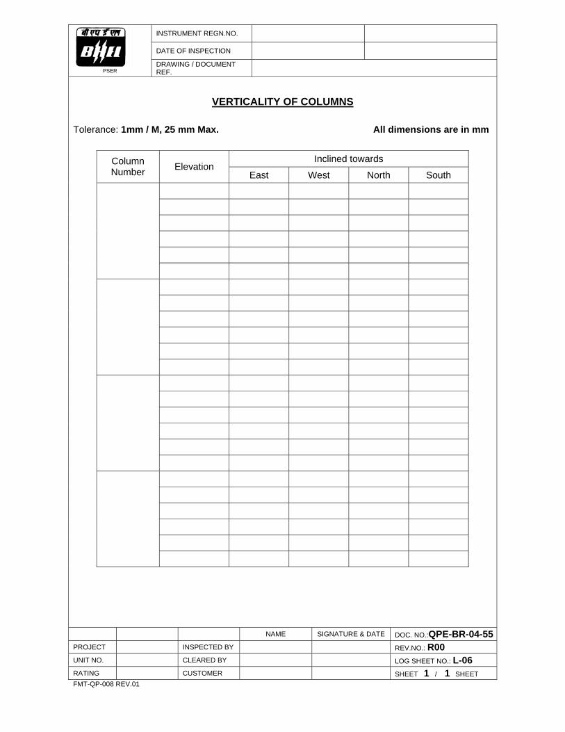
PSER
DRAWING / DOCUMENT REF.
VERTICALITY OF COLUMNS
Tolerance: 1mm / M, 25 mm Max. All dimensions are in mm
Inclined towards
Column Number Elevation
East West North South
NAME SIGNATURE & DATE DOC. NO.:QPE-BR-04-55PROJECT INSPECTED BY REV.NO.: R00
UNIT NO. CLEARED BY LOG SHEET NO.: L-06
RATING CUSTOMER SHEET 1 / 1 SHEET FMT-QP-008 REV.01
INSTRUMENT REGN.NO.
DATE OF INSPECTION
PSER
DRAWING / DOCUMENT REF.
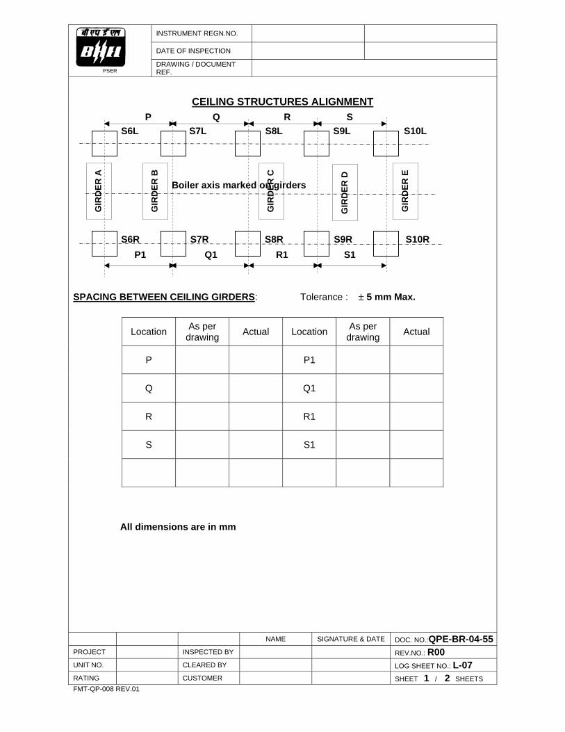
CEILING STRUCTURES ALIGNMENT
P Q R S S6L S7L S8L S9L S10L Boiler axis marked on girders S6R S7R S8R S9R S10R P1 Q1 R1 S1 SPACING BETWEEN CEILING GIRDERS: Tolerance : ± 5 mm Max.
Location As per drawing Actual Location As per
drawing Actual
P P1
Q Q1
R R1
S S1
All dimensions are in mm NAME SIGNATURE & DATE DOC. NO.:QPE-BR-04-55PROJECT INSPECTED BY REV.NO.: R00
UNIT NO. CLEARED BY LOG SHEET NO.: L-07
RATING CUSTOMER SHEET 1 / 2 SHEETS FMT-QP-008 REV.01
GIR
DER
A
GIR
DER
B
GIR
DER
C
GIR
DER
E
GIR
DER
D

INSTRUMENT REGN.NO.
DATE OF INSPECTION
PSER
DRAWING / DOCUMENT REF.
CEILING STRUCTURES ALIGNMENT
DIAGONAL DIFFERENCE BETWEEN ADJACENT CEILING GIRDERS
Tolerance : 25 mm Max.
Between Girders D1 D2 D1~D2
A & B
B & C
C & D
D & E
CEILING GIRDER C. L. VARIATION W.R.T. BOILER AXIS : Tolerance : 12 mm Max. All dimensions are in mm
Variation w.r.t. boiler axis
Girder Designation Towards Left Towards Right
Girder – A
Girder – B
Girder – C
Girder – D
Girder – E
NAME SIGNATURE & DATE DOC. NO.:QPE-BR-04-55PROJECT INSPECTED BY REV.NO.: R00
UNIT NO. CLEARED BY LOG SHEET NO.: L-07
RATING CUSTOMER SHEET 2 / 2 SHEETS FMT-QP-008 REV.01
INSTRUMENT REGN.NO.
DATE OF INSPECTION
PSER
DRAWING / DOCUMENT REF.
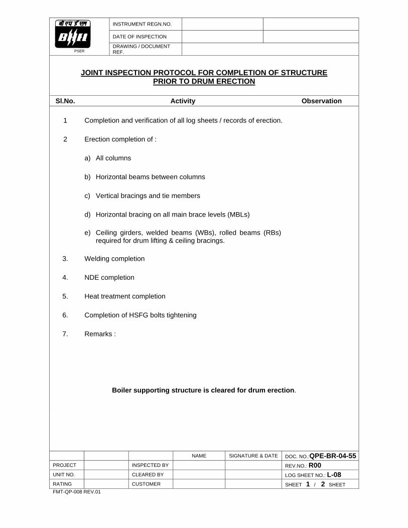
JOINT INSPECTION PROTOCOL FOR COMPLETION OF STRUCTURE
PRIOR TO DRUM ERECTION Sl.No. Activity Observation
1 Completion and verification of all log sheets / records of erection.
2 Erection completion of : a) All columns b) Horizontal beams between columns c) Vertical bracings and tie members d) Horizontal bracing on all main brace levels (MBLs)
e) Ceiling girders, welded beams (WBs), rolled beams (RBs) required for drum lifting & ceiling bracings.
3. Welding completion
4. NDE completion
5. Heat treatment completion
6. Completion of HSFG bolts tightening
7. Remarks :
Boiler supporting structure is cleared for drum erection. NAME SIGNATURE & DATE DOC. NO.:QPE-BR-04-55PROJECT INSPECTED BY REV.NO.: R00
UNIT NO. CLEARED BY LOG SHEET NO.: L-08
RATING CUSTOMER SHEET 1 / 2 SHEET FMT-QP-008 REV.01
INSTRUMENT REGN.NO.
DATE OF INSPECTION
PSER
DRAWING / DOCUMENT REF.
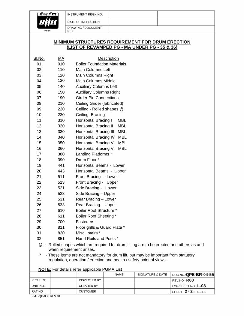
MINIMUM STRUCTURES REQUIREMENT FOR DRUM ERECTION
(LIST OF REVAMPED PG - MA UNDER PG - 35 & 36) Sl.No. MA Description
01 010 Boiler Foundation Materials 02 110 Main Columns Left 03 120 Main Columns Right 04 130 Main Columns Middle 05 140 Auxiliary Columns Left 06 150 Auxiliary Columns Right 07 190 Girder Pin Connections 08 210 Ceiling Girder (fabricated) 09 220 Ceiling - Rolled shapes @ 10 230 Ceiling Bracing 11 310 Horizontal Bracing I MBL 12 320 Horizontal Bracing II MBL 13 330 Horizontal Bracing III MBL 14 340 Horizontal Bracing IV MBL 15 350 Horizontal Bracing V MBL 16 360 Horizontal Bracing VI MBL 17 380 Landing Platforms * 18 390 Drum Floor * 19 441 Horizontal Beams - Lower 20 443 Horizontal Beams - Upper 21 511 Front Bracing - Lower 22 513 Front Bracing - Upper 23 521 Side Bracing - Lower 24 523 Side Bracing – Upper 25 531 Rear Bracing – Lower 26 533 Rear Bracing – Upper 27 610 Boiler Roof Structure * 28 611 Boiler Roof Sheeting * 29 700 Fasteners 30 811 Floor grills & Guard Plate * 31 820 Misc. stairs * 32 851 Hand Rails and Posts * @ - Rolled shapes which are required for drum lifting are to be erected and others as and when requirement arises. * - These items are not mandatory for drum lift, but may be important from statutory regulation, operation / erection and health / safety point of views. NOTE: For details refer applicable PGMA List
NAME SIGNATURE & DATE DOC.NO.:QPE-BR-04-55PROJECT INSPECTED BY REV.NO.: R00
UNIT NO. CLEARED BY LOG SHEET NO.: L-08
RATING CUSTOMER SHEET 2 / 2 SHEETS FMT-QP-008 REV.01

PSER
FEEDBACK ON QUALITY PLAN FOR INSTALLATION
In the Quality Plan for Installation (QPI), following Checks / Log sheets may be added / rewritten / deleted (cannot be carried out / not required) due to reasons as mentioned below :
Sheet No.
Of QPI Check No. /
Log Sheet No. Proposed Change / Reasons / Remarks
PROJECT DOC.NO. QPE-BR-04-55
UNIT NO. REV. NO. R00
RATING
From : To Head (Quality) , BHEL , PSER DJ – 9/1, Sector II, Salt Lake, Kolkata – 700 091
SHEET 1 / 1 SHEET
QUALITY PLAN FOR INSTALLATION
CIVIL WORKS (ERECTION)
MEJIA TPS EXTN. (UNITS 5 & 6) (2 x 250 MW)
BHARAT HEAVY ELECTRICALS LIMITED
POWER SECTOR EASTERN REGION DOC. NO. QPE-CL-04-51 REV. NO. R00 FMT-QP-001 REV.01

QUALITY PLAN FOR
INSTALLATION
CIVIL WORKS (ERECTION)
MEJIA TPS EXTN. (UNITS 5 & 6) ( 2 x 250 MW )
PREPARED BY
SR MANAGER/QLY, PSER APPROVED BY (HEAD / QLY, PSER
DOCUMENT NO. QPE - CL -04-51
ORIGINAL DATE OF ISSUE 20.08..2004 REVISION NO. & DATE R00 / 20.08.2004 COPY NO.
ISSUED TO
DATE OF ISSUE
CONTROLLED / INFORMATION COPY
ISSUED BY (SIGNATURE & DESIGNATION)
BHARAT HEAVY ELECTRICALS LIMITED POWER SECTOR EASTERN REGION

DOC. NO. : QPE-CL- 04-51
REV. NO. : R00
PSER
CONTENTS SHEET 1 / 1 SHEETS
S.NO.
DESCRIPTION
NO. OF SHEETS
1. STATUS OF AMENDMENTS 1
2. AUTHORISATION FOR DIFFERENT CATEGORIES OF CHECK 1
3. STATEMENT OF CHECKS FOR ERECTION i) Test Laboratory Establishment
ii) Bricks
iii) Earth Work
iv) Cement
v) Fine Aggregate (Sand)
vi) Course Aggregate
vii) Reinforcing Steel
viii) Water
ix) Form Work (Shuttering) x) Plant & Machinery
xi) Embedded Parts
xii) Concreting
xiii) Testing
xiv) Water Retaining Structure
xv) Water Supply
xvi) Drainage and Sanitation
xvii) Flooring and Finishing Works
xviii) Weathering Course
xix) Bitumen Top
xx) Plastering
xxi) Suspended Ceiling
xxii) Bought out Items
xxiii) Roof Decking
xxiv) Records
xxv) Wall Cladding Work
24
4. ANNEXURES (I TO VI ) 12
5. LOGSHEET L-00 TO L-05 6
6. DOCUMENTS REFFERED IN QUALITY PLAN 1 FMT-QP-003 REV.00

DOC. NO. : QPE-CL- 04-51 REV. NO. : R00
PSER
STATUS OF AMENDMENTS
SHEET 1 / 1 SHEETS
SL. NO.
REFERENCE OF SHEETS AMENDED
AMENDMENT NO. & DATE
REMARKS
- NIL -
FMT-QP-016 REV.00

PSER
AUTHORISATION FOR DIFFERENT CATEGORIES OF CHECK
FOR BHEL'S INTERNAL REFERENCE
Classification of checks
Symbol
Description
Inspection agency Clearing agency
A
Critical
Task performer &
surveillance by QAE (if available)
HOS
B
Major
Task performer
HOS
C
Minor
Task performer
Task performer
Legend :
HOS
Head of Section of BHEL
QAE Quality Assurance Engineer of BHEL
Note :
• Quantum of check shall be 100% for all characteristics unless otherwise
mentioned in reference documents. • QAE is also authorised to carry out surveillance in any of the “B” and “C”
category of checks at his discretion. • In case of non-conformity, before accepting , clearing agency shall
ensure dispositioning and the same shall be reflected in Logsheets/protocols.
FMT-QP-004 REV.01

PSER
AUTHORISATION FOR DIFFERENT CATEGORIES OF CHECK
Classification of checks
Checking Authority
Accepting Authority
Symbol Description
A
Critical
Customer &
BHEL
Customer &
BHEL
B Major Customer &
BHEL
Customer &
BHEL
C
Minor
BHEL
BHEL
Legend Customer :
M/S DVC
Note :
• Quantum of check shall be 100% for all characteristics unless otherwise
mentioned in reference documents. • DVC shall witness "A" category checks. He is also authorised to carry out
surveillance in any of the "B" and "C" category of checks at his discretion. • In case of non-conformity BHEL shall ensure dispositioning before
accepting and the same shall be reflected in Logsheets/protocols.
FMT-QP-004 REV.00

DOC. NO. : QPE-CL- 04-51 REV. NO. : R00
PSER
STATEMENT OF CHECKS
SHEET 1 / 24 SHEETS
Capacity / Type :
2 X 250 MW
System :
Civil
Sub-system :
------------------------
Area :
Erection
NOTES :
1. For checks where logsheets are not called for, suitable records should be maintained in the form of logsheets / protocols.
2. As an evidence of having carried out the work satisfactorily, a general purpose
logsheet, L-00 shall be maintained for all the checks. 3. Drawing / Contract requirements shall apply over and above the checks given.
4. Abbreviations used in the column ‘Type of check’ are:
R : Record verification M: Measurement V : Visual P : Physical
T : Test
FMT-QP-005 REV.00


DOC. NO. QPX - CL – 04-51
PSER
STATEMENT OF CHECKS REV.NO. R 00
SYSTEM : CIVIL WORKS
SUB-SYSTEM : TEST EQUIPMENT
AREA : ERECTION
SHEET 2 / 24 SHEETS
S.NO.
CHARACTERSTICS
TYPE OF CHECK
INSTRUMENT
CLASS
REFERENCE DOCUMENT
QUANTUM / FREQUENCY
OF CHECK
FORMAT OF
RECORD
REMARKS
1.0
Test Laboratory Establishment : Ensure that test laboratory is established at site sufficiently before commencement of civil work. (List of equipment as per Annexure-I)
V
B
Annexure-I
100%
FMT-QP-006 REV.00
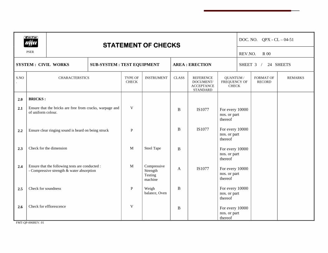
DOC. NO. QPX - CL – 04-51
PSER
STATEMENT OF CHECKS REV.NO. R 00
SYSTEM : CIVIL WORKS
SUB-SYSTEM : TEST EQUIPMENT
AREA : ERECTION
SHEET 3 / 24 SHEETS
S.NO.
CHARACTERSTICS
TYPE OF CHECK
INSTRUMENT
CLASS
REFERENCE DOCUMENT/
ACCEPTANCE STANDARD
QUANTUM /
FREQUENCY OF CHECK
FORMAT OF
RECORD
REMARKS
2.0
2.1
2.2
2.3
2.4
2.5
2.6
BRICKS : Ensure that the bricks are free from cracks, warpage and of uniform colour. Ensure clear ringing sound is heard on being struck Check for the dimension Ensure that the following tests are conducted : - Compressive strength & water absorption Check for soundness Check for efflorescence
V
P
M
M
P
V
Steel Tape Compressive Strength Testing machine Weigh balance, Oven
B
B
B
A
B
B
IS1077
IS1077
IS1077
For every 10000 nos. or part thereof For every 10000 nos. or part thereof For every 10000 nos. or part thereof For every 10000 nos. or part thereof For every 10000 nos. or part thereof For every 10000 nos. or part thereof
FMT-QP-006REV. 01
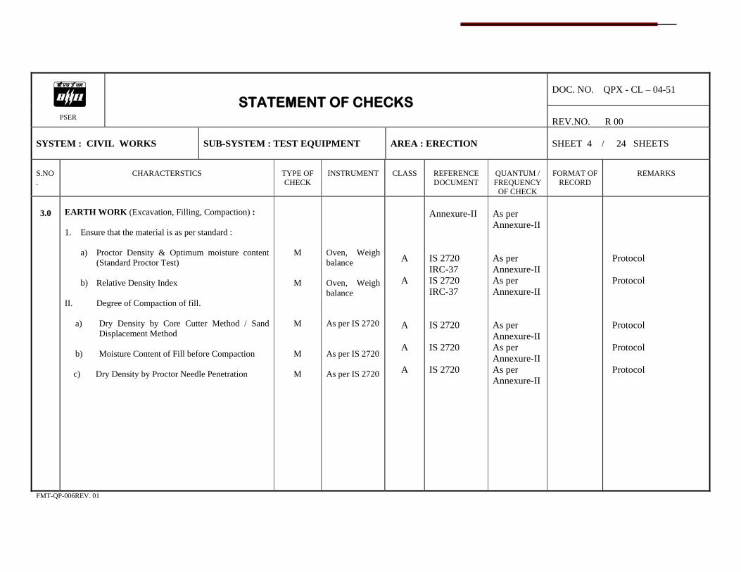
DOC. NO. QPX - CL – 04-51
PSER
STATEMENT OF CHECKS REV.NO. R 00
SYSTEM : CIVIL WORKS
SUB-SYSTEM : TEST EQUIPMENT
AREA : ERECTION
SHEET 4 / 24 SHEETS
S.NO.
CHARACTERSTICS
TYPE OF CHECK
INSTRUMENT
CLASS
REFERENCE DOCUMENT
QUANTUM / FREQUENCY
OF CHECK
FORMAT OF
RECORD
REMARKS
3.0
EARTH WORK (Excavation, Filling, Compaction) : 1. Ensure that the material is as per standard :
a) Proctor Density & Optimum moisture content (Standard Proctor Test)
b) Relative Density Index
II. Degree of Compaction of fill.
a) Dry Density by Core Cutter Method / Sand Displacement Method
b) Moisture Content of Fill before Compaction
c) Dry Density by Proctor Needle Penetration
M
M
M
M
M
Oven, Weigh balance Oven, Weigh balance As per IS 2720 As per IS 2720 As per IS 2720
A
A
A
A
A
Annexure-II IS 2720 IRC-37 IS 2720 IRC-37 IS 2720 IS 2720 IS 2720
As per Annexure-II As per Annexure-II As per Annexure-II As per Annexure-II As per Annexure-II As per Annexure-II
Protocol Protocol Protocol Protocol Protocol
FMT-QP-006REV. 01
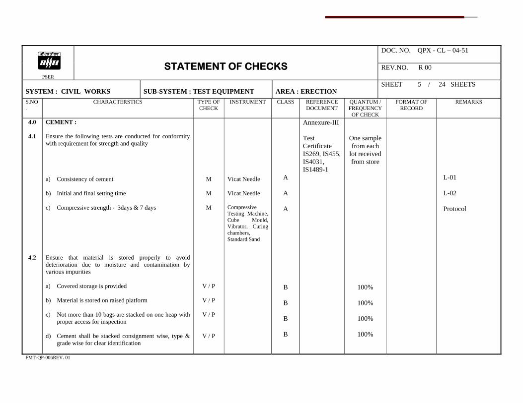
DOC. NO. QPX - CL – 04-51
PSER
STATEMENT OF CHECKS REV.NO. R 00
SYSTEM : CIVIL WORKS
SUB-SYSTEM : TEST EQUIPMENT
AREA : ERECTION
SHEET 5 / 24 SHEETS
S.NO.
CHARACTERSTICS TYPE OF CHECK
INSTRUMENT CLASS REFERENCE DOCUMENT
QUANTUM / FREQUENCY
OF CHECK
FORMAT OF RECORD
REMARKS
4.0
4.1
4.2
CEMENT : Ensure the following tests are conducted for conformity with requirement for strength and quality a) Consistency of cement b) Initial and final setting time c) Compressive strength - 3days & 7 days Ensure that material is stored properly to avoid deterioration due to moisture and contamination by various impurities a) Covered storage is provided b) Material is stored on raised platform c) Not more than 10 bags are stacked on one heap with
proper access for inspection d) Cement shall be stacked consignment wise, type &
grade wise for clear identification
M
M
M
V / P
V / P
V / P
V / P
Vicat Needle Vicat Needle Compressive Testing Machine, Cube Mould, Vibrator, Curing chambers, Standard Sand
A
A
A
B
B
B
B
Annexure-III Test Certificate IS269, IS455, IS4031, IS1489-1
One sample from each
lot received from store
100%
100%
100%
100%
L-01 L-02 Protocol
FMT-QP-006REV. 01

DOC. NO. QPX-CL- 04-51
PSER
STATEMENT OF CHECKS REV.NO. R 00
SYSTEM : CIVIL WORKS
SUB-SYSTEM : TEST EQUIPMENT
AREA : ERECTION
SHEET 6 / 24 SHEETS
S.NO.
CHARACTERSTICS
TYPE OF CHECK
INSTRUMENT
CLASS
REFERENCE DOCUMENT
QUANTUM /
FREQUENCY OF CHECK
FORMAT OF
RECORD
REMARKS
5.0
5.1
5.2
FINE AGGREGATE (SAND) : Ensure that the following tests are conducted for each source of supply and check the material is as per standards (for mix design) a) Silt & Clay content
b) Sieve analysis (Particle size and shape)
c) Bulking of sand
d) Specific gravity, density, voids & absorption
e) Moisture content
f) Dleterious materials
g) Petrographic examination
h) Soundness
i) Reaction with Alkali : Mortar making properties.
Conduct tests and ensure that the material is as per standards before use at site a) Silt & Clay content b) Sieve analysis c) Bulking of sand
M
M
Measuring jar Weigh balance Sieve set, oven Oven Sieve set Weigh balance
B
B
Annexure-III Test certificate IS383, IS515, IS2386 Test certificate IS383, IS515, IS2386
As per Annexure- III
As per Annexure-III
Protocol
Protocol
L-03
FMT-QP-006REV. 01

DOC. NO. QPX-CL-04-51
PSER
STATEMENT OF CHECKS REV.NO. R 00
SYSTEM : CIVIL WORKS
SUB-SYSTEM : TEST EQUIPMENT
AREA : ERECTION
SHEET 7 / 24 SHEETS
S.NO.
CHARACTERSTICS
TYPE OF CHECK
INSTRUMENT
CLASS
REFERENCE DOCUMENT
QUANTUM /
FREQUENCY OF CHECK
FORMAT OF
RECORD
REMARKS
6.0
6.1
COARSE AGGREGATE : (Stone metal / Gravel) Conduct the following tests and ensure that the material is as per standards (for Mix design) a) Sieve Analysis (Particle Size and Shape)
b) Moisture content
c) Specofoc gravity
d) Crushing Strength
e) Bulk density
f) Absorption value, Abration value & Impact Value
g) Voids
h) Soundness
i) Reaction with Alkali
j) Petrographic examination
k) Deleterious materials
l) Temperature Cycle test
m) Flakiness
M
M
M
M
M
M
M / V
Lab Test
Lab Test
V / P
Lab Test
Lab Test
Lab Test
Sieve set weigh balance, Oven, Jar & necessary chemicals
B
Annexure-III Test certificate, IS383, IS515, IS2386
As per Annexure-III
Protocol
L-04
FMT-QP-006REV. 01
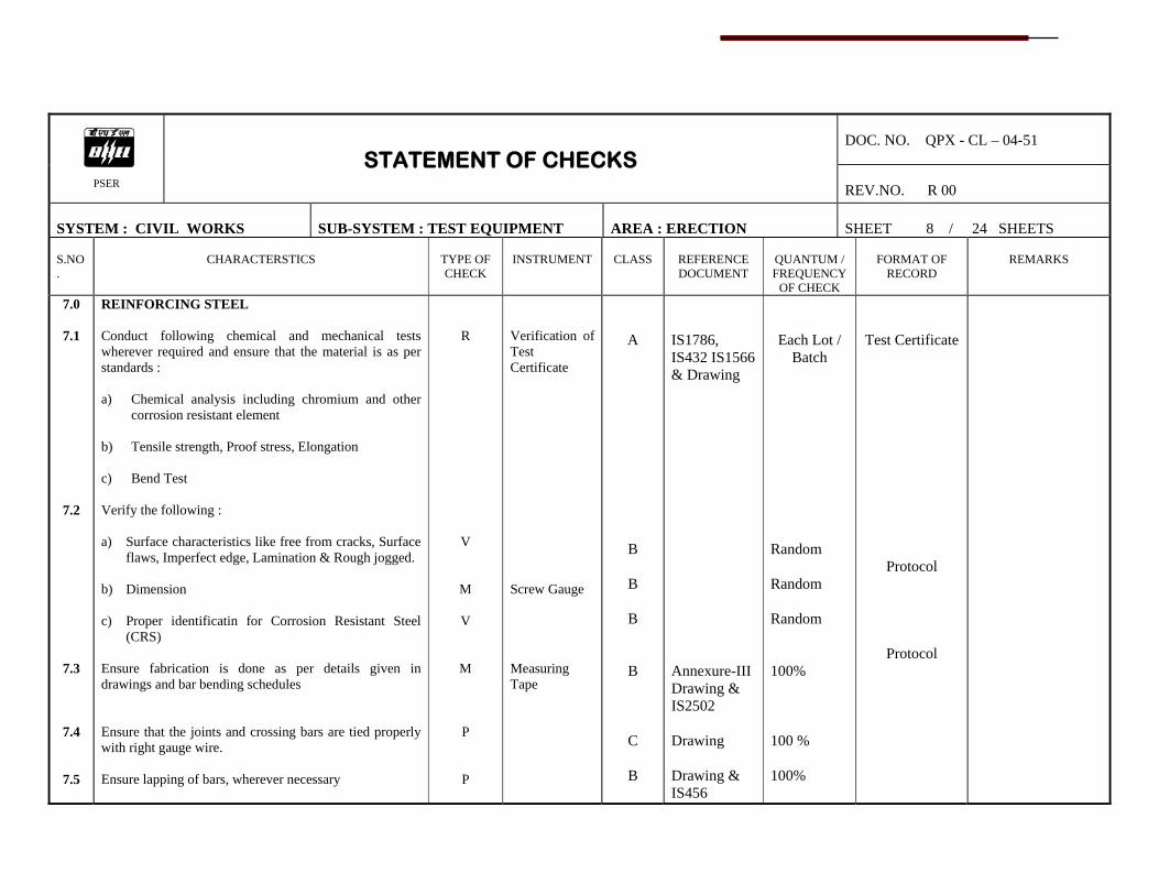
DOC. NO. QPX - CL – 04-51
PSER
STATEMENT OF CHECKS REV.NO. R 00
SYSTEM : CIVIL WORKS
SUB-SYSTEM : TEST EQUIPMENT
AREA : ERECTION
SHEET 8 / 24 SHEETS
S.NO.
CHARACTERSTICS
TYPE OF CHECK
INSTRUMENT
CLASS
REFERENCE DOCUMENT
QUANTUM / FREQUENCY
OF CHECK
FORMAT OF
RECORD
REMARKS
7.0
7.1
7.2
7.3
7.4
7.5
REINFORCING STEEL Conduct following chemical and mechanical tests wherever required and ensure that the material is as per standards : a) Chemical analysis including chromium and other
corrosion resistant element b) Tensile strength, Proof stress, Elongation c) Bend Test Verify the following : a) Surface characteristics like free from cracks, Surface
flaws, Imperfect edge, Lamination & Rough jogged. b) Dimension c) Proper identificatin for Corrosion Resistant Steel
(CRS) Ensure fabrication is done as per details given in drawings and bar bending schedules Ensure that the joints and crossing bars are tied properly with right gauge wire. Ensure lapping of bars, wherever necessary
R
V
M
V
M
P
P
Verification of Test Certificate Screw Gauge Measuring Tape
A
B
B
B
B
C
B
IS1786, IS432 IS1566 & Drawing Annexure-III Drawing & IS2502 Drawing Drawing & IS456
Each Lot / Batch
Random Random Random 100% 100 % 100%
Test Certificate
Protocol
Protocol
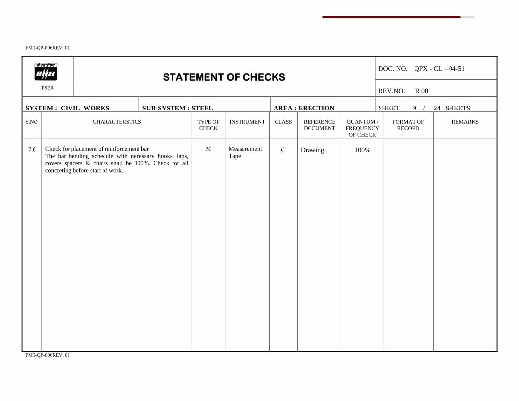
FMT-QP-006REV. 01
DOC. NO. QPX - CL – 04-51
PSER
STATEMENT OF CHECKS REV.NO. R 00
SYSTEM : CIVIL WORKS
SUB-SYSTEM : STEEL
AREA : ERECTION
SHEET 9 / 24 SHEETS
S.NO.
CHARACTERSTICS
TYPE OF CHECK
INSTRUMENT
CLASS
REFERENCE DOCUMENT
QUANTUM / FREQUENCY
OF CHECK
FORMAT OF
RECORD
REMARKS
7.6
Check for placement of reinforcement bar The bar bending schedule with necessary hooks, laps, covers spacers & chairs shall be 100%. Check for all concreting before start of work.
M
Measurement Tape
C
Drawing
100%
FMT-QP-006REV. 01

DOC. NO. QPX - CL – 04-51
PSER
STATEMENT OF CHECKS REV.NO. R 00
SYSTEM : CIVIL WORKS
SUB-SYSTEM : WATER
AREA : ERECTION
SHEET 10 / 24 SHEETS
S.NO.
CHARACTERSTICS
TYPE OF CHECK
INSTRUMENT
CLASS
REFERENCE DOCUMENT
QUANTUM / FREQUENCY
OF CHECK
FORMAT OF
RECORD
REMARKS
8.0
8.1
8.2
8.3
8.4
WATER : (Customer Input) Ensure that water from all source is potable as per the standard before use Conduct test for neutralisation of water Check and ascertain limits of solids Conduct test for PH value
Testing
M
M
M
Indicator Lab Test PH Meter
B
B
B
B
Annexure-III, Test certificate Annexure-III, IS 3025 & IS456 Annexure-III, IS 3025 & IS456 Annexure-III, IS456
Once a month per
source
Once a month per
source
Once a month per
source
Once a month per
source
Site logbook
Site logbook
Site logbook
FMT-QP-006REV. 01

DOC. NO. QPX - CL – 04-51
PSER
STATEMENT OF CHECKS REV.NO. R 00
SYSTEM : CIVIL WORKS
SUB-SYSTEM : BRICKS
AREA : ERECTION
SHEET 11 / 24 SHEETS
S.NO.
CHARACTERSTICS
TYPE OF CHECK
INSTRUMENT
CLASS
REFERENCE DOCUMENT
QUANTUM / FREQUENCY
OF CHECK
FORMAT OF
RECORD
REMARKS
9.0
9.1
9.2
FORM WORK (SHUTTERING) : Ensure the form work is as per contract specifications and drawings Check for the following : a) Cleanliness, Damage and warpage b) Ensure internal dimension of box forms and
distances between internal surfaces of shuttering of walls.
c) Ensure horizontality before and after placement of
reinforcement d) Staging e) Ensure the following : (i) Soundness of material (ii) Proper joining bracing (iii) Proper support (iv) Verticality of side shuttering before and after
reinforcement
P / V
V
M
M
R /V /P
M/ V
V
V
M
Measuring Tape
Spirit Level, plumb bob
Hammer
Plumb bob
B
B
B
B
B
C
C
C
C
Annexure-III Drawing Drawing Drawing/ Design Drawing Drawing Drawing Drawing
100%
100%
100%
100%
100%
100%
100%
100%
100%
FMT-QP-006REV. 01
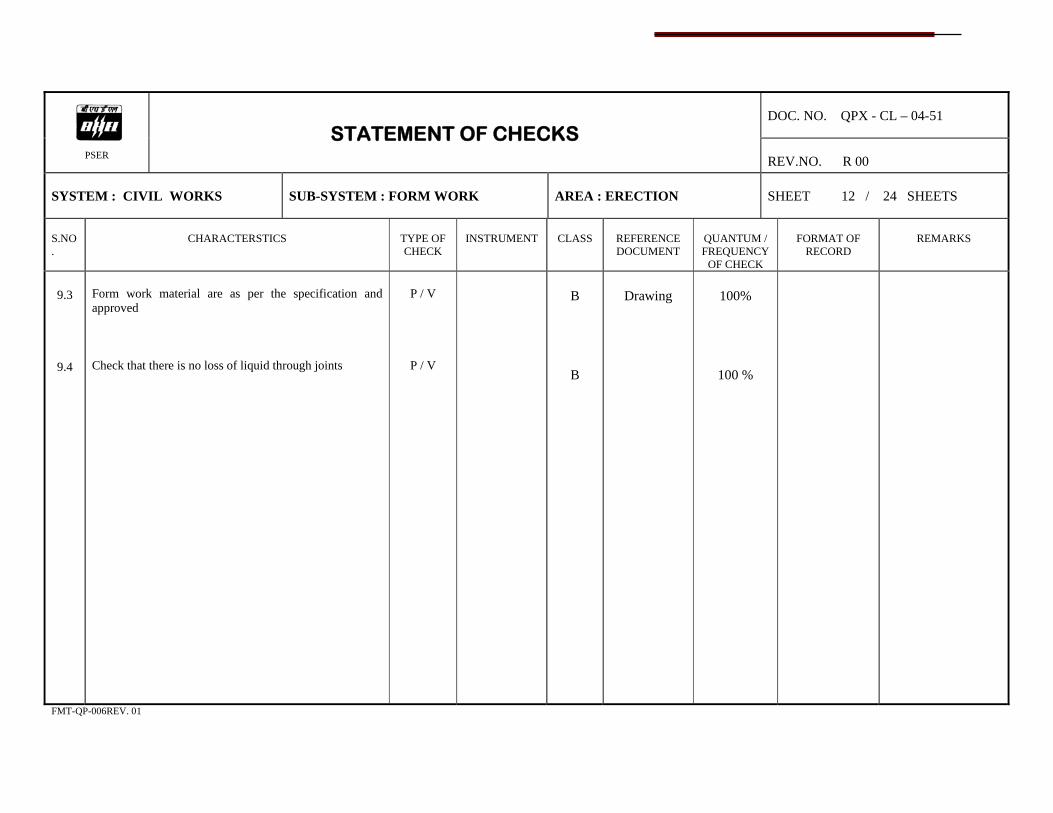
DOC. NO. QPX - CL – 04-51
PSER
STATEMENT OF CHECKS REV.NO. R 00
SYSTEM : CIVIL WORKS
SUB-SYSTEM : FORM WORK
AREA : ERECTION
SHEET 12 / 24 SHEETS
S.NO.
CHARACTERSTICS
TYPE OF CHECK
INSTRUMENT
CLASS
REFERENCE DOCUMENT
QUANTUM / FREQUENCY
OF CHECK
FORMAT OF
RECORD
REMARKS
9.3
9.4
Form work material are as per the specification and approved Check that there is no loss of liquid through joints
P / V
P / V
B
B
Drawing
100%
100 %
FMT-QP-006REV. 01

DOC. NO. QPX - CL – 04-51
PSER
STATEMENT OF CHECKS REV.NO. R 00
SYSTEM : CIVIL WORKS
SUB-SYSTEM : PLANT & MACHINERY
AREA : ERECTION
SHEET 13 / 24 SHEETS
S.NO.
CHARACTERSTICS
TYPE OF CHECK
INSTRUMENT
CLASS
REFERENCE DOCUMENT
QUANTUM / FREQUENCY
OF CHECK
FORMAT OF
RECORD
REMARKS
10.0
10.1
PLANT & MACHINERY : Ensure availability of the following : a) Concrete Mixer b) Vibrators of adequate capacity c) Weigh batches & batching plant d) Lighting e) Air compressor f) Pumps g) Jack hammer (if required) h) Transit mixer i) Generator j) Winches k) Cranes l) Escavator, Power roller, plate compactor
V / P
A
100%
FMT-QP-006REV. 01
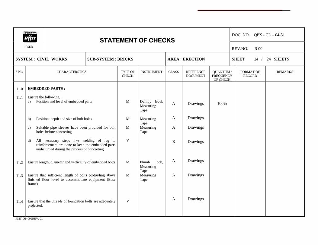
DOC. NO. QPX - CL – 04-51
PSER
STATEMENT OF CHECKS REV.NO. R 00
SYSTEM : CIVIL WORKS
SUB-SYSTEM : BRICKS
AREA : ERECTION
SHEET 14 / 24 SHEETS
S.NO.
CHARACTERSTICS
TYPE OF CHECK
INSTRUMENT
CLASS
REFERENCE DOCUMENT
QUANTUM / FREQUENCY
OF CHECK
FORMAT OF
RECORD
REMARKS
11.0
11.1
11.2
11.3
11.4
EMBEDDED PARTS : Ensure the following : a) Position and level of embedded parts b) Position, depth and size of bolt holes c) Suitable pipe sleeves have been provided for bolt
holes before concreting d) All necessary steps like welding of lug to
reinforcement are done to keep the embedded parts undisturbed during the process of concreting
Ensure length, diameter and verticality of embedded bolts Ensure that sufficient length of bolts protruding above finished floor level to accommodate equipment (Base frame) Ensure that the threads of foundation bolts are adequately projected.
M
M
M
V
M
M
V
Dumpy level, Measuring Tape Measuring Tape Measuring Tape Plumb bob, Measuring Tape Measuring Tape
A
A
A
B
A
A
A
Drawings
Drawings
Drawings
Drawings
Drawings
Drawings
Drawings
100%
FMT-QP-006REV. 01
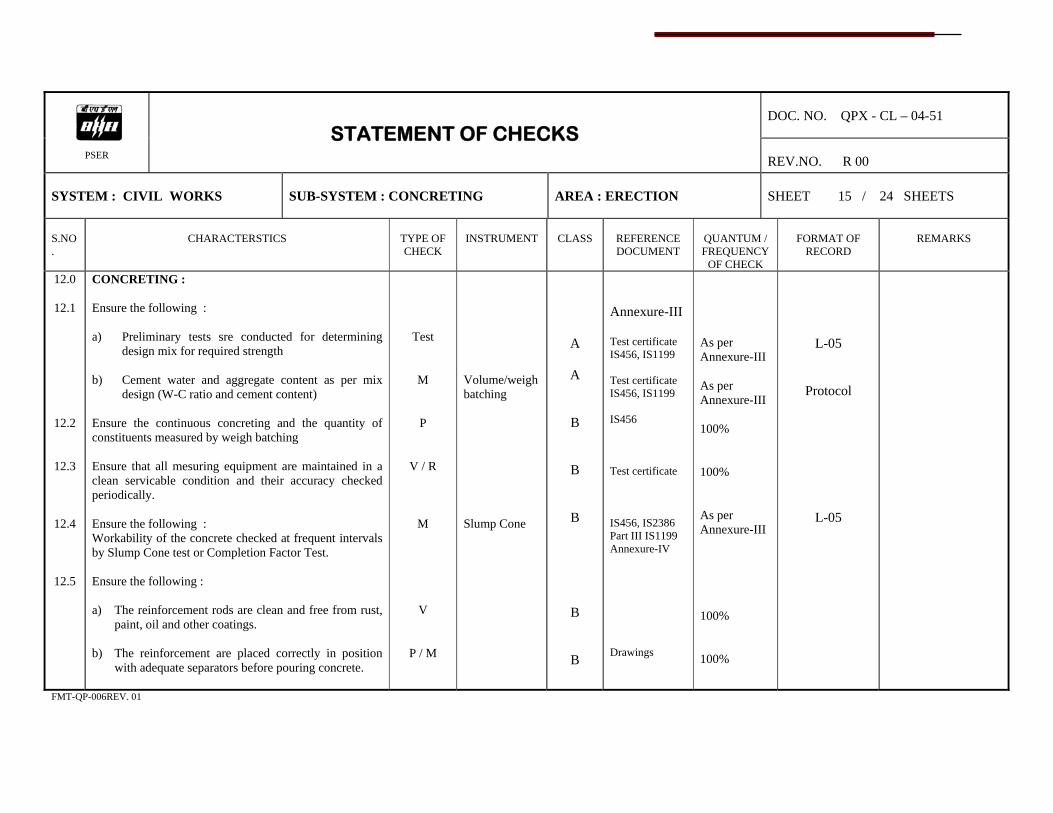
DOC. NO. QPX - CL – 04-51
PSER
STATEMENT OF CHECKS REV.NO. R 00
SYSTEM : CIVIL WORKS
SUB-SYSTEM : CONCRETING
AREA : ERECTION
SHEET 15 / 24 SHEETS
S.NO.
CHARACTERSTICS
TYPE OF CHECK
INSTRUMENT
CLASS
REFERENCE DOCUMENT
QUANTUM / FREQUENCY
OF CHECK
FORMAT OF
RECORD
REMARKS
12.0
12.1
12.2
12.3
12.4
12.5
CONCRETING : Ensure the following : a) Preliminary tests sre conducted for determining
design mix for required strength b) Cement water and aggregate content as per mix
design (W-C ratio and cement content) Ensure the continuous concreting and the quantity of constituents measured by weigh batching Ensure that all mesuring equipment are maintained in a clean servicable condition and their accuracy checked periodically. Ensure the following : Workability of the concrete checked at frequent intervals by Slump Cone test or Completion Factor Test. Ensure the following : a) The reinforcement rods are clean and free from rust,
paint, oil and other coatings. b) The reinforcement are placed correctly in position
with adequate separators before pouring concrete.
Test
M
P
V / R
M
V
P / M
Volume/weigh batching Slump Cone
A
A
B
B
B
B
B
Annexure-III Test certificate IS456, IS1199 Test certificate IS456, IS1199 IS456 Test certificate IS456, IS2386 Part III IS1199 Annexure-IV Drawings
As per Annexure-III As per Annexure-III 100% 100% As per Annexure-III 100% 100%
L-05
Protocol
L-05
FMT-QP-006REV. 01

DOC. NO. QPX - CL – 04-51
PSER
STATEMENT OF CHECKS REV.NO. R 00
SYSTEM : CIVIL WORKS
SUB-SYSTEM : CONCRETING
AREA : ERECTION
SHEET 16 / 24 SHEETS
S.NO.
CHARACTERSTICS
TYPE OF CHECK
INSTRUMENT
CLASS
REFERENCE DOCUMENT
QUANTUM / FREQUENCY
OF CHECK
FORMAT OF
RECORD
REMARKS
12.6
Check and ensure the following : a) Area to be concreted is clean and free from debris
and any extraneous matter of water logging b) Water stopper or seals are introduced wherever
required c) Old concrete surfaces are chopped, cleande with wire
brush, wetted and coat of cement slurry applied before layingnew concrete
d) The temperature of concrete does not exceed 25° C
for major equipment foundation, use ice proportionally to maintain temperature
e) Stripping time of formwork is strictly regulated as
follows in normal circumstances (where temperature is above 20° C) and where ordinary cement is used.
i) Wall columns & vertical sides of beams : 24 to 48 hours ii) Slab (props left under) : 3 days iii) Beams soffits (props left under) : 7 days iv) Removal of props to slabs span less than 4.5m : 7 days v) Removal of props to slabs spanning over 4.5m : 14 days vi) Removal of props to beams and arches : 14 days Spanning upto 6 m
V
P
P
M
M / P
Thermometer Thermometer
B
B
A
B
B
Drawing IS456 IS456
100%
100%
100%
100%
100%
FMT-QP-006REV. 01
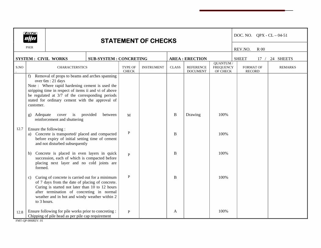
DOC. NO. QPX - CL – 04-51
PSER
STATEMENT OF CHECKS REV.NO. R 00
SYSTEM : CIVIL WORKS
SUB-SYSTEM : CONCRETING
AREA : ERECTION
SHEET 17 / 24 SHEETS
S.NO.
CHARACTERSTICS
TYPE OF CHECK
INSTRUMENT
CLASS
REFERENCE DOCUMENT
QUANTUM / FREQUENCY
OF CHECK
FORMAT OF
RECORD
REMARKS
12.7
12.8
f) Removal of props to beams and arches spanning over 6m : 21 days
Note : Where rapid hardening cement is used the stripping time in respect of items ii and vi of above be regulated at 3/7 of the corresponding periods stated for ordinary cement with the approval of customer. g) Adequate cover is provided between
reinforcement and shuttering Ensure the following : a) Concrete is transported/ placed and compacted
before expiry of initial setting time of cement and not disturbed subsequently
b) Concrete is placed in even layers in quick
succession, each of which is compacted before placing next layer and no cold joints are formed.
c) Curing of concrete is carried out for a minimum
of 7 days from the date of placing of concrete. Curing is started not later than 10 to 12 hours after termination of concreting in normal weather and in hot and windy weather within 2 to 3 hours.
Ensure following for pile works prior to concreting : Chipping of pile head as per pile cap requirement
M
P
P
P
P
B
B
B
B
A
Drawing
100%
100%
100%
100%
100%
FMT-QP-006REV. 01
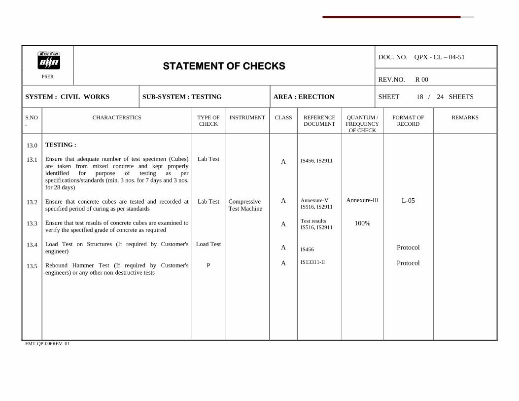
DOC. NO. QPX - CL – 04-51
PSER
STATEMENT OF CHECKS REV.NO. R 00
SYSTEM : CIVIL WORKS
SUB-SYSTEM : TESTING
AREA : ERECTION
SHEET 18 / 24 SHEETS
S.NO.
CHARACTERSTICS
TYPE OF CHECK
INSTRUMENT
CLASS
REFERENCE DOCUMENT
QUANTUM / FREQUENCY
OF CHECK
FORMAT OF
RECORD
REMARKS
13.0
13.1
13.2
13.3
13.4
13.5
TESTING : Ensure that adequate number of test specimen (Cubes) are taken from mixed concrete and kept properly identified for purpose of testing as per specifications/standards (min. 3 nos. for 7 days and 3 nos. for 28 days) Ensure that concrete cubes are tested and recorded at specified period of curing as per standards Ensure that test results of concrete cubes are examined to verify the specified grade of concrete as required Load Test on Structures (If required by Customer's engineer) Rebound Hammer Test (If required by Customer's engineers) or any other non-destructive tests
Lab Test
Lab Test
Load Test
P
Compressive Test Machine
A
A
A
A
A
IS456, IS2911 Annexure-V IS516, IS2911 Test results IS516, IS2911 IS456 IS13311-II
Annexure-III
100%
L-05
Protocol
Protocol
FMT-QP-006REV. 01
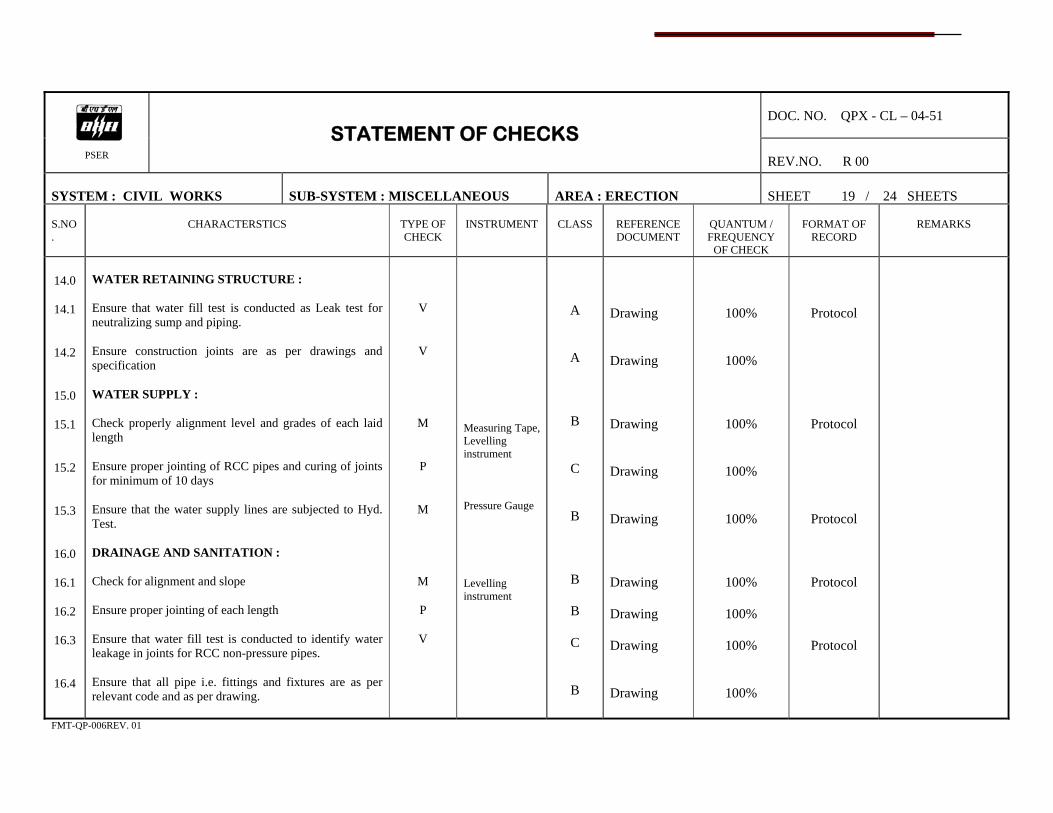
DOC. NO. QPX - CL – 04-51
PSER
STATEMENT OF CHECKS REV.NO. R 00
SYSTEM : CIVIL WORKS
SUB-SYSTEM : MISCELLANEOUS
AREA : ERECTION
SHEET 19 / 24 SHEETS
S.NO.
CHARACTERSTICS
TYPE OF CHECK
INSTRUMENT
CLASS
REFERENCE DOCUMENT
QUANTUM / FREQUENCY
OF CHECK
FORMAT OF
RECORD
REMARKS
14.0
14.1
14.2
15.0
15.1
15.2
15.3
16.0
16.1
16.2
16.3
16.4
WATER RETAINING STRUCTURE : Ensure that water fill test is conducted as Leak test for neutralizing sump and piping. Ensure construction joints are as per drawings and specification WATER SUPPLY : Check properly alignment level and grades of each laid length Ensure proper jointing of RCC pipes and curing of joints for minimum of 10 days Ensure that the water supply lines are subjected to Hyd. Test. DRAINAGE AND SANITATION : Check for alignment and slope Ensure proper jointing of each length Ensure that water fill test is conducted to identify water leakage in joints for RCC non-pressure pipes. Ensure that all pipe i.e. fittings and fixtures are as per relevant code and as per drawing.
V
V
M
P
M
M
P
V
Measuring Tape, Levelling instrument Pressure Gauge Levelling instrument
A
A
B
C
B
B
B
C
B
Drawing Drawing Drawing Drawing Drawing Drawing Drawing Drawing Drawing
100%
100%
100%
100%
100%
100%
100%
100%
100%
Protocol
Protocol
Protocol
Protocol
Protocol
FMT-QP-006REV. 01

DOC. NO. QPX - CL – 04-51
PSER
STATEMENT OF CHECKS REV.NO. R 00
SYSTEM : CIVIL WORKS
SUB-SYSTEM : MISCELLANEOUS
AREA : ERECTION
SHEET 20 / 24 SHEETS
S.NO.
CHARACTERSTICS
TYPE OF CHECK
INSTRUMENT
CLASS
REFERENCE DOCUMENT
QUANTUM / FREQUENCY
OF CHECK
FORMAT OF
RECORD
REMARKS
17.0
17.1
17.2
17.3
17.4
18.0
18.1
18.2
19.0
19.1
20.0
20.1
FLOORING AND FINISHING WORKS : Check for levels and slope Ensure that the floors are chipped prior to commencement of actual finishing work. Ensure that the cement concrete floors are cured minimum for 7 days Ensure that the tiled finished floors are polished as per the requirement of customer WEATHERING COURSE : Check for slope Check for joint finishing BITUMEN TOP : Chesk for proper laying of Bitumen top PLASTERING : Ensure that the plastering of brick walls shall be of min. 19 mm thick for outside and 13 mm for inside
M
V
V
V
M
V
V
V / M
Dumpy Level Dumpy Level Steel Tape
B
C
C
B
B
B
B
B
Drawing Drawing Drawing Drawing Drawing
100%
100%
100%
100%
100%
100%
100%
Random Test
Protocol
FMT-QP-006REV. 01

DOC. NO. QPX - CL – 04-51
PSER
STATEMENT OF CHECKS REV.NO. R 00
SYSTEM : CIVIL WORKS
SUB-SYSTEM : MISCELLANEOUS
AREA : ERECTION
SHEET 21 / 24 SHEETS
S.NO.
CHARACTERSTICS
TYPE OF CHECK
INSTRUMENT
CLASS
REFERENCE DOCUMENT
QUANTUM / FREQUENCY
OF CHECK
FORMAT OF
RECORD
REMARKS
20.2
20.3
21.0
21.1
21.2
21.3
22.0
22.1
23.0
Ensure that the plastering of concrete ceiling is as specified. Ensure that the curing of plastering surfaces are carried out for 7 days (min.) SUSPENDED CEILING : Ensure that the false ceing is done as per drawing / specification Ensure that as per requirement resin mineral wool is packed in black polythene and laid on top of Ceiling panels. Ensure density of resinbonded mineral wool BOUGHT OUT ITEMS : Check the bought out items are as per Technical specification / IS codes before use. Roof Decking : a) Sheets approved of samples by engineer in-charge. - Review of T/C - Dimension Check including thickness, depth of
valley centre to centre distance of valley
M
V
M / V
V
M
Verifi-cation
M
Steel Tape Steel Tape Measuring Tape
B
B
B
B
B
B
B
Drawing Drawing, IS8183 Drawing, IS8183 Annexure-VI Drawing
100%
100%
100%
100%
Sample Test
100%
Sample Test
Protocol
Protocol
FMT-QP-006REV. 01

DOC. NO. QPX - CL – 04-51
PSER
STATEMENT OF CHECKS REV.NO. R 00
SYSTEM : CIVIL WORKS
SUB-SYSTEM : MISCELLANEOUS
AREA : ERECTION
SHEET 22 / 24 SHEETS
S.NO.
CHARACTERSTICS
TYPE OF CHECK
INSTRUMENT
CLASS
REFERENCE DOCUMENT
QUANTUM / FREQUENCY
OF CHECK
FORMAT OF
RECORD
REMARKS
24.0
- Check phosphating on both sides as per IS 3618 class B - Check one coat of chlorinated rubber paints as per
Technical Specification. b) Fixing of Decking Seats Appearance, Water Tightness, Check side end laps, Check conformity of Fixing as per approved design, Review of T/C for fasteners and Z spacers RECORDS : Prepare logsheets / Protocols as per drawing and record the following : a) Orientation with co-ordinates b) Elevation / levels c) Slope d) Pitch / Diagonals e) Spacing / Diagonals
V
V
V
V / M
Steel Tape, Dumpy Level, Theodolite
B
B
B
A
IS 3618 Drawing
Sample Test
Sample Test
100%
100%
FMT-QP-006REV. 01

DOC. NO. QPX - CL – 04-51
PSER
STATEMENT OF CHECKS REV.NO. R 00
SYSTEM : CIVIL WORKS
SUB-SYSTEM : RECORDS
AREA : ERECTION
SHEET 23 / 24 SHEETS
S.NO.
CHARACTERSTICS
TYPE OF CHECK
INSTRUMENT
CLASS
REFERENCE DOCUMENT
QUANTUM / FREQUENCY
OF CHECK
FORMAT OF
RECORD
REMARKS
25.0
Wall Cladding Work : a) INNER SHEETS
i) Approval of sample by Engineer In-charge
ii) Review of TC for physical & chemical properties.
iii) Dimensional conformities including
thickness, Rib depth, cover width.
iv) Check for glaminizing weight of zinc coating
v) Type of permanently colour coating and
appearance b) OUTER SKIN SHEETS i) Approval of sample by Engineer In-charge
ii) Review of TC for physical & chemical properties
iii) Dimensional conformities including
thickness, Rib depth, cover width.
iv) Check for Fluor Polymer Paint Coating Thickness
R
M
M
V
V
R
M
M
Measuring Tape Weighing machine Measuring Tape Magnetic Gauge
B
B
Drawing / Specification Drawing / Specification
100%
100%
FMT-QP-006REV. 01

DOC. NO. QPX - CL – 04-51
PSER
STATEMENT OF CHECKS REV.NO. R 00
SYSTEM : CIVIL WORKS
SUB-SYSTEM : RECORDS
AREA : ERECTION
SHEET 24 / 24 SHEETS
S.NO.
CHARACTERSTICS
TYPE OF CHECK
INSTRUMENT
CLASS
REFERENCE DOCUMENT
QUANTUM / FREQUENCY
OF CHECK
FORMAT OF
RECORD
REMARKS
c) Thermal Insulation Thickness, Thermal conductivity at 50°C, Density and review of TC for all test as per IS 8183 i) Check positioning and location of laps.
ii) Check alignment of sheets and fixing (Plumb & level)
iii) Check End lap and Side lap fixing of other
item
iv) Check location and spacing of fixing.
M / V
M
M
V
V/ M
Measuring Tape Water level / Plumb Measuring Tape
B
B
100%
100%
FMT-QP-006REV. 01


Annexure - I DOC. NO. QPE-CL-04-51 REV.NO. R00 SHEET No. 1 of 2
RECOMMENDED LABORATORY EQUIPMENTS / MEASURING DEVICES / INSTRUMENTS FOR CIVIL WORKS
Sl. No. Broad Class Nomenclature Description Utility Test Procedure Code Ref. 1.1 Vicat Apparatus
Cement Consistency & Penetration
Penetration of Standard needle
IS 5513
1.2 Lechatelier's test Apparatus
Cement shrinkage
Size variation after curing of sample
IS 5514
1.3 Mould (cement) (70.7X70.7X70.7 mm)
Cement Cubes Cubes made of 1:3 cement Sand IS 10086
1.4 Cement Mortar Mould Vibrator
Cube Compaction
Vibration for fixed duration
IS 10078
1.5 Concrete cube mould (150X150X150)mm
Concrete Cubes IS 10086
1.6 Compressive strength Testing Machine
Concrete Cube Test Crushing strength of cube IS 2505
1.7 Concrete Slump cone
Workability check
Drop in cone height of concrete
IS 7320
1.8 Concrete aggregate sieves
Sieve analysis
Sieving
IS 383
1.9 Fine aggregate sieves
Sieve analysis
Sieving
IS 383
1.10 Shieve shaker
Mechanical shieving
1.
Routine Test Lab. Equipments
1.11 Aggregate impact Test Machine
Impact Value aggregate
IS 9377

Annexure - I DOC. NO. QPE-CL-04-51 REV.NO. R00 SHEET No. 2 of 2
RECOMMENDED LABORATORY EQUIPMENTS / MEASURING DEVICES / INSTRUMENTS FOR CIVIL WORKS
Sl. No. Broad Class Nomenclature Description Utility Test Procedure Code Ref. 2.1 Theodolite & levelling Staff
Levelling, centre line marking & Verticality measurement
Measurement & Recording
2.
Dimensional & Allied Measuring Equipment
2.2 Measuring Tape
Dimension
3.1 Oven
Material Drying for moisture for moisture control
Material to be kept for specific duration
3.2 Physical Balance
Weighing
3.3 P.H. Meter
Measuring PH value
IS 456, IS 2720
3.
Process Control accessories
3.4 Soil Compaction Testing Apparatus
Soil Compaction Testing


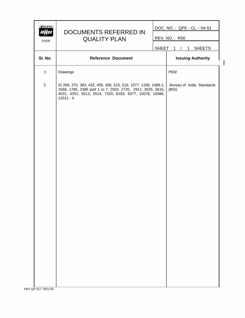
DOC. NO. : QPE - CL – 04-51 REV. NO. : R00
PSER
DOCUMENTS REFERRED IN QUALITY PLAN
SHEET 1 / 1 SHEETS
Sl. No.
Reference Document
Issuing Authority
1
2.
Drawings IS 269, 370, 383, 432, 455, 456, 515, 516, 1077, 1199, 1489-1, 1566, 1786, 2386 part 1 to 7, 2502, 2720, 2911, 3025, 3616, 4031, 4351, 5513, 5514, 7320, 8183, 9377, 10078, 10086, 13311 - II
PEM Bureau of India Standards (BIS)
FMT-QP-017 REV.00
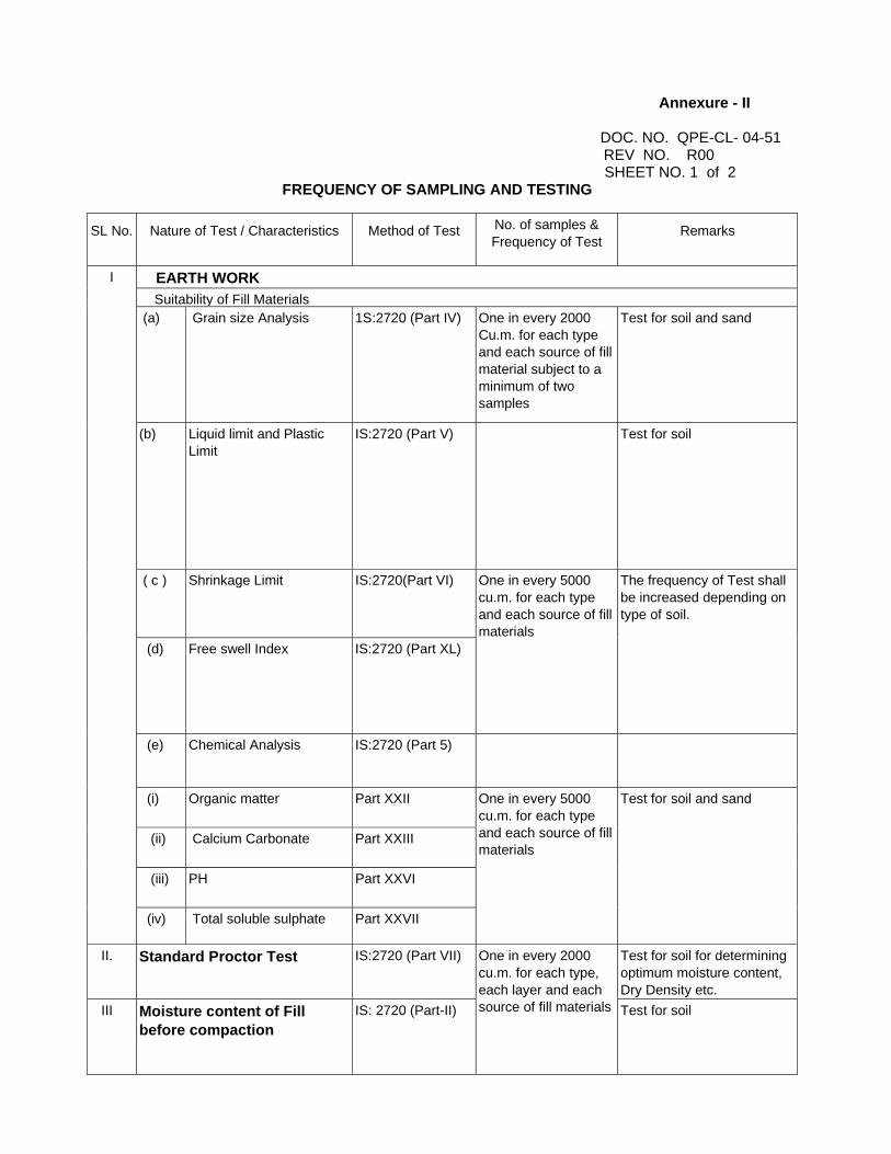
Annexure - II
DOC. NO. QPE-CL- 04-51 REV NO. R00
SHEET NO. 1 of 2 FREQUENCY OF SAMPLING AND TESTING
SL No.
Nature of Test / Characteristics
Method of Test
No. of samples & Frequency of Test
Remarks
EARTH WORK Suitability of Fill Materials (a) Grain size Analysis
1S:2720 (Part IV)
One in every 2000 Cu.m. for each type and each source of fill material subject to a minimum of two samples
Test for soil and sand
(b) Liquid limit and Plastic Limit
IS:2720 (Part V)
Test for soil
( c ) Shrinkage Limit IS:2720(Part VI)
(d) Free swell Index IS:2720 (Part XL)
One in every 5000 cu.m. for each type and each source of fill materials
The frequency of Test shall be increased depending on type of soil.
(e) Chemical Analysis IS:2720 (Part 5)
(i) Organic matter Part XXII
(ii) Calcium Carbonate Part XXIII
(iii) PH Part XXVI
I
(iv) Total soluble sulphate Part XXVII
One in every 5000 cu.m. for each type and each source of fill materials
Test for soil and sand
II. Standard Proctor Test IS:2720 (Part VII) Test for soil for determining optimum moisture content, Dry Density etc.
III Moisture content of Fill before compaction
IS: 2720 (Part-II)
One in every 2000 cu.m. for each type, each layer and each source of fill materials Test for soil

Annexure - II
DOC. NO. QPE-CL–04-51
REV NO. R00 SHEET NO. 2 of 2
FREQUENCY OF SAMPLING AND TESTING
SL No.
Nature of Test / Characteristics
Method of Test
No. of samples & Frequency of Test
Remarks
Degree of compaction of fill
a) Dry density by core cutter method OR Dry density implace by sand displacement methods
IS:2720 (Part XXIX) IS:2720 (Part XXVIII)
i. For foundation filling one for every ten foundations for each compacted layer for location of important and heavily loaded foundations.
ii. For each filling, one
for every 1000 sq.m. area for each compacted layer.
Test for soil
b) Relative density Index
IS:2720 (Part XIV)
-do- (I) & (ii)
Test for sand
c) Dry Density by proctor needle-penetration.
Standard Practice
Random checks to be carried out for each compacted layer in addition to tests mentioned under IV (a) above.
Test for soil.
IV
d) Permeability Test .
Standard Practice Random checks
.Test for soil
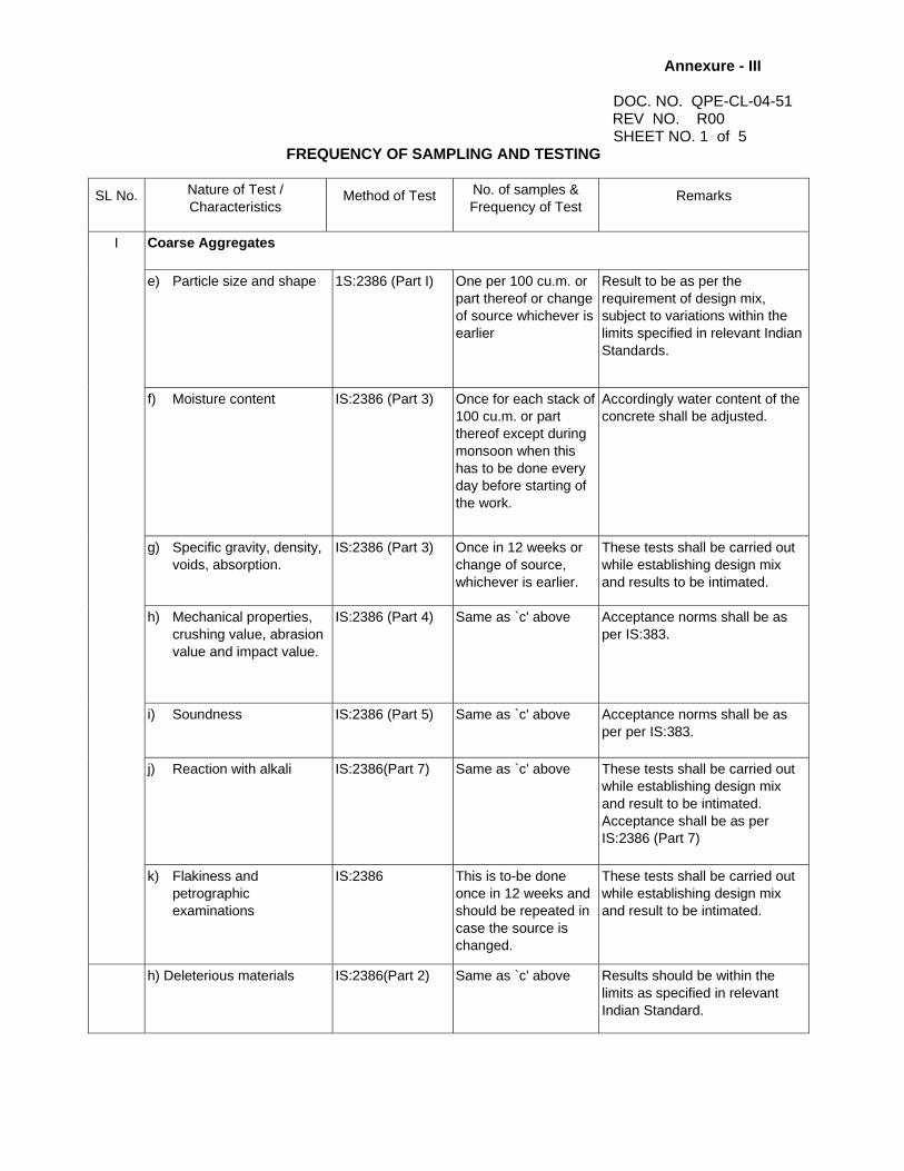
Annexure - III
DOC. NO. QPE-CL-04-51 REV NO. R00
SHEET NO. 1 of 5 FREQUENCY OF SAMPLING AND TESTING
SL No.
Nature of Test / Characteristics
Method of Test
No. of samples & Frequency of Test
Remarks
Coarse Aggregates
e) Particle size and shape
1S:2386 (Part I)
One per 100 cu.m. or part thereof or change of source whichever is earlier
Result to be as per the requirement of design mix, subject to variations within the limits specified in relevant Indian Standards.
f) Moisture content
IS:2386 (Part 3)
Once for each stack of 100 cu.m. or part thereof except during monsoon when this has to be done every day before starting of the work.
Accordingly water content of the concrete shall be adjusted.
g) Specific gravity, density, voids, absorption.
IS:2386 (Part 3)
Once in 12 weeks or change of source, whichever is earlier.
These tests shall be carried out while establishing design mix and results to be intimated.
h) Mechanical properties, crushing value, abrasion value and impact value.
IS:2386 (Part 4)
Same as `c' above
Acceptance norms shall be as per IS:383.
i) Soundness
IS:2386 (Part 5)
Same as `c' above
Acceptance norms shall be as per per IS:383.
j) Reaction with alkali
IS:2386(Part 7)
Same as `c' above
These tests shall be carried out while establishing design mix and result to be intimated. Acceptance shall be as per IS:2386 (Part 7)
I
k) Flakiness and petrographic examinations
IS:2386
This is to-be done once in 12 weeks and should be repeated in case the source is changed.
These tests shall be carried out while establishing design mix and result to be intimated.
h) Deleterious materials
IS:2386(Part 2)
Same as `c' above
Results should be within the limits as specified in relevant Indian Standard.
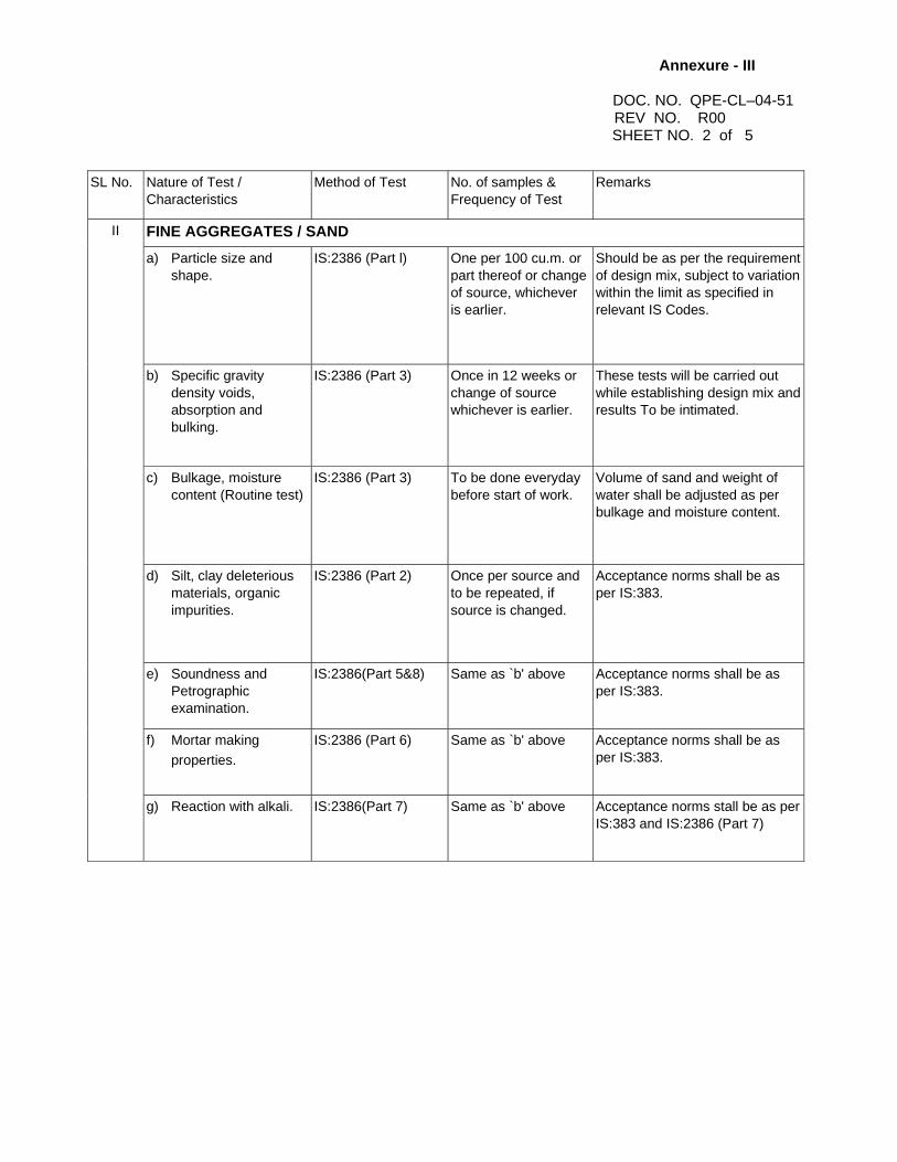
Annexure - III
DOC. NO. QPE-CL–04-51 REV NO. R00 SHEET NO. 2 of 5
SL No.
Nature of Test / Characteristics
Method of Test
No. of samples & Frequency of Test
Remarks
FINE AGGREGATES / SAND a) Particle size and
shape.
IS:2386 (Part l)
One per 100 cu.m. or part thereof or change of source, whichever is earlier.
Should be as per the requirement of design mix, subject to variation within the limit as specified in relevant IS Codes.
b) Specific gravity density voids, absorption and bulking.
IS:2386 (Part 3)
Once in 12 weeks or change of source whichever is earlier.
These tests will be carried out while establishing design mix and results To be intimated.
c) Bulkage, moisture content (Routine test)
IS:2386 (Part 3)
To be done everyday before start of work.
Volume of sand and weight of water shall be adjusted as per bulkage and moisture content.
d) Silt, clay deleterious materials, organic impurities.
IS:2386 (Part 2)
Once per source and to be repeated, if source is changed.
Acceptance norms shall be as per IS:383.
e) Soundness and Petrographic examination.
IS:2386(Part 5&8)
Same as `b' above
Acceptance norms shall be as per IS:383.
f) Mortar making properties.
IS:2386 (Part 6)
Same as `b' above
Acceptance norms shall be as per IS:383.
II
g) Reaction with alkali.
IS:2386(Part 7)
Same as `b' above
Acceptance norms stall be as per IS:383 and IS:2386 (Part 7)

Annexure - I
DOC. NO. QPE - CL – 04-51 REV. NO. R00
SHEET NO. 3 OF 5
SL No.
Nature of Test / Characteristics
Method of Test
No. of samples & Frequency of Test
Remarks
CEMENT
a. Setting time
IS:4031
One sample from each batch received from stores.
Acceptance norms shall be as per relevant Indian Standard.
III
b. Compressive Strength
c. Fineness
IS:4031
One sample from each batch received from stores.
Acceptance norms shall be as per relevant Indian Standard.
WATER IV.
Harmful substances, pH value, initial setting time, compressive strength.
IS-3025, IS:4031 & IS:516
Once a month for each source
Acceptance norms shall be as per CI.4.3 of IS:456 1978.
CONCRETE
a) Workability (Slump and compaction factor).
IS: 1199
One sample every two hours from every mixing plant.
Acceptance norms shall be as per CI.6.1 of IS:456 1978.
i) As per Cl. 14.2.2 of IS:456-1978 for initial period.
Acceptance criteria shall be as per CI.15 of IS:456-1978.
b) Crushing Strength
IS:516
ii) 0ne sample of six cubes per 150 cu.m. or part thereof for mass concrete for subsequent period.
A minimum of 3 (Part-7) specimens shall be tested for 28 days strength.
c) Water cement ratio.
IS:1199
At random at the time of batching.
According to mix design.
d) Cement Content
IS:1199
At random at the time of batching.
According to mix design.
e) Water-tightness test (for water retaining Structures).
IS:370
Each tank or reservoir.
Acceptance criteria as per specification & relevant IS codes.
V.
f) Finished:-dimensions
Physical measurement
All structures
Acceptance as per Specifications.
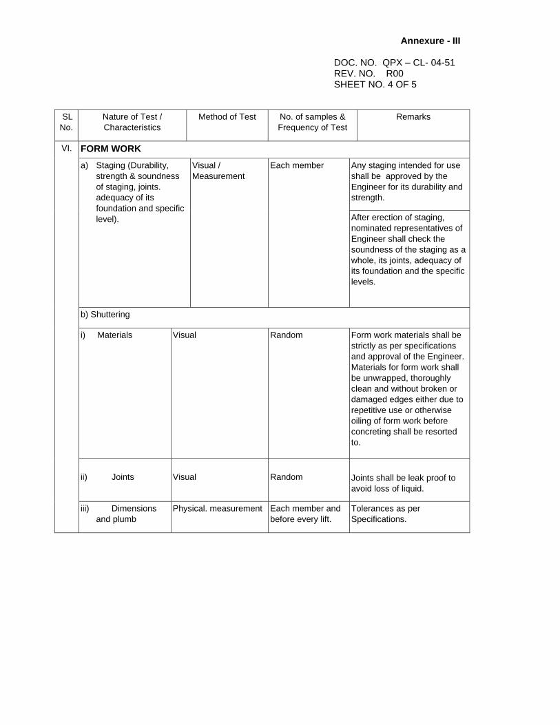
Annexure - III
DOC. NO. QPX – CL- 04-51 REV. NO. R00 SHEET NO. 4 OF 5
SL No.
Nature of Test / Characteristics
Method of Test
No. of samples & Frequency of Test
Remarks
FORM WORK Any staging intended for use shall be approved by the Engineer for its durability and strength.
a) Staging (Durability, strength & soundness of staging, joints. adequacy of its foundation and specific level).
Visual / Measurement
Each member
After erection of staging, nominated representatives of Engineer shall check the soundness of the staging as a whole, its joints, adequacy of its foundation and the specific levels.
b) Shuttering
i) Materials
Visual
Random
Form work materials shall be strictly as per specifications and approval of the Engineer. Materials for form work shall be unwrapped, thoroughly clean and without broken or damaged edges either due to repetitive use or otherwise oiling of form work before concreting shall be resorted to.
ii) Joints
Visual
Random
Joints shall be leak proof to avoid loss of liquid.
VI.
iii) Dimensions and plumb
Physical. measurement
Each member and before every lift.
Tolerances as per Specifications.
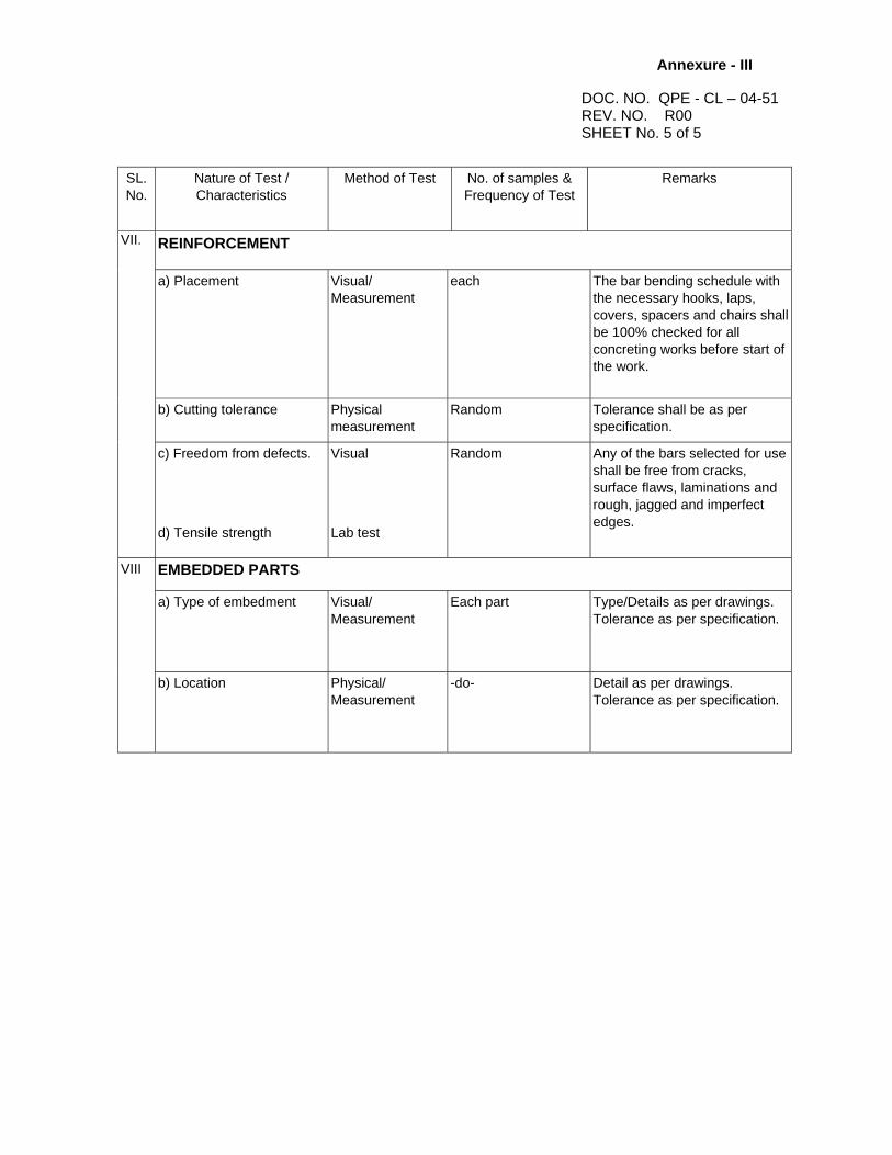
Annexure - III
DOC. NO. QPE - CL – 04-51 REV. NO. R00 SHEET No. 5 of 5
SL. No.
Nature of Test / Characteristics
Method of Test
No. of samples & Frequency of Test
Remarks
REINFORCEMENT a) Placement
Visual/ Measurement
each
The bar bending schedule with the necessary hooks, laps, covers, spacers and chairs shall be 100% checked for all concreting works before start of the work.
b) Cutting tolerance
Physical measurement
Random
Tolerance shall be as per specification.
VII.
c) Freedom from defects. d) Tensile strength
Visual Lab test
Random
Any of the bars selected for use shall be free from cracks, surface flaws, laminations and rough, jagged and imperfect edges.
EMBEDDED PARTS
a) Type of embedment
Visual/ Measurement
Each part
Type/Details as per drawings. Tolerance as per specification.
VIII
b) Location
Physical/ Measurement
-do-
Detail as per drawings. Tolerance as per specification.

Annexure - IV
DOC. NO. QPE - CL – 04-51 REV. NO. R00 SHEETNO. 1 of 1
METHOD FOR DETERMINATION OF SLUMP OF CONCRETE
Slump test As per IS 1199 Objective : To determine the consistency of fresh concrete and to check the uniformity
of concrete from batch to batch. Test Procedure 1. Internal surface and mould should be cleaned thoroughly to make it free from
moisture and any set concrete.
2. Place the mould on levelled metal plate.
3. The internal surface of the mould (cone) shall be thoroughly cleaned and free from superfluous moisture and any set concrete.
4. The mould shall be placed on a smooth, horizontal rigid and non-absorbent surface
(such as carefully levelled metal plate)
5. Cone shall be filled in four layers, each approximately one Quarter of the height of the mould.
6. Each layer shall be tamped with 25 strokes of the rounded end of the tapping rod in
such a manner that the strokes are uniformly distributed over the cross section of the mould and for the second and subsequent layers the rod to be penetrated into the underlying layers.
7. After the top layer has been rodded the concrete shall be struck off level with a trowel
or tapping rod.
8. Leaked out mortar between the mould and the base plate is cleaned away.
9. The mould should be removed from the concrete immediately by raising it slowly and carefully in a vertical direction.
10. The slump shall be measured immediately. (The slump can be measured by keeping
the tamping rod on the inverted mould and thus measuring the difference between the height of the mould and that of the highest point of the specimen being tested).
NOTE:- i) The test is to be carried out at a place free from vibration or shock and within two
minutes of sampling.
ii) Slump specimen which collapsed or sheared off laterally should be rejected and another test should be carried out.
iii) Actual slump to be recorded in logsheet L-05

Annexure - V
DOC. NO. QPE - CL – 04-51 REV. NO. R00 SHEET NO. 1 of 1
METHOD FOR DETERMINING THE COMPRESSIVE STRENGTH OF CONCRETE CUBES
(IS 516)
a) Age Test : The age shall be calculated from the time of the addition of the water to the dry ingredients.
The testing shall be carried out at the age of 7 days and 28 days.
b) Number of Specimens :
Three specimen from different batches.
c) Procedure :
Specimens stored in water shall be tested immediately on removal from the water, in testing machine. The load shall be applied without shock and increased continuously at the rate of approx. 140 kg/ cm2/min, Until the resistance of the specimen to the increasing load breaks down and no greater load can be sustained. The maximum load applied to the specimen shall then be recorded.
d) Calculation :
Compressive Strength (kg / cm2) = Max. Load Applied / Cross-sectional area

Annexure - VI DOC.NO. QPE-CL-04-51 REV. NO. R00 SHEET No. 1 of 1
BOUGHT OUT ITEMS
Check the following bought out items for their specifications / IS codes before use
i. Teak wood
ii. Grout Materials
iii. Steel doors & Press steel door frames (IS 4351)
iv. Steel glazed windows
v. Glass for glazing of doors & windows & partition work
vi. Aluminium partition, doors, windows (IS:1548)
vii. Rolling shutters
viii. Water proofing cement paint
ix. Alkali / Acid resistant resin based epoxy paint
x. Fire resistant paint
xi. Anto-corrosive bituminastic paint
xii. Acid resistance bricks
xiii. Asbestos Mill board
xiv. Asbestos rope
xv. Mineral wool
xvi. Vineertax
xvii. Marine Terrazo flooring / Cement Concrete flooring (granolithic & ironite)
xviii. Glazed / Ceramic / tiles flooring, wall cladding
xix. Flexivinyle lining / PVC tiles
xx. Heavy duty water proofing treatment on roof
xxi. Under desk insulation & aluminium false ceiling materials
xxii. Galvanised pipeline for water supply including fittings, C I pipes, RCC non-pressure pipes
xxiii. Coarse aggregate
xxiv. Fine aggregate
xxv. Reinforcement
xxvi. Cement
Note :-
1) Customer may witness the tests at manufacturers' premises or at laboratory as and when felt necessary.


PSER
RECORD OF QUALITY CHECKS
SHEET NO. OF QPI
CHECK
NO.
RESULTS ACHIEVED OK / NOT
OK
DRAWING / DOCUMENT REFERENCE
FORMAT OF
RECORD
CHECKED BY SIGN. & DATE
ACCEPTED BY SIGN. & DATE
REMARKS
Note : Any protocol made is to be numbered & mentioned in “Format of Record” column.
DOC. NO. QPE - CL – 04-51
PROJECT
SYSTEM
SUB-SYSTEM
AREA
REV. NO. R00
UNIT NO.
LOG SHEETNO. L-00
RATING
SHEET / SHEETS
FMT-QP-007 REV. 00
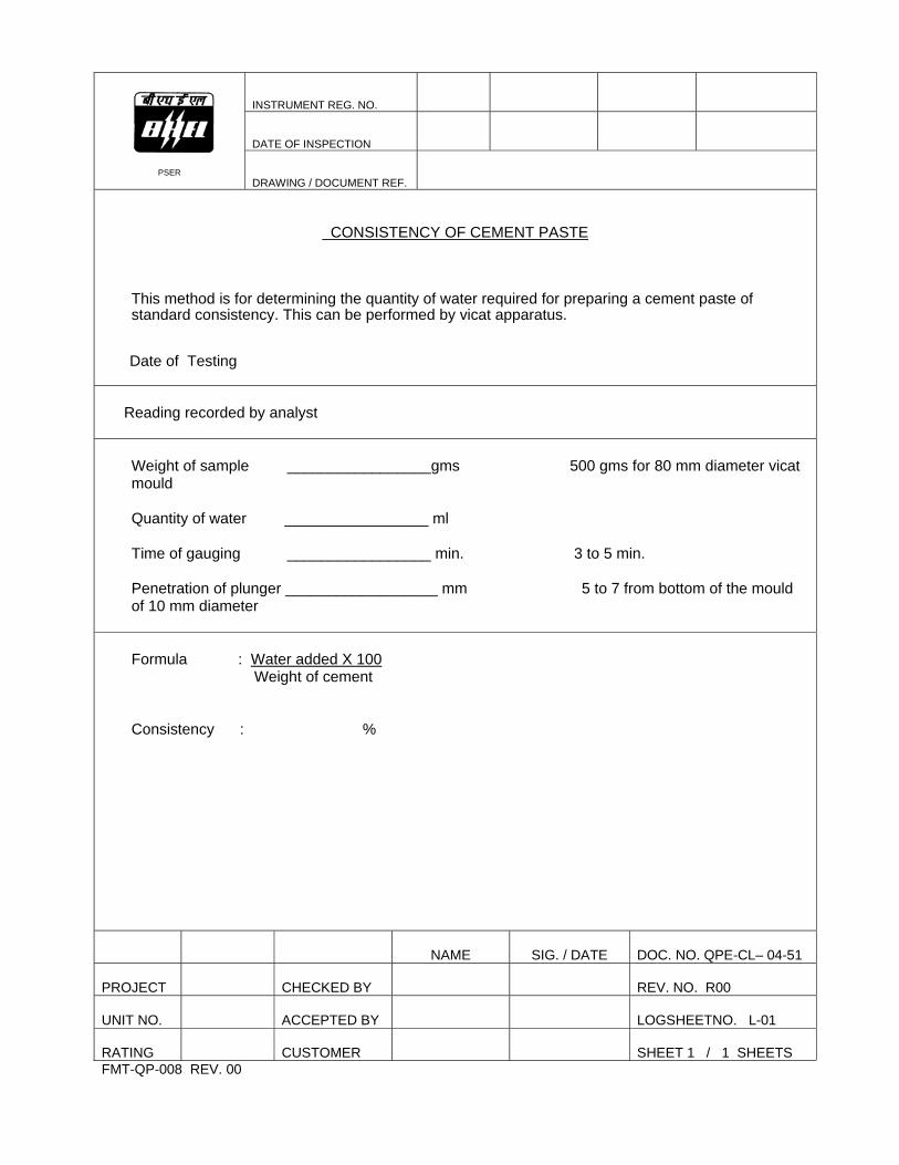
INSTRUMENT REG. NO.
DATE OF INSPECTION
PSER
DRAWING / DOCUMENT REF.
CONSISTENCY OF CEMENT PASTE
This method is for determining the quantity of water required for preparing a cement paste of standard consistency. This can be performed by vicat apparatus.
Date of Testing
Reading recorded by analyst
Weight of sample _________________gms 500 gms for 80 mm diameter vicat mould Quantity of water _________________ ml Time of gauging _________________ min. 3 to 5 min. Penetration of plunger __________________ mm 5 to 7 from bottom of the mould of 10 mm diameter Formula : Water added X 100 Weight of cement Consistency : %
NAME
SIG. / DATE
DOC. NO. QPE-CL– 04-51
PROJECT
CHECKED BY
REV. NO. R00
UNIT NO.
ACCEPTED BY
LOGSHEETNO. L-01
RATING
CUSTOMER
SHEET 1 / 1 SHEETS
FMT-QP-008 REV. 00
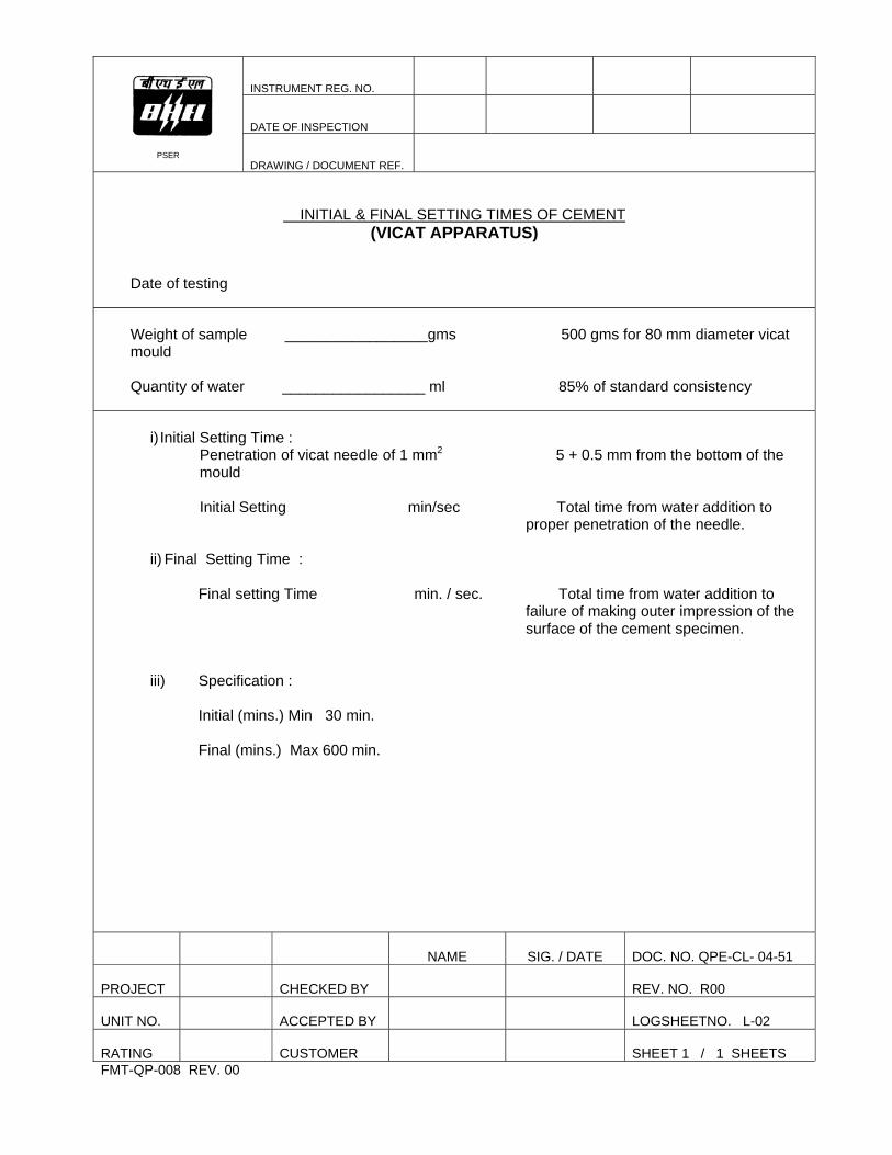
INSTRUMENT REG. NO.
DATE OF INSPECTION
PSER
DRAWING / DOCUMENT REF.
INITIAL & FINAL SETTING TIMES OF CEMENT (VICAT APPARATUS)
Date of testing
Weight of sample _________________gms 500 gms for 80 mm diameter vicat mould Quantity of water _________________ ml 85% of standard consistency
i) Initial Setting Time : Penetration of vicat needle of 1 mm2 5 + 0.5 mm from the bottom of the mould Initial Setting min/sec Total time from water addition to
proper penetration of the needle.
ii) Final Setting Time :
Final setting Time min. / sec. Total time from water addition to failure of making outer impression of the surface of the cement specimen.
iii) Specification : Initial (mins.) Min 30 min. Final (mins.) Max 600 min.
NAME
SIG. / DATE DOC. NO. QPE-CL- 04-51
PROJECT
CHECKED BY
REV. NO. R00
UNIT NO.
ACCEPTED BY
LOGSHEETNO. L-02
RATING
CUSTOMER
SHEET 1 / 1 SHEETS
FMT-QP-008 REV. 00
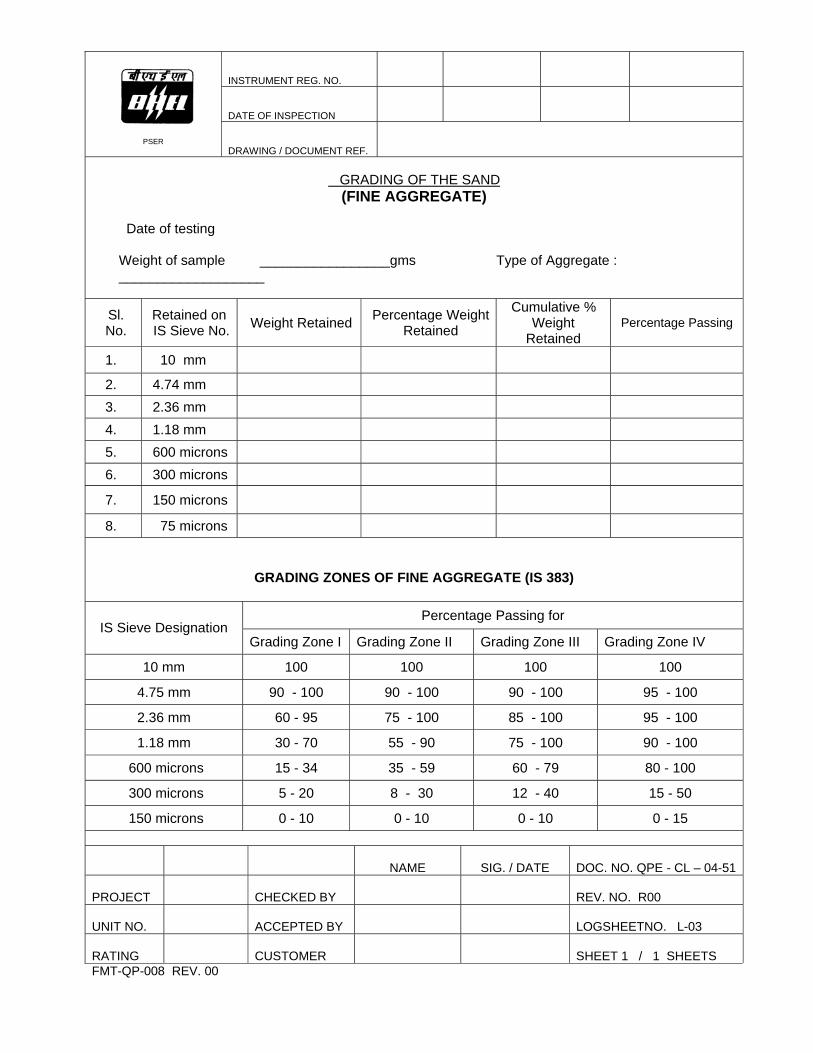
INSTRUMENT REG. NO.
DATE OF INSPECTION
PSER
DRAWING / DOCUMENT REF.
GRADING OF THE SAND
(FINE AGGREGATE)
Date of testing
Weight of sample _________________gms Type of Aggregate : ___________________
Sl. No.
Retained on IS Sieve No. Weight Retained Percentage Weight
Retained
Cumulative % Weight
Retained Percentage Passing
1. 10 mm
2. 4.74 mm
3. 2.36 mm
4. 1.18 mm
5. 600 microns
6. 300 microns
7. 150 microns
8. 75 microns
GRADING ZONES OF FINE AGGREGATE (IS 383) Percentage Passing for
IS Sieve Designation Grading Zone I Grading Zone II Grading Zone III Grading Zone IV
10 mm 100 100 100 100
4.75 mm 90 - 100 90 - 100 90 - 100 95 - 100
2.36 mm 60 - 95 75 - 100 85 - 100 95 - 100
1.18 mm 30 - 70 55 - 90 75 - 100 90 - 100
600 microns 15 - 34 35 - 59 60 - 79 80 - 100
300 microns 5 - 20 8 - 30 12 - 40 15 - 50
150 microns 0 - 10 0 - 10 0 - 10 0 - 15
NAME
SIG. / DATE DOC. NO. QPE - CL – 04-51
PROJECT
CHECKED BY
REV. NO. R00
UNIT NO.
ACCEPTED BY
LOGSHEETNO. L-03
RATING
CUSTOMER
SHEET 1 / 1 SHEETS
FMT-QP-008 REV. 00
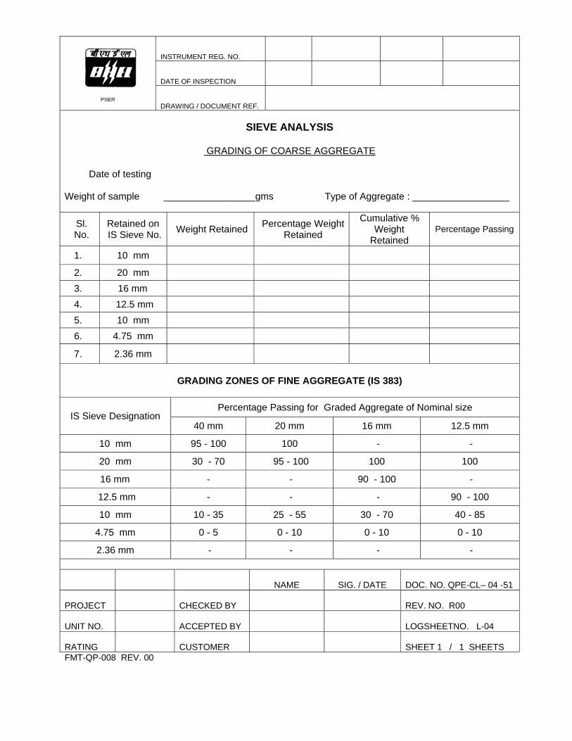
INSTRUMENT REG. NO.
DATE OF INSPECTION
PSER
DRAWING / DOCUMENT REF.
SIEVE ANALYSIS
GRADING OF COARSE AGGREGATE
Date of testing Weight of sample _________________gms Type of Aggregate : __________________
Sl. No.
Retained on IS Sieve No. Weight Retained Percentage Weight
Retained
Cumulative % Weight
Retained Percentage Passing
1. 10 mm
2. 20 mm
3. 16 mm
4. 12.5 mm
5. 10 mm
6. 4.75 mm
7. 2.36 mm
GRADING ZONES OF FINE AGGREGATE (IS 383)
Percentage Passing for Graded Aggregate of Nominal size
IS Sieve Designation 40 mm 20 mm 16 mm 12.5 mm
10 mm 95 - 100 100 - -
20 mm 30 - 70 95 - 100 100 100
16 mm - - 90 - 100 -
12.5 mm - - - 90 - 100
10 mm 10 - 35 25 - 55 30 - 70 40 - 85
4.75 mm 0 - 5 0 - 10 0 - 10 0 - 10
2.36 mm - - - -
NAME
SIG. / DATE DOC. NO. QPE-CL– 04 -51
PROJECT
CHECKED BY
REV. NO. R00
UNIT NO.
ACCEPTED BY
LOGSHEETNO. L-04
RATING
CUSTOMER
SHEET 1 / 1 SHEETS
FMT-QP-008 REV. 00

INSTRUMENT REG. NO.
DATE OF INSPECTION
PSER
DRAWING / DOCUMENT REF.
COMPRESSIVE STRENGTH OF CEMENT CONCRETE
Name of Agency : Location / Structure : Grade of Concrete Mix Proportion :
Compression Strength / mm2
Sl. No.
Date of
Casting
Cube Identification Mark
Slump (mm)
Concrete Quantity from
which sampling done
Date of
Testing
Age of
Cube
Weight of Cube Individual Average
Remarks
NAME
SIGNATURE / DATE
DOC. NO. QPE - CL – 04-51
PROJECT
CHECKED BY
REV. NO. R00
UNIT NO.
ACCEPTED BY
LOG SHEET NO. L-05
RATING
CUSTOMER
SHEET 1 / 1 SHEETS
FMT-QP-009 REV. 00