bharat heavy electricals limited · tamil nadu transmission corporation limited bharat heavy...
TRANSCRIPT

BHARAT HEAVY ELECTRICALS LIMITED TRANSMISSION BUSINESS ENGINEERING MANAGEMENT
NEW DELHI DOCUMENT No. TB-363-510-013 Rev 00 Prepared Checked Approved
CO
PYR
IGH
T &
CO
NFI
DEN
TIA
L TH
E IN
FOR
MA
TIO
N C
ON
TAIN
ED IN
TH
IS D
OCU
MEN
T IS
TH
E PR
OPE
RTY
OF
BH
AR
AT
HEA
VY
ELE
CTR
ICA
LS L
IMIT
ED
THIS
MU
ST N
OT
BE U
SED
DIR
ECTL
Y O
R IN
DIR
ECTL
Y I
N A
NY
MA
NN
ER D
ETR
IMEN
TAL
TO T
HE
INTE
RES
T O
F TH
E CO
MPA
NY
CUSTOMER Doc. No. NAME BA VK RS TYPE OF DOC. TECHNICAL SPECIFICATION SIGN TITLE DATE 01.11.13 01.11.13 01.11.13 POWER LINE CARRIER COMMUNICATION GROUP TBEM W.O. No 83003 CUSTOMER TAMIL NADU TRANSMISSION CORPORATION LIMITED PROJECT 400/110 KV Substation at Thappagundu
& 400/230-110 KV Substation at Anikadavu
List of Contents No. of Pages Cover Sheet 01 Section 1 Scope, Specific technical requirements & Quantities 04 Section 2 Equipment Specification 24 Section 3 General Technical Requirement 14
Appendix – A (NO DEVIATION Certificate) Appendix - B (Bidder’s Undertaking for Type Tests to be
furnished with offer) Section 4 Guaranteed Technical Particulars 13
Rev. Date Altered Checked Approved REVISION DETAILS Distribution CUSTOMER TBMM O/C -

Tamil Nadu Transmission Corporation Limited Bharat Heavy Electricals Limited 400/110 KV S/STN at Thappagundu & 400/230‐110 KV S/STN at Anikadavu TB‐363‐510‐013 Technical specification for Power Line Carrier Communication Rev No. 00
Page 1 of 4
SECTION – 1
SCOPE, SPECIFIC TECHNICAL REQUIREMENT AND QUANTITIES
1. SCOPE
This technical specification covers the requirements of design, manufacture, testing at works, packing, dispatch, supervision of Installation, Testing and Commissioning of Power Line Communication Equipment (PLCC) and its associated accessories. The offered equipment shall also comply with the General Technical Requirements for the project as detailed under section-3 of this specification. For environmental conditions, refer Section-3 carefully The specification comprise of following sections:
Section-1: Scope, specific technical requirements & Bill of Quantities. Section-2: Equipment specifications Section-3: General technical requirements for all equipments under the project. Section-4: Guaranteed Technical Particulars In case of any conflict between various sections, order of precedence shall be in the same order as listed above. The equipment is required for the following projects: Name of the Customer : M/s Tamil Nadu Transmission Corporation Limited Name of the Project : 400/110kV S/S at Thappagundu
400/230-110 KV Substation at Anikadavu
2. SPECIFIC TECHNICAL REQUIREMENTS
For detailed equipment specification of Power Line Communication Equipment (PLCC) and its associated accessories, refer to Section -2 of the document

Tamil Nadu Transmission Corporation Limited Bharat Heavy Electricals Limited 400/110 KV S/STN at Thappagundu & 400/230‐110 KV S/STN at Anikadavu TB‐363‐510‐013 Technical specification for Power Line Carrier Communication Rev No. 00
Page 2 of 4
3. BILL OF QUANTITIES (Station –wise breakup) A. 400/110 kV THAPAGUNDU S/STN
S. No Description as per TANTRANSCO BOQ Unit
Quantity
1. Digital protection Coupler (8 Command) Nos. 2
2. EPAX for PLCC System 48 subscribers and 16 trunks Nos. 1
3. 110 KV Coupling Devices Nos. 8
4. 110 KV Carrier set (10 watts output) Nos. 8
5. Coaxial Cable for 230 / 110 KV PLCC link Km 2
6. 1 pair un-armoured telephone cable Km 2
7. 4 pair un-armoured telephone cable Km 0.5
8. Site Testing and Commissioning of PLCC Equipment Links 10
B. 400/230/110 kV ANIKADAVU S/STN
S. No Description as per TANTRANSCO BOQ Unit
Quantity
1. Digital protection Coupler(8 Command) Nos. 6
2 EPAX for PLCC System 48 subscribers and 16 trunks Nos. 1
3 230 KV Coupling Devices Nos. 6
4 230 KV Protection coupler Digital (8 Command) Nos. 6
5 230 KV Carrier Set (Programmable single band carrier set - 40 watts output)
Nos. 6
6 110 KV Coupling Devices Nos. 4
7 110 KV Carrier set(10 watts output) Nos. 4
8 Coaxial Cable for 230 / 110 KV PLCC link Km 2

Tamil Nadu Transmission Corporation Limited Bharat Heavy Electricals Limited 400/110 KV S/STN at Thappagundu & 400/230‐110 KV S/STN at Anikadavu TB‐363‐510‐013 Technical specification for Power Line Carrier Communication Rev No. 00
Page 3 of 4
9 1 pair un-armoured telephone cable Km 2
10 4 pair un-armoured telephone cable Km 0.5
11 Site Testing and Commissioning of PLCC Equipment Links 14
Notes: 1. S. No. 1 of the BOQ means Panel Mounted digital protection couplers (8 Commands)
complete with its Power Supply Module. 2. EPAX for PLCC system shall be suitable for 48 Subscribers and 16 Trunk lines. 3. 230kV Coupling Devices are Ph-Ph type whereas 110kV Coupling devices are Ph-E
type. 4. HF coaxial cable is 75 Ohms Un-balanced and is to be supplied in drum lengths of
1000m ± 5%. 5. There may be a quantity variation of up to -10% to +30% in the Bill of Quantity of
Cables.
4. TYPE TESTING
The Type Test as per relevant IS/IEC for offered equipments/materials used for this project should have been conducted in any approved Government/Govt. recognized laboratories conforming to latest IS/IEC. The above type test certificates should accompany the drawings of the materials equipments, duly signed under seal by the Institution, who have issued the type test certificate.
The above type test should have been conducted not earlier than five (5) years as on the date of technical bid opening, which is 05/4/2013 for Anikadavu & 10/4/2013 for Thappagundu substations.
The copies of type test certificates shall be furnished for verification during contract execution stage.
Non furnishing of type test certificates by the tenderers, will be liable for rejection.
5. TECHNICAL QUALIFYING REQUIREMENT The qualified manufacturer should have manufactured, Type tested and supplied at least 50% of the required quantity of the PLCC Equipment and accessories of same rating to any of the 420KV/220kV / 132kV Switchyards of Electricity Boards/Power Utilities in India in any one year during the last five years. The same should have been in satisfactory operation for a minimum period of two years as on date of technical bid opening, which is 05/4/13 for Anikadavu & 10/4/13 for Thappagundu substations.
Tamil Nadu Transmission Corporation Limited Bharat Heavy Electricals Limited 400/110 KV S/STN at Thappagundu & 400/230‐110 KV S/STN at Anikadavu TB‐363‐510‐013 Technical specification for Power Line Carrier Communication Rev No. 00
Page 4 of 4
6. QUALITY PLAN
Bidder to follow valid TANTRANSCO approved Quality Plan as per TANTRANSCO procedure. In case the bidder doesn’t have approved QP, it will be the bidder’s responsibility to get its QP approved directly from the ultimate customer.

Tamil Nadu Transmission Corporation Limited Bharat Heavy Electricals Limited 400/110 KV S/STN at Thappagundu & 400/230‐110 KV S/STN at Anikadavu TB‐363‐510‐013 Technical specification for Power Line Carrier Communication Rev No. 00
1
SECTION – 2
EQUIPMENT SPECIFICATION
As per TAN TRANSCO SPECIFICATION ENCLOSED HERE IN

SECTION - 22
PLCC CARRIER SETS AND PROTECTION COUPLERS
1.0 SCOPE: 1.1 This specification provides for design, manufacture, inspection and testing
before despatch of Power Line Carrier equipment along with accessories for establishing Power Line Carrier Communication Links in different substations/feeders.
1.2 The Power Line Carrier Communication equipments along with accessories shall conform in all respects to high standards of engineering design, workmanship with latest state of art and latest revisions of relevant standards at the time of offer and the purchaser shall have the power to reject any work or material, which in his judgement is not in full accordance therewith. The material used for manufacture of the equipment shall be of best class and capable of satisfactory operation in tropics with humid atmospheric condition without distortion or deterioration.
2.0 STANDARDS: 2.1 Unless otherwise specified elsewhere in the specification, the Power Line
Carrier Communication Indoor equipment along with accessories shall conform to the latest revisions and amendments thereof, of the following standards/Technical Particulars. I. INDOOR EQUIPMENTS:
1.Carrier set : IS 10706 - 1983 IS 9482 - 1980 IEC 495 -1993
2.2 Equipment meeting with the requirements of other authoritative
International standards which ensure equal or better performance than the standards mentioned above, shall also be considered. When the equipment offered by the supplier conforms to other standards, salient points of difference between standards adopted and the standards in this specification shall be clearly brought out in the offer.
3.0 PRINCIPAL PARAMETERS:
The Power Line Carrier Communication equipments along with accessories covered in this specification shall meet the technical requirements listed hereunder.
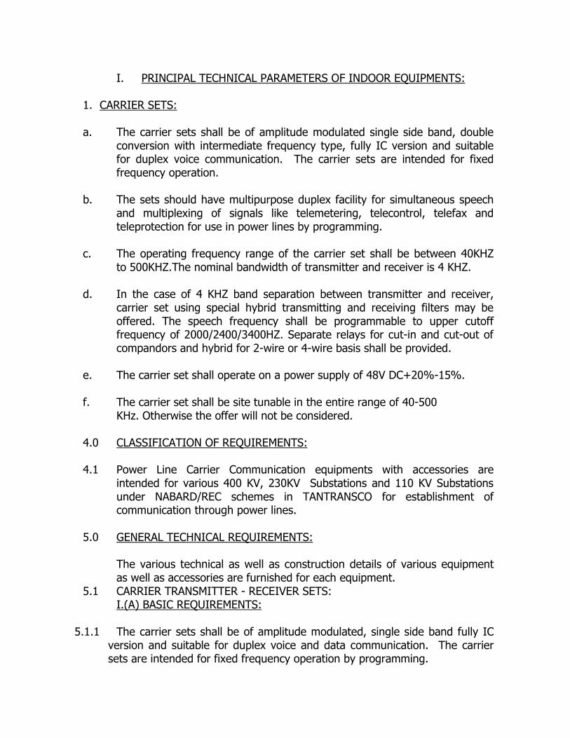
I. PRINCIPAL TECHNICAL PARAMETERS OF INDOOR EQUIPMENTS:
1. CARRIER SETS: a. The carrier sets shall be of amplitude modulated single side band, double
conversion with intermediate frequency type, fully IC version and suitable for duplex voice communication. The carrier sets are intended for fixed frequency operation.
b. The sets should have multipurpose duplex facility for simultaneous speech
and multiplexing of signals like telemetering, telecontrol, telefax and teleprotection for use in power lines by programming.
c. The operating frequency range of the carrier set shall be between 40KHZ
to 500KHZ.The nominal bandwidth of transmitter and receiver is 4 KHZ. d. In the case of 4 KHZ band separation between transmitter and receiver,
carrier set using special hybrid transmitting and receiving filters may be offered. The speech frequency shall be programmable to upper cutoff frequency of 2000/2400/3400HZ. Separate relays for cut-in and cut-out of compandors and hybrid for 2-wire or 4-wire basis shall be provided.
e. The carrier set shall operate on a power supply of 48V DC+20%-15%. f. The carrier set shall be site tunable in the entire range of 40-500 KHz. Otherwise the offer will not be considered. 4.0 CLASSIFICATION OF REQUIREMENTS: 4.1 Power Line Carrier Communication equipments with accessories are
intended for various 400 KV, 230KV Substations and 110 KV Substations under NABARD/REC schemes in TANTRANSCO for establishment of communication through power lines.
5.0 GENERAL TECHNICAL REQUIREMENTS:
The various technical as well as construction details of various equipment as well as accessories are furnished for each equipment.
5.1 CARRIER TRANSMITTER - RECEIVER SETS: I.(A) BASIC REQUIREMENTS:
5.1.1 The carrier sets shall be of amplitude modulated, single side band fully IC version and suitable for duplex voice and data communication. The carrier sets are intended for fixed frequency operation by programming.
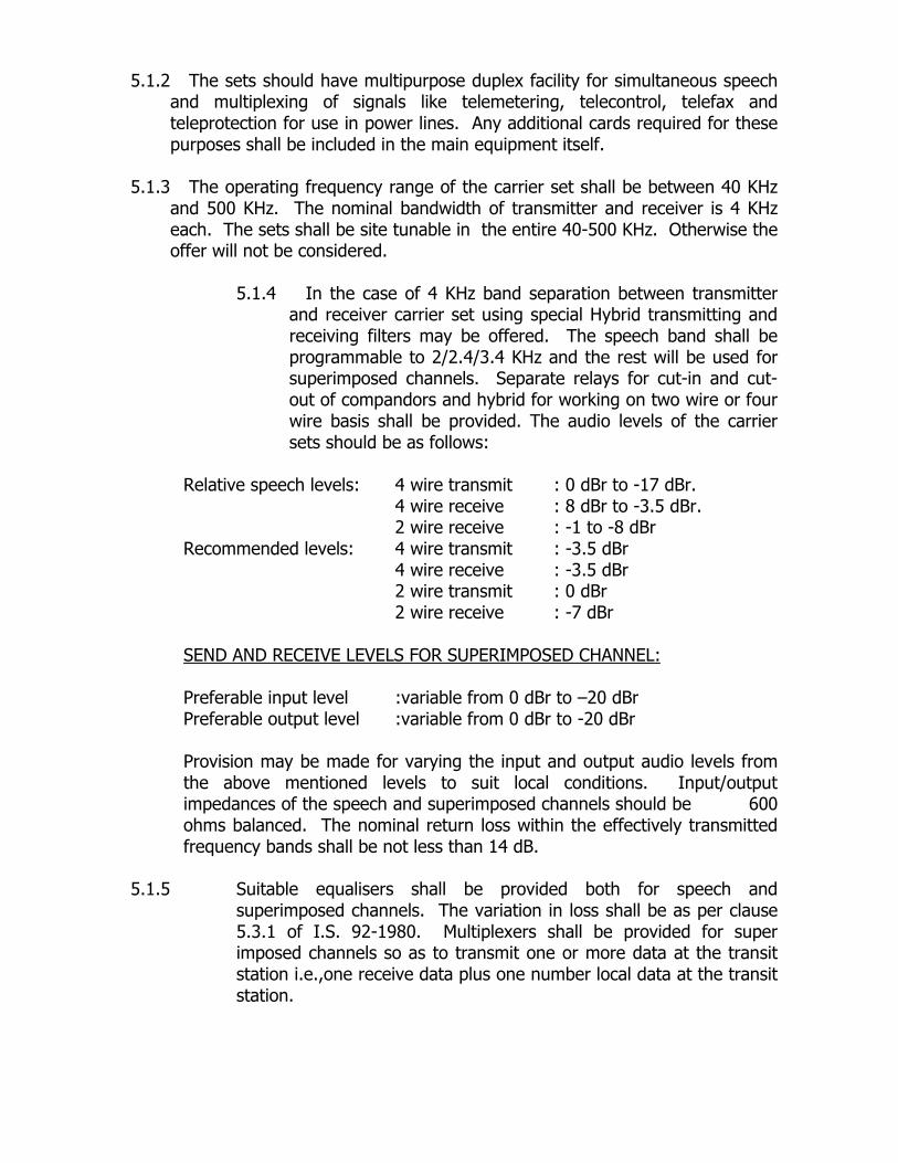
5.1.2 The sets should have multipurpose duplex facility for simultaneous speech and multiplexing of signals like telemetering, telecontrol, telefax and teleprotection for use in power lines. Any additional cards required for these purposes shall be included in the main equipment itself.
5.1.3 The operating frequency range of the carrier set shall be between 40 KHz
and 500 KHz. The nominal bandwidth of transmitter and receiver is 4 KHz each. The sets shall be site tunable in the entire 40-500 KHz. Otherwise the offer will not be considered.
5.1.4 In the case of 4 KHz band separation between transmitter
and receiver carrier set using special Hybrid transmitting and receiving filters may be offered. The speech band shall be programmable to 2/2.4/3.4 KHz and the rest will be used for superimposed channels. Separate relays for cut-in and cut-out of compandors and hybrid for working on two wire or four wire basis shall be provided. The audio levels of the carrier sets should be as follows:
Relative speech levels: 4 wire transmit : 0 dBr to -17 dBr. 4 wire receive : 8 dBr to -3.5 dBr. 2 wire receive : -1 to -8 dBr Recommended levels: 4 wire transmit : -3.5 dBr 4 wire receive : -3.5 dBr 2 wire transmit : 0 dBr 2 wire receive : -7 dBr SEND AND RECEIVE LEVELS FOR SUPERIMPOSED CHANNEL: Preferable input level :variable from 0 dBr to –20 dBr Preferable output level :variable from 0 dBr to -20 dBr Provision may be made for varying the input and output audio levels from the above mentioned levels to suit local conditions. Input/output impedances of the speech and superimposed channels should be 600 ohms balanced. The nominal return loss within the effectively transmitted frequency bands shall be not less than 14 dB.
5.1.5 Suitable equalisers shall be provided both for speech and
superimposed channels. The variation in loss shall be as per clause 5.3.1 of I.S. 92-1980. Multiplexers shall be provided for super imposed channels so as to transmit one or more data at the transit station i.e.,one receive data plus one number local data at the transit station.
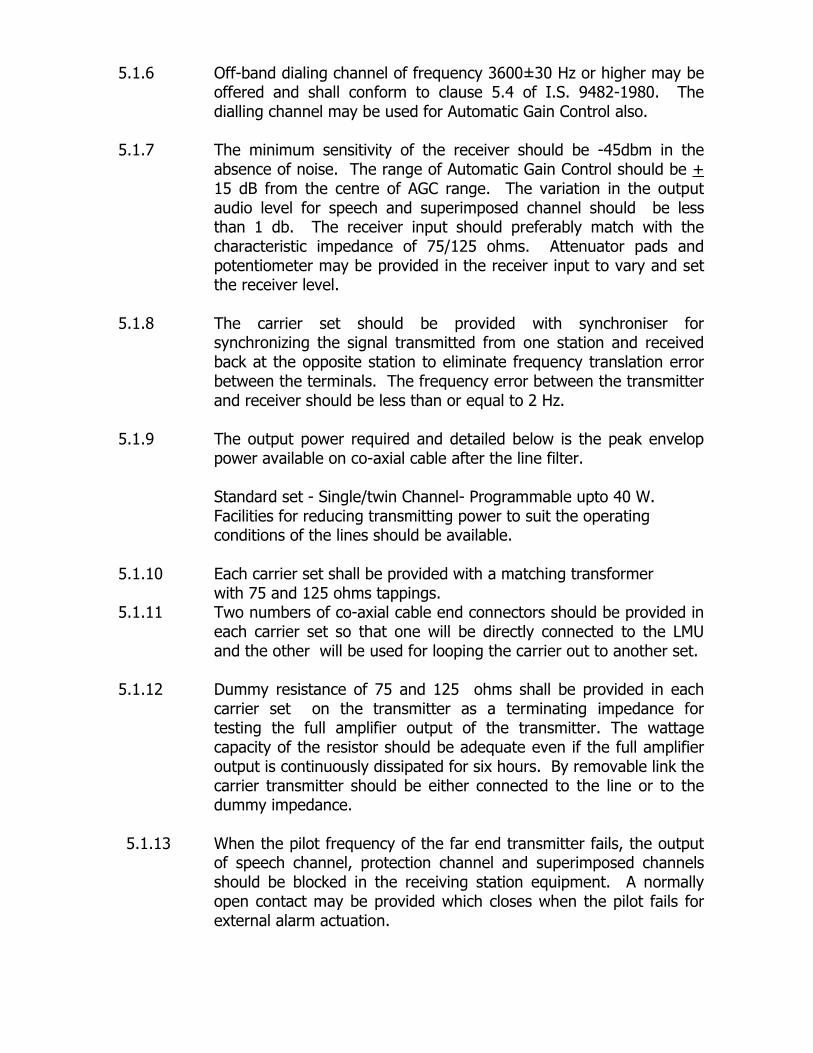
5.1.6 Off-band dialing channel of frequency 3600±30 Hz or higher may be offered and shall conform to clause 5.4 of I.S. 9482-1980. The dialling channel may be used for Automatic Gain Control also.
5.1.7 The minimum sensitivity of the receiver should be -45dbm in the
absence of noise. The range of Automatic Gain Control should be + 15 dB from the centre of AGC range. The variation in the output audio level for speech and superimposed channel should be less than 1 db. The receiver input should preferably match with the characteristic impedance of 75/125 ohms. Attenuator pads and potentiometer may be provided in the receiver input to vary and set the receiver level.
5.1.8 The carrier set should be provided with synchroniser for
synchronizing the signal transmitted from one station and received back at the opposite station to eliminate frequency translation error between the terminals. The frequency error between the transmitter and receiver should be less than or equal to 2 Hz.
5.1.9 The output power required and detailed below is the peak envelop
power available on co-axial cable after the line filter.
Standard set - Single/twin Channel- Programmable upto 40 W. Facilities for reducing transmitting power to suit the operating conditions of the lines should be available.
5.1.10 Each carrier set shall be provided with a matching transformer
with 75 and 125 ohms tappings. 5.1.11 Two numbers of co-axial cable end connectors should be provided in
each carrier set so that one will be directly connected to the LMU and the other will be used for looping the carrier out to another set.
5.1.12 Dummy resistance of 75 and 125 ohms shall be provided in each
carrier set on the transmitter as a terminating impedance for testing the full amplifier output of the transmitter. The wattage capacity of the resistor should be adequate even if the full amplifier output is continuously dissipated for six hours. By removable link the carrier transmitter should be either connected to the line or to the dummy impedance.
5.1.13 When the pilot frequency of the far end transmitter fails, the output
of speech channel, protection channel and superimposed channels should be blocked in the receiving station equipment. A normally open contact may be provided which closes when the pilot fails for external alarm actuation.

5.1.14 Removable links should be provided on the front panel in the speech two wire and four wire input and output circuit, the superimposed channels input and output circuit so that the equipment can be de-coupled easily while testing without opening the panel and desoldering the inner connecting wires. If any special type cable is required to inter connect the test instrument and the carrier set the same may be offered as optional item.
5.1.15 Built in AF oscillator with test print may be provided in each carrier set to
check as far as possible certain sections of AF, IF and RF section of the transmitter and receiver. If the above print is not normally to be inserted, but to be kept as a separate item, then it may be offered as optional item.
5.1.16 A test panel with monitor meter shall be built in to enable a rapid check of all the levels, various voltages etc., to facilitate periodic checking of the equipment at site. Alarm facilities shall be provided to indicate the pilot failure and fuse failure.
5.1.17 Built in point to point communication should be available in each
carrier set. Communication shall be established by merely inserting the hand set in the plug provided on front panel and then pressing a call push button. When the hand set is inserted the existing conversation if any should not be disturbed. The hand set should be merely in parallel with existing two or four wire communication. When the push button is pushed, the buzzer should sound and indication lamp should light (fixed on the top of the outside of the carrier set) at the opposite station.
5.1.18 The carrier transmitter and receiver should operate from battery of
nominal voltage 48V DC, positive grounded system.Since the battery is connected across a float charger, the voltage will vary from 51.5 to 56 volts. The D.C. voltage tolerance requirement is +20% to -15% and ripple peak to peak is < 5%. The carrier set should not get damaged and suitably protected for against these voltages as well as for transients/spikes. The input of the supply module should be provided with midget breaker of suitable rating.
This should operate and isolate the carrier set in the event of the following: 1. When the input voltage level increases beyond the set level. 2. When any of the stabilised voltage inside the carrier set
increases or decreases beyond the set range. 3. When the current drawn by the equipment increases beyond
the set range. 4. When there is accidental short across the output amplifier.
However very short duration voltage spikes should not trip this breaker and all the components should be well protected in this regard. Since the protection coupler

is to be connected to the carrier sets, each channel should have facility to cutoff speech and other selective superimposed channels and boost the carrier trip frequency output when trip command is received from the protection coupler. 5.1.19 The transistors and IC chips used in the carrier set shall be
guaranteed to give long and trouble free service under tropical conditions with a maximum ambient temperature of 50°C in relative humidity of 95% indoor.
5.1.20 The crystal used in the carrier sets for the oscillator circuits
should have transistorised automatic thermostat control unit including oven so as to give frequency stability of ±1 Hz (with oven ) or better.
5.1.21 The programmable carrier sets should be supplied with necessary
tuning accessories free of cost or otherwise for programming the sets. The complete details about the programmable sets should be furnished. I.(B) PHYSICAL CONSTRUCTION
5.1.22 The carrier equipment shall be housed in robust, adequately ventilated cabinet and shall be suitable for being mounted on the floor.
5.1.23 All instruments, control switches and wiring of the carrier set shall be
accessible through the front door so that the carrier cabinet can be installed close to the wall of the room where it is located.
5.1.24 One hand set may be provided for each equipment. 5.1.25 All the carrier sets shall be provided with vermin proof wire mesh at
the bottom, fixing bolts, rails if any for fixing the panel. 5.1.26 The cabinet door swing panel print racks and other metal parts not
directly welded to the main cabinet shall be earthed directly with a flexible lead to the earth terminal in the cabinet.
5.1.27 Two nos. 230V, AC plug points are to be provided inside the PLCC
terminal to connect soldering iron, measuring instruments etc. 5.1.28 A.C. and D.C. terminal blocks are to be provided separately inside
the PLC terminal on the L.H.S. and R.H.S. respectively with clear markings.

5.1.29 A suitable bulb holder with 60 watt bulb should be provided inside the top of the PLC terminal cabinet with ON/OFF switch to illuminate the inner side of the cabinet.
5.1.30 An exhaust fan rated for 230V AC only shall be provided on the top
of the carrier terminal irrespective of the type of power supply, power amplifier design and output power.
II. ADDITIONAL REQUIREMENTS 5.1.31 The carrier sets shall be provided with a compander device to
improve the quality of communication. 5.1.32 Programmable Transit Band Pass filters, shall be provided in the
receiver of each set in each channel so as to filter the superimposed channels by using digital filters. The TBF shall be programmable from 300-3800 Hz in steps of 60 Hz.
5.1.33 Disconnecting arrangement shall be provided in the transmitter for
the superimposed channel inputs in the AF side. The input level of each superimposed channel should be independently adjustable. The output should also be independently adjustable.
5.1.34 The transmit filter should be so designed for the right function of
suppressing any spurious emissions comprising harmonics, parasitic signals and inter modulation products and with its output impedance characteristic in conjunction with hybrid and matching transformer. It should allow perfect working of several PLCC terminals connected in parallel to the same line. Necessary modules/instruments shall be supplied free of cost for site tuning of sets to the required frequency in the range of 40 to 500 KHz.
5.1.35 In addition to the 4 wire E&M interface, each carrier channel shall
have provision for connecting a remote subscriber to the EPAX. The long distance subscriber module at the EPAX end shall be connected to a 2-wire ordinary extension outlet. At the remote end a 2-wire ordinary telephone shall be connected to the subscriber end module. The carrier set shall have slots / wiring for this purpose. The modules however shall be optional items. This arrangement will be alternate to the 4 wire E&M interface and will be used where a radial substation PLCC subscriber will be connected to the PLCC dial-up network.
5.1.36 The carrier set shall have dry contact outputs for monitoring the
general failure of the carrier set for connecting to the local / Remote SCADA.

III. GENERAL 5.1.37 The bidders should clearly indicate the names of each print offered in
the carrier set. If any print is offered as optional, the name of that print and the cost should be indicated separately. The circuit diagrams of the carrier set and the list of modules offered against each carrier set should be sent along with the quotations. The cost of the carrier set should be inclusive of all the facilities and provisions as required above.
5.1.38 The carrier equipment should conform in all details to the Indian
Standards I.S. 9482-1980 and I.S.10706-1983 or of latest issue that is not specially mentioned in this specification.
IV. TEST REQUIREMENTS 5.1.39. The Type test, Routine test and Acceptance test shall be conducted
on the carrier sets to be supplied as per I.S.10706-1983 or its amendments as on date.
TECHNICAL SPECIFICATION FOR PROGRAMMABLE CARRIER SET The input and output parameters of the offered PLCC terminals should be in accordance with the recommended values of IEC-495 in the ambient temperature range of 0 to 50 °C. 1. Purpose : Transmission of Speech, Data,
Protection and control signals. ( 300Hz to 3760 Hz)
2. Mode of Transmission : Single side band, Amplitude Modulation.
3. HF Range : 40 - 500 KHz 4. Nominal Carrier frequency band : For single channel 1 x 4
KHz 5. Mode of working : Fixed frequency. 6. Nominal Impedance : a.Carrier side : 75ohm unbal./125ohms balanced b.VF side : 600 ohms 7. Return Loss a. Within normal carrier : Better than 10 dB frequency band. b. Within the effectively : Better than 14 dB transmitted frequency band at AF I/P, O/P. 8. Nominal Power at coaxial output : Programmable up to 40 W PEP
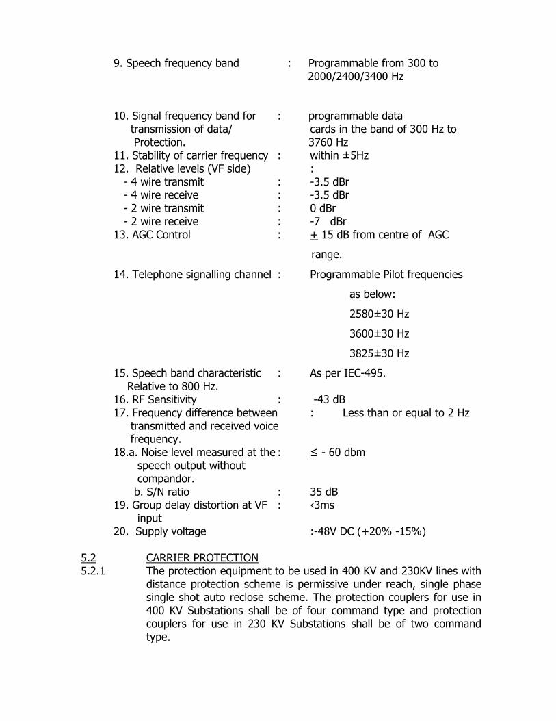
9. Speech frequency band : Programmable from 300 to 2000/2400/3400 Hz 10. Signal frequency band for : programmable data transmission of data/ cards in the band of 300 Hz to Protection. 3760 Hz 11. Stability of carrier frequency : within ±5Hz 12. Relative levels (VF side) : - 4 wire transmit : -3.5 dBr - 4 wire receive : -3.5 dBr - 2 wire transmit : 0 dBr - 2 wire receive : -7 dBr 13. AGC Control : + 15 dB from centre of AGC
range.
14. Telephone signalling channel : Programmable Pilot frequencies
as below:
2580±30 Hz
3600±30 Hz
3825±30 Hz
15. Speech band characteristic : As per IEC-495. Relative to 800 Hz. 16. RF Sensitivity : -43 dB 17. Frequency difference between : Less than or equal to 2 Hz transmitted and received voice frequency. 18.a. Noise level measured at the : ≤ - 60 dbm speech output without compandor. b. S/N ratio : 35 dB 19. Group delay distortion at VF : ‹3ms input 20. Supply voltage :-48V DC (+20% -15%)
5.2 CARRIER PROTECTION 5.2.1 The protection equipment to be used in 400 KV and 230KV lines with
distance protection scheme is permissive under reach, single phase single shot auto reclose scheme. The protection couplers for use in 400 KV Substations shall be of four command type and protection couplers for use in 230 KV Substations shall be of two command type.

5.2.2 The tenderers shall offer voice frequency transmission equipment for line protection signal. During transmission of line protection signals or when the fault has been located by the protective relays, speech channel in the carrier set and other unimportant superimposed signals shall be disconnected and the entire power of the carrier set will be made available for transmission of the line protection signals. The carrier protection channel should be provided in such a manner that the time interval that elapses between the instant the command is received from protection relays from the transmitting side and the time this command is passed on to the protection relays at the distant side shall not be more than 20 ms.
5.2.3 The carrier protection equipment shall be offered for transmission of
single or double protection depending on whether the H.T. line is single circuit or double circuit. The equipment offered for single circuit protection shall be flexible to be additionally equipped for double circuit protection, if necessary in future. The protection equipment shall be provided with inter connection unit suitable for connection to the protective relays. It should be possible to test the operational reliability of the protection channel over the carrier link. Suitable test print push buttons, lamps should be provided for this purpose. It should be possible to test the protection link from either of the two ends. During healthy conditions of the transmission line this test procedure must not initiate any tripping command.
5.2.4 However if a genuine trip signal is received during the testing process the test function should be completely blocked and over ridden i.e., trip signal must have absolute priority.
5.2.5 For better utilisation of VFT frequencies it shall be preferable if the speech channels and line protection signals are arranged in such a manner that the superimposed signalling frequency band is kept free for telemetering, and telefax etc.. In other words, the transmission of trip signal should take place within the speech band instead of superimposed signalling band and the dialling channel is used as guard channel. Bidders may offer equipment keeping the above in view.
5.2.6 The equipment offered should not be sensitive to corona noise,
which exists on high-tension lines and also should not be sensitive against impulse type of noise, which is created by operation of circuit breakers and isolators, spikes and electrical surges. Bidder shall explain clearly in their bid as to how their equipment has been rendered insensitive to corona noise and impulse type of noise. Both visual and audible alarm should be provided. To connect to external audible alarm two potential free relay contacts may be provided in the alarm circuit. Pilot frequency should be used as guard frequency of the protection unit.
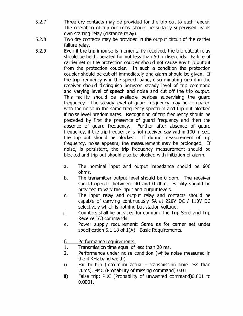
5.2.7 Three dry contacts may be provided for the trip out to each feeder. The operation of trip out relay should be suitably supervised by its own starting relay (distance relay).
5.2.8 Two dry contacts may be provided in the output circuit of the carrier failure relay.
5.2.9 Even if the trip impulse is momentarily received, the trip output relay should be held operated for not less than 50 milliseconds. Failure of carrier set or the protection coupler should not cause any trip output from the protection coupler. In such a condition the protection coupler should be cut off immediately and alarm should be given. If the trip frequency is in the speech band, discriminating circuit in the receiver should distinguish between steady level of trip command and varying level of speech and noise and cut off the trip output. This facility should be available besides supervising the guard frequency. The steady level of guard frequency may be compared with the noise in the same frequency spectrum and trip out blocked if noise level predominates. Recognition of trip frequency should be preceded by first the presence of guard frequency and then the absence of guard frequency. Further after absence of guard frequency, if the trip frequency is not received say within 100 m sec, the trip out should be blocked. If during measurement of trip frequency, noise appears, the measurement may be prolonged. If noise, is persistent, the trip frequency measurement should be blocked and trip out should also be blocked with initiation of alarm.
a. The nominal input and output impedance should be 600
ohms. b. The transmitter output level should be 0 dbm. The receiver
should operate between -40 and 0 dbm. Facility should be provided to vary the input and output levels.
c. The input relay and output relay and contacts should be capable of carrying continuously 5A at 220V DC / 110V DC selectively which is nothing but station voltage.
d. Counters shall be provided for counting the Trip Send and Trip Receive I/O commands.
e. Power supply requirement: Same as for carrier set under specification 5.1.18 of 1(A) - Basic Requirements.
f. Performance requirements: 1. Transmission time equal of less than 20 ms. 2. Performance under noise condition (white noise measured in
the 4 KHz band width). i) Fail to trip (maximum actual - transmission time less than
20ms). PMC (Probability of missing command) 0.01 ii) False trip: PUC (Probability of unwanted command)0.001 to
0.0001.
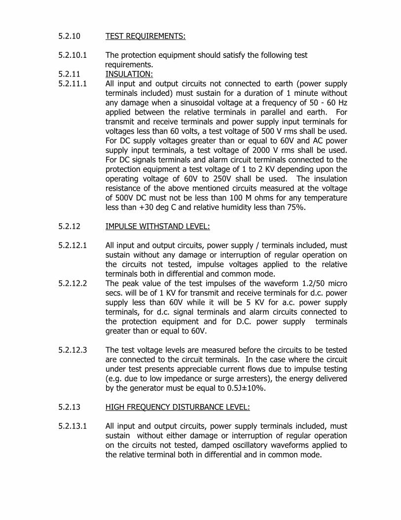
5.2.10 TEST REQUIREMENTS: 5.2.10.1 The protection equipment should satisfy the following test requirements. 5.2.11 INSULATION: 5.2.11.1 All input and output circuits not connected to earth (power supply
terminals included) must sustain for a duration of 1 minute without any damage when a sinusoidal voltage at a frequency of 50 - 60 Hz applied between the relative terminals in parallel and earth. For transmit and receive terminals and power supply input terminals for voltages less than 60 volts, a test voltage of 500 V rms shall be used. For DC supply voltages greater than or equal to 60V and AC power supply input terminals, a test voltage of 2000 V rms shall be used. For DC signals terminals and alarm circuit terminals connected to the protection equipment a test voltage of 1 to 2 KV depending upon the operating voltage of 60V to 250V shall be used. The insulation resistance of the above mentioned circuits measured at the voltage of 500V DC must not be less than 100 M ohms for any temperature less than +30 deg C and relative humidity less than 75%.
5.2.12 IMPULSE WITHSTAND LEVEL: 5.2.12.1 All input and output circuits, power supply / terminals included, must
sustain without any damage or interruption of regular operation on the circuits not tested, impulse voltages applied to the relative terminals both in differential and common mode.
5.2.12.2 The peak value of the test impulses of the waveform 1.2/50 micro secs. will be of 1 KV for transmit and receive terminals for d.c. power supply less than 60V while it will be 5 KV for a.c. power supply terminals, for d.c. signal terminals and alarm circuits connected to the protection equipment and for D.C. power supply terminals greater than or equal to 60V.
5.2.12.3 The test voltage levels are measured before the circuits to be tested
are connected to the circuit terminals. In the case where the circuit under test presents appreciable current flows due to impulse testing (e.g. due to low impedance or surge arresters), the energy delivered by the generator must be equal to 0.5J±10%.
5.2.13 HIGH FREQUENCY DISTURBANCE LEVEL: 5.2.13.1 All input and output circuits, power supply terminals included, must
sustain without either damage or interruption of regular operation on the circuits not tested, damped oscillatory waveforms applied to the relative terminal both in differential and in common mode.

5.2.13.2 The frequency of the wave form shall be 1 MHz with the envelope decaying to 50% of peak value at the end of three to six cycles. The repetition rate shall be 400 per second and the duration of the test shall be at least 2s.
5.2.13.3 The standard peak value of test voltage shall be 2.5KV for common
mode and 1KV for differential mode testing for DC signal terminals and alarm circuit terminals connected to the protection equipment and for DC power supply terminals for voltages greater than or equal to 60V and the AC power supply terminals respectively. It shall be 1.0 KV for common mode and 0.5 KV for differential mode in respect of transmit and receive terminals and DC power supply input terminals for voltages less than 60V.
5.2.14 SPECIFIC POWER SUPPLY REQUIREMENTS: 5.2.14.1 All teleprotection apparatus must sustain (without either any damage
of malfunctioning such as unwanted command) slow variations of the power supply voltage from nominal value to zero and zero to nominal value.
5.2.15 INTERRUPTIONS: 5.2.15.1 All teleprotection equipment shall sustain (without any malfunctioning such
as unwanted command) short interruptions in the power supply voltage not
longer than 20 ms, occurring in random sequence for a period not longer
than 20 ms. No command must occur if the power is switched off for a
longer time and then switched on.
5.2.16 REFLECTED NOISE:
If the teleprotection equipment is supplied from DC source, the noise measured across the power supply terminals of the equipment under test shall not be greater than either 3 mV psophometrically weighed or 10 mV peak to peak ( See CCITT recommendation P53 for psopho meter weighing coefficients.).
5.2.17 REVERSE POLARITY:
If the teleprotection equipment is supplied from a d.c. source reverse
polarity protection shall be provided to take care of any casual inversion of
power supply voltage.

5.2.18 DRAWINGS AND PAMPHLETS TO BE FURNISHED ALONG WITH THE TENDER:
Complete descriptive literature of carrier set and protection equipment. Full details and name of each modules in the above two equipments. Physical dimensional drawings of the equipment offered. Type tests and routine test reports of the equipment offered.
6.0 GUARANTEED PARTICULARS:
Unless full details are furnished, the tenders may not be considered. 7.0 TESTS: 7.1 TYPE TESTS (i) All the equipment offered shall be fully type tested as per the
relevant standards. The bids offering equipment not type tested as per the latest standards shall be rejected. These tests must not have been conducted earlier than five years from the date of bid opening. In case the equipment of the type and design offered, has already been type tested, the supplier shall furnish four sets of the type test reports along with the offer. In case these type tests are conducted earlier than five years, all the type tests as per relevant standards shall be carried out by the successful bidder in the presence of Purchasers representative free of cost.
(ii) The purchaser reserves the right to demand repetition of some or all
the type tests in the presence of his representatives. For this purpose, the supplier may quote unit rates for carrying out each type test and these charges will be considered for bid evaluation. For any change in the design / type already type tested and the design / type offered against this specification, the purchaser reserves the right to demand repetition of tests without any extra cost.
8.0 DOCUMENTATION
8.1 All drawings shall conform to relevant International Standards Organisation
(ISO) specification. All drawings shall be suitable for microfilming. All
dimensions and data shall be in S.I. units.
8.2 LIST OF DRAWINGS AND DOCUMENT:
The bidder shall furnish four sets of the followings along with his offer:

a) General outline and assembly drawings of the equipment. b) Graphs showing the performance of equipments in regard to
magnetisation characteristics. c) Schematic drawing e) Type test reports. f) Test reports, literature, pamphlets of the bought out item and
raw material. 8.3 The supplier shall within 2 weeks of placement of order, submit 4
sets of final versions of all the above drawings for purchaser's approval. The purchaser shall communicate his comments / approval on the drawings to the supplier within reasonable time. The supplier shall, if necessary modify the drawings and resubmit four copies of the modified drawings for purchaser's approval within two weeks from the date of receipt of purchaser's comments. After receipt of purchaser's approval the supplier shall within three weeks submit 20 prints and two good quality reproducibles of the approved drawings for purchaser's use.
8.4 Six sets of the type test report / standard test reports duly approved
by the purchaser shall be submitted by the supplier for distribution to field officers, before commencement of supply. Adequate copies of acceptance and routine test certificates, duly approved by the purchaser shall accompany the despatched consignment.
8.5 The manufacture of the equipment shall be strictly in accordance
with the approved drawings and no deviation shall be permitted without the written approval of the purchaser. All manufacturing and fabrication work in connection with the equipment prior to the approval of the drawing shall be at the supplier's risk.
8.6 Two copies of printed and bound volumes of operation, maintenance
and erection manuals in English language, for each type and rating of equipment supplied shall be sent by the supplier for each equipment. The manual shall contain all the drawings and information required for erection, operation and maintenance of the equipment to be supplied. The manual shall also contain a set of all the approved drawings, type test reports etc.,
9.0 INSTALLTION AND COMMISSIONING:
This enquiry is for supply only and the TANTRANSCO will arrange for installation, testing and commissioning. The tenders must furnish the details for installation and testing.
&&&&&

TECHNICAL GENERAL 1.0 TEST CERTIFICATE : 1.1 Test Certificates in triplicate for the materials furnishing the results of the
tests as per latest issue of ISS shall be forwarded and got approved before the materials are despatched. In addition to the tests called for in the specification the purchaser reserves the right of having such tests as he desires carried out at his own expenses to satisfy himself that the materials conform to the requirements of this specification. The materials may be rejected if the test results are not satisfactory. The type test certificates (photostat copies) as per latest ISS shall be furnished with the tender for reference and date of type test shall not be later than 5-years period. (Refer inspection clause 8 also for the details of inspection/ tests.)
COAXIAL CABLE TECHNICAL PARTICULARS COAXIAL CABLE -Sl.No. DESCRIPTION PARTICULARS 1. 2. 3. ---------------------------------------------------------------------------------------------------- 1. COAXIAL CABLE 1/1.22mm HF Coaxial Cable having annealed
plain tinned copper wire centre conductor, Semi-Air
spaced dielectric of composite helical
thread of polythene in a polythene tube and
annealed plain tinned copper wire braided,
Melinex tapped, extruded, special PVC sheathed,
black steel wire Braid armoured and characteristic
impedance of 75 ohms.
2. Centre Conductor Tinned copper wire of 1.22 mm dia.
3. Cable Core and Air : Centre Conductor wrapped with Spaced
Dielectric. polythylene string and extruded over with polythelene tube.
Radial thickness:1.00 mm. Diameter over Pe tube: 5.20 mm.
4. Outer Conductor Braid of tinned copper (Electrolytic grade/wire

of 0.20mm dia with 90% coverage.
5. Barrier PVC/MYLAR Tape.
6. Inner Jacket Special cable grade PVC Radial thickness 0.70 mm.
7. Bedding PVC Tape.
8. Armouring 0.4mm GI wire, 70% coverage.
9. Overall jacket PVC.
10. Electrical data:
a. Max Conductor resistance @ 20% 15.7 Ohms/KM b. Dielectric strength (Core to Shield) 4KV RMS for 1 minute c. Nominal Impedence 75 Ohm + 3 Ohms.
---------------------------------------------------------------------------------------------------- 1. 2. 3. --------------------------------------------------------------------------------------------------- d. Nominal capacitance 1 KHZ. 53 pf/meter e. Mx. Attenuator
frequency (KHZ) (KHZ) db/km 10 0.80 :
60 1.40 : 300 3.30 : 500 4.70 :
11. Min.Bending radius for installation 15 Cm 12. Packing Min.Continuous length. 500 Mtrs. + 5%. 13. Manufacturer's Embossing of Trade Mark/ identification. Manufacturer's name. Characteristic
impedance 75 Ohms Words "Tamil Nadu Electricity Board" in the outer sheath at 2 metre intervals.
----------------------------------------------------------------------------------------------------

TECHNICAL PARTICULARS MULTICORE CABLE 0.6 MM/4 PAIR/TELEPHONE CABLE 0.6 MM/1 PAIR 0.6mm dia. Annealed Tinned copper conductor, PVC insulated, colour coded, 2 cores twisted to form a pair, pairs laid up, Aluminium Mylar shielded with drain wire, melinex taped, over-all PVC sheathed, screened Telephone Cables conforming to I.T.D. Specification No.S/WS-113C. Four pair Single pair
1. Wire diameter : ............0.6mm ...............
2. Dia. Over Insulation : ............1.1mm ...............
3. Thickness of Insulation : ............0.25mm (Max.)........
4. Elongation.
a) Conductor : ..............15% ...............
b) Insulation : ............150% at break .......
c) Sheath : ............150% at break........
5. Tensile Strength.
a) Insulation : ........Min. 12.5 N/mm2
b) Sheath : ........Min. 12.5 N/mm2 ..........
6. Colour of pairs : As per Table-2 of I.T.D. Specification
S/WS-113C.
7. Laid up dia of pairs : 4.5mm 2.2mm
8. Mylar Tape : ...........13 micron ............
9. Polythene Aluminium tape : ...........25 micron ............
10. Drain wire : ...........7/0.15mm..............
11. Dia.Over shielded cable : 4.7mm 2.4mm
12. Overall diameter (Max.) : 6.3mm 3.5mm
13. Thickness of sheath (Min.) : 0.65mm 0.5mm
14. Colour of sheath : ...........Grey ................
15. Max. conductor resistance : ...........64.0 Ohms/KM ........at 20° C
16. Dielectric strength : 2KV rms at frequency of 50 HZ
between conductors.

17. Volume resistivity at 27° C : Min. 1x10¹³ Ohms/KM.
18. Capacitance unbalance : 250 P.F. Max.Per km.
19. Shrinkage Test : As per Clause VIII of IS:5831
20. Solder Test : As per clause 11.20 of I.T.D.
Specification S/WS-113C.
MANUFACTURER'S IDENTIFICATION: The manufacturers identification shall be provided throughout the length
of the cable and shall be by embossing the Trade Mark/Manufactureres name. In addition, the letters, "Tamil Nadu Electricity Board" should also be embossed in the outer sheath of the cable at two metre intervals.
TEST BEFORE DESPATCH
Each cable coil shall be subjected to the following tests: I. TELEPHONE CABLE: MECHANICAL:
PVC Outer Size (Overall) PVC Thickness Conduction Dia. with PVC Conductor above Dia. PVC Tape-Thickness over lap Presence of Rip card Presence of Drain Wire. ELECTRICAL: High voltage Test for 2 KV for 1 minute Insulation Resistance. Conductor Resistance. Capacitance unbalance. MECHANICAL PHYSICAL TEST: Conductor Elongation Insulation Elongation Tensile strength of PVC and sheath Shrinkage Test Solder Test
The purchaser reserves the right to inspect the cables and workmanship during the period of manufacture and to be present during the testing of the cables.

SECTION - 24
DETAILED TECHNICAL SPECIFICATION FOR PLCC
ELECTRONIC PRIVATE AUTOMATIC EXCHANGE (EPAX)
1.0 SCOPE: 1.1 This specification provides for design, manufacture, inspection and testing before despatch of EPAX Exchanges for Power Line Carrier Communication application and for use in conjunction with the existing carrier sets Type:ETL-41, Type:ETI-21, ETI-5 of M/s.ABB and Type 9505-V2, Type 9505-V3 and Type 6515 of M/s.BPL.
1.2 The EPAX exchanges for PLCC application shall conform in all respects to high standards of engineering design, workmanship with latest state of art technology and latest revisions of relevant standards at the time of offer and the purchaser shall have the power to reject any work (or) material, which in his judgement is not in full accordance therewith. The material used for manufacture of the equipment shall be of best class and capable of satisfactory operation in tropics with humid atmospheric condition without distortion (or) deterioration.
1.0. STANDARDS: 2.1 Unless otherwise specified elsewhere in the specification, the Power Line
Carrier Communication Indoor equipment along with accessories shall conform to the latest revisions and amendments thereof, of the following standards/Technical Particulars. Electronic Private : As specified under Technical
Automatic Exchange Particulars. (EPAX) for PLCC application.
2.2 Equipment meeting with the requirements of other authoritative International standards which ensure equal (or) better performance than the standards mentioned above, shall also be considered. When the equipment offered by the supplier conforms to other standards, salient points of difference between standards adopted and the standards in this specification shall be clearly brought out in the offer.
3.0. ELECTRONIC PRIVATE AUTOMATIC EXCHANGE(FOR PLCC APPLICATION):
3.1 The Electronic Private Automatic Exchanges shall work as local private automatic exchange. It should be fully micro-processor based system with pulse code modulation/time division multiplexing principle.
3.2 The Electronic Private Automatic Exchange should be compatible for operation with Electronic Switching Devices such as ESD-70 and ESLTRs at the farther end, having the common pulsing criteria as under.
a. Engage Pulse : 200 to 250 ms. ON
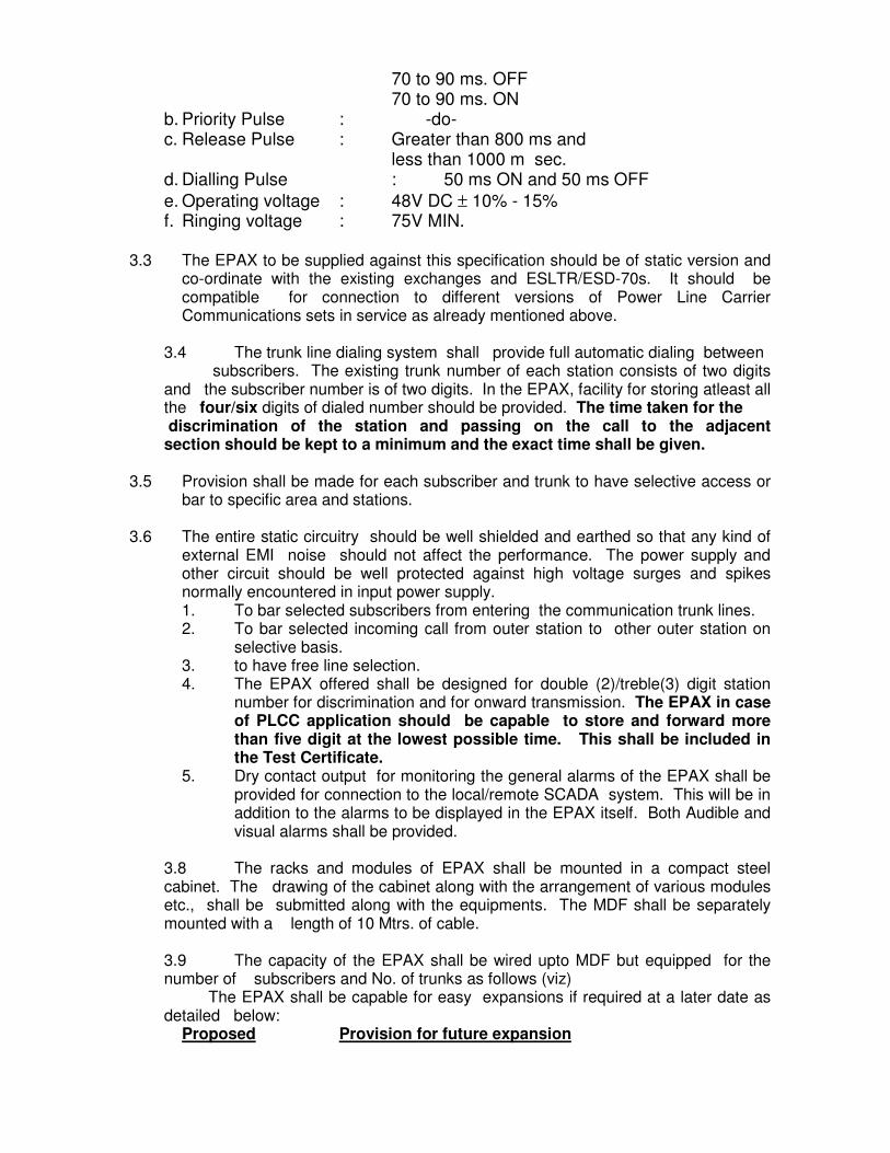
70 to 90 ms. OFF 70 to 90 ms. ON b. Priority Pulse : -do- c. Release Pulse : Greater than 800 ms and
less than 1000 m sec. d. Dialling Pulse : 50 ms ON and 50 ms OFF
e. Operating voltage : 48V DC ± 10% - 15% f. Ringing voltage : 75V MIN.
3.3 The EPAX to be supplied against this specification should be of static version and co-ordinate with the existing exchanges and ESLTR/ESD-70s. It should be compatible for connection to different versions of Power Line Carrier Communications sets in service as already mentioned above.
3.4 The trunk line dialing system shall provide full automatic dialing between subscribers. The existing trunk number of each station consists of two digits and the subscriber number is of two digits. In the EPAX, facility for storing atleast all the four/six digits of dialed number should be provided. The time taken for the discrimination of the station and passing on the call to the adjacent section should be kept to a minimum and the exact time shall be given.
3.5 Provision shall be made for each subscriber and trunk to have selective access or bar to specific area and stations.
3.6 The entire static circuitry should be well shielded and earthed so that any kind of
external EMI noise should not affect the performance. The power supply and other circuit should be well protected against high voltage surges and spikes normally encountered in input power supply. 1. To bar selected subscribers from entering the communication trunk lines. 2. To bar selected incoming call from outer station to other outer station on
selective basis. 3. to have free line selection. 4. The EPAX offered shall be designed for double (2)/treble(3) digit station
number for discrimination and for onward transmission. The EPAX in case of PLCC application should be capable to store and forward more than five digit at the lowest possible time. This shall be included in the Test Certificate.
5. Dry contact output for monitoring the general alarms of the EPAX shall be provided for connection to the local/remote SCADA system. This will be in addition to the alarms to be displayed in the EPAX itself. Both Audible and visual alarms shall be provided.
3.8 The racks and modules of EPAX shall be mounted in a compact steel cabinet. The drawing of the cabinet along with the arrangement of various modules etc., shall be submitted along with the equipments. The MDF shall be separately mounted with a length of 10 Mtrs. of cable.
3.9 The capacity of the EPAX shall be wired upto MDF but equipped for the number of subscribers and No. of trunks as follows (viz)
The EPAX shall be capable for easy expansions if required at a later date as detailed below:
Proposed Provision for future expansion
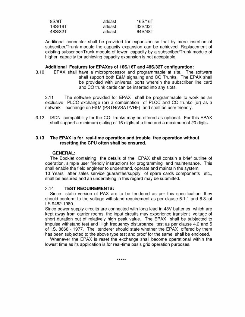
8S/8T atleast 16S/16T 16S/16T atleast 32S/32T 48S/32T atleast 64S/48T
Additional connector shall be provided for expansion so that by mere insertion of subscriber/Trunk module the capacity expansion can be achieved. Replacement of existing subscriber/Trunk module of lower capacity by a subscriber/Trunk module of higher capacity for achieving capacity expansion is not acceptable. Additional Features for EPAXes of 16S/16T and 48S/32T configuration:
3.10 EPAX shall have a microprocessor and programmable at site. The software shall support both E&M signaling and CO Trunks. The EPAX shall be provided with universal ports wherein the subscriber line card and CO trunk cards can be inserted into any slots.
3.11 The software provided for EPAX shall be programmable to work as an exclusive PLCC exchange (or) a combination of PLCC and CO trunks (or) as a network exchange on E&M (PSTN/VSAT/VHF) and shall be user friendly.
3.12 ISDN compatibility for the CO trunks may be offered as optional. For this EPAX shall support a minimum dialing of 16 digits at a time and a maximum of 20 digits.
3.13 The EPAX is for real-time operation and trouble free operation without resetting the CPU often shall be ensured.
GENERAL:
The Booklet containing the details of the EPAX shall contain a brief outline of operation, simple user friendly instructions for programming and maintenance. This shall enable the field engineer to understand, operate and maintain the system. 10 Years after sales service guarantee/supply of spare cards components etc., shall be assured and an undertaking in this regard may be submitted. 3.14 TEST REQUIREMENTS:
Since static version of PAX are to be tendered as per this specification, they should conform to the voltage withstand requirement as per clause 6.1.1 and 6.3. of I.S.9482-1980. Since power supply circuits are connected with long lead in 48V batteries which are kept away from carrier rooms, the input circuits may experience transient voltage of short duration but of relatively high peak value. The EPAX shall be subjected to impulse withstand test and High frequency disturbance test as per clause 4.2 and 5 of I.S. 8666 - 1977. The tenderer should state whether the EPAX offered by them has been subjected to the above type test and proof for the same shall be enclosed. Whenever the EPAX is reset the exchange shall become operational within the lowest time as its application is for real-time basis grid operation purposes.
*****

TECHNICAL DATA OF EPAX 1. Subscriber lines : Wired for Maximum capacity
2. Trunk lines : Wired for Maximum capacity
3. Switching Network : 256 Port for Non-blocking switch.
4. Numbering scheme : Flexible numbering scheme.
5. Switching Technique : Digital Type (Details shall be given)
6. Max. loop resistance : 1200 ohm for subscriber lines 2400 ohm for Trunk lines. 7. Insertion loss : 4 db for line to line at 800 HZ. 0.5 db for trunk to line at 800 HZ. 8. Frequency Response : 300 Hz to 3400 Hz.
9. Cross Talk : More than 70 DB between 300 to 3400Hz
10. Ringing Local ring : 1500 MS On/1500 MS Off. Trunk ring : 400 MS On/200 MS Off. 400 MS On/2000 MS Off. Ring back tone : 500 MS On/500 MS Off. 11. Tones Local ring : 1500 MS On/1500 MS Off. Trunk ring : 400 MS On/200 MS Off. 400 MS On/2000 MS Off. Call back ring : 500 MS On/500 MS Off. 12. Alarms : Card level fault visual display and audible alarm. 13. Display : Line status. System status. Power Supply. Faulty trunks. Time. 14. Line Protection : Line fuse and surge protection on each subscriber line. 15. MDF : To be mounted separately with a length of 10 Mtrs. Cable. 16. Operating Power supply : DC 48V (+) 10% & (-) 15% 17. The Exchange if needed in future shall support Load Despatch feature and
the subscribers at the remote end provided with a remote extension interface (RE I) through which the remote subscriber can be given eight dialing or lift and talk facility through the Exchange at Load Despatch Centre.
18. The Exchange also shall provision of operator consoles for use in future.
*/*/*

Tamil Nadu Transmission Corporation Limited Bharat Heavy Electricals Limited 400/110 KV Substation at Thappagundu & 400/230‐110 KV Substation at Anikadavu
Page 1 of 14
SECTION – 3
GENERAL TECHNICAL REQUIREMENTS 3.0 Foreword
The provision under this section is intended to supplement general requirements for the materials, equipment and services covered under other sections.
3.1 PROJECT INFORMATION AND SYSTEM PARAMETERS a) Customer : M/s Tamil Nadu Transmission Corporation Limited
b) Project Title : 400/110 KV Substation at Thappagundu & 400/230/110 KV Substation at Anikadavu
c) Transport facilities : Road/Rail d) Site location : THAPPAGUNDU IN THENI DISTRICT, MADURAI REGION & ANIKADAVU IN TIRUPPUR DISTRICT, COIMBATORE REGION
The following system parameters shall prevail:
Nominal system voltage
400 kV 230kV 110 kV
Highest system voltage 420 kV 245kV 132 kV Frequency 50 Hz 50 Hz 50 Hz Minimum creepage 25mm/kV 25mm/kV 25mm/kV System Earthing Effectively
Earthed Effectively Earthed
Effectively Earthed
SITE CONDITIONS 3.1.1 Ambient Temperature
a) Ambient air temp. (max.) : 50 deg C B) Max Temp. for design : : 50 deg C b) Ambient air temp. (min.) : 20 deg C c) Max, Daily average ambient air temp. : 45 deg C d) Max. yearly average ambient air temp. : 32 deg C
3.1.2 Max. humidity : 100% Max. 3.1.3 Average thunder storm days per annum : 50 3.1.4 Average rainy days per annum : 90 3.1.5 Average Annual rainfall : 1000 mm
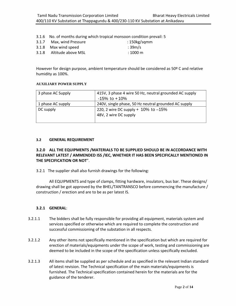
Tamil Nadu Transmission Corporation Limited Bharat Heavy Electricals Limited 400/110 KV Substation at Thappagundu & 400/230‐110 KV Substation at Anikadavu
Page 2 of 14
3.1.6 No. of months during which tropical monsoon condition prevail: 5 3.1.7 Max, wind Pressure : 150kg/sqmm 3.1.8 Max wind speed : 39m/s 3.1.8 Altitude above MSL : 1000 m However for design purpose, ambient temperature should be considered as 50º C and relative humidity as 100%. AUXILIARY POWER SUPPLY 3 phase AC Supply 415V, 3 phase 4 wire 50 Hz, neutral grounded AC supply
-15% to +10%1 phase AC supply 240V, single phase, 50 Hz neutral grounded AC supplyDC supply 220, 2 wire DC supply + 10% to –15%
48V, 2 wire DC supply
3.2 GENERAL REQUIREMENT 3.2.0 ALL THE EQUIPMENTS /MATERIALS TO BE SUPPLIED SHOULD BE IN ACCORDANCE WITH RELEVANT LATEST / AMMENDED ISS /IEC, WHETHER IT HAS BEEN SPECIFICALLY MENTIONED IN THE SPECIFICATION OR NOT”.
3.2.1 The supplier shall also furnish drawings for the following:
All EQUIPMENTS and type of clamps, fitting hardware, insulators, bus bar. These designs/ drawing shall be got approved by the BHEL/TANTRANSCO before commencing the manufacture / construction / erection and are to be as per latest IS. 3.2.1 GENERAL:
3.2.1.1 The bidders shall be fully responsible for providing all equipment, materials system and services specified or otherwise which are required to complete the construction and successful commissioning of the substation in all respects.
3.2.1.2 Any other items not specifically mentioned in the specification but which are required for
erection of materials/equipments under the scope of work, testing and commissioning are deemed to be included in the scope of the specification unless specifically excluded.
3.2.1.3 All items shall be supplied as per schedule and as specified in the relevant Indian standard of latest revision. The Technical specification of the main materials/equipments is furnished. The Technical specification contained herein for the materials are for the guidance of the tenderer.

Tamil Nadu Transmission Corporation Limited Bharat Heavy Electricals Limited 400/110 KV Substation at Thappagundu & 400/230‐110 KV Substation at Anikadavu
Page 3 of 14
3.2.1.4 The Tenderers are requested to procure the equipments/materials/component only from
reputed /qualified manufacturer as per Technical requirement stipulated in Section ‐ I of Technical specifications. Approval of make of item shall be taken up by vendor from TANTRANSCO himself.
3.3 SPECIFIC REQUIREMENT
3.3.1 The Supplier shall furnish make/manufacturer, catalogues, engineering data, and technical
information, design documents, drawings etc., fully in conformity with the technical specification and get approval from competent authority before commencement of any work.
3.3.2 All steel materials, other than materials for earthing should be of galvanized if not
specified.
3.4 SPECIFIC TECHNICAL REQUIREMENTS: / Drawing submission The successful bidder shall submit all drawings and documents as per clause no. 3.29 along with the list of drawings within 7 days after placement of order to BHEL.
3.5 STANDARD:
The goods supplied under this contract shall conform to the standards mentioned in the Technical Specifications and when no applicable standard is mentioned, to the standard specified by the Institution of Central / State Government or internationally recognized Institutions shall be applicable and such standards shall be the latest issued by the concerned institution.
3.6 TEST CERTIFICATE: Copies of all test certificates relating to material to be procured by the Supplier for the works shall be forwarded to BHEL.
3.7 Inspection clause :
3.7.1 The BHEL/TANTRANSCO or his representative shall have the right to inspect and/or test
the goods /works to confirm their conformity to the supplier. BHEL/TANTRANSCO shall notify the supplier in writing of the identity of any representatives authorized for these purposes. The inspections and tests may be conducted on the premises of the supplier or his Sub vendor at the point of delivery and /or at the goods’ final destination. Where tests are conducted in the premises of Supplier, all reasonable facility and assistance including access to drawings and production data shall be furnished at no charge to the BHEL.

Tamil Nadu Transmission Corporation Limited Bharat Heavy Electricals Limited 400/110 KV Substation at Thappagundu & 400/230‐110 KV Substation at Anikadavu
Page 4 of 14
Should any inspected or tested goods fail to conform to specifications, the BHEL/TANTRANSCO may reject them and the supplier shall either replace the rejected goods or make all alterations necessary to meet specification requirements free of cost to the BHEL/TANTRANSCO within one week of intimation. The BHEL/TANTRANSCO’s right to inspect, test and where necessary reject the goods after the goods; arrival at the site, shall in no way be limited or waived by reason of the goods having been previously inspected. Tested and passed by the BHEL/TANTRANSCO or his representative prior to the goods dispatch.
3.7.2 Not less than 15 (Fifteen) days advance intimation shall be given about the quantity of materials that will be ready for inspection by the officers of TANTRANSCO/ BHEL/Third agency authorized by the Corporation. The materials should not be dispatched without instruction from the Corporation.
3.8 GUARANTEE:
3.8.1 The supplier shall guarantee that the goods under the Contract are new, unused of the most recent or current models and incorporated all recent improvements in design and materials unless provided otherwise in the Contract. The supplier shall further guarantee that the goods supplied under this Contract shall have no defects arising from design, materials or workmanship, installation and erection, if that may develop under normal use of the supplied goods. The supplier shall also guarantee the performance of the works executed by him including the performance of all the materials/goods supplied by him.
3.8.2 BHEL shall promptly notify supplier in writing of any claims arising under guarantee in
respect of goods. Upon receipt of such notice, the supplier shall, with all reasonable speed, repair or replace the defective works or parts thereof, free of cost at site. All the expenses towards transportation of defective parts to supplier’s works and of repaired/replaced parts to site shall be borne by the Supplier.
3.8.3 If the Supplier, having been notified, fails to remedy the defects within 14 days, the BHEL will proceed to take such remedial action as may be necessary, at the supplier’s risk and expenses. All expenses in this regard will be recovered from Supplier.
3.9 PRE COMMISSIONING TESTING :( if applicable) On completion of erection of equipments and before charging each item of equipments shall be thoroughly cleaned and inspected jointly by the TANTRANSCO and the BHEL for correctness and completeness of installation and acceptability for charging leading to initial pre commissioning test. The pre commissioning testing to be carried all equipments in the presence of Board Engineers. Necessary tools, testing kits are to be arranged by the Supplier.

Tamil Nadu Transmission Corporation Limited Bharat Heavy Electricals Limited 400/110 KV Substation at Thappagundu & 400/230‐110 KV Substation at Anikadavu
Page 5 of 14
3.10 PACKING:
3.10.1 The supplier shall provide such packing of the goods as is required to prevent their
damage or deterioration during transit to their final destination as indicated in the Contract. The packing shall be sufficient to withstand, without limitation, rough handling during transit to their final destination as indicated in the Contract and exposure to extreme temperatures, salt and precipitation etc., during transport and open storage. Packing case size and weights shall be taken into consideration wherever appropriate, the remoteness of the ‘goods’ final destination and absence of heavy mechanized handling facilities, at all points in transit.
3.10.2 The packing, marking and documentation within and outside the package shall comply
strictly with such special requirements as shall be expressly provided for in the Contract or in any subsequent instructions issued by BHEL.
3.11 COLOUR SCHEME AND CODES FOR PIPE SERVICE/PANELS The supplier shall propose a color scheme for those equipment/Items for which the colour scheme has not been specified in the specification for the approval of BHEL/TANTRANSCO. The decision of BHEL/TANTRANSCO shall be final. The scheme shall include:
Finishing colour of Indoor equipment
Finishing colour of Outdoor equipment.
Finish colour of all cubicles. Finishing colour of various auxiliary system equipment including piping
Finishing colour of various building items. All the steel works shall be thoroughly cleaned of rust , scale , oil , grease, dirt and scarf by pickling , emulsion cleaning , etc. The sheet steel shall be phosphated /oven dried and then painted with two coats of zinc rich primer paints . After application of the primer, two coats of finished synthetic enamel paint shall be applied. The colour of the finished coats inside shall be glossy white and exterior of the treated sheet steel shall be shade 631 of IS 5 /RAL 7032 for all switchboard /MCC/distribution board , control panels etc. Sufficient quantities of touch paint shall be furnished for application at site. All the indoor cubicles shall be the same as exterior surface and for other miscellaneous items, colour scheme will be approved by the BHEL/TANTRANSCO.
3.12 SURFACE FINISH
All interiors and exteriors of tanks, control cubicles and other metal parts shall be thoroughly cleaned to remove all rust, scales, corrosion, greases or other adhering foreign matter. All steel surfaces in contact with insulating oil as far as accessible, shall be painted with not less than two coats of heat resistant, oil insoluble, insulating paints.

Tamil Nadu Transmission Corporation Limited Bharat Heavy Electricals Limited 400/110 KV Substation at Thappagundu & 400/230‐110 KV Substation at Anikadavu
Page 6 of 14
All metal surfaces exposed to atmosphere shall be given two primer coats of zinc chromate and two coats of epoxy paint with epoxy base thinner. All metal parts not accessible for painting shall be made of corrosion resisting material. All machine finished or bright surfaces shall be coated with a suitable preventive compound and suitably wrapped or otherwise protected. All paints shall be carefully selected to withstand tropical heat and extremes of weather within the limit specified. The paint shall not scale off or wrinkle or be removed by abrasion due to normal handling.
3.13 PROTECTION
All coated surfaces shall be protected against abrasion, impact, discoloration and any other damages. All exposed threaded portions shall be suitably protected with either a metallic or a non‐metallic protecting device. All ends of all valves, pipings and conduit equipment connections shall be properly sealed with suitable devices to protect them from damage.
All equipment accessories and wiring shall have fungus protection, involving special treatment of insulation and metal against fungus, insects and corrosion. The parts which are likely to get rusted, due to exposure to weather should also be properly treated and protected in a suitable manner. Screens of corrosion resistant material shall be furnished on all ventilating louvers to prevent entry of insects.
3.14 FUNGI‐STATIC VARNISH
Besides the space heaters, special moisture and fungus resistant varnish shall be applied on the parts, which may be subjected or predisposed to the formation of fungi due to the presence or deposit of nutrient substances. The varnish shall not be applied to any surface of part where the treatment will interface with the operation or performance of the equipment. Such surfaces or parts shall be protected against the application to the varnish.
3.15 GALVANIZING
All nuts and pins shall be adequately locked. Nuts, bolts and pins used inside the transformer and tap‐changer compartment where gaskets are not used shall be provided with spring washers or locknuts. Where galvanizing is specified, it shall be applied by the hot dipped process or by electro‐galvanizing process and for all parts, other than steel wires, shall consist of a thickness of zinc coating equivalent to not less than 610 gm of zinc per square metre of surface.The zinc coating shall be smooth, of uniform thickness and free from defects.
3.16 DEGREE OF PROTECTION
The supplier shall propose following Degree of protection for those equipment/Items for which the degree of protection has not been specified in the specification for the approval of BHEL/TANTRANSCO. The decision of BHEL/TANTRANSCO shall be final. The enclosures of the Control Cabinets, Junction boxes and Marshalling boxes panels etc to be installed shall be provided with degree of protection as detailed here under: a) Installed outdoor: IP‐55

Tamil Nadu Transmission Corporation Limited Bharat Heavy Electricals Limited 400/110 KV Substation at Thappagundu & 400/230‐110 KV Substation at Anikadavu
Page 7 of 14
b) Installed indoor in air conditioned area: IP‐42 c ) Installed in covered area IP:52 d) For LT switchgear (AC & DC distribution Boards): IP‐54 The degree of protection shall be in accordance with IS:13947, ( Part‐1)/IEC‐947(Part‐1). Type test report/or degree of protection test on each type of the box shall be submitted for approval.
3.17 RATING PLATES, NAME PLATES AND LABELS
Type or serial number together with details of the loading conditions under which the item of the substation in question has designed to operate and such diagram plates as may be required by the BHEL/TANTRANSCO. The rating plate for each equipment shall be according to IEC requirements.
Alternately two separate plates one with Hindi and other with English inscriptions may be provided.
During approvals drawings of Rating/name plates/lables shall also be submitted.
3.18 EARTHING
Circuit breakers, LA, Isolator, CVT, CT, BPI shall be provided with two grounding pads suitable for connection to galvanized steel flat. Control panels, Relay panel, outdoor marshalling boxes, Junction boxes, Lighting panels and distribution board shall be provided with two grounding pads, for connection to galvanized steel flat. The two pads shall be provided, one each at the middle of the two opposite sides of the bottom frame of the equipment. Earthing of hinged door shall be done by using a separate earth wire.
3.19 TERMINAL BLOCKS AND WIRING
Control and instrument leads from the switchboards or from other equipment will be brought to terminal boxes or control cabinets in conduits. All Inter‐phase and external connections to equipment or to control cubicles will be made through terminal blocks.
Terminal blocks shall be 1100 V grade and have continuous rating to carry the maximum expected current on the terminals. Those shall be of moulded piece complete with insulated barriers stud type terminals, washers, nuts and lock nuts. Screw clamp, overall insulated, insertion type, rail mounted terminals can be used in place of stud type terminals. But preferably the terminal blocks shall be non‐disconnecting stud type equivalent to Elmex type CATM4, Phoenix cage clamp type of Wedge or equivalent. The Insulating material of terminal block shall be nylon 6.6 which shall be free of halogens, fluorocarbons etc.
Terminal block for current transformer and voltage transformer secondary leads shall be provided with test links and isolating facilities. The current transformer secondary leads shall also be provided with short circuiting and earthing facilities.

Tamil Nadu Transmission Corporation Limited Bharat Heavy Electricals Limited 400/110 KV Substation at Thappagundu & 400/230‐110 KV Substation at Anikadavu
Page 8 of 14
The terminal shall be that maximum contact area is achieved when a cable is terminated. The terminal shall have a locking characteristic to prevent cable from escaping from the terminal clamp unless it is done intentionally. The conducting part in contact with cable shall preferably be tinned or silver plated however Nickel plated copper or zinc plated steel shall also be acceptable. The terminal blocks shall be of extensible design. The terminal blocks shall have locking arrangement to prevent its escape from the mounting rails.
The terminal blocks shall be fully enclosed with removable covers of transparent, non deteriorating type plastic material. Insulating barriers shall be provided between the terminal blocks. These barriers shall not hinder the operator from carrying out the wiring without removing the barriers.
Unless otherwise specified terminal blocks shall be suitable for connecting the following conductors on each side.
All circuits except CT circuits : Minimum of 2 nos. of 2.5 sq.mm,copper flexible.
All CT circuits : Minimum of 4 nos. of 2.5 sq.mm, copper flexible..
The arrangements shall be in such a manner so that it is possible to safely connect or disconnect terminals on live circuits and replace fuse links when the cabinet is live. At least 20 % spare terminals shall be provided on each panel/cubicle/box and these spare terminals shall be uniformly distributed on all terminals rows.
There shall be a minimum clearance of 250mm between the first bottom row of terminal block and the associated cable gland plate. Also the clearance between two rows of terminal blocks shall be a minimum of 150 mm. The Supplier shall furnish all wire, conduits and terminals for the necessary inter‐phase electrical connection (where applicable) as well as between phases and common terminal boxes or control cabinets.
All input and output terminals of each control cubicle shall be tested for surge withstand capability in accordance with the relevant IEC Publications, in both longitudinal and transverse modes. The supplier shall also provide all necessary filtering, surge protection, interface relays and any other measures necessary to achieve an impulse withstand level at the cable interfaces of the equipment.
TB sizes for incoming power supply shall be informed/confirmed during drwawing approval stage.
TBs should be suitable for cable sizes all cable sizes.
3.20 CONTROL CABINETS, JUNCTION BOXES, TERMINALS BOXES AND MARSHALLING BOXES FOR OUTDOOR EQUIPMENTS
All types of boxes, cabinets etc. shall generally conform to and be tested in accordance with IS‐5039, IS‐8623 or IEC‐439, as applicable and the clause given below.

Tamil Nadu Transmission Corporation Limited Bharat Heavy Electricals Limited 400/110 KV Substation at Thappagundu & 400/230‐110 KV Substation at Anikadavu
Page 9 of 14
Control cabinet, Junction boxes, Marshalling boxes & Terminal boxes shall be made of sheet steel. Sheet steel used shall be at least 3.0 mm thick cold rolled or 3 mm hot rolled. The box shall be properly braced to prevent wobbling. There shall be sufficient reinforcement to provide level surfaces, resistance to vibrations and rigidity during transportation and installation. Cabinet/boxes shall be free standing floor mounting type, wall mounting type or pedestal mounting type as per requirements.
Cabinet /boxes shall be provided with double hinged doors with padlocking arrangements. The distance between two hinges shall be adequate to ensure uniform sealing pressure against atmosphere. The quality of gaskets shall be such that it does not get damaged/cracked during the operation of the equipment.
All door, removable covers and plates shall be gasketed all around with suitably profiled Neoprene gaskets. The gasket shall be tested in accordance with approved quality plan. The quality of gasket shall be such that it does not get damaged /cracked during the years of the equipment or its major overhaul whichever is earlier. All gasketed surfaces shall be smooth, straight and reinforced if necessary to minimize distortion and to make a tight seal. Ventilating Louvers, if provided, shall have screen and filters. The screen shall be fine wire mesh made of brass.
All boxes/cabinets shall be designed for the entry of cables from bottom by means of weather proof and dust‐proof connections. Boxes and cabinets shall be designed with generous clearances to avoid interference between the wiring entering from below and any terminal blocks or accessories mounted within the box or cabinet. Suitable cable gland plate projecting atleast 150 mm above from the base of the Marshalling Kiosk/box shall be provided for this purpose along with the proper blanking plates. Necessary number of cable glands shall be supplied and fitted on this gland. The gland shall project atleast 25mm above gland plate to prevent entry of moisture in cable crutch. Gland plate shall have provision for some future glands to be provided later, if required
3.21 SPACE HEATERS
The heater shall be suitable for continuous operation at 240 V AC supply voltage and shall be provided with on – off switch and fuse shall be provided for heater.
One or more adequately rated, thermostatically connected heaters shall be supplied to prevent condensation in any compartment.
3.22 DELIVERY OF GOODS AND DOCUMENTS RELATED THERETO:
Delivery of goods shall be made by the supplier in accordance with the terms specified by the BHEL in its schedule of requirements.
3.23 INCIDENTAL SERVICES: The Supplier is required to provide any or all the services broadly outlined in the Technical specification. Any other minor incidental service related to the scope of work like providing necessary assistance whether specifically mentioned or not must be carried out by the

Tamil Nadu Transmission Corporation Limited Bharat Heavy Electricals Limited 400/110 KV Substation at Thappagundu & 400/230‐110 KV Substation at Anikadavu
Page 10 of 14
Supplier at his own cost. All tools, Tackles Plant etc., required for completion of above works shall be brought by the Supplier.
3.24 DISCREPANCIES BETWEEN DRAWING AND SPECIFICATION:
Should there be any discrepancy between the specifications and/or schedule of prices and/or drawings or any inconsistency, error or omission in either of them, reference must be made to the BHEL/TANTRANSCO for an explanation and the Supplier will be held responsible for any errors that may occur in the work through neglect of this precaution. The explanation of the BHEL/TANTRANSCO shall be final and binding on the Supplier. 3.25 APPROVAL PROCEDURE
The scheduled dates for the submission of drawings as well as for, any data/information to be furnished by the Employer would be as per the following schedule. The supplier shall also submit required no. of copies as mentioned in this specification of all drawings/design documents/test reports for approval by the Employer. The following schedule shall be followed generally for approval.
i. First Submission 7 days after LOI/PO
ii. Approval/comments/by employer on Initial submission
Reasonable time
iii. Resubmission Within 7 days (whenever from date of comments required) Including both ways postal time.
iv. Approval or comments Within 2 weeks of receipt of resubmission.
v. Furnishing of distribution copies
2 weeks from the date of last approval.
Note: The supplier may please note that all resubmissions must incorporate, all comments given in the submission by the Employer failing which the submission of documents is likely to be returned. Every revision shall be a revision number, date and subject, in a revision block provided in the drawing, clearly marking the changes incorporated.
The title block of drawings shall contain the following information incorporated in all contract drawings. Please refer enclosed sheet for details of Title block.
3.26 TITLE BLOCK Following Title Blocks to be used in drawings at the time of drawing approvals For Thappagundu
Customer M/s Tamil Nadu Transmission Corporation Limited

Tamil Nadu Transmission Corporation Limited Bharat Heavy Electricals Limited 400/110 KV Substation at Thappagundu & 400/230‐110 KV Substation at Anikadavu
Page 11 of 14
Project: 400/110 KV Substation at Thappagundu
Contractor BHEL
For Anikadavu
Customer M/s Tamil Nadu Transmission Corporation Limited
Project: 400/230‐110 KV Substation at Anikadavu
Contractor BHEL
3.27 DOCUMENTS TO BE SUBMITTED ALONGWITH OFFER
1) Drawings 2) Guaranteed Technical Particulars 3) Type Test Reports 4) List of Part Supplies with rating
Drawings & Documents submitted at the time of offer shall be subject to review at contract stage. 3.28 DOCUMENTATION SCHEDULE
Following Documentation schedule to be followed per project.
S. No.
DESCRIPTION TENDER STAGE
CONTRACT STAGE FOR APPROVAL
FINAL DOCUMENTATION
Prints Prints CDs 1 Drawings and Data Sheets 1 7 10 5
2 Drawings “As Built “ ‐ ‐ 10 3 Type Test Reports 1 7 10 4 Erection Manuals ‐ 7 10 5 Operation and Maintenance
Manuals ‐ 7 10
6 Manufacturing Quality Plan ‐ 7 10
7 Field Quality Plan ‐ 7 10
8 Inspection Test Reports ‐ 7 10
Note: Drawings will also be submitted in CD/DVD in Latest AUTOCAD‐2004 or Later version or any other CAD package along with conversion files for all major items.
Tamil Nadu Transmission Corporation Limited Bharat Heavy Electricals Limited 400/110 KV Substation at Thappagundu & 400/230‐110 KV Substation at Anikadavu
Page 12 of 14
Final Documentation shall be submitted in bound volumes with details of Customer & Project etc. written on top.

Tamil Nadu Transmission Corporation Limited Bharat Heavy Electricals Limited 400/110 KV Substation at Thappagundu & 400/230‐110 KV Substation at Anikadavu
Page 13 of 14
APPENDIX-A
SCHEDULE OF TECHNICAL DEVIATION
The following are the deviations/variations/exceptions from the specification:
SECTION CLAUSE NO. / PAGE NO. STATEMENT OF DEVIATION / VARIATIONS / EXCEPTIONS
In case, this schedule is not submitted, it will be presumed that the equipment /material to be supplied under this contract is deemed to be in compliance with the specification.
If there is NIL deviation, even then the format to be filled as NIL DEVIATION
Note: Continuation sheets of like size and format may be used as per the Bidder’s Requirement and shall be annexed to this schedule.
Place Signature of the authorized representative of
Date Bidder’s name …………………………………………….
Designation …………………………………………….
Company seal …………………………………………….

Tamil Nadu Transmission Corporation Limited Bharat Heavy Electricals Limited 400/110 KV Substation at Thappagundu & 400/230‐110 KV Substation at Anikadavu
Page 14 of 14
APPENDIX-B
BIDDER’S UNDERTAKING FOR TYPE TEST REPORTS
Bidder shall take type test report, MQP, and drawing approval from TANTRANSCO without any commercial / delivery implication to BHEL. In case type test reports are not acceptable to customer due to any technical reason, the same shall be conducted free of cost.
Place Signature of the authorized representative of
Bidder ‘name-------------------------------------
Date
Designation----------------------------------------
Company seal -------------------------------------

Tamil Nadu Transmission Corporation Limited Bharat Heavy Electricals Limited 400/110 KV S/STN at Thappagundu & 400/230‐110 KV S/STN at Anikadavu TB‐363‐510‐013 Technical specification for Power Line Carrier Communication Rev No. 00
Page 1 of 1
SECTION – 4
GUARANTEED TECHNICAL PARTICULARS
Please fill in the GTP of various equipments of PLCC package enclosed here in

COUPLING DEVICE (PHASE TO PHASE COUPLING) LINE MATCHINE UNIT: SL.NO. DESCRIPTION PARTICULARS 1. Name of the manufacturer and country of origin. 2. Type. 3. Whether impedance transformer has been provided. 4. Matching impedance to HT line. 5. Matching impedance to co-axial cable. 6. Characteristic impedance. 7. Turns ratio of impedance matching transformer. 8. Attenuation at transmission ranges at rated burden. 9. Operating attenuation. 10. Test voltage of transformer (1 Min). 11. Test voltage of capacitor (1 Min). 12. Rated current at carrier frequencies. 13. Rated voltage at carrier frequencies. 14. Range of capacitance of the coupling capacitor to which the line matching unit is available. 15. a. Frequency response of the unit. b. Whether the frequency response is flat. (Please enclose a graph) 16. Details of the mounting of the unit may be submitted. 17. Whether impedance matching units have provisions for matching either phase to phase or phase to ground coupling. 18. Whether 3 position switch has been provided for change over to phase ground coupling. 19. No. of max. channel inputs to LMU. 20. Whether drawing and technical pamphlets enclosed or not. 21. Net weight of the equipment. 22. Whether frequency Vs loss and frequency Vs input impedance graphs are enclosed. 23. Whether co-axial cable end connector is provided to line matching unit and 2 Nos. end connectors are connected in distribution unit. 24. Whether it conforms to IS 8997-1978. 25. Any other details the tenderer may wish to furnish.

CARRIER TRANSMITTER / RECEIVER SETS. Sl.No. Description Particulars. 1. Name of the manufacturer : 2. Carrier frequency range : 3. Power supply requirement : Volts/Watts 4. Operating Range:a. Transmitter : dB b. Receiver : 5. Carrier frequency power amplifier output : Watts
per channel IF frequency used : 6. Variation in carrier frequency
per ˚C change at ambient temperature : 7. Type of Modulation : 8. Which side band is suppressed lower or upper : 9. Fully transistor and IC version or not : 10. Frequency band width : 11. Selectivity: Receiver Total Selectivity : 1. Selectivity of the receiver line filter } 2. Selectivity of the second receiver filter } 3. Selectivity of the receiver IF filter } Selectivity of AF speech filter 1. Speech : 2. Superimposed channels. :
The above figures should be given in the form of pass band and stop band attenuation. Desired 100 db. sharp cutoff for the next adjacent channel.
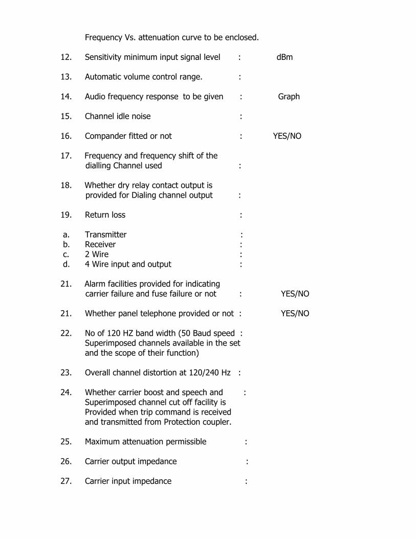
Frequency Vs. attenuation curve to be enclosed. 12. Sensitivity minimum input signal level : dBm 13. Automatic volume control range. : 14. Audio frequency response to be given : Graph 15. Channel idle noise : 16. Compander fitted or not : YES/NO 17. Frequency and frequency shift of the
dialling Channel used : 18. Whether dry relay contact output is
provided for Dialing channel output : 19. Return loss : a. Transmitter : b. Receiver : c. 2 Wire : d. 4 Wire input and output : 21. Alarm facilities provided for indicating
carrier failure and fuse failure or not : YES/NO
21. Whether panel telephone provided or not : YES/NO 22. No of 120 HZ band width (50 Baud speed :
Superimposed channels available in the set and the scope of their function) 23. Overall channel distortion at 120/240 Hz : 24. Whether carrier boost and speech and :
Superimposed channel cut off facility is Provided when trip command is received
and transmitted from Protection coupler. 25. Maximum attenuation permissible : 26. Carrier output impedance : 27. Carrier input impedance :

28. Speech channel (four wire) a. Modulator input impedance : b. Receiver output impedance : 29. a. AF distortion with max. power and 100% : Modulation. b. AF input (I) voice - 4wire (II) Ringing
(III) Superimposed channel (IV) voice – 2W c. AF output (I) voice - 4wire (II) Ringing (III) Superimposed channel (IV) voice -2W
30. Whether technical pamphlets and drawings : YES/NO
enclosed or not 31. Net weight of the equipment : Kgs. 32. Power consumption of the set and the : operating Voltage range. 33. Cubicle dimensions : 34. Whether vermin proof wire mesh provided : YES/NO 35. No. of co-axial cable connectors provided : 36. Type of output amplifier used (class A or :
Class AB) 37. D.C. standby power required with 100% : Modulation, speech and superimposed channels fully loaded. 38. Insulation level for Power supply and :
Carrier set. 39. Whether the carrier set offered confirm to :
IEC 495 and/or IS.9482-1980. If there is any deviation, it should be clearly indicated. 40. For programmable sets the additional information:
shall be furnished. Whether the AF&RF frequency is programmable at Site: Speech 300-3800 (for speech & pilot) RF (40-500KHz). If so the method may be detailed. i. No. of stages of modulation.
a. Transmitter : b. Receiver :

ii. Bandwidth of RF filter IF Filter : LP Filter : Tuning Range : iii. Pass band attenuation of filters. : iv. Whether all the filters provided in } :
Carrier sets are capable of site } tuning for Tx/Rx frequency range } of 40 to 500 KHz. } v. Indication for monitoring of the following
are available or not. a. Power Supply Voltage (DC) : b. Tx Pilot ON/Failure : c. Rx Pilot ON/Failure : d. Tx guard On/Failure. : e. Transmit level indicator. :
vi Provision of Loop test of Tx/Rx (local) : vii. Provision of loop testing of far end
Receiver. : 41. Any further details the tenderer may
wish to furnish. : -----------------------------------------------------------------------------------------------
Name of the firm : Signature of Bidder : Designation &Seal : Date :
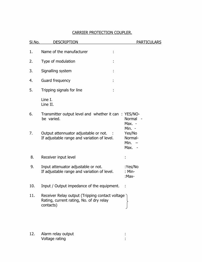
CARRIER PROTECTION COUPLER.
Sl.No. DESCRIPTION PARTICULARS 1. Name of the manufacturer : 2. Type of modulation : 3. Signalling system : 4. Guard frequency : 5. Tripping signals for line :
Line I. Line II.
6. Transmitter output level and whether it can : YES/NO- be varied. Normal - Max. - Min. - 7. Output attennuator adjustable or not. : Yes/No
If adjustable range and variation of level. Normal- Min. – Max. - 8. Receiver input level : 9. Input attenuator adjustable or not. :Yes/No
If adjustable range and variation of level. : Min- :Max-
10. Input / Output impedance of the equipment. : 11. Receiver Relay output (Tripping contact voltage
Rating, current rating, No. of dry relay contacts)
12. Alarm relay output :
Voltage rating :

Current rating : No. of dry contacts. 13. Command relay input : Voltage rating :
Current rating. : No. of contacts : 14. Power supply operation range : a) Operating Voltage Range : b) Operating Temperature Range : 15. Test facilities for local loop test : and End to End test are provided or not. 16. Visual and audible alarm provided or not : 17. Whether technical pamphlets : and drawing enclosed Or not 18. Transmission time (maximum) : 19. Performance under noise conditions.
a. Fail to trip PMC (max. actual transmission Time less than 20 ms) probability of Missing command (Dependability).
b. False trip PUC (probability of unwanted command) (Security) 20. Power consumption. : 21. Any other particulars the tenderer may wish:
to furnish. ----------------------------------------------------------------------------------------------- Name of the firm : Signature of Bidder : Designation &Seal : Date :
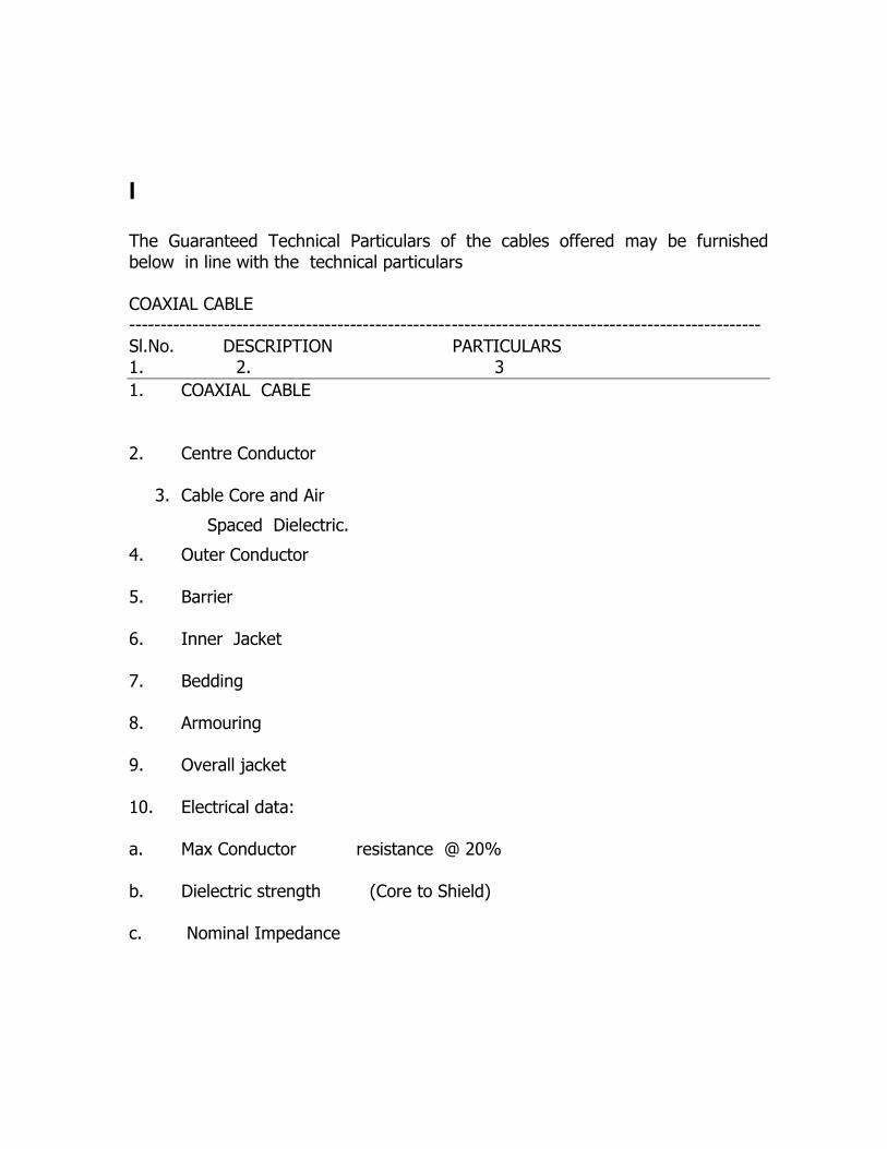
I The Guaranteed Technical Particulars of the cables offered may be furnished below in line with the technical particulars COAXIAL CABLE ----------------------------------------------------------------------------------------------------Sl.No. DESCRIPTION PARTICULARS 1. 2. 3 1. COAXIAL CABLE
2. Centre Conductor
3. Cable Core and Air
Spaced Dielectric.
4. Outer Conductor
5. Barrier
6. Inner Jacket
7. Bedding
8. Armouring
9. Overall jacket
10. Electrical data:
a. Max Conductor resistance @ 20%
b. Dielectric strength (Core to Shield)
c. Nominal Impedance

1. 2. 3 .----------------------------------------------------------------------------------------------------d. Nominal capacitance 1 KHZ. e. Mx. Attenuator
frequency (KHZ) (KHZ) db/km 10
60 300 500
11. Min.Bending radius for installation 12. Packing Min.Continuous length. 13. Manufactuerer's identification.
----------------------------------------------------------------------------------------------------

MULTICORE CABLE 0.6 MM/4 PAIR/TELEPHONE CABLE 0.6 MM/1 PAIR 0.6mm dia. Annealed Tinned copper conductor, PVC insulated, colour coded, 2 cores twisted to form a pair, pairs laid up, Aluminium Mylar shielded with drain wire, melinex taped, over-all PVC sheathed, screened Telephone Cables conforming to I.T.D. Specification No.S/WS-113C. Four pair Single pair 1. Wire diameter :
2. Dia. Over Insulation :
3. Thickness of Insulation :
4. Elongation. a) Conductor :
b) Insulation :
c) Sheath :
5. Tensile Strength.
a)Insulation :
b) Sheath :
6. Colour of pairs :
7. Laid up dia of pairs :
8. Mylar Tape :
9. Polythene Aluminium tape :
10. Drain wire :
11. Dia.Over shielded cable :
12. Overall diameter (Max.) :
13. Thickness of sheath (Min.) :
14. Colour of sheath :
15. Max. conductor resistance :
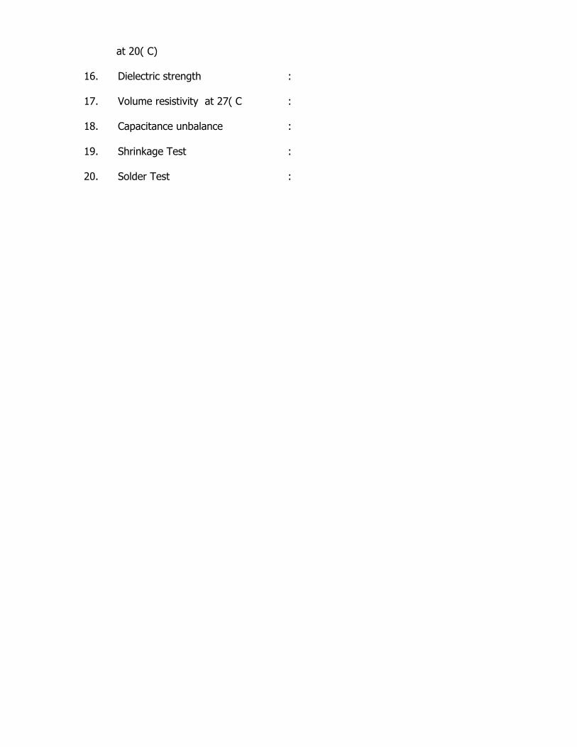
at 20( C)
16. Dielectric strength :
17. Volume resistivity at 27( C :
18. Capacitance unbalance :
19. Shrinkage Test :
20. Solder Test :

ANNEXURE-III
GUARANTEED TECHNICAL PARTICULARS.(EPAX)
1. Name & Address of the Manufacturer :
2. Type/Model :
3. Type of technology :
4. Architecture used
(32/64 bit Microprocessor) :
5. Method of mounting cubicle :
6. Method of connection to external circuits :
7. Cable Entry :
8. Literature :
9. Operating temperature range :
10. Operating relative humidity :
11. Operating voltage with range :
12. Power requirement :
13. Numbering scheme :
14. Maximum number of trunk lines :
15. Maximum number of subscriber lines :
16. No. of trunk lines per card :
17. No. of subscriber lines per card :
18. Method of extending capacity :
19. Method of implementing and modifying :
scheme
20. Speech signal levels : 4 wire transmit level=
4 wire receive level =
21. Facility for expansion :
22. PSTN/VSAT/VHF compatibility for future :
applications.
Signature of the tenderer.