bi series electronic control pocketbook pocket manual
TRANSCRIPT

subzero.com 800.222.7820
BI Series Electronic Control PocketbookPocket Manual

Page 2
PAGE 3
BUILT-IN SERIES
Basic Input Operations
• Unit ON/OFF
- Press POWER key.
• Adjusting Set-Point (Temperature Adjust)- Press COLDER or WARMER key of desired compartment
NOTE: Actual temperature is displayed 10 seconds afterlast keystroke.
• Icemaker System ON/OFF
- Press ICE key.
• Maximum Ice Production Feature ON/OFF
- Press MAX ICE key.
NOTE: Automatically converts to normal operation after24 hours.
• Door Ajar Alarm ON/OFF
- Press ALARM key.
• Air Purification Feature ON/OFF
- Press PURE AIR key.
• Accent Lighting System ON/OFF
- Press LIGHTS key.

Page 3
PAGE 4
BUILT-IN SERIES
Unique Input Operations
• Temperature Units Selection Mode (°F or °C Display)- Within first minute of switching unit on, press ALARM key
and POWER key simultaneously for 5 seconds.
NOTE: Mode will end 10 seconds after last keystroke.• Contrast Adjust Mode (LCD Contrast Level)
1. Within first minute of switching unit on, press COLDER,
WARMER and POWER keys simultaneously for 5 seconds.
(“c” appears at small digit, with “1”, “2”, “3”, “4” or “5” at right)
2. Press Colder or WARMER key to toggle
NOTE: Mode will end 10 seconds after last keystroke.• Tone Adjust Mode (Audible Chime Tone)
1. Within first minute of switching unit on, press COLDER,
WARMER and POWER keys simultaneously for 5 seconds
2. Press POWER key.
(“s” appears at small digit, with “HI” or “nO” or “Lo” at right)
3. Press Colder or WARMER key to toggle.
NOTE: Mode will end 10 seconds after last keystroke.
Page 4
PAGE 5
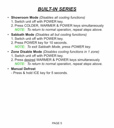
BUILT-IN SERIES• Showroom Mode (Disables all cooling functions)
1. Switch unit off with POWER key.
2. Press COLDER, WARMER & POWER keys simultaneously
NOTE: To return to normal operation, repeat steps above.• Sabbath Mode (Disables all but cooling functions)
1. Switch unit off with POWER key.
2. Press POWER key for 10 seconds.
NOTE: To exit Sabbath Mode, press POWER key.• Zone Disable Mode (Disables cooling functions in 1 zone)
1. Switch unit off with POWER key.
2. Press desired WARMER & POWER keys simultaneously
NOTE: To return to normal operation, repeat steps above.• Manual Defrost
- Press & hold ICE key for 5 seconds.
Page 5
PAGE 6
BUILT-IN SERIES
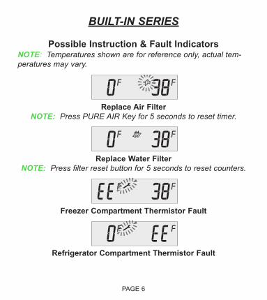
Possible Instruction & Fault IndicatorsNOTE: Temperatures shown are for reference only, actual tem-peratures may vary.
Replace Air Filter
NOTE: Press PURE AIR Key for 5 seconds to reset timer.
Replace Water Filter
NOTE: Press filter reset button for 5 seconds to reset counters.
Freezer Compartment Thermistor Fault
Refrigerator Compartment Thermistor Fault
Page 6
PAGE 7
BUILT-IN SERIES
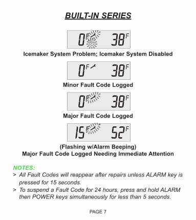
Icemaker System Problem; Icemaker System Disabled
Minor Fault Code Logged
Major Fault Code Logged
(Flashing w/Alarm Beeping)
Major Fault Code Logged Needing Immediate Attention
NOTES:> All Fault Codes will reappear after repairs unless ALARM key is
pressed for 15 seconds.> To suspend a Fault Code for 24 hours, press and hold ALARM
then POWER keys simultaneously for less than 5 seconds.

Page 7
PAGE 8
BUILT-IN SERIES
Service Input Operations
• Diagnostic Mode (Observe Current Thermistor Temperatures)NOTE: Keystrokes for Diagnostic Mode and Fault Code RecallMode are the same.1. Press COLDER and POWER simultaneously, then release.
If no Fault codes observed, temperature appears at left with
location code at right.
2. Press Colder or WARMER key to toggle.
Refrigerator Compartment
Refrigerator Evaporator
Freezer Compartment
Freezer Evaporator
Refrigerator Drawers (Not Active)
Condenser (Not Active)
CODE LOCATION
THERMISTOR LOCATION CODE TABLE
Ambient

Page 8
PAGE 9
BUILT-IN SERIES
DIAGNOSTIC MODE NOTES:> Mode will end 20 seconds after last keystroke.> Pressing and holding COLDER and POWER keys for 10
seconds will initiate Manual Zone Disable Mode.> If “Sh” and “r” appear when initiating Diagnostic Mode, unit is
in Showroom Mode.> If “EE” appears when in Diagnostic Mode, thermistor in that
location is defective.> There is no thermistor in the drawers, so “EE” will appear at
left of the “dr”.> There is no thermistors on the condenser, so “EE” will
appear at left of the “Cn”.> The ambient thermistor is part of the control board. It is not
a separate component.

Page 9
PAGE 10
BUILT-IN SERIES
Service Input Operations
• Fault Code Recall Mode (Observe Stored Fault Codes)NOTE: Keystrokes for Fault Code Recall Mode and DiagnosticMode are the same.1. Press COLDER and POWER simultaneously, then release.
2. Press Colder or WARMER key to toggle.
NOTES:> Mode will end 10 seconds after last keystroke.> Pressing and holding COLDER and POWER keys for 10
seconds will initiate Manual Zone Disable Mode.> If “Sh” and “r” appear when initiating Fault Code Recall
Mode, unit is in Showroom Mode.> To clear fault codes, press ALARM key for 15 seconds.> If Fault Codes are present but the desire is to view current
temperature readings from thermistors (Diagnostic Mode),then press ALARM key; this will shift electronic controlsystem into Diagnostic Mode.
Page 10
PAGE 11
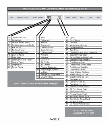
PURE AIR WARMER COLDER WARMER REWOP MRALA REDLOCMAX ICE ICE MAKER LIGHTS
FAULT CODE TABLE WITH LCD CORRELATION DIAGRAM ( PAGE 1 of 2 )
10152030354044455060909598
Thermistor FaultsRelay FaultsDefrost Heater FaultsIce/Water/Accessory FaultsFan FaultsRuntime FaultsGlass Heater FaultsLighting FaultsFlow MeterLoad/Component FaultsControl FaultsDiagnosticsPower Faults
0123456789AdFHLrU
MiscRefrigeratorFreezerCondenserDefrost SystemControl SystemCompressorsAmbientIcemakerDispenserAir PurifierTC DrawerFreezer EvaporatorHigh Voltage SystemLightingRefrigerator EvaporatorWater Systems
00010205060709101112202122253033343536 373839404243444546
OpenShort/ClosedUnstableMiswire normal tempsMiswire overheatBad OhmsToo Warm/Large Temp DifferentialSecond Device OpenSecond Device Short/ClosedSecond Device UnstableThird Device OpenThird Device Short/ClosedThird Device UnstableDiagnostics FailureValve Enabled Too LongSpeed Setting too LowSpeed Setting too HighFan speed errorFan current too lowFan current too highFan Power Output FaultDC Fan Output FaultExcessive runtimePrimary Heater FaultSecondary Heater FaultDoor Heater Output FaultBurned out LightNo Position/State Detect
NOTE: These Columns are repeated on next page
NOTE: This Column iscontinued on next page

Page 11
PAGE 12
PURE AIR WARMER COLDER WARMER REWOP MRALA REDLOCMAX ICE ICE MAKER LIGHTS
FAULT CODE TABLE WITH LCD CORRELATION DIAGRAM ( PAGE 2 of 2 )
10152030354044455060909598
Thermistor FaultsRelay FaultsDefrost Heater FaultsIce/Water/Accessory FaultsFan FaultsRuntime FaultsGlass Heater FaultsLighting FaultsFlow MeterLoad/Component FaultsControl FaultsDiagnosticsPower Faults
0123456789AdFHLrU
MiscRefrigeratorFreezerCondenserDefrost SystemControl SystemCompressorsAmbientIcemakerDispenserAir PurifierTC DrawerFreezer EvaporatorHigh Voltage SystemLightingRefrigerator EvaporatorWater Systems
50555660656670717273747580818283848586879092939596979899
Open HeaterTriac OpenTriac ShortNo Load/Load OpenStuck at Dispenser Water Valve OutStuck at Ice Water Valve OutBad Flash WriteFlash InitializedFlash Memory BadInvalid Log Fault ChecksumInvalid E2 ChecksumInvalid Model E2 ChecksumNo CommunicationCommunications Time-outPartial CommunicationsBad Micro CommunicationMicro InitializationDisplay FailureToo SlowNo FlowFraming ErrorsExcessive CollisionsData OverrunFMEA ErrorCalibration or Low Signal ErrorQuantum SPIBrownoutOther
NOTE: These Columns are repeated from last page
NOTE: This Column iscontinued from last page
Page 12
PAGE 13
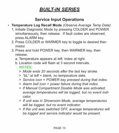
BUILT-IN SERIES
Service Input Operations
• Temperature Log Recall Mode (Observe Average Temp Data)1. Initiate Diagnostic Mode by pressing COLDER and POWER
simultaneously, then release. If fault codes are observed,
press ALARM key.
2. Press COLDER or WARMER key to toggle to desired ther-
mistor.
3. Press and hold POWER key, then WARMER key, then
release.
a. Temperature appears at left; index at right.
b. Location code will flash at 3 second intervals.
NOTES:> Mode ends 20 seconds after the last key stroke.> “bL” at left = blank, no temperature data.> Service icon = POWER key pressed during that index.> Alarm bell icon = power failure during that index.> If Manual Compartment Disable Mode was activated,
average temperatures will be logged, but no event indi-cator.
> If unit was in Showroom Mode, average temperatureswill be logged, but no event indicator.
> If the unit was switched OFF, average temperatures willbe logged and service indicator would be present.

Page 13
PAGE 14
BUILT-IN SERIES
Service Input Operations
• Model Configuration Mode (Apply Appropriate Model BatchFiles to E-Control)1. Initiate Diagnostic Mode by pressing COLDER and POWER
simultaneously, then release. If fault codes are observed,
press ALARM key.
2. Press and hold POWER key for 10 seconds.
3. Press COLDER or WARMER key to toggle through model
codes; stop when appropriate code is displayed.
4. Press POWER key, “Pr g” appears.
5. Press POWER key again within 5 seconds.
NOTES:> Second press of POWER key must occur w/in 5 seconds.> With no keys pressed, mode automatically ends 30 seconds
after last key stroke.> If the ALARM key is pressed, or if WARMER and COLD-
ER keys are pressed during Model Configuration Mode,mode is exited.
> Model code sequence is as shown in tables on next page.
Page 14
PAGE 15
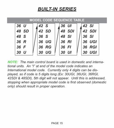
36 U 48 SD 48 S 36 R 36 F 30 U
42 S 42 SD 36 S 36 UG 36 RG 30 UG
36 UI 48 SDI 48 SI 36 RI 36 FI 30 UI
42 SI 42 SDI 36 SI 36 UGI 36 RGI 30 UGI
MODEL CODE SEQUENCE TABLE
BUILT-IN SERIES
NOTE: The main control board is used in domestic and interna-tional units. An “I” at end of the model code indicates anInternational model code. Currently only 4 digits can be dis-played, so if code is 5 digits long (Ex: 30UGI, 36UGI, 36RGI,42SDI & 48SDI), 5th digit will not appear. Until this is addressed,stopping when appropriate model code is first observed (domesticonly) should result in proper operation.

Page 15
PAGE 16
BUILT-IN SERIES
Service Input Operations
• Manual Component Activation Mode (Individual ComponentActivation)1. Initiate Diagnostic Mode by pressing COLDER and POWER
simultaneously, then release. If fault codes are observed,
press ALARM key.
2. Press and hold desired zone’s COLDER key for 10 seconds.
(Chosen zone’s components can forced to ON for five (5)
minutes, or OFF using WARMER or COLDER keys)
3. Press WARMER key to activate next component; press
COLDER key to activate previous component.
NOTES:> All temperatures displayed are current, without weighted
averaging or offsets.> With no keys pressed, mode automatically ends 5 minutes
after last key stroke.> Pressing any key (other than POWER or ALARM) during
this mode restarts the 5 minute timer.> Pressing ALARM key during this mode will end the mode.> Pressing POWER key during this mode will force control
into Diagnostic Mode.>“-84F” or “-64c” will appear in place of temperature if ther-
mistor is open or missing.
Page 16
PAGE 17
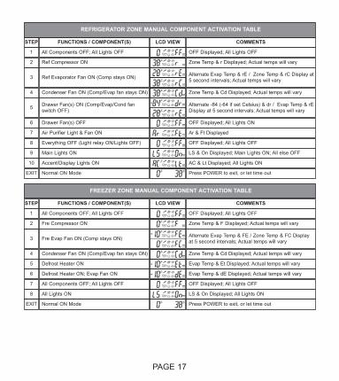
STEP FUNCTIONS / COMPONENT(S)
1
3
2
4
5
6
7
8
9
10
LCD VIEW COMMENTS
All Components OFF; All Lights OFF OFF Displayed; All Lights OFF
Ref Compressor ON Zone Temp & r Displayed; Actual temps will vary
Ref Evaporator Fan ON (Comp stays ON) Alternate Evap Temp & rE / Zone Temp & rC Display at5 second intervals; Actual temps will vary
Condenser Fan ON (Comp/Evap fan stays ON) Zone Temp & Cd Displayed; Actual temps will vary
Drawer Fan(s) ON (Comp/Evap/Cond fanswitch OFF)
Alternate -84 (-64 if set Celsius) & dr / Evap Temp & rEDisplay at 5 second intervals; Actual temps will vary
Drawer Fan(s) OFF OFF Displayed; All Lights ON
Air Purifier Light & Fan ON Ar & Ft Displayed
Everything OFF (Light relay ON/Lights OFF) OFF Displayed; All Lights OFF
Main Lights ON LS & On Displayed; Main Lights ON; All else OFF
Accent/Display Lights ON AC & Lt Displayed; All Lights ON
Normal ON Mode Press POWER to exit, or let time outEXIT
STEP FUNCTIONS / COMPONENT(S)
1
3
2
4
5
6
7
8
LCD VIEW COMMENTS
All Components OFF; All Lights OFF OFF Displayed; All Lights OFF
Fre Compressor ON Zone Temp & F Displayed; Actual temps will vary
Fre Evap Fan ON (Comp stays ON) Alternate Evap Temp & FE / Zone Temp & FC Displayat 5 second intervals; Actual temps will vary
Condenser Fan ON (Comp/Evap fan stays ON) Zone Temp & Cd Displayed; Actual temps will vary
Defrost Heater ON Evap Temp & Et Displayed; Actual temps will vary
Defrost Heater ON; Evap Fan ON Evap Temp & dE Displayed; Actual temps will vary
All Components OFF; All Lights OFF OFF Displayed; All Lights OFF
All Lights ON LS & On Displayed; All Lights ON
Normal ON Mode Press POWER to exit, or let time outEXIT
REFRIGERATOR ZONE MANUAL COMPONENT ACTIVATION TABLE
FREEZER ZONE MANUAL COMPONENT ACTIVATION TABLE

Page 17
PAGE 18
BUILT-IN SERIES
Service Input Operations
• Self-Test Mode (Forced E-Control Cycling)1. Initiate Diagnostic Mode by pressing COLDER and POWER
simultaneously, then release. If fault codes are observed,
press ALARM key.
2. Press and hold COLDER, WARMER and POWER key, then
release.
NOTES:> Self-test lasts approximately 5 seconds.> After running Self Test Mode, Fault Code Recall Mode
must be initiated to view any fault codes that may have
been logged during the self test.