bidirectional wafer knife gate valve - …€¦ · · 2016-08-29this knife‐gate valve’s main...
TRANSCRIPT

K N I F E - G A T E V A L V E S G L S E R I E S
C.M.O.
Amategui Aldea 142, 20400 Txarama‐Tolosa (SPAIN) TEC‐GL.EN12
Tel. National: 902.40.80.50 Fax: 902.40.80.51 / Tel. International: 34.943.67.33.99 Fax: 34.943.67.24.40
[email protected] http://www.cmo.es Page1
09/03/2016
‐Bidirectional wafer‐design knife gate valve.
‐“Monoblock” one‐piece cast iron body.
‐Stainless steel gate. Two rubber sleeves. ‐Provides high flow rates with low pressure drop.
‐Various seat materials available.
‐Face‐to‐face dimension in accordance with C.M.O. standard.
General Applications: ‐This knife gate valve is suitable for working in the mining industry,
in loaded fluid transport lines, such as: water with stones, sludge,
etc. and in general it is used for abrasive fluids in the chemical
industry and waste water. Designed for the following applications: ‐Mining ‐ Sewage treatment ‐ Electrical power stations ‐ Chemical plants ‐ Energy Sector ‐ Thermal power stations
Sizes: DN50 to DN1400 (larger sizes on request).
‐ The pressures indicated in the table, can be used in either of the
valve’s two directions.
‐ Other pressures on request.
Flange drill hole: DIN PN10 & ANSI B16.5 (150 LB)
Other Common Flanges: DIN PN 16 JIS standard
DIN PN 6 Australian standard
DIN PN 25 British standard
Directives: Machinery Directive: DIR 2006/42/EC (MACHINERY) Pressure Equipment Directive: DIR 97/23/EC (PED) ART.3, P.3
Potential Explosive Atmospheres Directive: DIR 94/9/EC (ATEX) CAT.3 ZONE 2 and 22
GD for further information on categories and zones please contact the C.M.O.
Technical‐Commercial Dept.
Quality Dossier: ‐All valves are tested hydrostatically at C.M.O. and material and test certificates can
be provided. ‐Body test = working pressure x 1.5.
‐Seat test = working pressure x 1.1.
Working (ΔP): Maximum ΔP
DN50 to DN600 10 kg/cm2
DN700 to DN900 6 kg/cm2
DN1000 to DN1400 4 kg/cm2
BIDIRECTIONAL WAFER Knife Gate Valve
Fig. 1
K N I F E - G A T E V A L V E S G L S E R I E S
C.M.O.
Amategui Aldea 142, 20400 Txarama‐Tolosa (SPAIN) TEC‐GL.EN12
Tel. National: 902.40.80.50 Fax: 902.40.80.51 / Tel. International: 34.943.67.33.99 Fax: 34.943.67.24.40
[email protected] http://www.cmo.es Page2
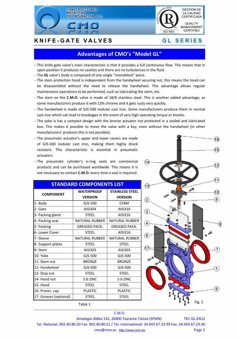
This knife‐gate valve’s main characteristic is that it provides a full continuous flow. This means that in open position it produces no cavities and there are no turbulences in the fluid.
The GL valve’s body is composed of one single “monoblock” piece.
The stem protection hood is independent from the handwheel securing nut, this means the hood can
be disassembled without the need to release the handwheel. This advantage allows regular
maintenance operations to be performed, such as lubricating the stem, etc. The stem on the C.M.O. valve is made of 18/8 stainless steel. This is another added advantage, as
some manufacturers produce it with 13% chrome and it gets rusty very quickly.
The handwheel is made of GJS‐500 nodular cast iron. Some manufacturers produce them in normal
cast iron which can lead to breakages in the event of very high operating torque or knocks.
The yoke is has a compact design with the bronze actuator nut protected in a sealed and lubricated
box. This makes it possible to move the valve with a key, even without the handwheel (in other
manufacturers’ products this is not possible). The pneumatic actuator’s upper and lower covers are made
of GJS‐500 nodular cast iron, making them highly shock
resistant. This characteristic is essential in pneumatic
actuators. The pneumatic cylinder’s o‐ring seals are commercial
products and can be purchased worldwide. This means it is
not necessary to contact C.M.O. every time a seal is required.
STANDARD COMPONENTS LIST
COMPONENT WATERPROOF
VERSION
STAINLESS STEEL
VERSION
1‐ Body GJS‐500 CF8M
2‐ Gate AISI304 AISI316
3‐ Packing gland STEEL AISI316
4‐ Packing seal. NATURAL RUBBER NATURAL RUBBER
5‐ Packing GREASED PACK. GREASED PACK.
6‐ Lower Cover STEEL AISI316
7‐ Sleeve NATURAL RUBBER NATURAL RUBBER
8‐ Support plates STEEL STEEL
9‐ Stem AISI303 AISI303
10‐ Yoke GJS‐500 GJS‐500
11‐ Stem nut BRONZE BRONZE
12‐ Handwheel GJS‐500 GJS‐500
13‐ Stop nut STEEL STEEL
14‐ Hood nut 5.6 ZINC 5.6 ZINC
15‐ Hood STEEL STEEL
16‐ Protec. cap PLASTIC PLASTIC
17‐ Greaser (optional) STEEL STEEL
Advantages of CMO’s "Model GL"
Fig. 2Table 1

K N I F E - G A T E V A L V E S G L S E R I E S
C.M.O.
Amategui Aldea 142, 20400 Txarama‐Tolosa (SPAIN) TEC‐GL.EN12
Tel. National: 902.40.80.50 Fax: 902.40.80.51 / Tel. International: 34.943.67.33.99 Fax: 34.943.67.24.40
[email protected] http://www.cmo.es Page3
1‐ BODY One‐piece reinforced cast iron body.
The body provides a full continuous flow. This means that in open position it produces no cavities and,
therefore, there are no turbulences in the fluid and the load loss is minimal. For diameters greater than DN600 the body is machine‐welded with the necessary reinforcements to
resist the maximum working pressure. Full port designed to provide high flow rates with low pressure drop.
The body’s internal design prevents any build up of solids in the seat area. The standard manufacturing materials are GJS‐500 and CF8M stainless steel. Other materials such as:
A216WCB carbon steel and stainless steel alloys (AISI316Ti, Duplex, 254SMO, Uranus B6, Ni‐Resist,
Ductile Ni‐Resist, ...) are available on request. As standard, iron or carbon steel valves are painted with
an anti‐corrosive protection of 80 microns of EPOXY (colour RAL 5015). Other types of anti‐corrosive
protections are available on request.
2‐ GATE The standard manufacturing materials are AISI304 stainless steel in valves with GJS‐500 body and
AISI316 stainless steel in valves with CF8M body. Other materials or combinations can be supplied on
request. The gate is polished on both sides to provide a smooth contact surface with the resilient seat. At the
same time, the sharp edges on the gate are rounded to prevent the seal from being cut. There are
different degrees of polishing, anti‐abrasion treatments and various options to adapt the valves to the
customer’s requirements.
3‐ SEAT: (watertight) The seat on the GL valve is composed of two rubber
sleeves, located on either side of the body symmetrically.
The sleeves are made of natural rubber with a metal core
which helps to keep their shape and at the same time
prevents deformations. Whilst the valve is in open
position, the sleeves' elasticity ensures they are joined
together permanently, preventing the accumulation of
solids between the two parts of the body. The GL valve is designed for abrasive fluids, and therefore,
the sleeves protect the entire surface of the body which
would be exposed to the abrasive flow. Regarding the
sleeves’ maintenance, these can be replaced from outside
of the valve, making operation easier. It is a seat with two
symmetrical parts, below we show a diagram of the seat
(fig.3).
Resilient seat materials
NATURAL RUBBER
This is the standard resilient seat fitted on C.M.O. GL model valves. It can be used in multiple
applications at temperatures no higher than 90°C with abrasive products and it provides the valve with
100% watertight integrity. Application: fluids in general.
DESIGN CHARACTERISTICS
Fig. 3

K N I F E - G A T E V A L V E S G L S E R I E S
C.M.O.
Amategui Aldea 142, 20400 Txarama‐Tolosa (SPAIN) TEC‐GL.EN12
Tel. National: 902.40.80.50 Fax: 902.40.80.51 / Tel. International: 34.943.67.33.99 Fax: 34.943.67.24.40
[email protected] http://www.cmo.es Page4
EPDM
Recommended for temperatures no higher than 90°C*, it provides the valve with 100% watertight
integrity. Application: water and acids.
NITRILE
It is used in fluids containing fats or oils at temperatures no higher than 90°C*. It provides the valve with
100% watertight integrity.
VITON
Suitable for corrosive applications and continuous high temperatures of up to 190°C and peaks of
210°C. It provides the valve with 100% watertight integrity.
NOTE: More details and other materials available on request.
* EPDM and nitrile: is possible until serving temperature Max.: 120°C under request.
4‐ PACKING
C.M.O.’s standard packing is composed of a specially designed EPDM O‐ring which provides watertight
integrity between the body and the gate, preventing any type of leakage to the atmosphere. It also has a
greased packing strip to help the valve’s operation during the opening and closing functions. They are
located in an easily accessible place and can be replaced without dismantling the valve from the
pipeline. 5‐ STEM The stem on the C.M.O. valve is made of 18/8 stainless steel. This characteristic provides high resistance
and excellent corrosion‐resistant properties.
The valve design can be rising stem or non‐rising stem. When a rising stem is required for the valve a
stem hood is supplied to protect the stem from contact with dust and dirt, besides keeping it lubricated.
6‐ PACKING GLAND
The packing gland allows uniform force and pressure to be applied to the packing to ensure watertight
integrity.
As standard, valves with steel body include steel packing glands, whilst valves with stainless steel body
have stainless steel packing glands.
7‐ ACTUATORS
All types of actuators can be supplied, with the advantage that the C.M.O. design is fully
interchangeable.
This design allows the customer to change the actuators themselves and no extra assembly accessories
are required. A design characteristic of C.M.O. valves is that all actuators are interchangeable.
SEAT/SEALS Material Max. T. (°C) Applications
Natural rubber 90 General
EPDM (E) 90 * Water, non‐mineral acids and oils
Nitrile (N) 90 * Hydrocarbons, oils and greases
Viton (V) 200 Hydrocarbons and solvents
Table 2

K N I F E - G A T E V A L V E S G L S E R I E S
C.M.O.
Amategui Aldea 142, 20400 Txarama‐Tolosa (SPAIN) TEC‐GL.EN12
Tel. National: 902.40.80.50 Fax: 902.40.80.51 / Tel. International: 34.943.67.33.99 Fax: 34.943.67.24.40
[email protected] http://www.cmo.es Page5
Manual: Automatic: Handwheel with rising stem Electric actuator Handwheel with non‐rising stem Pneumatic cylinder Chainwheel Hydraulic cylinder Lever Gear Box Others (square nut,...)
Wide Range of Accessories Available: Mechanical stops Locking devices Emergency manual actuators Solenoid valves Positioners Limit switches Proximity switches Straight floor stand (Fig. 6) Leaning floor stand (Fig. 5)
Stem extensions have also been developed, allowing the actuator to be located far away from the valve, to suit all needs. Please consult our technicians beforehand.
Hydraulic actuator
Pneumatic actuator
Electric‐motor actuator
HandwheelGear box
Handwheel with rising stem
Fig. 5 Fig. 6
Fig. 4

K N I F E - G A T E V A L V E S G L S E R I E S
C.M.O.
Amategui Aldea 142, 20400 Txarama‐Tolosa (SPAIN) TEC‐GL.EN12
Tel. National: 902.40.80.50 Fax: 902.40.80.51 / Tel. International: 34.943.67.33.99 Fax: 34.943.67.24.40
[email protected] http://www.cmo.es Page6
Different accessories are available to adapt the valve to specific working conditions such as:
Mirror Polished Gate: The mirror polished gate is especially recommended in the food industry and, as
standard, in applications in which solids can stick to the gate. It is an alternative to ensure the solids
slide off and do not stick to the gate. PTFE Lined Gate: As with the mirror polished gate, it improves the valve’s resistance to products that
can stick to the gate. Stellited Gate: Stellite is added to the gate’s internal circle to
protect it from abrasion.
Scraper in the Packing: Its function is to clean the gate during
the opening movement and prevent possible damage to the
packing. Heating Jacket: Recommended in applications in which the
fluid can harden and solidify inside the valve’s body. An
external jacket keeps the body temperature constant,
preventing the fluid from solidifying. Flushing Holes in Body: Several holes are drilled in the body to
flush air, steam or other fluids out with the aim of cleaning the
valve seat before sealing. Solenoid valves (Fig. 7): For air distribution to pneumatic
actuators. Connection boxes, wiring and pneumatic piping: Units
supplied fully assembled with all the necessary accessories. Mechanical Limit Switches, Inductive Switches and
Positioners: Limit switches or inductive switches are installed
to indicate precise valve position, as well as positioners to
indicate continuous position (Fig. 7). Connection boxes, wiring and pneumatic piping: Units supplied fully assembled with all the necessary
accessories. Mechanical Locking Device: Allows the valve to be mechanically locked in a set position for long
periods. Stroke Limiting Mechanical Stops: They allow the stroke to be mechanically adjusted, limiting the
valve’s desired run. Emergency manual actuator (hand wheel /gear box) (Fig. 7): Allows manual operation of the valve in
the event of power or air failure. Interchangeable actuators: All actuators are easily interchangeable. Actuator or Yoke Support: Made of EPOXY‐coated steel (or stainless steel on request), its robust design
gives it great rigidity in order to resist the most adverse operation conditions. Epoxy Coating: All cast iron and carbon steel bodies and components on C.M.O. valves are EPOXY
coated, giving the valves great resistance to corrosion and an excellent finish. C.M.O.’s standard colour
is blue, RAL‐5015. Gate Safety Protection: In accordance with European Safety Standards (“EC” marking), C.M.O.
automated valves are equipped with gate guards, to prevent any objects from being accidentally
caught in the gate.
ACCESSORIES AND OPTIONS
Fig. 7
Emergency manual actuator
Solenoid valve
Limit switches

K N I F E - G A T E V A L V E S G L S E R I E S
C.M.O.
Amategui Aldea 142, 20400 Txarama‐Tolosa (SPAIN) TEC‐GL.EN12
Tel. National: 902.40.80.50 Fax: 902.40.80.51 / Tel. International: 34.943.67.33.99 Fax: 34.943.67.24.40
[email protected] http://www.cmo.es Page7
When the valve needs to be operated from a distance, the following different types of actuators can be fitted:
1 ‐ Extension: Floor Stand. This extension is performed by coupling a rod to the stem. By defining
the length of the rod, the desired extension is achieved. A floor stand is
normally installed to support the actuator. The definition variables are as follows:
H1: Distance from the valve’s shaft to the base of the stand. d1: Separation from the wall to the end of the connecting flange.
Characteristics:
‐ It can be coupled to any type of actuator.
‐ A stem support‐guide (Fig. 8) is recommended every 1.5m.
‐ The standard floor stand is 800mm high (Fig. 9). Other floor stand
measurements available on request. ‐ A position indicator can be fitted to determine the valve’s percentage
of opening.
‐ Possibility of leaning floor stand (Fig. 10).
COMPONENTSLLISTComponent Standard Version
Stem AISI 303
Rod AISI 304
Support‐guide EPOXI coated carbon steel
Guide Nylon
Stand EPOXI coated GJS‐500
TYPES OF EXTENSION
Table 3
Fig. 8
Fig. 10
Fig. 9
Fig. 8

K N I F E - G A T E V A L V E S G L S E R I E S
C.M.O.
Amategui Aldea 142, 20400 Txarama‐Tolosa (SPAIN) TEC‐GL.EN12
Tel. National: 902.40.80.50 Fax: 902.40.80.51 / Tel. International: 34.943.67.33.99 Fax: 34.943.67.24.40
[email protected] http://www.cmo.es Page8
2 ‐ Extension: Pipe (Fig. 11) Consists of raising the actuator. The pipe will rotate in the same direction as the handwheel when the valve is operated but it always remains at the same height. The definition variables are as follows: H1: Distance from the valve’s shaft to the desired height of the actuator. d1: Separation from the wall to the end of the connecting flange. Characteristics: ‐ Standard actuators: Handwheel and “Square Nut” ‐ A pipe support‐guide is recommended every 1.5m. ‐ The standard materials are: EPOXY coated carbon steel or stainless steel.
3 ‐ Extension: Extended Support Plates (Fig. 12) When a short extension is required, it can be achieved by extending the support plates. An intermediate yoke can be fitted to reinforce the support plates’ structure.
4 ‐ Extension: Universal Joint (Fig. 13) If the valve and the actuator are not in correct alignment, the problem can be resolved by fitting a universal joint.
Fig. 11
Fig. 12
Fig. 13

K N I F E - G A T E V A L V E S G L S E R I E S
C.M.O.
Amategui Aldea 142, 20400 Txarama‐Tolosa (SPAIN) TEC‐GL.EN12
Tel. National: 902.40.80.50 Fax: 902.40.80.51 / Tel. International: 34.943.67.33.99 Fax: 34.943.67.24.40
[email protected] http://www.cmo.es Page9
B = Max. width of the valve (without actuator).
P = Max. height of the valve (without actuator).
Options: ‐ Locking devices. ‐ Extensions: stand, pipe, plates...
‐ DN higher than those give in the table.
Actuator including: ‐ Handwheel. ‐ Stem. ‐ Nut. ‐ Stem protection hood.
Available: DN50 to DN1000, other DN on request.
From DN350 (included) the actuator is with
geared motor.
Other pressures on request.
DN ΔP
(Kg/cm2) DRAW (Nw)
TORQUE (Nm)
A B C P D Hv ØV WEIGHT
(Kg) r
(B.S.P.)50 10 920 2 54 109 106 280 319 451 225 12 1/4”
65 10 1553 4 54 109 113 306 345 502 225 14 1/4”
80 10 2352 5 57 109 122 332 372 553 225 18 1/4"
100 10 3674 8 57 109 136 368 407 589 225 21 1/4"
125 10 5739 16 64 126 153 421 474 675 325 26 1/4"
150 10 8267 24 64 126 168 466 519 759 325 33 1/4"
200 10 14709 42 76 126 199 565 618 958 325 52 3/8”
250 10 23001 89 76 197 234 626 750 1127 450 74 1/2"
300 10 33156 129 83 197 272 739 838 1230 450 98 1/2"
350 10 45198 175 83 350 297 842 ‐‐ ‐‐ ‐‐ ‐‐ 1/2"
400 10 59178 263 96 350 330 933 ‐‐ ‐‐ ‐‐ ‐‐ 3/4"
450 10 74891 333 96 350 355 1019 ‐‐ ‐‐ ‐‐ ‐‐ 3/4"
500 10 92469 506 121 380 391 1156 ‐‐ ‐‐ ‐‐ ‐‐ 3/4"
600 10 133494 730 121 400 461 1338 ‐‐ ‐‐ ‐‐ ‐‐ 1”
700 6 109909 601 182 400 534 1425 ‐‐ ‐‐ ‐‐ ‐‐ 1”
750 6 126159 690 188 400 559 1520 ‐‐ ‐‐ ‐‐ ‐‐ 1”
800 6 143530 931 206 400 584 1615 ‐‐ ‐‐ ‐‐ ‐‐ 1”
900 6 182412 1183 225 400 649 1823 ‐‐ ‐‐ ‐‐ ‐‐ 1”
1000 4 151073 980 240 440 699 1992 ‐‐ ‐‐ ‐‐ ‐‐ 1”
HANDWHEEL with rising stem
Table 4
Fig. 14

K N I F E - G A T E V A L V E S G L S E R I E S
C.M.O.
Amategui Aldea 142, 20400 Txarama‐Tolosa (SPAIN) TEC‐GL.EN12
Tel. National: 902.40.80.50 Fax: 902.40.80.51 / Tel. International: 34.943.67.33.99 Fax: 34.943.67.24.40
[email protected] http://www.cmo.es Page10
Suitable when no size limitations exist.
B = Max. width of the valve (without actuator).
P = Max. height of the valve (without actuator).
Options: ‐ Square nut.
‐ Locking devices. ‐ Extensions: stand, pipe, plates...
‐ DN higher than those give in the table.
Actuator including: ‐ Handwheel. ‐ Stem. ‐ Guide bearings on the yoke. ‐ Nut.
Available: DN50 to DN1000, other DN on request.
From DN350 (included) the actuator is with geared motor.
Other pressures on request.
DN ΔP
(Kg/cm2) DRAW (Nw)
TORQUE(Nm)
A B C P D ØV r
(B.S.P.)
50 10 920 2 54 109 106 280 319 225 1/4”
65 10 1553 4 54 109 113 306 345 225 1/4”
80 10 2352 5 57 109 122 332 372 225 1/4"
100 10 3674 8 57 109 136 368 407 225 1/4"
125 10 5739 16 64 126 153 421 474 325 1/4"
150 10 8267 24 64 126 168 466 519 325 1/4"
200 10 14709 42 76 126 199 565 618 325 3/8”
250 10 23001 89 76 197 234 626 750 450 1/2"
300 10 33156 129 83 197 272 739 838 450 1/2"
350 10 45198 175 83 350 297 842 ‐‐ ‐‐ 1/2"
400 10 59178 263 96 350 330 933 ‐‐ ‐‐ 3/4"
450 10 74891 333 96 350 355 1019 ‐‐ ‐‐ 3/4"
500 10 92469 506 121 380 391 1156 ‐‐ ‐‐ 3/4"
600 10 133494 730 121 400 461 1338 ‐‐ ‐‐ 1”
700 6 109909 601 182 400 534 1425 ‐‐ ‐‐ 1”
750 6 126159 690 188 400 559 1520 ‐‐ ‐‐ 1”
800 6 143530 931 206 400 584 1615 ‐‐ ‐‐ 1”
900 6 182412 1183 225 400 649 1823 ‐‐ ‐‐ 1”
1000 4 151073 980 240 440 699 1992 ‐‐ ‐‐ 1”
HANDWHEEL with Non‐Rising Stem
Table 5
Fig. 15
K N I F E - G A T E V A L V E S G L S E R I E S
C.M.O.
Amategui Aldea 142, 20400 Txarama‐Tolosa (SPAIN) TEC‐GL.EN12
Tel. National: 902.40.80.50 Fax: 902.40.80.51 / Tel. International: 34.943.67.33.99 Fax: 34.943.67.24.40
[email protected] http://www.cmo.es Page11
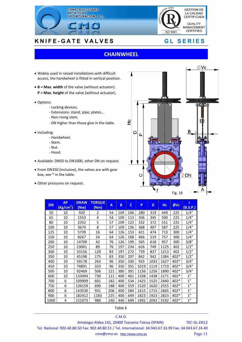
Widely used in raised installations with difficult access, the handwheel is fitted in vertical position.
B = Max. width of the valve (without actuator).
P = Max. height of the valve (without actuator).
Options: ‐ Locking devices. ‐ Extensions: stand, pipe, plates... ‐ Non‐rising stem.
‐ DN higher than those give in the table.
Including: ‐ Handwheel. ‐ Stem. ‐ Nut. ‐ Hood.
Available: DN50 to DN1000, other DN on request.
From DN350 (inclusive), the valves are with gear box, see * in the table.
Other pressures on request.
DN ΔP
(Kg/cm2)DRAW (Nw)
TORQUE(Nm)
A B C P D Hc ØVc r
(B.S.P.)
50 10 920 2 54 109 106 280 319 449 225 1/4” 65 10 1553 4 54 109 113 306 345 500 225 1/4” 80 10 2352 5 57 109 122 332 372 551 225 1/4" 100 10 3674 8 57 109 136 368 407 587 225 1/4" 125 10 5739 16 64 126 153 421 474 713 300 1/4" 150 10 8267 24 64 126 168 466 519 757 300 1/4" 200 10 14709 42 76 126 199 565 618 957 300 3/8” 250 10 23001 89 76 197 234 626 749 1125 402 1/2" 300 10 33156 129 83 197 272 739 837 1213 402 1/2" 350 10 45198 175 83 350 297 842 942 1384 402* 1/2" 400 10 59178 263 96 350 330 933 1033 1627 402* 3/4" 450 10 74891 333 96 350 355 1019 1119 1719 402* 3/4" 500 10 92469 506 121 380 391 1156 1256 1890 402* 3/4" 600 10 133494 730 121 400 461 1338 1438 2171 402* 1” 700 6 109909 601 182 400 534 1425 1525 2440 402* 1” 750 6 126159 690 188 400 559 1520 1620 2555 402* 1” 800 6 143530 931 206 400 584 1615 1715 2665 402* 1” 900 6 182412 1183 225 400 649 1823 1923 2823 402* 1” 1000 4 151073 980 240 440 699 1992 2092 3192 402* 1”
CHAINWHEEL
Table 6
Fig. 16

K N I F E - G A T E V A L V E S G L S E R I E S
C.M.O.
Amategui Aldea 142, 20400 Txarama‐Tolosa (SPAIN) TEC‐GL.EN12
Tel. National: 902.40.80.50 Fax: 902.40.80.51 / Tel. International: 34.943.67.33.99 Fax: 34.943.67.24.40
[email protected] http://www.cmo.es Page12
It is a fast actuator.
B = Max. width of the valve
(without actuator).
P = Max. height of the valve (without actuator).
The actuator includes: ‐ Lever. ‐ Rod. ‐ Guide bearing.
‐ External limiting switches to maintain the position.
Available: ND 50 to ND 200, other ND on request.
Other pressures on request.
Drive designed to maneuver to 2 Kg/cm² of differential pressure (ΔP).
DN ΔP
(Kg/cm2) DRAW (Nw)
A B C P Hp G H r
(B.S.P.)
50 10* 188* 54 109 106 280 543 155 325 1/4”
65 10* 316* 54 109 113 306 564 155 325 1/4”
80 10* 477* 57 109 122 332 587 155 325 1/4"
100 10* 745* 57 109 136 368 639 155 325 1/4"
125 10* 1162* 64 126 153 421 942 155 425 1/4"
150 10* 1673* 64 126 168 466 1002 155 425 1/4"
200 10* 2971* 76 126 199 565 1068 290 620 3/8”
LEVER
Table 7
Fig. 17

K N I F E - G A T E V A L V E S G L S E R I E S
C.M.O.
Amategui Aldea 142, 20400 Txarama‐Tolosa (SPAIN) TEC‐GL.EN12
Tel. National: 902.40.80.50 Fax: 902.40.80.51 / Tel. International: 34.943.67.33.99 Fax: 34.943.67.24.40
[email protected] http://www.cmo.es Page13
It is recommendable for DN greater than 350.
B = Max. width of the valve (without actuator).
P = Max. height of the valve (without actuator).
Options: ‐ Chainwheel.
‐ Locking devices. ‐ Extensions: stand, pipe, plates... ‐ Non‐rising stem.
Actuator including: ‐ Stem. ‐ Yoke. ‐ Cone‐shaped gear box. ‐ Handwheel.
Standard ratio = 4 to 1.
Available: DN50 to DN1400, other DN on request.
Other pressures on request.
DN ΔP
(Kg/cm2) DRAW (Nw)
TORQUE(Nm)
A B C P D Hr r
(B.S.P.)
50 10 920 2 54 109 106 280 402 581 1/4” 65 10 1553 4 54 109 113 306 446 621 1/4” 80 10 2352 5 57 109 122 332 454 633 1/4" 100 10 3674 8 57 109 136 368 490 669 1/4" 125 10 5739 16 64 126 153 421 565 800 1/4" 150 10 8267 24 64 126 168 466 589 848 1/4" 200 10 14709 42 76 126 199 565 689 948 3/8” 250 10 23001 89 76 197 234 626 735 1119 1/2" 300 10 33156 129 83 197 272 739 833 1217 1/2" 350 10 45198 175 83 350 297 842 935 1384 1/2" 400 10 59178 263 96 350 330 933 1028 1627 3/4" 450 10 74891 333 96 350 355 1019 1120 1719 3/4" 500 10 92469 506 121 380 391 1156 1275 1889 3/4" 600 10 133494 730 121 400 461 1338 1457 2171 1” 700 6 109909 601 182 400 534 1530 1764 2440 1” 750 6 126159 690 188 400 559 1637 1860 2555 1” 800 6 143530 931 206 400 584 1733 1950 2807 1” 900 6 182412 1183 225 400 649 1954 2090 3148 1” 1000 4 151073 980 240 440 699 2160 2233 3579 1” 1100 4 183808 1192 240 440 730 2310 2446 3779 1 ½” 1200 4 218843 1643 254 480 775 2551 2522 3807 1 ½” 1300 4 258248 1939 254 480 805 2882 3053 4482 1 ½” 1400 4 299637 2519 279 520 875 3250 3458 4952 1 ½”
GEAR BOX
Table 8
Fig. 18

K N I F E - G A T E V A L V E S G L S E R I E S
C.M.O.
Amategui Aldea 142, 20400 Txarama‐Tolosa (SPAIN) TEC‐GL.EN12
Tel. National: 902.40.80.50 Fax: 902.40.80.51 / Tel. International: 34.943.67.33.99 Fax: 34.943.67.24.40
[email protected] http://www.cmo.es Page14
The air supply pressure to the cylinder is a minimum of 6 Kg/cm² and a maximum of 10 Kg/cm², the air must be dry and lubricated.
For DN50 to DN200 valves, the cylinder’s jacket and covers are made of aluminium, the rod of AISI304, the piston of rubber‐coated steel and the O‐ring seals are made of nitrile.
For pneumatic cylinders larger than Ø200 the covers are made of nodular cast iron or carbon steel.
On request, we can also supply the actuator made entirely of stainless steel, especially for installation in corrosive atmospheres.
B = Max. width of the valve (without actuator).
P = Max. height of the valve (without actuator).
Available: DN50 to DN700, other DN on request.
Other pressures on request.
(*)→ For lower working pressures consult Ø cylinder.
DN ΔP (*)
(Kg/cm2) DRAW (Nw)
A B C P Hn J Ø CYL
Ø STEM
S (B.S.P.)
WEIGHT (Kg)
r (B.S.P.)
50 10 920 54 109 106 280 475 96 80 20 1/4" 12 1/4”65 10 1553 54 109 113 306 515 96 80 20 1/4" 14 1/4”
80 10 2352 57 109 122 332 555 115 100 20 1/4" 18 1/4"100 10 3674 57 109 136 368 620 138 125 25 1/4" 23 1/4"125 10 5739 64 126 153 421 700 175 160 30 1/4" 28 1/4"
150 10 8267 64 126 168 466 775 175 160 30 1/4" 38 1/4"200 10 14709 76 126 199 565 940 218 200 30 3/8" 61 3/8”250 10 23001 76 197 234 626 1140 270 250 40 3/8" 123 1/2"
300 10 33156 83 197 272 739 1300 382 300 45 1/2" 174 1/2"350 10 45198 83 350 297 842 1485 444 350 45 1/2" 211 1/2"400 10 59167 96 350 330 933 1655 508 400 50 1/2" 278 3/4"
450 10 74891 96 350 355 1019 1805 552 450 50 3/4" 368 3/4"500 10 92453 121 380 391 1156 2000 612 500 50 3/4" 429 3/4"600 10 133494 121 400 461 1338 2285 772 585 60 1" 503 1”
700 6 109856 182 400 534 1530 2495 772 635 60 1" ‐‐ 1”
DOUBLE‐ACTING PNEUMATIC CYLINDER
Table 9
Fig. 19

K N I F E - G A T E V A L V E S G L S E R I E S
C.M.O.
Amategui Aldea 142, 20400 Txarama‐Tolosa (SPAIN) TEC‐GL.EN12
Tel. National: 902.40.80.50 Fax: 902.40.80.51 / Tel. International: 34.943.67.33.99 Fax: 34.943.67.24.40
[email protected] http://www.cmo.es Page15
The air supply pressure to the cylinder is a minimum of 6 Kg/cm² and a maximum of 10 Kg/cm², the air must be dry and lubricated.
Available for opening or closing in case of air supply failure (spring opening or
closing).
The jacket is made of aluminium, the
covers of nodular cast iron or carbon steel,
the rod of AISI304, the piston of rubber‐
coated steel, the O‐ring seals of nitrile and
the spring is made of steel.
The actuator design is spring activated for valves with diameters up to DN200. For
larger diameters the actuator contains a
double‐acting cylinder and an air tank
which stores the volume of air necessary to
perform the last movement in the event of
a air supply failure.
B = Max. width of the valve
(without actuator).
P = Max. height of the valve (without actuator).
Available: DN50 to DN200, other DN on request.
Other pressures on request.
DN ΔP
(Kg/cm2) DRAW (Nw)
A B C P Hn J Ø
CYL. Ø
STEMS
(B.S.P.) r
(B.S.P.)
50 10 920 54 109 106 280 752 138 125 25 1/4" 1/4”
65 10 1553 54 109 113 306 794 138 125 25 1/4" 1/4”
80 10 2352 57 109 122 332 836 138 125 25 1/4" 1/4"
100 10 3674 57 109 136 368 906 175 160 30 1/4" 1/4"
125 10 5739 64 126 153 421 986 218 200 30 3/8" 1/4"
150 10 8267 64 126 168 466 1056 218 200 30 3/8" 1/4"
200 10 14709 76 126 199 565 1439 270 250 40 3/8" 3/8”
SINGLE‐ACTING PNEUMATIC CYLINDER
Table 10
Fig. 20

K N I F E - G A T E V A L V E S G L S E R I E S
C.M.O.
Amategui Aldea 142, 20400 Txarama‐Tolosa (SPAIN) TEC‐GL.EN12
Tel. National: 902.40.80.50 Fax: 902.40.80.51 / Tel. International: 34.943.67.33.99 Fax: 34.943.67.24.40
[email protected] http://www.cmo.es Page16
This actuator is automatic and includes the following parts:
‐ Electric motor. ‐ Stem. ‐ Yoke.
Options: ‐ Different types and brands. ‐ Non‐rising stem.
ISO 5210 / DIN 3338 Flanges.
Available: DN50 to DN1400, other DN on request.
From DN350 (inclusive) the motor is assisted with a gear box.
Other pressures on request.
DN ΔP
(Kg/cm2) DRAW(Nw)
TORQUE (Nm)
A B C P K L M N O He r
(B.S.P.)
50 10 920 2 54 109 106 280 249 265 238 62 436 631 1/4”65 10 1553 4 54 109 113 306 249 265 238 62 462 657 1/4”80 10 2352 5 57 109 122 332 249 265 238 62 488 683 1/4"100 10 3674 8 57 109 136 368 249 265 238 62 524 719 1/4"125 10 5739 16 64 126 153 421 249 265 238 62 574 769 1/4"150 10 8267 24 64 126 168 466 249 265 238 62 624 819 1/4"200 10 14709 42 76 126 199 565 249 265 238 62 723 1033 3/8”250 10 23001 89 76 197 234 626 254 283 248 65 781 1121 1/2"300 10 33156 129 83 197 272 739 254 283 248 65 879 1219 1/2"350 10 45198 175 83 350 297 842 249 265 407 82 975 1384 1/2"400 10 59178 263 96 350 330 933 254 283 424 82 1078 1627 3/4"450 10 74891 333 96 350 355 1019 254 283 424 82 1170 1719 3/4"500 10 92469 506 121 380 391 1156 336 389 479 103 1338 1889 3/4"600 10 133494 730 121 400 461 1338 336 389 479 103 1520 2171 1”700 6 109909 601 182 400 534 1530 336 389 479 103 1831 2440 1”750 6 126159 690 188 400 559 1637 336 389 479 103 1927 2555 1”800 6 143530 931 206 400 584 1733 339 389 528 136 2017 2807 1”900 6 182412 1183 225 400 649 1954 339 389 528 136 2157 3148 1”1000 4 151073 980 240 440 699 2160 339 389 528 136 2300 3579 1”1100 4 183808 1192 240 440 730 2310 339 389 528 136 2513 3779 1 ½”1200 4 218843 1643 254 480 775 2551 336 389 659 170 2589 3807 1 ½”1300 4 258248 1939 254 480 805 2882 336 389 659 170 3120 4482 1 ½”1400 4 299637 2519 279 520 875 3250 336 389 659 170 3525 4952 1 ½”
ELECTRIC ACTUATOR
Table 11
Fig. 21

K N I F E - G A T E V A L V E S G L S E R I E S
C.M.O.
Amategui Aldea 142, 20400 Txarama‐Tolosa (SPAIN) TEC‐GL.EN12
Tel. National: 902.40.80.50 Fax: 902.40.80.51 / Tel. International: 34.943.67.33.99 Fax: 34.943.67.24.40
[email protected] http://www.cmo.es Page17
B = Max. width of the valve (without actuator).
P = Max. height of the valve (without actuator).
The hydraulic actuator includes: ‐ Hydraulic cylinder. ‐ Yoke.
Available: DN50 to DN1400.
Different types and brands available according to customer’s requirements.
Other pressures on request.
DN ΔP
(Kg/cm2) DRAW (Nw)
A B C P Hh Ø
CYL.Ø
STEM S
(B.S.P.) Oil Cap (dm3)
r (B.S.P.)
50 10 920 54 109 106 280 482 25 18 3/8" 0,04 1/4”65 10 1553 54 109 113 306 524 25 18 3/8" 0,05 1/4”80 10 2352 57 109 122 332 566 25 18 3/8" 0,05 1/4"100 10 3674 57 109 136 368 615 32 22 3/8" 0,11 1/4"125 10 5739 64 126 153 421 702 40 28 3/8" 0,19 1/4"150 10 8267 64 126 168 466 789 50 28 3/8" 0,36 1/4"200 10 14709 76 126 199 565 958 50 28 3/8" 0,47 3/8”250 10 23001 76 197 234 626 1100 63 36 3/8" 0,91 1/2"300 10 33156 83 197 272 739 1272 80 36 3/8" 1,73 1/2"350 10 45198 83 350 297 842 1441 100 45 1/2" 3,1 1/2"400 10 59178 96 350 330 933 1613 125 56 1/2" 5,55 3/4"450 10 74891 96 350 355 1019 1766 125 56 1/2" 6,22 3/4"500 10 92469 121 380 391 1156 1939 125 56 1/2" 6,99 3/4"600 10 133494 121 400 461 1338 2273 160 70 1/2" 12,57 1”700 6 109909 182 400 534 1530 2410 160 70 1/2" 14,58 1”750 6 126159 188 400 559 1637 2576 160 70 1/2" 15,58 1”800 6 143530 206 400 584 1733 2742 160 70 1/2" 16,69 1”900 6 182412 225 400 649 1954 3053 200 90 1/2" 29,22 1”1000 4 151073 240 440 699 2160 3322 160 70 1/2" 20,81 1”1100 4 183808 240 440 730 2310 3685 200 90 1/2" 35,66 1 ½”1200 4 218843 254 480 775 2551 3919 200 90 1/2" 38,96 1 ½”1300 4 258248 254 480 805 2882 4565 200 90 1/2" 42,1 1 ½”1400 4 299637 279 520 875 3250 5035 220 90 1/2" 55,12 1 ½”
HYDRAULIC ACTUATOR (Oil pressure: 135 Kg/cm2)
Table 12
Fig. 22
K N I F E - G A T E V A L V E S G L S E R I E S
C.M.O.
Amategui Aldea 142, 20400 Txarama‐Tolosa (SPAIN) TEC‐GL.EN12
Tel. National: 902.40.80.50 Fax: 902.40.80.51 / Tel. International: 34.943.67.33.99 Fax: 34.943.67.24.40
[email protected] http://www.cmo.es Page18
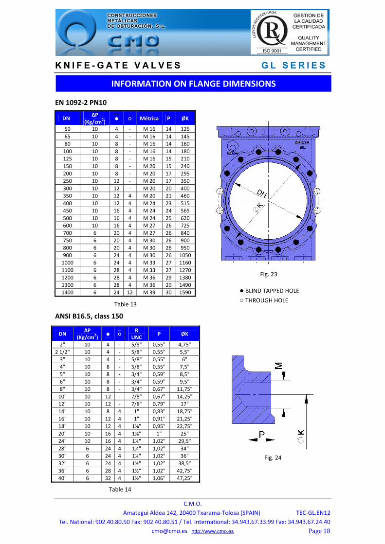
EN 1092‐2 PN10
ANSI B16.5, class 150
DN ΔP
(Kg/cm2) ● o Métrica P ØK
50 10 4 ‐ M 16 14 125
65 10 4 ‐ M 16 14 145
80 10 8 ‐ M 16 14 160
100 10 8 ‐ M 16 14 180
125 10 8 ‐ M 16 15 210
150 10 8 ‐ M 20 15 240
200 10 8 ‐ M 20 17 295
250 10 12 ‐ M 20 17 350
300 10 12 ‐ M 20 20 400
350 10 12 4 M 20 21 460
400 10 12 4 M 24 23 515
450 10 16 4 M 24 24 565
500 10 16 4 M 24 25 620
600 10 16 4 M 27 26 725
700 6 20 4 M 27 26 840
750 6 20 4 M 30 26 900
800 6 20 4 M 30 26 950
900 6 24 4 M 30 26 1050
1000 6 24 4 M 33 27 1160
1100 6 28 4 M 33 27 1270
1200 6 28 4 M 36 29 1380
1300 6 28 4 M 36 29 1490
1400 6 24 12 M 39 30 1590
DN ΔP
(Kg/cm2) ● o
R UNC
P ØK
2" 10 4 ‐ 5/8" 0,55" 4,75"
2 1/2" 10 4 ‐ 5/8" 0,55" 5,5"
3" 10 4 ‐ 5/8" 0,55" 6"
4" 10 8 ‐ 5/8" 0,55" 7,5"
5" 10 8 ‐ 3/4" 0,59" 8,5"
6" 10 8 ‐ 3/4" 0,59" 9,5"
8" 10 8 ‐ 3/4" 0,67" 11,75"
10" 10 12 ‐ 7/8" 0,67" 14,25"
12" 10 12 ‐ 7/8" 0,79" 17"
14" 10 8 4 1" 0,83" 18,75"
16" 10 12 4 1" 0,91" 21,25"
18" 10 12 4 1⅛" 0,95" 22,75"
20" 10 16 4 1⅛" 1" 25"
24" 10 16 4 1¼" 1,02" 29,5"
28" 6 24 4 1¼" 1,02" 34"
30" 6 24 4 1¼" 1,02" 36"
32" 6 24 4 1½" 1,02" 38,5"
36" 6 28 4 1½" 1,02" 42,75"
40" 6 32 4 1½" 1,06" 47,25"
INFORMATION ON FLANGE DIMENSIONS
● BLIND TAPPED HOLE ○ THROUGH HOLE
Fig. 23
Table 13
Fig. 24
Table 14

K N I F E - G A T E V A L V E S G L S E R I E S
C.M.O.
Amategui Aldea 142, 20400 Txarama‐Tolosa (SPAIN) TEC‐GL.EN12
Tel. National: 902.40.80.50 Fax: 902.40.80.51 / Tel. International: 34.943.67.33.99 Fax: 34.943.67.24.40
[email protected] http://www.cmo.es Page19
VERSION
STANDARD
SECTION A‐A
SECTION B‐B
OPTION 1
K N I F E - G A T E V A L V E S G L S E R I E S
C.M.O.
Amategui Aldea 142, 20400 Txarama‐Tolosa (SPAIN) TEC‐GL.EN12
Tel. National: 902.40.80.50 Fax: 902.40.80.51 / Tel. International: 34.943.67.33.99 Fax: 34.943.67.24.40
[email protected] http://www.cmo.es Page20
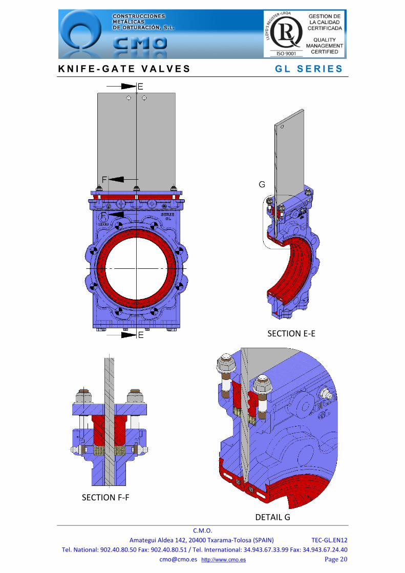
SECTION E‐E
SECTION F‐F
DETAIL G