bifilar determination of earth
TRANSCRIPT

8/3/2019 Bifilar Determination of Earth
http://slidepdf.com/reader/full/bifilar-determination-of-earth 1/9
Bifilar Determination of Earth's
Gravitational Field
Faysal Riaz, Feb 1999
Gravitation | Topics
By experimentation I aim to obtain an accurate value
for the gravitational field strength, g (N kg-1), of the
Earth. I will carry out an experiment using a Bifilar
Pendulum.
The Bifilar Pendulum
I will set a metal rod oscillating by giving it a small angular displacement,(rads),
about the vertical axis when it is fastened onto two strings that are held by corks
firmly clamped onto stands. The motion of the Bifilar Pendulum is Simple Harmonic
Motion, I will prove this later in the report.
The metal rod is uniform and of mass M (kg) and length L (m). The two strings are
of length y (m). I will make sure that both strings are parallel to each other, always
perpendicular to the rotating rod and the same distance from the rod’s centre of
mass (l/2 d metres). The inclination of the strings to the vertical will be given by
(rads).
I will vary the separation of the two strings, d (m), from d » 0.1m to d » 0.7m and
record the time for twenty oscillations of the rod, 20T (s), from this value I will
calculate the periodic time, T (s), ie the time taken for one oscillation.

8/3/2019 Bifilar Determination of Earth
http://slidepdf.com/reader/full/bifilar-determination-of-earth 2/9
The diagram below shows the setup of the experiment:
I will not model the oscillating rod as a particle, instead I will regard it as a system
of connected particles moving in circles of different radii. The same torque applied
to different bodies produces diferent angular accelerations, indicating that each
body has an individual amount of Rotational Inertia that controls the degree ofchange in rotation. The measure of a body’s Rotational Inertia is called Moment of
Inertia. The more difficult it is to change the angular velocity of a body rotating
about a particular axis the greater is its Moment of Inertia about that axis. The
Moment of Inertia of a body is a function of the mass of the body, the distribution
of that mass, that is its size and shape, and the position of the axis of rotation.Therefore these factors must affect the rotational motion of the metal rod.
8/3/2019 Bifilar Determination of Earth
http://slidepdf.com/reader/full/bifilar-determination-of-earth 3/9
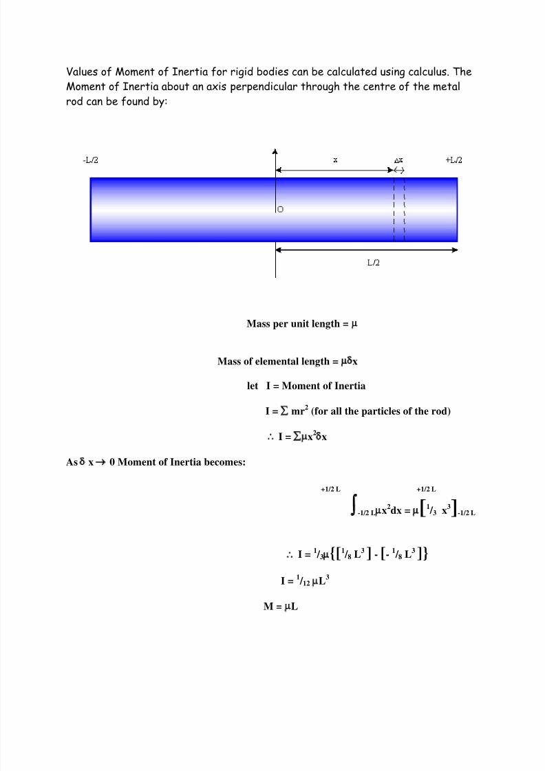
Values of Moment of Inertia for rigid bodies can be calculated using calculus. The
Moment of Inertia about an axis perpendicular through the centre of the metal
rod can be found by:
Mass per unit length =
Mass of elemental length = x
let I = Moment of Inertia
I = mr2 (for all the particles of the rod)
I = x2x
As x 0 Moment of Inertia becomes:
+1/2 L +1/2 L
-1/2 Lx2dx = [1
/ 3 x3]-1/2 L
I =1 / 3{[1
/ 8 L3 ] - [-
1 / 8 L
3 ]}
I =1 / 12 L
3
M = L

8/3/2019 Bifilar Determination of Earth
http://slidepdf.com/reader/full/bifilar-determination-of-earth 4/9
I =1 / 12 ML
2
I will now prove that the motion of the Bifilar Pendulum is in fact Simple Harmonic
Motion.
Vertically the metal rod is in equilibrium so the Tensions of the strings that holdthe rod are given by:
T =1 / 2 Mg
So the Tensions of the strings when they are inclined to the vertical by a (rads),
are given by:
T =1 / 2 MgCos
So the restoring forces, T R, which move the strings back to their original positionsare given by:
TR =1 / 2 MgSin
The angle a (rads) is very small so the restoring forces become:
TR =1 / 2 Mg
Since both the angle of inclination to the vertical of the strings, a (rads), and the
angular displacement of the metal rod, q (rads), are very small and then:
y =1 / 2d
= d
2y
TR = Mgd 4y
Therefore the restoring Couple, CR, which acts towards the equilibrium position so
is negative, is given by:
CR = -Mgd2
4y
Applying Newton’s Second Law for the rotational motion of the rod, which is of
constant mass:

8/3/2019 Bifilar Determination of Earth
http://slidepdf.com/reader/full/bifilar-determination-of-earth 5/9
Id2= -Mgd
2
dt2
4y
d2= -Mgd
2
dt2
4Iy
This equation is in the form of the standard equation for Simple Harmonic Motion,
which is shown below, therefore the motion of the Bifilar Pendulum is simple
Harmonic motion:
a = -2s
2= Mgd
2
4Iy
So because the motion of the metal rod is Simple Harmonic Motion its Time Period,T (s), is given by:
T = 2
T = 24Iy
Mgd2
I = MgT2d
2
162y
The Moment of Inertia of the metal rod, as I have previously proven, can also begiven by the following equation:
I =1 / 12 ML
2
ML2
= MgT2d
2
12 162y
T2
= 42L
2y
3g d2
T d
let k2
= 42L
2y
3g

8/3/2019 Bifilar Determination of Earth
http://slidepdf.com/reader/full/bifilar-determination-of-earth 6/9
T = k
d
This equation is in the form of y = mx + c, so if I plot T (s) against d-1 (m-1) I will
obtain a straight line graph through the origin, whose gradient will be found by:
Gradient = y
x
Gradient = T = Td d
-1
Gradient = k
So when I have a value for k (ms) I will use it to find the gravitational field
strength, g (N kg-1), of the Earth as shown below:
g = 42L
2y
3k2
Results
String Separation Time for 20 Oscillations Periodic Time d-1
d (m) 20T (s) T (s) (m-1)
0.164 65.58 3.29 6.10
0.212 50.79 2.53 4.72
0.316 33.59 1.68 3.16
0.399 27.22 1.36 2.50
0.501 21.78 1.06 2.00
0.620 7.26 0.84 1.61

8/3/2019 Bifilar Determination of Earth
http://slidepdf.com/reader/full/bifilar-determination-of-earth 7/9
The graph below shows the results for the Bifilar Pendulum experiment:
Now I am able to calculate a value for gravity using the above graph:
Gradient = 3.5 = 0.53 ms 6.6
g = 42L
2y
3k2
k2
= 0.532
m2s
2
L2
= 0.6622
m2
y = 0.478 m
g = 9.80 N kg-1
Conclusion

8/3/2019 Bifilar Determination of Earth
http://slidepdf.com/reader/full/bifilar-determination-of-earth 8/9
By experimentation I have obtained an accurate value for the gravitational field
strength, g (N kg-1), of the Earth. The value of gravity that I have obtained from
the Bifilar Pendulum experiment is 9.80 N kg-1. The value of gravity that I have
obtained from the light gates experiment is 9.77 N kg-1.
Taking into consideration England's latitude and longitude, our distance from the
Earth’s centre of mass and the effects of the rotation of the Earth the
approximate value of gravity in England is 9.8143 N kg-1.
So the percentage error in the Bifilar Pendulum experiment is:
Percentage Error = 9.81 - 9.80 x 100%
9.81
Percentage Error = 0.12 % However this limited the experiment because if the angular displacement, (rads),
was large, that is over 0.175 rads or 10° , then the motion of the Bifilar Pendulum
was no longer Simple Harmonic Motion. So if this occurred the Time Period, T (s),
formula sown below would no longer be valid for the motion of the metal rod:
T = 24Iy
Mgd2
If this occurred it would have definitely caused a significant error in the results
for this experiment because from the above formulae the gravitational fieldstrength, g (N kg-1), of the Earth was calculated.
The lengths of the two strings may not have been the same, or they may not have
been the same distance from the centre of mass of the metal rod (1/2 d metres),
so the rod may have been slightly slanted. Therefore the position of the axis of
rotation of the rod was not perpendicular through the centre of the rod, this
means that its Moment of Inertia is not exactly given by the formula shown below:
I =
1
/ 12 ML
2
This may have caused the slight error in the result of this experiment.
If the metal rod that was used was not a uniform rod (of uniform density) then its
centre of mass may not have been at the axis of rotation, which was perpendicular
through the centre of the rod. Therefore the Moment of Inertia may not exactly

8/3/2019 Bifilar Determination of Earth
http://slidepdf.com/reader/full/bifilar-determination-of-earth 9/9
be given by the formula shown above. This may have caused the slight error in the
result of this experiment.
The error in this experiment may have been caused by the incorrect measurement
of the length of the metal rod, L (m), the string separation, d (m), the string
length, y (m), or of the time for twenty oscillations, 20T (s). A faulty stopwatch or
human error may have caused this.
I hope you have found this page useful.
Back To The Top