bifurcation synthesis by means of harmonic …amsacta.unibo.it/509/1/g_13_02.pdf · g.leuzzi, f. di...
TRANSCRIPT
G.Leuzzi, F. Di Paolo: Bifurcation Synthesis by means of Harmonic Balance and Conversion Matrix. EuMW 2003 – GAAS, session G13 – 6,7 October
1
Bifurcation Synthesis by means of Harmonic Balance and Conversion Matrix
GIORGIO LEUZZI, MEMBER, IEEE, AND FRANCO DI PAOLO, MEMBER, IEEE
Abstract- In this paper a new bifurcation synthesis procedure is described. Its foundations are built on an extension of the Conversion Matrix concept, applied to the nonlinear sub network of the circuit simulated through Harmonic Balance. The Cross-frequency Stability Curves (CSC) are defined, which are the nonlinear equivalent of the Stability Circles valid for linear networks. The CSC gives us regions of reflection coefficient values for the loads that yield potential period doubling in the circuit. The proposed synthesis method can be used within any simulation program based on the Harmonic Balance algorithm, allowing the designer the possibility to check the nonlinear stability of any simulated circuit, or to design intentionally unstable circuits. Results of the CSC method are given for a GaAs FET circuit synthesized to operate as a divider-by-two.
I. INTRODUCTION
The most general and rigorous method to analyze nonlinear circuits is, of course, the mathematical approach. The circuit is transformed in a System of Nonlinear Ordinary Differential Equations, whose solutions are then investigated. From a CAD point of view, the fastest and cost-effective approach is the Harmonic Balance (HB) solving technique. Unfortunately, HB CAD programs do not actually allow the direct synthesis of nonlinear circuits, and the study of this possibility is still an open issue.
Generally speaking, it is known that non-linear circuits can exhibit solutions that are not periodic, and/or present period doubling for some circuit values. The period doubling is graphically represented by a bifurcation of the graph of the measured electrical quantity, usually a current or voltage, vs. a parameter which is responsible for the bifurcation. When a division-by-2 of the period occurs, it is common practice to refer to it as a bifurcation. In the following, we will indicate with N the division factor: so, N=2 means a division-by-2, and so on. Famous circuit examples are Chua’s circuit [1] and Van der Pol's oscillator [2], extensively analyzed for the complexity of their solutions, that include period doubling and chaotic behavior.
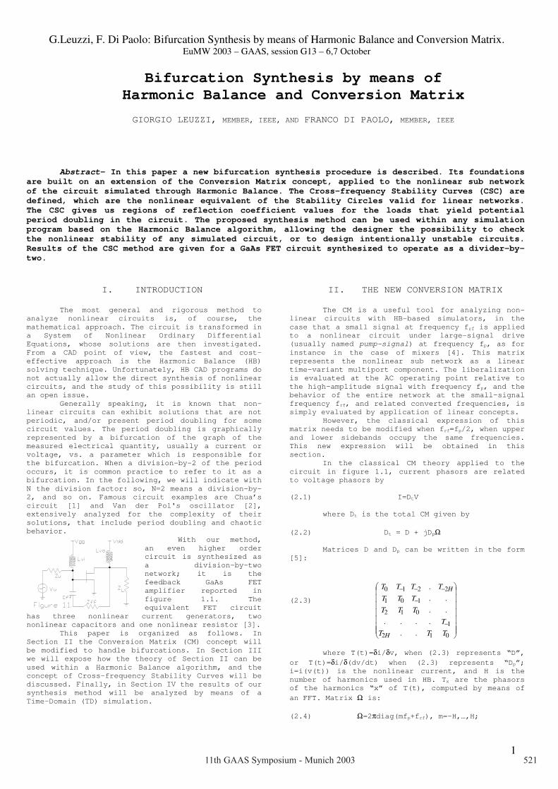
With our method, an even higher order circuit is synthesized as a division-by-two network; it is the feedback GaAs FET amplifier reported in figure 1.1. The equivalent FET circuit
has three nonlinear current generators, two nonlinear capacitors and one nonlinear resistor [3].
This paper is organized as follows. In Section II the Conversion Matrix (CM) concept will be modified to handle bifurcations. In Section III we will expose how the theory of Section II can be used within a Harmonic Balance algorithm, and the concept of Cross-frequency Stability Curves will be discussed. Finally, in Section IV the results of our synthesis method will be analyzed by means of a Time-Domain (TD) simulation.
II. THE NEW CONVERSION MATRIX The CM is a useful tool for analyzing non-
linear circuits with HB-based simulators, in the case that a small signal at frequency frf is applied to a nonlinear circuit under large-signal drive (usually named pump-signal) at frequency fp, as for instance in the case of mixers [4]. This matrix represents the nonlinear sub network as a linear time-variant multiport component. The liberalization is evaluated at the AC operating point relative to the high-amplitude signal with frequency fp, and the behavior of the entire network at the small-signal frequency frf, and related converted frequencies, is simply evaluated by application of linear concepts.
However, the classical expression of this matrix needs to be modified when frf=fp/2, when upper and lower sidebands occupy the same frequencies. This new expression will be obtained in this section.
In the classical CM theory applied to the circuit in figure 1.1, current phasors are related to voltage phasors by
(2.1) I=DtV
where Dt is the total CM given by
(2.2) Dt = D + jDpΩ Matrices D and Dp can be written in the form
[5]:
(2.3) where T(t)=δi/δv, when (2.3) represents “D”,
or T(t)=δi/δ(dv/dt) when (2.3) represents “Dp”; i=i(v(t)) is the nonlinear current, and H is the number of harmonics used in HB. Tx are the phasors of the harmonics “x” of T(t), computed by means of
an FFT. Matrix Ω is:
(2.4) Ω=2πdiag(mfp+frf), m=-H,…,H;
−
−
−−−
012
1
012
101
2210
......
..
..
.
TTT
T
TTT
TTT
TTTT
H
H
11th GAAS Symposium - Munich 2003 521

G.Leuzzi, F. Di Paolo: Bifurcation Synthesis by means of Harmonic Balance and Conversion Matrix. EuMW 2003 – GAAS, session G13 – 6,7 October
2
It is possible to show that for N=2 the equation (2.1) becomes [6]:
(2.5)
where the complex-valued matrices Ga, Gb, Ca,
Cb and M have dimension P(H+1)xP(H+1); “P” is the number of the ports connecting the linear and nonlinear sub networks of the circuit. The matrices in (2.5) are:
(2.6) As pointed out above, the use of (2.1)…(2.3)
for frf=fp/2 gives wrong results for sidebands levels, and our expression (2.5) should be used. This is because the USB at frequencies nfp+frf coincide with LSB at frequencies (n+1)fp-frf; consequently, also the corresponding ports of the CM coincide. Results are therefore not meaningful when using (2.1)…(2.3) to analyze dividers by two.
In the next sections we will describe how the new CM equation (2.5) allows the synthesis of a bifurcation for the circuit in figure 1.1.
III. REDUCTION OF THE MODIFIED CM The CM can be easily implemented within any
HB program, since its elements are simply obtained by derivation with respect to voltage from the current functional expressions of the nonlinear elements as functions of the voltage. This last operation is always performed within an HB analysis code, and therefore CM evaluation is only a matter of suitable programming.
We note explicitly that the CM represents a linear multiport network, relating signals at frequencies nfp±frf; the signals are frequency-converted between the different ports (frequencies) by the time-variant linear network that is the linearized nonlinear device driven by a large signal.
The use of CM as an analysis method to investigate nonlinear stability is well established [4], although not many applications are reported. The authors have already used the classical CM to synthesize the frequency division of a microwave FET circuit with N=3 [7], while the synthesis for N=2 requires the use of (2.5).
Our synthesis procedure requires the calculation at a meaningful port (i.e. frequency) of the CM of a quantity equivalent to the reflection coefficient of a classical time-invariant linear network. This implies the reduction of the CM to a one-port expression, by means of reduction formulae. We will evaluate the wave “b” reflected at this port that, due to (2.5), is a function of both amplitude and phase of the incoming wave “a” at the same port.
The CM reduction procedure applied to (2.5) cannot be executed with the usual technique with
complex numbers, since in (2.5) there is an operation of complex conjugation. So, the form of (2.5) mandates the transformation of this expression into an equivalent one, in terms of real numbers, i.e. real and imaginary parts of voltages and currents. To this purpose, let us indicate with “a” and “b” the generic element of Ya and Yb, and with subscript “r” and “j” its real and imaginary part; it is possible to show that (2.5) rewrites as
(3.1) IR=(α+β)VR=J2HVR
where
(3.2)
(3.3)
(3.4) Now we have to reduce matrix J2L to a 2x2
real-valued matrix, which will represent the original multiport circuit reduced to a single port by loading the other (H-1) ports. The reduction procedure is an iterative process, which we will describe for a 4x4 matrix J2H, corresponding to a 2-port network. Then, (3.1) becomes
(3.5)
Now, terminating port 1 with the load admittance YL1, i.e. the load admittance at the frequency of port 1 (fig. 3.1), real and imaginary parts of the current phasor at port 0 are
(3.6) where
(3.7) Equation (3.6) is the reduced expression of
(3.5). It can be iterated for a J2H matrix of any
•−•−−
••••••••
−•−−•
−•−−
=
rHHjHHrHjHrHjH
jHHrHHjHrHjHrH
HrHjrjrj
HjHrjrjr
HrHjrjrj
HjHrjrjr
aaaaaa
aaaaaa
aaaaaa
aaaaaa
aaaaaa
aaaaaa
1100
1100
1111111010
1111111010
0001010000
0001010000
α
−•−−•
•••••••−•−−
•−•−−
•
=
rHHjHHrHjHrHjH
jHHrHHjHrHjHrH
HrHjrjrj
HjHrjrjr
HrHjrjrj
HjHrjrjr
bbbbbbbbbbbb
bbbbbb
bbbbbbbbbbbb
bbbbbb
1100
1100
1111111010
1111111010
0001010000
0001010000
β
=
j
r
j
r
j
r
j
r
v
v
v
v
yyyy
yyyy
yyyyyyyy
i
i
i
i
1
1
0
0
33323130
23222120
13121110
03020100
1
1
0
0
[ ]Wyyyy
yy
yy
rLjL
jLrL =
−
−−
3332
2322
11
11
•=
jH
r
j
r
R
v
v
v
v
V 1
0
0
•=
jH
r
j
r
R
i
i
i
i
I 1
0
0
[ ]
=
+
=
−j
rt
j
r
j
rv
vY
v
v
yy
yyW
yy
yy
yy
yyi
i
0
0
0
0
3130
21201
1312
0302
1110
0100
0
0 ][
**
*
*1
*0
121
232
1211
0
0
101
10
*
*1
*0
121
232
121
1
0
0
101
10
1
0
)()(
212
5.1
5.0
212
5.15.0
VYVYVMCjGVMCjG
vH
v
v
cc
ccc
ccc
j
vH
v
v
cc
ccc
ccc
j
v
v
v
gg
ggg
ggg
v
v
v
gg
ggg
ggg
i
i
i
I
babpbapa
HHH
H
H
p
HH
H
H
p
HHH
H
H
HH
H
H
H
+=−++=
=
+•
••••••
••
−
+•
••••••
••
+
+
•
••••••
••
+
•
••••••
••
=
•=
++
+
+
+−
−−
++
+
+
+−
−−
ωω
ωω
+•••••
•••
=
••••••
••
=
••••••
••
=
••••••
••
=
••••••
••
=
++
+
+
+−
−−
++
+
+
+−
−−
2/)12(00
02/3002/1
121
232
121
0
101
10
121
232
121
0
101
10
H
M
cc
cccccc
C
cc
ccc
ccc
C
gg
gggggg
G
gg
ggg
ggg
G
HH
H
H
b
H
H
H
a
HH
H
H
b
H
H
H
a
11th GAAS Symposium - Munich 2003522

G.Leuzzi, F. Di Paolo: Bifurcation Synthesis by means of Harmonic Balance and Conversion Matrix. EuMW 2003 – GAAS, session G13 – 6,7 October
3
dimension, port after port, allowing the reduction to one port of the real-valued matrix.
IV. BIFURCATION SYNTHESIS First of all the circuit in fig.1.1 is
analyzed by means of a HB analysis; at this stage, the values of the load networks must be specified at the HB frequencies nfp only. Then, the CM is computed with expression of this matrix needs to be modified when frf=fp/2. Expression (3.6) is obtained from the CM by specifying the loads at all frequencies except that used for the synthesis of the bifurcation, and the 2x2 Yt matrix is transformed into a scattering 2x2 matrix, using well-known transformations formulae [8]. So, let us rewrite equation (3.6) into a reflection coefficient-like expression as
(4.1) where br, bj, ar and aj are the real and
imaginary parts of the reflected wave “b” and incident wave “a”. We have one of the following possibilities:
1) |b|<|a|: the circuit is stable,
and a bifurcation will not occur 2) |b|=|a|: the circuit is in a
critic operation point; small variations of the elements values can generate or suppress the bifurcation
3) |b|>|a|: the circuit can give
raise to a bifurcation
Note that the four elements inside the 2x2 matrix in (4.1) are in general all different from to one another. Therefore, the reflected wave will draw an ellipse in the complex plane, when the incident wave is unitary with arbitrary phase. Then, in case 3) the ellipse intersects the unit circle, and there will be some values of the phase of the incident wave “a” for which |b|>|a|, while it may happen that for other values |b|<|a|. Since the incident wave is a noise or perturbation, it can have any phase value; therefore, in case 3) an instability can arise.
We now synthesize the load that will generate the instability. We compute the phase difference ∆ϕ=arg(b)-arg(a) between the reflected and the incident waves, for the phase of the incident wave “a” corresponding to the maximum value of |b| along the ellipse. The Barkhausen criterion is fulfilled if:
(4.2) γL=|b|-1exp(j∆ϕ) with ∆ϕ=arg(b)-arg(a) corresponding to a load impedance ZL:
(4.3) ZL=-Z0 (γL*+1)/(γL*-1) This value of ZL must be assumed by the load
network at the frequency of the port considered for the synthesis, while the network shall keep the same values at the HB frequencies it assumes in the HB analysis. However, we have verified that this requirement can be partially relaxed, and in practice it is sufficient that it be verified for the first two or three harmonics of fp.
As an example, in figure 4.1 the ellipses are drawn for the circuit in figure 1.1, with a stimulus at fp=2GHz and amplitude of 2.5V. Then the load is synthesized as reported in (4.2) and (4.3), and a TD simulation is performed for verification of
the onset of the instability. The resulting spectrum of the drain voltage
is indicated in figure 4.2 where the bifurcation at frf=1GHz is evident.
Great help for bifurcation synthesis can also be obtained from graphs like that in figure 4.3. This graph has been obtained using the proposed
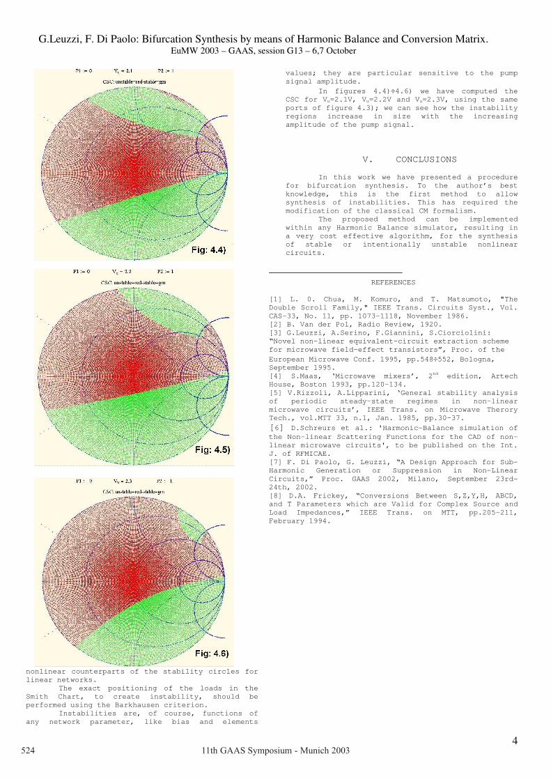
method, reducing the nonlinear network to a 2 port and sweeping on the Smith Chart the loads at output port; the pump signal for this figure is a voltage source of Vu=2.4V and frequency fp=2GHz. In particular, we have reported in green and red the load values at output port, at frf/2, which give at input port, at frf/2, respectively stability (green) and instability (red). These curves represent the
Γ=
=
j
rt
j
r
rj
jr
j
ra
a
a
a
b
b][
1110
0100γγγγ
11th GAAS Symposium - Munich 2003 523
G.Leuzzi, F. Di Paolo: Bifurcation Synthesis by means of Harmonic Balance and Conversion Matrix. EuMW 2003 – GAAS, session G13 – 6,7 October
4
nonlinear counterparts of the stability circles for linear networks.
The exact positioning of the loads in the Smith Chart, to create instability, should be performed using the Barkhausen criterion.
Instabilities are, of course, functions of any network parameter, like bias and elements
values; they are particular sensitive to the pump signal amplitude.
In figures 4.4)÷4.6) we have computed the CSC for Vu=2.1V, Vu=2.2V and Vu=2.3V, using the same ports of figure 4.3); we can see how the instability regions increase in size with the increasing amplitude of the pump signal.
V. CONCLUSIONS
In this work we have presented a procedure for bifurcation synthesis. To the author’s best knowledge, this is the first method to allow synthesis of instabilities. This has required the modification of the classical CM formalism.
The proposed method can be implemented within any Harmonic Balance simulator, resulting in a very cost effective algorithm, for the synthesis of stable or intentionally unstable nonlinear circuits.
REFERENCES
[1] L. 0. Chua, M. Komuro, and T. Matsumoto, "The Double Scroll Family," IEEE Trans. Circuits Syst., Vol. CAS-33, No. 11, pp. 1073-1118, November 1986. [2] B. Van der Pol, Radio Review, 1920. [3] G.Leuzzi, A.Serino, F.Giannini, S.Ciorciolini: “Novel non-linear equivalent-circuit extraction scheme for microwave field-effect transistors”, Proc. of the European Microwave Conf. 1995, pp.548÷552, Bologna, September 1995. [4] S.Maas, ‘Microwave mixers’, 2nd edition, Artech House, Boston 1993, pp.120-134. [5] V.Rizzoli, A.Lipparini, ‘General stability analysis of periodic steady-state regimes in non-linear microwave circuits’, IEEE Trans. on Microwave Therory Tech., vol.MTT 33, n.1, Jan. 1985, pp.30-37.
[6] D.Schreurs et al.: 'Harmonic-Balance simulation of the Non-linear Scattering Functions for the CAD of non-linear microwave circuits', to be published on the Int. J. of RFMICAE. [7] F. Di Paolo, G. Leuzzi, “A Design Approach for Sub-Harmonic Generation or Suppression in Non-Linear Circuits,” Proc. GAAS 2002, Milano, September 23rd-24th, 2002. [8] D.A. Frickey, “Conversions Between S,Z,Y,H, ABCD, and T Parameters which are Valid for Complex Source and Load Impedances,” IEEE Trans. on MTT, pp.205-211, February 1994.
11th GAAS Symposium - Munich 2003524