big physicsday for in2p3 · flexrio device. timestamps provided by ieee1588-2008 • epics is the...
TRANSCRIPT

ni.com
Big Physics Day for IN2P316/10/2017
NI CONFIDENTIAL

ni.com
Control, Diagnostic and Measurement for Physics Systems
and Experiments
3ni.com
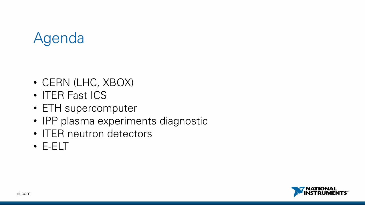
Agenda
• CERN (LHC, XBOX)• ITER Fast ICS• ETH supercomputer• IPP plasma experiments diagnostic• ITER neutron detectors• E-ELT

4ni.com
CERN – Usage of NI within the facility
• Number of LabVIEW users on site - +500
• CERN staffed support team - 16
• Regular training class held - 10 Classes
• LabVIEW proficiency (onsite) - CLAD, CLD, CLA
• Some projects:
• Collimators :- https://youtu.be/MjHals9hDz0
• Xbox [1,2,3] – Klystron controllers
• Magnet Safety Systems
• ….
CMS Detector
1 Collimator Control Systems
Collimator Test Bench
5ni.com
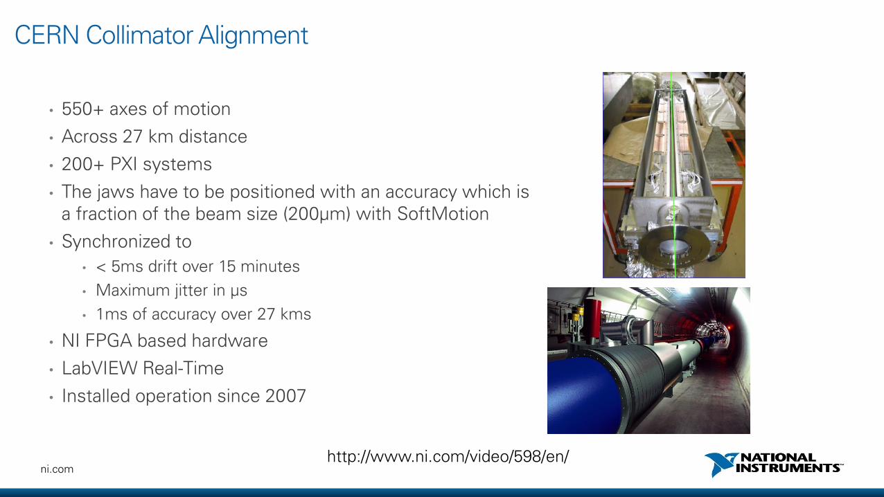
CERN Collimator Alignment
• 550+ axes of motion
• Across 27 km distance
• 200+ PXI systems
• The jaws have to be positioned with an accuracy which is a fraction of the beam size (200μm) with SoftMotion
• Synchronized to
• < 5ms drift over 15 minutes
• Maximum jitter in μs
• 1ms of accuracy over 27 kms
• NI FPGA based hardware
• LabVIEW Real-Time
• Installed operation since 2007
http://www.ni.com/video/598/en/
6ni.com
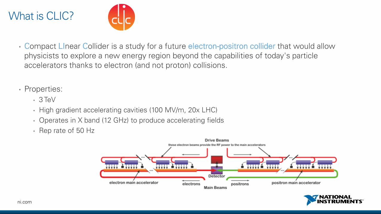
What is CLIC?
• Compact LInear Collider is a study for a future electron-positron collider that would allow physicists to explore a new energy region beyond the capabilities of today's particle accelerators thanks to electron (and not proton) collisions.
• Properties:
• 3 TeV
• High gradient accelerating cavities (100 MV/m, 20x LHC)
• Operates in X band (12 GHz) to produce accelerating fields
• Rep rate of 50 Hz

7ni.com
CERN – XBOX Control and Test System
Experimental physicists in the Beams RF group at CERN teamed up with NI over the past three years to develop 3 generations of high-gradient accelerating cavities conditioning and testing systems.
Project has received worldwide attention and system duplications were ordered by:• SLAC• Uppsala University• Uni Valencia
XBOX 1 - PXIe control with mixture of NI and external instrumentationXBOX 2 - Fully PXIe-based control and instrumentationXBOX 3 - Same as 2, but can test multiple structures simultaneously
Hardware• PXIe-1075, PXIe-8135• FlexRIO 5761R, 5772R,
6583R, 5793R
ResultsXBOX 1 & 2 are fully functional and have delivered thousands of hours worth of data. XBOX 3 is currently being assembled and tested.The collaboration has allowed the CLIC project to gather results quickly and in a flexible way by being able to reprogram the system as required by the project.
ni.com
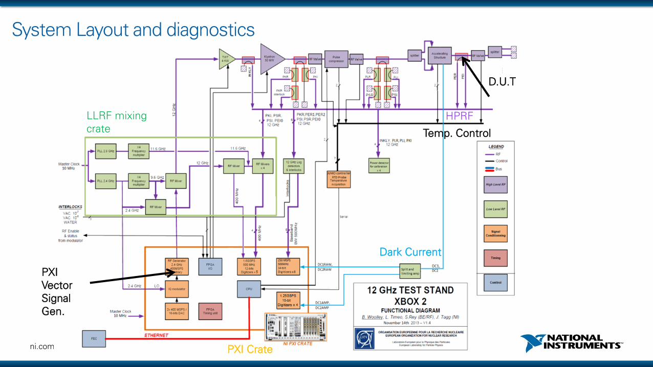
System Layout and diagnostics
LLRF mixing crate
D.U.T
HPRF
PXI Vector Signal Gen.
Temp. Control
Dark Current
PXI Crate

9ni.com
XBOX 2 software Architecture
RFAcquisition
Analysis
LogBreakdown
MonitoringAcquisition
AggregateData
LogTrend Data
Interlocks
Timing
Message Handler
RFGeneration
RF Pulse Control
Error Handler
InterlocksAcquisition
Engine
GUI
Errors
Cmds
Properties
FPGA
Real-time
Windows
queueexternal
latest valueconfiguration / commands

10ni.com
ITER Interlock Systems
ITER Interlocks are implemented at :
- a plant system level by the Plant Interlock Systems or PIS
- a central level by the Central Interlock System or CIS
Slow interlocks are based on Siemens PLC
Fast interlocks are based on FPGA redundant technologies.
Highly critical interlocks are based on hardwired current loops
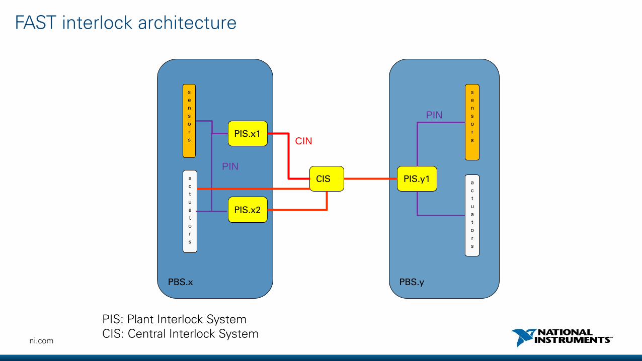
11ni.com
PBS.x PBS.y
CIS
PIS.x1
PIS.y1
PIS.x2
s
e
n
s
o
r
s
a
c
t
u
a
t
o
r
s
s
e
n
s
o
r
s
a
c
t
u
a
t
o
r
s
CIN
PIN
PIN
FAST interlock architecture
PIS: Plant Interlock SystemCIS: Central Interlock System
12ni.com
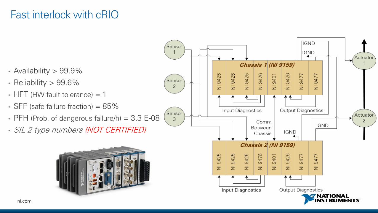
• Availability > 99.9%
• Reliability > 99.6%
• HFT (HW fault tolerance) = 1
• SFF (safe failure fraction) = 85%
• PFH (Prob. of dangerous failure/h) = 3.3 E-08
• SIL 2 type numbers (NOT CERTIFIED)
Fast interlock with cRIO
13ni.com
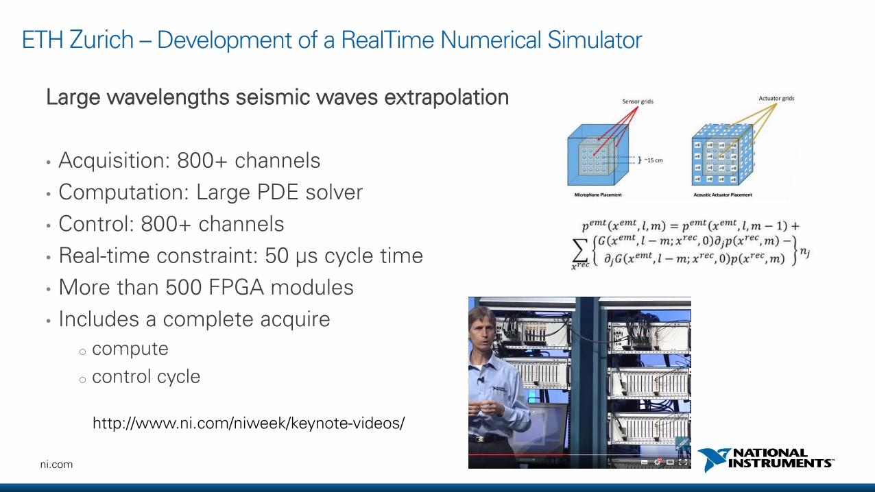
ETH Zurich – Development of a RealTime Numerical Simulator
Large wavelengths seismic waves extrapolation
• Acquisition: 800+ channels
• Computation: Large PDE solver
• Control: 800+ channels
• Real-time constraint: 50 µs cycle time
• More than 500 FPGA modules
• Includes a complete acquire
o compute
o control cycle
http://www.ni.com/niweek/keynote-videos/

14ni.com
Czech Institute of Plasma Physics
• Thomson scattering system for plasma
temperature and density diagnostic
• Synchronized high speed data acquisition
• 120 channels running at 1GS/s
• Tight synchronization over 4 PXI chassis
• Skew < 500 ps
• 30Hz repetition rate
http://sine.ni.com/cs/app/doc/p/id/cs-13319#

15ni.com
ITER Neutron detectors
• ITER has established the use of 4 FC units, each having 3 individual detectors
Figures taken from (M. ISHIKAWA, et al., 2008)
• ITER
• Magnetic confinement of plasma by control system (CODAC)
• Diagnostics
• Provides information to the Plasma Control System, and post-pulse analysis
• Fusion power measurement is one of them.
• A fraction of the fusion reaction generates neutrons.
• Fission Chamber (FC) is based on the neutron diagnostics (temporal resolution restricted to 1 ms for counting, campbelling, and current measurements)
16ni.com
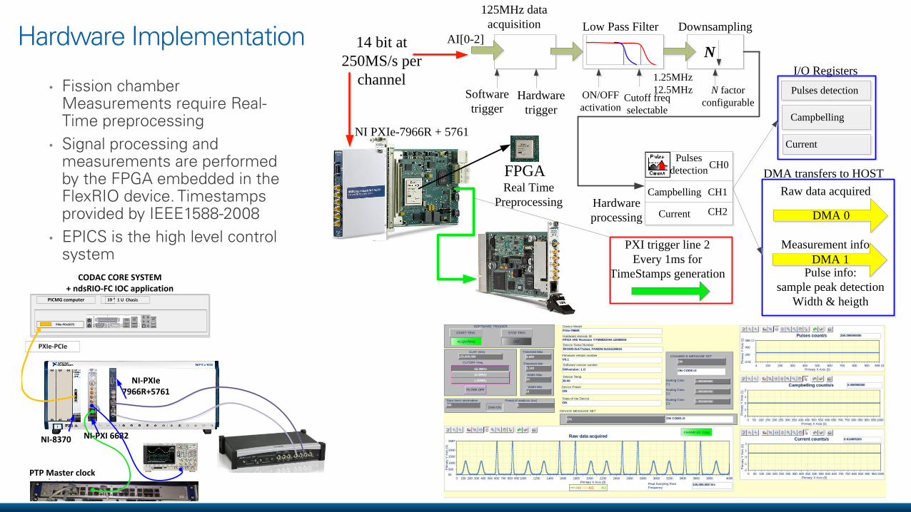
Hardware Implementation
• Fission chamber Measurements require Real-Time preprocessing
• Signal processing and measurements are performed by the FPGA embedded in the FlexRIO device. Timestamps provided by IEEE1588-2008
• EPICS is the high level control system
FPGA Real Time
Preprocessing
NI PXIe-7966R + 5761
125MHz data
acquisition
Software
triggerHardware
trigger
AI[0-2] Low Pass Filter
ON/OFF
activationCutoff freq
selectable
1.25MHz
12.5MHz
Downsampling
N factor
configurable
N
Pulses
detection
Campbelling
Current
CH0
CH1
CH2Hardware
processing
DMA transfers to HOST
Measurement info.
Pulse info:
sample peak detection
Width & heigth
Raw data acquired
DMA 1
DMA 0
I/O Registers
Pulses detection
Campbelling
Current
PXI trigger line 2
Every 1ms for
TimeStamps generation
14 bit at
250MS/s per
channel
PICMG computer 19 ” 1 U Chasis
PXIe-PCIe8372
PXIe-PCIe
NI-8370
CODAC CORE SYSTEM+ ndsRIO-FC IOC application
NI-PXIe 7966R+5761
PTP Master clock
NI-PXI 6682
17ni.com
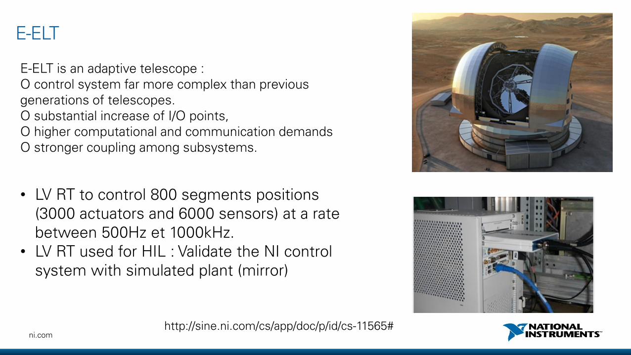
E-ELT
E-ELT is an adaptive telescope : O control system far more complex than previous generations of telescopes.O substantial increase of I/O points,O higher computational and communication demandsO stronger coupling among subsystems.
http://sine.ni.com/cs/app/doc/p/id/cs-11565#
• LV RT to control 800 segments positions (3000 actuators and 6000 sensors) at a rate between 500Hz et 1000kHz.
• LV RT used for HIL : Validate the NI control system with simulated plant (mirror)

ni.com
How to interface NI products to EPICS

19ni.com
Agenda
• Main EPICS concepts• NI-EPICS interface options

20ni.com
Commercial
Instruments
IOCIOC
IOC
IOCCAS
CAS
Custom
hardware
Technical
Equipment
Ou
tpu
t
Inp
ut
Client SoftwareCSS
ALH StripToolTCL/TK
Perl Scripts
OAG Apps
Many, many
others …
LabVIEW
Channel Access
CA Server Software EPICS Database
consists of Process Variables
Custom
Programs
Realtime control
Sequence
Programs
Records
EPICS architecture
Ou
tpu
t
From PSI Epics Course
Network based Client/Server control system architecture Servers provide information and service/ Clients request information or use services
What is needed?- An EPICS Base- A database- An EPICS
driver- A client

21ni.com
Sequencer
LAN (Network)
Device Support
I/O Hardware
The major software components of an IOC
Database
Channel Access
Inside an IOC

ni.com
Hardware
Driver
Device Support
Register accessDriver API functions
Device supportfunction table
The "glue"
Does not know about records
Record specific
Driver specific
Hardware specific
RecordsDoes not know about drivers
Device support and records record (ai, “Room_Temperature")
field (EGU, “°C")
field (LOW, “10")
field (HIGH, “40")
field (HOPR, “50")
field (LOPR, "0")
field (DESC, “Room A temp")
field (DTYP, “NI 6268 ")
field (INP, "#C0 S0)
EPICS process variables (HW config, HW I/Os, calculations …)
field (SCAN, “1 Second”)

23ni.com
• Record processing can be periodic or event driven or passive
• Periodic: • Standard scan rates: 10, 5, 2, 1, 0.5, 0.2 and 0.1 seconds
• Custom scan rates can be configured up to speeds allowed by operating system and hardware
• Event driven:• Hardware interrupts
• EPICS Events (post_event)
• Passive:• Channel Access Puts (caput)
• Request from another record via links
Records processing
24ni.com
EP
ICS
IO
C S
erv
er
Sequencer
LAN (Network)
Custom Device Support
I/O Hardware
Database
Channel Access
Soft Application (LabVIEW, C…)
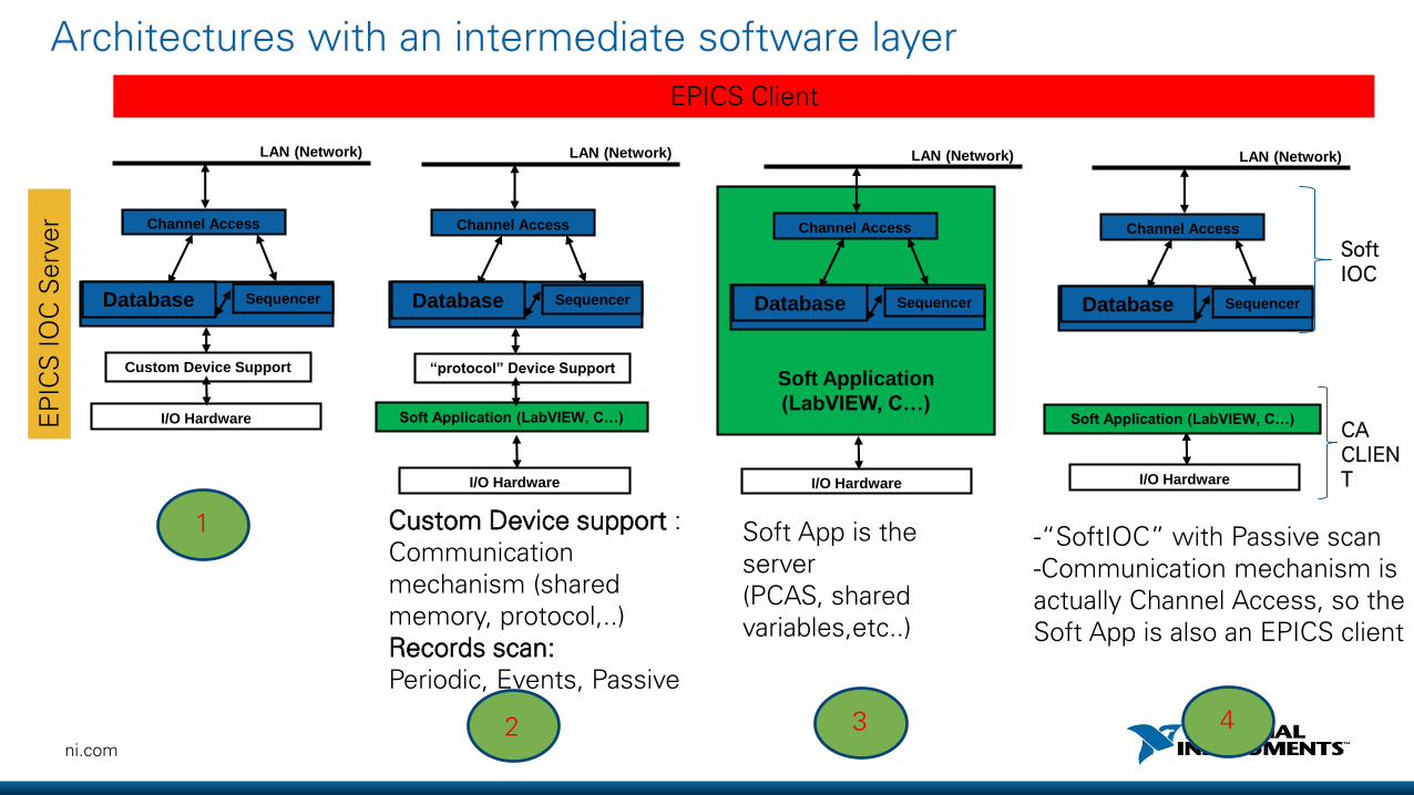
Custom Device support : Communication mechanism (shared memory, protocol,..)Records scan:Periodic, Events, Passive
-“SoftIOC” with Passive scan-Communication mechanism is actually Channel Access, so the Soft App is also an EPICS client
EPICS Client
Architectures with an intermediate software layer
Sequencer
LAN (Network)
“protocol” Device Support
I/O Hardware
Database
Channel Access
Soft Application
(LabVIEW, C…)
Sequencer
LAN (Network)
I/O Hardware
Database
Channel Access
Soft App is the server(PCAS, shared variables,etc..)
Soft Application (LabVIEW, C…)
Sequencer
LAN (Network)
I/O Hardware
Database
Channel Access
Soft IOC
CACLIENT
1
2 3 4

25ni.com
EPICS-NI interface

26ni.com
NI Platforms• Rugged form factor with a processor and a reconfigurable FPGA• Real-Time OS (VxWorks, Linux RT)• Designed for harsh environments (temperature, shocks, passive cooling,
etc..)• High density hot swappable I/O modules, with built-in conditioning• Advanced control, signal processing, modular prototyping, etc…
• PCI/PCIe extended form factor with built-in timing and synchronization• Windows/Linux/Real-Time embedded/remote controllers• Until 24GB/s of system throughput, 8GB/s per slot, 3.6 GB/s storage speed• More than 600 NI instruments (DAQ, digitizers, multimeters, generators,
power supplies, switching, RF analyzers and generators, industrial buses…)
NI CompactRIO
PXIe
27ni.com
CSS EPICS client
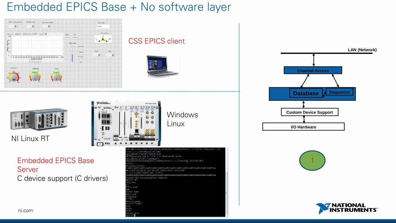
Embedded EPICS Base Server C device support (C drivers)
Embedded EPICS Base + No software layer
Sequencer
LAN (Network)
Custom Device Support
I/O Hardware
Database
Channel Access
1
NI Linux RT
WindowsLinux
28ni.com
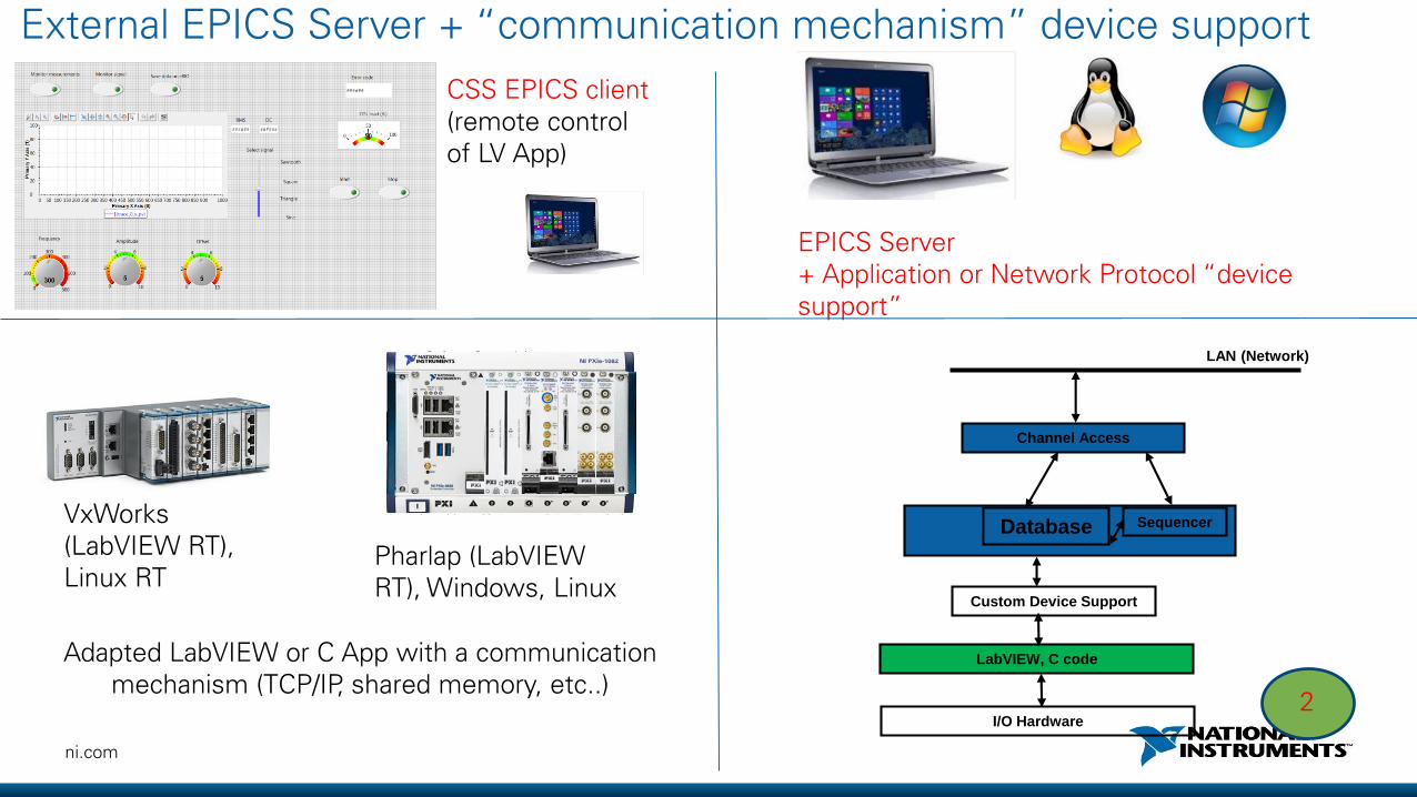
EPICS Server+ Application or Network Protocol “device support”
CSS EPICS client (remote control of LV App)
Adapted LabVIEW or C App with a communication mechanism (TCP/IP, shared memory, etc..)
External EPICS Server + “communication mechanism” device support
Sequencer
LAN (Network)
Custom Device Support
LabVIEW, C code
Database
Channel Access
I/O Hardware2
VxWorks (LabVIEW RT), Linux RT
Pharlap (LabVIEW RT), Windows, Linux
29ni.com
CSS EPICS client (remote control of LV RT App)
LV EPICS Server
LabVIEW App as a Server
3
LabVIEW
Sequencer
LAN (Network)
I/O Hardware
Database
Channel Access
VxWorks (LabVIEW RT), NI Linux RT
Pharlap (LabVIEW RT), WindowsLinux
30ni.com
LabVIEW App as a Server : at least 3 options
PCAS (DEMO) Shared variables LabIOC
• C++ class library available in EPICS base
• Ai/ao/bi/bo/waveform supported• Needs additional development to
support additional records/fields• Requires a .dB file• Supported on Windows, VxWorks,
Linux-arm and Linux-x86
• Built-in LabVIEW RT and DSC• No dB file • Programmatic creation of CA
Server and variables• Only VAL field supported
(alarms fields on LV DSC)
• Developed by the observatory of science for ELI beamlines lasers
• Full support of core EPICS records
• Relies only on native LabVIEW functions

31ni.com
CSS EPICS client (remote control of LV App)
LV CA Client (via shared variables)
Embedded EPICS Base Server (SoftIOC) OR Remote
LabVIEW App as an EPICS client + Soft IOC (DEMO)
NI Linux RT, VxWorks (LV RT) Windows
LinuxPharlap (LV RT)
LabVIEW
Sequencer
LAN (Network)
I/O Hardware
Database
Channel Access
Soft IOC
CACLIENT
4
32ni.com
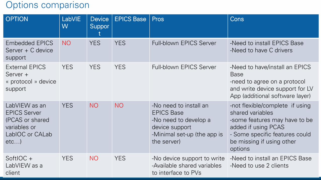
Options comparison
OPTION LabVIEW
DeviceSuppor
t
EPICS Base Pros Cons
Embedded EPICS Server + C devicesupport
NO YES YES Full-blown EPICS Server -Need to install EPICS Base-Need to have C drivers
External EPICS Server + « protocol » devicesupport
YES YES YES Full-blown EPICS Server -Need to have/install an EPICS Base-need to agree on a protocoland write device support for LV App (additional software layer)
LabVIEW as an EPICS Server(PCAS or sharedvariables or LabIOC or CALabetc…)
YES NO NO -No need to install an EPICS Base-No need to develop a device support-Minimal set-up (the app isthe server)
-not flexible/complete if usingshared variables-some features may have to beadded if using PCAS- Some specific features couldbe missing if using otheroptions
SoftIOC + LabVIEW as a client
YES NO YES -No device support to write-Available shared variablesto interface to PVs
-Need to install an EPICS Base-Need to use 2 clients

33ni.com
Conclusion
Several options to interface NI products with EPICS…
• Using LabVIEW as an IOC Server/client: Built-in : shared variables Add-ons by NI : PCAS VI library 3rd party add-ons : Shared memory, LabIOC, CALab, etc…
• Without using LabVIEW: cRIO : NI-RIO C API with NI Linux RT and Embedded Epics Base PXI : custom device support with instruments C drivers
…. On several operating systems (Windows, Linux desktop, VxWorks, Pharlap, NI Linux RT)

ni.com
TANGO interfacing with
NI technology
35ni.com
TANGO concepts
From NI HW/ NI LabVIEW to TANGO
36ni.com
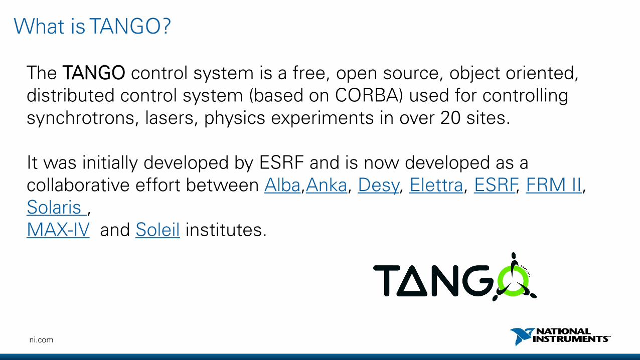
What is TANGO?
The TANGO control system is a free, open source, object oriented, distributed control system (based on CORBA) used for controlling synchrotrons, lasers, physics experiments in over 20 sites.
It was initially developed by ESRF and is now developed as a collaborative effort between Alba,Anka, Desy, Elettra, ESRF, FRM II, Solaris , MAX-IV and Soleil institutes.

ni.com
-It’s based on a client/server model (in C++, Java or Python).-It uses CORBA/Zeromq for network communication and the concept of Device Classes with object oriented programming.-Clients import these Devices via a database.
Architecture

38ni.com
TANGO devices
TANGO software bus
Device
class
Motor
Commands: On(), Off(), …
Attributes: Speed, Position
State: On, Off, Alarm, Fault
Polling, round robin buffer, threading,
event triggering, archiving …
Interface
Hardware control
code
Code generator
To be written by developers
POGO:• C++/Java/Python
glue code• Basic HTML doc
Supplier driver

39ni.com
TANGO
Application Logic
Hardware
Clients/Servers
Control System
CC
S
S
C
S
S
C
S Server Application.
Client application.
(applications network)
Interface
TANGO
Application Logic
-Send commands-Set/Get attributes-Subscribe to attributes events (periodic, change, archive, etc..)-No direct communication with devices
40ni.com
TANGO-NI interface

41ni.com
LabVIEW client (binding)
- Developed by Synchrotron SOLEIL
Interface
TANGO
Application Logic

42ni.com
TANGO
Application Logic
Hardware
TANGO-NI HW bridge (Device Server)
3 options:
• TANGO Server and NI HW are on the same machine & drivers are availableo One can develop his Device Server for NI HW by creating a class
for this HW and calling its NI driver
• TANGO Server and NI HW are NOT on the same machine or no drivers available or preferred programming IDEo One can do the same and calls will be done remotely through a
chosen communication protocol (TCP/IP, etc..)
• TANGO-LV add-on (Developed by SOLEIL : http://www.tango-controls.org/downloads/bindings/)

43ni.com
Generic architecture for LV-TANGO
Generic Device Server
(C++, Java, Python) LabVIEW API
Hardware
LV Driver
Shared Memory,TCP/IP, other..
InterProcessCommunication
TANGO Server
TANGO Client
Windows, Linux RTPXI, cRIO, Desktop
Corba
The App is the device

44ni.com
Remote Device Server : DAQ application example
One has to adapt his LV application architecture (state machine, events,…) to:• communicate with the client (via the Device Server) by using a communication protocol
instead of LV front panel controls• make some attributes available at any time if needed

45ni.com
State machine: Get client requests
TCP/IP chain LV Queues

46ni.com
State machine: Handle client requestsSet attributes/Run actions
Receive command/attribute
Write attribute Execute

47ni.com
State machine: Handle client requestsGet attributes values
Receive command/attribute
Write attribute Execute

48ni.com
Automatic conversion: no data flow change
Automatic conversion : VI Scripting
49ni.com
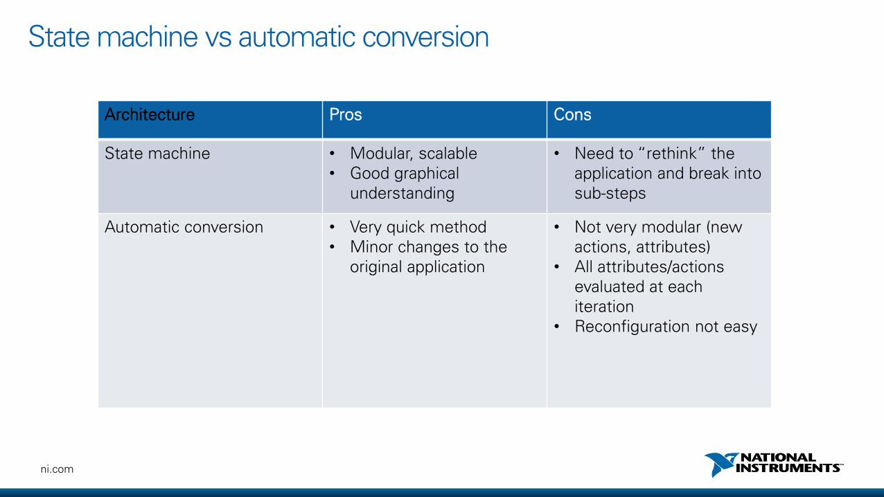
State machine vs automatic conversion
Architecture Pros Cons
State machine • Modular, scalable• Good graphical
understanding
• Need to “rethink” the application and break into sub-steps
Automatic conversion • Very quick method• Minor changes to the
original application
• Not very modular (new actions, attributes)
• All attributes/actions evaluated at each iteration
• Reconfiguration not easy
50ni.com
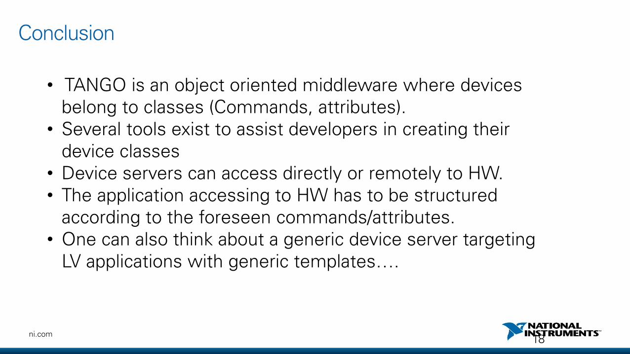
• TANGO is an object oriented middleware where devices belong to classes (Commands, attributes).
• Several tools exist to assist developers in creating their device classes
• Device servers can access directly or remotely to HW.• The application accessing to HW has to be structured
according to the foreseen commands/attributes.• One can also think about a generic device server targeting
LV applications with generic templates….
Conclusion
18

ni.com
Use LV to communicate with 3rd party PLCsand extend the I/Os

52ni.com
Agenda
• LV DSC• Shared variables• EPICS• OPC• Modbus• Ethercat
53ni.com
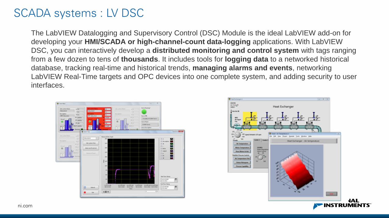
SCADA systems : LV DSC
The LabVIEW Datalogging and Supervisory Control (DSC) Module is the ideal LabVIEW add-on for
developing your HMI/SCADA or high-channel-count data-logging applications. With LabVIEW
DSC, you can interactively develop a distributed monitoring and control system with tags ranging
from a few dozen to tens of thousands. It includes tools for logging data to a networked historical
database, tracking real-time and historical trends, managing alarms and events, networking
LabVIEW Real-Time targets and OPC devices into one complete system, and adding security to user
interfaces.
54ni.com
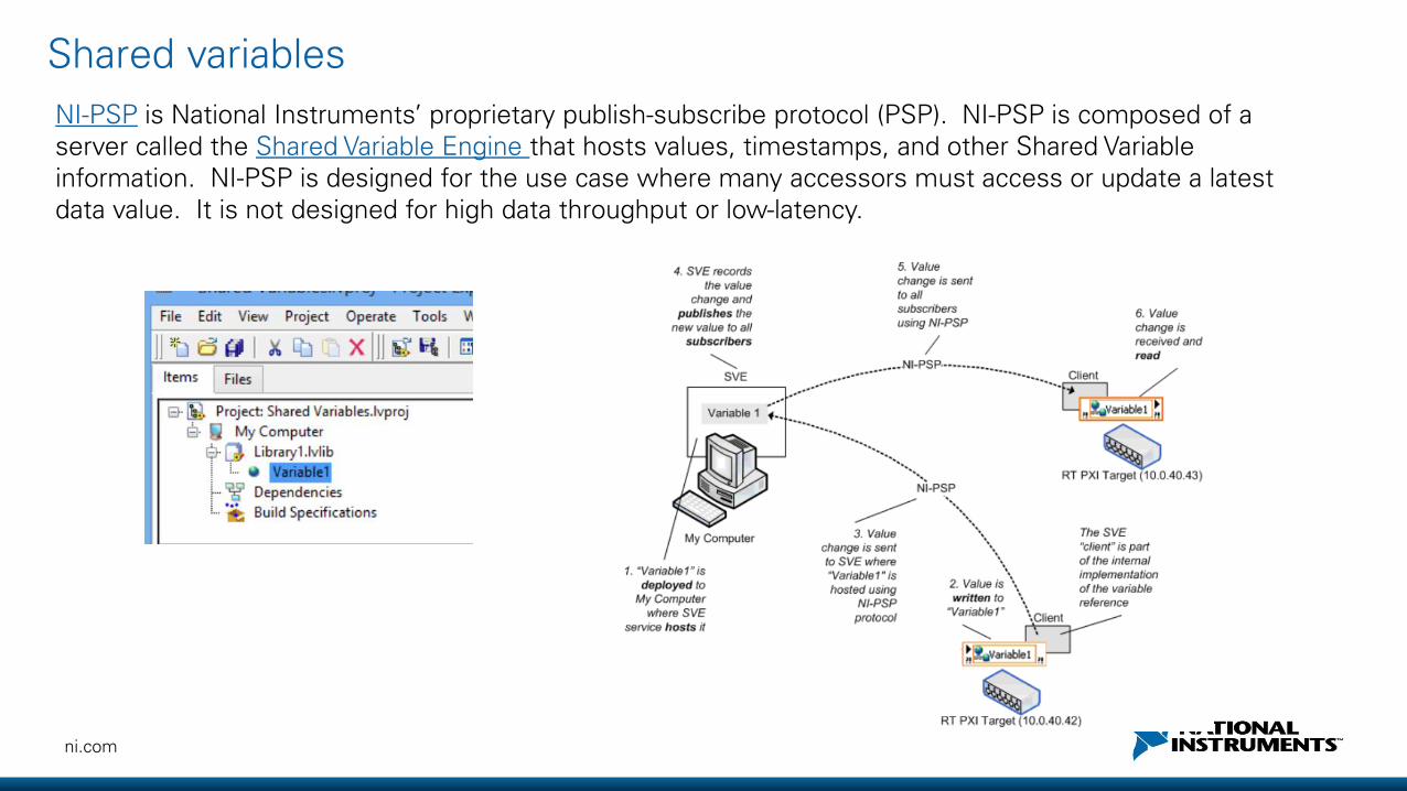
NI-PSP is National Instruments’ proprietary publish-subscribe protocol (PSP). NI-PSP is composed of a server called the Shared Variable Engine that hosts values, timestamps, and other Shared Variable information. NI-PSP is designed for the use case where many accessors must access or update a latest data value. It is not designed for high data throughput or low-latency.
Shared variables

55ni.com
Shared variables
56ni.com
EPICS (DSC & RT)

57ni.com
OPC, which is a Microsoft COM-based standard, allows client and server applications to
communicate with each other. OPC is designed to be an abstraction layer between industrial
networks and proprietary PLC drivers, and multi-vendor interoperability.
OPC is highly scalable and suited for high-channel-count systems.
• a tag gives a unique identifier to an I/O point (programmatically or user defined)
• Client software also specifies the rate at which the server supplies new data to the client.
The client software does not need to perform time-consuming data polling (event-driven
reactive object that waits for new data to arrive).
• The OPC server also provides alarm and event handling to client (operator parameters
change, access violations, conditions etc…)
OPC
58ni.com
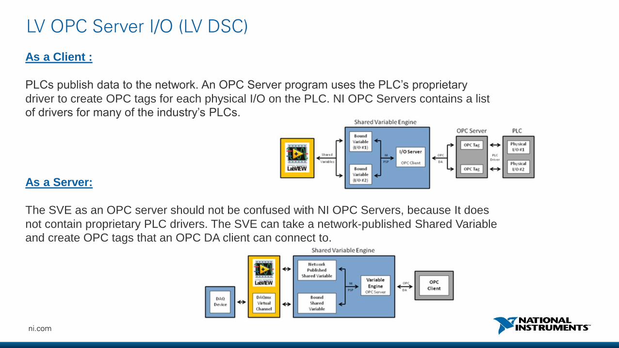
As a Client :
PLCs publish data to the network. An OPC Server program uses the PLC’s proprietary
driver to create OPC tags for each physical I/O on the PLC. NI OPC Servers contains a list
of drivers for many of the industry’s PLCs.
As a Server:
The SVE as an OPC server should not be confused with NI OPC Servers, because It does
not contain proprietary PLC drivers. The SVE can take a network-published Shared Variable
and create OPC tags that an OPC DA client can connect to.
LV OPC Server I/O (LV DSC)

59ni.com
LabVIEW allows developers to integrate with OPC systems. You can connect both OPC clients
and servers to LabVIEW applications to share data. The primary component that allows
LabVIEW to perform this action is the Shared Variable Engine (SVE).
LV OPC Server I/O

60ni.com
LabVIEW OPC UA Toolkit (or DSC or LV RT)
OPC Unified Architecture (UA) is a new communication technology standard. OPC UA includes all the
functionality found in OPC Classic.
OPC UA is based on a cross-platform, business-optimized Service-Oriented Architecture (SOA), which
expands on the security and functionality found in OPC.
• Expanded security (authentication and encryption)
• Easier IT integration (through firewalls, VPNs, etc..)
• Platform independance (Windows, OSX, Android, Linux etc.)
• Extensible (add new features with backward compatibility)
OPC UA
61ni.com
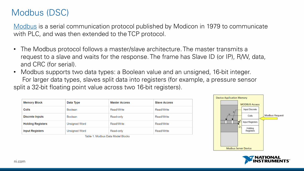
Modbus is a serial communication protocol published by Modicon in 1979 to communicate with PLC, and was then extended to the TCP protocol.
• The Modbus protocol follows a master/slave architecture. The master transmits a request to a slave and waits for the response. The frame has Slave ID (or IP), R/W, data, and CRC (for serial).
• Modbus supports two data types: a Boolean value and an unsigned, 16-bit integer.For larger data types, slaves split data into registers (for example, a pressure sensor
split a 32-bit floating point value across two 16-bit registers).
Modbus (DSC)
62ni.com
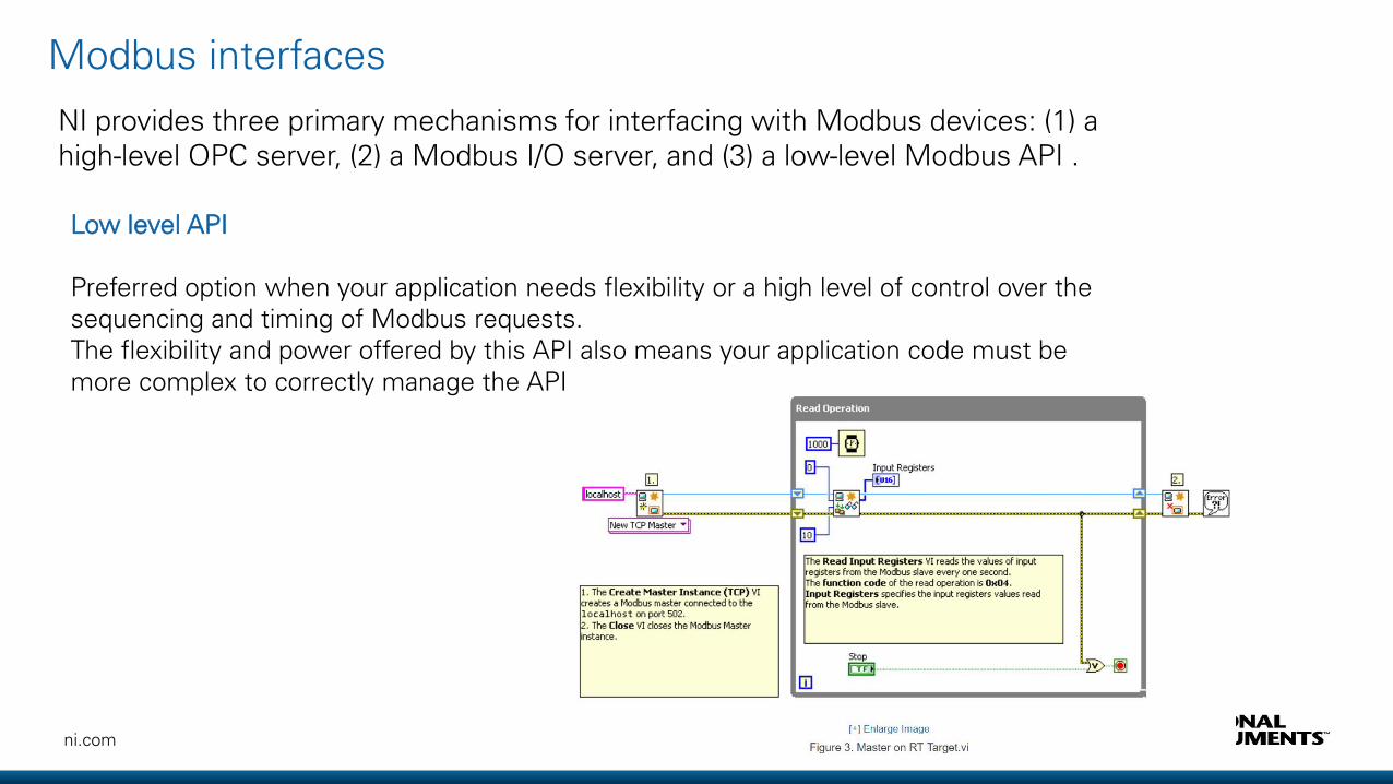
NI provides three primary mechanisms for interfacing with Modbus devices: (1) a high-level OPC server, (2) a Modbus I/O server, and (3) a low-level Modbus API .
Low level API
Preferred option when your application needs flexibility or a high level of control over the sequencing and timing of Modbus requests. The flexibility and power offered by this API also means your application code must be more complex to correctly manage the API
Modbus interfaces
63ni.com
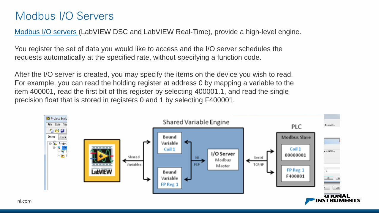
Modbus I/O servers (LabVIEW DSC and LabVIEW Real-Time), provide a high-level engine.
You register the set of data you would like to access and the I/O server schedules the
requests automatically at the specified rate, without specifying a function code.
After the I/O server is created, you may specify the items on the device you wish to read.
For example, you can read the holding register at address 0 by mapping a variable to the
item 400001, read the first bit of this register by selecting 400001.1, and read the single
precision float that is stored in registers 0 and 1 by selecting F400001.
Modbus I/O Servers
64ni.com
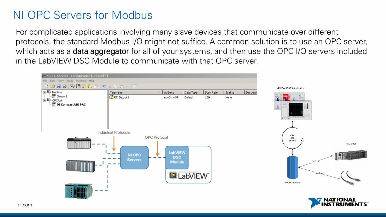
For complicated applications involving many slave devices that communicate over different protocols, the standard Modbus I/O might not suffice. A common solution is to use an OPC server, which acts as a data aggregator for all of your systems, and then use the OPC I/O servers included in the LabVIEW DSC Module to communicate with that OPC server.
NI OPC Servers for Modbus
65ni.com
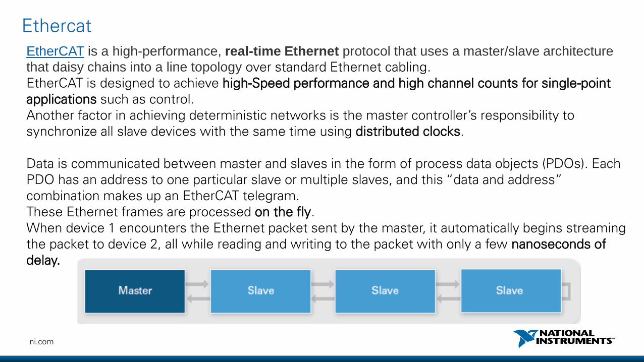
EtherCAT is a high-performance, real-time Ethernet protocol that uses a master/slave architecture
that daisy chains into a line topology over standard Ethernet cabling.EtherCAT is designed to achieve high-Speed performance and high channel counts for single-point applications such as control.Another factor in achieving deterministic networks is the master controller’s responsibility to synchronize all slave devices with the same time using distributed clocks.
Data is communicated between master and slaves in the form of process data objects (PDOs). Each PDO has an address to one particular slave or multiple slaves, and this “data and address” combination makes up an EtherCAT telegram. These Ethernet frames are processed on the fly.When device 1 encounters the Ethernet packet sent by the master, it automatically begins streaming the packet to device 2, all while reading and writing to the packet with only a few nanoseconds of delay.
Ethercat
66ni.com
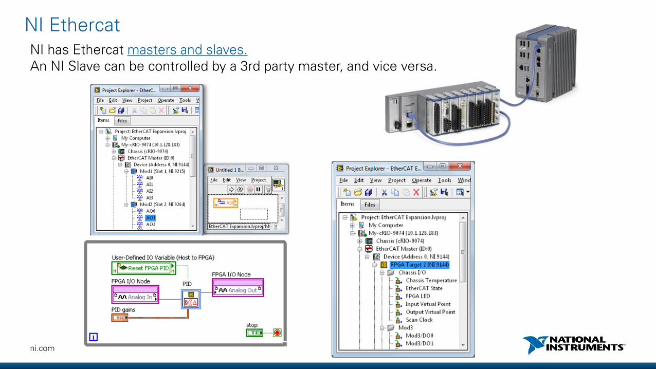
NI has Ethercat masters and slaves.An NI Slave can be controlled by a 3rd party master, and vice versa.
NI Ethercat

67ni.com
Benches examples
Ethercat performance
Synchronization <1µs
Throughput 12,5MB/s
Distance 100m beforerepeater
ni.com
New products and trends for Big Physics

69ni.com
Agenda
• Software designed-instruments• Deterministic ethernet & Synchronization• Distributed system management (SystemLink)• Linux support• PXI Co-processing (PXImc)
70ni.com
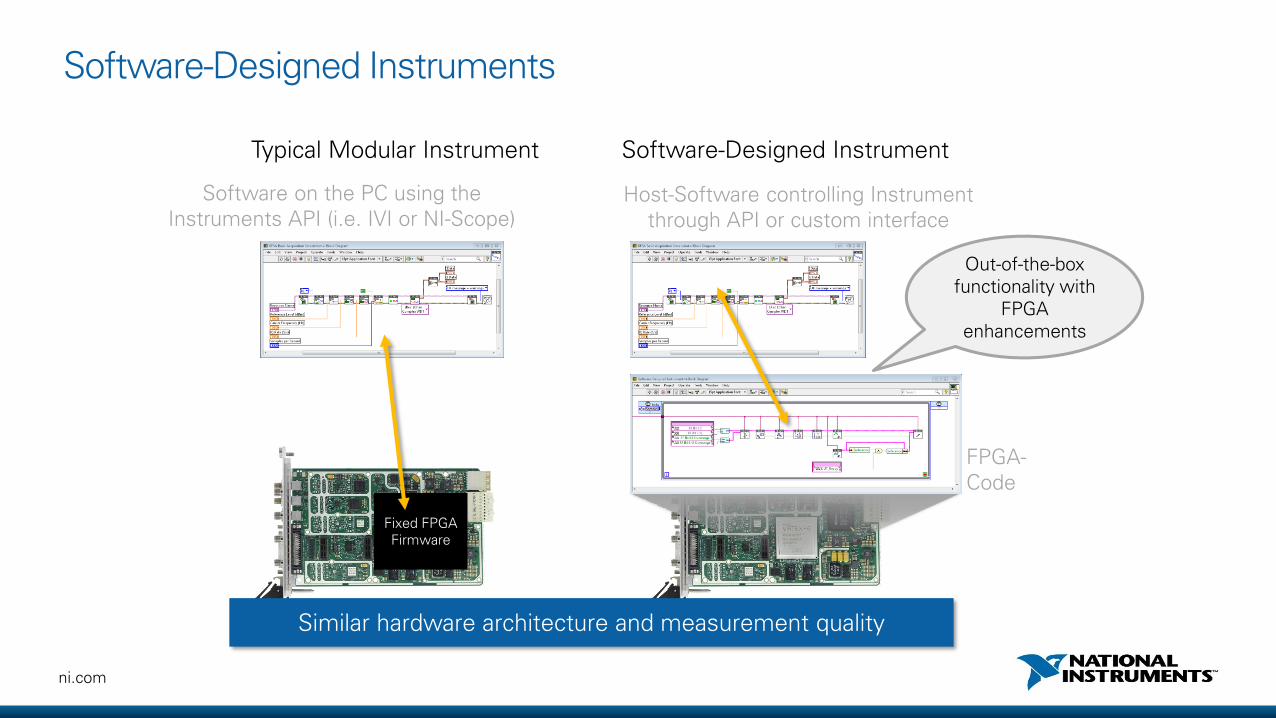
Software-Designed Instruments
Typical Modular Instrument Software-Designed Instrument
Software on the PC using the Instruments API (i.e. IVI or NI-Scope)
Fixed FPGA Firmware
FPGA-Code
Host-Software controlling Instrumentthrough API or custom interface
Similar hardware architecture and measurement quality
Out-of-the-box functionality with
FPGA enhancements

71ni.com
«open » instruments

72ni.com
PXIe-517xR Variants
Specification NI 5170R NI 5171R
Channel Count 4 8 8
Full Bandwidth 100MHz 250MHz
Selectable Filters - 100MHz
Open FPGA K7 325T K7 410T
Memory 750MByte 1.5GByte 1.5GByte
Resolution and Sample Rate
14-bit, 250MS/s
Input Ranges 200mVpp, 400mVpp, 1Vpp, 2Vpp, 5Vpp
Input configuration 50Ω, selectable AC or DC coupling per channel
Analog performance(preliminary data)
~ -78dBc (30MHz signal, anti-alias filter enabled)
>10 ENOB (full bandwidth, 0.4Vpp – 5Vpp ranges)
11 ENOB (anti-alias filter enabled, 0.4Vpp – 5Vpp ranges)
Part-Number Price (USD)Price (EUR)
783690-01$6,999€6.350
783691-01$9,999€9.070
783692-01$11,999€10.900

73ni.com
6674
7820
5170
5170
5170
5170
5170
5170
5170
5170
5170
5170
5170
5170
8384
Mu
ltiple
xer 1
Mu
ltiple
xer 4
. Multiplexer gate (trigger) to 5170R PFIx (0 to 3)
. PXI_Trig x line (1 per 4 multiplexers) from DIO to 5170R (serial encoding for channel number). Analog energy channel from multiplexer
. Digital lines from multiplexer for parallel channelnumber encoding (22*4 lines + 22 gates)
. 10Mz reference clock sharing (+ wire back)
. Start trigger sharing (+ wire back)
6674
8381 (MXIe
link)
5170
5170
5170
5170
5170
5170
5170
5170
5170
5170
5170
5170
5170
5170
5170
5170
5170
5170
5170
5170
5170
5170
224 channels 8381 MXIeLink
Copper MXIe
Copper MXIeto PCIe8381in the PC(3.2GB/s per dir)
2 freeslots
5170
5170
5170
5170
128 DSSD 4 Ge + 4 BGO 22 MUX, 2 TACs 4 Ge + 1-4 BGO 32 Si Tunnel
5170
5170
Reduced configurationIN2P3 architecture

74ni.com
Use cases
• Workaround to bandwidth or CPU performance limitation
• Create advanced triggers (frequency content, channels combinationetc…) and avoid unuseful data
• Implement custom on-the-fly processing (averaging, filtering, timestamping etc..)
• Lower testing times (control loops with P2P,
DUT control with digitial lines….)
• Continues processing without dead-time missing events

75ni.com
Application Example: Beam Position Monitoring
• Beam Position Monitor (BPM) measure the position of a particle beams in closed loop accelerators or storage machines while a BPPM in addition also measures the phase-relationship of particles to a RF-wave
• Acquire the signals of 250~500 MHz on 4 channels (±X, ±Y)
• Down-convert the RF-signals
• Extract position and phase-information from signal
• Provide position-data to control system
• Benefits of the new NI PXIe-5171R
• High Channel density (8 channels per PXI-slot)
• Signal processing in FPGA for time & frequency data in parallel
76ni.com
User Application on Host
Application-Specific FPGA VI
Instrument Design Libraries & Example Projects
Host
FPGA PCI Express
PCI Express
Embedded Controller (CPU)
Software-Designed Instrument(Oscilloscope)
Example Project VIs
Sample Project with user modifications
User Add-ons
Closed driver
User code
Open driver code
Instrument Design Library VIs

ni.com
Deterministicethernet

78ni.com
Typical machine control application sub-systems
HIGH PERFORMANCE I/O
MACHINE VISIONPROCESS AND MACHINE
HEALTH MONITORINGMULTI-AXIS MOTION
CONTROLLER
SAFETY SYSTEMSMACHINE-MACHINE
INTEGRATIONLOCAL HMI
PLANT INTEGRATION, PLM, SCADA
1µs 1µs 1µs 1µs
Closed-Loop Control at 5kHz
79ni.com
Technical Needs of Communications
Feature Need Needed For
GuaranteedBandwidth
Enable validation & analysis of system ability at design time
Reliable Operations
High BandwidthEnable high channel data and high speed streaming
Streaming of Data
Bounded Latency (and low)
Prioritize isochronous data over best effort on the same interconnect to maintain specified latency
Control Applications
Clock Synchronization
Allowing producers and consumers of isochronous data to be phase coordinatedAllow Application synchronization
Synchronized IO and Distributed Control
DistanceEnable separation of IO from controller or measurements of physically large systems
Application Dependent
Topology Provide physical options for wiring Application Dependent
EcosystemEnable the inclusion of third party devices such as drives
Application Dependent

80ni.com
“Standard” Ethernet• Best-in-class approach for openness
and interoperability
• Cannot bound latency (needed for control applications)
• Cannot guarantee bandwidth (needed for reliability)
The ChallengeH
ard
war
eS
oft
war
e
Network Infrastructure (Switches, cabling, etc)
Session, Presentation, and Application (Layers 5-7)
TCP/UDP (Layer 4)
IP (Layer 3)
MAC (Layer 2)
Physical (Layer 1)
Har
dw
are
So
ftw
are
Network Infrastructure (Switches, cabling, etc)
Session, Presentation, and Application (Layers 5-7)
TCP/UDP (Layer 4)
IP (Layer 3)
Special Hardware (Layer 2)
Physical (Layer 1)
Data Mux
“Hard Real-Time” Ethernet• Best-in-class approach for latency and control
• Cannot “share the wire” (no third party devices)
• Cannot scale with Ethernet (e.g. limited to 100 Mb/s)
• Proprietary HW/SW increases costs
Cu
stom
Sta
nd
ard
81ni.com
Har
dw
are
So
ftw
are
Network Infrastructure (Switches, cabling, etc)
Session, Presentation, and Application (Layers 5-7)
TCP/UDP (Layer 4)
IP (Layer 3)
MAC (Layer 2)
Physical (Layer 1)
Control Data
Queue Controller
TSN Ethernet
• Key industrial, embedded, and automotive vendors collaborating to drive requirements
• Best-in-class approach for control AND interoperability
• Bounded latency and guaranteed bandwidth
• Scales with Ethernet
TSN-Based “Hard Real-Time” Ethernet DevicesC
ust
om
Sta
nd
ard
82ni.com
Standards Efforts
Standards effort through IEEE 802 to improve latency and performance while maintaining interoperability and openness
Time Sensitive Networking (TSN) will provide:
• Time synchronization
• Bandwidth reservation for reliability
• Guaranteed bounded latency
• Low latency (preemption)
• Bandwidth (Gb+)
• Routable to support complex networks and wireless

83ni.com
Time Synchronization System ConfigurationTraffic Scheduling
Time Sensitive Networking: Key Elements

84ni.com
IEEE 802.1AS, IEEE 1588 Time Synchronization
Summary
End-nodes and switches share time
Features
• Synchronization of multiple systems using packet based communication
• Synchronization is possible over very long distances without impact from signal propagation delay
85ni.com
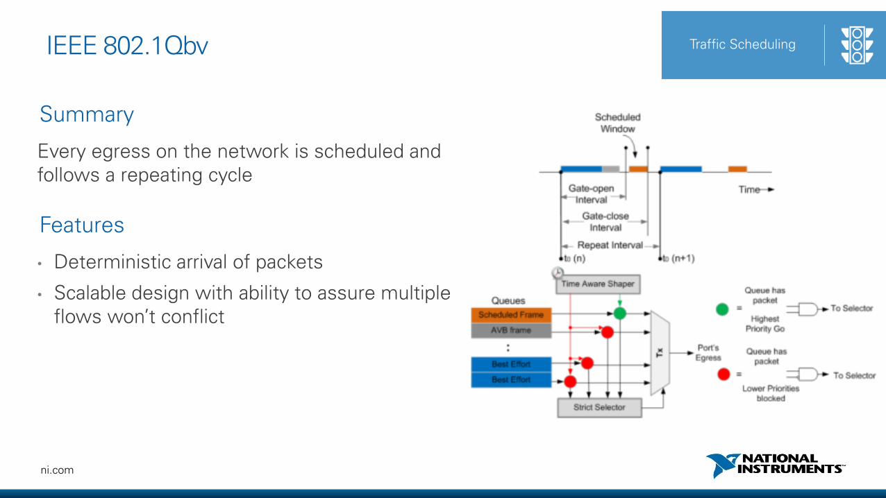
IEEE 802.1Qbv Traffic Scheduling
Summary
Every egress on the network is scheduled and follows a repeating cycle
Features
• Deterministic arrival of packets
• Scalable design with ability to assure multiple flows won’t conflict

86ni.com
IEEE 802.1Qcc System Configuration
Summary
Consistent mechanism for network configuration to meet the needs of end application
Features
• Standard mechanism for configuration of all network elements
• Configure “streams” between devices from any supplier

87ni.com
1. Time-based and isochronous programming in LabVIEW
2. Global time and synchronization for all processing elements and I/O
3. Bounded, low latency data transfer over Ethernet
National Instruments Investment
PXICompactDAQCompactRIO
LabVIEW System Design Software

ni.com
Manage deployedsystems

Challenge: Managing Deployed Systems
DAQ & ControlPlants / Facilities
DAQ & ControlDistributed Assets System Status
AlarmsNotifications
Software Deployment
Mobile Access
Remote Configuration
SYSTEMS MANAGEMENT
DATA AGGREGATION
Validation & Verification Test Production Test
System Replication
Data Transfer Security
Customers with distributed systems often encounter challenges in the management of devices, software, and data

SystemLink
Manage distributed systems with web application software that enables mass software deployment, device management, and data communications.
PRODUCT FEATURES
Track and manage a group of connected systems
Application access via web browser or mobile
Install on-premise or with a cloud service provider
EARLY ACCESS RELEASE DEVICE MANAGEMENT
Register hardware targets and classify systems through a shared interface.
New module available in early 2018
SOFTWARE CONFIGURATION
Deploy software to multiple remote targets, with upgrade, downgrade, & uninstall.
DATA COMMUNICATIONS
Automate data transfer among connected nodes, using LabVIEW or Web APIs.
SYSTEM HEALTH MANAGEMENT
Track and manage health of hardware with alarms and notifications.

Device Management
Track systems through a central
web interface
Search systems across all groups
Multi-select to perform remote
functions in parallel (e.g. install, restart).
View and manage detailed system and device information
Classify systems into groups
92ni.com
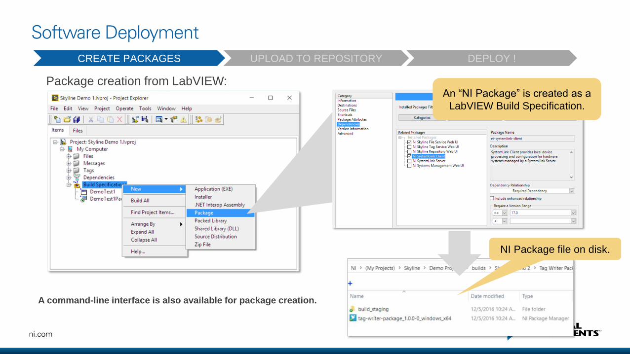
Software Deployment
Package creation from LabVIEW:
A command-line interface is also available for package creation.
NI Package file on disk.
CREATE PACKAGES UPLOAD TO REPOSITORY DEPLOY !
An “NI Package” is created as a
LabVIEW Build Specification.

93ni.com
Software Deployment
CREATE PACKAGES UPLOAD TO REPOSITORY DEPLOY !
Easily add new
packages to a Feed.
Create
deployment
Feeds to
organize
packages.
94ni.com
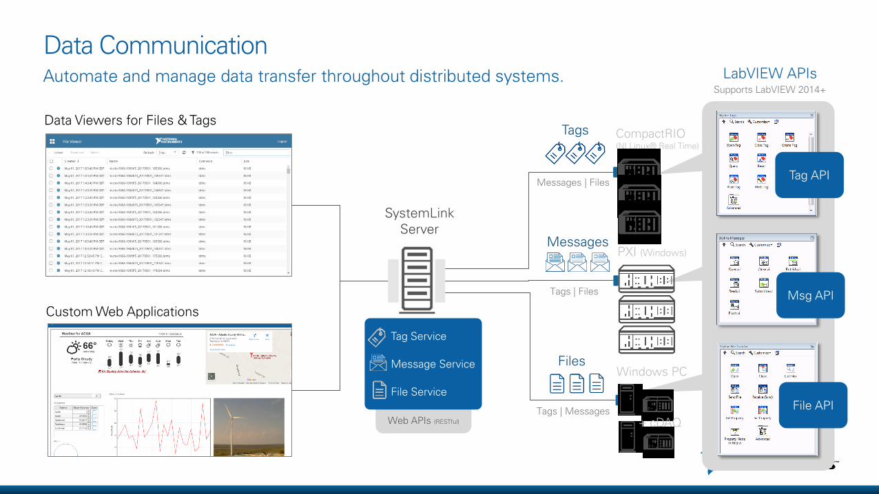
Web APIs (RESTful)
Data Communication
Tags
Messages
Custom Web Applications
Data Viewers for Files & Tags
Automate and manage data transfer throughout distributed systems.
SystemLink Server
Files
LabVIEW APIsSupports LabVIEW 2014+
CompactRIO (NI Linux® Real Time)
PXI (Windows)
Windows PC
+ cDAQ
Messages | Files
Tags | Files
Tags | Messages
Tag API
Msg API
File API
Tag Service
Message Service
File Service

Roadmap: Early 2018 Features
Dashboard Builder
• Browser-based application editor
• Drag-and-drop visualization widgets
• No coding required
• Connect UI controls to tags
• Mobile layouts
WebVI Hosting
System Health Monitoring
Test Sequence Monitor
• Create web UIs in LabVIEW NXG 2.0
• Host WebVIs on SystemLink Server
• VI executes in the browser (no plug-ins)
• Incorporates block diagram architecture
• Leverage data from tag service
• Central display of test status
• Interface with test executive
• TestStand plug-in
• Live updates as tests execute
• View/download test reports
• Monitor health metrics
• Configure alarm services
• Manage triggers and notifications
• Extensible with LabVIEW and Web APIs

SystemLink Architecture
Open and Extensible
APIs for LabVIEW and Web Services
Leverages several open-source standards
Optimized for Distributed Nodes Secure
Data communications are encrypted via TLS
Secure user access: LDAP & AD integration
Cloud-Ready
Install on premise or in the cloud
Cloud-centric developments on the horizon
Systems functions execute in parallel
Targets, server, & users can be on multiple networks
SystemLink: Supported Software & Hardware
SystemLink ClientsSystemLink Server
Windows Server
• Windows Server 2008 R2, SP1
• Windows Server 2012 R2
• Windows Server 2016
Windows PC
• Windows 7+
NI PXI
Windows PC
NI CompactRIO
Command-Line Support
NI & Non-NI Software
• Applications, libraries, drivers, docs,
installers, etc. can be packaged using
command-line interface and deployed
with SystemLink
WINDOWS TARGETS: Win 7+, 64-bit
NI LINUX RT TARGETS
WINDOWS OS Options: 64-bit
Deployment Software Hardware
* A LabVIEW plug-in is available to create
deployment packages with EXEs, PPLs and
Source Distributions.
LabVIEW* (32 & 64-bit) 2014-2017
LabVIEW Real-Time 2017
LabVIEW NXG 2.0
TestStand 2017
Native Packaging Tools

LV NXG

ni.com
NI Linux RT, Linux Desktop

100ni.com
Supported Hardware

101ni.com
• Enjoy the flexibility of Linux, with the determinism and reliability of a real-time operating system.
• Desktop UI, Peripherals, System Administration, Real-Time schedulers
• Leverage the vast ecosystem of tools and IP• Networking, Configuration Management, Simulation, Monitoring, etc.
• Reuse C/C++ code in and alongside LabVIEW Real-Time built applications• FPGA Interface C API, System Configuration C API
LabVIEW Support and Freedom in Development.

102ni.com
• Enable through MAX and/or Web Interface
• Can be used as a console
• Can be used to transfer files
• Permissions based on login
• SFTP
• Credentials synchronized with NI-Auth(Web Interface)
Secure Shell (SSH)

103ni.com
Leveraging the Linux Community
• NI Package Repository: download.ni.com/ni-linux-rt/
• OS source: github.com/ni
• Kernel Driver Support
Databases
SQLite
MySQL
PostgreSQL
Security
IPTables
OpenSSL
OpenVPN
Code Reuse
C/C++
Shell Scripts
Python
Connectivity
NTP
SNMP
IPv6

104ni.com
Security on NI Linux Real-Time
• SSL enabled by default
• Can programmatically install software over SSL
• Can use public keys for SSH
• IPtables* available for setting up a firewall
• OpenVPN* available for setting up a VPN
*Not supported by Applications Engineering. Requires experience. No LabVIEW API
105ni.com
System Updates on NI Linux Real Time
• NI Linux Real-Time targets can directly
call “Set Image”
• Enables targets to reimage themselves
• Images can be pulled down from the network or stored on a USB drive
• Specify additional metadata when creating an RT image (title, version, description)
106ni.com
Manage FPGA Bit Files
• Update and erase the FPGA bit files on NI Linux Real-Time targets programmatically, from MAX, and the web

107ni.com
LabVIEW 2014 Real-Time with Embedded UISimplify system complexity by implementing a local HMI on the cRIO

108ni.com
Eclipse for CompactRIO
• Choice of C and/or LabVIEW for programming processor
• LabVIEW FPGA still required
• FPGA Interface C API provides access to the FPGA from C
• Installer provided that includes Eclipse and Compiler
• Available on ni.com/downloads
Processing Subsystem
ARMA9
ARMA9
FPGA Fabric
LabVIEW FPGA Host InterfaceFPGA Interface C API

109ni.com
Eclipse Remote System Explorer
Targets
Remote System Details
Terminal/Console
Properties

ni.com
PXI Multi-Processing

111ni.com
Different NI supported Processing Technologies
Technology Advantages
Multi-Core CPUs
•Floating Point Operations•Diversity of Tasks•Parallelism based on n-cores
FPGAs
•Direct Connection to I/O for In-Line Processing•High Parallelism•High Throughput (fixed-point operations)
GP-GPUs
•Potentially High Throughput and Parallelism (for specific tasks)
But we need high-bandwidth and low-latency data transfer for distributed PXI chassis
112ni.com
Comparing Buses for Data Transfer
• Comparison Vectors:
• Bandwidth: The amount of data that can be transmitted in a given time
• Latency: The time it takes from the first bit to travel from the transmitter to the receiver.
GigabitEthernet
10 Gigabit Ethernet
PCI Express ReflectiveMemory
Bandwidth Good(60-70MB/s)
Better(600-700MB/s)
Best(3 GB/s)
Good(170 MB/s)
Latency Good(mS range)
Good(mS range)
Best(uS range)
Best(uS range)

113ni.com
PXImc System Topologies
Master PXI System
Mast
er
Co
ntr
olle
r
MX
Ie
MX
Ie
I/O
I/O
Secondary PXI System
Su
bsys
tem
C
on
tro
ller
I/O
I/O
I/O
Secondary PXI System
Su
bsys
tem
C
on
tro
ller
I/O
I/O
I/O
Secondary PXI System
Subsy
stem
C
ontr
olle
r
I/O
I/O
I/O
Secondary PXI System
Subsy
stem
C
ontr
olle
r
I/O
I/O
I/O
Secondary PXI System
Subsy
stem
C
ontr
olle
r
I/O
I/O
I/O
PXIe-8383mc
PXIe-8384
Master PXI System
Maste
r C
ontr
olle
r
I/O
I/O
I/O
x86 Compute Node x86 Compute Node x86 Compute Node x86 Compute Node
PCIe-8381
PXIe-8383mc

114ni.com
Co-Processing Module
• Intel® Core i7-4700EQ processor• 4 Physical and 8 Logical Cores• 2 x USB 2.0, 1 x Gigabit Ethernet LAN
ports• 4 GB (1 x 4 GB DIMM) dual-channel
1600 MHz DDR3 RAM• Up to 4GB/s theoretical (2.7 GB/s actual)
bandwidth for data transfer (single direction)
• 5 micro-second total (SW+HW) latency between co-processing module and main CPU
Industry’s First PXI Express Co-Processing Module

115ni.com
GPU processing (UPM University)
• Leverage FlexRIO, P2P, GPU and NI-RIO Open Source to implement continuous real time DAQ&Processing systems with minimum CPU intervention.
• Develop standardized methodologies to integrate these technologies in scientific research environments using NDS-EPICS
BEFORE AFTER
1 5
2 43 2
3
1

116ni.com
Stay Connected During and After NIDays
ni.com/community
facebook.com/NationalInstruments
twitter.com/niglobal
youtube.com/nationalinstruments