bil 201 mantıksal tasarım - hacettepeaykut/classes/fall2012/bbm231/... · • octal and...
TRANSCRIPT

BIL 201 Mantıksal Tasarım
(Logical Design)
Güz 2011 Bilgisayar Mühendisligi Bölümü
Hacettepe Üniversitesi
General Information • Web page:
To be announced later..
• Instructors:
Ahmet Burak Can,
Aykut Erdem
{abc,aykut}@cs.hacettepe.edu.tr
Office Rooms: 113/205
• Textbook:
Mano and Ciletti, Digital Design
Pearson, 4th Edition
• Other references:
Yarımagan, Sayısal Devrelerde
Mantıksal Tasarım, Bıçaklar Kitabevi
• Schedule:
Wednesday 9:15 – 12:00
• Message group:
piazza.com
2

Acknowledgements
• Course slides adapted from
- Textbook slides
- Slides of Nese Yalabik for CENG 232 – Digital Design
course (METU)
3

Course objectives
• To learn how to design, analyze, and evaluate digital (i.e. boolean) circuits
• To understand the workings of the computer - Hardware components
- How to design these basic components
- How to design digital circuits other than computers
4
Outline
• Historial overview
• Digital systems (sayısal sistemler)
• Binary numbers (ikili sayılar)
• Octal and Hexadecimal numbers (sekizli ve onaltılı sayılar)
• Complements (tümler)
• Addition and subtraction
• Binary codes (ikili kodlar)
• Binary storage and registers (ikili saklama ve yazmaçlar)
• Binary logic (ikili mantık)
• Logic gates (mantık kapıları)
5
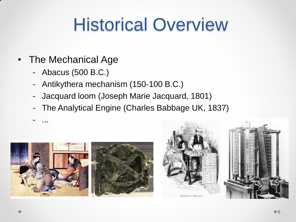
Historical Overview
• The Mechanical Age
- Abacus (500 B.C.)
- Antikythera mechanism (150-100 B.C.)
- Jacquard loom (Joseph Marie Jacquard, 1801)
- The Analytical Engine (Charles Babbage UK, 1837)
- ...
6

Historical Overview
• The Electrical Age
- Z3 (Konrad Zuse, Germany, 1941) (Turing-complete)
- ABC (Atanasoff and Berry, USA, 1942) (digital)
- Colossus Mark 1 (UK,1944)
- ENIAC (Mauchly and Eckert, USA, 1946)
- EDVAC (von Neuman, USA, 1951), …
7
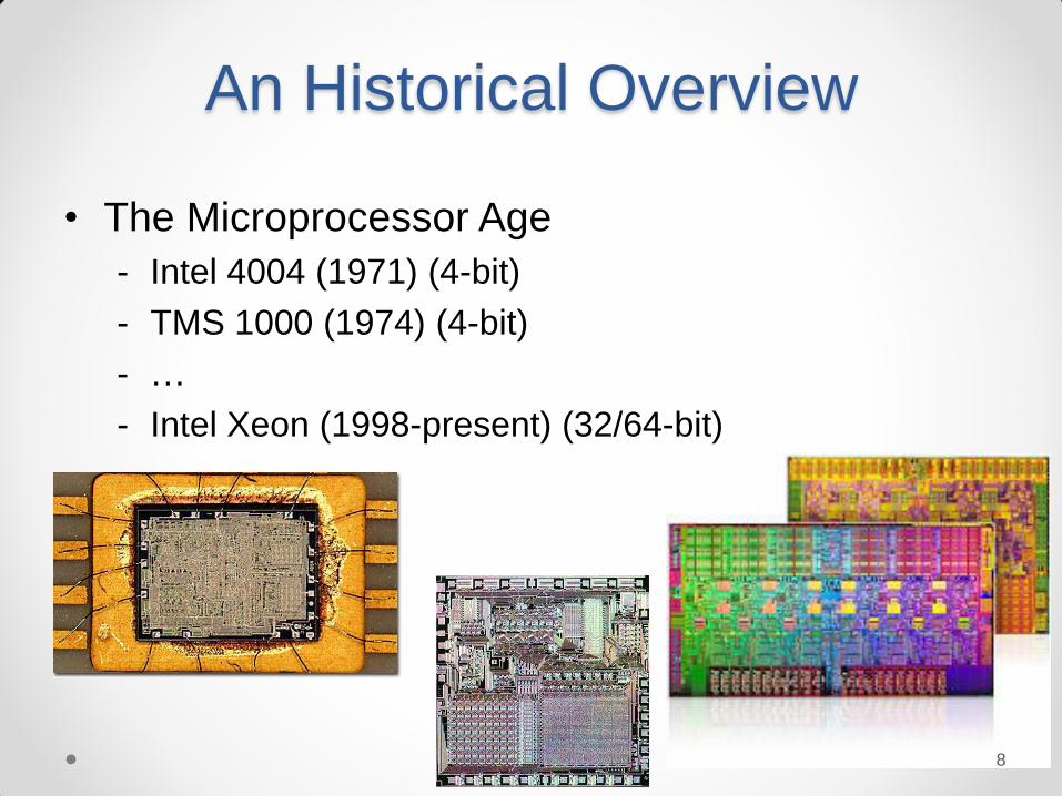
An Historical Overview
• The Microprocessor Age
- Intel 4004 (1971) (4-bit)
- TMS 1000 (1974) (4-bit)
- …
- Intel Xeon (1998-present) (32/64-bit)
8
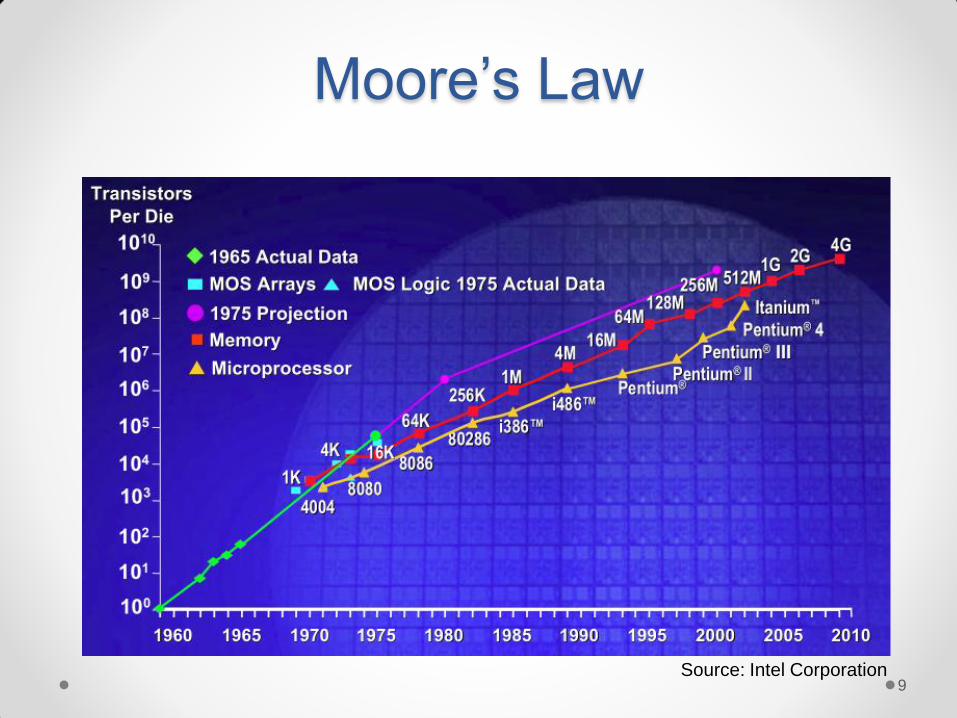
Moore’s Law
Source: Intel Corporation 9

Digital systems
• Digital computers, smart phones, digital cameras, etc.
• A digital system has the ability to represent and
manipulate discrete elements of information Finite set of information, e.g. 10 decimal digits, the 26 letters
of the English alphabet, the 64 squares of a chessboard
• Digital systems manipulate information as 1s and 0s
- binary codes
(the mapping of symbols to binary value)
- a binary digit is called a bit, has two values 0 and 1
r)(represented by electrical signals that can have one of
two voltage levels)
10

• Digital vs. analog waveforms
Analog: • values vary over a broad range
continuously
Digital: • only assumes discrete values
+5
V
–5
1 0 1
T ime
+5
V
–5
T ime
Digital systems
11

Digital systems
• Add two numbers in an analog circuitry
Design a circuit that will perform Z=X+Y
• Add two numbers in digital circuitry
3
4
7 volts volts
volts
Analog
Adder
Digital
(Binary)
Adder
0 0 1 1
0 1 0 0
0 1 1
1
0,1 can be around
0-5 volts
12
Digital systems
• Digital binary system
- Two discrete values:
• yes, on, 5 volts, current flowing, “1”
in practice varies between 4 and 5.5 for outputs and a wider
range for inputs
• no, off, 0 volts, no current flowing, “0”
between 0 and 1
• Advantages of binary systems
- Rigorous mathematical foundation based on logic
- It’s easy to implement
- Less error prone than analog
13

Decimal numbers
• We humans use decimal system of numbers
• A weighted position number system
7394 = 7x10³ + 3x10² + 9x101 + 4x100
• The decimal system is also called base (radix) 10 system
• Purely a human invention
“It is India that gave us the ingenious method of expressing all numbers by means of ten symbols, each symbol receiving a value of position as well as an absolute value; a profound and important idea which appears so simple to us now that we ignore its true merit.” – Laplace
14

Number systems
• In general, a number is represented in a base-r
system as:
N = an r n + an-1 r
n-1 + … + a1 r 1 + a0 r
0 + a-1 r -1 + … +
a-(m-1) r –m+1 + a-mr -m
each coefficient aj ranges between 0 to r-1
15

• r = 2 is called the binary system
• The coefficients (digits) are 0 and 1.
e.g., 26.75 = 11010.11
= 1x24 + 1x23 + 0x22 + 1x21 +0x20 + 1x2-1 + 1x2-2
• Least Significant Bit (LSB)
- The bit on the rightmost position
• Most Significant Bit (MSB)
- The bit on the leftmost position
Binary numbers
• Bit – a single binary digit
• Nibble – a group of four bits
• Byte – a group of eight bits
• Word – 8, 16, 32, or 64 bits
(depends on processor)
16
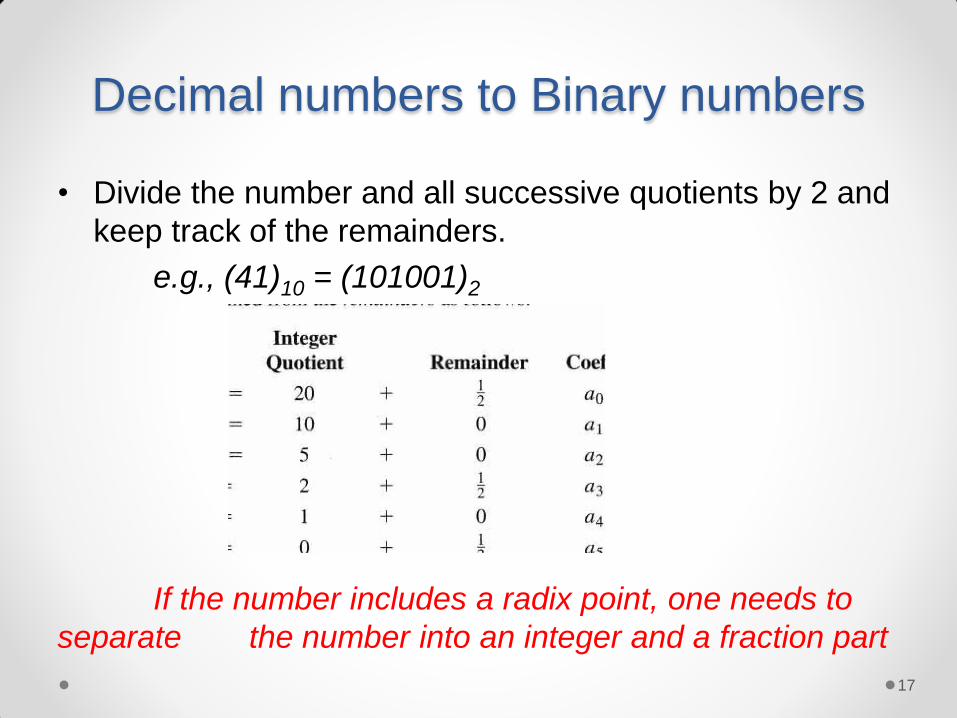
Decimal numbers to Binary numbers
• Divide the number and all successive quotients by 2 and
keep track of the remainders.
e.g., (41)10 = (101001)2
If the number includes a radix point, one needs to
separate the number into an integer and a fraction part
17

Decimal fractional numbers to binary
• Use multiplication (instead of division)
e.g., (0.6875)10 = (0.1011)2
Conversion may not be exact, i.e. a repeated fraction
18

Decimal fractional numbers to binary
Convert 13.2 to binary
Integer Fraction
13 / 2 = 6 R 1 LSB .2 x 2 = 0.4 MSB
6 / 2 = 3 R 0 .4 x 2 = 0.8
3 / 2 = 1 R 1 .8 x 2 = 1.6
1 / 2 = 0 R 1 MSB .6 x 2 = 1.2
.2 x 2 = 0.4 LSB repeating
Result is 1101.00110011…...
To check correctness, you can always convert back
the result to decimal
19

• Some simplifications over binary system
• r = 8 is called the octal system
- 8 digits: 0, 1, 2, …, 6, 7
e.g., (127.4)8 = 1x82 + 2x81 + 7x80 + 4x8-1 = (87.5)10
• r = 16 is called the hexadecimal system
- 16 digits: 0, 1, …, 9, A(10), B(11), C(12), D(13), E (14), F (15)
e.g., (B65F)16 = 11x163+6x162 + 5x161 + 15x160 = (46.687)10
The number represented in these number systems can
be easily converted to/from binary
Octal and Hexadecimal Systems
20

©2007 by Prentice Hall, Inc.
A Pearson Company
Figure Number: Table01 02
Mano/Ciletti
Digital Design, 4e
TB0102
©2007 by Prentice Hall, Inc.
A Pearson Company
Figure Number: Table01 02
Mano/Ciletti
Digital Design, 4e
TB0102
Binary numbers
21
Octal and Hexadecimal
Systems
• Conversion to/from decimal follows the same
strategy with a radix of 8 or 16 instead of 2
• To convert from binary:
- Starting at radix point, go left/right and group bits into
groups of 3 or 4 bits / group
- Convert each bit group into equivalent octal or hex
digit
• To convert to binary expand each octal / hex
digit into equivalent 3 or 4 bit binary value.
22
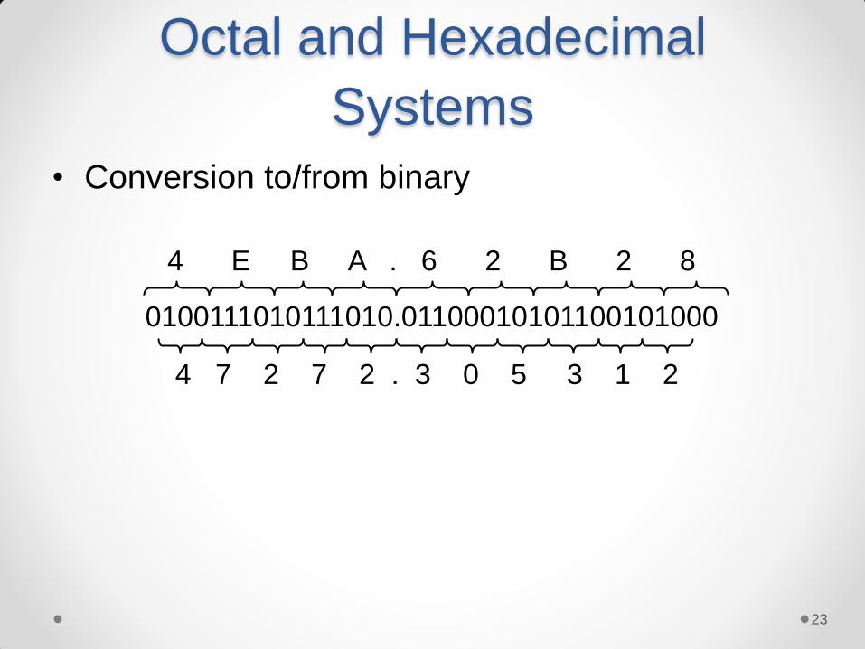
Octal and Hexadecimal
Systems
• Conversion to/from binary
0100111010111010.01100010101100101000
4 E B A . 6 2 B 2 8
4 7 2 7 2 . 3 0 5 3 1 2
23

Representing unsigned numbers
• All the n bits are assumed to represent only
positive numbers
• For integers, between 0 – (2n-1) (inclusive)
e.g. An 8 bit word can represent unsigned numbers
{00000000,00000001,……,11111111}
i.e. 0,1,2,…,(28-1) =255 in decimal
24

Representing signed numbers
• Positive number representation same in most
systems
- Standard positional binary notation
- MSB is the sign bit, 0 = plus, 1 = minus
- Nearly half are positive, half are negative
• Major differences are in how negative numbers
are represented
• Three major schemes:
- Sign-magnitude
- 1’s complement
- 2’s complement 25

• Assume a 4-bit machine word
• High order bit is the sign 0 = positive (or zero), 1 = negative
• Three low order bits is the magnitude: 0 (000) through 7 (111)
• Number range for n bits = ±2n-1 - 1
• Two representations for 0
• The major disadvantage is that we
need separate circuits to both add
and subtract
• Number magnitudes need to be
compared to get the right result
Sign-Magnitude representation
+0 +1
+2
+3
+4
+5
+6
+7
0001 0000
0010
0011
0100
0101
0110
0111 1000
1100
1001
1010
1011
1101
1110
1111
-7
-6
-5
-4
-3
-2
-1 -0
0 100 = +4
1 100 = - 4
26

Representing -N
• How to represent –N?
• A - B is equivalent to A + (-B)
• We really are working in a closed, modulo
number system, 0 to 2r-1 values
• Therefore for r bits, 2r 0
• If -N 0 - N then -N 2r - N
The 2’s complement representation for
-N
27

+0 +1
+2
+3
+4
+5
+6
+7
0001 0000
0010
0011
0100
0101
0110
0111 1000
1100
1001
1010
1011
1101
1110
1111
-1
-2
3
-4
-5
-6
-7 -8
2’s complement representation
• Only one representation for 0
• One more negative number
than positive number
• Generation of the 2’s
complement as 2r - N implies
r+1 bits available in system
28

2’s complement representation
• Twos complement of 7 24 = 10000
subtract 7 = _0111
1001 = repr. of -7
• Twos complement of -7 24 = 10000
subtract -7 = _1001
0111 = repr. of 7
• Twos complement = Bitwise complement +1
0111 1000 + 1 1001 (representation of -7)
1001 0110 + 1 0111 (representation of 7)
29

1’s complement representation
• N is positive number, then N* is its negative 1's complement
N* = (2n - 1) – N
e.g., 1's complement of 7
• Simply compute bitwise complement 0111 => 1000
24 = 10000
-1 = 00001 1111 -7 = 0111 1000
= -7 in 1's comp.
30

+0 +1
+2
+3
+4
+5
+6
+7
0001 0000
0010
0011
0100
0101
0110
0111 1000
1100
1001
1010
1011
1101
1110
1111
-0
-1
-2
-3
-4
-5
-6 -7
like 2's comp except shifted one position counter-clockwise
Ones complement
representation
• Subtraction implemented by
addition & 1's complement
• Still two representations of 0!
causes some problems
• Some complexities in addition
31
4
+ 3
7
0100 0011 0111
-4
+ (-3)
-7
1100 1011 1111
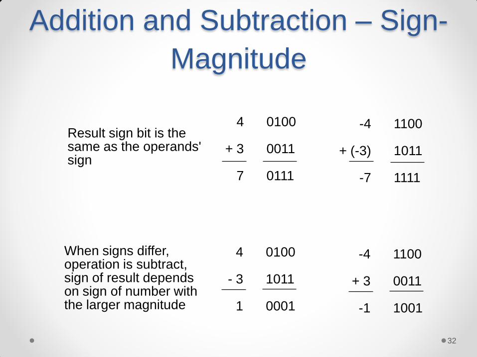
Result sign bit is the same as the operands' sign
4
- 3
1
0100 1011 0001
-4
+ 3
-1
1100 0011 1001
When signs differ, operation is subtract, sign of result depends on sign of number with the larger magnitude
Addition and Subtraction – Sign-
Magnitude
32

4
+ 3
7
0100 0011 0111
-4
+ (-3)
-7
1011
1100
10111
1
1000
4
- 3
1
0100
1100
10000
1
0001
-4
+ 3
-1
1011 0011 1110
End around carry
End around carry
Addition and Subtraction –
1’s Complement
33

Addition and Subtraction –
1’s Complement
• Why does end-around carry work?
Its equivalent to subtracting 2n and adding 1
M - N = M + N* = M + (2n - 1 - N) = (M - N) + 2n - 1 (M > N)
-M + (-N) = (2n - M - 1) + (2n - N - 1) = 2n + [2n - 1 - (M + N)] - 1
M + N < 2n-1
after end around carry: = 2n - 1 - (M + N)
The correct form for representing -(M + N) in 1's complement! 34
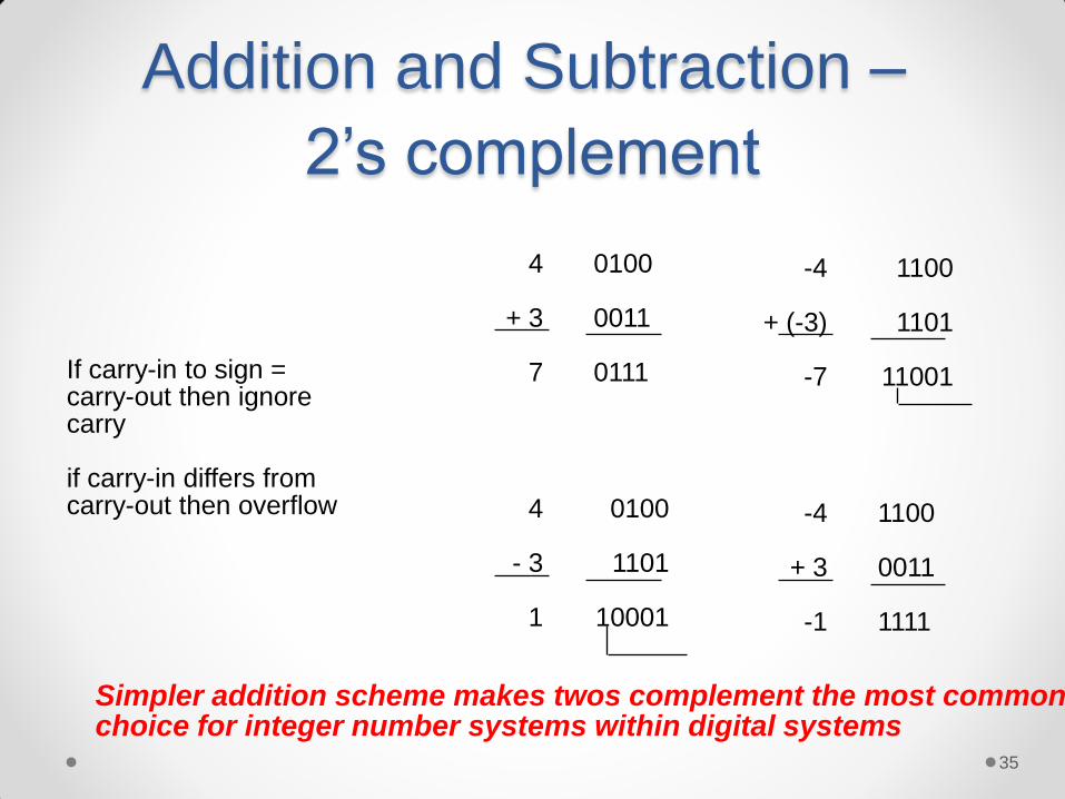
Addition and Subtraction –
2’s complement
4
+ 3
7
0100 0011 0111
-4
+ (-3)
-7
1100
1101
11001
4
- 3
1
0100
1101
10001
-4
+ 3
-1
1100 0011 1111
If carry-in to sign = carry-out then ignore carry if carry-in differs from carry-out then overflow
Simpler addition scheme makes twos complement the most common choice for integer number systems within digital systems
35

Addition and Subtraction –
2’s complement • Why can the carry-out be ignored?
-M + N when N > M:
M* + N = (2n - M) + N = 2n + (N - M)
Ignoring carry-out is just like subtracting 2n
-M + -N where N + M < or = 2n-1
-M + (-N) = M* + N* = (2n - M) + (2n - N) = 2n - (M + N) + 2n
After ignoring the carry, this is just the right two’s compliment representation for -(M + N)!
36
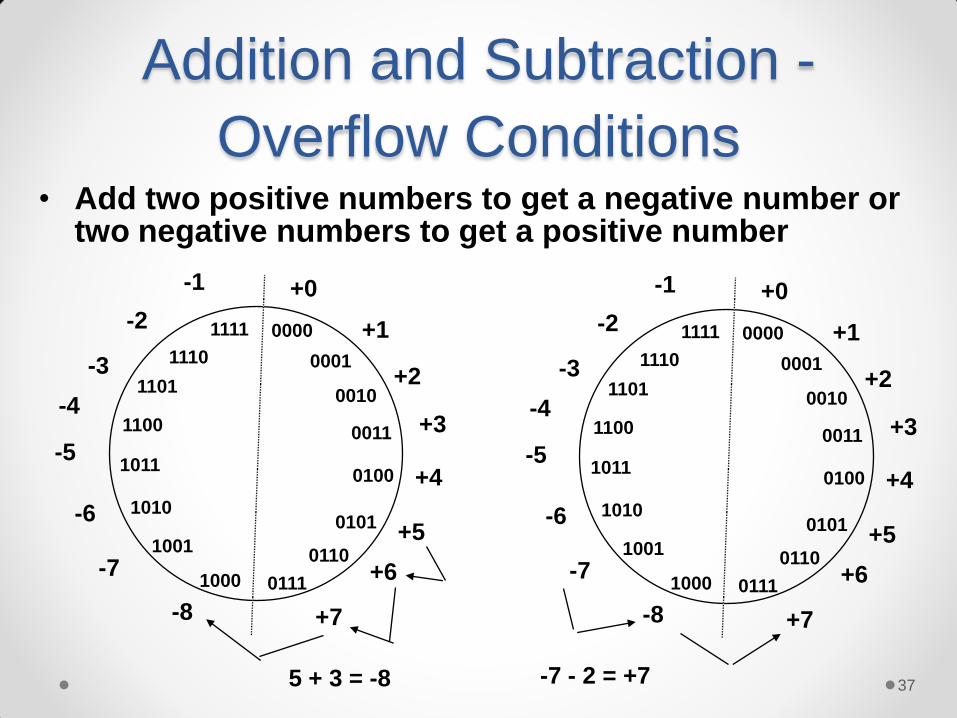
Addition and Subtraction -
Overflow Conditions
5 + 3 = -8
0000
0001
0010
0011
1000
0101
0110
0100
1001
1010
1011
1100
1101
0111
1110
1111
+0
+1
+2
+3
+4
+5
+6
+7 -8
-7
-6
-5
-4
-3
-2
-1
-7 - 2 = +7
0000
0001
0010
0011
1000
0101
0110
0100
1001
1010
1011
1100
1101
0111
1110
1111
+0
+1
+2
+3
+4
+5
+6
+7 -8
-7
-6
-5
-4
-3
-2
-1
• Add two positive numbers to get a negative number or two negative numbers to get a positive number
37

Overflow Conditions
5
3
-8
0 1 0 1 0 0 1 1 1 0 0 0
-7
-2
7
1 0 0 1 1 1 0 0 1 0 1 1 1
5
2
7
0 1 0 1 0 0 1 0 0 1 1 1
-3
-5
-8
1 1 0 1 1 0 1 1 1 1 0 0 0
Overflow Overflow
No overflow No overflow
Overflow when carry in to sign does not equal carry out
38

Weighted and unweighted
codes
• Most numeric number representations are in a
class known as weighted codes where
• Binary integers and fractions are special case
where weights are powers of 2
• Unweighted codes are codes that cannot be
assigned a weight value for each bit
val = bi ×wii=0
r-1
å
39
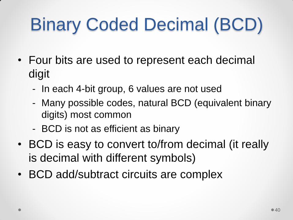
Binary Coded Decimal (BCD)
• Four bits are used to represent each decimal
digit
- In each 4-bit group, 6 values are not used
- Many possible codes, natural BCD (equivalent binary
digits) most common
- BCD is not as efficient as binary
• BCD is easy to convert to/from decimal (it really
is decimal with different symbols)
• BCD add/subtract circuits are complex
40

Binary codes
©2007 by Prentice Hall, Inc.
A Pearson Company
Figure Number: Table01 05
Mano/Ciletti
Digital Design, 4e
TB0105
Unweighted code
Weighted codes
The 8421 or natural BCD code is the most common BCD code
in use 41

BCD Addition
Case 1: Case 2:
Case 3:
0001 1 0101 5 (0) 0110 (0) 6
0110 6 0101 5 (0) 1011 (1) 1
1000 8 1001 9 (1) 0001 (1) 7
WRONG!
Note that for cases 2 and 3,
adding a factor of 6 (0110)
gives us the correct result.
42

BCD Addition
• BCD addition is therefore performed as follows
- 1) Add the two BCD digits together using normal
binary addition
- 2) Check if correction is needed
• a) 4-bit sum is in range of 1010 to 1111
• b) carry out of MSB = 1
- 3) If correction is required, add 0110 to 4-bit sum to
get the correct result; BCD carry out = 1
43

Negative BCD Numbers
• Similar to binary negative number
representation except r = 10.
- BCD sign-magnitude
• MSD (sign digit options) o MSD = 0 (positive); not equal to 0 = negative
o MSD range of 0-4 positive; 5-9 negative
- BCD 10’s complement
• -N 10r - N; 9’s complement + 1
- BCD 9’s complement
• invert each BCD digit
(09, 1 8, 2 7,3 6, …7 2, 8 1, 9 0) 44

Negative BCD Numbers
• 84-2-1 and XS3 codes allow for easy digit
inversion.
• XS3 code is also easy to implement
- Addition is like binary
- Correction factor is -3 or +3
45

Gray codes
• Grey codes are minimum change codes - From one numeric
representation to the next, only one bit changes
- Primary use is in numeric input encoding apps. where we expect non-random input values changes (i.e. value n to either n-1 or n+1)
• Milling machine table position
• Rotary shaft position
©2007 by Prentice Hall, Inc.
A Pearson Company
Figure Number: Table01 06
Mano/Ciletti
Digital Design, 4e
TB0106
46
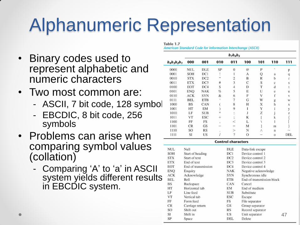
Alphanumeric Representation
• Binary codes used to represent alphabetic and numeric characters
• Two most common are: - ASCII, 7 bit code, 128 symbols
- EBCDIC, 8 bit code, 256 symbols
• Problems can arise when comparing symbol values (collation) - Comparing ‘A’ to ‘a’ in ASCII
system yields different results in in EBCDIC system.
©2007 by Prentice Hall, Inc.
A Pearson Company
Figure Number: Table01 07
Mano/Ciletti
Digital Design, 4e
TB0107
47
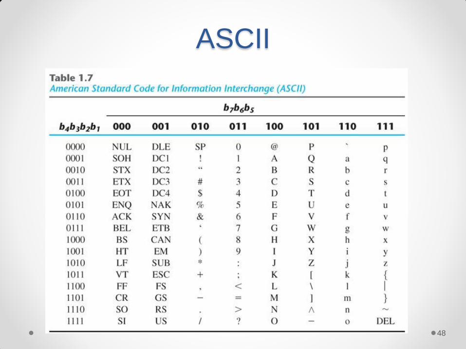
ASCII
©2007 by Prentice Hall, Inc.
A Pearson Company
Figure Number: Table01 07
Mano/Ciletti
Digital Design, 4e
TB0107
48

Parity Bit
• ASCII code may have an extra bit appended to
detect data transmission errors
- P = 0 if the number of 1s in the character is even, else
P = 1 (even parity)
- P = 0 if the number of 1s in the character is odd, else
P = 1 (odd parity)
• If any single bit changes, parity will be wrong at
receive end
Even parity Odd parity
ASCII A = 1000001 01000001 11000001
ASCII T = 1010100 11010100 01010100
49

Other information
representation
• ALL information must be encoded before we can
design circuits to process it
• You can assign any code to any information
- e.g., 00 - north, 01 - east, 11 - south, 10 - west
• If the information goes somewhere else, the user
has to have access to your definition
• Standards are best if available
- Already published and easily available
- Allows your system to work with many others
50
Binary Storage and Registers
• A binary cell is a device that possesses two
stable states
- Can store a single bit (0 or 1) of information
• A register is a group of binary cells
- A register with n cells can store n-bit of information
51
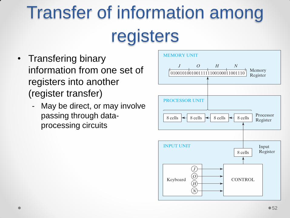
Transfer of information among
registers • Transfering binary
information from one set of
registers into another
(register transfer)
- May be direct, or may involve
passing through data-
processing circuits
52

Binary information processing
• Binary variables are
manipulated by means of
digital logic circuits
- e.g., an adder circuit
53
Binary logic
• Binary logic deals with binary variables and a set
of logical operations.
- Binary variables can take only two values, 0 and 1.
• 3 basic logical operations: AND, OR and NOT
For x and y binary variables, the three logical operations
are shown as:
- AND operation () xy
- OR operation (+) x+y
- NOT operation ’ x’
54

Binary logic
©2007 by Prentice Hall, Inc.
A Pearson Company
Figure Number: Table01 08
Mano/Ciletti
Digital Design, 4e
TB0108
55

Logic gates
• Logic gates are electronic circuit which implement basic logic operations. - Electrical signals (voltages, currents,
etc.) are treated as 0 or 1.
• Logic 0 may be defined as 0 volts and logic 1 may be defined as 5 volts.
• But usually the range of voltages are used - 0: 0V to 1V
- 1: 2V to 3V
Having a range of allowable voltage
values makes the binary logic less prone to
errors. 56

Logic gates
57

Logic gates
58