billikensat – ii nano-satellite that conforms to the cubesat standard team leader: darren pais...
TRANSCRIPT
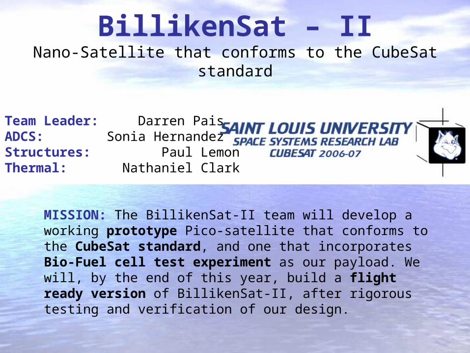
BillikenSat – IINano-Satellite that conforms to the CubeSat standard
Team Leader: Darren PaisADCS: Sonia HernandezStructures: Paul LemonThermal: Nathaniel Clark
MISSION: The BillikenSat-II team will develop a working prototype Pico-satellite that conforms to the CubeSat standard, and one that incorporates Bio-Fuel cell test experiment as our payload. We will, by the end of this year, build a flight ready version of BillikenSat-II, after rigorous testing and verification of our design.

Agenda for today
Introduction Payload Structures Thermal ADCS Conclusions
• Overview of mission experiment
• Detailed description and progress in key areas:
Payload Structures Thermal Attitude Determination Attitude Control Electrical and Computer Engineering, Interfaces
Emphasize the integrated, multi-disciplinary nature of BillikenSat – II.

Payload Concept
Introduction Payload Structures Thermal ADCS Conclusions
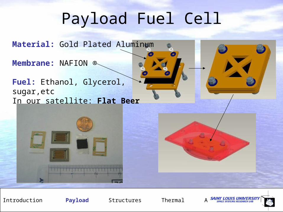
Payload Fuel Cell
Introduction Payload Structures Thermal ADCS Conclusions
Material: Gold Plated Aluminum
Membrane: NAFION ®
Fuel: Ethanol, Glycerol, sugar,etcIn our satellite: Flat Beer

Payload Structure
Introduction Payload Structures Thermal ADCS Conclusions
Material• Poly Ether Ether Ketones- PEEK• Conducts 1/1000th the amount of heat relative to Aluminum • Upper working temperature of 250 oC
Tank Design• Plate and tank bolted together around seal• PEEK pipe for pressurization on ground and testing• Tank able to withstand 1500 psi
Screw
Pipe
Ferrule
Ref: Gere, Mechanics of Materials, Thomson 2003

Structural Assembly
Introduction Payload Structures Thermal ADCS Conclusions
• Internal components bolted to mounts• Bolts and mounts universal • Spring washers and lock-nuts ensure connection
• Exterior panels screw or slide into rails• Panels provide extra strength to structure• PCB and carbon composite panels under consideration
Composite panel
Solar Cell

Structures- Putting things together
Introduction Payload Structures Thermal ADCS Conclusions
(1) Main Structural Bus (2) Exploded View (3) Assembled Satellite
Ref: Megson, Aircraft Structures for Engineers, Butterworth 1999

Structures- 3 view and dimensions
Introduction Payload Structures Thermal ADCS Conclusions
Electronic Boards
Battery Box
Payload

Support Panel
Introduction Payload Structures Thermal ADCS Conclusions
Preliminary design • Cross braces resist tension effectively• Slots for exterior panels to slide into
Evolved design • Thicker cross bars to better resist compression and bending• More access to interior for mounting, etc.• Easier to manufacture• 4 side panels screwed on, 2 slide into place• Mount deflection due to 9g loading is negligible (1.48x10⁻⁴mm)
Old Design
Evolved Design

Vibration Modeling
Introduction Payload Structures Thermal ADCS Conclusions
• High Level Qualification studied• Frequency range expected on launch 0-2000 Hz • Pro Mechanica Modal analysis conducted• Calculations performed to confirm computer results• Natural frequencies studied to ensure no match with rocket frequencies
Crossbeam Mode 1
Pro Mechanica = 3051 Hz
Theory Calculation = 3039 HzRef: Mechanical Vibrations, S. Rao (1998)
Modal response of constrained side panel in Mode 1.
Note: Modal deflection highly exaggerated in clip

Battery Box Design
Introduction Payload Structures Thermal ADCS Conclusions
Design• House batteries while providing access• Provide Structural backbone• Resist loads from many directions
Analysis• Natural frequencies found using Pro-Mechanica Mode 1 = 1459 Hz Mode 2 = 2702 Hz• Maximum deflection under 9g load due to batteries = 0.0028 mm

Mass Budget
Introduction Payload Structures Thermal ADCS Conclusions
• Total mass estimated to be 825 gram• 175 grams available for contingency
Structure44%
Electrical37%
Thermal2%
ADCS5%
Payload12%Sub System Mass (g)
Structure 362ADCS 40
Electrical 306Payload 102Thermal 15TOTAL 825

System Interface Diagram
Introduction Payload Structures Thermal ADCS Conclusions

Introduction Payload Structures Thermal ADCS Conclusions
Orbital Parameters
BillikenSat will follow Sun synchronous / near polar orbit
Orbital Parameters DNEPR 07
Type of Orbit Sun synchronous
Inclination 98 deg
Eccentricity 0.009
RAAN 256 deg
Argument of Perigee 0 deg
Mean Anomaly 0 deg
LTAN 22:30 UTCG
Altitude Perigee 660 km
Altitude Apogee 772 km
Period 90 min
Introduction Payload Structures Thermal ADCS Conclusions
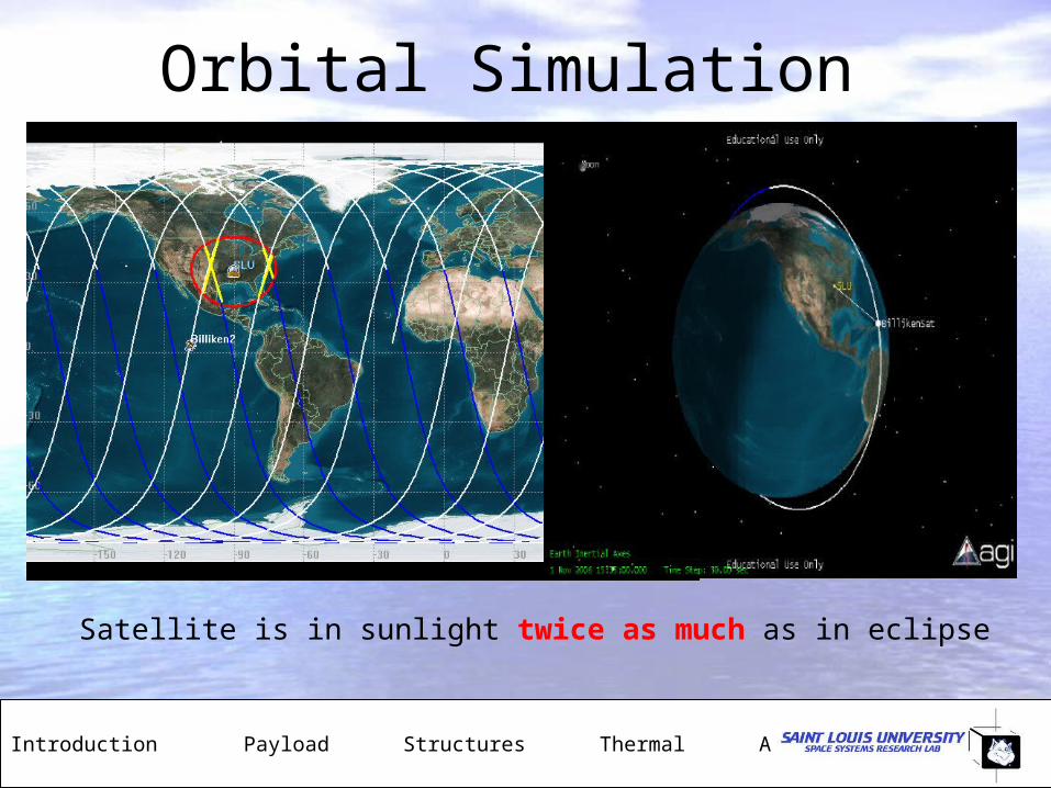
Orbital Simulation
Satellite is in sunlight twice as much as in eclipse
Introduction Payload Structures Thermal ADCS Conclusions
Communication Window
21 deg.
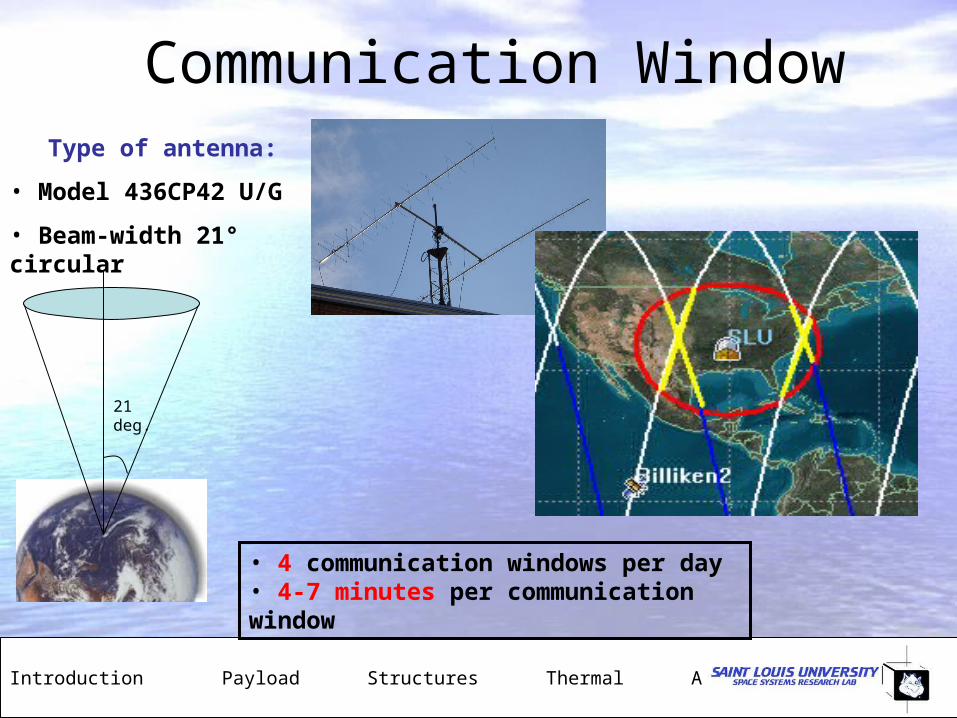
Type of antenna:
• Model 436CP42 U/G
• Beam-width 21° circular
• 4 communication windows per day • 4-7 minutes per communication window

Introduction Payload Structures Thermal ADCS Conclusions
Equilibrium Temperatures
Radiation absorbed:
Radiation emitted:
Temperature equilibrium:
ia AGQ
4bodyre TAQ
4bodyri TAAG
:
:
:
:
:
:
r
i
A
A
G
irradiation
absorptivity
incident area
emissivity
Stefan-Boltzmann const.
radiating area
CT o4.46max CT o7.111min ,
aQ
eQ

Introduction Payload Structures Thermal ADCS Conclusions
Actual Temperatures1. Find total energy transfer rate for
sunlight
2. Use energy transfer rate to find temperature at end of sunlight
3. Find total energy transfer rate for eclipse
4. Use energy transfer rate to find temperature at end of eclipse
• Repeat
Operating Range: -40.9oC to 44.2oC
Ref: Cengel, Intro to Thermodynamics and Heat Transfer, McGraw Hill 1997

Introduction Payload Structures Thermal ADCS Conclusions
Heat Transfer of Payload Box
4bodyre TAQ
Heat loss at 25oC of 2.57 W
Heater power is 1.13 W
Surface treatment: aluminized Mylar© ‘space blanket’ with emissivity of 0.03
Payload survival range 4oC to 40oC
Introduction Payload Structures Thermal ADCS Conclusions
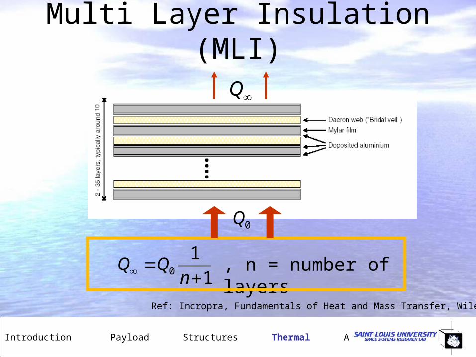
Multi Layer Insulation (MLI)
1
10
nQQ , n = number of layers
Q
0Q
Ref: Incropra, Fundamentals of Heat and Mass Transfer, Wiley 2001

Introduction Payload Structures Thermal ADCS Conclusions
MLI ComponentsMylar©: 0.025 mm
Dacron web: 0.18 mm
Dacron
Mylar
Single Layer Pair for MLI

Introduction Payload Structures Thermal ADCS Conclusions
Active Thermal Control
Thermofoil© Heater
43.94 mm (1.73 in) diameter 0.3 mm (0.012 in) thickness
Platinum RTD
1.24 x 1.7 x 2.41 mm
(0.049 in x 0.067 in x0.095 in)

Introduction Payload Structures Thermal ADCS Conclusions
Feedback Loop
platinum RTD
If V>V @ 15oC
If V<V @ 30oC
take no action
turn on heater
turn off heater
true
false
false
true
Heating for 7 min 16 sec, cooling for 18 min 18 sec

Introduction Payload Structures Thermal ADCS Conclusions
Electronics• Most components can operate within
temperature range– Battery pack: how much insulation?
• Calculate heat transfer through payload wiring
• Testing– Find actual performance of heater– Calibrate resistance temperature
detector (RTD)

Introduction Payload Structures Thermal ADCS Conclusions
1. If gyro is not spinning: wheel flops over
2. If gyro is spinning: Gyro rotates in a direction perpendicular to the applied force
•Based on principle of conservation of angular momentum.
•Once spinning, it tends to resist changes to its orientation due to the angular momentum of wheel.
Gyroscopes will determine at what rate the satellite is turning
Attitude Determination: Gyroscopes

Introduction Payload Structures Thermal ADCS Conclusions
Tradeoff study of gyroscopesSensor Fibersense
FOG 1Analog
ADXRS150Analog
ADXRS300SiliconSensingCRS 03
HoneywellCMG
Pro reason Fiber optics:very highresolution
Small size:mass &volume
Small size:mass &volume
Extremelyhigh
accuracy
Extremelyhigh
accuracy
Pro reason Power req.+/- 5V DC
Power req.+/- 5V DC
Power req.+/- 5V DC
Con reason Not enough information
supplied
Limitedavailability
Notavailablefor 1 year
Sizeconstraints
Sizeconstraints
Con reason Ships fromJapan
High price

Introduction Payload Structures Thermal ADCS Conclusions
ADXRS 150Properties:• Complete rate gyroscope on a single chip• Z-axis (yaw rate) response• Self-test on digital command• 5V single-supply operation• Very light (< 0.5g)• Range: +/- 150deg/s• Sensitivity: 12.5 mV/deg/s• Temperature range: -40 to 85 C• Total chip: 7mm x 7mm x 3mm
The rate gyroscope uses Coriolis effect to sense the speed of rotation.

Introduction Payload Structures Thermal ADCS Conclusions
ADXRS 150
Pin Configuration:
•RATEOUT: Voltage proportional to the angular rate about the axis normal to the top surface of the package
•SELF TEST FUNCTION: Works in same manner as if the gyro was subjected to angular rate.
It produces a positive going output voltage forclockwise rotation about the axis normal to the package top.

Attitude Control
Introduction Payload Structures Thermal ADCS Conclusions
Reasons for Attitude Control: Stability, Communications, Special Devices like cameras.
KEY OPTIONS
PASSIVE CONTROLACTIVE CONTROL
Magnetorquers
Control Moment Gyros
Reaction Wheels
Gravity Gradient
Permanent MagnetsHysteresis Dampers
Solar Sails
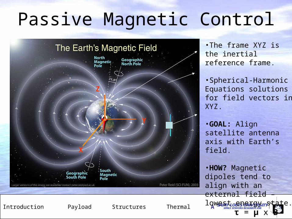
Passive Magnetic Control
Introduction Payload Structures Thermal ADCS Conclusions
X
Y
Z
•The frame XYZ is the inertial reference frame.
•Spherical-Harmonic Equations solutions for field vectors in XYZ.
•GOAL: Align satellite antenna axis with Earth’s field.
•HOW? Magnetic dipoles tend to align with an external field – lowest energy state.
τ = μ x B

Earth Magnetic Field @ 600km alt
Introduction Payload Structures Thermal ADCS Conclusions

Earth Magnetic Field @ 600km alt
Introduction Payload Structures Thermal ADCS Conclusions

Reference Frames- Attitude Dynamics
Introduction Payload Structures Thermal ADCS Conclusions
z
y
x
CCCSS
CSSSCCCSSSSC
SSCSCSCCSSCC
b
b
b
3
2
1
BIIdt
d
dt
d H
M
Roll, Pitch and Yaw Transformation
Euler’s Equation:
Coupled Differential equations:
Equations+Initial Conditions→Numerical discrete time simulation using Runge-Kutta 4, 5
yxzzyyz
zz
zxzzxxy
yy
zyyyzzx
xx
IIdt
dIM
IIdt
dIM
IIdt
dIM
3
2
1
321
21
21
C
SS
C
CS
dt
d
CSdt
d
C
S
C
C
dt
d
Ref: Wertz, Spacecraft AD and Control, Reidel 1984
Introduction Payload Structures Thermal ADCS Conclusions
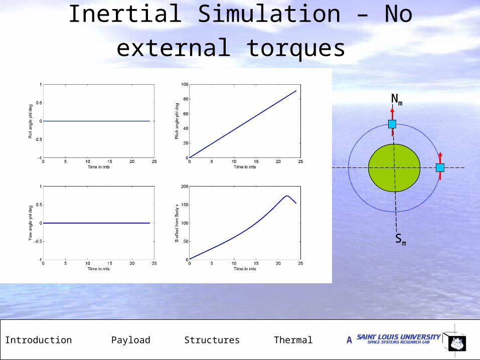
Inertial Simulation – No external torques
Nm
Sm
Nm
Sm
Introduction Payload Structures Thermal ADCS Conclusions
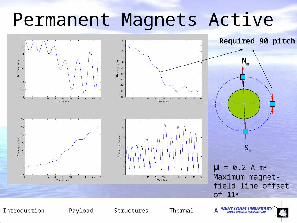
Permanent Magnets Active
Nm
Sm
Nm
Sm
Required 90 pitch
μ = 0.2 A m2
Maximum magnet-field line offset of 11o

Attitude Control Parameters
Introduction Payload Structures Thermal ADCS Conclusions
SIMULATION PARAMETERS:
MOMENTS OF INTERTIA:
Ixx = 1.5212 x 10⁻³ kg m2
Iyy = 1.448 x 10⁻³ kg m2
Izz = 1.507 x 10⁻³ kg m2
SIMULATION RESULTS:
Magnet Size (moment): 0.1 to 0.5 Am2
For ALNICO-5 size: 10-30 grams
Resolution Target: within 12 O
Typical Magnet
Typical Damper

Attitude Control Future Work
Introduction Payload Structures Thermal ADCS Conclusions
• Model Hysteresis damping and incorporate in satellite dynamics
• Convert dynamical differential equations into Quaternion format (‘cleaner’ math)
• Testing of magnetic and hysteresis materials for actual properties
• Study coupled hysteresis-permanent magnet dynamics
• Study gyroscopic (precession) effects on the attitude dynamics solutions/plots.
B
H

About CubeSat- Launch Vehicle
Introduction Payload Structures Thermal ADCS Conclusions
• Launch Site: Baikonur Cosmodrome, Kazakhstan
• Launch weight 211 Tons
• Uses SS-18 liquid-fuelled ICBM
• Three-stage in-line configuration.
• 3 P-PODS: each containing 3 CubeSats

About CubeSat- Testing Requirements
Introduction Payload Structures Thermal ADCS Conclusions
Specifications required by CalPoly need to be met in order to qualify for integration and launch:
•Structural dimension and weights requirements
•Thermal-vacuum chamber testing
•Vibration testing

Electrical & Computer Engineering
Introduction Payload Structures Thermal ADCS Conclusions
• Power (Brian Vitale): – Lithium Ion Batteries– Power distribution layout
completed• Communications (Mac Mills and
Thamer Bahassan): – Antenna design– FSK transceiver
• C&DH (Jorge Moya and Elena Nogales): – Onboard data collection and
computing. – Microprocessor PIC18
Typical EE board with components
• System Constraints– Max Bus Voltage (5-7 Volts Peak)– Operating frequency (approx. 433
MHz)– Electromagnetic interference
Future Work
Introduction Payload Structures Thermal ADCS Conclusions
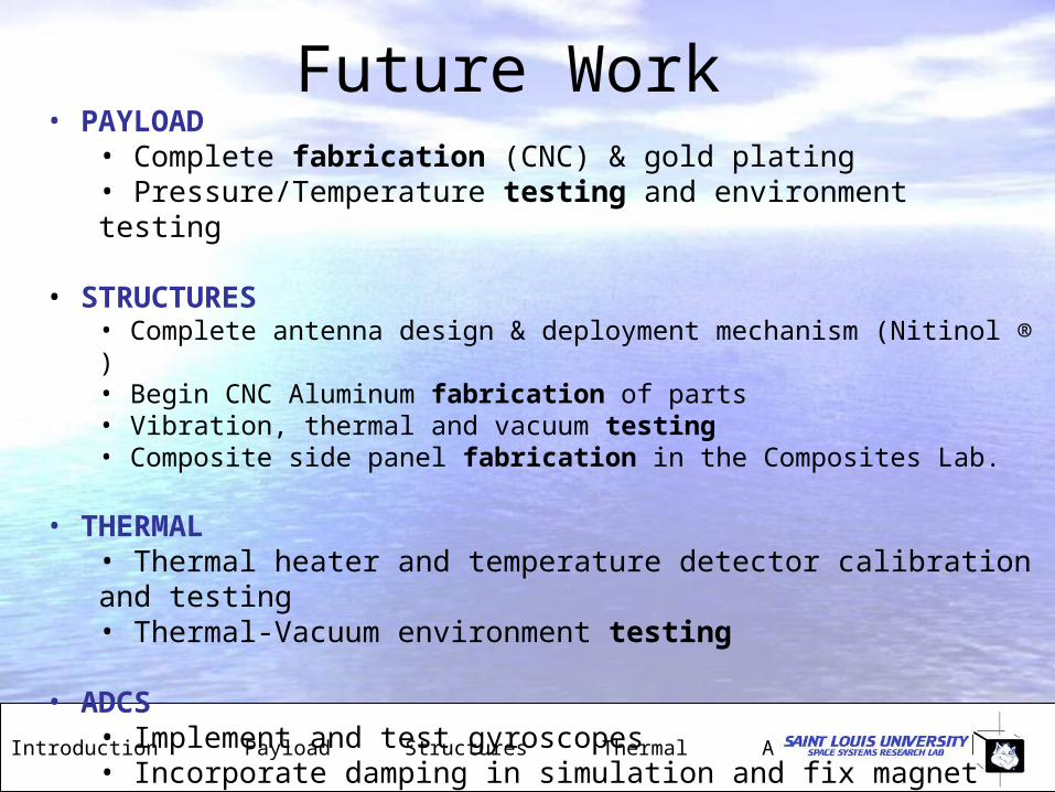
• PAYLOAD• Complete fabrication (CNC) & gold plating• Pressure/Temperature testing and environment testing
• STRUCTURES• Complete antenna design & deployment mechanism (Nitinol ® )• Begin CNC Aluminum fabrication of parts • Vibration, thermal and vacuum testing• Composite side panel fabrication in the Composites Lab.
• THERMAL• Thermal heater and temperature detector calibration and testing• Thermal-Vacuum environment testing
• ADCS • Implement and test gyroscopes• Incorporate damping in simulation and fix magnet sizing

Conclusions & Questions
Introduction Payload Structures Thermal ADCS Conclusions
• The interdisciplinary nature of this project is a new and exciting challenge for our team.
• Translation of analytical and design work to physical hardware and working integrated systems presents a unique challenge. Unexpected problems arise.
• Our focus on robust, well thought out design ideas, especially in the early design phase, has helped expedite our work.
• Design work is complete. Fabrication work has begun for key components and we are testing at the component and sub-system level at this time.
Special thanks to:•Dr. Benoy, Dr. Condoor, Dr. Ferman, Dr. Fitzgerald, Dr. George, Dr. Jayaram, Dr. Ravindra (AE & ME)•Mr. Frank Coffey (Parks AE & ME Labs)•Dr. Shelly Minteer and Rob Arechederra (Chemistry)•Dr. H. S. Mallik (Electrical Engineering)•Dr. Brody Johnson (Mathematics)•Ms. Jean Jackson (Parks Development)•Our freshman, sophomore & junior team members
Introduction Payload Structures Thermal ADCS Conclusions
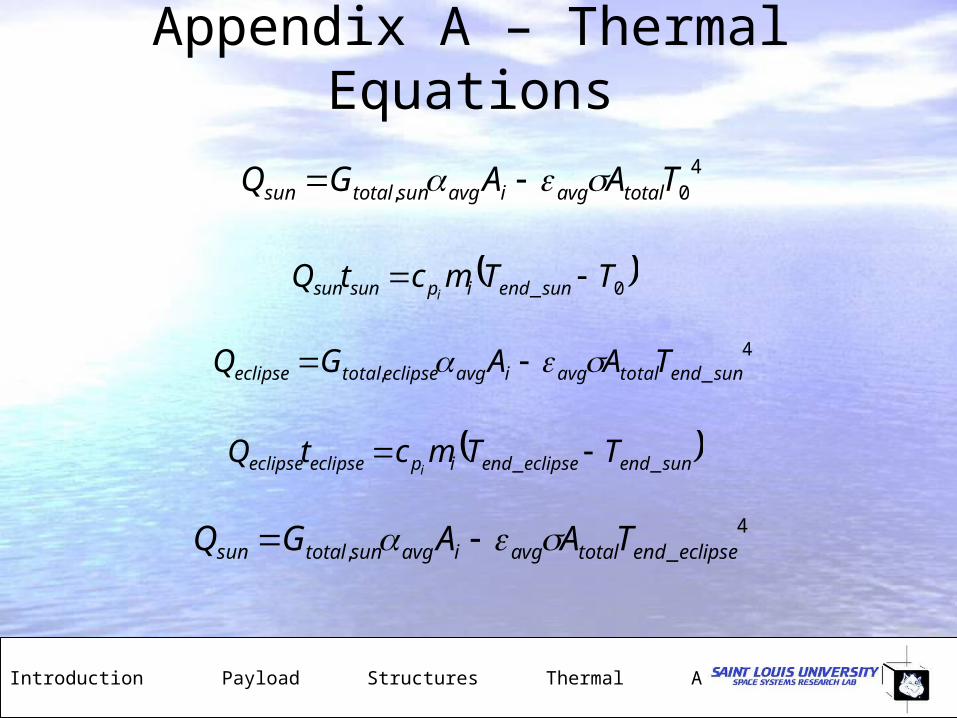
Appendix A – Thermal Equations
4_, sunendtotalavgiavgeclipsetotaleclipse TAAGQ
40, TAAGQ totalavgiavgsuntotalsun
0_ TTmctQ sunendipsunsun i
sunendeclipseendipeclipseeclipse TTmctQi __
4_, eclipseendtotalavgiavgsuntotalsun TAAGQ

Appendix B – More Drawings
Introduction Payload Structures Thermal ADCS Conclusions

Appendix C – Thermal Expasion
Introduction Payload Structures Thermal ADCS Conclusions
o o
o o
Thermal Expansion of Structure
40 40
Aluminum 6061-O
Coefficient of Thermal Expansion
linear 68 F 23.6 m/mC
linear 250 C 25.2 m/mC
PEEK (unreinforced)
Coefficient of Thermal Expansi
o oC T C
o o
o o
9 4
on
linear 20C Average = 44.1 m/mC
linear 100C Average = 39.2 m/mC
Vertical Displacement
Aluminum components
113
0.113 23.6 10 / 80 1000 2.13 10o o
h mm
mmh CTE T m m mC C mm
m
9 4
9 4
PEEK Components
0.113 44.1 10 / 80 1000 3.99 10
Horizontal Displacement
Aluminum components
100
0.1 23.6 10 / 80 1000 1.88
PEEK Components
80
o o
o o
mmh CTE T m m mC C mm
m
l mm
mml CTE T m m mC C mm
m
l mm
h CT
9 40.0.8 44.1 10 / 80 1000 2.82o o mmE T m m mC C mm
m
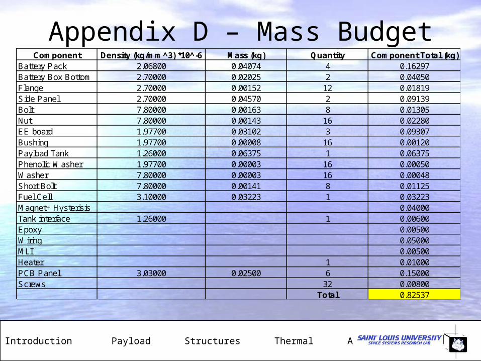
Appendix D – Mass Budget
Introduction Payload Structures Thermal ADCS Conclusions
Component Density (kg/mm^3) *10^-6 Mass (kg) Quantity Component Total (kg)Battery Pack 2.06800 0.04074 4 0.16297Battery Box Bottom 2.70000 0.02025 2 0.04050Flange 2.70000 0.00152 12 0.01819Side Panel 2.70000 0.04570 2 0.09139Bolt 7.80000 0.00163 8 0.01305Nut 7.80000 0.00143 16 0.02280EE board 1.97700 0.03102 3 0.09307Bushing 1.97700 0.00008 16 0.00120Payload Tank 1.26000 0.06375 1 0.06375Phenolic Washer 1.97700 0.00003 16 0.00050Washer 7.80000 0.00003 16 0.00048Short Bolt 7.80000 0.00141 8 0.01125Fuel Cell 3.10000 0.03223 1 0.03223Magnet+ Hysterisis 0.04000Tank interface 1.26000 1 0.00600Epoxy 0.00500Wiring 0.05000MLI 0.00500Heater 1 0.01000PCB Panel 3.03000 0.02500 6 0.15000Screws 32 0.00800
Total 0.82537
Appendix E – Cross Beam Vibs
Introduction Payload Structures Thermal ADCS Conclusions
Vibration of Beam on Side Panel Paul Lemon 11/30/06
3L 10.995608 4L 14.1371651L 4.730041 2L 7.853205
A 4mm 4mmb 4mm h 4mm 2.7
g
cm3
E 70 106
kg mm
s2
A 1.6 10
5 m2
Ib h
312
I 2.133 1011 m
4
L2 E I
A L4
1
2
L
2 2L2 70 10
6 21.33
2.7 106 16 83
4
1
2
2 5.263 104
1 1L2 70 10
6 21.33
2.7 106 16 83
4
1
2
f2
2
2
1 1.909 104
f2 8.376 103
f11
2
f1 3.039 103
4 4L2 70 10
6 21.33
2.7 106 16 83
4
1
2
3 3L
2 70 106 21.33
2.7 106 16 83
4
1
2
4 1.706 1053 1.032 10
5
f44
2
f33
2
f4 2.715 104
f3 1.642 104
Singiresu S. Rao. Mechanical Vibration 4th Edition. Prentice Hall, Inc.2004
Hz
Hz
HzHz

Appendix F – Component Vibs
Introduction Payload Structures Thermal ADCS Conclusions
Pro Mechanica Hand CalculationComponent Mode Natural Frequency (Hz) Natural Frequency (Hz)
Cross Bar Beam 1 3051 3039
2 3059 8376
3 9520 16420
4 10025 27150
Support Panel 1 2747.8
2 2760.69
3 2804.42
4 2810
Battery Box 1 1459.37
2 2701.97
3 2962.99
4 3234.84