bim enabled optimisation framework for environmentally ... · bim enabled optimisation framework...
TRANSCRIPT

BIM Enabled Optimisation Framework for Environmentally Responsible and Structurally Efficient Design Systems
Stathis Eleftheriadisa,d, Dejan Mumovica, Paul Greeningb, Angelos Chronisc
aUCL Institute of Environmental Design and Engineering, University College London, UK
bDepartment of Civil, Environmental & Geomatic Engineering, University College London, UK cBartlett School of Architecture, University College London, UK
dPrice & Myers Consulting Engineers, London, UK E-mail: [email protected]
ABSTRACT
The present research investigates the potential for reducing the environmental impacts of structural systems through a more efficient use of materials. The main objective of this research is to explore and to develop a holistic and integrated methodology that utilises Building Information Modelling’s (BIM) capabilities combined with structural analysis and Life Cycle Assessment (LCA) as well as a two-staged structural optimisation solver that achieves efficient and environmentally responsible steel design solutions. The implemented workflow utilises Autodesk Revit - BIM, Tally - LCA and Autodesk Robot - Structural Analysis. RobOpt is the plug-in that has been established using the Application Programming Interface (API) of Robot and the .NET framework of C♯, and it inherits several structural functionalities based on Robot Finite Element Method (FEM) engine. The proposed RobOpt application can be accessed via a graphic user interface (GUI) within the Robot software. The developed BIM-enabled optimisation methodology could be utilised as a design tool to inform early stage structural design solutions. A prototypical steel framed structural system under certain loads has been explored. The resulting bespoke I-beam sections from the custom genetic algorithm (GA) optimisation demonstrate that significant savings – up to 21% – can be achieved in all tested environmental indicators when compared to the standard UK catalogue of steel sections. Considering all, the proposed framework constitutes a useful and an intuitive workflow, which aims to quantify the environmental savings of structural systems by utilising, advanced computational analysis and common construction techniques.
Keywords - BIM; Structural Analysis; Steel Design Optimisation; Life Cycle Assessment
1 Introduction The building sector has been identified as a major
contributor to the global environmental impacts due to human activities [1, 2]. LCA has been used in building/construction sustainability evaluation since 1990 [3]. During the last 20 years, many LCA studies have focused on structural systems and have particularly investigated and calculated the environmental impacts of the associated building materials [4]. Comparative life cycle studies of building systems indicate that the choice of building structure affects the primary energy use and the greenhouse gas emissions of buildings. Assuming that a building is constructed from steel, a switch to a concrete design would reduce its annual CO2 emissions by approximately 750,000 tonnes [5]. Nonetheless, it is known that concrete and steel buildings use more energy than buildings made out of wood [6]. Although the operational energy is slightly lower for a concrete-framed building than for a wood-
framed one, the overall life cycle energy balance including the production, operation and end-‐of-‐life stages is lower for a wood-‐framed building compared to a concrete-‐framed alternative [7].
[8] have compared the environmental impacts of two different building structures: steel and concrete. They have found that during the life cycle of the tested steel-framed buildings, the energy consumptions and the environmental emissions of building materials per area are 24.9% when compared to the concrete-framed buildings. [9] have conducted a study to investigate the factors that have the highest contribution to the changes in energy and CO2 balances caused by variations in construction and use of concrete and timber framed buildings’ lifecycle. Throughout their research Gustavsson & Sathre have concluded that the materials of the timber-framed buildings have lower total energy and CO2 balance when compared to the concrete-framed ones in all tested scenarios but one. In addition, a study

undertaken by [10] focuses on load bearing masonry buildings. They compare a brickwork building to a soil-cement block building, and they show that the total embodied energy of load bearing masonry building could be reduced by 50% with the use of energy-efficient building materials. However, it has been observed that there is difficulty in analysing and comparing different LCA studies as the methods that were implemented to calculate the environmental impacts; the input-output data and the process analysis are often different [4].
While carbon reduction is a motivation for BIM policy, the connections between digital technologies and sustainability in practice are not well developed. Nevertheless, there is a research activity that is beginning to develop new tools, which implement BIM in order to address a range of sustainability-related concerns. The concerns addressed by such tools include: the assessment of environmental impacts [11], consideration of waste management issues [12, 13], guidance to designers on environmental issues [14, 15, 16, 17] and a response to a government strategy for carbon reductions in both current and future building stocks [18]. BIM models can be utilised to indicate an entire building life cycle [19] as the drawings, procurement details, submittal processes and other specifications can easily be interrelated [20]: data generated by BIM can be extracted and analysed to produce information, which can be used to make decisions and to improve design processes. The integration of BIM could increase the productivity, reduce errors, improve stakeholders’ participation and allow for data and information sharing among the project team members [21]. The success of BIM depends on many parameters, but as [22] suggested, the benefits of BIM can be quantified and summarised in two main categories based on the evaluation of tested cases: 1) Return metrics: change orders, Request For Information (RFI) and schedule, 2) Investment metrics: design fees and contractors’ costs. Integrating BIM with analytical tools is an emerging field, which has begun to attract attention within the academic community.
The preliminary studies’ outcomes are promising. [23] use BIM for building performance simulations and they focus on the integration of daylight analysis into a BIM environment. In a similar framework, [24] demonstrate the integration of thermal performance analysis into Revit using a Modelica-based thermal simulation engine by accessing Revit data and outputting Modelica code. [25] have also developed a prototypical tool integrated into BIM that enables real-time rapid energy and exergy calculations while also providing a graphical visualisation of key performance indicators. Moreover, [26] propose a BIM-based decision support method, which provides designers with
feedback regarding the environmental impacts of their early design decisions. The method integrates BIM, LCA, energy simulation, maintenance, repair, and replacement (MRR) scheduling along with sensitivity analysis software. In a similar framework, [27] propose a methodology, which evaluates the environmental impacts of buildings in China by identifying the need for an LCA software in order to perform a full Life Cycle Assessment. Furthermore, [28] have developed a BIM-based approach, which allows for a simplified estimation of a building’s life cycle environmental performance based on a predefined range of materials and construction options that lower the life cycle impacts and the energy consumption of that building. In a research conducted by [29], the interoperability problem between BIM-based LCC and energy optimisation has been investigated. Their approach utilises a BIM/GA-based framework that has the ability to identify and to classify various building components from a selected range, and minimise the Life Cycle Costs along with energy consumption. A BIM-based model that includes cost estimation has additionally been proposed by [30]. [31] have developed an optimisation system, which manages scheduling of important site-based construction processes. The 4D simulation function with the optimisation process includes data from the 3D model and predefined calculation formulas determining the amount of work required for the main construction operations.
The reduction of structural systems’ environmental impacts can be achieved using structural optimisation. Optimisation is an effective tool that is commonly used for structural design in order to synthesise the compliance of mechanisms. It is classified based on size, shape and topology [32]. Design optimisation methods have been implemented to obtain efficient and economic designs since 1970 [33, 34], which have led to the development of several algorithms from the early mathematical programming [35] techniques to advanced Heuristic and Metaheuristic methods [36]. In traditional engineering, numerous structural analysis algorithms have been implemented that address various optimisation problems such as economical designs, minimal deflections, etc. In today’s world where policy is trying to regulate the environmental impacts of buildings and where BIM has become a reality in the engineers’ design approach, the integration of BIM with an advanced structural optimisation algorithm seeking environmentally friendly solutions has become a necessity. [37] state that in addition to the environmentally friendly systems and materials, the reduction in CO2 emissions should be mitigated by the implementation of efficient material use in structural systems which can be achieved through optimisation methods.

2 Methodology In this research, the amalgamation of different
disciplines under the BIM umbrella has been explored using a computational approach, which combines structural analysis and optimisation along with the assessment of a structure’s environmental impacts.
2.1 Aims and Objectives The main objective of this research is to develop and
validate a holistic workflow, which includes BIM, structural analysis and LCA as well as an overall structural optimisation solver that seeks for structurally efficient and environmentally responsible steel design solutions. The main aims of the project’s multidisciplinary approach are identified in detail as the following:
1. To develop a BIM integrated optimisation
framework for structurally efficient and environmentally responsible steel structures,
2. To investigate the effectiveness of a distinct framework, which incorporates structural analysis, structural code verification, design optimisation and LCA,
3. To propose a multifunctional structural plug-in with customised GUI that acts as a buffer between the optimiser and the model within the BIM environment and the analysis model,
4. To implement a custom constraint GA as the main structural optimisation solver in order to increase the structural efficiency of I-beam sections,
5. To optimise and verify the structural instances of steel frame structures based on a specific design performance and Eurocode indicators,
6. To recommend alternative custom steel sections that minimise the overall environmental impacts of the tested model, and
7. To verify and demonstrate the methodology’s results and potential advantages for a prototypical steel-framed structure compared to standardised UK catalogue sections.
2.2 Integrated Workflow Figure 1 displays the diagram of the suggested
workflow with the integrated structural optimisation and the LCA components. By incorporating the structural efficiency and the environmental impacts’ analyses as parts of the BIM platform, multiple design solutions can be assessed by the design team, and a consensus can been achieved by analysing specific trade-offs along
with design objectives. It is therefore, expected that the explored optimisation solver provides a higher degree of integration and assists different stakeholders in implementing efficient structural measures. The optimisation solver shown in Figure 1 creates a buffer between different analyses and modelling tools that further enhance the capabilities of BIM. In detail, the objectives of the optimisation solver with the customised GA are:
1. To integrate interoperability of models between
BIM and structural analysis, 2. To validate the structural efficiency via an
integrated structural analysis and Eurocode verification, and
3. To evaluate the environmental impacts of the tested case via a BIM integrated LCA tool
Figure 1. Optimisation solver’s diagram showing enhanced design workflow
3 Software Architecture The explored methodology incorporates two main
analytical procedures and utilises BIM as the link between the two approaches: 1) Structural calculations and optimisation, and 2) LCA. The methodology includes Autodesk Revit 2014 as the BIM platform, Autodesk Robot 2014 as the structural analysis tool and Tally as the LCA software. A custom plug-in has been developed based on the Robot engine, which performs full structural analysis, verification and optimisation of steel framed structures. The API of Robot has been accessed by implementing C#, which is compliant with the .NET framework.
3.1 Model Description Autodesk Revit is the core of the design model, and
where all the building information is stored and where the team can exchange, download and upload drawings,

design information, policy requirements and design objectives. In regards to the 3D model description, two approaches can be applied: in the first one, the parametric 3D BIM model can be imported into Robot/RobOpt whereas in the second alternative, the 3D geometry can be generated and verified within Robot/RobOpt, and it can subsequently be transferred back into the BIM model. In the tested case study presented in this paper, the design flow follows the second approach, in which the user identifies a single bay steel-framed structural system with a set of 3D nodes’ coordinates. After the 3D model is defined in RobOpt, various structural inputs can further be assigned including load cases, steel sections and supports.
Using the Autodesk Robot engine, Eurocode verification can be performed for a design configuration, and the analysis can be visualised within RobOpt or it can be exported and processed within external applications. In RobOpt, the integrated GA optimisation engine searches for the custom I-beam section, which minimises the environmental impacts and maximises the efficiency ratio of the frame. The proposed custom steel section automatically updates the model in Robot and the new information model updates the BIM definition along with material quantities and properties. The embedded LCA analysis in Tally can then be established based on the BIM model, and in this manner, a full assessment or a series of comparative studies of the potential environmental impacts can be performed.
3.2 RobOpt GUI The developed RobOpt application is a plug-in for
Robot that utilises structural steel design analysis and performance indicators with an embedded visualisation tool as well as Eurocode verification capabilities and a custom steel section GA optimisation solver in one compact package. The GUI of the plug-in is shown in Figure 2; with 9-implemented different functionalities and the corresponding grouped panels. The application utilises the FEM engine of Robot, and it enables the communication between the 3D environment interface and the RobOpt operational panels by integrating text boxes, buttons and mouse interaction. The user can 1) build a structural frame system, 2) assign steel sections from the UK hot rolled sections’ database, 3) define supports, 4) determine the load cases, 5) run the structural analysis, 6) plot and export the calculations’ results including forces, reactions, deflections and material quantities, 7) perform Eurocode verification/optimisation among available steel member groups, 8) customise I-beam sections, 9) execute GA optimisation for custom steel sections, and export a .csv file of the results.
Figure 2. Proposed RobOpt GUI
3.3 Prototypical Steel System The structural system that can be populated via
RobOpt consists of two main components: the nodes and the bars. The nodes are represented by a set of x, y, z coordinates within the Robot’s 3-D space, and the 2 adjacent node coordinates define the bars. The user can manually determine the structural system’s topology by adding the nodes’ coordinates. The application also has the ability to accommodate a parametrically based geometric definition, which allows a large set of geometric topologies to be investigated and articulated from mathematically based representations. However, for the purposes of this project, a fixed geometry has been studied: the geometric definition that has been used as a prototypical case consists of a frame of 5m width, 5m length and 3m height (Figure 3). After the geometry is generated, RobOpt automatically assigns the nodes’ and the bars’ definitions that are going to be implemented within the structural performance calculations.
Figure 3. Prototypical steel frame model with random steel sections in the Robot environment

Following the geometry’s definition, the user assigns a steel section to the corresponding bars (- beams and columns) from the UK standard sections’ database. In this case, commonly used UB sections are applied to the beams, and Circular Hollow Sections (CHS) are assigned to the model’s columns. In regards to the supports, which join the superstructure with their foundation, the user selects between roller, pinned or fixed connections from the corresponding panel. Three load cases are implemented in RobOpt: 1) Self-weight, 2) Live, 3) Wind Loads. The load cases’ step includes two main phases: 1) Bars and load selection, and 2) Load case definition. In the first phase, the user selects the structural members, to which the loads are applied to by clicking on the radio button in the load cases’ interface and by using the mouse in the model. After the load cases and the members are identified, the user applies numerical values to the loads’ definition and can feed back the information to the Robot model by clicking the “Create Load Cases” button. Subsequent to the structural frame’s, the steel sections’, the load cases’ and the supports’ assignments are identified, the user can perform the structural analysis using the “Run Calculations” button. In addition, visualisation functionalities have also been implemented within RobOpt in order to allow the user to plot the results from the structural analysis within the application: the user can plot the forces (Fx, Fy, Fz, Mx, My, Mz), the reactions (Fx, Fy, Fz, Mx, My, Mz), the deflections (Ux, Uy, Uz) and the material quantities from the defined structural frame in the designated tabs of the visualisation interface, and he/she can also export the graphs in .jpg format.
4 Design Optimisation Utilising the Robot engine in the core of the
application enables the verification of the steel members based on the Eurocode, BS-EN 1993-1:2005/NA: 2008/AC: 2009. A custom GA script in C# has been integrated within the GUI in order to perform structural optimisation. The user can manually specify the GA’s parameters such as mutation rate, number of population and maximum generations.
4.1 Model Calibration The GA code has been calibrated for its performance
in a series of basic instances, which investigate the steel frame structure’s overall weight and its utilisation ratio. The utilisation ratio demonstrates the structure’s excess capacity, i.e. the material that is unnecessary [38]. The total environmental emissions are calculated by multiplying the material quantities of all the structural members with the corresponding emissions’ intensities.
The structural weight is linked to the optimisation solver and the emission factors to Tally’s LCI database. The steel beams’ parameters represent the GA’s four genes, which comprise of the algorithm’s inputs. In particular, the section’s Depth d and Width B, as well as the Flange’s Thickness T and the Web’s Thickness t are allowed to vary between the ranges displayed on Table 1.
Table 1. Steel beam sections’ specified ranges for GA
Design Inputs Genes Minimum
(mm) Maximum
(mm) Depth d 1 130 175 Width B 2 90 125 Flange
Thickness T 3 4 6.5
Web Thickness t 4 4 6.5
The fitness function is equivalent to the structure’s
overall weight, and it appears to have a constant declining trend while the algorithm searches the design space for the optimum solution until it converges to an overall weight of 362kg. Figure 4 indicates a good approximation of the algorithm for finding the fitness function’s minimum value after about 500 generations with a relative error of nearly 1.4%.
Figure 4. The GA’s convergence results of all varying design inputs
4.2 Preliminary Remarks In addition to the calibration, the obtained results
also provide useful insight regarding the structural performance of the prototypical design system. The conflicting behaviour between the overall weight and the efficiency ratio of the tested structure has been identified. Figure 5 shows the general mapping of the structural weights and the corresponding efficiency ratios. It has been observed that the higher the weight of the structure is, the stiffer it becomes and therefore, it presents less efficiency in terms of material use. On the other hand, the cases with higher efficiency ratios tend
350 360 370 380 390 400 410 420 430 440 450 460 470 480 490 500 510 520 530 540
1 51 101 151 201 251 301 351 401 451 501 551 601 651 701
Wei
ght (
kg)
Number of Generations
Wei
ght (
kg)
Number of Generations
to have a reduced structural weight, meaning that the use of materials is more effective. In the highlighted area of Figure 5, it can be seen that there are sections outside the maximum permitted efficiency ratio. These sections will therefore, not be acceptable which leads to additional restrictions within the fitness function.
Figure 5. Conflicting nature of structural efficiency and structural weight
A constraint method that penalises the infeasible
solutions has been implemented: a constant penalty to the solutions that violate the Eurocode’s slenderness constraints is applied. The penalty function for the minimisation problem with m constraints is shown in Equation (1).
𝑓𝑝 𝑥 = 𝑓 𝑥 + 𝐶𝑖𝛿𝑖!
!!! (1) The effectiveness of the penalisation functionality
can be summarised in Figure 6, where the efficiency ratio sporadically exceeds the maximum value of 1 during the early generations, and the algorithm, after approximately 350 generations, converges to the maximum ratio of 0.999, which is equivalent to a minimum structural weight of 380kg. In this manner the algorithm penalises the solutions with an efficiency ratio greater than 1 and gradually eliminates them from the final population.
Figure 6. Optimisation results with penalisation
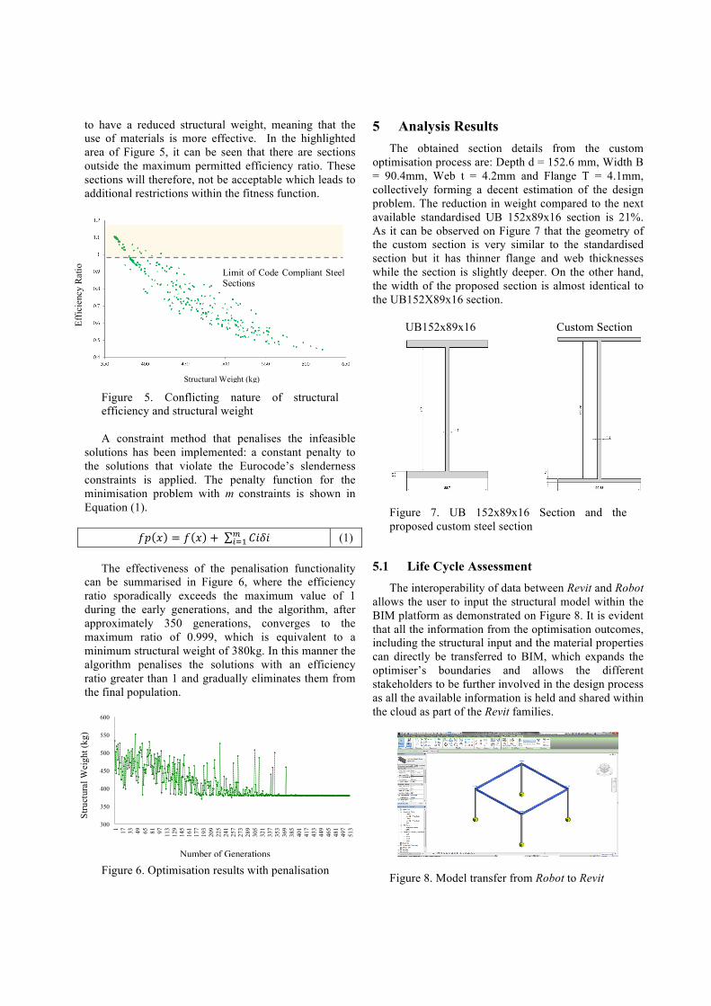
5 Analysis Results The obtained section details from the custom
optimisation process are: Depth d = 152.6 mm, Width B = 90.4mm, Web t = 4.2mm and Flange T = 4.1mm, collectively forming a decent estimation of the design problem. The reduction in weight compared to the next available standardised UB 152x89x16 section is 21%. As it can be observed on Figure 7 that the geometry of the custom section is very similar to the standardised section but it has thinner flange and web thicknesses while the section is slightly deeper. On the other hand, the width of the proposed section is almost identical to the UB152X89x16 section.
UB152x89x16 Custom Section
Figure 7. UB 152x89x16 Section and the proposed custom steel section
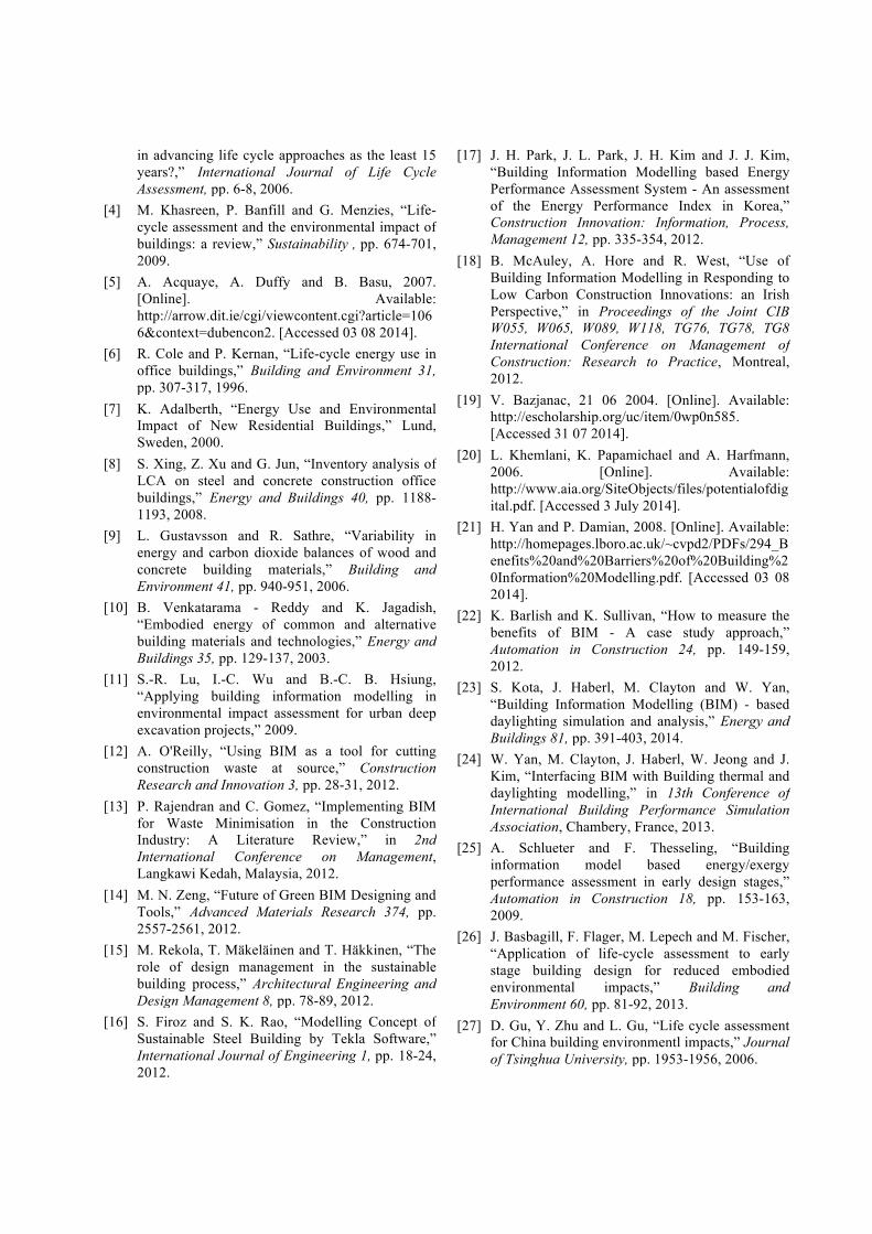
5.1 Life Cycle Assessment The interoperability of data between Revit and Robot
allows the user to input the structural model within the BIM platform as demonstrated on Figure 8. It is evident that all the information from the optimisation outcomes, including the structural input and the material properties can directly be transferred to BIM, which expands the optimiser’s boundaries and allows the different stakeholders to be further involved in the design process as all the available information is held and shared within the cloud as part of the Revit families.
Figure 8. Model transfer from Robot to Revit
300
350
400
450
500
550
600
1 17
33
49
65
81
97
113
129
145
161
177
193
209
225
241
257
273
289
305
321
337
353
369
385
401
417
433
449
465
481
497
513
Stru
ctur
al W
eigh
t(kg
)
Number of Generations
Limit of Code Compliant Steel Sections
Effic
ienc
y R
atio
Structural Weight (kg)
Number of Generations
Stru
ctur
al W
eigh
t (kg
)

LCA is an assessment tool, which quantifies potential environmental impacts of a product, process or of a system during its lifetime and it includes raw material extraction, production, operation, and end-of-life [39]. Both entries, the UB152x89x16 and the custom steel section were evaluated in terms of their potential environmental impacts in Tally. Tally methodology is consistent with the LCA standards of ISO 14040:2006 and 14044:2006. The LCA results represent the analysis of a prototypical structural system. A consistent reduction in all of the related environmental indicators; Global Warming Potential (GWP kgCO2eq), Eutrophication Potential (EP kg N eq), Ozone Depletion Potential (ODP kg CFC-11 eq) and Acidification Potential (AP kg SO2 eq) has been observed for the proposed custom section: the largest reduction of approximately 21% has been identified in the GWP measurements, whereas the smallest reduction has been detected for the AP with 19% reduction compared to the UB152x89x16 section. In his study, [40] has also quantified reductions of approximately 21-24% when using a customised section beam instead of a catalogue one.
In the tested scenario with RobOpt, the manufacturing process for both the custom and the standard sections have been considered as hot-rolled at this stage of the research. [41] have expanded the capabilities of hot-rolling processes with minimal yield losses by investigating the potential development of I-sections with varying depths. However, cutting steel plates to the desired thicknesses and welding them back together could be an alternative production technique for the custom sections. The proposed design methodology in this research is the initial stage of a larger investigation and therefore, requires further work in order to assess the framework’s generality. A broad spectrum of design configurations should be investigated in order to examine whether custom steel sections’ classification could offer potential weight reduction and environmental savings in real-life projects. This could be achieved by comparing existing steel-framed case studies and by testing their potential savings. Additional LCA studies could analyse the impact of different manufacturing processes in terms of overall environmental weights. Furthermore, a comparative LCA and LCC analysis would provide detailed performance metrics in terms of environmental and cost implications for the custom steel sections compared to the standard sections throughout a building’s life cycle. This will suggest whether the existing catalogue of standardised sections could be enhanced with additional beam sections, which will enable the designers to offer robust solutions that improve the structural efficiency and the environmental performance of their designs.
6 Conclusions A parametric optimisation framework has been
explored and established to perform and analyse both a structure’s efficiency and its environmental performance as part of a holistic BIM approach. This methodology is achieved through coupling various simulation tools. However, in this study’s approach it is integrated into a single platform, in which all design variables can be manually controlled. A key component of the developed methodology is the custom RobOpt application, which is implemented to perform all of the structural design operations and the Eurocode verification. RobOpt allows for a rapid manipulation of input parameters in order to analyse different cases, and it provides feedback via integrated visualisation analysis results and a 3-dimensional representation of the structural model. In addition, RobOpt creates a buffer between the parametric BIM model and a user-friendly LCA. The proposed methodology has been validated through a case study simulation of a prototypical steel framed structural system. For the tested design configuration, the resulted custom I-section from the GA optimisation demonstrates that significant savings – up to 21% – can be achieved in the overall structural weight and in all of the tested environmental indicators – GWP, ODP, EP and AP – when compared to the standard UK catalogue steel sections. The created application is easily expandable and customisable through the inclusion of more connected components or even new user-defined applications within the BIM environment, which could be utilised as a design tool to inform early stage, efficient structural design solutions.
Acknowledgments This research has been made possible through
funding provided by the Engineering and Physical Sciences Research Council (EPSRC) and from Price & Myers LLP, and this is gratefully acknowledged here.
References
[1] I. Z. Bribian, A. Uson and S. Scarpellini, “Life cycle assessment in buildings: State-of-the-art and simplified LCA methodology as a complement for building certification,” Building and Environment 12, pp. 2510-2520, 2009.
[2] S. Junnila and A. Horvath, “Life-Cycle Environmental Effects of an Office Building,” Journal of Infrastructure Systems 9, pp. 157-166, 2003.
[3] J. Fava, “Will the next 10 years be as productive
in advancing life cycle approaches as the least 15 years?,” International Journal of Life Cycle Assessment, pp. 6-8, 2006.
[4] M. Khasreen, P. Banfill and G. Menzies, “Life-cycle assessment and the environmental impact of buildings: a review,” Sustainability , pp. 674-701, 2009.
[5] A. Acquaye, A. Duffy and B. Basu, 2007. [Online]. Available: http://arrow.dit.ie/cgi/viewcontent.cgi?article=1066&context=dubencon2. [Accessed 03 08 2014].
[6] R. Cole and P. Kernan, “Life-cycle energy use in office buildings,” Building and Environment 31, pp. 307-317, 1996.
[7] K. Adalberth, “Energy Use and Environmental Impact of New Residential Buildings,” Lund, Sweden, 2000.
[8] S. Xing, Z. Xu and G. Jun, “Inventory analysis of LCA on steel and concrete construction office buildings,” Energy and Buildings 40, pp. 1188-1193, 2008.
[9] L. Gustavsson and R. Sathre, “Variability in energy and carbon dioxide balances of wood and concrete building materials,” Building and Environment 41, pp. 940-951, 2006.
[10] B. Venkatarama - Reddy and K. Jagadish, “Embodied energy of common and alternative building materials and technologies,” Energy and Buildings 35, pp. 129-137, 2003.
[11] S.-R. Lu, I.-C. Wu and B.-C. B. Hsiung, “Applying building information modelling in environmental impact assessment for urban deep excavation projects,” 2009.
[12] A. O'Reilly, “Using BIM as a tool for cutting construction waste at source,” Construction Research and Innovation 3, pp. 28-31, 2012.
[13] P. Rajendran and C. Gomez, “Implementing BIM for Waste Minimisation in the Construction Industry: A Literature Review,” in 2nd International Conference on Management, Langkawi Kedah, Malaysia, 2012.
[14] M. N. Zeng, “Future of Green BIM Designing and Tools,” Advanced Materials Research 374, pp. 2557-2561, 2012.
[15] M. Rekola, T. Mäkeläinen and T. Häkkinen, “The role of design management in the sustainable building process,” Architectural Engineering and Design Management 8, pp. 78-89, 2012.
[16] S. Firoz and S. K. Rao, “Modelling Concept of Sustainable Steel Building by Tekla Software,” International Journal of Engineering 1, pp. 18-24, 2012.
[17] J. H. Park, J. L. Park, J. H. Kim and J. J. Kim, “Building Information Modelling based Energy Performance Assessment System - An assessment of the Energy Performance Index in Korea,” Construction Innovation: Information, Process, Management 12, pp. 335-354, 2012.
[18] B. McAuley, A. Hore and R. West, “Use of Building Information Modelling in Responding to Low Carbon Construction Innovations: an Irish Perspective,” in Proceedings of the Joint CIB W055, W065, W089, W118, TG76, TG78, TG8 International Conference on Management of Construction: Research to Practice, Montreal, 2012.
[19] V. Bazjanac, 21 06 2004. [Online]. Available: http://escholarship.org/uc/item/0wp0n585. [Accessed 31 07 2014].
[20] L. Khemlani, K. Papamichael and A. Harfmann, 2006. [Online]. Available: http://www.aia.org/SiteObjects/files/potentialofdigital.pdf. [Accessed 3 July 2014].
[21] H. Yan and P. Damian, 2008. [Online]. Available: http://homepages.lboro.ac.uk/~cvpd2/PDFs/294_Benefits%20and%20Barriers%20of%20Building%20Information%20Modelling.pdf. [Accessed 03 08 2014].
[22] K. Barlish and K. Sullivan, “How to measure the benefits of BIM - A case study approach,” Automation in Construction 24, pp. 149-159, 2012.
[23] S. Kota, J. Haberl, M. Clayton and W. Yan, “Building Information Modelling (BIM) - based daylighting simulation and analysis,” Energy and Buildings 81, pp. 391-403, 2014.
[24] W. Yan, M. Clayton, J. Haberl, W. Jeong and J. Kim, “Interfacing BIM with Building thermal and daylighting modelling,” in 13th Conference of International Building Performance Simulation Association, Chambery, France, 2013.
[25] A. Schlueter and F. Thesseling, “Building information model based energy/exergy performance assessment in early design stages,” Automation in Construction 18, pp. 153-163, 2009.
[26] J. Basbagill, F. Flager, M. Lepech and M. Fischer, “Application of life-cycle assessment to early stage building design for reduced embodied environmental impacts,” Building and Environment 60, pp. 81-92, 2013.
[27] D. Gu, Y. Zhu and L. Gu, “Life cycle assessment for China building environmentl impacts,” Journal of Tsinghua University, pp. 1953-1956, 2006.

[28] H. Gervásio, P. Santos, R. Martins and L. Simões da Silva, “A macro-component approach for the assessment of building sustainability in early stages of design,” Building and Environment 73, pp. 256-270, 2014.
[29] M. Nour, O. Hosny and A. Elhaheem, “A BIM based Energy and Lifecycle Cost Analysis/Optimisation Approach,” International Journal of Engineering Research and Applications, pp. 411-418, 2012.
[30] F. Cheung, J. Rihan, J. Tah, D. Duce and E. Kurul, “Early stage multi-level cost estimation for schematic BIM models,” Automation in Construction 27, pp. 67-77, 2012.
[31] S. Song, J. Yang and N. Kim, “Development of a BIM-based structural framework optimization and simulation system for building construction,” Computers in Industry 63, pp. 895-912, 2012.
[32] M. Bensdoe and O. Sigmund, Topology optimisation: Theory, Methods and Applications, Springer, 2002.
[33] F. Glover, “Heuristic for integer programming using surrogate constraints,” Decision Sciences, pp. 156-166, 1977.
[34] M. Pincus, “ Monte Carlo method for the approximate solution of certain types of constrained optimization problems,” Operation Resources 18, pp. 1225-1228 , 1970.
[35] M. Jahjouh, “Design Optimization of Reinforced Concrete Frames using Artificial Bee Colony Algorithm, Master's Thesis,” The Islamic University of Gaza , Gaza, Palestine, 2012.
[36] W. Jenkins, “Towards structural optimization via the genetic algorithm,” Computers and Structures 40, pp. 1321-1327, 1991.
[37] I. Paya-Zaforteza, V. Yepes, A. Hospitaler and F. González-Vidosa, “CO2-optimization of reinforced concrete frames by simulated annealing,” Engineering Structures 31, pp. 1501-1508, 2009.
[38] M. Moynihan and J. Allwood, “Utilization of structural steel in buildings,” Proceedings of the Royal Society, vol. 470, 2014.
[39] ISO 14040, “ISO 14040 International Standard in Environmental Management - Life Cycle Assessment - Principles and Framework,” International Organisation for Standardization, Geneva, Switzerland, 2006.
[40] Thirion, C. (2012). Putting the material in the right place, Master's Thesis. London, UK: UCL.
[41] M. Carruth and J. Allwood, “The development of
hot rolling process for variable cross section I-beams,” Journal of materials processing technology, pp. 1640-1653, 2012.