binder cover sheet-pw - pumpworks · familiarization with the product and its permitted ......
TRANSCRIPT


Page 2 of 29 Model: PWM & PWM-D Rev. C_8/21/2015
INSTALLATION OPERATION & MAINTANENCE
Model: PWM & PWM-D

Page 3 of 29 Model: PWM & PWM-D Rev. C_8/21/2015
TABLE OF CONTENTS INTRODUCTION Company Details ........................................................................................................................................ 4 Declaration of Conformity ........................................................................................................................... 5 Scope ................. .......................................................................................................................................6 Description ................................................................................................................................................. 6 General ....................................................................................................................................................... 6 Safety ...................................................................................................................................................... 6-9 CE and ATEX marking and approvals ..................................................................................................... 10 Disclaimer................................................................................................................................................. 10 Copyright .................................................................................................................................................. 10 Design Performance ................................................................................................................................ 10 Duty Conditions ................................................................................................................................... 10-11 Specific Gravity ........................................................................................................................................ 11 Speed ....................................................................................................................................................... 11 NPSH ....................................................................................................................................................... 11
INSTALLATION Receiving Inspection ................................................................................................................................ 11 Short Term Storage ............................................................................................................................. 11-12 Long Term Storage .................................................................................................................................. 12 Foundation ......................................................................................................................................... 12-13 Leveling .................................................................................................................................................... 13 Grouting .................................................................................................................................................... 13 Piping Recommendations ................................................................................................................... 13-14 Lifting ........................................................................................................................................................ 14 Pump Installation ................................................................................................................................. 14-15 Driver Installation ..................................................................................................................................... 15 Alignment ............................................................................................................................................ 15-16 Couplings ................................................................................................................................................. 16 Lubrication .......................................................................................................................................... 16-18 Recommended Control Settings ............................................................................................................. 19 Pre-Startup Procedures ..................................................................................................................... 19-20 Startup Procedures .................................................................................................................................. 20 Startup Inspection .................................................................................................................................... 20 Shutdown ................................................................................................................................................. 21 Extended Shutdown ................................................................................................................................. 21
MAINTENANCE Preventative Maintenance ................................................................................................................... 21-22 Mechanical Seal / Bearing Housing Removal ..................................................................................... 22-26 Remaining Un-Drained Product .......................................................................................................... 25-26 Rotating Element Removal ................................................................................................................. 26-27
TROUBLESHOOTING Troubleshooting .................................................................................................................................. 28-29
REVISIONS Revisions .................................................................................................................................................. 29

Page 4 of 29 Model: PWM & PWM-D Rev. C_8/21/2015
INTRODUCTION
COMPANY DETAILS MANUFACTURER:
PUMPWORKS 610 P.O. Box 19606 Shreveport, LA 71149
DESCRIPTION OF EQUIPMENT:
Centrifugal API 610 / ISO 13709 pumps for petroleum refinery, gas processing, oil processing, petrochemical, hydrocarbon and crude oil pipeline, offshore installations (platform) and aviation jet
fueling. MARKING OF MACHINERY
All machinery is marked visibly with: — the business name and full address of the manufacturer — Model — Size — ATEX Marking — Serial number — The year construction was completed

Page 5 of 29 Model: PWM & PWM-D Rev. C_8/21/2015
Declaration of Incorporation (Machinery)
EC Declaration of Conformity (ATEX) MANUFACTURER: PumpWorks 610 PRODUCT DESCRIPTION: PWM 8 x 10 x 13HE 8-STAGE PART NUMBER: 00.000126 DATE MANUFACTURED: 01/14/15 APPLICABLE EUROPEAN DIRECTIVES:
ATEX: 94/9/EC MD: 06/42/EC PED : 97/23/EC
APPLICABLE INTERNATIONAL STANDARDS:
MD: EN 12100:2010, ISO 13709: 2009, API 610: Sept 2010, ANSI-HI:1.6-2000, ANSI S75-19: Nov 1995 ATEX: EN 1127-1:2011, EN 13463-1:2009, EN 13463-5:2011 PED: ASME BOILER AND PRESSURE VESSEL CODE SECTION 2 PARTS A, B, C, AND D; SECTION 5;SECTION 8; AND SECTION 9, NACE RP 176
ATEX marking: II 2 G c T3 7060-2015-CE-USA
DNV Nemko Presafe AS, ATEX NB 2460 retains a copy of the Technical File The product described in this EC Declaration of Conformity complies with the applicable European Directives and relevant sections of the Applicable International Standards. Integration instructions are provided that contain requirements and specifications that must be implemented prior to putting this equipment into service. The signature on this document authorizes the distinctive ATEX marking to be applied to this equipment. All EHSR’s related to this equipment have been addressed; a Technical Construction File is available for inspection by designated bodies. Authorized Signature: Date:
Important safety information is contained in the installation, operation and service manuals; read and understand this information prior to installing or using this equipment
This Document applies only to the equipment described above and is invalid if not reproduced in its entirety.
Page 6 of 29 Model: PWM & PWM-D Rev. C_8/21/2015
SCOPE These instructions must always be kept near
the product's operating location or directly with the product.
This manual provides instructions for the installation, alignment, startup, and maintenance of the PumpWorks 610 PWM and PWM-D model pumps. This manual is used in combination with cross sections, general arrangement drawings, and instructions specific to each pump.
This manual should be read in its entirety, prior to the installation, alignment, operation and
maintenance of the unit in any region worldwide. The unit must not be put into service until all of the conditions relating to safety, that are noted in this manual, have been met.
PumpWorks 610 shall not be held liable for physical injury, damage to equipment or property, or delays caused by failure to read and observe all warnings in this Installation, Operation, and Maintenance Manual.
PumpWorks 610 shall not be held liable for injury or damage caused by the use of non-PumpWorks 610 parts.
DESCRIPTION The PWM is an API 610 type BB3 design -
axially split, between bearing, multistage pump. The PWM is a horizontally split, side suction, side discharge, double volute, opposed impeller design with a median stage crossover. The PWM-D model designates a double suction 1st stage impeller.
The PWM utilizes three choices of bearing housing designs:
Ball Radial – Ball Thrust Sleeve Radial – Ball Thrust Sleeve Radial – Tilting Pad Thrust
GENERAL These instructions are intended to facilitate
familiarization with the product and its permitted use. Operating the product in compliance with these instructions is important to help ensure reliability in service and avoid risks. The instructions may not take into account local
regulations; ensure such regulations are observed by all, including those installing the product. Always coordinate repair activity with operations personnel, and follow all plant safety requirements, applicable safety and health laws/regulations.
SAFETY SAFETY SYMBOLS
The following symbols are to be observed by the user. Non-observance would result in hazards, physical injury, damage or delays.
This symbol indicates electrical hazards where non-compliance of instructions will involve a high risk to personal safety or the loss of life.
This symbol indicates danger, warnings and caution where non-compliance of instructions would affect personal safety, could result in loss of life and involve some risk to safe
operation and personal safety and would damage the equipment or property.
This symbol indicates hazardous and or toxic fluid where non-compliance of instructions would affect personal safety and could result in loss of life.
This symbol indicates explosive atmosphere zone according to ATEX. It is used in safety instructions where non-compliance in the hazardous area would cause the risk of an explosion.

GENERAL SAFETY
Always follow proper lock out tag out procedures, on all potential energy sources, when servicing this equipment.
This equipment may be remotely operated and may startup automatically, without any warning.
This unit is a pressure vessel and contents are under pressure. Never try to tighten any fluid connections while this unit is running or pressurized.
This unit could be pumping potentially hazardous, flammable, explosive, hot, or corrosive product. Extreme caution and safety precautions should be used when servicing this equipment.
Always keep the work area clean and avoid excessive dust buildup on potentially hot surfaces.
Pay attention to the risks presented by gas and vapors in the work area.
Never run a pump with a closed suction, or closed discharge valve.
Never run a pump dry, below minimum flow, or if not properly primed.
Never use heat or an open flame when servicing this equipment, due to a potential explosion hazard.
Never change the service of this pump, for which it was designed, without consulting PumpWorks 610.
Never run this unit without sufficient or proper lubrication.
Never operate this equipment without all guards in place.
Never operate this equipment without all safety devices installed and operational.
Avoid all electrical dangers. Pay attention to the risks of electric shock or arc flash hazards.
Always bear in mind the risk of electrical accidents, and burn injuries.
Be aware of any and all risk of injury arising from contact with or in proximity of machinery/parts/materials that are at very high or very low temperatures. Take necessary steps to protect oneself or others.
Noise produced by pump is less than 85 dB(A). Surrounding environment may produce noise exceeding 85 dB(A). Hearing protection should be worn when required.
Use only good working non-rusted tools. Impact between light metals (aluminum) and rusty steel can cause a spark.
SAFETY EQUIPMENT
Use safety and personal protective equipment according to the users company regulations at all times when working around this equipment. This includes:
Head Protective Gear Eye Protection Foot Protection Gloves Hearing Protection
In other hazardous environments, additional personnel protective equipment may be required:
Flame Retardant Clothing
Respirators Breathing Apparatus Hazardous Environment Monitors Etc.
A first aid kit should be available.
The operator should be familiar with the use of fire extinguishers and note the location of the nearest fire equipment to the work area.
Electrical connections must be made by certified electricians in compliance with all

Page 8 of 29 Model: PWM & PWM-D Rev. C_8/21/2015
international, national, state, and local regulations.
SAFETY PRECAUTIONS BEFORE WORK IS STARTED
The operator must be aware of safety precautions to prevent physical injury.
Any pressure-containing device can explode, rupture, or discharge its contents if it is over-pressurized. Take all necessary measures to avoid over-pressurization.
Do not try to loosen or tighten any leaking fitting or connection while the unit is under pressure.
Operating, installing, or maintaining the unit in any way that is not covered in this manual could cause death, serious personal injury, or damage to the equipment. This includes any modification to the equipment or use of parts not provided by PumpWorks 610. If there is a question regarding the intended us of the equipment, please contact a PumpWorks 610 representative before proceeding.
This manual clearly identifies accepted methods for disassembling units. These methods must be adhered to. Trapped liquid can rapidly expand and result in a violent explosion and injury. Never apply heat to impellers, propellers, or their retaining devices to aid in their removal unless explicitly stated in this manual.
If the pump/motor is damaged or leaking, do not operate as it may cause an electric shock, fire, explosion, liberation of toxic fumes, physical harm, and/or environmental
damage. Correct/repair the problem prior to putting back it back into service.
Do not change the service application without the approval of an authorized PumpWorks 610 representative.
Provide a suitable barrier around the work area, for example, a guard rail.
Make sure that all safety guards are in place and secure.
Make sure that you have a clear path of retreat.
Make sure that the product cannot roll or fall over and injure people or damage property.
Make sure that the lifting equipment is in good condition.
Make sure lifting equipment is properly rated for unit weight. Refer to General Arrangement Drawings.
Allow all system and pump components to cool before you handle them.
Make sure that the product has been thoroughly cleaned.
Disconnect and lock out tag out all energizing sources before you service this equipment.
Check the explosion risk before you weld or use electric hand tools.
SAFETY PRECAUTIONS WHILE WORKING
Never weld to the exterior of the casing without proper weld procedures and post weld inspections and testing.
Never work alone
Always wear protective clothing and hand protection.
Stay clear of suspended loads.
Always lift the product by its lifting device.
This equipment may startup automatically, without any warning.
Properly clean components after you disassemble the pump.
Do not exceed the maximum allowable working pressure of the pump.

Page 9 of 29 Model: PWM & PWM-D Rev. C_8/21/2015
Do not open any vent or drain valve or remove any plugs while the system is pressurized. Make sure that the pump is isolated from the system and that pressure is relieved before
disassembly of the pump, remove plugs, or disconnect piping.
Never operate a pump without a properly installed coupling guard.
HAZARDOUS LIQUIDS
When the pump is handling hazardous liquids care must be taken to avoid exposure to the liquid. The PWM pump casing cannot be completely drained, so care must be taken when the pump is being removed for servicing, to blind flanges to prevent release of hazardous
products, until the pump can be properly flushed and/or cleaned. Appropriate precautions should be taken to limit access only to trained personnel. If the liquid is flammable and /or explosive, strict safety procedures must be applied.
HOT SURFACE IGNITION TEMPERATURE OF DUST LAYERS
Hot surfaces can ignite dust and dust buildup. Under normal operating conditions, surfaces, such as the bearing housings and pump casing, are well below the ignition temperature of any dust buildup. If a catastrophic failure of this unit were to occur, as due to a loss of lubrication or a loss of flow, surface temperatures of the housings or casing could exceed this level.
Therefore, dust buildup on any surface should be limited to a maximum of 1/8”. If the
buildup exceeds this, the unit should be properly shut down and cleaned. Proper lockout tag out procedures and safety precautions should be followed.
It is the responsibility of the end user to utilize safety equipment to monitor the product, and sleeve bearing temperatures.
Temperature monitoring devices are available by customer request if not already purchased and installed.
PERSONNEL QUALIFICATIONS AND TRAINING
These are the personnel requirements for Ex-approved products in potentially explosive atmospheres:
All work on the product must be carried out by certified electricians and PumpWorks 610-authorized mechanics. Special rules apply to installations in explosive atmospheres.
All users must know about the risks of electric current and the chemical and physical characteristics of the gas, the vapor, or both present in hazardous areas.
Any maintenance for Ex-approved products must conform to International and National Standards.
PumpWorks 610 shall not be held responsible for work done by untrained and
unauthorized personnel. All personnel involved in the operation, installation, inspection and maintenance of the unit must be qualified to carry out the work involved. If the personnel in question do not already possess the necessary knowledge and skill, appropriate training and instruction must be provided. If required, the operator may commission the manufacturer/supplier to provide applicable training. Always coordinate repair activity with operations and health and safety personnel, and follow all plant safety requirements and applicable safety and health laws and regulations.

Page 10 of 29 Model: PWM & PWM-D Rev. C_8/21/2015
CE AND ATEX MARKINGS AND APPROVALS It is a legal requirement that machinery and
equipment put into service within certain regions of the world shall conform with the applicable ATEX Marking Directives covering Machinery and, where applicable, Low Voltage Equipment, Electromagnetic Compatibility (EMC), Pressure Equipment Directive (PED) and Equipment for Potentially Explosive Atmospheres (ATEX). Where applicable the Directives and any additional Approvals cover important safety
aspects relating to machinery and equipment and the satisfactory provision of technical documents and safety instructions. Where applicable this document incorporates information relevant to these Directives and Approvals. To confirm the approvals applying and if the product is CE marked, check the serial number plate markings and the Certification, see section 9, Certification.
DISCLAIMER Information in these User Instructions is
believed reliable. In spite of all the efforts of PumpWorks 610 to provide sound and all necessary information, the content of this manual may appear insufficient and is not guaranteed by PumpWorks 610 as to its completeness or accuracy.
PumpWorks 610 manufactures products to International Standards Organization as certified and audited by external Quality Assurance organizations. Genuine parts and accessories have been designed, tested and incorporated into the products to help ensure their continued
product quality and performance while in use. As PumpWorks 610 cannot test parts and accessories sourced from other vendors the incorrect incorporation of such parts and accessories may adversely affect the performance and safety features of the products. The failure to properly select, install or use authorized PumpWorks 610 parts and accessories is considered misuse. Damage or failure caused by misuse is not covered by PumpWorks 610’s warranty. In addition, any modification of PumpWorks 610 products or removal of original components may impair the safety of these products in their use.
COPYWRIGHT All rights reserved. No part of these
instructions may be reproduced, stored in a retrieval system or transmitted in any form or by
any means without prior permission of PumpWorks 610.
DESIGN PERFORMANCE The PWM pump is specifically designed to
meet performance conditions based on service, operating speed, specific gravity, viscosity, and NPSHA. Materials of construction and running clearances are based on those conditions.
PumpWorks 610 Engineering Department should be consulted prior to changes in product or operating conditions beyond that of which this unit was specifically designed.
DUTY CONDITIONS This product has been selected to meet the
specifications of your purchase order. The acknowledgement of these conditions has been
sent separately to the Purchaser. A copy should be kept with these instructions.

Page 11 of 29 Model: PWM & PWM-D Rev. C_8/21/2015
The product in no way should be operated beyond the parameters specified for the application. If there is any doubt as to the suitability of the product for the application intended, contact PumpWorks 610 for advice, referencing the serial number.
If the conditions of service on your purchase order are going to be changed, (for example liquid pumped, temperature or duty) it is requested that the user seeks PumpWorks 610’s written agreement before startup.
SPECIFIC GRAVITY Changes in product specific gravity will
affect required horsepower and discharge pressure. Fluids with higher specific gravities will
require more horsepower to operate, which could lead to an overload condition on the unit driver.
SPEED Changes in speed affect the total differential
head, capacity and brake horsepower. See formula below.
√√
NET POSITIVE SUCTION HEAD (NPSH)
NPSH is the total suction head in feet of the pumpage at the centerline of the impeller eye, less the absolute vapor pressure of the liquid being pumped. The NPSHR is the suction head required to cover suction losses. Refer to the
pump curve for this information. The NPSHA is the available suction head measured above product vapor pressure. Failure to have adequate margin of NPSHA over NPSHR will cause cavitation and damage to pump internals.
INSTALLATION
RECEIVING INSPECTION This unit was inspected prior to shipment.
The unit should be inspected to ensure that no damage has occurred during transportation. Some components may have been boxed and shipped along with the unit, or secured to the unit. The unit packing list should be consulted to
ensure that no loss of components has occurred during shipment.
Any loss or damage should be immediately reported to the carrier and a representative of PumpWorks 610.
SHORT TERM STORAGE Unless specifically designated by contract
for long term storage, this unit has setup for short term storage for a period not more than 6 months from date of manufacture.
When the pump is received, the pump should be thoroughly checked to make sure all sealing covers and plugs are still intact. This is to prevent moisture, windblown particles,
insects, and varmits from entering the pump and bearing housings.
If there is a base plate involved, it should be supported in a manner to prevent base distortion. This is to prevent putting undue stress on the base running the risk of a permanent set in a distorted condition. The lower base plate flange should be elevated and not in contact
D = Impeller Dia. In Inches H = Head in Feet Q = Capacity in GPM S = Speed in RPM BHP = Brake Horsepower

Page 12 of 29 Model: PWM & PWM-D Rev. C_8/21/2015
with the ground. Sloping top base plates should be stored in a manner to prevent moisture from accumulating.
If there is only a pump involved, it should be supported on a shipping, storage frame, or cribbage that will provide equal support under all pump feet. Check to make sure all vent and drain holes are plugged to prevent entry of insects and contaminants.
Although not imperative, PumpWorks 610 recommends covering the unit with a quality canvas or nylon tarpaulin. This will help prevent exposure to the elements and contaminants facilitating a clean pump for later installation.
Electric motor manufacturers recommended short term storage procedures should be followed for the unit driver. If after receipt of the unit, a longer period of storage is required, consult factory for storage recommendations.
LONG TERM STORAGE As with short term storage, the unit is
shipped with covers and plugs to prevent moisture, windblown particles, insects, and varmits from entering the pump and bearing housings. All exposed machined surfaces will be coated with a preservative to prevent oxidation. The type of coating will be predicated on the location and environmental conditions of the location the pump is going to be stored in. Check to make sure coated surfaces have not been wiped clean due to windblown tarps during shipment. If so they need to be recoated with a good quality grease or rust preventative.
Base plates and pumps should be supported as described above in short term storage section. PumpWorks 610 recommends covering the unit with a quality canvas or nylon tarpaulin.
Fill the pump bearing housings to the bottom of the shaft with Royal Purple VP 10 or equivalent vapor phase rust inhibitor. If the unit is a force fed lube type system then all piping will have to be filled as well to accomplish this. If the dual mechanical seal system contains any carbon steel parts, it should be filled with a barrier fluid that is compatible with the process. For carbon steel and low alloy pumps, the casing should be filled with Royal Purple VP 10 or equivalent vapor phase rust inhibitor.
Mark the coupling or shaft with a distinct marking at “0”, “90”, “180”, and “270” degrees. When marking is complete set the element with “0” at top center. This for a reference for rotating the element to prevent permanent sag set in the shaft due to the weight of the element. The element will need to be routinely rotated as specified below. Do not spin the element! Rotate it only as outlined. The product acts as a lubricant for the wear rings, and spinning of the element dry could cause galling of the wear parts. Rotation is to be done once a week, always rotate in the same direction. After the pump has been in storage for one month rotate it for 2 ¼ turns. This allows coating of the shaft with the preservative oil. Continue this weekly process until the pump is installed. If the pump is in storage for more than six months then each six month period the oil needs to be drained out of the bearing housings and fresh oil added. This is to remove any moisture that may collect in the system during storage.
Electric motor manufacturers recommended long term storage procedures should be followed for the unit driver. The motor shafts for magnetically centered rotors are usually secured during shipment. If these are removed for rotor rotation, they should be reinstalled prior to shipping or lifting.
FOUNDATION The design of the foundation is the
responsibility of the customer. The following sections on the foundation, leveling and grouting are given as reference, and do not constitute complete instructions for the installation and
setting of the base plate. PumpWorks 610 suggest contacting a firm experienced in the foundation design and installation of base plates, if internal company resources are not available.

Page 13 of 29 Model: PWM & PWM-D Rev. C_8/21/2015
The foundation must be rigid enough to prevent settling and eventual distortion of the base plate and pump. A proper foundation is important to help prevent vibration and resonance problems. The preferable foundation material is reinforced concrete. The concrete should be poured far enough in advance to assure it has sufficient time for drying and curing. Approximate cure times required for standard cement is 21 to 28 days. Approximate cure time for High Early Strength cement is 7 days minimum. The concrete manufacturer should be consulted for actual cure times. For the anchor hole locations, reference the General Arrangement drawing, if a base plate is supplied by the factory. A bolt sleeve should be used around the anchors to allow minor adjustment of the anchors. See Figure 1
The concrete should be prepared by chipping off approximately 1” of the top surface to remove all laitance. This should be done with hand chipping guns only, and no jack hammers.
The concrete should be dry and free of oil, dust and debris.
When a pump is to be mounted on a structure or base plate, it should be designed so that the pump support is under the pump feet. The structure must be rigid enough to prevent springing or deflection and eventual distortion of the base and pump.
LEVELING The foundation should be cleaned of loose
concrete, oil, grease, and debris, and per grout manufacturer preparation instructions. PumpWorks 610 base plates are manufactured with leveling screws on the bottom flange, near the anchor holes. These should be utilized with a steel jack plate for leveling of the base plate. The bottom flange of the base plate should be
raised off of the foundation approximately 1 1/2” to allow for grouting. A precision level, transit, or laser should be used to accurately level the base plate in all directions, and to ensure that there is no twist or bow between the driver and pump pads. Once leveled, snug the anchor bolts down. Do not tighten completely until grout is applied and cured.
GROUTINGPumpWorks 610 standard epoxy primer is
compatible with Escoweld 7505E/7530 Epoxy Grout. The grout manufacturers detailed instructions on site preparation and installation
of the product should be followed. The anchors and jack screws should be wrapped or protected from adherence to the grout.
PIPING RECOMMENDATIONS Piping design is the responsibility of the end
user. The suction piping should be of ample size to prevent restrictions to the suction and discharge of the pump. The suction piping should have 8x (pipe diameter) in straight run to the first elbow. Bends in the suction and discharge piping should be kept to a minimum.
The suction piping should be flushed prior to installation of the final suction piping to the pump. It is assumed that the product consists of clean fluids, yet even with the product of clean
fluids, scale can come loose from the pipe internals over time.
A suction strainer is highly recommended, as scale, welding slag, dirt, and trash can severely damage pump internals. The suction strainer should be installed in a spool piece for ease of removal. The suction strainer should not be placed directly against the pump suction flange, but should be a minimum of 5 pipe diameters from the pump’s suction flange Pressure indicators should be used on either side of the strainer to monitor a pressure drop

Page 14 of 29 Model: PWM & PWM-D Rev. C_8/21/2015
Figure 2
across the strainer. A strainer will not prevent smaller particles from passing through the pump, and because of this, the starting and stopping of the unit should be minimized.
A possibility on coast down exists that small particles can become trapped between the rotating and stationary components, and bind or gall the internal wear parts. If this occurs, under no circumstance should excessive force be applied to turn the element, as this could cause additional and possibly severe damage to the internal components. The rotating element
should be pulled from the pump casing, and the internal wear parts and rotor cleaned.
Piping to the pump should be supported to prevent excess nozzle loads. Please refer to a certified copy of the general arrangement drawing for allowable piping forces and moments values. These values are for operational allowances and are not given to excuse excessive pipe strain.
Excessive pipe strain can adversely affect alignment, and the subsequent life of the pump.
LIFTING The lifting of the complete pump should be
done on the body of the casing, inboard of the bearing housing hanger brackets. Do not support directly on the bearing housings as this could affect the alignment of the rotating element in relationship to the internal stationary parts. Do not try to lift the complete pump by the top half “cast” lifting lugs. The cast lifting lugs in the top half casing is designed for lifting of the top half only.
The motor should be lifted per the motor manufactures recommended lifting instructions. Normally the lifting lugs provided on the top of
the motor are adequate for lifting. Magnetically centered rotors should be secured to prevent movement of the rotor, and subsequent damage to the sleeve bearings. The rotors are normally secured with a bracket on the drive end shaft extension.
For the lifting of the complete skidded package, lifting lugs are provided on the skid, which per API are capable of lifting the entire package. A spreader bar is recommended for lifting of the entire unit. Refer to a certified general arrangement drawing for lifting weights and center of gravity of the unit.
PUMP INSTALLATION Normally the pump is secured to the base
plate upon shipment. However, if the was not shipped on the base plate, or was removed during the grouting process, the pump should be lifted and positioned on the pedestals, centering the foot mounting holes. The pump is to mount directly on the pedestals, without the use of shims.
The pump mounting feet should be checked to ensure that no soft foot condition exists. During base shipment, lifting, and installation processes, distortion of the base plate could occur. With a dial indicator, check each foot by setting the indicator in a vertical position, zeroing the dial, and tightening the foot bolt. Record the reading and loosen. Move to the next foot and

Page 15 of 29 Model: PWM & PWM-D Rev. C_8/21/2015
repeat. When all feet are checked, a minimal amount of shims should be added to the “soft” feet, only as necessary to eliminate the soft foot condition. Shims should be stainless steel, and
should be of sufficient size to support the pump foot.
The foot bolting can then be tightened to the proper torque. Refer to standard torque charts, or consult the factory if necessary.
DRIVER INSTALLATION Once the driver has been mounted on the
base plate pedestals, the retaining bracket on the drive shaft can be removed, if applicable. It is important to inspect the shaft for runout. In many cases, the motor will have a coupling hub mounted on the driver from the factory. A check by a dial indicator on the rim and face of the coupling should be performed to ensure no damage or warpage to the rotor has occurred. The tolerances for runout should not exceed .002” concentric (Rim), and .001” angular (Face).
Set the motor to the magnetic center mark and check the distance between shafts. Refer to the general arrangement drawing for the proper distance setting.
It is important to check the motor rotation prior to coupling the units for operation. It may
be necessary to couple the units for alignment purposes, but the motor should be uncoupled and bump tested to ensure proper rotation prior to operation.
PumpWorks normally allows approximately .25” height difference for shimming of the motor. Rough align the motor and check the motor for a soft foot condition. The soft foot procedure is described in the pump installation section above. The total number of shims per foot should be limited to 5 shims to prevent shim springing.
During the final alignment, considerations for thermal growth of the driven equipment should be considered. This includes vertical thermal growth of the motor, as well as vertical and horizontal growth of a driven gearbox.
ALIGNMENT Proper alignment is important for the
longevity of your equipment. Although reverse indicator alignment, and rim and face indicator alignments can produce satisfactory results, PumpWorks 610 strongly advises that laser alignment equipment be utilized for the alignment of this equipment.
Alignments should be performed by qualified and experienced personnel. It is up to the end user to ensure that all safety procedures, especially lock out / tag out procedures, are followed.
Motor rotation should be verified prior to alignment, however, if initial alignment is performed prior to checking the motor rotation, the coupling of the driven unit should be disengaged from the driver immediately after alignment is performed. Motor rotation should then be checked prior to reinstallation of the coupling.
For motors with magnetically centered rotors, ensure that the rotor is on magnetic center and adjust to the proper end to end
distance between the shafts. Refer to the General Arrangement Drawing as necessary for the proper dimension. Ensure that no “soft foot” condition exists on the motor or pump, if this has not been performed. See the section “Pump Installation” above for instructions on this procedure.
The pump hold down holes should be centered and torque to the proper torque value. The motor bolts should have a minimum of 1/8” clearance to the motor/driver mounting holes for adjustment.
For laser alignments, the coupling spacer needs to be installed for the final alignment. Consideration should be taken for the vertical thermal expansion of the motor. If a gearbox is utilized, thermal expansion in the vertical and horizontal directions should be compensated for. The motor and gearbox manufacturers should be able to supply expansion growth dimensions. In the absence of such dimensions, the equation for thermal expansion is expressed as follows:

Page 16 of 29 Model: PWM & PWM-D Rev. B_8/21/2015
Height / width (in inches) x Temperature Change (Ambient – Operating Temperature) x .0000067 (growth coefficient)
A “Hot Alignment” should be performed
to verify proper alignment after unit has reached and stabilized at normal operating temperatures. Records of cold alignment settings, and adjustments during hot alignments should be kept to facilitate future installations. Tighten all bolting, take new
readings and verify that the alignment values repeat. Note: Direct sunlight on the laser lens can
effect alignment readings, as well as wear in gear tooth couplings. Readings on gear couplings should be made in one direction of rotation, to eliminate backlash errors.
COUPLINGS Each coupling type have their inherit
strengths and weaknesses. For that reason, couplings should be selected on a basis of operating conditions, thermal growth, maintenance requirements, and operating speed.
With the BB3 style pump, a coupling spacer is necessary for the removal of the inboard mechanical seal, without disturbing the pump or driver. During seal replacement and normal maintenance schedules, couplings should be inspected for wear, disc warpage or cracking, and signs of a poor fitting taper.
On taper fit shafts, fretting of the coupling fit and wear of the shaft key is a sign of a poor fitting coupling. When a shaft or coupling hub is
replaced new, the fit to the mating part should be inspected to ensure a proper fit. This can be done with high spot blue, or chalk. With high spot blue, apply a thin layer in a line down the length of the taper fit of the shaft or coupling bore. Without the key in the shaft, ease the hub on the taper fit and twist approximately 5° to 10°. Pull the hub off and inspect the contact pattern of the taper on the mating part. The contact pattern should be reasonably uniform down the length of the taper.
Improper fitting coupling can cause shaft wear or breakage at the coupling fit. When replacing a hub or shaft, ensure drive key has clearance over the top of the key as to not prevent hub makeup on the shaft taper fit.
LUBRICATION Several methods of providing lubrication to
bearings are employed in pump lube systems. The type of bearings used in the pump and design specifications dictate which type of system is used. The three primary lube systems are: Pressurized lube system: This system
involves an external lube oil pump with a reservoir and filtering system. The oil is circulated through the lube oil reservoir, through a heat exchanger, then through the filtering system, then to the bearing housings. From the bearing housings, the oil drains back into the reservoir. This type of system will be fitted with controls to monitor pressures and temperature and shut the unit down in the event of a failure in the system. Oil rings will be utilized in most cases on the sleeve bearings for coast down of the pump. Tilting pad bearings will always be pressure fed. See Figure 3 for typical housing arrangement.
This system has an auxiliary lube pump to supply oil to the pump until the pump is up and running. After the pump is up and running the main lube oil pump, which is in most cases attached to the pump shaft, provides the lube oil supply and the auxiliary lube pump shuts down.
Prior to starting, the auxiliary lube oil reservoir should be filled to the specified level with oil. This level will be indicated by a sight gauge on the tank itself. This system should be started and ran for at least one hour prior to startup of the pump. If the pump is in a cold climate the heater should be turned on several hours prior to start up in order to raise the temperature of the oil to an acceptable level. Monitor the filter differential pressure during this period, and if there is more than a 2 PSI increase in this pressure, the system should be run until this pressure does not change for at least one hour. At this time the active filter should be changed out if there was a pressure

Page 17 of 29 Model: PWM & PWM-D Rev. C_8/21/2015
increase. Once the lube system is purged per the
above, the pump can be started, (see start up procedures).
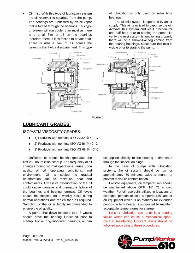
Ring oil lubricated: This system utilizes
slinger rings running in, or near the bearings to pick oil up from the bearing housing oil reservoir and deposit it on the shaft. The oil then is transferred to the bearings by means of channeling and/or catch-drip type devices. If it is required, heat exchangers or fans can be added to these type units to maintain acceptable lube oil temperatures. See Figures 4 & 5.
Units equipped with constant level oilers are adjusted at the factory to the proper level prior to shipment. However, the level should be checked prior to operation. The oil
level mark is either cast into the housing, or marked on an oil level tag which is attached to the housing. If the tag is missing, refer to factory supplied documentation. This oil level dimension is from the shaft centerline to the level of the oil in the bearing housing, which also correlates to the top of the star nuts. If it is necessary to adjust the star nuts, loosen and adjust to the proper height, and secure the bottom jam nut. Fill the bearing housing reservoirs to the required oil level. Fill oil bottle and position them on the star nuts and secure with thumb screws.
Page 18 of 29 Model: PWM & PWM-D Rev. C_8/21/2015
Oil mist: With this type of lubrication system the oil reservoir is separate from the pump. The bearings are lubricated by an oil vapor that is forced through the bearings. This type of system will run cooler than most as there is a small film of oil on the bearings therefore there is less friction to create heat. There is also a flow of air across the bearings that helps dissipate heat. This type
of lubrication is only used on roller type bearings.
The oil mist system is operated by an air supply. This air is utilized to vaporize the oil. Activate this system and let if function for one half hour prior to starting the pump. To verify the mist system is functioning properly there will be a smoke-like fog coming from the bearing housings. Make sure this mist is visible prior to starting the pump.
. Figure 5
LUBRICANT GRADES: ISO/ASTM VISCOSITY GRADES:
1) Products with nominal ISO VG32 @ 40° C
2) Products with nominal ISO VG46 @ 40° C
3) Products with nominal ISO VG 68 @ 40° C
Unfiltered oil should be changed after the first 250 hours initial startup. The frequency of oil changes during normal operations varies upon quality of oil, operating conditions, and environment. Oil is subject to gradual deterioration due to moisture, heat and contaminates. Excessive deterioration of the oil could cause damage and premature failure of the bearings and bearing journals. Oil levels should be checked on a weekly basis during normal operations and replenished as required. Sampling of the oil is highly recommended to ensure the oil quality.
A pump shut down for more than 3 weeks should have the bearing lubricated prior to startup. For oil ring lubricated bearings, oil can
be applied directly to the bearing and/or shaft through the inspection plugs.
In the case of pumps with lubrication systems, the oil system should be run for approximately 30 minutes twice a month to prevent moisture contamination.
For idle equipment, oil temperatures should be maintained above 60°F (16° C) in cold weather. For oil reservoirs utilized in locations of extended periods of cold temperatures, and/or on equipment which is on standby for extended periods, a tank heater is suggested to maintain acceptable temperatures for startup.
Loss of lubrication can result in a bearing failure which can cause a mechanical spark. Care in maintaining lubricant levels should be followed according to these procedures.

Page 19 of 29 Model: PWM & PWM-D Rev. B_8/21/2015
RECOMMENDED CONTROLS SETTINGS: ALARM SETTINGS FOR BEARING HOUSINGS:
Lube oil temperature settings (VG-32):
160°F (High oil sump temperature alarm)
185°F (High bearing temperature alarm)
195°F (High bearing temperature shut down setting)
Lube oil temperature settings (VG-46):
170°F (High oil sump temperature alarm)
185°F (High bearing temperature alarm)
195°F (High bearing temperature shut down setting
ALARM SETTINGS FOR CASE RTD:
25°F above product temperature (High temperature alarm)
35°F above product temperature (High temperature shut down setting)
VIBRATION SETTINGS:
0.20 In/Sec RMS (High vibration alarm)
0.45 In/Sec RMS (High vibration shut down setting)
It is the responsibility of the end user to utilize safety equipment to monitor the product. Temperature monitoring devices are available by customer request if not already purchased and installed.
PRE-STARTUP PROCEDURES 1) Verify that all piping has been properly
installed and tightened to the proper torque values on the flange bolting.
2) Verify that the shaft rotates freely. 3) Verify that the mechanical seals are set,
and that the set tabs have been removed.
4) Verify that the motor has been checked for proper rotation, and that the magnetic centering of the motor was taken into consideration for the installation of the coupling.
5) Verify that the unit has been properly aligned.
6) Check to ensure that bearing housings have been filled to the proper level of oil. Housings equipped with constant level oilers should have the oiler on the upside of the shaft rotation. See Figure 6.
7) Verify on oil slinger ring fitted pumps, that the rings are free and not bound inside the housing. This can be done by removing the inspection plugs and rotating the element enough to verify free ring movement.
8) Units equipped with auxiliary oil systems should be checked for proper oil fill levels. Units should be checked for proper operation and heat exchanger motor rotation.
9) Pre-lubricate bearing prior to startup. For ring lubricated housings, pull inspection plugs and pour a small
amount of oil through the oil ring inspection holes in the sleeve bearings, and in the end cover trough at the thrust bearing. Auxiliary oil systems should be
started approximately 30 minutes prior to startup. Verify oil circulation through housings. Sight flow indicators should be provided in the oil return line. Ensure main oil pump is primed.
10) Hot service pumps, such as boiler feed water, should be pre-heated prior to operation. Heating time should be not over 100°F per hour of temperature change until the case reaches within 100°F under the product temperature. The case should be allowed sufficient
Figure 6
Page 20 of 29 Model: PWM & PWM-D Rev. C_8/21/2015
time to normalize in temperature. As a rule of thumb, allow a minimum of 1 hour per inch of thickness at the thickest point of the case (normally the parting flange). If the components are heated too rapidly and/or the components are not given enough time to normalize in temperature, warpage due to uneven thermal expansion can cause the rotor to bind in the internal stationary rings. Starting in this condition could damage
the internal components. Heating is usually performed with a warm-up or bypass line. The suction valve is to be open as not to over pressure the case. Open the warm-up line to allow a small amount of hot fluid to circulate through the pump.
11) Ensure all guards are in place at the coupling and over seal glands, as applicable.
STARTUP PROCEDURES Pump should be vented at the high points of
the casing, suction and seals prior to operation. Failure to properly vent entrapped air can cause damage to the mechanical seals and pump internals.
With the discharge valve closed, slowly open the suction valve and allow product to enter the pump. Open vent valves to remove all air from the pump. Unit will be fully vented when fluid runs clear with no bubbles.
Once the pump is primed, If no bypass valve or line is used, set the discharge valve at 10% open. If a minimum flow bypass line or actuator valve is used for start-up purposes, the discharge valve may be closed. Ensure that valves on the minimum flow line are open.
Note: When the pump is located above suction source the discharge valve cannot be opened until the drive has been started since this would cause loss of prime.
Start the pump. As soon as it begins to develop pressure, start slowly opening the discharge valve. Avoid making any abrupt change in discharge velocity in order to prevent surging within the piping. Surging can cause serious damage to the internals of the pump.
The pump should reach discharge pressure as soon as it reaches operating speed. If does not happen, shut the pump down immediately. Re-vent and prime the pump and try re-starting.
START-UP INSPECTION Pull bearing housing inspection plugs and check the slinger rings at the bearings to insure that they are rotating and picking up oil. If any of them are not, shut the unit down immediately and investigate the cause of the problem.
1) For auxiliary oil systems, check oil flow through sight flow indicators in the drain lines.
2) Check for seal leakage. If a minor leak does not stop after a few minutes of operation, shut the unit down and re-set seal. Seal failure can cause a mechanical spark. Follow preventative maintenance schedule.
3) Check for leaks in all the piping, vents and drains, suction and discharge, lube oil, etc.
4) Monitor bearing housing and oil temperatures to ensure proper bearing and oil temperatures. Shut down if there is a sudden temperature rise, or if temperatures continue to rise past the desired operating range.
5) Monitor oil levels and ensure that there is no leakage at the bearing isolators.
6) On auxiliary oil systems, observe during startup to ensure auxiliary pump to main pump cutover. Monitor oil pressures to ensure constant and within the proper operating parameters.
7) Monitor differential pressures across the filters on auxiliary oil systems. Change filters as necessary.
8) Monitor differential pressure across the suction strainer. Shutdown and clean as necessary if there is an increase of 5 psig or more.
9) Monitor vibration readings, especially those attributed to misalignment. A hot alignment may be necessary to adjust for thermal growths.
10) Monitor vibration readings, especially those attributed to misalignment. A hot alignment may be necessary to adjust for thermal growths.

Page 21 of 29 Model: PWM & PWM-D Rev. C_8/21/2015
SHUTDOWN 1) De-energize driver. If the driver unit is a
turbine, trip the manual over speed trip device.
2) Monitor coast down to ensure no that the unit does not stop abruptly. If this occurs, under no circumstance should excessive force be applied to turn the element, as this could possibly cause severe damage to the internal components. The rotating element should be pulled from the pump casing,
and the internal wear parts and rotor cleaned and checked for galling.
3) Lose discharge valve and bypass line, prior to closing suction valve.
4) Close suction valve last. 5) In cold weather, units with product
susceptible to freezing should be drained, if unit is to sit idle for an extended period (sufficient time for the possibility of freezing).
EXTENDED SHUTDOWN A shut down for more than one month
should be manually lubricated on oil slinger ring equipped pumps. Bearing housing oil should be sampled and changed as required.
On units equipped with auxiliary oil lube systems, the lube system should be run twice a month for approximately 30 minutes.
For pumps with product susceptible to freezing, fluid should be drained from casing and heat exchangers, if so equipped.
MAINTENANCE
PREVENTATIVE MAINTENANCEIn order to keep your new equipment
running at peak and trouble free performance, a preventative and predictive maintenance program should be established and maintained. The schedule listed below is suggested only as a minimum. The preventative maintenance program you establish should be based on the equipment’s usage, service, and history.
As an indicator of the pump’s performance and overall health, the end user should use the following:
Performance Monitoring Vibration Monitoring Temperature Monitoring Oil Analysis A baseline of performance should be
established and periodically monitored for losses in efficiency and performance. This will be a good indicator of the wear to the internal components. It is up to the end user to evaluate the performance data and determine the best time to remove the pump for reconditioning.
The PWM and PWM-D models are high performance units and it is the view of PumpWorks 610 that the vibration levels shall be constantly monitored, at minimum, on the outboard bearing housing horizontal position. Vibration is an early indicator of problems, either with the bearings, or within the pump itself.
It is also PumpWorks 610 view, that the bearing and product temperatures be constantly monitored. This also, is another pre-indicator of failure.
By monitoring the unit vibration and temperatures, a catastrophic failure of the unit can be avoided. So it is the responsibility of the end user to provide this equipment, if they do not decide to purchase them at the time of the unit order. Standard provisions on the bearing housings are provided for RTDs and vibration monitors.
Oil analysis is also a good indicator of the health of the sleeve or ball bearings. And it is highly advised that the end user utilizes this technology.

Page 22 of 29 Model: PWM & PWM-D Rev. C_8/21/2015
Preventative Maintenance Description Frequency
Initial Startup & Commissioning Oil System Change Lube Oil 1st 250 hours
Suction Strainer Check pressure differential across suction strainer Every 2 Hours for 1st Day
Mechanical Seal Visually inspect 1st Hour After Startup
Auxiliary Piping Visually inspect 1st Hour After Startup
Instrumentation Check instruments for proper function and verify calibration readings.
1st Hour After Startup
Unit Monitoring Monitor bearing temperature rise and stabilization. Ensure no sudden temperature rises. Check vibration readings for abnormalities.
1st 8 Hours After Startup
Normal Operations Oil System Change Lube Oil (Continuous Operation) Every 2000 hours Oil System Change Lube Oil (Standby Operation) Every 6 Months
Lube Oil Filters Check pressure differential across filter. Daily Suction Strainer Check pressure differential across suction strainer Daily Unit Monitoring Monitor vibration, bearing and case temperatures Daily
Mechanical Seal Monitor for leaks Daily Auxiliary Piping Visually inspect Monthly
Cleanliness Check for oil leakage and dust buildup Monthly Performance Check pump performance & efficiency Every 6 Months
Table 1 MECHANICAL SEAL / BEARING HOUSING REMOVAL
Packages manufactured by PumpWorks610 are made for replacement of the mechanical seals, without disturbing the pump or driver. For this purpose, packages are supplied by PumpWorks610, and in compliance with API 610 specifications, with a spacer coupling to allow clearance for seal removal
The following procedures are given as a customer reference only, and do not necessarily cover every step of removal for every configuration of construction. It is the end users responsibility to ensure that care is taken not to
damage components, fits, and finishes which could cause leakage of the product, possible failure of bearings, or of the entire unit. Maintenance should be performed by experienced and qualified personnel, and should be performed in compliance with all safety regulations and procedures.
PumpWorks610 maintenance personnel are available for service, supervision, training, or consultation. Anytime bearing housing is disturbed replace ball bearings. Removal instructions are as follows:
BALL / BALL BEARING HOUSING (INBOARD)
1) Follow all Lockout/Tag Out Procedures prior to removal of guards and maintenance of unit.
Ensure ALL electrical sources have be de-energized and locked out.
Ensure suction, discharge, and bypass valves have been closed and secured.
Drain fluids from pump and bearing housing that is to be removed. Use proper precautions for hazardous or flammable liquids. Remove constant
oiler globes. Refer to applicable MSDS sheets as necessary.
2) Remove coupling guard. 3) Remove RTD probes, as applicable. 4) Remove pump coupling hub. Normal
standard shaft extensions have a 1 1/4” taper per foot on diameter taper. Loosen the set screw in the nut face. Back the coupling nut off a few rounds. A puller may be used to put pressure on the coupling hub, and with a soft or brass hammer, a mild bump on the back shoulder should disengage the

Page 23 of 29 Model: PWM & PWM-D Rev. C_8/21/2015
taper fit. Be careful not to damage back fit on gear shroud couplings.
5) Remove fan shroud and fan as applicable. 6) Remove outboard cover. 7) The oil slinger ring is accessible once the
cover is removed. Remove oil ring through the outboard cover register bore. Inspect oil ring to ensure round and no damage. Replace as necessary.
8) Remove bolting on the inboard cover. 9) The housing can now be pulled off of the
bearings. 10) Bent “W” washer lock tab out of slot in the
bearing retaining nut. The bearing nut, lock washer, oil ring carrier, and bearing can now be removed.
11) Remove inboard cover. 12) The seal is now accessible. Remove and
replace per seal manufacturer’s instructions. 13) After installation of seal, reverse order of
assembly per above. Seal should be set after reinstallation of the housing and bearings. Manually oil bearings prior to rotation. New bearing retaining nuts and “W” lock washers should always be used during re-installation.
14) Ensure all guards are installed prior to operation.
15) After re-pressurization of the casing and during startup of the unit, monitor seals for leaks and take corrective actions if leaks occur.
BALL / BALL BEARING HOUSING (OUTBOARD)
1) Follow all Lockout/Tag Out Procedures prior to removal of guards and maintenance of unit. Ensure ALL electrical sources have
be de-energized and locked out. Ensure suction, discharge, and
bypass valves have been closed and secured.
Drain fluids from pump and bearing housing that is to be removed. Use proper precautions for hazardous or flammable liquids. Remove constant oiler globes. Refer to applicable MSDS sheets as necessary.
2) Remove coupling guard, as necessary for rotating shaft.
3) Remove RTD probes, as applicable. 4) Remove fan shroud and fan as
applicable. 5) Remove outboard cover. 6) The oil slinger ring is accessible once
the cover is removed. Remove oil ring through the outboard cover register bore. Inspect oil ring to ensure round and no damage. Replace as necessary.
7) Remove bolting on the inboard cover. 8) The housing can now be pulled off of
the bearings.
9) Bent “W” washer lock tab out of slot in the bearing retaining nut. The bearing nut, lock washer, oil ring carrier, bearings and shim can now be removed. Do not loose shim between the thrust bearing and shaft shoulder! This shim is used to center the rotating assembly to the internal components. Failure to re-install this shim could result in severe damage.
10) Remove inboard cover. 11) The seal is now accessible. Remove
and replace per seal manufacturer’s instructions.
12) After installation of seal, reverse order of assembly per above. Seal should be set after reinstallation of the housing and bearings. Manually oil bearings prior to rotation. New bearing retaining nuts and “W” lock washers should always be used during re-installation.
13) Ensure all guards are installed prior to operation.
14) After re-pressurization of the casing and during startup of the unit, monitor seals for leaks and take corrective actions if leaks occur.
SLEEVE BEARING HOUSING (INBOARD)
1) Follow all Lockout/Tag Out Procedures prior to removal of guards and maintenance of unit. Ensure ALL electrical sources have
be de-energized and locked out. Ensure suction, discharge, and
bypass valves have been closed and secured.
Drain fluids from pump and bearing housing that is to be removed. Use proper precautions for hazardous or flammable liquids. Remove constant oiler globes. Refer to applicable MSDS sheets as necessary.
2) Remove coupling guard.

Page 24 of 29 Model: PWM & PWM-D Rev. C_8/21/2015
3) Remove RTD probes, as these protrude into the bottom half of the bearing shell.
4) Disconnect and remove proximity probes and vibration monitors as necessary, or applicable.
5) Remove pump coupling hub. Normal standard shaft extensions have a 1 1/4” taper per foot on diameter taper. Loosen the set screw in the nut face. Back the coupling nut off a few rounds. A puller may be used to put pressure on the coupling hub, and with a soft or brass hammer, a mild bump on the back shoulder should disengage the taper fit. Be careful not to damage back fit on gear shroud couplings.
6) Remove bearing housing top half. 7) Disconnect drain and inlet lines as
applicable. 8) Remove screws in sleeve bearing top.
Pull top half of the bearing off. By lifting up on the shaft, the lower half of the bearing can be rolled out. Be extremely
careful not to damage sleeve bearing journal, as this will adversely affect the bearing life, and could result in damage to pump internals.
9) Remove lower bottom half bearing housing.
10) Remove the bearing isolator and oil rings from the shaft. The seal is now accessible. Remove and replace per seal manufacturer’s instructions. Inspect oil rings to ensure round and no damage. Replace as necessary.
11) After installation of seal, reverse order of assembly per above. Seal should be set after reinstallation of the housing and bearing. Manually oil bearings prior to rotation.
12) Ensure all guards are installed prior to operation.
13) After re-pressurization of the casing and during startup of the unit, monitor seals for leaks and take corrective actions if leaks occur.
SLEEVE – BALL THRUST BEARING HOUSING (OUTBOARD)
1) Follow all Lockout/Tag Out Procedures prior to removal of guards and maintenance of unit. Ensure ALL electrical sources have
be de-energized and locked out. Ensure suction, discharge, and
bypass valves have been closed and secured.
Drain fluids from pump and bearing housing that is to be removed. Use proper precautions for hazardous or flammable liquids. Remove constant oiler globes. Refer to applicable MSDS sheets as necessary.
2) Remove coupling guard, as necessary for rotating shaft.
3) Remove RTD probes, as these protrude into the bottom half of the bearing shell.
4) Disconnect and remove proximity probes and vibration monitors as necessary, or applicable.
5) Remove bearing housing top half. 6) Disconnect drain and inlet lines as
applicable. 7) Pull outboard bearing cover. 8) Remove screws in sleeve bearing top.
Pull top half of the bearing off. By lifting up on the shaft, the lower half of the bearing can be rolled out. Be extremely careful not to damage sleeve bearing journal, as this will adversely affect the
bearing life, and could result in damage to pump internals.
9) Back off set screws as necessary on thrust bearing nut. Remove nut and bearing retaining band. Bearing nuts come off the direction the unit turns. Pull thrust bearing. Thrust bearing should be replaced new – especially if shaft is an interference fit to the inner bearing race. Do not loose shim between the bearing and shaft shoulder! This shim is used to center the rotating assembly to the internal components. Failure to re-install this shim could result in severe damage.
10) Remove lower bottom half bearing housing.
11) Remove the bearing isolator and oil rings from the shaft. The seal is now accessible. Remove and replace per seal manufacturer’s instructions. Inspect oil rings to ensure round and no damage. Replace as necessary.
12) After installation of seal, reverse order of assembly per above. Seal should be set after reinstallation of the housing and bearing. Manually oil bearings prior to rotation.
13) Ensure all guards are installed prior to operation.
14) After re-pressurization of the casing and during startup of the unit, monitor seals for leaks and take corrective actions if leaks occur.
Page 25 of 29 Model: PWM & PWM-D Rev. B_8/21/2015
SLEEVE – TILTING PAD BEARING HOUSING (OUTBOARD)
1) Follow all Lockout/Tag Out Procedures prior to removal of guards and maintenance of unit. Ensure ALL electrical sources have
be de-energized and locked out. Ensure suction, discharge, and
bypass valves have been closed and secured.
Drain fluids from pump and bearing housing that is to be removed. Use proper precautions for hazardous or flammable liquids. Remove constant oiler globes. Refer to applicable MSDS sheets as necessary.
2) Remove coupling guard, as necessary for rotating shaft.
3) Remove RTD probes, as these protrude into the bottom half of the bearing shell.
4) Disconnect and remove proximity probes and vibration monitors as necessary, or applicable.
5) Pull outboard bearing cover and main oil pump. Check oil pump to ensure that it turns freely and smoothly. Disassemble and inspect if unit feels rough.
6) Remove bearing housing top half. 7) Disconnect drain and inlet lines as
applicable. 8) Remove screws in sleeve bearing top.
Pull top half of the bearing off. By lifting up on the shaft, the lower half of the bearing can be rolled out. Be extremely careful not to damage sleeve bearing journal, as this will adversely affect the bearing life, and could result in damage to pump internals.
9) Remove thrust bearing shoes and place where they are not subject to damage. Keep shoes in sets for inboard and outboard positions. Inspect and replace as necessary.
10) Back off set screws as necessary in thrust bearing nut. Remove thrust bearing retaining nut. Thrust bearing nuts come off the direction the unit turns. Pull thrust disc. Do not loose shim between the thrust disc and shaft shoulder! This shim is used to center the rotating assembly to the internal components. Failure to re-install this shim could result in severe damage.
11) Remove lower bottom half bearing housing.
12) Remove the bearing isolator, chamber ring, and oil rings from the shaft. The seal is now accessible. Remove and replace per seal manufacturer’s instructions. Inspect oil rings to ensure round and no damage. Replace as necessary.
13) After installation of seal, reverse order of assembly per above. Seal should be set after reinstallation of the housing and bearings. Manually oil bearings prior to rotation.
14) Ensure all guards are installed prior to operation.
15) After re-pressurization of the casing and during startup of the unit, monitor seals for leaks and take corrective actions if leaks occur.
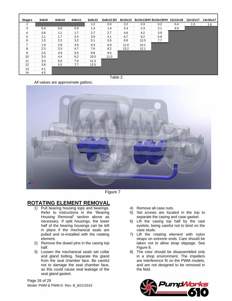
REMAINING UN-DRAINED PRODUCT After draining the pump, some product will
be trapped in the short crossovers and balance lines, in cases where the balance lines are located on the bottom of the casing as in Figure 7. On casings with the balance lines located on the side, the balance lines are fully drained upon draining of the suction neck. Also note areas of the inter-stage short crossovers where liquid will be trapped. These areas are located in blue in the illustration.
The following volumes in Table 2 are estimated, with the assumption that the long cross under, suction and discharge necks are
fully drained. Where no drain connections are provided in the suction and discharge neck, it is assumed that drains are provided in the suction and discharge piping. Proper safety precautions should be taken against exposure to product.
If the unit is to be transported, precautions should be taken, when necessary, to contain fluids that may be released during shipment.
During the removal of the element, a small volume of un-drained fluid will be released. Proper precautions should be made to prevent spillage and / or exposure.
Page 26 of 29 Model: PWM & PWM-D Rev. B_8/21/2015
Stages 3x6x9 4x6x10 4x6x11 6x8x12 6x8x12.5H 8x10x13 8x10x13HH 8x10x15HH 12x12x16 12x12x17 14x16x172 1.2 0.0 2.2 0.3 0.2 0.4 1.3 1.63 0.4 0.6 0.9 1.4 1.4 2.4 2.3 2.1 4.94 0.8 1.1 1.7 2.7 2.7 4.6 4.2 3.95 1.1 1.7 2.4 3.9 4.1 6.7 6.2 5.86 1.5 2.2 3.2 5.1 5.5 8.9 12.0 7.77 1.9 2.8 3.9 6.3 6.9 11.0 10.18 2.3 3.3 4.7 7.6 8.2 13.2 12.19 2.6 3.9 5.5 8.8 9.610 3.0 4.4 6.2 10.0 11.011 3.4 5.0 7.0 11.312 3.8 5.5 7.7 12.513 4.114 4.5
Table 2 All values are approximate gallons.
Figure 7
ROTATING ELEMENT REMOVAL 1) Pull bearing housing tops and bearings.
Refer to instructions in the “Bearing Housing Removal” section above as necessary. If split housings, the lower half of the bearing housings can be left in place if the mechanical seals are pulled and re-installed with the rotating element.
2) Remove the dowel pins in the casing top half.
3) Loosen the mechanical seals set collar and gland bolting. Separate the gland from the seal chamber face. Be careful not to damage the seal chamber face, as this could cause seal leakage of the seal gland gasket.
4) Remove all case nuts. 5) Set screws are located in the top to
separate the casing and case gasket. 6) Lift the casing top half by the cast
eyelets, being careful not to bind on the case studs.
7) Lift the rotating element with nylon straps on extreme ends. Care should be taken not to allow strap slippage. See Figure 8.
8) The rotor should be disassembled only in a shop environment. The impellers are interference fit on the PWM models, and are not designed to be removed in the field.

Page 27 of 29 Model: PWM & PWM-D Rev. C_8/21/2015
9) The reinstallation of the rotor should be performed in reverse order of the above steps. The case ring locking pins should all be turned to the top for installation, and rolled into the locking slot once the element is landed in the casing. If this is a replacement element, the rotating element will need to be checked for centering in the stationary wear parts and volutes, and checked for TIR.
10) To set centering, use a magnetic base dial indicator on one end of the pump, and set the indicator parallel to the shaft axis. Using a screw driver or small pry
bar between an impeller and the shroud wall, carefully push the element all the way toward the dial indicator. Set the indicator to “0”. Carefully push the element in the opposite direction and record the total distance. Care should be taken not to damage the case split line or impeller when pushing the element. The centering setting should be half of the total travel of the indicator when the centering shim and thrust bearing are installed. Adjust centering shim thickness as necessary to set the proper centering.
Figure 8
Page 28 of 29 Model: PWM & PWM-D Rev. C_8/21/2015
Figure 8
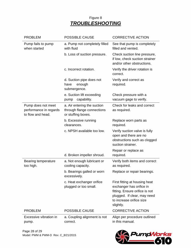
TROUBLESHOOTING
PROBLEM POSSIBLE CAUSE CORRECTIVE ACTION
Pump fails to pump when started
a. Pump not completely filled with fluid
See that pump is completely filled and vented.
b. Loss of suction pressure. Check suction line pressure, if low, check suction strainer and/or other obstructions.
c. Incorrect rotation. Verify the driver rotation is correct.
d. Suction pipe does not have enough submergence.
Verify and correct as required.
e. Suction lift exceeding pump capability.
Check pressure with a vacuum gage to verify.
Pump does not meet performance in regards to flow and head.
a. Air entering the suction through flange connections or stuffing boxes.
Check for leaks and correct as required.
b. Excessive running clearances.
Replace worn parts as required.
c. NPSH available too low. Verify suction valve is fully open and there are no obstructions such as clogged suction strainer.
d. Broken impeller shroud. Repair or replace as required.
Bearing temperature too high.
a. Not enough lubricant or cooling capacity.
Verify both items and correct as required.
b. Bearings galled or worn excessively.
Replace or repair bearings.
c. Heat exchanger orifice plugged or too small.
First fitting at housing heat exchanger has orifice in fitting. Ensure orifice is not plugged. If clear, may need to increase orifice size slightly.
PROBLEM POSSIBLE CAUSE CORRECTIVE ACTION
Excessive vibration in pump.
a. Coupling alignment is not correct.
Align per procedure outlined in this manual.

Page 29 of 29 Model: PWM & PWM-D Rev. C_8/21/2015
REVISIONS:
Rev A: Added PWM-D 5/24/11 Rev B: Reformatted and updated 9/8/15 Rev C: Updated Declaration of Conformity
b. Something lodged in an impeller.
Remove the case top half and remove foreign object or objects.
c. Broken impeller. Repair or replace as required.
d. Foundation or support structure not rigid enough.
If an obvious solution is not apparent consult the factory
e. Worn or damaged bearings.
Replace or repair as necessary.
f. Piping connected to the pump not properly supported.
Correct as required. Consult factory if in doubt.
Motor runs hot. a. Not enough NPSH causing the demand on the pump to be too high.
Consult the factory for re-rating information.
b. Viscosity change has been made thereby exceeding the motor rating.
Consult the factory for re-rating information.