bio-inspired band-gap tunable ...mkolle.scripts.mit.edu/.../2014/07/...materials.pdf · light...
TRANSCRIPT
www.advmat.dewww.MaterialsViews.com
CO
MM
UN
ICATIO
Bio-Inspired Band-Gap Tunable Elastic Optical Multilayer Fibers
Mathias Kolle , * Alfred Lethbridge , Moritz Kreysing , Jeremy J. Baumberg , Joanna Aizenberg , and Peter Vukusic *
N
Knowledge of the interplay between the morphology, compo-sition and optical appearance of biological photonic systems can provide broad inspiration for novel artifi cial photonic ele-ments. [ 1–3 ] On occasion, the study of natural photonics yields specifi c design templates for optical technologies. [ 4–9 ] To this end, we present the results of the investigation of the hierar-chical photonic structure discovered in the seed coat of Margar-itaria nobilis fruits, which directly inspired our creation of novel photonic fi bers. The fruit’s hue results from the interference of light within a concentrically-layered architecture found inside individual cells in the seed’s outer tissue layers. The natural structure presents two codependent, technologically exploitable features for light and color manipulation: regularity on the nano-scale that is superposed with microscale cylindrical symmetry, resulting in wavelength selective scattering of light in a wide range of directions. This is the foundation for novel soft bio-inspired photonic fi bers with the spectral fi ltering capabilities and color brilliance of a planar Bragg stack compounded with a large angular scattering range introduced by the microscale curvature, which also decreases the strong directional chroma-ticity variation usually associated with fl at multilayer refl ectors. Transparent and elastic synthetic materials equip the multilayer interference fi bers with high refl ectance that is dynamically tuned by longitudinal mechanical strain. A two-fold elongation of the elastic fi bers results in a shift of refl ection peak center wavelength of over 200 nm. The bio-inspired design and manu-facture of this form of soft photonic fi ber heralds the transi-tion to novel fi ber-based fl exible photonic materials and textiles
© 2013 WILEY-VCH Verlag Gm
Dr. M. Kolle, Prof. J. AizenbergHarvard University School of Engineering and Applied Sciences 9 Oxford Street, Cambridge, MA-02138, USA E-mail: [email protected] A. Lethbridge, Prof. P. Vukusic, University of Exeter School of Physics Stocker Road, Exeter, EX4 4QL, UK E-mail: [email protected] Dr. M. KreysingL. Maximilians University Systems Biophysics Department of Physics Amalienstr. 54, München, D-80799, Germany Prof. J. J. BaumbergUniversity of Cambridge Nanophotonics Centre Cavendish Laboratory JJ Thompson Ave, Cambridge, CB3 0HE, UK
DOI: 10.1002/adma.201203529
Adv. Mater. 2013, 25, 2239–2245
with colors that are tunable over the entire visible spectrum and optical strain sensors.
Nature’s most vivid colors, highest transparencies, strongest whites and deepest blacks rely on ordered, quasi-ordered or dis-ordered structures with lattice constants or scattering element sizes on the order of the wavelength of visible radiation. [ 10–16 ] By inducing interference or diffraction, biological photonic structures of a wide structural diversity strongly alter the spec-tral composition of refl ected and transmitted light resulting in the stunning structural colors of many organisms. [ 17 , 18 ] One-dimensional multilayer arrangements play an important role in the creation of structural colors in nature and have prima-rily been studied in the animal kingdom, especially the insect world. [ 10 , 19 , 20 ] Planar layered photonic system have recently also been increasingly frequently reported in various plants. [ 21–24 ]
The fruits of the plant Margaritaria nobilis in the rain forests of Middle and South America have a striking blue - green hue ( Figure 1 a). The plant partly relies on seed dispersal by birds which might be attracted by the colorful display. [ 25 , 26 ] The cells in the fruit’s blue seed coat are elongated and mostly appear blue or green (Figure 1 a,b). Several layers of cells are stacked on top of each other with varying planar orientation of the individual cell layers (Figure 1 c). A single cell cross-section reveals that the entire interior volume is occupied by a periodic concentrically-layered morphology with an overall periodicity of (180 ± 30) nm (Figure 1 d, e). Light incident on the fruit’s surface undergoes interference within the periodic structure in each cell resulting in the refl ection of blue light.
Under directional illumination a planar multilayer inter-ference structure can only display its bright coloration in the specular refl ection direction. The hue of such planar Bragg stacks strongly depends on the angle of incidence. Under dif-fuse illumination the observed color blue-shifts for increasing observation angle. By contrast, in M. nobilis fruits the superpo-sition of a microscopic curvature on the nanoscale regularity of the layered structure within each individual seed coat tissue cell combined with the fruit’s overall macroscopic curvature leads to an increased visibility of the refl ected structural color across a wide angular range. Under directional illumination, a part of the curved multilayer in a majority of the individual cells is oriented to satisfy the specular refl ection condition providing a spatially varying pixelated sparkle of different hues (Figure 1 a) that depend on the locally varying angle of light incidence. In diffuse light this sparkle is suppressed as the light refl ected by each fruit cell towards the observer originates from light inci-dent on the fruit from various directions, producing a more iso-tropic color that only gradually changes across the fruit due to the macroscopic curvature.
bH & Co. KGaA, Weinheim 2239wileyonlinelibrary.com

2240
www.advmat.dewww.MaterialsViews.com
CO
MM
UN
ICATI
ON
Figure 1 . Fruit and fi bers. (a) A Margaritaria nobilis fruit without its capsule ( ∼ 10 mm in diameter). (b) Optical micrograph of the fruit’s surface showing the elongated blue cells. (c) A scanning electron micrograph of a cross-section through the outer layers of the fruit’s endocarp is showing several stacks of cells. (d) A cross-section through a single tissue cell reveals the interior architecture - a concentric, fl attened cylindrical layered structure. (e) A sec-tion of the layered architecture within a single cell visualized by transmission electron microscopy. (f) Schematic representation of the manufacturing of artifi cial photonic fi bers. (g) Optical micrographs of three rolled-up multilayer fi bers with different layer thicknesses and colors in refl ection (top) and transmission (bottom). (h) Scanning electron micrograph of a fi ber cross-section showing the multilayer cladding wrapped around the fi ber’s glass core. (i) Scanning electron micrograph of the individual layers in the cladding. Scale bars: 200 μ m (b), 20 μ m (c), 10 μ m (d), 500 nm (e), 20 μ m (g), 20 μ m (h) and 1 μ m (i).
The emergence of unique structural and optical properties from combinations of structures on different length scales within hierarchical synergistic assemblies is a principle often encountered when studying natural systems. [ 19 , 27 ] Increasingly frequently this concept is also applied in novel optical technolo-gies. [ 6 , 7 , 9 ] The hierarchical photonic architecture in the seed coat of the M. nobilis fruit is the key element involved in the crea-tion of intense blue and green hues. It provides inspiration for the manufacture of artifi cial photonic fi bers with the optical functionality being defi ned by the interplay of nanoscopic regu-larity and superimposed microscopic curvature. The artifi cial bio-inspired system presented in this article consists of concen-tric multilayer-wrapped fi bers with a radially periodic refractive index profi le built from only two alternating phases. While sim-ilar to its natural model in dimensions and underlying optical interactions, the artifi cial system avoids many of the complexi-ties in the natural structure including the ellipticity of the fruit cells’ cross-section and any existing fi ne structure within the periodic layers.
Optical fi ber systems with multilayer claddings have theo-retically been discussed since the late 70’s and have more recently been manufactured using standard fi ber drawing proc-esses from macroscopic preforms. [ 28–32 ] The choice of mate-rials that can be drawn into multilayer fi bers is constrained to a limited, albeit continuously expanding set of components. [ 33 ] In particular, the preform material combinations need to pro-vide an appropriate refractive index contrast and have matching thermal expansion coeffi cients in order to prevent fracturing at the material interfaces during the processing at elevated temperature. [ 33 ]
Here, we present an alternative approach that allows fabri-cation of fi bers at room temperature from a wide range of soft organic and also inorganic materials with varying optical and
wileyonlinelibrary.com © 2013 WILEY-VCH Verlag G
mechanical properties that are not restricted to a translational symmetry along the fi ber axis as in thermally drawn fi bers. The fi bers reported in this article consist of two elastomeric dielec-trics, polydimethylsiloxane (PDMS) and polyisoprene-polystyrene triblock copolymer (PSPI), two inexpensive materials that are commercially available in industrial quantities and provide a suffi ciently high refractive index contrast ( n PDMS = 1.41 ± 0.02, n PSPI = 1.54 ± 0.02, determined by ellipsometry). Multilayer fi bers are produced by initially forming a bilayer of the two constituent materials, which is subsequently rolled up onto a thin glass fi ber ( ≈ 10–20 μ m diameter) to form the multilayer cladding (Figure 1 f and Figure S1 in the Supporting Information). [ 34 , 35 ]
This material system, which was reported earlier in the con-text of planar fl exible multilayer systems, [ 34 ] was chosen here for its advantageous set of properties for the controlled tuning of the fi ber’s optical performance, which is demonstrated below. The fi ber rolling technique used to produce the fi bers has previ-ously been employed for the creation of multilayer claddings on rods with macroscopic diameter to facilitate the manufacture of microscopically planar multilayer stacks. Here, we show for the fi rst time that this technique can be employed to form concen-tric multilayers on core fi bers of only ∼ 15 μ m diameter using elastic materials. Such multilayer fi bers with curvature on the microscale display optical properties that are distinctly different from the macroscopic rolls previously produced. [ 35 ]
Other dielectric materials that have been used in the fi ber manufacture include thermoplastics, for instance polystyrene and poly(methyl methacrylate). Thin metal fi lms have been incorporated in non-stretchable fi bers with macroscale diam-eter employing the rolling technique. [ 35 ] Spray coating or blade coating, two industrially well-established techniques that are compatible with roll-to-roll processing, could be explored as viable alternatives for the bilayer production on a larger scale.
mbH & Co. KGaA, Weinheim Adv. Mater. 2013, 25, 2239–2245
www.advmat.dewww.MaterialsViews.com
CO
MM
UN
ICATIO
N
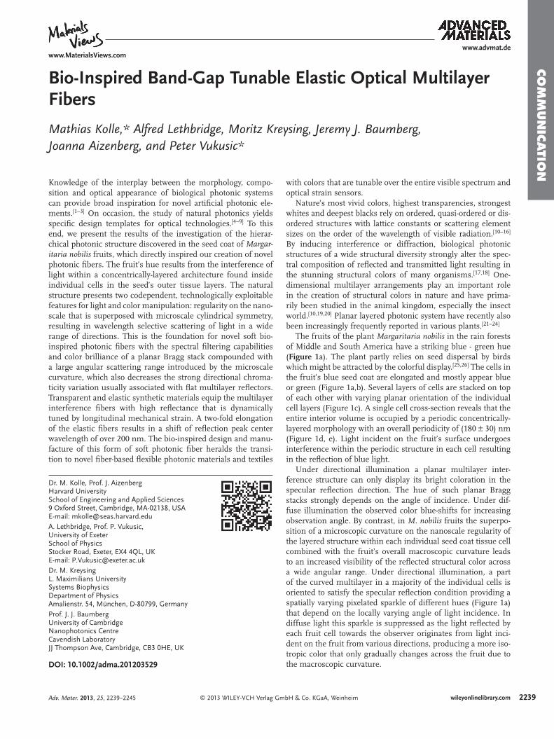
Figure 2 . Optical characterization of the fruit and the fi bers. (a) Optical micrograph of a fruit’s surface visualizing parts of elongated tissue cells. (b) The corresponding refl ection spectrum averaged along the red dashed line in (a). (c) Spectrally resolved intensity distribution acquired from a line scan (white dashed line in (a)) radially across a single cell showing the variation of the refl ection band induced by the curvature of the layered nanoscale architecture. E ph - photon energy, x - spatial position radially along the fi ber, centered at the fi ber axis. (d) Optical micrograph of a blue fi ber in refl ection. (e) The corresponding refl ection spectrum aver-aged along the red dashed line in (c). (f) Optical image of the same fi ber in transmission. (g) The corresponding transmission spectrum averaged along the red dashed line in (e). All scale bars: 20 μ m.
The individual thicknesses of the two fi lms in the initial bilayer can be tuned during the fi lm deposition. Consequently, the spectral position of the refl ection band of the fi bers can be freely adjusted. Three fi bers with high refl ectivity in different color ranges and the corresponding complementary color in transmission are shown in Figure 1 g. Scanning electron micro-graph images of the cross-section of a green fi ber visualize the concentric multilayer cladding with 80 periods wrapped around the core glass fi ber (Figure 1 h, i).
Similar to the optical signature of the tropical fruit ( Figure 2 a,b), these fi bers show a pronounced refl ection in a fi nite wave-length range imposed by the multilayer periodicity (Figure 2 d,e) and a corresponding drop in transmission (Figure 2 f,g). Fibers rolled with multilayer claddings of up to 150 periods provide a refl ectivity of more than 90% in their refl ection band and a bandwidth varying from 70 nm to 30 nm, decreasing with increasing number of layers in the cladding.
Collection of spectra along a line perpendicular to the fruit cell axis (white dashed line in Figure 2 a) allows for the recon-struction of the axially symmetric spatial refl ection intensity distribution (Figure 2 c). This measurement was also performed on the fi bers to determine their refl ection and transmission intensity distribution. Note that due to its curvature, the concen-tric multilayer refl ector translates the lateral distance from the fi ber’s symmetry axis at which each spectrum was taken into a corresponding incident angle ( Figure 3 a, b). This allows for the direct measurement of the dispersion relation of the multi-layer fi ber system in refl ection and transmission (Figure 3 c,d, for details see Figure S2 and discussion in the Supporting Information).
Under directional illumination the difference in radial varia-tion of the peak wavelength from fi ber and individual fruit cells results from a subtle difference in geometry. Cross-sections of the fruit cells show that the multilayer is arranged in concentric ellipses aligned with the major axis in the plane of the fruit’s surface which leads to a less pronounced color variation across a single cell. In contrast, the multilayer cladding of the artifi cial fi bers has a circular concentric cross-section inducing a radial color variation with larger gradient.
Finite difference time domain (FDTD) simulations of the fi bers’ optical performance were carried out on a high perform-ance computing cluster using the MIT electromagnetic equa-tion propagation software package (MEEP) [ 36 ] to explain the complexity of the measured dispersion diagrams and to predict the change in optical properties due to a variation in the fi ber design. This approach was motivated by the recent investiga-tion of a photonic structure in a fi sh retina, where FDTD simu-lations of the interaction of light with the complex hierarchical biological photonic system could provide valuable insight into the interplay of all components on the different length scales. [ 37 ] The simulations presented here result from interactions of light with a fi ber of 60 layers with 340 nm periodicity in the outer multilayer cladding zone matching the geometry of the blue fi ber from which the experimental dispersion diagrams were obtained. The inner cladding zone adjacent to the fi ber core was occupied by a small number of bilayers of ≈ 710 nm periodicity also found in the real fi ber. In the simulations the spatiotemporal electromagnetic fi eld amplitude distributions of light refl ected and transmitted by the fi ber are collected in
© 2013 WILEY-VCH Verlag GAdv. Mater. 2013, 25, 2239–2245
the fi ber’s near-fi eld after excitation with a broadband pulse. An appropriate far-fi eld transformation yields the refl ected intensities as a function of frequency or photon energy and wave vector component k x - i.e. the dispersion relation of the multilayer fi bres. [ 38 , 39 ] The band structures obtained in these simulations (Figure 3 f, g) match the experimentally acquired dispersion diagrams of the fi bers (Figure 3 c,d). The main Bragg refl ection peak at a photon energy of 2.5 eV (corresponding to a
2241wileyonlinelibrary.commbH & Co. KGaA, Weinheim

224
www.advmat.dewww.MaterialsViews.com
CO
MM
UN
ICATI
ON
Figure 3 . Comparison of optical modeling with experimental data. (a) Simplifi ed schematic representation of light refl ection from the fi ber into the vertical direction, revealing the relation between projected radial distance x from the multilayer fi ber symmetry axis and the angle of light incidence θ R (effects induced by the fi nite numerical aperture of illumination and collection optics, including extended light cones have been neglected in this sketch). (b) A similar schematic for light transversely transmitted by the fi ber. (c) Band diagram of the fi ber refl ection for light in the visible range. (d) Band diagram of the fi ber transmission. (e) The left image visualizes the FDTD simulation cell set-up used for optical modeling, including the cross-section of the fi ber with an inner cladding periodicity of 710 nm (yellow) and an outer periodicity of 340 nm (light blue), the incident light pulse spanning the whole visible range (red and blue), the refl ection and transmission detectors (green dashed lines) and absorbing boundaries at the cell edges (black). The following two images show the light pulse propagating transversely through the multilayer fi ber at two later points in time and for clarity, the fi ber is shown in its contours. In all three images the logarithm of the light pulse’s fi eld amplitudes is shown increasing in value from blue to red. (f, g) Refl ection and transmission band diagrams deduced from the simulations for perpendicular light incidence ( k x = 0 m − 1 ).
wavelength of 496 nm) and its spectral variation with propaga-tion direction is captured in both sets of data for transmission and refl ection. A blue-shift of the refl ection band is observed with increasing propagation angle in experiment and simula-tion. However, this spectral variation amounts to less than 40% of the blue-shift expected from a comparable fl at multilayer structure, showing that the curvature of the multilayer cladding more than halves the angular variation in chromaticity usually associated with multilayer refl ectors. The same effect arises for refl ection of light from the multilayered cells in the seed coat of the M. nobilis fruit (Figure 3 c) explaining its isotropic coloration in diffuse illumination.
In this particular fi ber sample, the splitting in the refl ec-tion band observed in experiment and simulation is caused by interference of light in the inner zone of the multilayer clad-ding with ≈ 710 nm periodicity surrounding the fi ber core. High frequency intensity fl uctuations as a function of photon energy in the simulations are caused by the fi ber core, which acts as a larger resonant cavity introducing an abundance of defect modes. This is not captured in the experimental data due to a limited spectral resolution. In fi ber designs with smaller cores these cavity modes would be detectable and potentially even be manifested in angle-dependent spectrally varying intensity fl uc-tuations visible to the naked eye. Some of the light propagating transversely through the fi ber experiences guiding within the individual layers resulting in additional weak modes seen at photon energies between 1.7–2.4 eV captured in simulations and experiments. These modes only occur for light polarized
2 wileyonlinelibrary.com © 2013 WILEY-VCH Verlag G
in the fi ber’s axial direction (see Figure S3 in the Supporting Information). A detailed investigation of this effect is beyond the scope of this paper and will be addressed elsewhere.
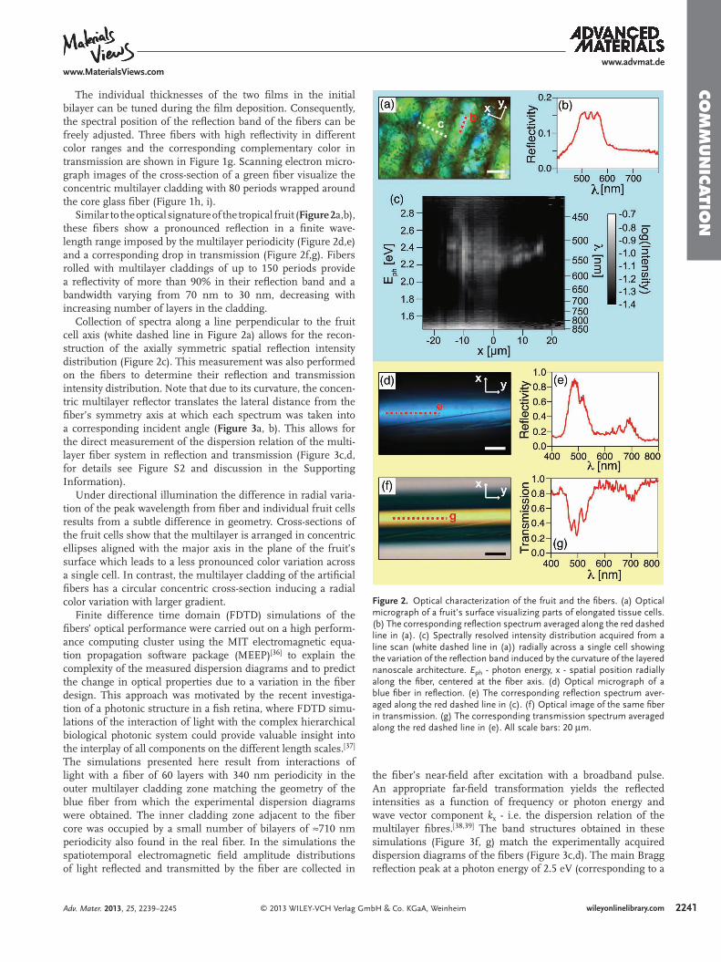
The glass fi ber that acts as the substrate for the multilayers in the rolling process can be removed from the fi ber by dis-solution in hydrofl uoric acid or by simply pulling it out of the multilayer cladding. Once the glass core is removed, the fi ber, being composed of two elastomers, can be elastically deformed by stretching it along its axis. An elongation along the fi ber axis leads to a compression perpendicular to it, causing a decrease of its overall diameter and a reduction of the thickness of each individual layer. Due to the comparable Poisson’s ratio of the constituent elastic materials the thickness ratio and the refl ec-tion intensity remain constant while the refl ection band blue-shifts. This way, the refl ected and transmitted color can be reversibly tuned by axial extension of the fi bers ( Figure 4 a,d). A reversible peak wavelength shift of over 200 nm has been recorded for axial elongations of a fi ber to over 200% of its orig-inal length (Figure 4 b,c).
From Poisson’s ratio and the proportionality between the thickness of individual layers in the cladding and the spectral band-gap position, the refl ection peak center wavelength λ peak is predicted to follow the relation λ peak = λ 0 peak (1 + ε ) − v , where λ 0 peak represents the refl ection peak centre wavelength at zero axial strain, ε the applied axial strain and v the fi bre’s Poisson’s ratio. Fitting the experimental data with this relation yields a Poisson’s ratio of v = 0.46 ± 0.02 for the stretchable multilayer fi bers matching the Poisson’s ratios of the constituent rubber
mbH & Co. KGaA, Weinheim Adv. Mater. 2013, 25, 2239–2245
www.advmat.dewww.MaterialsViews.com
© 2013 WILEY-VCH Verlag GmbH & Co. KGaA, Wein
CO
MM
UN
ICATIO
N
Figure 4 . Mechanical tuning of the fi bers’ optical performance: (a) Optical micrographs of a fully elastic fi ber showing the color tuning upon mechanical deformation induced by elonga-tion along the fi ber axis. The stiff glass core was removed from the fi ber by pullout. Scale bar 50 μ m. (b) The corresponding variation in the refl ection spectrum. The bottom spectrum is shown on absolute scale (this particular fi ber showed a peak refl ectivity of over 70%) and subsequent spectra are offset from the previous one by 0.15. The numbers correspond to the numbered micrographs in (a). (c) Variation of peak wavelength λ peak with applied strain ε . The open circles of different color correspond to three observed refl ection peaks (labeled in (b) with corresponding open circles). The lines represent fi ts based on a power law that results from considering the fi ber to be isotropically elastic, with the fi t parameter ν repre-senting the fi ber’s Poisson’s ratio. The error bars shown for a selection of data points cor-respond to the standard deviation of the peak positions obtained for fi ve consecutive stretch runs at different positions along the fi ber. (d) Color tuning of a second fi ber with different layer thickness where the glass core was removed by a hydrofl uoric acid etch. The fi ber color can be tuned throughout the whole visible spectrum. The dark spots on the fi ber result from scattering caused by etching artifacts found in at least the top PDMS fi lm in the multilayer cladding, which is also affected by the hydrofl uoric acid. Scale bar 50 μ m.
Adv. Mater. 2013, 25, 2239–2245
materials (Figure 4 c). This is in good agree-ment with results obtained earlier for the deformation of planar elastic multilayers. [ 34 ]
In this paper, we have given an example of the versatility of bio-inspired approaches for the manufacture of novel photonic elements. The hierarchical photonic architecture in individual cells of the fruits of the tropical plant Margaritaria nobilis served as a model for the creation of novel tunable band-gap multilayer fi bers with a large tuning range in the visible spectrum. Our room tempera-ture fi ber rolling technique allows fabrication of multilayer fi bers with hundreds of layers from a wide range of polymeric material com-binations that would not be realizable by con-ventional thermal fi ber drawing. The fi bers’ band-gap center frequency can initially be tuned by adjusting the individual fi lm thick-nesses of the two constituent layers prior to the rolling process, which also allows shifting of the fi bers’ tuning range into the near UV or near IR. Chirped multilayer fi bers can be realized by applying an appropriate force on the elastic bilayer during rolling of the multi-layer cladding (see Figure S1 in the supp. inf.).
The incorporation of gold or silver layers into the concentric multilayer offers poten-tial for the development of novel micron-scale fi ber-based meta-materials. Asymmetric structures or chirality could be incorporated into the fi bers by patterning of the ini-tial bilayer prior to the rolling, promising additional interesting optical properties. [ 40 ] Removal of the fi ber core from inside the multilayer cladding permits mechanical deformation of fi bers to more than twice their original length, which causes a tuning of the band-gap and a spectral blue-shift of over 200 nm. In the future, the incorporation of fl exible core fi bers will render the removal step obsolete. The fl exibility in the choice of constituent materials for the multilayer fi bers and their unique combination of mechanical and optical properties holds great potential for applications in mechanically tunable light guides or optical strain sensing. The fi bers’ mechanical fl exibility and elasticity, in addi-tion to the demonstrated color brilliance and tunability, can make them a versatile novel material for smart, color-dynamic textiles. The reported multilayer fi ber manufacturing process can in principle be applied to a wide range of synthetic materials with varying optical and mechanical properties. Large area deposition of the initial bilayer can be achieved by spraying or blade coating in a roll-to-roll process before fi nal rolling of the multilayer
2243wileyonlinelibrary.comheim

224
www.advmat.dewww.MaterialsViews.com
CO
MM
UN
ICATI
ON
fi bers. Hollow photonic fi bers providing good thermal insula-tion can be produced by employing hollow polymeric micro-tubing as the inner fi ber core. Exposure of the fi bers to different solvents in the vapor or liquid phase would result in varying degrees of swelling and a corresponding refl ection peak red-shift endowing the fi bers or textiles made thereof with optical solvent sensing capacities. The fi nal formation of the multilayer rolls could in principle also be achieved by self-induced rolling of the bilayer caused by directional stresses, which can be induced by gradually swelling one of the bilayer phases selectively. [ 41 ]
Experimental Section Fiber Manufacture : A thin polydimethylsiloxane (PDMS, Sylgard 184,
Dow Corning) fi lm was spun from a 4%wt solution in heptane onto a sacrifi cial water-soluble polystyrene-sulfonic acid layer on a silicon wafer. The PDMS fi lm was cross-linked by curing it on a hotplate for 2h at 70 ºC. Subsequently, a bilayer was formed by spin-coating a polystyrene-polyisoprene-polystyrene triblock copolymer (PSPI, Sigma Aldrich, 14%wt content polystyrene) fi lm on top of the cross-linked PDMS layer from a 4%wt solution in toluene (Figure 1 f left). Stripes of 12 cm by 1-2 cm of the bilayer were then released from the wafer onto the surface of a water bath. This was achieved by immersing the sample slowly into the water at an angle varying between 30–45º allowing the water to dissolve the sacrifi cial water-soluble fi lm between the elastomer bilayer and the substrate, thereby detaching the bilayer from the substrate. A thin glass fi ber (10-20 μ m diameter) was then lowered onto the end of the fl oating bilayer, where it adhered to the PSPI fi lm, the top layer in the bilayer. Once the core glass fi ber had attached it was rotated at a speed of 10–20 turns per minute rolling up the bilayer to form the multilayer cladding (Figure 1 f right). [ 34 , 35 ]
Structural and Optical Analysis : Images of the cross-sections of the fruit’s seed coat tissue cells were obtained by scanning electron microscopy (Hitachi S-3200N SEM). For imaging, the samples were coated with a 3 nm thick fi lm of a gold/palladium alloy. The cells internal periodic structure was visualized by transmission electron microscopy (JEOL 100S TEM). Images were acquired after fi xing and staining samples according to the protocol described elsewhere. [ 42 ] Cross-sections of the fi bers were obtained by cryo-fracture. Fractured fi bers were coated with a 3-5nm thick platinum fi lm to avoid charging artifacts during imaging and visualized using a fi eld emission scanning electron microscope (Zeiss Supra55VP).
Simultaneous imaging and micro-spectroscopic spatial refl ection/ transmission intensity mapping of the fruit’s surface and the fi bers was performed in a modifi ed optical microscope (Leica DMRX). The samples were illuminated in the area of interest with a halogen lamp in refl ection or transmission. Via an additional microscope port, a fraction of the refl ected light was collected confocally and guided by a fi ber to a spectrometer (Maya 2000 Pro, Ocean Optics). The detection spot size depends on the diameter of the fi ber and the magnifi cation of the objective lens. Measurements with a 50x objective (NA = 0.55) and a fi ber with 50 μ m core diameter resulted in a spatial resolution of 1 μ m. All spectra are referenced against a fl at silver mirror of ≥ 95% refl ectance in the wavelength range of 400–800 nm. In order to acquire spatially and spectrally resolved intensity distributions of a specifi c area on a sample, the sample was translated step-wise in the focal plane of the microscope with a minimum step size of 1 μ m using an automated, remote-controlled stage (Prior ES110). Individual spectra were acquired after each scanning step resulting in a complete map of the spectrally-resolved intensity distribution of the samples in refl ection or transmission.
Optical Modeling : The transverse refl ection and transmission of cylindrical multilayer fi bers was modeled using the MIT Electromagnetic Equation Propagation package (MEEP) [ 36 ] interfaced with custom-made C + + code to feed MEEP with the refractive index distributions in the simulation cell and to deduce the dispersion relations from the simulated fi eld distributions. The fi ber was modeled in cross-section
4 wileyonlinelibrary.com © 2013 WILEY-VCH Verlag G
with the layer thicknesses and the core fi ber diameter acquired from the scanning electron microscope images of fi ber cross-sections (d PDMS = 240 nm, d PSPI = 100 nm, d core = 14 μ m, Figure 1 h,i) and refractive indices of the constituent materials measured by ellipsometry (n PDMS = 1.41 n PSPI = 1.54, n core = 1.5). The modeling cell was bordered by absorbing boundaries simulating the effect of a fi nite numerical aperture of the microscope objective. A light pulse containing light of wavelengths 300–900 nm was propagated through the simulation cell. Detectors positioned above and below the fi ber captured the electromagnetic fi elds as a function of time and space. The distance of the detectors to the fi ber was chosen in order to detect waves propagating in an angular range that is commensurate with the numerical aperture of the microscope objective in the experiments. The detected fi elds served to deduce the refl ection and transmission dispersion diagrams of the fi bers using a suitable Fourier transformation algorithm to perform the far-fi eld transformation and the spectral analysis. The simulations were repeated with periodic boundary conditions to ensure that no artifact spatial frequencies result from the absorbing boundaries and to ensure that conservation of energy was observed in the simulations (i.e refl ection and transmission add up to unity).
Supporting Information Supporting Information is available from the Wiley Online Library or from the author.
Acknowledgements The authors thank Dr. Silvia Vignolini and Dr. Beverly J. Glover for their helpful comments on the manuscript, Tom Blough for building a custom-made, remote-controlled micro-stretcher for fi ber band-gap tuning and Dr. Paula Rudall and Dr. Stuart Blackman for kindly providing some M. nobilis fruit samples to start the investigation. Financial support from the US Air Force Offi ce of Scientifi c Research Multidisciplinary University Research Initiative under award numbers FA9550-09-1-0669-DOD35CAP, FA9550-10-1-0020 and the UK Engineering and Physical Sciences Research Council EP/G060649/1 is gratefully acknowledged. M.Ko. acknowledges the fi nancial support from the Alexander von Humboldt Foundation in form of a Feodor Lynen postdoctoral research fellowship. This work was performed in part at the Center for Nanoscale Systems (CNS), a member of the National Nanotechnology Infrastructure Network (NNIN), which is supported by the National Science Foundation under NSF award no. ECS-0335765. CNS is part of Harvard University.
Received: August 24, 2012 Revised: October 29, 2012
Published online: January 27, 2013
[ 1 ] L. Lee , R. Szema , Science 2005 , 310 , 1148 . [ 2 ] A. Parker , H. Townley , Nat. Nanotechnol. 2007 , 2 , 347 . [ 3 ] L. P. Biró , J. P. Vigneron , Laser Photon. Rev. 2011 , 5 , 27 . [ 4 ] J. P. Vigneron , M. Rassart , C. Vandenbem , V. Lousse , O. Deparis ,
L. P. Biró , D. Dedouaire , A. Cornet , P. Defrance , Phys. Rev. E 2006 , 73 , 041905 .
[ 5 ] R. Potyrailo , H. Ghiradella , A. Vertiatchikh , K. Dovidenko , J. R. Cournoyer , E. Olson , Nat. Photon. 2007 , 1 , 123 .
[ 6 ] B. T. Hallam , A. G. Hiorns , P. Vukusic , Appl. Opt. 2009 , 48 , 3243 . [ 7 ] M. Kolle , P. M. Salgard-Cunha , M. R. J. Scherer , F. Huang ,
P. Vukusic , S. Mahajan , J. J. Baumberg , U. Steiner , Nat. Nanote-chnol. 2010 , 5 , 511 .
[ 8 ] A. D. Pris , Y. Utturkar , C. Surman , W. G. Morris , A. Vert , S. Zalyubovskiy , T. Deng , H. T. Ghiradella , R. A. Potyrailo , Nat. Photon. 2012 , 6 , 195 .
mbH & Co. KGaA, Weinheim Adv. Mater. 2013, 25, 2239–2245

www.advmat.dewww.MaterialsViews.com
CO
MM
UN
ICATIO
N
[ 9 ] K. Chung , S. Yu , C.-J. Heo , J. W. Shim , S.-M. Yang , M. G. Han, H.-S. Lee , Y. Jin , S. Y. Lee , N. Park , J. H. Shin , Adv. Mater. 2012 , 24 , 2375 .
[ 10 ] M. F. Land , Prog. Biophys. Mol. Bio. 1972 , 24 , 75 . [ 11 ] S. Kinoshita , S. Yoshioka , J. Miyazaki , Rep. Prog. Phys. 2008 , 71 ,
076401 . [ 12 ] R. O. Prum , R. Torres , J. Exp. Biol. 2003 , 206 , 2409 . [ 13 ] M. F. Land , D. E. Nilsson , Animal Eyes , Oxford University Press ,
Oxford, UK 2001 . [ 14 ] A. Yoshida , M. Motoyama , A. Kosaku , K. Miyamoto , Zool. Sci. 1997 ,
14 , 737 . [ 15 ] P. Vukusic , B. Hallam , J. Noyes , Science 2007 , 315 , 348 . [ 16 ] P. Vukusic , J. R. Sambles , C. R. Lawrence , Proc. R. Soc. London, Ser.
B 2004 , 271 , S237 . [ 17 ] A. R. Parker , J. Opt. A: Pure Appl. Opt. 2000 , 2 , R15 . [ 18 ] P. Vukusic , J. R. Sambles , Nature 2003 , 424 , 852 . [ 19 ] S. Kinoshita , S. Yoshioka , ChemPhysChem 2005 , 6 , 1442 . [ 20 ] P. Vukusic , R. J. Wootton , J. R. Sambles , Proc. R. Soc. London, Ser. B
2004 , 271 , 595 . [ 21 ] D. W. Lee , J. B. Lowry , Nature 1975 , 254 , 50 . [ 22 ] D. W. Lee , Am. Sci. 1997 , 85 , 56 . [ 23 ] K. R. Thomas , M. Kolle , H. M. Whitney , B. J. Glover , U. Steiner ,
J. R. Soc., Interface 2010 , 7 , 1699 . [ 24 ] S. Vignolini , P. J. Rudall , A. V. Rowland , A. Reed , E. Moyroud ,
R. B. Faden , J. J. Baumberg , B. J. Glover , U. Steiner , Proc. Natl. Acad. Sci. U. S. A. 2012 , 109 , 15712 .
[ 25 ] M. Galetti , in Seed Dispersal and Frugivory: Ecology, Evolution, and Conservation (Eds: D. J. Levey , W. R. Silva , M. Galetti ), CABI Pub-lishing , New York, USA 2002 , Ch. 12.
[ 26 ] E. Cazetta , L. S. Zumstein , T. A. Melo-Júnior , M. Galetti , Rev. Bras. Bot. 2008 , 31 , 303 .
[ 27 ] J. Aizenberg , J. C. Weaver , M. S. Thanawala , V. C. Sundar , D. E. Morse , P. Fratzl , Science 2005 , 309 , 275 .
© 2013 WILEY-VCH Verlag GmAdv. Mater. 2013, 25, 2239–2245
[ 28 ] P. Yeh , A. Yarif , J. Opt. Soc. Am. 1978 , 68 , 1196 . [ 29 ] S. Hart , G. R. Maskaly , B. Temelkuran , P. H. Prideaux ,
J. D. Joannopoulos , Y. Fink , Science 2002 , 296 , 510 . [ 30 ] B. Temelkuran , S. Hart , G. Benoit , J. Joannopoulos , Y. Fink , Nature
2002 , 420 , 650 . [ 31 ] J. Knight , Nature 2003 , 424 , 847 . [ 32 ] B. Gauvreau , N. Guo , K. Schicker , K. Stoeffl er , F. Boismenu , A. Ajji ,
R. Wingfi eld , C. Dubois , M. Skorobogatiy , Opt. Express 2008 , 16 , 15677 .
[ 33 ] A. F. Abouraddy , M. Bayindir , G. Benoit , S. D. Hart , K. Kuriki , N. Orf , O. Shapira , F. Sorin , B. Temelkuran , Y. Fink , Nat. Mater. 2007 , 6 , 336 .
[ 34 ] M. Kolle , B. Zheng , N. Gibbons , J. J. Baumberg , U. Steiner , Opt. Express 2010 , 18 , 4356 .
[ 35 ] N. Gibbons , J. J. Baumberg , C. Bower , M. Kolle , U. Steiner , Adv. Mater. 2009 , 21 , 3933 .
[ 36 ] A. F. Oskooi , D. Roundy , M. Ibanescu , P. Bermel , J. D. Joannopoulos , S. G. Johnson , Comput. Phys. Commun. 2010 , 181 , 687 .
[ 37 ] M. Kreysing , R. Pusch , D. Haverkate , M. Landsberger , J. Engelmann , J. Gentsch , C. Mora-Ferrer , E. Ulbricht , J. Grosche , K. Franze , S. Streif , S. Schumacher , F. Makarov , J. Guck , H. Wolburg , J. Bowmaker , G. von der Emde , S. Schuster , H.-J. Wagner , A. Reichenbach , M. Francke , Science 2012 , 336 , 1700 .
[ 38 ] M. Born , E. Wolf , Principles of Optics , Cambridge University Press , Cambridge, UK 2005 .
[ 39 ] J. W. Goodman , Introduction to Fourier Optics , Roberts and Company Publishers , Greenwood Village, USA 2005 .
[ 40 ] F. M. Huang , J. K. Sinha , N. Gibbons , P. N. Bartlett , J. J. Baumberg , Appl. Phys. Lett. 2012 , 100 , 193107 .
[ 41 ] V. Luchnikov , L. lonov , M. Stamm , Macromol. Rapid Commun. 2011 , 32 , 1943 .
[ 42 ] P. Vukusic , R. Kelly , I. Hooper , J. R. Soc., Interface 2008 , 6 , S193 .
2245wileyonlinelibrary.combH & Co. KGaA, Weinheim