bio uro clean wastewater treatment system for single …biouroclean.ie/downloads/bio uro clean...
TRANSCRIPT

Readers are advised to check that this Certificate has not been withdrawn or superseded by a later issue by contacting the Irish Agrément Board, NSAI, Glasnevin, Dublin 9 or online at www.irishagrementboard.com/certs.php?no=010132
CERTIFICATE NO.01/0132Bio Uro CleanChancery, Turlough, Castlebar, Co Mayo
Tel +353(0)94 9031055 Fax +353(0)94 9031055email : [email protected]
Bio Uro Clean Wastewater TreatmentSystem for Single DwellingsSystémes de Traitement des Eaux RésiduairesAbwasser Aufbereitung
PRODUCT DESCRIPTION:
This Certificate relates to the Bio Uro Clean Wastewater
Treatment System for Single Dwellings. The system utilises
a Sequential Batch Reactor (SBR) process, to treat domestic
wastewater, from dwellings with a population equivalent
of up to six persons.
The unit is comprised of two cylindrical reinforced concrete
chambers and has two operating zones.
The total tank capacity is 4080 litres. In the event of failure,
the retention time of the primary chamber is in excess of
48 hours and the de-sludging interval is at least one year.
The life of the unit, when installed and operated in
accordance with the Certificate holder’s instructions,
should be in excess of 50 years. However, mechanical
components, subject to normal wear and tear, will require
replacement within this time.
USE:
The product is for use in wastewater treatment systems
designed to comply with the requirements of BS 6297: 1983
Code of practice for design and installation of small sewagetreatment works and cesspools, and the EPA Wastewater
treatment manual – Treatment Systems for Single Houses2000, for the collection and treatment of domestic wastewater,
including the separation and partial digestion of
suspended matter, prior to discharge of the treated effluent.
MANUFACTURE AND MARKETING
The product is manufactured and marketed by:
Bio Uro Clean, Chancery, Turlough, Castlebar, Co Mayo,
Republic of Ireland
REVISIONS
February 20041 Certificate holder and product name change from
‘Ballyvary’ to ‘Bio Uro Clean’.
January 20052 Tank construction changed; chambers which were formed
from concrete encased polyethylene cylinders, are now
formed from reinforced concrete only.
CI/SfB (12)
The Irish Agrément Board is designated by Government to issue European Technical Approvals.
Irish Agrément Board Certificates establish proof that the certified products are ‘proper materials’ suitable for their
intended use under Irish site conditions, and in accordance with the Building Regulations 1997 to 2002.
The Irish Agrément Board operates in association with
the National Standards Authority of Ireland (NSAI) as the National Member of UEAtc.
Certificate No. 01/0132 Bio Uro Clean Wastewater Treatment System for Single Dwellings.2
Part One / Certification 1
1.1 ASSESSMENTIn the opinion of the Irish Agrément Board (IAB), the
Bio Uro Clean Wastewater Treatment System is
satisfactory for the purpose defined above, and can
meet the requirements of the Building Regulations 1997
to 2002, as indicated in Section 1.2 of this Certificate.
1.2 BUILDING REGULATIONS 1997 TO 2002
REQUIREMENT
PART D – MATERIALS AND WORKMANSHIPD1 - The Bio Uro Clean Wastewater Treatment System,
used in accordance with this Irish Agrément Board
Certificate, meets the requirements for materials and
workmanship.
D3 - The Bio Uro Clean Wastewater Treatment System,
as certified in this Irish Agrément Board Certificate, is
manufactured from proper materials and is fit for its
intended use. See Part 4 of this Certificate.
PART H - DRAINAGE AND WASTE DISPOSAL H1 Drainage systemsThe Bio Uro Clean Wastewater Treatment System is
easily installed and incorporated into soil percolation
systems to meet Building Regulation requirements.
H2 Septic tanksThe Bio Uro Clean Wastewater Treatment System has
been designed for use in wastewater treatment
systems, for the collection and treatment of domestic
wastewater, when installed in accordance with the
recommendations of BS 6297: 1983 and the EPA
Wastewater treatment manual – Treatment Systemsfor Single Houses 2000.
The quality of effluent from the Bio Uro Clean
Wastewater Treatment System exceeds that of the
effluent from a septic tank and can meet the
Building Regulation requirements.
Information on the design capacity, ventilation, safety
and location requirements is given in this Irish
Agrément Certificate. See Part 3 and 4 of this
certificate.
Certificate No. 01/0132 Bio Uro Clean Wastewater Treatment System for Single Dwellings. 3
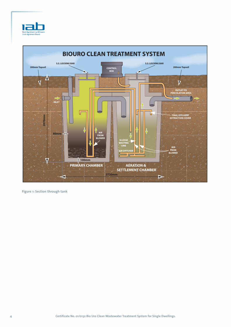
2.1 PRODUCT DESCRIPTION2.1.1 System Details
The Bio Uro Clean Wastewater Treatment System
utilises a Sequential Batch Reactor (SBR) process to
treat domestic wastewater from dwellings with a
population equivalent of up to six persons.
The unit is formed from two Grade 30 N precast
reinforced concrete cylinders, standing on end. Each
chamber is accessed via an integral precast concrete
turret and precast concrete cover. A polypropylene
control box sits above the tanks.
All functions within the unit, ie level sensors, airlift
pumps, air bubble diffuser, timing etc are controlled
by a Programmable Logic Controller (PLC). Effluent is
pumped through the unit by an air compressor,
which also supplies the air diffuser. The PLC and
compressor are housed in a waterproof moulded
polyethylene kiosk, mounted above the unit. The
compressor operates on an intermittent basis in
accordance with a predefined programme. The
compressor and level sensor relays are protected by
overload circuit breakers.
The unit operates off a normal domestic power
supply, and is connected to the dwelling served by a
residual current circuit breaker. The control kiosk is
provided with high ventilation grills. It is fitted with a
cooling fan to prevent overheating. The kiosk can be
locked to prevent unauthorised access. There are two
warning lights on the front panel of the kiosk, to
indicate the operational status of the unit.
Inlet and outlet pipe connections are provided.
The unit is vented through the rodding eye.
The unit is accessed via two lockable, pedestrian duty
concrete access covers, designed to be flush with
ground level.
Discharge from the tank is by gravity.
Provision can be made for pumped discharge, by
incorporating an additional pump if required.
Pumped systems shall be designed by a competent
person. Adequate provision should be made for
storage in the event of pump failure. This is outside
the scope of this certificate.
2.1.2 TreatmentTreatment is carried out in two phases, in the primary
chamber and treatment chamber, as follows:
Zone 1 - Primary treatment:
Domestic wastewater enters the primary chamber,
which has adequate capacity to accommodate and
balance out peak flows (eg morning or evening).
Here, heavy solids settle out on the base of the
compartment, where they remain until desludging.
Lighter debris and grease rise to the surface to form a
crust. At regular intervals (6.0 hours), a
predetermined volume of the settled liquid is
transferred by airlift pump, to the treatment
chamber.
Zone 2 - Biological treatment/aeration:When the volume of effluent in the aeration and
settlement chamber reaches a predefined level, the
air supply from the compressor is diverted to the air
bubble diffuser, located on the base of the chamber.
The liquid is aerated for four hours, enabling the
cultivation of colonies of bacteria (biomass), which
break down the organic matter. Following a settling
period of two hours, the clarified effluent is pumped
for discharge by gravity to the percolation area. The
treatment cycle then recommences, providing there is
sufficient volume of wastewater in the primary
chamber to constitute a batch.
When there is insufficient inflow of wastewater to
the primary chamber within the cycle time, the unit
switches to an alternative cycle or ‘holiday mode’ ie
the effluent in the second chamber is aerated for two
hours, followed by two hours of settlement. This cycle
continues until adequate volume of wastewater is
detected in the primary chamber and normal
operation resumes.
Part Two / Technical Specification and Control Data 2
Certificate No. 01/0132 Bio Uro Clean Wastewater Treatment System for Single Dwellings.4
Figure 1: Section through tank
Table 1.: Bio Uro Clean Wastewater Treatment System – basic information
Treatment capacity 4080 litres
Primary chamber 2040 litres
treatment capacity
Treatment chamber 2040 litres
capacity
Design population 6 PE
Chamber Diameter 1170 mm
Overall length 2730 mm
Total Height 2070 mm
Weight (empty) 2000 kg
Design flow rate 1200 litres/day
BOD load 0.36 kg/day
Inlet invert to base 1890 mm
Outlet invert to base 1890 mm
Ground level to
inlet/outlet invert level 600 mm
Compressor motor rating 0.49 amps
De-sludge period 1 year minimum
Retention time
(based on design flow) 80 hours
2.2 MANUFACTURE2.2.1 General
The chambers are cast from G30N concrete (wall
thickness 80 mm; base thickness 100 mm). The base
incorporates A252 mesh reinforcement with a
minimum of 30 mm cover. The walls are reinforced in
the vertical direction, with four M8 bars bent in the
form of an inverted ‘v’, to provide lifting hooks for
proprietary lifting sockets.
All plumbing joints are formed using push fit
connections and are solvent sealed. The internal pipe
work and the air diffuser are fitted prior to final testing.
The control kiosk/air compressor unit is bolted to the
tank cover. The inlet and outlet pipes and connections
are fitted and labels applied.
2.2.2 Product rangeThe system is designed to collect domestic
wastewater from dwellings having a population
equivalent of up to six persons. System details are
shown in Table 1.
Ancillary items• Programmable logic controller (PLC)
• 110 mm uPVC drainage pipes and sockets to BS
4660: 2000 Thermoplastics ancillary fittings ofnominal sizes 110 and 160 for below ground gravitydrainage and sewerage
• UPVC internal pipe work
• Air diffuser assembly
• Air compressor
• Electrical control panel, float switch and alarm
• electrical cable glands
All components in contact with effluent are made of
stainless steel, uPVC or polyethylene.
Quality controlThe Certificate holder operates a quality
management system and continuous quality control
is exercised during manufacture. Quality checks
include tank wall thickness, visual inspection and
water tightness testing.
2.3 DELIVERY, STORAGE AND MARKINGThe unit is delivered to site fully assembled. It shall
be lifted with a certified lifting frame in accordance
with the Certificate holder’s instructions. Off loading
shall be carefully supervised and lifting equipment
shall be selected taking into account the unit weight,
dimensions and the distance of lift required (see
Table 1). All lifting equipment and procedures shall
comply with the requirements of the Safety, Health
and Welfare at Work Act 1989. The Certificate holder’s
instructions shall be followed to avoid damage to the
tank during off-loading and installation.
Each unit bears a unique serial number, for
traceability purposes, which is located on an
identification plate in the control box. The Certificate
holder’s details, model type and population
equivalent capacity, are listed on the cover, such that
all are clearly visible once installation is complete.
The tank is supplied with full installation instructions
and is labelled with the IAB identification Mark
incorporating the number of this Certificate.
The tank should be stored upright, on level ground,
with the cover in place to prevent ingress of water.
2.4 INSTALLATION2.4.1 General
Bio Uro Clean offers an installation supervision and
commissioning service. Installation shall be carried
out by competent persons.
Bio Uro Clean recommends that a competent person,
e.g. an appropriately qualified and experienced
engineer or surveyor, conduct a site suitability
assessment. Based on this assessment, the
Certificate No. 01/0132 Bio Uro Clean Wastewater Treatment System for Single Dwellings. 5
Certificate No. 01/0132 Bio Uro Clean Wastewater Treatment System for Single Dwellings.6
competent person should design and supervise
installation and commissioning of the unit.
Bio Uro Clean supplies detailed installation instructions.
It is Bio Uro Clean’s policy to
a) deliver, off load, and lift each unit into the excavation
provided, using specially selected lifting equipment;
b) supervise the installation;
c) commission all systems before use.
2.4.2 Electrical WorksElectrical connections shall be strictly in accordance
with the Certificate holder’s instructions, ET101: 2002
National Rules for Electrical Installations (3rd Edition)incorporating Amendment No. 1 2001 and ET 207: 2003
Guide to the National Rules for Electrical InstallationsAs Applicable To Domestic & Similar Installations,
published by the Electro-Technical Council of Ireland
(ETCI). A competent person, using materials suitable
for the purpose (i.e. a 2.5 mm2 three core SWA cable
complete with earth), shall carry out electrical
connections, from the mains supply board.
Electrical cables shall be protected from accidental
damage e.g. by a suitable conduit. It is recommended
that the control panel is clearly visible from a suitable
location within the house.
2.4.3 Site WorksThe excavation shall be of sufficient size to permit
placement of the unit and back filling and to allow
for timbering and sheeting as necessary to meet the
requirements of The Safety, Health and Welfare at
Work Act, 1989. There should be sufficient area on
site to permit excavation, dumping of excess spoil,
backfilling, handling and installation, without causing
damage to the unit or the ancillary equipment.
It is essential to prevent damage due to superimposed
loading, from vehicles or site traffic. A suitable fence
shall be erected around the unit to restrict loading.
The distance between the fence and the unit should
be equal to or greater than the depth of excavation
for the unit.
Care shall be taken to prevent accidental damage
arising from blows from tools, or concentrated
pressure on the shell from levering etc.
Similarly, sharp corners, rocks and stones shall be kept
clear of the unit. This shall be borne in mind when
back filling, as the resultant load of a sharp object
could fracture the unit.
The tank should not be lifted if it contains water.
2.4.4 DesignThe potential suitability of a site, for the installation
of such a system, shall be assessed using the
methodology outlined in the EPA Wastewatertreatment manual – Treatment Systems for SingleHouses 2000. The ground water protection responses
set out in ‘Groundwater Protection Responses for on-site Wastewater Systems for Single Houses’ published by
EPA/DoELG/GSI (2001) should be used in the desk study
assessment of the site, to give an early indication of
the suitability of the site for such a system.
The system should only be installed where acompetent authority determines the groundconditions, and the water table levels, to beadequate to support the tank, and to provide fordisposal of the effluent in accordance with relevantregulations. The system should not be installed inunsuitable ground conditions.
Where poor ground conditions prevail, e.g. soft
ground or shrinking clay, further advice must be
sought from a competent person, to establish if the
ground is adequate to support the tank and prevent
differential settlement.
Good ground working practice shall be followed,
particularly with regard to the gradient on drainage
pipe runs. The inlet pipe should have a gradient of
between 1:40 and 1:60. The outfall pipe should have a
final gradient of between 1:70 and 1:200.
Storm water run-off e.g. from roofs or paved areas
shall be excluded from the system.
The system shall not be installed in areas liable to
localised flooding, unless adequate additional
protection is provided in accordance with the
Certificate holder’s instructions.
Adequate provision should be made for access,
inspection and maintenance, in the drainage system
upstream and downstream of the unit, through the
provision of manholes, distribution chambers etc.
Adequate provision shall be made for ventilation, to
ensure that noxious odours and dangerous gases
can escape.
2.4.5 Health and SafetyExcavation, placing and backfilling should be carried
out strictly in accordance with the requirements of
the Safety, Health and Welfare at Work Act 1989 and
all other relevant legislative requirements.
2.4.6 Procedurea) Equipment and materials
It is recommended that all plant and materials
necessary for the installation should be on site
before excavation commences.
b) Tank Installation – dry siteA dry site is defined as one where the local water table
never rises above the base of the treatment unit.
system. Suitable adapters shall be used for
connection to other types of pipe work.
e) DuctingA 100 mm uPVC duct should be laid from the marked
connection point on the unit to the power supply.
f) Completion of backfillingWhen connections to drainage pipe work are
complete and ducting in place, continue
backfilling, terminating approximately 200 mm
below ground level. The remaining backfilling
should be completed to ground level, using
selected non-angular excavated material or topsoil.
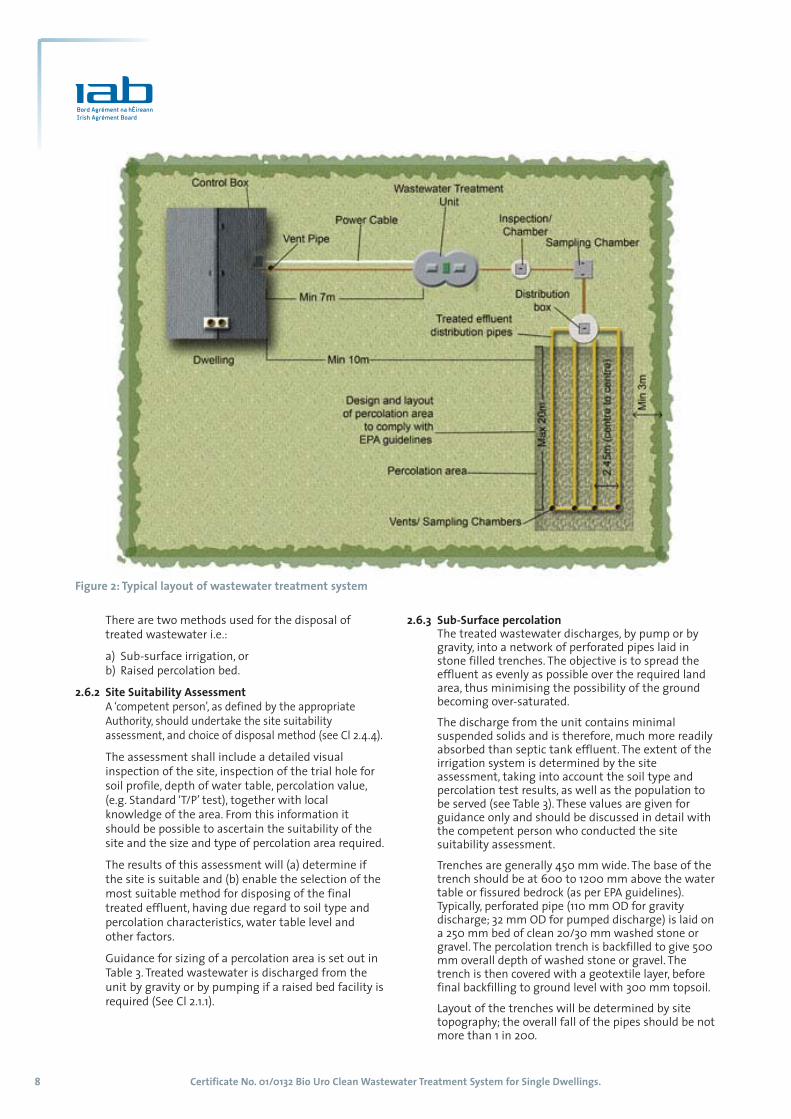
2.5 LOCATIONThe units should be sited so that adequate access is
available for safe installation, subsequent
maintenance and de-sludging of the unit. De-
sludging should be carried out by means of a de-
sludging tanker, which requires access to within 30m
of the unit. The minimum separation distances given
in Table 2 apply.
1. The depth of excavation to accommodate the unit shall be takeninto account when determining this distance. The separationdistance should be such that the excavation does not undermineadjacent buildings, roads or walls. This distance should be notless than 1.5 times the excavation depth.
2. The separation distance should be not less than 30 metresexcept in the case of very free draining soils or gravels, where aminimum distance of 40 metres should be maintained. Theirrigation area should be down hill of any nearby well. Where thisis not possible, a separation distance of at least 100 metres shallapply. For further details see Ground Water Protection Responsesfor On-Site Waste Water Systems for Single Houses published byEPA/DoELG/GSI (2001).
3. These minimum permissible distances are for guidance only. A‘Competent Person’ should assess each site on its own merits.However, where the site permits, irrigation areas should belocated at greater separation distances from the dwelling. Alsowhere possible on sloping sites, the irrigation area should bedown slope from the dwelling.
2.6 TREATED WASTE WATER DISPOSAL2.6.1 General Principles
The unit produces a fully treated wastewater,
(BOD <20 mg/l; suspended solids <30 mg/l), which is
more easily absorbed into soil strata than septic
tank effluent.
Table 2: Minimum Separation Distance (m)Unit Irrigation Area
Dwelling served 71 103
Adjacent dwelling 71 103
Wall 3.51 3
Road 41 4
Site boundary 3.51 3
Potable 10 30-1002
Water source
Certificate No. 01/0132 Bio Uro Clean Wastewater Treatment System for Single Dwellings. 7
The tanks shall be installed as follows:
1. A pit should be excavated to a depth to suit the
invert level of the incoming drain – see certificate
holder’s instructions.
2. Care shall be taken to eliminate voids and soft
spots beneath the tank. All water, sharp stones
and boulders shall be removed from the
excavation. The unit may be bedded on firm
excavated ground, or where necessary eg poor
ground, on to concrete, which is haunched up
around the base of the unit. The concrete shall be
of sufficient grade (minimum 25N) and thickness
(minimum 150 mm) to ensure that the unit is
adequately supported with due regard to subsoil
conditions and imposed loads.
3. The tank is carefully lowered onto the excavation
base, using purpose made lifting equipment, which
is attached to four lugs cast into the tank. The tank
shall be level horizontally and truly vertical.
4. The inlet should be in line with the drain from the
premises to be served. Care should be taken to
prevent damage to external flanges or pipe work
and to ensure correct orientation of the outlet
pipe work.
5. The excavation is then backfilled using selected
self-compacting pea gravel or suitable granular
material, (compaction factor of 0.2 or less, all rocks
and large stones removed). The backfill must be
carefully consolidated to prevent local stress
concentrations and uneven transfer of ground
loads. The system should be ballasted when
backfilling. The backfilling should be scheduled to
permit connection of drainage pipework.
c) Additional requirements for wet sitesA wet site is defined as one where the local water
table can rise above the base of the treatment
unit. Installation in a wet site may be precluded bysite considerations in relation to effluent disposal.
6. A 250 mm hardcore sub-base is laid, compacted
and levelled.
7. The excavation is kept dry by pumping excess water
using a site pump/sump hole/suction hose arrangement.
Dewatering should be continued for as long as
necessary and at least until the concrete has set.
8. The excavation is then lined with a continuous
layer of 1200 gauge polyethylene sheet. The
installation should then continue in accordance with
the requirements for dry sites. The grade and
thickness of the concrete base should be designed to
suit site conditions (minimum 250 thick, grade 25N).
d) Drainage ConnectionsThe tank is provided, at the inlet and outlet, with
110mm uPVC pipes connections to BS 4660. These
should be connected, via a flexible connection to
allow for differential movement, (300mm length
of pipe with flexible joints), to the drainage
Certificate No. 01/0132 Bio Uro Clean Wastewater Treatment System for Single Dwellings.8
There are two methods used for the disposal of
treated wastewater i.e.:
a) Sub-surface irrigation, or
b) Raised percolation bed.
2.6.2 Site Suitability AssessmentA ‘competent person’, as defined by the appropriate
Authority, should undertake the site suitability
assessment, and choice of disposal method (see Cl 2.4.4).
The assessment shall include a detailed visual
inspection of the site, inspection of the trial hole for
soil profile, depth of water table, percolation value,
(e.g. Standard ‘T/P’ test), together with local
knowledge of the area. From this information it
should be possible to ascertain the suitability of the
site and the size and type of percolation area required.
The results of this assessment will (a) determine if
the site is suitable and (b) enable the selection of the
most suitable method for disposing of the final
treated effluent, having due regard to soil type and
percolation characteristics, water table level and
other factors.
Guidance for sizing of a percolation area is set out in
Table 3. Treated wastewater is discharged from the
unit by gravity or by pumping if a raised bed facility is
required (See Cl 2.1.1).
2.6.3 Sub-Surface percolationThe treated wastewater discharges, by pump or bygravity, into a network of perforated pipes laid instone filled trenches. The objective is to spread theeffluent as evenly as possible over the required landarea, thus minimising the possibility of the groundbecoming over-saturated.
The discharge from the unit contains minimalsuspended solids and is therefore, much more readilyabsorbed than septic tank effluent. The extent of theirrigation system is determined by the siteassessment, taking into account the soil type andpercolation test results, as well as the population tobe served (see Table 3). These values are given forguidance only and should be discussed in detail withthe competent person who conducted the sitesuitability assessment.
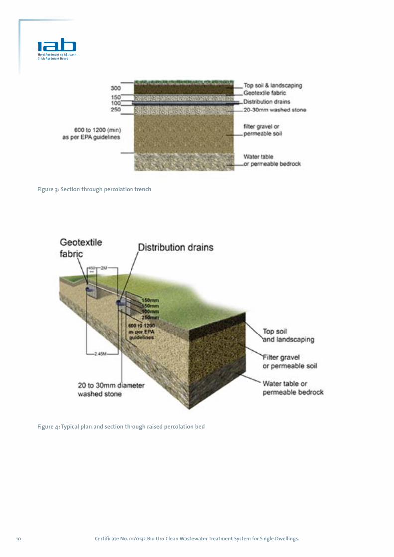
Trenches are generally 450 mm wide. The base of thetrench should be at 600 to 1200 mm above the watertable or fissured bedrock (as per EPA guidelines).Typically, perforated pipe (110 mm OD for gravitydischarge; 32 mm OD for pumped discharge) is laid ona 250 mm bed of clean 20/30 mm washed stone orgravel. The percolation trench is backfilled to give 500mm overall depth of washed stone or gravel. Thetrench is then covered with a geotextile layer, beforefinal backfilling to ground level with 300 mm topsoil.
Layout of the trenches will be determined by sitetopography; the overall fall of the pipes should be notmore than 1 in 200.
Figure 2: Typical layout of wastewater treatment system
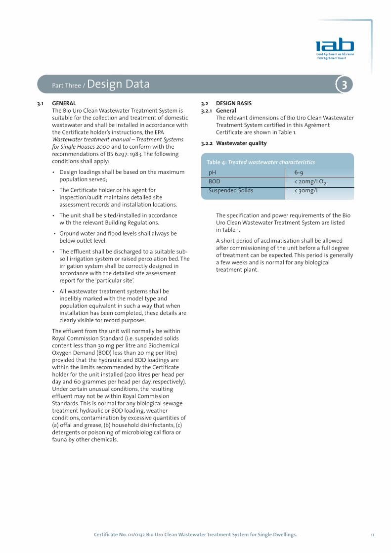
2.6.4 Raised percolation bedWhere raised percolation beds are required e.g. thintopsoils and/or rock or water table close to thesurface, the capacity of the pump needs to beselected to suit (See Cl 2.1.1).
The percolation trench construction is similar to thatspecified for sub-surface percolation. The base of thepercolation trench should be at least 600 to 1200mm above the highest water table or fissuredbedrock (as per EPA guidelines). The perforated pipe islaid on a 250 mm bed of clean 20/30 washed stone orgravel. The trench is then backfilled to give an overalldepth of 500mm. The trench is covered with ageotextile layer, before backfilling to ground levelwith 150 mm minimum of good quality topsoil.
2.6.5 Provision for inspection of percolation areaFor monitoring, sampling and maintenance purposes,access to the effluent percolation systems should beprovided at the end of each irrigation or filter trenchvia a suitably constructed inspection chamber.
2.6.6 Further treatmentIn some instances (e.g. proximity to a drinking watersource), the effluent may require "polishing" beforedischarge, to reduce coliform bacteria levels. Acommonly used method is to pass the dischargethrough a sand filter. In this situation, the dischargeis pumped to the sand filter using an effluent pumpset capable of discharging in 180 litre doses. Polishingfilters can be partly or wholly above ground soil,covered or open. A typical filter serving a 4-personhousehold would have a plan area of 8 m2 to 20 m2,depending on design and type of sand used.
Where part of the polishing system is exposed aboveground, care shall be taken to ensure there is no riskof casual or accidental access to the area.
Table 3: Guidance for sizing of percolation area (linear metres of percolation pipe)
Population T/P values T/P values served 21-50* 1-20*
Loading at Loading at25l/ m2 per day 50l/ m2 per day
3 48 24
4 64 32
5 80 40
6 96 48
* based on 450 mm trench width
2.7 ALARM A visual alarm is supplied to warn of power failure.The alarm should be clearly visible from thehouse/driveway.
2.8 COMMISSIONINGBio Uro Clean shall carry out commissioning, afterinstallation is complete and all services are connected.
2.9 SERVICING AND MAINTENANCEBio Uro Clean offers service and maintenance contractsand can also carry out repair work.
2.10 ENCLOSURE The area around the tank and percolation area shouldbe fenced off to protect it from farm animals andother unwanted traffic.
Certificate No. 01/0132 Bio Uro Clean Wastewater Treatment System for Single Dwellings. 9
Certificate No. 01/0132 Bio Uro Clean Wastewater Treatment System for Single Dwellings.10
Figure 3: Section through percolation trench
Figure 4: Typical plan and section through raised percolation bed
3.1 GENERALThe Bio Uro Clean Wastewater Treatment System is
suitable for the collection and treatment of domestic
wastewater and shall be installed in accordance with
the Certificate holder’s instructions, the EPA
Wastewater treatment manual – Treatment Systemsfor Single Houses 2000 and to conform with the
recommendations of BS 6297: 1983. The following
conditions shall apply:
• Design loadings shall be based on the maximum
population served;
• The Certificate holder or his agent for
inspection/audit maintains detailed site
assessment records and installation locations.
• The unit shall be sited/installed in accordance
with the relevant Building Regulations.
• Ground water and flood levels shall always be
below outlet level.
• The effluent shall be discharged to a suitable sub-
soil irrigation system or raised percolation bed. The
irrigation system shall be correctly designed in
accordance with the detailed site assessment
report for the ‘particular site’.
• All wastewater treatment systems shall be
indelibly marked with the model type and
population equivalent in such a way that when
installation has been completed, these details are
clearly visible for record purposes.
The effluent from the unit will normally be within
Royal Commission Standard (i.e. suspended solids
content less than 30 mg per litre and Biochemical
Oxygen Demand (BOD) less than 20 mg per litre)
provided that the hydraulic and BOD loadings are
within the limits recommended by the Certificate
holder for the unit installed (200 litres per head per
day and 60 grammes per head per day, respectively).
Under certain unusual conditions, the resulting
effluent may not be within Royal Commission
Standards. This is normal for any biological sewage
treatment hydraulic or BOD loading, weather
conditions, contamination by excessive quantities of
(a) offal and grease, (b) household disinfectants, (c)
detergents or poisoning of microbiological flora or
fauna by other chemicals.
3.2 DESIGN BASIS3.2.1 General
The relevant dimensions of Bio Uro Clean Wastewater
Treatment System certified in this Agrément
Certificate are shown in Table 1.
3.2.2 Wastewater quality
The specification and power requirements of the Bio
Uro Clean Wastewater Treatment System are listed
in Table 1.
A short period of acclimatisation shall be allowed
after commissioning of the unit before a full degree
of treatment can be expected. This period is generally
a few weeks and is normal for any biological
treatment plant.
Part Three / Design Data 3
Table 4: Treated wastewater characteristics pH 6-9
BOD < 20mg/I O2
Suspended Solids < 30mg/I
Certificate No. 01/0132 Bio Uro Clean Wastewater Treatment System for Single Dwellings. 11

Certificate No. 01/0132 Bio Uro Clean Wastewater Treatment System for Single Dwellings.12
4.1 ENVIRONMENTAL ASSESSMENTThe treated wastewater from a number of working units
has been monitored. The test results show that values
stated for the parameters listed in Table 4 are consistently
achievable over a range of operating conditions.
4.2 STRENGTHThe Certificate holder’s design has been assessed as
satisfactory. The unit has adequate resistance to
resist damage from minor impacts during handling
but it shall be slung in accordance with the
Certificate holder’s instructions.
The unit has sufficient structural strength to resist
soil loads in non-cohesive dry soils, but it is
recommended that excavations are backfilled in
accordance with 2.4.6.b) and c), to resist uplift of
units, due to buoyancy. The cover and frame assembly
is suitable for pedestrian traffic only.
4.3 WATERTIGHTNESSThe system, when correctly installed, has been
assessed as fully capable of preventing seepage
either into or from the surrounding soil. The pipe
joints, when correctly made, will be watertight.
4.4 DURABILITYIn the opinion of the IAB the product will have a life
in excess of 50 years when installed in accordance
with this Certificate. The mechanical and electrical
components may require replacement within the
design life.
4.5 MAINTENANCECleaning and maintenance should be carried out in
accordance with the Certificate holder’s Operation
and Maintenance Instructions.
Bio Uro Clean strongly recommends that access to
the tank interior be restricted to Bio Uro Clean
trained operatives or authorised and competent
maintenance contractors.
Access to the tank interior is via the manhole covers
provided, using the appropriate tools.
Both the compressor and the associated pipe work
can also be accessed for removal and cleaning.
The tank is easily de-sludged, in the conventional manner
by a suction tanker. De-sludging should be carried out in
accordance with the Certificate holder’s instructions.
Summary of maintenance instructionsThe Bio Uro Clean Wastewater Treatment System is
de-sludged by a suction tanker. Care shall be taken to
avoid damage by the hose nozzle. The primary
chamber shall be de-sludged, through the sludge
removal access, in accordance with the Certificate
holder’s recommendations.
Frequency of inspection
It is recommended that the homeowner should conduct
an inspection of the system regularly, and at least every
six months, in accordance with the Certificate holder’s
‘Operation and Maintenance instructions’.
4.6 SAFETY4.6.1 Safety of personnel
The access covers can be securely fixed and lockable,
to prevent unauthorised access. The access covers
shall not be left off an unattended tank.
Sewage treatment plants are potentially dangerous,
particularly when being de-sludged. De-sludging
shall never be carried out alone. If it is necessary to
enter the unit, adequate safety precautions shall be
made to ensure the safety of personnel involved.
Naked lights, which can cause explosions, shall not be
used in the vicinity of the tanks.
The unit should be positioned, or marked, or
protected, to prevent superimposed loading or
accidental impact by vehicles.
4.7 TESTS AND ASSESSMENTS WERE CARRIED OUT TODETERMINE THE FOLLOWING:• Watertightness.
• Strength of cover and frame assemblies.
• Resistance of units to hydrostatic and ground pressure.
• Resistance to flotation.
• Environmental performance.
• Concrete cube strength.
4.8 OTHER INVESTIGATIONS(i) The manufacturing process was examined
including the methods adopted for quality
control, and details were obtained of the quality
and composition of the materials used.
(ii) An assessment of the results of sample analysis
of effluent, was undertaken.
(iii) An assessment of the tank was made in relation
to degradation of mechanical properties owing
to exposure to sewage, ground water, dissolved
salts and dilute acids or alkalis; long-term
loading conditions.
(iv) Site visits were conducted to assess the
practicability of installation.
(v) Bought in components were assessed for
suitability for use.
No failures of the product in use have been reported
to the IAB.
Part Four / Technical investigations 4
Certificate No. 01/0132 Bio Uro Clean Wastewater Treatment System for Single Dwellings. 13
5.1 National Standards Authority of Ireland ("NSAI")
following consultation with the Irish Agrément Board
("IAB") has assessed the performance and method of
installation of the product/process and the quality of
the materials used in its manufacture and certifies
the product/process to be fit for the use for which it
is certified provided that it is manufactured, installed,
used and maintained in accordance with the descriptions
and specifications set out in this Certificate and in
accordance with the manufacturer's instructions and
usual trade practice. This Certificate shall remain
valid for five years so long as:
(a) the specification of the product is unchanged.
(b)the Building Regulations 1997 to 2002 and
any other regulation or standard applicable
to the product/process, its use or installation
remains unchanged.
(c) the product continues to be assessed for the
quality of its manufacture and marking by NSAI.
(d) no new information becomes available which in
the opinion of the NSAI, would preclude the
granting of the Certificate.
(e) the product or process continues to be manufactured,
installed, used and maintained in accordance with
the description, specifications and safety
recommendations set out in this certificate.
(f) the registration and/or surveillance fees due to
IAB are paid.
5.2 The IAB mark and certification number may only be
used on or in relation to product/processes in respect
of which a valid Certificate exists. If the Certificate
becomes invalid the Certificate holder must not use
the IAB mark and certification number and must
remove them from the products already marked.
5.3 In granting Certification, the NSAI makes no
representation as to;
(a) the absence or presence of patent rights
subsisting in the product/process; or
(b)the legal right of the Certificate holder to market,
install or maintain the product/process; or
(c) whether individual products have been
manufactured or installed by the Certificate
holder in accordance with the descriptions
and specifications set out in this Certificate.
5.4 This Certificate does not comprise installation
instructions and does not replace the manufacturer's
directions or any professional or trade advice relating
to use and installation which may be appropriate.
5.5 Any recommendations contained in this Certificate
relating to the safe use of the certified product/process
are preconditions to the validity of the Certificate.
However the NSAI does not certify that the
manufacture or installation of the certified product
or process in accordance with the descriptions and
specifications set out in this Certificate will satisfy
the requirements of the Safety, Health and Welfare at
Work Act. 1989, or of any other current or future
common law duty of care owed by the manufacturer
or by the Certificate holder.
5.6 The NSAI is not responsible to any person or body
for loss or damage including personal injury arising
as a direct or indirect result of the use of this
product or process.
5.7 Where reference is made in this Certificate to any
Act of the Oireachtas, Regulation made thereunder,
Statutory Instrument, Code of Practice, National
Standards, Manufacturer's instructions, or similar
publication, it shall be construed as reference to such
publication in the form in which it is in force at the
date of this Certification.
Part Five / Conditions of Certification 5

Certificate No. 01/0132 Bio Uro Clean Wastewater Treatment System for Single Dwellings.14
THE IRISH AGRÉMENT BOARD THE IRISH AGRÉMENT BOARD THE IRISH AGRÉMENT BOARD THE IRISH AGRÉMENT BOARD THE IRISH AGRÉMENT BOARD THE IRISHAGRÉMENT BOARD THE IRISH AGRÉMENT BOARD THE IRISH AGRÉMENT BOARD THE IRISH AGRÉMENT BOARD THE IRISH AGRÉMENT BOARD THE IRISH AGRÉMENTBOARD THE IRISH AGRÉMENT BOARD THE IRISH AGRÉMENT BOARD THE IRISH AGRÉMENT BOARD THE IRISH AGRÉMENT BOARD THE IRISH AGRÉMENT BOARDTHE IRISH AGRÉMENT BOARD THE IRISH AGRÉMENT BOARD THE IRISH AGRÉMENT BOARD THE IRISH AGRÉMENT BOARD THE IRISH AGRÉMENT BOARD THE IRISHAGRÉMENT BOARD THE IRISH AGRÉMENT BOARD THE IRISH AGRÉMENT BOARD THE IRISH AGRÉMENT BOARD THE IRISH AGRÉMENT BOARD THE IRISH AGRÉMENTBOARD THE IRISH AGRÉMENT BOARD THE IRISH AGRÉMENT BOARD THE IRISH AGRÉMENT BOARD THE IRISH AGRÉMENT BOARD THE IRISH AGRÉMENT BOARDTHE IRISH AGRÉMENT BOARD THE IRISH AGRÉMENT BOARD THE IRISH AGRÉMENT BOARD THE IRISH AGRÉMENT BOARD THE IRISH AGRÉMENT BOARD THE IRISHAGRÉMENT BOARD THE IRISH AGRÉMENT BOARD THE IRISH AGRÉMENT BOARD THE IRISH AGRÉMENT BOARD THE IRISH AGRÉMENT BOARD THE IRISH AGRÉMENTBOARD THE IRISH AGRÉMENT BOARD THE IRISH AGRÉMENT BOARD THE IRISH AGRÉMENT BOARD THE IRISH AGRÉMENT BOARD THE IRISH AGRÉMENT BOARDTHE IRISH AGRÉMENT BOARD THE IRISH AGRÉMENT BOARD THE IRISH AGRÉMENT BOARD THE IRISH AGRÉMENT BOARD THE IRISH AGRÉMENT BOARD THE IRISHAGRÉMENT BOARD THE IRISH AGRÉMENT BOARD THE IRISH AGRÉMENT BOARD THE IRISH AGRÉMENT BOARD THE IRISH AGRÉMENT BOARD THE IRISH AGRÉMENTBOARD THE IRISH AGRÉMENT BOARD THE IRISH AGRÉMENT BOARD THE IRISH AGRÉMENT BOARD THE IRISH AGRÉMENT BOARD THE IRISH AGRÉMENT BOARDTHE IRISH AGRÉMENT BOARD THE IRISH AGRÉMENT BOARD THE IRISH AGRÉMENT BOARD THE IRISH AGRÉMENT BOARD THE IRISH AGRÉMENT BOARD THE IRISHAGRÉMENT BOARD THE IRISH AGRÉMENT BOARD THE IRISH AGRÉMENT BOARD THE IRISH AGRÉMENT BOARD THE IRISH AGRÉMENT BOARD THE IRISH AGRÉMENTBOARD THE IRISH AGRÉMENT BOARD THE IRISH AGRÉMENT BOARD THE IRISH AGRÉMENT BOARD THE IRISH AGRÉMENT BOARD THE IRISH AGRÉMENT BOARDTHE IRISH AGRÉMENT BOARD THE IRISH AGRÉMENT BOARD THE IRISH AGRÉMENT BOARD THE IRISH AGRÉMENT BOARD THE IRISH AGRÉMENT BOARD THE IRISHAGRÉMENT BOARD THE IRISH AGRÉMENT BOARD THE IRISH AGRÉMENT BOARD THE IRISH AGRÉMENT BOARD THE IRISH AGRÉMENT BOARD THE IRISH AGRÉMENTBOARD THE IRISH AGRÉMENT BOARD THE IRISH AGRÉMENT BOARD THE IRISH AGRÉMENT BOARD THE IRISH AGRÉMENT BOARD THE IRISH AGRÉMENT BOARDTHE IRISH AGRÉMENT BOARD THE IRISH AGRÉMENT BOARD THE IRISH AGRÉMENT BOARD THE IRISH AGRÉMENT BOARD THE IRISH AGRÉMENT BOARD THE IRISHAGRÉMENT BOARD THE IRISH AGRÉMENT BOARD THE IRISH AGRÉMENT BOARD THE IRISH AGRÉMENT BOARD THE IRISH AGRÉMENT BOARD THE IRISH AGRÉMENTBOARD THE IRISH AGRÉMENT BOARD THE IRISH AGRÉMENT BOARD THE IRISH AGRÉMENT BOARD THE IRISH AGRÉMENT BOARD THE IRISH AGRÉMENT BOARDTHE IRISH AGRÉMENT BOARD THE IRISH AGRÉMENT BOARD THE IRISH AGRÉMENT BOARD THE IRISH AGRÉMENT BOARD THE IRISH AGRÉMENT BOARD THE IRISHAGRÉMENT BOARD THE IRISH AGRÉMENT BOARD THE IRISH AGRÉMENT BOARD THE IRISH AGRÉMENT BOARD THE IRISH AGRÉMENT BOARD THE IRISH AGRÉMENTBOARD THE IRISH AGRÉMENT BOARD THE IRISH AGRÉMENT BOARD THE IRISH AGRÉMENT BOARD THE IRISH AGRÉMENT BOARD THE IRISH AGRÉMENT BOARDTHE IRISH AGRÉMENT BOARD THE IRISH AGRÉMENT BOARD THE IRISH AGRÉMENT BOARD THE IRISH AGRÉMENT BOARD THE IRISH AGRÉMENT BOARD THE IRISHAGRÉMENT BOARD THE IRISH AGRÉMENT BOARD THE IRISH AGRÉMENT BOARD THE IRISH AGRÉMENT BOARD THE IRISH AGRÉMENT BOARD THE IRISH AGRÉMENTBOARD THE IRISH AGRÉMENT BOARD THE IRISH AGRÉMENT BOARD THE IRISH AGRÉMENT BOARD THE IRISH AGRÉMENT BOARD THE IRISH AGRÉMENT BOARDTHE IRISH AGRÉMENT BOARD THE IRISH AGRÉMENT BOARD THE IRISH AGRÉMENT BOARD THE IRISH AGRÉMENT BOARD THE IRISH AGRÉMENT BOARD THE IRISHAGRÉMENT BOARD THE IRISH AGRÉMENT BOARD THE IRISH AGRÉMENT BOARD THE IRISH AGRÉMENT BOARD THE IRISH AGRÉMENT BOARD THE IRISH AGRÉMENTBOARD THE IRISH AGRÉMENT BOARD THE IRISH AGRÉMENT BOARD THE IRISH AGRÉMENT BOARD THE IRISH AGRÉMENT BOARD THE IRISH AGRÉMENT BOARDTHE IRISH AGRÉMENT BOARD THE IRISH AGRÉMENT BOARD THE IRISH AGRÉMENT BOARD THE IRISH AGRÉMENT BOARD THE IRISH AGRÉMENT BOARD THE IRISHAGRÉMENT BOARD THE IRISH AGRÉMENT BOARD THE IRISH AGRÉMENT BOARD THE IRISH AGRÉMENT BOARD THE IRISH AGRÉMENT BOARD THE IRISH AGRÉMENTBOARD THE IRISH AGRÉMENT BOARD THE IRISH AGRÉMENT BOARD THE IRISH AGRÉMENT BOARD THE IRISH AGRÉMENT BOARD THE IRISH AGRÉMENT BOARDTHE IRISH AGRÉMENT BOARD THE IRISH AGRÉMENT BOARD THE IRISH AGRÉMENT BOARD THE IRISH AGRÉMENT BOARD THE IRISH AGRÉMENT BOARD THE IRISHAGRÉMENT BOARD THE IRISH AGRÉMENT BOARD THE IRISH AGRÉMENT BOARD THE IRISH AGRÉMENT BOARD THE IRISH AGRÉMENT BOARD THE IRISH AGRÉMENTBOARD THE IRISH AGRÉMENT BOARD THE IRISH AGRÉMENT BOARD THE IRISH AGRÉMENT BOARD THE IRISH AGRÉMENT BOARD THE IRISH AGRÉMENT BOARDTHE IRISH AGRÉMENT BOARD THE IRISH AGRÉMENT BOARD THE IRISH AGRÉMENT BOARD THE IRISH AGRÉMENT BOARD THE IRISH AGRÉMENT BOARD THE IRISHAGRÉMENT BOARD THE IRISH AGRÉMENT BOARD THE IRISH AGRÉMENT BOARD THE IRISH AGRÉMENT BOARD THE IRISH AGRÉMENT BOARD THE IRISH AGRÉMENTBOARD THE IRISH AGRÉMENT BOARD THE IRISH AGRÉMENT BOARD THE IRISH AGRÉMENT BOARD THE IRISH AGRÉMENT BOARD THE IRISH AGRÉMENT BOARDTHE IRISH AGRÉMENT BOARD THE IRISH AGRÉMENT BOARD THE IRISH AGRÉMENT BOARD THE IRISH AGRÉMENT BOARD THE IRISH AGRÉMENT BOARD THE IRISHAGRÉMENT BOARD THE IRISH AGRÉMENT BOARD THE IRISH AGRÉMENT BOARD THE IRISH AGRÉMENT BOARD THE IRISH AGRÉMENT BOARD THE IRISH AGRÉMENTBOARD THE IRISH AGRÉMENT BOARD THE IRISH AGRÉMENT BOARD THE IRISH AGRÉMENT BOARD THE IRISH AGRÉMENT BOARD THE IRISH AGRÉMENT BOARD THE IRISH AGRÉMENT BOARD THE IRISH AGRÉMENT BOARD THE IRISH AGRÉMENT BOARD THE IRISH AGRÉMENT BOARD THE IRISH AGRÉMENT BOARD THE IRISH
This Certificate No. 01/0132 is accordingly granted by the NSAI to Bio Uro Clean on behalf of
The Irish Agrément Board.
Date of Issue: April 2005
Signed
Chief Executive, NSAI
Readers may check that the status of this Certificate has not changed by contacting the Irish Agrément Board,
NSAI, Glasnevin, Dublin 9, Ireland. Telephone: (01) 807 3800. Fax: (01) 807 3842. www.nsai.ie
The Irish Agrément Board