biography - council on tall buildings and urban habitat
TRANSCRIPT
Title: Seismic Performance of Coupling Beam Damper System
Authors: Taesang Ahn, DongilYoungju Kim, DongilSang Dae Kim, Korea UniversityIntae Hwang, Korea University
Subject: Structural Engineering
Keywords: SeismicStructure
Publication Date: 2011
Original Publication: CTBUH 2011 Seoul Conference
Paper Type: 1. Book chapter/Part chapter2. Journal paper3. Conference proceeding4. Unpublished conference paper5. Magazine article6. Unpublished
© Council on Tall Buildings and Urban Habitat / Taesang Ahn; Youngju Kim; Sang Dae Kim; Intae Hwang
ctbuh.org/papers

MS03-10
Seismic Performance of Coupling Beam Damper System
TAESANG AHN1, YOUNGJU KIM2, SANGDAE KIM3, INTAE HWANG4
Dongil Rubber Belt (DRB) Co., Ltd., Seoul, Korea, [email protected] 1 Dongil Rubber Belt (DRB) Co., Ltd., Seoul, Korea, [email protected] 2
Korea University, Seoul, Korea, [email protected] 3
Korea University, Seoul, Korea, [email protected] 4
TAESANG AHN
Biography Tae-sang AHN has a bachelor's degree in architectural engineering and a master's degree in building construction from Seoul National University of Science and Technology. And he is pursuing a doctorate in building construction at the KOREA University. Tae-sang AHN got a certification for structural engineer in 2002. And he worked the company of structural design for 12years. Now he is a director of research in seismic isolation and vibration control engineering center from 2007. Abstract This paper describes an experimental investigation on the hysteresis behavior of new type of reinforced concrete coupling beam systems with energy dissipation devices, such as a steel damper and a friction damper. The coupling beam considered in this research is located between shear walls. The new system offers important advantages over the conventional systems: simpler detailing for the beams and the walls; increasing energy dissipative capacity, reducing damage to the structure. Metallic damper or friction damper are installed within beam to provide energy dissipation. Under lateral load, damper is in shear or bending. Test programs are carried out to investigate the hysteresis behavior and to evaluate the energy dissipation capacity. Test results show that the proposed systems show an excellent hysteretic behavior. In addition, the energy dissipation in these systems is concentrated only at the energy dissipation devices, while the inelastic behavior of the beams and walls is prevented through appropriate capacity design. Keywords: Coupling beam, Energy dissipation devices, Hysteresis behavior, Energy dissipation capacity
710
CTBUH 2011 World Conference October 10-12, 2011, COEX, Seoul, KOREA_____________________________________________________________________________________________________________________________________________________________
______________________________________________________________________________________________________________________________________________________________

1. INTRODUCTION The behavior of coupled shear walls is influenced by the stiffness, strength and ductility of coupling beams. Paulay (1971) showed that the failure of coupling beams with small length to depth ratios and conventional reinforcements is almost brittle. To improve the ductility of the coupling beams, using diagonal reinforcement in the beams has been proposed. However, diagonal reinforcement may increase the construction problems due to the congestion of reinforcement in some parts of the beams. In the recent years, hybrid coupled shear wall system is used for a coupled shear wall with steel coupling beams and reinforced concrete shear walls (Harries, 2001). However, the load transfer of steel coupling beam-wall connections with bearing failure has not been thoroughly investigated. It has also shown that the connection details of hybrid coupled shear wall system are exceedingly complex. In addition, recent research (Kurama et al., 2004) on steel coupling beams has shown that post-tensioning is an effective method to couple reinforced concrete walls in seismic regions. This paper investigates new type of reinforced concrete coupling beam systems with energy dissipation devices, such as a metallic damper and a friction damper. The principal function of this system is to reduce the inelastic energy dissipation demand on the framing system of a structure and to decrease damage to the framing system. Test programs for the proposed coupled shear wall system are carried out to investigate the hysteresis behavior and to evaluate the energy dissipation capacity. 2. Test Program 2. 1. Test specimens The overall specimens used in this research are summarized in Table 1, which presents beam type, target story drift and shear capacity of damper inserted in beam. The dimensions of specimens and damper details are shown in Figure 1. Specimen S1 is composed of the concrete shear walls and beam with conventional reinforcements, of which dimensions and details are typically used in apartment houses of Korea. Specimen S1 is the reference specimen to compare test result to other specimens. Specimens D1 and D2 are the coupled shear wall specimens with damping systems in beams. These two specimens are same details except for damper types. Specimen D1 has metallic damper as shown in Figure 1. The geometry of damper is an hourglass shape. The geometrical configuration of the plates is such that the bending moments produce a uniform flexural stress distribution over the full length of the plates. The hysteresis behavior of the proposed damper is similar to that of an ADAS damper (Whitaker et al., 1991). As the floor level above deforms laterally with respect to the coupled shear wall, the metallic yielding damper is subjected to a shear force. The shear forces induce bending moment and shear force over the length of the plates, with bending and shear occurring about the weak axis of the plate cross section. Specimen D2 is equipped with a friction damper in beam as shown in Figure 1. Friction dampers dissipate energy via sliding friction across the interface between two solid bodies, which include slotted-holed plates wherein a series of steel plates are bolted together with a specified clamping force. The clamping force is such that slip occurs at a prespecified friction force.
Table 7: Test specimen matrix
Specimen Beam type Target story drift Damper shear capacity
S1 Reinforced concrete beam - - -
D1 Steel damper 1.5 % 100 kN Yield strength based on test result of steel material
D2 Friction damper 1.5% 100 kN Friction strength 2. 2. Test setup A schematic diagram of test apparatus is shown in Figure 2. As shown in Figure 2, top and bottom of specimen was pinned to the strong beam and floor by hinge devices, respectively. The test specimens are loaded with a 1000kN hydraulic actuator to apply load to the strong beam. The displacement of all the specimens is controlled to follow similar displacement histories with progressively increasing amplitude. The loading protocol is shown in Figure 3, which is planned to load 3 cycles at each level. Target story drift of 1.5% was decided that as results of seismic analyses for typical apartment houses, the maximum drift ratios were observed under about 0.8% ~ 1%. This is because seismic level of Korea is the laterally low and medium.
711
CTBUH 2011 World Conference October 10-12, 2011, COEX, Seoul, KOREA_____________________________________________________________________________________________________________________________________________________________
______________________________________________________________________________________________________________________________________________________________
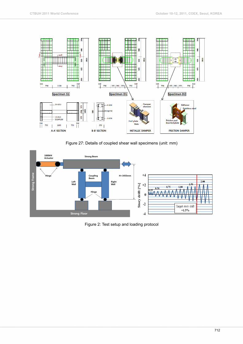
Figure 27: Details of coupled shear wall specimens (unit: mm)
Figure 2: Test setup and loading protocol
H=3455mm
Strong Beam1000kNActuator
LeftWall
RightWall
Coupling Beam
Hinge
Hinge
Strong Floor
Stro
ng
Fram
e
712
CTBUH 2011 World Conference October 10-12, 2011, COEX, Seoul, KOREA_____________________________________________________________________________________________________________________________________________________________
______________________________________________________________________________________________________________________________________________________________
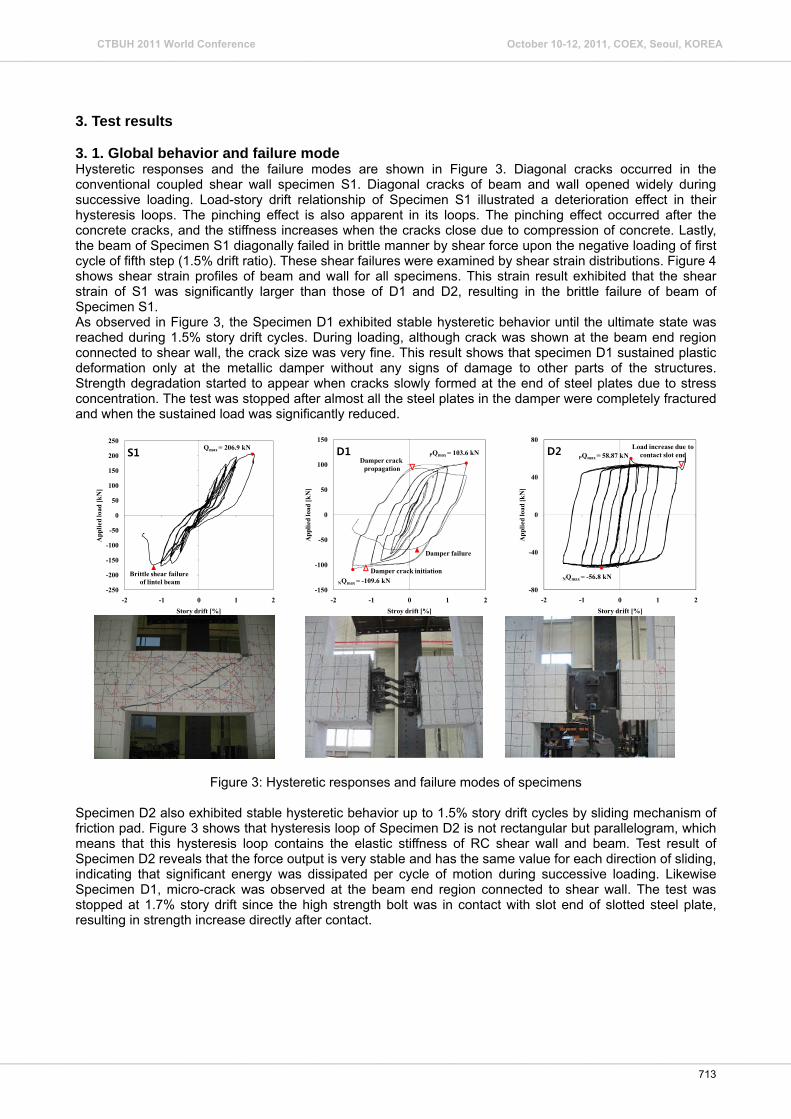
3. Test results 3. 1. Global behavior and failure mode Hysteretic responses and the failure modes are shown in Figure 3. Diagonal cracks occurred in the conventional coupled shear wall specimen S1. Diagonal cracks of beam and wall opened widely during successive loading. Load-story drift relationship of Specimen S1 illustrated a deterioration effect in their hysteresis loops. The pinching effect is also apparent in its loops. The pinching effect occurred after the concrete cracks, and the stiffness increases when the cracks close due to compression of concrete. Lastly, the beam of Specimen S1 diagonally failed in brittle manner by shear force upon the negative loading of first cycle of fifth step (1.5% drift ratio). These shear failures were examined by shear strain distributions. Figure 4 shows shear strain profiles of beam and wall for all specimens. This strain result exhibited that the shear strain of S1 was significantly larger than those of D1 and D2, resulting in the brittle failure of beam of Specimen S1. As observed in Figure 3, the Specimen D1 exhibited stable hysteretic behavior until the ultimate state was reached during 1.5% story drift cycles. During loading, although crack was shown at the beam end region connected to shear wall, the crack size was very fine. This result shows that specimen D1 sustained plastic deformation only at the metallic damper without any signs of damage to other parts of the structures. Strength degradation started to appear when cracks slowly formed at the end of steel plates due to stress concentration. The test was stopped after almost all the steel plates in the damper were completely fractured and when the sustained load was significantly reduced.
Figure 3: Hysteretic responses and failure modes of specimens
Specimen D2 also exhibited stable hysteretic behavior up to 1.5% story drift cycles by sliding mechanism of friction pad. Figure 3 shows that hysteresis loop of Specimen D2 is not rectangular but parallelogram, which means that this hysteresis loop contains the elastic stiffness of RC shear wall and beam. Test result of Specimen D2 reveals that the force output is very stable and has the same value for each direction of sliding, indicating that significant energy was dissipated per cycle of motion during successive loading. Likewise Specimen D1, micro-crack was observed at the beam end region connected to shear wall. The test was stopped at 1.7% story drift since the high strength bolt was in contact with slot end of slotted steel plate, resulting in strength increase directly after contact.
-250
-200
-150
-100
-50
0
50
100
150
200
250
-2 -1 0 1 2
App
lied
load
[kN
]
Story drift [%]
Brittle shear failure of lintel beam
Qmax = 206.9 kNS1
-150
-100
-50
0
50
100
150
-2 -1 0 1 2
App
lied
load
[kN
]
Stroy drift [%]
PQmax = 103.6 kN
NQmax = -109.6 kNDamper crack initiation
Damper failure
Damper crack propagation
D1
-80
-40
0
40
80
-2 -1 0 1 2
App
lied
load
[kN
]
Story drift [%]
Load increase due to contact slot end
NQmax = -56.8 kN
PQmax = 58.87 kND2
713
CTBUH 2011 World Conference October 10-12, 2011, COEX, Seoul, KOREA_____________________________________________________________________________________________________________________________________________________________
______________________________________________________________________________________________________________________________________________________________

Figure 4: Shear strains in wall and beam
3. 2. Elastic stiffness and dissipated energy Figure 5 and 6 show response curves and dissipated energy of all specimens, respectively, for comparison of the hysteretic behavior and dissipated energy of each specimen. It was observed that the elastic stiffness of Specimen S1 was almost equal to that of Specimen D1, while the elastic stiffness of Specimen D2 was significantly higher than those of S1 and D1. This result shows that in the case of Specimen D2, the elastic stiffness is governed by the rectangular shape of hysteresis loop of friction pad. The elastic stiffness of metallic damper can be adjusted by altering the method of design. The elastic stiffness of the coupled shear wall system with metallic damper can thus be increased equal to the target stiffness, although elastic stiffness of S1 and D1 are much almost the same in present study. Figure 6 shows the dissipated energy of each specimen in relation to accumulative story drift from test result. The energy obtained from load-displacement hysteresis loop. This plot exhibits that the dissipated energy of specimen with damper is much higher than that of the conventional RC specimen S1. This result also shows that the energy dissipation of coupled shear wall with damper are concentrated only at the metallic damper or the friction damper, while the inelastic behavior of the shear wall and beam is prevented through appropriate capacity design.
Figure 5: Comparison of response curve Figure 6: Distribution of dissipated energy
CONCLUSIONS In this research, a new coupled shear wall system is proposed that features superior energy dissipative capacity. The proposed system is a coupled shear wall system where metallic damper or friction damper is inserted to beam. To verify the performance of the proposed system, quasi-static cyclic tests were conducted on three full-scaled specimens. The conventional RC coupled shear wall specimen showed poor hysteresis loop with pinching effect. However, the proposed coupled shear wall system with dampers exhibited stable hysteretic behavior to target story drift. Damage of these systems are concentrated only at the dampers rather than at the shear
-400
-300
-200
-100
0
100
200
300
400
-1 -0.5 0 0.5 1
Shea
r fo
rce[
kN]
Wall shear strain [%]
S1SSDGSFDD1D2
-400
-300
-200
-100
0
100
200
300
400
-1 -0.5 0 0.5 1
Shea
r fo
rce [
kN]
Beam shear strain [%]
S1
SSD
GSFDD1D2
Shearwall
Beam
-2
-1
0
1
2
-2 -1 0 1 2
Nor
mal
ized
load
, Q /
Qy
Story drift [%]
S1D1D2
714
CTBUH 2011 World Conference October 10-12, 2011, COEX, Seoul, KOREA_____________________________________________________________________________________________________________________________________________________________
______________________________________________________________________________________________________________________________________________________________

wall and beam. ACKNOWLEDGMENTS The author gratefully acknowledges the support of GS Engineering & Construction for financially supporting this research. References Harries, K.A.(2001) Ductility and Deformability of Coupling Beams in Reinforced concrete shear walls, Earthquake Spectra, 17(3), pp.457-478. Kurama, Y. and Shen, Q(2004). Post-Tensioned Hybrid Coupled Walls under Lateral Loads, Journal of Structural Engineering, ASCE, 130(2), pp.297-309. Paulay, T.(1971) Coupling Beams of Reinforced Concrete shear wall, Journal of Structural Division, ASCE, 97(ST3), pp.843-862. Whittaker, A.S., Bertero, V.V., Thomson, C.L., and Alonso, L.J.(1991) Seismic Testing of Steel-Plate Energy Dissipating Devices. Earthquake Spectra, 7(4), pp.563-604.
715
CTBUH 2011 World Conference October 10-12, 2011, COEX, Seoul, KOREA_____________________________________________________________________________________________________________________________________________________________
______________________________________________________________________________________________________________________________________________________________