biography history news
TRANSCRIPT

September /October 1972 Fifty Cents
~..111111L ~Adak "g 1® BIOGRAPHY HISTORY NEWS BASIC ELECTRONICS
TELEVISION NOSTALGIA . .
.3-
SN>
? T ,,99
J
r
1
a
SY 1I'iVd f1fqw 1D1-lllri I"11 Illf', M ,1"1
1 II <;=lhtVf
f 1 r.! flr
25 years of memories! (See Page 5)
- - -......-....:1-.¿.~-----==--"-.. .-.
-. = ..
_ --...
+t
1'
- -
fi
1
r
1
Job Opportunities in the lOs "Eight out of ten jobs to be filled during the 1970s will be
open to people who have not completed four years of college."
(See Page 7)

ELAC/MIRACORD 50H MARK D puts you in the groove
with an incredibly gentle tone arm to protect your stylus and record
Getting in the groove-making sure that the stylus really does make contact with the diametric- ally opposite parts of the groove- isn't just hip talk. A lot of engi- neering goes into making it hap- pen correctly in the ELAC 50H MARK II.
Imagine an automatic tonearm that lowers so slowly, so lightly to your records that you can hardly tell when it touches the groove. You certainly can't hear it. At your
Jr_
`OEN AMIN
[IAL
command, a touch of the exclu- sive pushbutton control picks the arm up automatically and a sili- cone -damped piston lowers it lighter than a floating feather to your record. It's the ultimate in protection.
For precise cueing flip a lever, and the silicone cueing device lifts the stylus and lowers it with the same protective feather touch action in exact position.
WE PUT MORE ENGINEERING IN SO YOU GÉT^MbRE
Play your instrument along with records - you can vary turntable speed by plus/minus 3%. Then return it to its precise original speed thanks to a built-in illu- minated stroboscopic speed indi- cator. And no matter how your power -line voltage fluctuates, the exclusive hysteresis -synchronous motor insures constant, locked -in speed.
When you're ready to groove it
-listen to the ELAC 50H MARK II.
BENJAMIN ELECTRONIC SOUND CORP., FARMINGDALE, N.Y. 11735. A DIVISION,OF INSYRW 1ENT YSTEMS CORP. AVAILABLE IN CANADA.

orldwide Listening Post OUR FAMOUS RADIO SHACK RECEIVER
IS NOW BETTER THAN EVER!
-7EAc tst7G
V ISO Ce,aMaaC.4T,eM ,..Ma
I I I I I I I I I
Voice -Selective Matching External Speaker
SRS)
I1110-1 335 . ) 1 .9 . a . 11 LI a_1 a
a1110 -a
. 155 '
__a i e,
U . .[a. a-1"."1.77..
13 5 6 T I 9
,91110-D 0 I`,.. 15 IS 11 II '19 10
a i a 21 22 2` .
A 10
u U U 13 Al a a a
.11.1.5
10 0 12 q -a-
u a
í1 H H., 10 a IIl
U II 10 1I t1 Tt nt
-1E4LISi7G SOLID STATE COrIUMICAIlONS IECt11tr
MOMO/ e A 11 0 91r1a0 evo ITCM 01 OAIM
err r- II 0
160-10 Meter Bandspread Tuning
Battery/AC Operation
9 13 95 Get It on Credit!
5 -Band Coverage, 535 KHz-30 MHz Mechanical Filter for Optimum Selectivity Variable -Pitch BFO & Product Detector for Excellent SSB Reception
SOME USEFUL ACCESSORIES
FOR DX -150B
r r1 IttIC11101t! GI1100 - __. ,- Ws"
1 F1 o
'm. TI A v
° el' 41211_---
O
DX -1508
roof eo r ,,
o'.
ANT TMIr O/ 4e1M -
Ake. ,f Q tl rI situ TuurO
} r
Heavy -Duty Transformer 100% Solid -State Circuitry ' With Five-FET's and 1 IC
Five -Color With Three -Gang 'Lighted Dial Tuning Capacitor
Realistic® DX -1506... the Communications Receiver with GUTS! Loaded with "Pro" features to bring you superior reception of foreign broadcasts, hams, CB, aircraft, ships at sea and more! Automatic noise limiter cuts ignition and other electrical interference. 11 front - panel controls; separate logging scale. Antenna trimmer gives peak sensitivity all across the dial. "S" meter simplifies tuning, shows true signal strength. Headphone jack, handsome extruded aluminum panel. Use the DX -1 50B anywhere ... 120 v. AC; or 12 v. DC from 8 "D" batteries or your car lighter. 141/4 x 91/4 x 6t/2 ' UL listed. Hear it now!
12 VDC POWER PAK 8 -OHM HEADPHONES SW ANTENNA KITS
+
595 . a
- -
s
' 995 ICI' 1
279.200Null Oki ENV Light, comfort -
...."..j
r ..20-1501 ' ' cushioned. Ad- 278-1373, 50' copper wire, F-- Use DX -150B anywhere! With 8 . justable head -25' lead-in wire, insulators &
"D" cells, car lighter cord/plug. ..- band, T/4" plug. instructions, 2.19.
FREE 1973 CATALOG
See What's REALLY New in Electronics! Stereo, Communications, Hobby, Parts, Kits, Antennas, Tools. Exclusive At Our
1600 Stores in All 50 States!
Radie Ihaek and ALLIED RADIO STORES
d A TANDY CORPORATION COMPANY
P. 0. Box 1052, Fort Worth, Texas 76107
ELECTRONICS DIGEST for September/October 1972 3
-
(Continued from preceding page)
Webb as Sgt. Joe Friday, Badge 714 of the Los Angeles Police Dept., re- counted details of actual crimes, the names being "changed to protect the innocent." Peter Gunn, Richard Dia- mond, 77 Sunset Strip were popular detective show variations. In the early 1960's The Untouchables, the series about gangland crime in the Prohibition era, skyrocketed up the ratings list. In the later 1960's spy shows were the rage - The Man From U. N. C. L. E., with Robert Vaughn, was a tongue-in- cheek spoof, as was I Spy, featuring Robert Culp and Bill Cosby as American agents travelling around'the world.
In the mid -1950's the so-called "adult Western" quickly became popular. In this kind of show heroes did less shoot- ing., and more emoting than in the old Gene Autry -type Western. The "adults" offered messages about brotherhood and family values. Gunsmoke, with Jim Arness as Sheriff Matt Dillon has been a. big favorite from its start in 1955. Another favorite was Cheyenne, starring Clint Walker, which marked the entry of the big movie studios into TV production in 1955. It soon had many imitators. Along with Gunsmoke, Bonanza, a family - oriented series about the patriarch of the Ponderosa, starring Lorne Greene as Ben Cartwright, has remained a rat- ings favorite from 1959 into the 1970's.
There were some things on TV pe-
culiar to the 1950's alone. There was live, original comedy, insane and bril- liant: Sid Caesar's Your Show of Shows, with Imogene Coca and Carl Reiner, satirizing movies, operas and people, and Ernie Kovacs with inventive camera techniques to present his low-keyed wild comedy.
The mid -1950's was also a period of many live dramatic shows - Playhouse 90, United States Steel Hour, Studio One, Omnibus, Kraft Television The- atre, Hallmark Hall of Fame. They produced great shows, like Rod Serling's Requiem for a Heavyweight and Paddy
Chayefsky's Marty, before they became movies. There were also such greats as Amahl and the Night Visitors, The Green Pastures, Little Moon of Albans and A Night to Remember, which re- enacted the sinking of the ship Titanic, using 31 sets.
Much TV nostalgia involves the quiz shows, like Groucho Marx' You Bet Your Life, where Groulcho enticed guests with a $100 prize (delivered by a mustachioed fake duck lowered from the ceiling) for saying the "secret word." You could tell sob stories and win big on Strike It Rich, with Warren Hull; where people across the country would phone to offer the story -telling contes- tant money. You could win a mink coat on The Big Payoff You could win a lot more than that on The Price Is Right, with Bill Cullen, if you were successful in bidding for gifts while a frenzied audience yelled "higher" and "freeze."
Then theré were the big -money quizes - $64,000 Question, Twenty - One, and others - where week after week contestants like Charles van Doren and Elfrida von Nardroff would sweat and twitch and win hundreds of thou- sands of dollars - until it was found out the shows were rigged, precipitating Congressional investigations.
People actually used to. get married on TV, Monday through Friday, on Bride and Groom. Real surgical opera- tions appeared on Medic, starring Richard Boone as Dr. Konrad Styner; they even showed a baby being -born on one show. Real lawyers interrogated actors on the live, unrehearsed episodes of The Verdict Is Yours, emceed by Jim McKay. Re- porters questioned "great historical fig- ures" on You Are There, which re-enacted such things as the assassination of Julius Caesar and the Chicago Fire.
Dave Garroway, famous for his up- lifted palm and "peace" salutation, left his mark as the first popular easy-going talk show host, while Jack Paar proved a
sensitive, high-strung host could also draw a devoted audience. Singer Dinah Shore was the epitome of bouncy vivac- ity symbolized by her "mmwah" kiss at show's end, while Perry Como crooning "Dream Along With Me" was an ex- ample of the relaxed intimacy TV en- couraged. The gang on Your Hit Parade managed to carry over their show from radio and present popular songs of the 1950's in a new form each week. Edward R. Murrow each week went "live" by TV camera into the homes of personalities such as Marilyn Monroe on Person To Person. And of course when Jimmy Durante walked off that spotlit stage, he always said, "Goodnight, Mrs.
Calabash, wherever you are." Television introduced the American
public to the age of special docu- mentaries along with "live" coverage of events of historical importance. There was the stirring 26 -part -documentary, Victory at Sea, featuring the original musical score by Richard Rogers.
On the historical side was the full coverage by the networks of circum- stances surrounding the assassination of President Kennedy, and the somber ceremonies of his funeral. Also of tre- mendous historical import was the "live" coverage of America's first -man -on -the - moon mission of Astronauts Neil Arm- strong and Edwin Aldrin, including the conversation between the astronauts and President Richard M. Nixon, who was speaking from the White House in
Washington, D. C. Another history -making event cov-
ered by "live" television was the un- precedented visit to the Peoples Re- public of China. Millions of Americans, as well as countless numbers of people in other parts of the world who were also able to watch the event via Intelsat communications ,satellite, participated in
a new experience in people -to -people contact in international relations. It was a bold, progressive step toward better understanding and peaceful relations between people of the earth.
Since its beginning, television, like the print media, has not escaped criti- cism. In the minds of many people it
has logged an impressive list of presen- tations of unquestioned merit, but they may also find fault with some of the television programming and coverage of special events as exhibiting excessive bias. Among television's most outspoken critics in this sector in recent times, we
remember the name of our Vice Presi- dent Spiro Agnew, who ostensibly has spoken up for the "silent majority."
In spite of its often rocky road television, after a quarter -century, re- mains a strong, promising medium of communication with the masses. Its popularity cannot be denied! And its influence for good or for bad is a
formidable force to be reckoned with in
the years ahead. Highlights of some of TV's memories
will be featured in a 90 -minute TV special, "Zenith Presents a Salute to Television's 25th Anniversary," to be aired Sunday, September 10, on ABC-TV (9:30 p.m. EDT), sponsored by Zenith Radio Corporation. The show will fea- ture tapes and kinescopes of memorable moments in TV and re -creations of famous programs with many top TV stars.
6 ELECTRONICS DIGEST for September/October 1972

Job Prospects in the 1970's
New 1972-73 edition of Labor Department Handbook reports needs and
requirements of more than 800 occupations and 30 major industries
The new 1972-73 edition of the Occupational Outlook Handbook, the Government's encyclo- pedia of employment information designed to help young people choose careers, was recently released by the Bureau of Labor Statistics. The revised and updated 850 -page volume reports on job needs and prospects through the 1970's for more than 800 occupations and 30 major industries and reflects the effects of new technology and changing eco- nomic conditions. Each job discussion in the Handbook covers the nature of the work, the training and education required, places of employ- ment, earnings and working conditions, and the employment outlook to 1980. Reassessments of employment conditions which may develop be- tween biennial editions of the Handbook are published by the Bureau of Statistics in a supple- ment, Occupational Outlook Quarterly.
According to Labor Secretary J. D. Hodgson - basing his comments on the data compiled for the Handbook - "Eight out of ten jobs to be filled during the 1970's will be open to people who have not completed four years of college." But, he adds, "more job training will be required of young people in the 1970's as industrial processes, technology and business procedures increase in complexity." These on job training requirements will continue to rise and young people with vocationally -oriented education beyond high school will be in the best position to compete for openings.
Jobs in professional and managerial occupations will increasingly require a college degree. Even within this group, however, workers with only a year or two of specialized training beyond high school will find many excellent opportunities as aides and technicians.
Engineering is also a promising field, despite current employment difficulties for such workers. According to the new Handbook, "Engineering has been one of the fastest growing professions in recent years, and needs for these workers are ex- pected to increase rapidly during the 1970's, al- though at a slower rate than during the 1960's." Demand is expected to be particularly strong for engineers specialising in computer applications and for those who can apply engineering principles to medicine, biology and other sciences.
The following partial summary of expected an-
nual job openings during the 1970's for selected oc-
cupations is based upon information from the Occupational Outlook Handbook. The annual open- ings cited are averages for the 10 -year period, esti-
mated on the basis of long-term growth and re-
placement needs. The actual number of openings in any one year may differ from the number given, depending on business conditions as a whole. Assessments of competition for jobs are based on a
projection of recent trends in the number of per- sons who choose training' for each occupation.
PROFESSIONAL AND MANAGERIAL OCCUPATIONS
SCIENTIFIC AND TECHNICAL OCCUPATIONS
Engineers - 1970 Employment, 1.1 million; Annual Openings, 58,000. Generally favorable employment opportunities through the 1970's in this, the largest field of professional employment for men. However, rapidly changing technology and shifts in national pri- orities may affect adversely those who are overly specialized or not well grounded in fundamentals. Physicists - 1970 Employment, 48,000; Annual Openings, 3,500. Favorable opportunities, especially for those having advanced degrees to conduct research and teach.
Life Scientists - 1970 Employment, 180,000; Annual Openings, 9,900. Rapid increase in employment, especially in research related to health and environmental problems, through the 1970's. How- ever, the number of life science graduates is expected to increase rapidly, resulting in keen competition for the more desirable positions. Environmental Scientists - 1970 Employment, 40,800 (geologists, 23,000; geophysicists, 8,000; meteorologists, 4,400; oceanographers, 5,400); Annual Openings, 1,500. Favorable opportunities, especially for Ph. D. degree holders for research work. Opportunities will be most favorable for geophysicists. Engineering and Science Technicians - 1970 Employment, 650,000; Annual Openings, 33,000. Favorable opportunities. Demand strong- est for graduates of post -secondary technician training schools to fill more responsible Jobs. Industrial expansion and complexity of products and manufacturing processes will increase demand. Radiologic Technologists - 1970 Employment, 80,000; Annual Openings, 7,700. Very good full-time and part-time employment opportunities as use of X-ray equipment In the diagnosis and treatment of disease expands.
CLERICAL OCCUPATIONS Electronic Computer Operating Personnel - 1970 Employment, 200,000; Annual Openings, 34,200. Employment Is expected to increase very rapidly as computers are adapted to new uses.
CRAFTSMEN Television and Radio Service Technicians - 1970 Employment, 132,000; Annual Openings, 4,500. Rapid increase in employment related to growing number of television, radios, phonographs, and other consumer electronic products.
OCCUPATIONAL OUTLOOK HANDBOOK The Occupational Outlook Handbook ($6.25) and Its supplement, the Occupational Outlook Quarterly ($3 for a 2 -year subscription), may be purchased from any of the regional offices of the Bureau or Labor Statistics listed below. (Make checks or money orders pay- able to the Superintendent of Documents.)
1603-A Federal Building Boston, Massachusetts 02203
341 Ninth Avenue New York, New York 10001
406 Penn Square Building 1317 F Ilbert Street Philadelphia, Pennsylvania 19107
1371 Peachtree Street, N.E. Atlanta, Georgia 30309
300 South Wacker Drive Chicago, Illinois 60606
911 Walnut Street Kansas City, Missouri 64106
1100 Commerce Street Dallas, Texas 75202
450 Golden Gate Avenue Box 36017 San Francisco, California 94102
ELECTRONICS DIGEST for September/October 1972 7

f
4
i
1
II 111/ ./ . 111/ .. 1. 11.1 1 11
. 1
ru/
'
11
F .
` , s.l1/. I,
I , ,/
1
I Ir 1 1 h
11 I } fl / 1 Ed
' 'i I,1
J
i
. 7-.c.a. ` ,
0
1
, o
.s r D
IU'
r10
>
,, .á ti
EYE ON EARTH - A Multispectral Scanner System (MSS) is put through a nitrogen - purging operation to ensure internal cleanliness by George Barton (left) and William
Francis, engineers at Hughes Aircraft Company, El Segundo, Calif., where the system was
developed for NASA's Goddard Space Flight Center. Shown is a back-up flight model, identical to the system aboard the Earth Resources Technology Satellite (ERTS-A) scheduled for launch from the Western Test Range near Lompoc, Calif. (July 21).
r
Courtesy Hughes Aircraft Company
Space -Orbiting Sensor Monitors Earth's Health
A new space -orbiting scanning device captures light waves from Earth to provide environmental scientists with data
concerning the effects of nature and mankind on the nation's natural resources
A space -orbiting scanning device, which will
capture light waves from Earth to show environ- mental scientists what nature and mankind may be
doing to the nation's natural resources, will be one of the major sensing systems aboard a new NASA
satellite launched from the Western Test Range
near Lompoc, California July 21. The scanner, which is called MSS (for Multi -
spectral Scanner System), will detect and record
solar energy emitted or reflected from Earth in four bands of the electromagnetic spectrum, including near infrared, to produce photographs that will
indicate whether Earth's resources are healthy or not.
The Earth -scanning sensor was developed for NASA's Goddard Space Flight Center, Greenbelt, Md., by Hughes Aircraft Company's space and
(Continued on next page)
8 ELECTRONICS DIGEST for September/October 1972

communications group and the company's subsid- iary, Santa Barbara Research Center.
As a major segment of the sensing payload carried aboard the new ERTS-A (Earth Resources Technology Satellite),'built1 by General Electric, the scanner will ¡provide! data to help safeguard vital
resources such as rivers, lakes, forests, crops and mineral accumulations.
The 1965 -pound satellite, which stands 10 feet high and resembles a huge butterfly, will be boosted into a 565 -statute -mile -high sun -synchronous orbit by a Delta rocket. The spacecraft will circle Earth every 103 minutes, retracing its path over the same spot on Earth at the same local time every 18 days.
The MSS data will be transmitted in real time as
the satellite passes over ground stations located in
Goldstone, Calif., Greenbelt, Md., and Fairbanks, Alaska,or it may be stored in on -board tape re corders for delayed transmission.
MSS data received at the ground stations will be relayed to the NASA data processing facility at Greenbelt, where the photographic images will be processed and produced for distribution to the user agencies and principal investigators. The MSS scanner is expected to produce about 9,000 pictures a week.
These will be available to ERTS-A users for gen- eral research in such areas as agriculture, forestry, geology, hydrology and oceanography. More than 300 investigators, each with a scientific experiment, the greatest number ever approved for a NASA program, will represent 44 states, the District of Columbia, and 35 foreign nations.
In addition to the MSS, the one -ton spacecraft will carry a three -camera vidicon system, similar to TV, which will produce triple simultaneous views of the same scene viewed by the scanner. The space- craft also will have aboard a data collection system, which will receive and relay back to Earth signal inputs on eight different kinds of data from some 150 automated data -collecting playforms already distributed throughout the United States, Canada and Central America.
Dr. Ted Savo, Hughes MSS associate manager, said the scanner will have an operational ground resolution of better than 300 feet.
"This is like looking at a 1 /3 -inch square from about 100 yards away," he said.
Early image analyses of photos will seek to es- tablish the true solar energy "signature" emitted by each known resource. Once these have been ob- tained they will be used as benchmarks for future
scannings of the same resource. Spectral data will be converted into black and
white and color composite photos. These can be
examined by investigators to indicate the health of a given resource, or to determine the extent of damage that may have occurred in a particular crop or forest, for example, due to blight or insect infestation.
The solar emissions detected by the scanner will
range in wavelengths from 0.5 to 1.1 microns (1
micron is about 1/3 millionth of an inch). These extremely small wavelengths will be reflected 'into,
an optical system by the scanner's oscillating mirror as it scans 115 -statute -mile -square areas of Earth.
Copies of all ERTS data and photos produced by the Goddard data processing facility will be sent to the Department of Interior's earth resources data center in Sioux Falls, South Dakota.
Eight states will use the satellite data for highway building, urban developmerit and agricultural plan- ning - California, Alaska, Alabama, Arizona, Mary- land, Ohio, Oregon and Washington.
PHOTOMULTIPLIER TUBES 118)
CALIBRATE LAMP DRIVER
ROTATING SHUTTER
r
SUN SHADE
PHOTODIODE DETECTOR/PREAMP
1 P r+'dp
-
ri-' b
FIBER OPTICS
INTERNAL CALIBRATE LAMPS
PRIMARY MIRROR
SCAN MONITOR
SECONDARY \ MIRROR
GI\ SCAN MIRROR
SUN CALIBRATE MIRROR
Hughes Aircraft Company
CUTA WAY VIEW shows the Multispectral Scanning Sys- tem (MSS), which will be one of the sensing payloads aboard the NASAIGE Earth Resources Technology Satellite (ERTS-A) scheduled to be launched from the Western Test Range near Lompoc, Calif: (July 21). The system was developed by !Wiles Aircraft Company's space and com- munications group and the Santa Barbara Research Center, a Hughes subsidiary, for NASA's Goddard Space Flight Center.
ELECTRONICS DIGEST for September/October 1972 9

High Frequency Phonons: A New Research Tool
Bell Labs new technique for generating and fine tuning phonons to the thermal frequency range opens new avenues of study
Scientists at Bell Laboratories have devised a
technique for generating and tuning sound waves called phonons in narrow frequency bands as high as four hundred billion cycles per second, about one hundred times higher than previously attained and tens of millions of times higher than frequencies audible to the human ear. Phonons are packets of sound energy vibrating through a solid. At these high frequencies, the sound packets will be useful for studying certain atomic properties of solids which thus far have been difficult to probe. A,nar- row beam of high frequency phonon pulses can be used to study materials just as beams of light, x-rays, neutrons or electrons have been used. The way the material reacts to the beam gives researchers infor- mation about its nature. Since materials react dif- ferently to different kinds of beams, the availability of high energy phonons opens new avenues of study. Phonons may be useful for investigating electronic properties of materials; impurities and defects in
crystals; interaction of acoustic vibrations within a
solid; and phonon decay properties. The phonon generating device consists of a heater,
in the form of an alloyed metal film of copper and nickel, near a thin superconducting film of tin but separated from it by a thin layer of electrical in-
sulator. The tin film is attached to the material being studied and is sealed inside a cryostat (low temperature chamber), which is used to lower the operating temperature to 1.3° Kelvin (more than 4500 F below zero). The heater is turned on and off to create heat pulses. Each pulse of heat forces phonons into the superconductor. A superconductor is a metal which loses all its electrical resistance when cooled to an extremely low temperature. This
loss of resistance results from electrons becoming bound together in pairs. The phonons from the heater break these electron pairs apart, but when
the electrons recombine they emit another phonon
of a particular energy which is equal to the binding
energy of the electron pair. Thus the breaking and
recombination of pairs of electrons generates a
narrow band of high frequency phonons. By varying
a controlled magnetic field parallel to the thin
film superconductor, Bell Lab scientists can change
the frequency of the phonons being produced.
Additional Technical Information The idea that superconducting tunnel junctions
.r
r f r . R%rk
V
Photo Courtesy Bell Labs
PHONON MAKERS - Dr. Robert C. Dynes and Dr. Venky
Narayanamurti of Bell Labs, who have devised a new technique for generating and tuning unusually high frequency phonons, lower a
wired sapphire crystal into a cryostat, where at 450° F. below zero, the crystal sample will be probed by a narrow beam of high frequency phonon pulses.
could be used to generate high frequency acoustic waves was proposed several years ago by Bell Labs scientists. Later experiments demonstrated that such junctions could be used to generate milliwatts of phonon power over a very restricted spectrum and that the technique could be used to provide an es-
sentially monochromatic source of phonons by de-
tecting a small portion of the phonon distribution. Recent experiments showed that a simpler method, using a thin film Constantan heater adjacent to a
superconductor instead of the tunnel junctions, can be used for generation of phonons and that the ap- plication of a magnetic field up to one kilogauss can
(Continued on next page)
10 ELECTRONICS DIGEST for September/October 1972

}
.^e
Orr
r ¡
Photo Courtesy Bell Labs
WIRED FOR SOUND - Certain atomic properties of this sapphire crystal can be studied using a new Bell Labs technique for generating and tuning high frequency sound waves called phonons. The crystal is attached to a thin film heater for generating phonons and a
superconducting film of tin. It is wired into the sample holder (top) and sealed in a cryostat, where it is bombarded by phonons at more than 450° F. below zero.
HIGH FREQUENCY PHONONS (Continued from preceding page)
be used to tune the emitted phonon frequency over a wide range.
Heater temperatures of about 50 Kelvin are used to force phonons into the superconductor. At super- conducting temperatures the superconductor devel- ops an energy gap, whose magnitude is called "2 - delta." This energy gap for different materials ex- tends, typically, from 0.2 to 4.0 milli -electron volts. Phonons with energy of less than 2 -delta pass through the superconductor. A phonon of greater than 2 -delta energy excites a pair of electrons up to the energy gap or higher. As this excited pair of electrons loses energy again, it produces phonons of 2 -delta or less. As phonons of any energy are added to the superconductor, a large number of 2 -delta phonons emerge from the other side, with up to hundreds of milliwatts of power.
A magnetic field applied parallel to the thin film superconductor is used to tune the energy of the phonons emitted. The energy gap of the supercon- ducting electrons decreases uniformly as the mag- netic I field is increased. Therefore, phonon frequen- cies can be changed by varying the magnetic field. In
superconducting tin, for exámple, phonons can be tuned from about 2.8 x 10¹¹ to 1.5 x 10¹¹ Hertz. Researchers expect to be able to produce phonon frequencies from about 5 x 10¹⁰ to 1012 Hertz by experimenting with different superconducting mat- erials and tuning each one They may be able to gen- erate phonon powers of more than a watt by this technique.
The tunability and high power level of the phonon generator is expected to make it practical for use for phonon spectroscopy in a previously inaccessible frequency range (in the thermal frequencies). It has been used already to observe the ground state split- ting of Vanadium impurity ions (V3+) in sapphire (A l 203).
To detect phonons the scientists use a second superconductor, functioning in a complementary way to the one in the phonon generator. They also make use of a property of an antimony doped ger- manium crystal: the antimony can be tuned by squeezing the crystal to a value corresponding to the superconduction energy gap. The crystal can be made to absorb phonons of only a particular fre- quency, and this is detected through a decrease of the observed signal.
ELECTRONICS DIGEST for September/October 1972 11

."4t'.,
T
TA
44..
Photo courtesy 'West Virginia University
'. 11
u
...11...
,
Except for unimportant changes in materials used and modern Leyden jars, the motor made by Okey M. Cogar at West Virginia University is an exact replica of Franklin's motor.
Ben Franklin: Early -American Genius in Electricity
The Russians may have invented fire, but good old Ben Franklin invented the first electric rotisserie and the first electric motor - and they work, according to scientists at West Virginia University
The electric motor and the electric rotisserie are not inventions generally attributed to Ben Franklin, who was born on January 17, 1706, in Boston, Massachusetts. But Okey M. Cogar, re- search associate in the Department of Physics at West Virginia University, recently proved that Franklin's instructions for constructing an elec- tric motor really work. Out of sheer delight in doing things, Cogar (with the help of Dr. Oleg Jefimenko, WVU professor of physics) decided
to build an electric motor according to Frank- lin's instructions.
"It didn't surprise me that the motor worked, but it is surprising that it took over 100 years before anyone found any practical use for an electric motor-and of course the fellow built his motor on an entirely different principle from that used by Franklin," Cogar said.
Franklin's motor, which he called an electric (Continued on next page)
12 ELECTRONICS DIGEST for September/October 1972

jack, is based on the principles of static electric- ity and was described by him in a letter writ- ten in 1748. Michael Faraday, who is generally given credit for inventing the first electric motor, is reported to have studied Franklin's book, "Ex- periments and Observations on Electricity."
Faraday's motor, which is based on the prin- ciples of electromagnetism and is the type that is commonly used today, was first built in the early 1830's. His discovery, which may sound simple but has changed man's way of life, was that a copper disk would rotate when placed be-
tween two magnets. The first practical electromagnetic motor
was developed on Faraday's model by Thomas Davenport, a New England blacksmith, who used it to drive a drill press. Davenport's motor, which was patented in 1837, was powered by three chemical cells (batteries) .
Franklin's motor consisted of a horizontal wooden disk 12 inches in diameter fitted with 30 narrow strips of glass with brass thimbles on the ends. This "electric wheel" rotated on a vertical wooden shaft that had an iron point at its lower end and a wire extending from the upper end. The wire was passed through a small hole in a thin brass plate to keep the shaft ver- tical.
The motor was powered by condensers (Ley- den jars) . Leyden jars in Franklin's time were widemouthed bottles full of water and coated on the outside with metal foil. A metal hook was passed through the cork and submerged in the water. The jars were charged by mechanically turning a glass globe and rubbing it with a piece of buckskin. The charges were picked up from the globe and transferred by a wire to the hook or the metal foil of the jar.
The simplest form of the motor consisted of the electric wheel and two oppositely charged Leyden jars placed 180 degrees apart. As each thimble approached the hook of the first jar, it would receive a spark (like charges of electricity repel each other and unlike charges attract). Now that the thimble and the hook had the same charge, the thimble was repelled and caused the wheel to turn. As that thimble approached the second jar, it was attracted ane added this force to turning the wheel. Rut because the charge on the second jar was much greater than that on the thimble, a spark opposite in charge to the first spark would pass from the thimble to the second hook and thus give the thimble and the second hook the same charge. This caused the thimble to be repelled from the second jar and attracted by the first jar.
According to Franklin, he was able to make such a wheel turn at from 12 to 11, rpm and placing 100 Spanish dollars (about the size of
our silver dollar) on it didn't slow it down. Except for unimportant changes ín the ma-
terials used and the use of modern Leyden jars, the motor made by Cogar is an exact replica of Franklin's motor.
STATIC ELECTRICITY
"Static electricity is one of the least ex- ploited fields in science," according to Dr. Arthur S. Pavlovic, chairman of the WVU Department of Physics. "This also means that it's one of the most promising, and it's hoped that some con- tributions will come from the work being done at WVU. Dr. Jefimenko and his graduate stu- dent, Henry Fischbach of Puerto Rico, are in- vestigating a high -voltage, direct -current motor that looks very promising."
The term "static electricity" is, in a way, a misnomer for what can perhaps best be thought of as pulses of direct current. One of the char- acteristics of static electricity is extremely high voltages. Cogar has built a small (about four inches in diameter and one inch thick) electro- static generator that operates at about 70,000 volts. (This generator can also be used as a source of power for Franklin's electric wheel.) Such voltages are extremely dangerous and are one of the reasons that few static electric devices were developed in the old days. Another reason is that the only practical insulator for such volt- ages was mica- and mica is still very expensive.
"We are learning how to handle these high voltages and modern plastics have eliminated the mica problem," Dr. Pavlovic observed. "The fact that mica was so expensive and copper was fairly cheap has had a great influence on electrical technology. Today copper is expensive and the plastics that have replaced mica are fairly cheap. This is going to have an affect on future devel- opments in electricity.
A "FIRST-RATE SCIENTIST" Because of Franklin's numerous accomplish-
ments in diplomacy and other fields, many people don't realize that he was also a first-rate scien- tist, Cogar maintains. "1 le not only invented the Franklin stove and the lightning rod, but made several important contributions to electrical theory. Ile proved that the positive and negative charges on a condenser are equal, and he was one of the foremost advocates of the theory that there are two kinds of electricity-positive and negative. I[e coined the terms 'positive' and 'neg- ative' as applied to electricity and was the first to use the I and - - signs." Furthermore, Cogar explained, "he also showed that static electricity is attracted to and discharged from pointed bod- ies more readily tJutn curved! bodies. The Irght- ning rod was an application of this principle."
ELECTRONICS DIGEST for September/Octob.,, 19/2 13

NEWS ORBIT AROUND THE WORLD OF ELECTRONICS
METEOROLOGY
I'
"or
11.
, .
Photo Courtesy Hughes Aircraft TWO 8 -FOOT -DIAMETER RECEIVE AND TRANSMIT ANTENNAS at each of several small ground stations - part of Hughes' new TRRR system - will determine the exact position in space of a synchronous satellite orbiting at 22,300 miles above the equator.
Ranging system for cloud watch
Field tests recently began on a new ranging system that will help gather more accurate information on the move- ment of cloud formations and their affects on weather conditions. Trilater- ation Range and Range Rate (TRRR) was developed by Hughes Aircraft Com- pany for NASA's Goddard Space Flight Center and will be used with the series of Synchronous Meteorological Satel- lites scheduled for launch in 1973.
In operation, a master ground station at Wallops Island, Virginia, will transmit a signal tone to a satellite at regular intervals. The tone will be relayed via
the satellite to two unmanned mini- aturized earth stations, which under present Goddard plans will be located in San Francisco, California, and Santiago, Chile. The unmanned stations, about twice as big as a telephone booth, are equipped with dual antennas, eight feet in diameter, for reception and trans-
mission of the ranging signal. Measure- ment of the elapsed time it takes for the control signal to be received and bounced back from the widely separated stations enables ground controllers to pinpoint the exact position in space of a synchronous sátellite orbiting at 22,300 miles above the equator. By comparing the data received from the stations with the known resolution of the satellite's on -board camera system, which will make successive still pictures of cloud formations, meteorologists will be able to calculate the speed of the cloud formations and their potential affect on weather conditions. The pictures can be processed into time-lapse motion pic- tures that compress a day's weather into a few seconds. By projecting these, meteorologists can study the formation, speed and direction of the clouds and create a mathematical model of the process to help provide accurate long- range weather forecasts.
Tests of the system will be conducted with the Hughes -built Applications Tech-
nology Satellite ATS-I, which was launched into synchronous orbit above the Pacific in December 1966. The first satellite in the SMS series scheduled for launch October 1973 will be stationed at approximately 95 degrees west longi- tude, directly south of the central United States.
Radar maps storm winds at sea
Although the potential for the use of high frequency (HF) radar for oceano- graphic and meteorologic study has been demonstrated over the past decade, actual implementation of techniques has not been effected. Naval Research Laboratory (NRL) scientists in Wash- ington now believe they have developed a key method for operational HF radar techniques: NRL radar men say the short time response of the sea surface to local winds may be mapped by the analysis of a matrix of range -azimuth records containing frequency power spectra of HF radar signals backscattered from the sea surface via the ionosphere; they are demonstrating the technique by mapping North Atlantic storm winds at long rátge (500 to 1000 nautical miles) from the Laboratory's HF radar research facilities at Chesapeake Beach, Mary- land. Controlled experiments in this field continue; among these: the mea- sure of backscatter parameters as a
function of radar frequency, angle to the wind, and detailed time -dependent sea surface spectral characteristics. When the HF backscatter spectrum can be confidently related to the spectral char- acteristics of the sea, NRL investigators say HF radar will provide a powerful tool for studying the detailed mor- phology of the sea surface.
OCEANOLOGY
Ocean program recommended
In a new 255 -page report, "Toward Fulfillment of a National Ocean Com- mitment" ($4.95, from the Printing and Publishing Office, 2101 Constitution Avenue, N.W., Washington, D. C. 20418),
(Continued on page 31)
14 ELECTRONICS DIGEST for September/October 1972

IIIIIIIIIIIIiIIT3 .1.1/ 111111IIIIINIIIIUIIIVUI I111111 InII111111111.11.11
Special Feature Pull -Out Section
g g ime ° a
II( III II
T.M.
i HISTORICAL EVENTS IN ELECTRONICS
Edited by William M. Palmer, WSSFE
]IIIIIIIÍIIIIIIIIIIIÍÍIIIÍIIIÍIÍ
BIOGRAPHICAL SKETCHES OF GREAT MEN
HISTORY OF INVENTION PICTORIAL HISTORY OF ELECTRONICS OLD-TIME RADIO PROJECTS NEWS OF HISTORICAL INTEREST
The human mind is sleepless in the pursuit of knowledge. It is ever seeking new fields of conquest. It must advance; with it, standing still is the precursor of defeat.
-From History of Civilization by E. A. Allen Published In 1891, by Central Publishing House, Cincinnati, Ohio
Published by
Electronics Digest 1024 Currie Street, Fort Worth, TX 76107
Copyright 1972 by Electronics Digest Division Tandy Corporation
IIIIIIIIIIIIIIIIIIIIIIIIIIIIIIIIIIIIIInIIIIIIIIiIiIIIIIIIIIIIII
ELECTRONICS DIGEST for September/October 1972 15

esterda todas NEWS OF HISTORICAL INTEREST §~
Ten years since Telstar - a new era in communications
Ten years ago today a small satellite was lifted into space, carrying with it the beginnings of a new era in com- munications. Dubbed the Telstar satel- lite, it set the stage for the future by conveying the first television broadcast between the United States and Europe.
Headlined in Paris as "Le Miracle Telstar" and in London as a "tele - Victory," the historic telecast viewed simultaneously by Americans and Euro- peans featured the Stars and Stripes rip- pling gently in front of the satellite's earth station in Andover, Maine.
The Telstar project designed, built and paid for , by the Bell System, is
credited with making a significant con- tribution towards today's international communications technology.
Within hours of the launch Telstar successfully relayed television, voice, data and facsimile in an historic demon- stration of the practicability of com- munications satellites.
During the early weeks of the experi-
ment a number of historic satellite firsts were scored. These included: taped and live television from Europe; color and two-way TV tests; two-way telephony between New York and Paris; trans- mission of a variety of digital data; and transmission of high-speed, two-tone facsimile copy.
In addition to the communications experiments the Telstar satellite carried instruments which gave valuable infor- mation about the effect of the space environment on satellites. Later, Telstar helped to verify the existence of Van Allen radiation belts surrounding the earth.
Now, ocean -spanning television broad- casts "Via satellite" are almost common- place. In February, Americans watched President Nixon toast Chou En Lai in Peking's Great Hall of the People, live and in color. Sports fans watched the world's greatest athletes perform live from the 1972 Winter Olympics in Japan. And probably the most awe -inspired
,vP
Photo Courtesy Bell Laboratories
"THEY'RE RECEIVING US IN EUROPE. " Learning that the taped TV talk by Frederick R.
Kappel, then AT&T Chairman (on monitoring screen in background) has been successfully relayed by the Telstar satellite to France. Eugene F. O'Neill displays the traditional "thumbs up" for success. O'Neill was Director, Satellite Communications Laboratory at Bell Labs, when transmission was made from the Bell System's ground station at Andover, Maine on July 10, 1962.
scene of these times man's first step on the moon - was beamed instantan- eously via satellite to homes throughout the world once the signal was received by Apollo Project's terrestrial network.
Today's satellites play an integral part in America's overseas communica- tions, providing almost half of the telephone circuits linking the United States to the rest of the world.
AT&T's Long Lines Department, the Bell System unit for interstate and international services, is the world's largest user of satellite circuits. Long Lines leases the circuits from the Com- munications Satellite Corporation (Com- sat), created by Congress under private ownership in 1962 to handle America's overseas satellite facilities.
The Telstar satellite has been silent since 1963. But it is expected to con- tinue orbiting the earth for another 200 years. Already it has spun around the globe some 34,000 times.
The satellite, designed by Bell Lab- oratories, the research and development unit of the Bell System, weighed only 170 pounds and was powered by nickel - cadmium batteries, recharged by 3,600 solar cells. It contained more than 1,000 transistors. Both the solar cell and the transistor were invented by Bell Labs.
In the satellite was a special, highly - reliable traveling wave tube to amplify signals received from earth.
The Telstar satellite was placed in orbit by Thor -Delta rockets guided by a
Bell Laboratories/Western Electric radio - controlled guidance system.
Several key people who worked on the project recall the day of the Telstar launch: Robert Latter, an engineering director at AT&T, remembers rising before the 4:30 a.m. blastoff to turn on the electronic equipment he had assem-
bled in his basement. "I was anxious to see if the launch
was a success," Latter recalls today, "and I knew if I could pick up the VHF tracking signal from the satellite on its first orbit, then we'd be in good shape."
Latter was rewarded. Because of the
satellite's path on its first orbit he was
able to receive the signal at his New Jersey home even before it was picked up on the giant horn antenna at Andover.
(Continued on next page)
16 ELECTRONICS DIGEST for September/October 1972
Eugene F. O'Neill, executive director, Toll Transmission Division, Bell Labor- atories, remembers the suspense of that day well.
"At Andover we had heard, of course, that the launch appeared to be perfect. However, the orbit was such that the satellite was not accessible to the ground station for over 12 hours after the launch. All day reports trickled in from tracking stations around the world that all was going well, but it was still an anxious moment when Telstar finally rose above our horizon in Maine. Within minutes we had locked our antennas to its tracking beacon and transmitted the commands to turn on the broadband amplifier. It was only when those first voice signals finally came through and the pictures appeared on our TV moni- tors that we could all breathe again."
AT&T Long Lines' vice president for engineering implementation, Robert E.
Sageman, was satellite projects engineer in 1962. He remembers that there was great confidence in the satellite. "We had tested the Telstar satellite in sim- ulations of every conceivable space en- vironment," he says, "and we knew it would stand up."
Have old radio? Will trade!
If you have an old time radio, Dale Goodwin of Aurora, Colorado, is likely to show up on your front doorstep to make an offer. He says he'll travel any- where for a good offer.
Months later, he may have that same set in mint condition and donate it to a museum or public benefit auction. Good- win has some 200 vintage receivers - all Zenith's and most in original working condition.
Recently, he donated one of his prize mahogany table models with the distinctive big -black -round -dial to a Chicago educational TV station for auction. The $39.95 set of 1939 re- ceived a top bid of $526.
Goodwin also received a request from New York's Museum of Modern Art to display another "oldie" at an exhibit in South America and New York.
His longtime romance with pioneer radios began when his son purchased two ancient Zenith console radios at a farm auction. He now has more sets in his garage than many TV dealers have in their warehouses.
"The big -black -dial receivers manu- factured in the late 1930's have been my favorites since childhood," Goodwin
said. "The oldest set in my collection is
a 3-R, manufactured by Zenith in 1922." "Most of the radios I obtain are
gifts from friends .and relatives or pur- chases from Goodwill Industries, Salva- tion Army, Disabled American Veterans and surplus stores. I also watch mis- cellaneous sale ads in the newspapers. A
collector must set a few ground rules," he said. "He must know the types of radios he wants to collect, the age range and the price he's willing to pay."
"I have one hard and fast rule - once I buy or trade for a Zenith, I will not sell or trade it off. I do consider a
worthy donation." Electronics is Dale Goodwin's life .
It's his business at United Airlines as a jet flight simulator technician. He also once owned a radio repair shop. He still finds that a good home reference library is his best tool (along with a screw driver) to fully understand the circuitry of a pioneer radio. His library collection is extensive. It includes Zenith's service bulletins, schematic diagrams and line folders.
From the distaff side, Mrs. Goodwin is involved. She polishes the cabinets and acquires a prize item at a "flea market." Otherwise, she worries "about where I'll put all of Dale's purchases!"
"I arrange the radios in our garage so that they don't have to be moved. I line them along the wall, double deck, and
r. - :;'4:f.
-moil 4' ' .
sf,
r r4
7/4-
F
` 73 tl+ ¡1
V
.
Courtesy Zenith Radio Corp.
Dale Goodwin of Aurora, Colorado, lead flight simulator technician at the United Air- lines Denver Flight Center, donated this 1939 Zenith radio recently to Chicago's WTTW-TV for their public auction. Funds received from the week-long auction go into this educational station's operating budget. The set, which had an original manufacturer's suggested retail price of $39.95, was auctioned for $526.00. Offering display assistance here is Barbara Berman, auction volunteer. Goodwin has more than 200 radios in his collection - all Zenith's. His collection spans the history of radio beginning in the 1920's.
cover them with a protective clear plastic. I also use only the top grade of furniture polish to keep the cabinet finish in good shape."
. 1'. V i
u - -:., oLJ t
1' ..1 ..
' _r. ,
l
=mist t' t,
_C í %
I. -- lh
Courtesy Zenith Radio Corporation Dale Goodwin, of Aurora, Colorado, displays Just a few of some 200 antique Zenith radios in his collection. Recently he donated a 1939 table model, valued that year at $39.95, to auction on Chicago's educational TV station, WTTW. The set returned a top bid of $526.00. Goodwin has brought his radio display to several department stores in the Denver area in recent years.
ELECTRONICS DIGEST for September/October 1972 17

f . E. Brown awarded citation
.1. E. Brown, retired senior vice presi- dent of engineering and research of Zenith Radio Corporation, was recently awarded the special Citation of Broad- cast Pioneers for his pioneering efforts in radio and television engineering devel- opments.
The presentation was made at the 31st annual banquet of Broadcast pio- neers by Leonard J. Patricelli, president, at the Conrad Hilton Hotel.
The citation honored Brown as, "A man of unusual leadership in engineering . . . an innovator . . . and a pioneer in advanced development programs in color television . . . VHF and UHF broadcasting, FM radio, stereo FM broad- casting and reception, subscription tele- vision and other related areas.
"Under his direction, Zenith Radio Corporation's engineering division in 1939 constructed and operated one of the earliest experimental television broad- cast stations, W9XZV, which supplied the only available television signal in the Chicago area at the time, permitting the testing of early receivers."
The citation further states that, "Brown was also a leader in the co- operative industry effort which, pooling
Photo Courtesy Zenith Radio
Broadcasting pioneer J. E. Brown, retired vice president -engineering at Zenith Radio, is shown with his 1934 version of the modern TV tube.
equipment, research facilities and talents, developed the multiplex system for color TV. This system was ultimately adopted by the National Television Standards Committee, approved by the Federal Communications Commission in 1953, and is used as the standard by color television broadcasters operating today."
Brown, who was born in Greenport, New York on September 11, 1902, was the son of Willis H. and Lottie B. Brown. He attended Cornell University, Ithaca, New York. He married Eudora S. Smith in Geneseo, New York on June 21, 1925. From 1924 through 1936, he was a member of the radio division of the U. S. Department of Commerce, the Federal Radio Commission, and the Federal Communications Commission.
Brown's retirement from Zenith, ef- fective January 1972, came after a 34 - year career which spanned the develop- ment of TV from its early experimental days. He will, however, continue as a
scientific and technical consultant for the company.
Zenith to salute TV's 25th Anniversary
A 90 -minute TV spectacular, "Zenith Presents A Salute To Television's 25th Anniversary," will kick off the fall TV season and salute 25 years of television, featuring the superstars of Hollywood.
The special begins at 9:30 P.M. (EDT), Sunday, September 10 on the ABC-TV network. Viewers will relive those early years of "Your Hit Parade," the detective series, kinescopes of early variety programs and sketches of cow- boy westerns through comedy, dance and music. Jackie Cooper has specially edited a 35 -minute segment of nostalgic and often hilarious kinescope, film and tape segments from the old days. Stars who have offered significant contribu- tions to the TV industry will receive 25 -year silver medallion plaques on be- half of the Academy of Television Arts and Sciences.
Here's one of the biggest lineups of Hollywood talent ever to come together on the TV screen during a 90 -minute special: Judith Anderson, Jim Arness, Lucille Ball, Milton Berle, Sid Caesar, Perry Como, Jimmy Durante, Dave Gar- roway, Lorne Greene, Florence Hender- son, Bob Hope, George C. Scott, Rod Serling, Dinah Shore, Ed Sullivan, John Wayne, Your Hit Parade cast (Russell Arms, Snooky Lanson, Giselle Mac- Kenzie and Eileen Wilson), and Efrem Zimbalist, Jr. These stars represent 25 years of widely varied programs.
Olde-Tyme Buys MARKETPLACE FOR COLLECTORS
MINI MI MN IMO ~I MI MID OM .
GENERAL INFORMATION First word set in all caps at no extra charge. All ads accepted for this section must per- tain to old-time parts or equipment, books, periodicals, etc., of historical interest. All copy subject to publisher's approval. All advertisers using Post Office Boxes in their ads must supply publisher with petmanent address and telephone number before ad can be run. Closing date: 15th of month pre- ceding month of issue (cover date). For example, September/October issue closes August 15. Remittance must accompany order except ads placed by accredited advertising agencies. Classified ads and correspondence pertaining to same should be addressed to Electronics Digest, Advertising Department, P. O. Box 9108, Fort Worth, TX 76107.
NON -DISPLAY CLASSIFIED RATE Per line $1.90 (seven words). Minimum order $5.00. Payment must accompany order unless placed by an accredited advertising agency.
FOR SALE - a quantity of old-time radio parts from a radio store that was in business in the early 1920's. The store owner, Hal Beardsley, of Beardsley Specialty Company, Rock Island, Illinois, gave up his business to go Into radio broadcasting, and I have most of the parts he had when he quit. I have tube sockets, rheostats, dials and knobs, Bakelite coil forms (cylinder type) in various sizes, some variable condensers, genuine old-time MPM (Million Point Mineral) crystals in orig- inal boxes, old-time busbar hook-up wire, phone Jacks, rotary switch levers and switch points, binding posts, grid condensers, and some metal name plates for marking panels. No tubes. No lists. Send SSAE and state wants, and if I have it I'll quote prices. Arthur Trauffer, 120 Fourth Street, Council Bluffs, Iowa 51501.
WANTED Old 1 and 2 tube and crystal sets. Want Crosley Pup. Send description and price. Buy, sell, trade, radio books. Ed Taylor,245 N. Oakland Ave., Indianapolis, IN 46201.
FOR SALE: Antique Radio Tubes. Free Price List. Sam Faust, Changewater, NJ 07831.
WANT TO BUY scanning disc TV receiver or transmitter, old radio sets. Monogram Publ., Inc., 2828 Spreckles Lane, Redondo Beach, CA 90278.
FIRST ISSUE, one-time offer, limited sup- ply, Electronics Digest magazine July 1967. Copies in "just -off -the -press" condition. Will be a "collectors find" some years from now. Limit one per customer, at $1.00 postpaid. Send order to Electronics Digest, Special Orders No. FI, P. O. Box 9108, Fort Worth, TX 76107.
ANTIQUE TUBES AVAILABLE FOR ART TRAUFFER's OLD RECEIVER PROJECTS Type 30 (UX-30) NEW Tung -Sol unused tubes, individually reboxed directly from manufacturer's original bulk cartons. These are UX base, 2 volt Triodes. FIVE Tubes (UX-30) $10.00 (minimum order) POSTPAID. George Haymans WA4NED, Box 468, Gaines- ville, GA. 30501
18 ELECTRONICS DIGEST for September/October 1972

IN REMEMBRANCE By William M. Palmer
CHARLES P. STEINMETZ April 9, 1865 October 26, 1923
There was a traditional aura of ex- citement attending the birth of a son - the first born for the young parents. There had been the typical plans and dreams that parents weave for the im- portant childhood years ahead. But one glance at the newborn baby told them that he was hopelessly different - the agonizing realization that cannot be imagined by anyone who has not passed through this traumatic experience. His frail body was misshapen by a humped back, a left leg shorter than the right, and a head that was much too large for the rest of his body. And, although they did not know it at the time, he was going to be a dwarfish four feet three inches in height. The irreversible forces of nature had given their infant an un- equal beginning in life. Yet, he was destined to become a genius in the world of mathematics and electrical engineering.
Steinmetz, who was born in Breslau, Germany (now Wroclaw, Poland) on April 9, 1865, was given the name of Karl August Rudolph by his parents, Karl Heinrich and Caroline (Neubert) Steinmetz. His mother died a year later.
In spite of psychological and physical hindrances, Steinmetz developed a zest for study. Perhaps he saw in academic knowledge an opportunity to gain the respect and admiration of his classmates - a kind of psychological compensation for his lack of physical ability to partici- pate in sports and other activities. Intense devotion to study gained the results he desired . . . graduation from the gym- nasium (the German high school) at the head of his class.
After entering the University of Bres- lau in 1883, Steinmetz's insatiable thirst for knowledge prompted him to expand the scope of his studies to include theoretical physics, chemistry, electrical engineering, economics, and special work in advanced mathematics and medicine. His other interests at that time included reading of the classics and journalism.
It was during his years at Breslau that one of the members of the mathe- matics club, of which he was a member, tagged him with the nickname Proteus, a name he combined with Charles (the
American equivalent of Karl) some years later in an application for United States citizenship.
Notable accomplishments of Stein- metz included his discovery of the law of hysteresis (loss of efficiency in elec- trical apparatus due to alternating cur- rent magnetism) derived mathematically from existing data.
He is credited with having been granted more than 200 patents relating to the broad field of electricity during his long career.
Although Steinmetz never married, he legally adopted as his son and heir a young engineer whose name was Joseph Leroy Hayden. In 1903 his adopted son was married to Corinne Rost, and, shortly thereafter, Steinmetz
1
g
Let us honor our men of science Who once walked upon the planet Earth Along the uncharted trails of electricity In search of a better way of life For all mankind
persuaded the young couple to live with him in his spacious Elizabethan home which he had ordered to be built at about the same time - an unlikely co- incidence, since he yearned for family surroundings in his later years.
It was at home, with his adopted family, that Charles Proteus Steinmetz died peacefully the morning of October 26, 1923 - the final chapter in a life- time of scientific accomplishment for the benefit of mankind. His name will echo through the marbled halls of history so long as man can remember, and his life will serve as a lasting inspiration to those who struggle against the ine- qualities of nature to reach a place in the sun of achievement - a worthy contribution toward a nobler way of life.
r,
Charles Proteus Steinmetz General Electric Co.
ELECTRONICS DIGEST for September/October 1972
Reprinted from EIECTRONICS UIG6ST for Murrh/Af.rJ 1970 Copyright (ij 1970 by William M. Petro
19

IN REMEMBRANCE . .
(Continued)
THOMAS ALVA EDISON February 11, 1847 October 18, 1931
There's a brick cottage in Milan, Ohio, modest in size and simple in design, that was the birthplace of one of the greatest inventors of all time -a constant reminder that in America a humble beginning may not hamper the rise to success, nor may it dim the vision of an inventive mind.
Edison, the son of Samuel and Nancy Elliott Edison, was born on February 11, 1847. His mother,,a former school- teacher, was the daughter of a Baptist minister in Vienna, Ontario, Canada. Her grandfather, Ebenezer Elliott, had served as a captain in the army of General George Washington.
When young Edison reached school age he had a keen and inquisitive mind, yet he did not do well in classroom study. So his mother withdrew him from school and tutored him until age twelve when he took a job as a newsboy on the train of the Grand Trunk Railroad. His mother taught him to read well, and it instilled a love for books that continued the rest of his life.
The inventor's personal library of more than 10,000 volumes is preserved at the Edison Laboratory National Mon- ument, West Orange, New Jersey, and is
administered by the National Park Ser- vice.
At age 29, after several successful in- ventions including the Universal stock ticker for which he received $40,000, Edison the inventor went to Menlo Park, New Jersey, a small village in those days. There he immediately began 'construc- tion of a laboratory and a home for his wife and their two small daughters.
It was at Menlo Park that the inventor was to make perhaps his greatest inven- tion of all - the incandescent electric lamp. And it was there he earned the affectionate title "Wizard of Menlo Park."
n
o
Edison granted franchises all over the world to establish new electric power and other industries. He brought men from other countries to the U. S. and trained them to operate these industries. Thus, he exported valuable Atner- ican "know-how" to enable other countries to enjoy the benefits of electricity.
Toward the end of October, 1879, while conducting experiments on the incandescent lamp, Edison placed a tiny carbonized thread, shaped somewhat like a horseshoe, inside one of his sealed glass bulbs. Then the crude lamp was connected to an electric circuit. It responded instantly . . . glowing with a soft light.
More than 1,000 patents were granted to Edison during his lifetime. In addition
Courtesy General Electric Co.
to the "electric light" bulb, he invented the motion picture, the phonograph, the universal electric motor, the fluores- cent lamp, the medical fluoroscope, and many other notable inventions in
the field of electricity. A recipient of worldwide acclaim,
Edison died on October 18, 1931, at his home "Glenmont" in Llewellyn Park, West Orange, New Jersey, at the age of eighty-four.
20
Reprinted from the Moy/June 1968 issue of ELECTRONICS DIGEST, copyright © 1968 by Tandy Corporation ELECTRONICS DIGEST for September/October 1972
Turney Triple -Spider -Web Inductance Tuner An interesting replica project of the famous Turney Tuner
which was popular in the early 1920s. Build one for your home or school museum.
This article describes how to make a
near replica of the famous "Turney Tuner" which was popular in the early 1920s. Build one for your home or school museum, and have fun using it in a crystal radio or one tube radio!
As shown in the illustrations, the Turney Tuner consists of a three spider - web coil assembly in a wood box. Sta- tionary coil (L2) is mounted in the frame of the box, while the two adjust- able coils (L1, L3) are mounted on swinging "doors" which form the sides of the box. With this arrangement many circuits can be tried out.
The Turney Tuner was a product of the Eugene T. Turney Laboratories, Inc., Radio Hill, Holmes, N. Y. The fol- lowing bit of history is quoted from a
Turney advertisement in the February 1921 issue of Hugo Gernsback's RADIO NEWS magazine:
"Up at the foot of the Berkshires, amid inspiring surroundings, nestles Ra- dio Hill. This ideal radio location is the scene of the development of the Turney Spider -Web Inductance Coils. Here, far from any outside influence, Eugene T. Turney, Radio Engineer, the man who developed the Crystaloi Detector, has brought forth a sensational improve- ment in machine wound coils."
The ad then describes the virtues of the spider -web coils and the Turney Tuner, as follows:
1. More Inductance. There is no magnetic leakage in coupling. The coils are flat, and the entire magnetic area is available.
2. Less Distributed Capacity. The wire runs parallel for a greater distance, and crosses itself less frequently than in any other coil known.
3. Lower High Frequency Resistance. There being no interior magnetic field, or air core, high frequency resistance is reduced to a minimum.
4. Occupies Less Space. The coils are so thin that three of them are less than
" in width. 5. More Amplification. Repeater ac-
tion, caused by tickler flux passing through one coil to excite another.
By Arthur Trauffer
THE TURNEY SPIDER -WEB INDUCTANCE A compact, efficient short wave coil set
Tnnes 1S0-400 Meters
Illustration shows front of cabinet removed.
Patent Pending Dimensions, 4 y x 5 x 144
2
3
Practically no magnetic leakage, which means more mutual inductance and stronger signals. Less distributed capacity than any form of lattice winding which means finer tuning. Occupies much less space than any other form of winding. PRICE NOW $8.00
The Best $8.00 Worth of Radio You Ever Saw,
PACIFIC COAST AGENTS HERROLD LABORATORIES SAN JOSE CALIF.
Ask Your Dealer to Show You ONE or Send Us $8.00 plus Postage and We Will Ship Same Day Order is Received.
RADIO HILL, HOLMES, Eugene T. Turney Laboratories, Inc., NEW YORK
Fig. 1 - Here we turn back the pages of time to the early 1920s in this print from an old advertisement of the Turney Laboratories promoting their famous "Spider - Web Inductance." It had its place as a stepping stone in the gradual evolution of radio to its highly complex development of today.
The original Turney Tuner was de- signed to cover a band of 175 to 400 meters, but our replica is designed to cover the standard broadcast band of today.
Another old ad, shown in Fig. 1, gives a sales pitch for an original Turney Tuner. Somewhat similar units were manufactured by others.
CONSTRUCTION DETAILS Fig. 2 is an actual -size pattern fot
making your own spider -web coil forms. Cut it out carefully and trace it on your insulating material, or you can leave this illustration in the magazine and use carbon paper between the illustration and your insulating material. The writer used Bakelite 1/32" thick, obtained at an electric motor repair shop. Other choices are Formica, or gray sheet fiber,
etc. If you must use cardboard for the coil forms, give it two coats of shellac to moisture -proof it.
Fig. 3 shows one of the simple spider -web coils, wound with about 45 turns of No. 26 enameled copper mag. net wire. Start the winding on the inside, and zigzag the wire between the spokes, finishing near the ends of the spokes. The ends of the winding arc locked in small holes punched or drilled in the form, and glued with Duco cement. Leave enough free wire to connect to your binding posts on the swinging dour, as shown. The typewritten (or hand printed) paper disc cemented in the center of the coil form, helps give it the original manufactured look. All three coils should be wound in the same
(Continued on next page)
ELECTRONICS DIGEST for Soptember/October 1972 21

TURNEY TUNER ( continued from preceding page)
direction, and can have the same num- ber of turns of wire, although a smaller number of turns are sometimes used for the antenna coil (L1) and the tickler coil (L3). You can experiment for best results.
Figures 4 and 5 show the simple con- struction of the wood frame with the two swinging "doors." The writer used oak exactly '/a" thick for all six pieces. All pieces should be sanded and stained before putting them together. The four pieces making the frame were put to- gether using short nails and Sears Hide Glue, and the two side panels (doors) were mounted using small brass hinges, as shown in Figure 5.
The six binding posts (two for each coil) were made from 8-32 x 3/4" rh brass machine screws, washers, hexagon nuts, and ornamental thumb -nuts, and mounted on the back of the frame and the doors, as shown.
Coils (L1, L3) are screw -fastened to the swinging doors, as shown in Figures 3 and 4. The stationary coil (L2) is mounted in the wood frame using two strips of soft rubber, as shown in Figure 4. For the rubber, the writer used soft pencil eraser, with grooves cut length- wise in the rubber for the edges of the coil form to set in. This arrangement allows the coil to be removed easily without removing the front of the wood frame.
A small carrying handle was mounted on the top of the box, as shown. This handle can be home-made, or purchased ready-made at hardware or crafts sup- plies stores. Green felt was stuck to the bottom of the box. Two Hook -Ups for the Turney Tuner
Figure 7 is the schematic diagram for a simple crystal receiver using coils L1
and L2 of the Turney Tuner. Swing tickler coil (L3) out of the way, as it is
not used. However, you can experiment with all .kinds of crystal circuits, using all three coils, and more than one varia- ble condenser! Use a good outdoor an- tenna, a cold waterpipe ground, and a
sensitive pair of high -impedance mag-
netic (or crystal) earphones, for best results. You can use a galena and cat - whisker crystal detector (see past issues of ELECTRONICS DIGEST) or use a
modern germanium diode.
Fig. 2 - This is an actual size contact print made from a Bakelite-Celoron spider - web coil form which was manufactured by the Nazeley Company, New York City, in the early 1920s. Use this pattern for making your own spider -web coil forms..
Left-hand swinging door for spider -web coil (L1). 5" x 4" x 1/4" hardwood.
Short wood screw.
Home-made spider - web coil form, wound with about 45 turns of No. 26 enameled copper magnet wire.
o ,...(. y 77AM,tI
.
11/2" dia. disc of doubleweight white paper, typewritten and circle drawn as shown, cemented to center of coil form.
.r
,
fl , -- _ ,e. Y- _ - - , Fig. 3 - Home-made spider - web coil (L1).
Start of coil winding. Pass wire through small hole and cement securely.
Figure 8 is a schematic for a simple one -tube regenerative receiver, using all three coils. L1 is the adjustable antenna coil, and L3 is the adjustable tickler (or feedback) coil. Use any low filament voltage, low filament drain, or triode battery -operated tube you can find. A "B" battery can be made by soldering enough size "D" flashlight batteries in series to give you 221/2 volts (see ELEC- TRONICS DIGEST, January/February 1970). Again, use a good antenna, ground, and earphones, for best results. With some tubes you may get best re- sults by connecting your grid return lead to "A" plus, instead of "A" minus.
Binding Posts. 8-32 x 3/4" rh brass machine screws, with washers, hex nuts and ornamental thumb nuts.
-, Scrape enamel - off wire.
Finish of coil winding. Pass wire through small hole and cement securely.
If the set doesn't oscillate, try reversing your leads to tickler coil (L3). You can try' using a variable condenser (in paral- lel or series) with the antenna coil (L1). Turning your rheostat to the off posi- tion eliminates the need for a filament battery switch.
With all hook-ups, use flexible wire when connecting to your Turney Tuner posts, otherwise your coil doors may not stay where set. The door hinges should not work too freely. This project was suggested by Edward H. Cummings, 65 Colonial Avenue, Cranston, Rhode Island, 02910. Ed is an old-timer (ex -1 WP 1913) and once owned and used a Turney Tunr.
22 ELECTRONICS DIGEST for September/October 1972

TURNEY TUNER (Continued) Small carrying handle (purchased or home-made).
MATERIALS LIST
1 sheet bakelite or fiber -board, 12" x 4" x 1/32". (For coil forms). V4 lb. No. 26 enameled copper magnet wire. 2 pieces 5" x 4" x 1/4" hardwood (oak, walnut, mahogany). For doors for box. 2 pieces 5" x 13/4" x1/4" hardwood. (For top and base of box). 2 pieces 4" x 11/4" x 1/4" hardwood. (For front and back of box). 4 small brass hinges 3/4" long and 5/8" wide, with screws. (For swinging doors). Six brass 8-32 x 3/4" rh machine screws. Six brass hex nuts for abovescrews. Six brass washers for above. Six brass ornamental thumb -nuts for above. 1 small brass carrying handle (For top of box). Adhesive -back green felt. (For bottom of box).
Binding posts. 8-32 x 3/4" rh brass screws, washers, hex nuts, \ and ornamental thumb -nuts.
Short wood screw. Kf
Iro S
Spider -web coil i (L1). r
Strip of rubber holds coil (see text).
Spider -web coil (L2).
Top of wood frame. 5" x 13/4" x 1/4" hardwood.
. 1
J
Strip of rubber holds coil (see text).
Fig. 4 - Front View
.. -
Top of wood frame 5" x 13/4" X r//" hardwood.
Binding posts. 8-32 x 3/4" rh brass machine screws, washers, hex nuts, and ornamental thumb- nuts. Six required.
Brass hinges. 3/4" long and 5/8" wide. Four required.
Bottom of wood frame. 5"' x 13/4" x 1/4" hardwood. Green felt on bottom.
. in °`4,),
Right-hand swinging door. 5" x 4" x 1/4" hardwood
I,
Spider -web coil (L3).
Front of wood frame. 4" x 11/4" x 1/4" hardwood.
BP1 Ant.
Back of wood frame. 4 x 11/4" x 44" hard- wood.
Fig. 5 - Rear View
$4
Fig. 6 - Closed Up View
Ant. R1
Ti
BP1 ^1W\
'Y v` BP8
C2 L3 L2
Phones
R2 B P7
Fig. 7 oamb
A.".(W\ L1 ` C
411.1>
D1
L2 BP3
L1 Phones
O BP4 O O
11P2 Fig. 8 RP, RPA PPS BPA Ond.
A- A+ P- 11+
TURNEY TUNER REGENERATIVE ONE -TUBE RECEIVER L1 - Primary spider -web coll. L2 - Secondary spider -web coil.
TURNEY TUNER CRYSTAL RECEIVER L3 - "Tickler" spider -web coll. Cl - Variable capacitor, about 365 pf.
L1 - Primary spider -web coll. C2 - Grid capacitor, .00025 mid. L2 - Secondary spider -web coil. RI Grid leak, 2 msgohnts. L3 - "Tickler" spider -web coil (not used). R2 Filament rheostat (suitable for tube used). Cl - Variable capacitor, about 365 pf. 11 Any low filament voltage, low drain, triode
BP2 13.1 - Crystal detector (diode). battery -operated tube. Ond. BP1-4 - Binding posts. BP1-8 -- Binding posts.
ELECTRONICS DIGEST for September/October 1972 23

History of the Vacuum Tube Experimental tubes: commentary on the development of
significant phototubes and camera tubes, Tesla and ballast tubes
All types of vacuum tubes go through an experimental or developmental stage before they are finalized. Experimental tubes are generally unbased, and the exhaust tip is exposed. Although Edis- wan incandescent lamps were based in 1905, the first Fleming valves were un - based. The final production version of the Fleming valve was provided with a bayonet -type base. Comparatively recent experimental tubes often look similar to commercial Audiotron tubes, which were unbased. For example, one experimental triode appears similar to the DeForest Audiotron (Fig. 1).
Another experimental tube employed a single filament, single grid, and two separate anodes (Figs. 2 and 3). Each of the anodes consisted of a zig-zag section of wire. A later version of this tube was provided with a Shaw base (Fig. 4). In this production design, the two anodes were connected together, and the exhaust tip was placed at the top of the tube, in accordance with 1920 practice. An experimental trans- mitting tube of the same era was a triode with comparatively large elements for dissipation of appreciable power (Fig. 5).
Phototubes and Camera Tubes Phototubes were used in the 1930's
with scanning -disk television transmitters (Fig. 6). There were various early forms of the phototube (Fig. 7). In 1887, a
physicist named Hallwachs observed that a negatively charged zinc plate with a
polished surface emits electrons when ultraviolet light strikes the zinc. This is
termed the photoelectric effect. A photo- electric tube commonly consists of a glass envelope with an extremely thin film of cesium or similar metal deposited on the inner surface of the glass (Figs. 8 and 9). This constitutes the cathode, which emits electrons when ,truck by light rays. These electrons are captured by a positively charged anode, which consists of a section of wire.
Some phototubes were opaque ex -
PART V
by Robert G. Middleton
Fig. 1 An experimental triode.
Fig. 2 An experimental Pliotron oscillation detector tube with two anodes, circa 1917.
-111111m
WIffaiS
Fig. 4 Shaw -based version of the experimental triode.
cept for a "window" opposite the cath- ode (Fig. 10). Both "hard" and "soft" phototubes were utilized. 1 hose with appreciable residual gas were more sensi- tive and could be operated at low light levels. However, the highly evacuated phototubes were more stable and had a faster response time. Smaller sized photo - tubes were used in talking -picture ma- chines (Fig. 11).
In the 1930's, phototubes were pro- gressively displaced by various types of camera tubes. The advantages of a
camera tube were in elimination of scanning disks and in the greatly in- creased quality of picture detail that could be transmitted and reproduced. One of the earliest camera tubes was the first Farnsworth image -dissector camera tube (Fig. 12). The image to be scanned is focused on a photoemissive cathode surface. The anode at the op- posite end of the tube has a positive potential, which attracts the emitted electrons. This electronic image is focus- ed by the electromagnetic coils A and
Fig. 3 A small sized Pliotron for use as an oscillation detector. G is a tungsten grid; F, a
tungsten filament and A, the anode of tungsten wire. Plan of the experimental detector tube.
24 ELECTRONICS DIGEST for September/October 1972

Arc light
1 - Driving motor -
Scanning Disk
Phototubes-
Lens
Amplifier
a.
Performer
Transmitter operating on 37.77 meters
Fig. 6 Plan of a 1930 scanning -disk television transmitter.
Al. Deflection coils B and Bl move the electronic image back -and -forth, so that it is scanned by the anode aperture. Another pair of deflection coils is pro- vided to move the electronic image up and down.
In this same era, another type of camera tube called the iconoscope was being developed by RCA (Figs. 13 and 14). A mosaic electrode is employed, designed for high electron emission. It is
formed by deposit of myriads of tiny silver globules on a sheet of mica. These globules are photo -sensitized with cesi- um, and each globule constitutes a tiny photoelectric cell. An electron gun and beam -deflecting system are mounted in the neck of the iconoscope. Electrons emitted by the globules are attracted to the silver coating inside the tube, which operates as the anode, or collector.
Emitted electrons will leave a charge deficiency on the mosaic, which in ef- fect produces a tiny capacitor charge with respect to the backing plate. The function of the cathode electron beam is to discharge these globules in a scanned order. In turn, the potential between the backing plate and the collector varies in the scanned order, and a video signal appears across resistor R. The chief advantage of this icono - scope design was improved sensitivity, compared with the image -dissector tube.
A later version of the Farnsworth camera tube employs a photo -island grid upon which the image is focused after passing through the transparent anode at the end of the tube (Fig. I5). This grid had approximately 160,000 holes per square inch in a thin nickel plate. One side was coated with a dielectric material upon which were
Anode Cathode
Fig. 8 Construction of a phototube.
deposited many photosensitive "islands." In turn, the image focused upon this photoemissive surface established an elec- trical potential image. The electron beam from the gun struck the surface of the nickel plate, liberating secondary elec- trons. These secondary electrons con- stituted a virtual cathode source, and were drawn through the tiny holes of the mesh. The charge distribution over the mesh produced grid action, and determined the number of electrons that were emitted at a given point to proceed to the electron multiplier. This tube had the advantage of higher sensi- tivity than the iconoscope.
Next, the Zworykin image iconoscope was developed (Fig. 16). The image to be televised was focused upon the photo- electric cathode near the end of the tube. In turn, an electronic image.was emitted from the opposite surface of the cathode. This image was focused by suitable means on the mosaic at the other end of the tube. Secondary elec-
Fig. 5 Experimental transmitting triode.
Fig. 7 A phototube used in an early scanning - disk television transmitter.
Fig. 9 Another early type of phototube.
Fig. 10 A phototube with a "window" en- velope.
Fig. 11 A small phototube, used in talking - picture machines.
trons from the globules were carried off by the anode coating, and a charge distribution was thus established between the mosaic and the backing plate. Second- ary emission represented electron mul- tiplication and an increase in sensitivity.
The image orthicon is a later develop- ment of the foregoing camera tube (Figs. 17 and 18). It is a storage type camera tube and has very high sensi- tivity compared with the iconoscope. Photoeniissive response is increased by using a conducting photosensitive sur-
(Cuntinued on next page)
ELECTRONICS DIGEST for September/October 1972 25
Lit u N ns tr, n hl! i
Anrµle
hui , i u t trt e
3 B '111 A AAAAAAAAAAAAAAAr
Aprilure - -- - -
vvvv-v vvv-vvvvv
Fig. 12 Plan of the first Farnsworth image -dissector camera tube.
HISTORY OF THE VACUUM TUBE (Continued from preceding page)
face. Secondary emission, with its un- desirable side effects, is eliminated by scanning with a low -velocity electron beam. Finally, the signal-to-noise ratio is improved by utilizing a photomulti- plier section. The light rays are focused on one side of the photocathode, and photoemission takes place from the op- posite side. Scanning is accomplished on a separate plate called the target elec- trode. The video signal is produced by the electron beam that returns from the target and which moves toward the cathode from which the electrons were emitted.
A light image is focused on the trans- parent photocathode. Emitted electrons are accelerated toward the target by grid No. 6. The target is a thin glass disk with a fine mesh screen on the photo-
rNOTOELLCTRIC CELL MOSAIC
Photo rltilnve "talareis"
Transitemos Anuda Secundar
C
Electron Multiplier
Photo island yrid mesh
Photo sensitivo bl
160,000 punched Secondary Emission Surf au holes per sq. inch
ENLARGED PORTION OF GRID MESH
! mission Side
llertrten
`ii
DelleLuny ayslem
islands --Á I. OQY 4 I '` 4- Insuletusy Layer
¡hin Sheet of Nickel
Fig. 15 A later version of the Farnsworth camera tube.
cathode side. Secondary electrons are emitted, which are collected by the wire mesh. Emitted electrons from the photo- cathode side of the target set up a positive charge. Next, the rear side of the target is scanned by a low -intensity electron beam. Grid No. 4 is a focus grid, and grid No. 5 slows down the electrons. Some of the beam electrons neutralize the charge on the glass target, and the remainder return to dynode No. 1. This is the first stage of the electron - multiplier section, which provides a gain of approximately 500 times.
Another type of camera tube was called the vidicon (Figs. 19 and 20). It is smaller than an image orthicon, but has good performance. It comprises an elec- tron gun, a grid No. 3 beam -focusing electrode, a grid No. 4 fine -mesh screen, and a target. An electron gun is pro- vided, consisting of a cathode, grid No.
SCANNING SLAM
DLrLtCIION COILS
Fig. 14 Plan of an iconoscope.
Fig. 1.1 A Z orykin iconoscope camera tube.
1 control grid, and grid No. 2 acceler- ating grid. The electron gun provides a low -velocity electron beam which is focused in part by grid No. 3. The target employs a transparent conducting film on the inner surface of the face -plate. A point on the photoconductive layer becomes slightly conductive when ex- posed to light.
Grid No. 4 sets up a decelerating field. Since the photoconductive layer is positive, it collects electrons when scan- ned by the beam. However, as the sur- face potential rises, arriving electrons are turned back. Thus a charge distri- bution is produced on the scanned sur- face, and its discharge through an ex- ternal circuit from target to cathode produces the video signal. Vidicon tubes are widely used in closed-circuit TV cameras (Fig. 21). They also find con- siderable application in TV station oper- ations.
Because the image -dissector tube pro- duced a very weak output signal in its original form, Farnsworth developed an electron -multiplier tube, which he term- ed a multipactor. This type of tube is
called a photomultiplier today (Figs. 22
26 ELECTRONICS DIGEST for September/October 1972
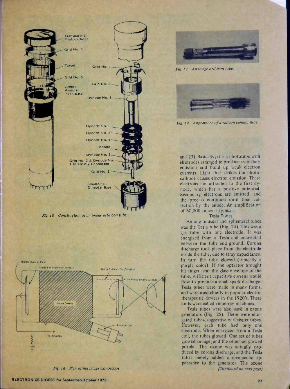
Transparent Photocathode
Grid No. 6
Target
Grid No. 5
Jumbo Annular
I' ', , ' ° % 7 -Pin Base
Grid No. 4
Grid No. 3
Dynode No. 1
Dynode No. 2
Dynode No. 3 -- Dynode No. 4-
Anode
Dynode No. 5_ Grid No. 2 & Dynode No. 1 Internally Connected
Grid No. 1
Small -Shell Diheptal Base
FYg. 18 Construction of an image orthicon tube.
Metallic Oackiog Plate
Mosaic For Secondary Emission
To Arnpllller
Gaute Cylinder For Focusing
Plane Photoyrluctnc Cathode
Electron Gun
Fig. /6 Plan of the image iconoscope.
- J"
Fig. 17 An image orthicon tube.
.......
Fig. 19 Appearance of a vidicon camera tube.
and 23). Basically, it is a phototube with electrodes arranged to produce secondary emission and build up weak electron currents. Light that strikes the photo- cathode causes electron emission. These electrons are attracted to the first dy- node, which has a positive potential. Secondary electrons are emitted, and the process continues until final col- lection by the anode. An amplification of 60,000 times is typical.
Tesla Tubes Among unusual and ephemeral tubes
was the Tesla tube (Fig. 24). This was a
gas tube with one electrode. It was energized from a Tesla coil connected between the tube and ground. Corona discharge took place from the electrode inside the tube, due to stray capacitance. In turn the tube glowed (typically a
purple color). If the operator brought his finger near the glass envelope of the tube, sufficient capacitive current would flow to produce a small spark discharge. Tesla tubes were made in many forms, and were used chiefly in popular electro - therapeutic devices in the 1920's. These units were called violet -ray machines.
Testa tubes were also used in ozone generators (Fig. 25). These were elon- gated tubes, suggestive of Geissler tubes. However, each tube had only one electrode. When energized from a Tesla coil, the tubes glowed. One set of tubes glowed orange, and the other set glowed purple. The ozone was actually pro- duced by corona discharge, and the Testa tubes merely added a spectacular ap- pearance to the generator. The ozone
(Continued on next page)
ELECTRONICS DIGEST for September/October 1972 27

HISTORY OF THE VACUUM TUBE (Continued from prcceding page)
Fig. 22 A modern photomultiplier tube.
Fig. 24 A Tesla tube.
Fig. 26 Example of a barretter, or ballast tube.
was employed as an air deodorizer and purifier and was also supposed to benefit respiratory ailments.
Ballast Tubes '"he filament current for early vacua
um tubes was controlled manually with a rheostat. However, in the later 1920's automatic current control was introduced to simplify the operation of radio re- ceivers. The first device used for current stabilization was the ballast tube, also called a barretter (Figs. 26 and 27). It consisted simply of an iron -wire spiral in an atmosphere of hydrogen. Because of the large temperature coefficient of iron, practical current stabilization re- sulted. Barretters were also designed which operated in air; however, their response time to a voltage change was slower than for hydrogen barretters.
Light shield
Incident light
Photo Courtesy Ampex Corp.
FIg. 21 A closed-circuit TV camera that uses a vidicon tube.
FOCUSING COIL
HORIZONTAL AND VERTICAL DEFLECTING COILS
GLASS FACEPLATE
0=Photocathode Mica 10=Anode shield 1-9=Dynodes
. ..o ii , .9.. :
1rv
ALIGNMENT COIL
rfr-`- : :I C
.....,:.., .' ,
.üsiiiPviFi' el:éi .
- TARGET \ TARGET CONNECTION
GRID 0 4
GRID 2
GRIDS I
CATHODE
GRID s 3
Fig. 20 Construction of a vidicon camera tube.
- I
Fig. 25 Tesla tubes in an ozone generator.
`0.40 r
- °° E 2c°0.30 s --- 1
g 0.20 ` Ov 50v l v I I v '4+ v 1;Dv Voltage across ballast tube
28
Fig. 23 Plan of a photomultiplier tube. Fig. 27 Typical E-! characteristic for a barretter.
ELECTRONICS DIGEST for September/October 1972

T.M.
. I
PICTORIAL HISTORY OF ELECTRONICS
-r3
4
r
O. M,
/ .....+ . , /1
ó, I
rI-I I
W 9XZV
This history -making picture is the first television broadcast in Chicago on March 30, 1939, which was conducted by Zenith Radio Corporation on an experimental basis. The telecast was received 18 miles from the TV transmitter. Engineers at station W9XZ V pictured here include: (from left), WLS Chief Engineer, Tommy Rowe; Howard Black; Reggie Cross; and J. E. Brown, Zenith tele- vision engineer. Rusty Gill is kneeling in front.
:11s-tr.;
In 1956 Zenith introduced this unusual method of remote control tuning - the Flash-Matic system. It operated with a flash of light to turn the set on and off and change channels. It was advertised to "shoot off long, annoying commercials while picture stays on the screen." Earlier, Zenith had introduced its "Lazy Bones" remote control system which changed TV channels in any direction utilizing a hand-held control device connected to the television set by wire. In 1957 Zenith introduced to the industry its Space command remote control tuning sys- tem utilizing high frequency sound.
4 r ,
v .
Courtesy Zenith Radio
Courtesy Zenith Radio
"HELLO AMERICA" were the first words heard in 1924 on this early Zenith radio rig
by Hiram Percy Maxim, former president of the American Radio Relay League. He is
shown in this photo published in April, 1924 by Popular Science magazine with his 1922 model 1R Zenith tuner, bottom right, and the 2M two stage amplifier, bottom left. Both sets carried the Chicago Radio Lab- oratory name - the predecessor name to Zenith Radio Corporation.
. r -.1rr-c...- . -T--i
I -
I I' ,
` 1 .. -,r I , .
(` \
hL-- - o ,1 I
7 1 NI I
4.4
ELECTRONICS DIGEST for September/October 1972 29

FROM AN ALBUM (Continued from preceding page)
I°
""~r i
' 4
l' .0":311/1
s .. ` o
1
..
1
'
11V ó
,7II
.
i!
- C
I . r , !
11. i
..1.::( 1' ". _..
n
.
I
ry . ` ... -
á
'
'ray
Photo Courtesy Bell Telephone Laboratories
TWO OF TV'S PIONEERS John R. Hefele, seated, and Frank Gray (both retired) were
two of an estimated 200 Bell Telephone Laboratories scientists, engineers, and techni-
cians whose work contributed to the success of the first U.S. demonstration of intercity television which took place 45 years ago. Many research problems involving this televi-
sion transmission and other apparatus were solved under the direction of Dr. Gray.
30 ELECTRONICS DIGEST for September/October 1972
OCEANOLOGY (Continued from page 14)
the Marine Board of the National Acad-
emy of Engineering emphasizes the
necessity for overall, integrated planning
and leadership to enable the United States to regain its position as one of the
world's foremost maritime nations, and
to ensure the "most effective utilization of all the resources of the sea for the
betterment of our country and all man-
kind." The United States has been for
many years an important maritime nation; however (the report points out), "our interest in the ocean has not been consistent: we have been both wise and, occasionally, foolish in using the sea." Today the nation faces a challenge not only to exploit more fully the rich resources of the sea, but "to do so with concern for a balance among the many demands now being placed on the marine environment. We face an unprecedented opportunity to explore the seas in greater detail than has been heretofore possible and to utilize the results of this exploration for the advancement of the quality of life on this planet."
Recommendations adopted by the Board for the establishment and opera- tion of a "truly national ocean program" are supplemented by individual panel recommendations concerning specific areas such as commerce and transporta- tion; living and nonliving resources; protection of the environment; explora- tion and surveying; construction and civil works; vehicles and platforms; navi gation; instrumentation; communication; and education and. information i dissemi- nation. Panel members point out that'a critical need for engineering -related ex- ploration and the development of ex- ploration techniques and equipment had 'been identified in their evaluation. Man's ability to work in the sea should be expanded through projects such as the Navy's Deep Submergence Rescue Vehicle program, the Sea Lab program, and man -in -sea programs. In the opinion of the Marine Board, the nation has begun to move toward an effective national marine program with the establishment of the National Oceanic and Atmospheric Administration and the Environmental, Protection Agency, but it must greatly enlarge its use of existing ocean tech- nology: it is especially important, notes the report, that "the factors governing wise application of this technology be understood at all levels of' industry, government and private life in this country and internationally, if the pre- sent and potential capabilities of the United States and the world are to be effectively mobilized."
Modular "window - nose" sub
Perry Oceanographics, Inc., a pioneer in high -visibility workboat submersibles, has begun construction of a transparent - nosed modular diver lockout submarine with mating deck chamber complex, to be used in the North Sea. The new PC -15 - a four -man, 14 -ton submarine, operational to depths of 1,200 feet, -is scheduled for completion in early 1973. The sub will be 31 feet long and will
cruise at one knot up to 15 hours - maximrlm speed at five knots. Payload, in addition to passengers, will be 2,000 pounds. Main sections of the PC -15 will be modularized and bolted together. The modular construction feature will lower assembly and maintenance cost and assure against obsolescence as new power and propulsion systems are developed in
the future. For special missions, the entire lockout section and gas sphere. may be removed and the tail section bolted ,to the front section, making a
smaller three -place observation submarine with 1,000 -pound payload capacity.
- %_
9. -
o 1 1)1
l
r
Perry Oceanographics Inc.
Artist's sketch of the new PC -15 submarine mated to its deck decompression chamber complex.
Batteries for the PC -15 will be in
twin exterior pods below the hull, giving good stability and providing nat- ural skids for landing on deck or on the bottom. Pipelines can be straddled, bring- ing the pipe within inches of the 42 - inch -diameter acrylic window. tuick- change trays will enable battery exchange and full turn -around in two hours. A
removable conning tower will have six viewports for horizontal viewing, plus an upward -looking viewport in the con- ning tower hatch. The aft, or diver compartment, will have a downward - looking viewport in the lockout hatch and four viewports for horizontal view- ing to each side. The diver lockout feature will enable two divers to be de ivered to the bottom at one atmo-
sphere, pressurized to depths of 1,200 feet with the sub's gas storage sphere, and exit from the sub to carry out work. Equipment will include gyro-
compass, auto -pilot, underwater tele-
phones, sonar and manipulators. The British firm of Vickers Oceanics
will operate the PC -15 system from their 2,800 -ton support ship, "Vickers Voyager," offering submersible services
to the burgeoning offshore industry in
the North Sea.
Radar measures wave heights
Scientists from the Naval Research Laboratory in Washington have proven ocean waves may be measured from above -the -surface platforms by making minor modifications to the Laboratory's X -band nanosecond -pulse test radar. It had been previously reported that the problem of measuring ocean wave heights from fixed -shore or bottom -mounted sensors had been solved by the use of through -the -surface sensors; however, NRL Radar Division scientists say these sensors have maintenance and reliability problems - the below -the -surface sensors, in particular, have restricted frequency response problems in bad weather. These difficulties, they say, indicate that an above -the -surface sensor, with a fre- quency response comparable to that of through -the -surface sensors, is definitely needed to report wave -height infor- mation up and down the U. S. east coast to the U. S. Army Coastal Engineering Research Institute in Washington and for general use in navy operations. As a
result of recent research, headed by G. F. Myers of the Radar Division, such a
system has been proven feasible: wave
heights have been accurately measured - looking vertically from above the sur- face - with a precision that equals that obtained when using a through -the - surface wave sensor. Myers said research using the modified NRL test radar sys- tem and stable platforms 20 to 60 feet above the surface have given excellent results, and a brief test made with a
helicopter flying 100 -feet up at 60 to 100 knots forward speed, indicates good future possibilities for use of such a
platform in wave -height measurement.
Improved echo signal processor
A new correlation echo sounder pro- cessor, the CESP-II, for bathymetric data collection has been introduced by Ray- theon Company's Ocean Systems Center,
(Continued on next page)
ELECTRONICS DIGEST for September/October 1972 31
NEWS ORBIT Oceanology (Continued)
Portsmouth, Rhode Island. An improved version of the CESP-1 introduced in 1970 the new signal processing device effectively increases acoustic output energy of standard high resolution depth sounding systems by a factor of one hundred. Its several improvements over the earlier unit include a choice of pulse lengths, smaller physical size, and more extensive use of integrated circuits.
In operation, long, wide -band, out- going transceiver pulses are stored within the logic of the unit and used as reference replicas for returning echoes. The par- ticular characteristics of transmitted sig- nals are not normally present in inter- fering noise; consequently, noise does not correlate and does not appear on the graphic recorder output display. For similar reasons, reverberations caused by various sub -bottoms do not correlate, allowing closely spaced layers to be displayed unobscured. At higher fre- quencies, the CESP-II insures that signals are clear enough to be automatically processed or digitized. At lower frequen- cies it increases penetration into the near sub -bottom. Since the equipment
provides high signal-to-noise ratio and increased noise immunity, it is partic- ularly suited to ships having noisy pro- pulsion systems.
COMMUNICATIONS
New Navy sub VLF system
During the past few years, Naval Research Laboratory scientists have been intensively studying electromag- netic wave propagation at very -low - frequency (VLF) between a newly -con- structed transmitter at North West Cape, Australia, and receiving sites located in Japan, Madagascar, Bahrain Island, Alaska and the Philippines. The North West Cape VLF transmitter broadcast signals on a schedule which permitted propa- gation data to be collected at the receiver sites on six frequencies in the VLF band over a' three-month period. The research effort, sponsored by the Naval Electronics Systems Command, has been directed toward obtaining information on VLF propagation paths that had not been previously investigated, to deter- mine which frequencies are most suitable for communication transmissions to Navy submarines. The results of the research
r 'a . nL.: o o .x
1.1/.
4 .:v
promise an important advance in Navy submarine communications and possibly a spinoff benefit for both commercial and Navy ships using the Omega navi- gational system.
Data collected from the experiments were compared with theoretical predic- tions. Some effects of multimode propa- gation were found to be evident in data taken during the nighttime period; more- over, the nighttime signals were more variable than daytime signals, which appeared to be influenced by the direc- tion that the propagation path made with the earth's magnetic field. As a
result of the investigations, the Naval Research Laboratory has now been able to give the Navy infromation on the most suitable VLF channels to use for transmissions to submarines from an existing site.
Microwave network links TV
A new microwave communications network interconnecting television sta- tions in Seattle, Yakima and Spokane, Washington, and Portland, Oregon, re- cently began service. Designed and built by Raytheon Data Systems of Norwood, Mass., the high reliability system includes
Baby steps before giant steps.
A
7.i _...._i
32 ELECTRONICS DIGEST for September/October 1972

equipment located at nine television
stations in the four cities and at 13
locations along the routes. In addition to bringing network television programs originating elsewhere into the nine sta-
tions, provision is made to send out nationwide - via reverse channels in the
microwave network - programs origi-
nating in Washington, such as spot news
and athletic events. Audio and video
signals for the three major television net-
works are beamed from mountain -top
to mountain -top in average hops of 39
miles each to cover the 436 route miles.
There are more than 100 separate trans-
mitter and receiver units along the route, each about the size of aitelephone booth; these employ Raytheon's KTR-2A
and KTR-3A transmitter receivers. To insure program continuity for the
nine TV stations and their viewers,'each of the Washington stations is equipped with three receive channels. The princi- pal channel is that station's network channel. The other two are for occasional use and for standby protection to guard against program interruption. A mini- computer serves as the electronic watch- man and trouble-shooter for the system. This data logger senses up to 128 points at each station. Each electrical check point is stored in the computer's memory.
When a trend away from peak per- formance, or a failure, is noted, an alarm is sounded and engineers can correct the problem before it causes a serious interruption ín the television signal. The minicomputer not only helps mainten- ance engineers anticipate trouble, it also helps direct their attention to the trouble spot, thereby reducing maintenance time. The watchdog system also serves as an intrusion alarm: should someone climb a mountain top to tamper with the signal - or any of a score of similar occurrences, engineers are warned of this immediately.
The system - controlled from Port- land, Oregon, at the Television Operating Center - is an addition to the more than 13,000 route miles of microwave links operated by Tele -Communications, Inc., of Denver.
Bell's no. 4 ESS switching system
Bell Labs is developing a new elec- tronic switching system for the Bell
System that will handle about 350,000 long-distance calls an hour - three times as many as the electromechanical toll system now being used. The first in-
stallation of the system, known as No. 4
h. Photo Courtesy Bell Labs
Paul Wiley, member of Bell Labs Technical Staff, removes circuit' pack in No. 4 ESS switching system scheduled for service by the end of 1975.
ESS, is slated to begin service in Chicago by early 1976. No. 4 ESS will replace electromechanical parts with solid-state components to switch digital signals directly - for the first time in the Bell System. The new system will be capable of switching the digital bit stream from transmission lines used in Ti and T2 carrier systems. Switching digital signals directly reduces the need for conversion of such signals to analog form. In ad- dition, No. 4 ESS is expected to take up less floor space, primarily due to the use of small, reliable, integrated circuits which contain many electronic com- ponents on a tiny silicon chip.
. Today, getting brilliant sound from four sepárate speakers is easy,
because we started out getting it from one.
And engineering 80 watts of driving power into a
five function, solid state, pushbutton power unit calls upon many of the things we learned working with vacuum tubes.
But with everything changing, some things haven't.
We still design, engineer, build, warranty and service everything we sell. Just as we have for over 50 years..
0
And we still believe that a big price tag is not the best way to convince people they're buying quality' sound equipment.
Basically, we feel if you're smart enough to know you don't have to pay more than $230 to get a big -sounding stereo AM/FM radio, phonograph
and 8 -track cartridge. tape player, you should be smart enough to buy an Arvin.
Mnn
Arvin Industries, Inc., Columbus, Indiana 47201. There are 10 different Arvin compact stereo systems. This one, the 80L88.18, has full stereo phonograph, 8 track cartridge tape player and FM/AM/FM stereo radio; with
4 air suspension speakers, full slide controls and blackout panels.
ELECTRONICS DIGEST for September/October 1972 33
1

NEWS ORBIT (Continued)
SPACE RESEARCH
Long -duration spaceflight
A recent report, prepared for NASA by the Space Science Board of the National Academy of Sciences - Nation- al Research Council, stresses that in planning for long -duration spaceflight, the spacecraft will have to be viewed as a "microsociety in a miniworld," with more concern for the social needs of individual crew members; attention will have to be turned from the spacecraft itself - which has logically absorbed all attention in the first decade of space research - to the special human require- ments of the men who will live in it for periods of up to two years at space stations and laboratories. Despite the success of the manned space program to date, the report states that scientists cannot ensure that man will be able to tolerate longer flights: a great deal more must be known about a whole range of physiological and psychological factors - from deconditioning of body systems during long flight, to possible impair- ment of mental performance due to lengthy isolation and confinement. Re- search is critically needed to determine the effects of confinement, isolation and sensory deprivation on cognitive func- tioning; retention of skills and mental alertness; sleep and work -rest cycles; and on interaction" among crew members. "While questions regarding the long-term physiological effects of weightlessness remain unanswered," the report states, "consideration must also be given to the maintenance of health over extended periods of time without access to elab- orate medical facilities, to provision for adequate training to handle extremely complex tasks, and to crew selection that takes into account ability to tolerate long-term isolation from the outside world except for communication with ground control."
The report recommends that first priority in research be given to deter- mining the course of physical decondi- tioning over a two-year period. Weight- lessness and restricted activity in the spacecraft can lead to general decondi- tioning and specifically to decondition- ing of the cardiovascular, musculo- skeletal, metabolic and neuroendocrine systems. There was evidence of decondi- tioning with no ill effects during the longer Gemini and Apollo missions, but little is known about whether decondi- tioning would progress with length of
stay in space, or whether the human body would adapt. More study is also needed on another potential hazard in deep space - high-energy heavy cosmic rays, known as high -Z particles. Radia- tion from these particles may adversely affect nondividing cells in the central nervous sytem.
In view of the changing demands of long -duration flight, the report further recommends that the space "mission" be redefined to include the entire period from designation of the crew through postflight debriefing and flight reports. The report advocates the inclusion of the flight crew in mission tasks from the very beginning of preparation: "in- dividuals selected for the astronaut pro- gram must be integrated into the total effort in such a way that they are willing to make a single flight the culmination of a career."
New hi -temp strain gage
A new high -temperature capacitance strain gage that can measure structural stresses imposed at temperatures as high as 2000 degrees Fahrenheit has been developed - in a five-year program - by Hughes Aircraft Company for use in the development and qualification testing of aircraft, missiles and space vehicles during simulation of external loads and temperatures in the flight environment. The 'h -inch -long gage is a rhombic frame with a capacitor element composed of Iconel plates and mica dielectric insula- tors. The sensor is incorporated in a TD nickel chrome frame with mica insula- tors to transmit stresses in the base material as it is strained under aero- dynamic or temperature loads into changes in capacitance due to altera- tions in the distance between the steel plates; these capacitance changes are the measure of strain being endured by any test vehicle.
More than 20 configurations were studied for attachment of the strain sensor to various structural materials. Three techniques for attachment to the test vehicle were investigated: welding, flame spraying and bonding. Flame spray- ing was considered the best means for the strongest attachment at 2000 degrees Fahrenheit, although welding was pre- ferred because it was the easiest to perform.
Temperatures associated with present- day aircraft, space and missile vehicles are in the 1000 to 1500 -degree range but this region is expected to increase to 3500 to 4000 degrees during the late 1970's; laboratory tests have demon- strated that the new gage provides a
positive and accurate Ineans of iiieasui ing structural stress at temperatures up to 1750 degrees Fahrenheit, and under specific test conditions data can be obtained as high as 2000 degrees.
More than 100 gages have been bought by the Department of Defense and NASA for test purposes in such programs as the space shuttle and ad- ditional quantities have been purchased by several firms engaged in aircraft and missile programs.
Logistics support for NASA
Raytheon Service Company of Bur- lington, Massachusetts, was recently selected by the National Aeronautics and Space Administration for $42.5 million contract negotiations - over a three-year period - to provide continuous logistics support for tracking, data acquisition and communications facilities for the NASA Space Flight Space Tracking Data Network (STDN), managed by the God- dard Space Flight Center. Under the provisions of the contract, Raytheon will provide logistic support services to the Goddard Space Flight Center project control centers; communications switch- ing centers; and network tracking stations, training centers, test facilities, instrumented aircraft and calibration and repair facilities. Services will consist of all material, personnel, utilities, auto- matic data processing, system modifica- tion and program modification required to manage and operate a depot near Baltimore, Maryland, in support of the equipment and facilities of a world-wide network.
ECOLOGY
NYINJ Atlantic dump site study
The New York City dump site off Sandy Hook, N. J., was one of the places visited by deep -diving submersibles oper- ating in the. Atlantic Ocean in recent summer months in a program under the direction of the Manned Undersea Science & Technology Office of the National Oceanic and Atmospheric Administra- tion. The intensive undersea study, which began June 19, involves the movement of sediments along the seafloor in an area called the New York Bight. West- inghouse Electric's Deepstar 2000 sub- mersible and the Navy's submersible, Alvin, operated by Woods -Hole Ocean- ographic Institution, were used for on -site examination of the seafloor. The surface
34 ELECTRONICS DIGEST for September/October 1972

ships Lulu, State Wave and Venture
supported the submersibles while mak-
ing seismic profiles and side -scan sonar
recordings. Exploration of the ocean
floor stretched from the New York
city dump site off Sandy Hook out to the head of the Hudson Canyon - a
deep valley in the continental shelf and
slope - and down to the head of the
Wilmington Canyon off Atlantic City, N.J. Some scientists believe that canyons
such as these may serve as "pipelines" for the movement of sediment and
sinkable pollutants from the continental shelf to the deep ocean; the first phase
of the project focused on the dynamic processes active in these canyons to
determine whether, in fact, sediment is
transported along the canyons into the deep ocean and, if so, at what rates.
The second phase of the project - from July 4 through July 13 - dealt with sediment transport on the New York and New Jersey portions of the
continental shelf, between the Hudson and Wilmington Canyons. In the first series of dives in this study, undertaken in October 1971, evidence was found that storm currents do move seafloor sediments about and cause slow but un- mistakeable changes in the topography of the shelf. These findings challenged one scientific view which held that little has happened to the continental shelf since it was flooded after the ice age. In the second phase, Westinghouse's Deepstar 2000 was used to look for evidence of sediment transport along the bottom of the shelf, such as current ripples and areas of bare rock that might have been swept clear of sand and sediment.
In addition to the immediate studies made during the dives, scientists em- placed various kinds of sensors or tracers that will be read out during follow-up dives in September. At various locations along both the Iludson Canyon and the adjacent continental shelf, Deepstar 2000 scientists set out current meters on the bottom. Whenever the currents exceed about 20 cm/sec, the meters will record their strength and duration. The Navy's Alvin also set out bottom stakes in the Iludson Canyon, to measure sediment slides down the canyon slope. These stakes will again be checked in
September and the amount of move- ment recorded. From Deepstar 2000, soluble blocks of dyed sand (about the size of loaves of bread) were placed on the bottom of the continental shelf, with different colored dyes for different sized sand grains. These will be photographed in September to show sediment trans- port during the intervening three months.
New effluents measurer
The Region VIII Environmental Pro-
tection Agency in Denver has begun using a new Varian Techtron Model
635 UV-Vís Spectrophotometer for water and waste effluent analyses across the six -state region, using the instrument in a "mobile lab" trailer -type van. The Model 635 is one of a new line of scanning spectrophotometers suitable for economical studies of waterway effluents and pollutants in lakes, reservoirs and other natural waters. According to John Tilstra - chief chemist for the laboratory services section of the EPA - the new spectrophotometer "has exceeded per- formance expectations" and has demon- strated a high degree of versatility: "we are required to measure unknown and widely variable concentrations of diverse constituents in everything from sewage digester sludges to mine wastes to natural waters." The principal parameters rou-
tinely measured on the Model 635 are: orthophosphates, ammonia, nitrite nitrogen, nitrate nitrogen, boron, sele-
nium and arsenic.
NATIONAL DEFENSE
Navy automatic tracking system
Scientists at the Naval Research Lab-
oratory (NRL) in Washington have de-
veloped a systematic approach for the design of a digital automatic tracking antenna system. The new NRL system, which has been developed around pre-
sent modes of operation, advances the main design criteria of accuracy, reli-
ability, ease of maintenance and mini- mum cost. An optimum technique to convert from a manual tracking antenna system to an autotracking system is
made possible by the NRL-developed special-purpose system controller, auto- matic control unit (ACU- I) and by the commercial availability of low-cost and accurate digital-to-synchro (D/S) con- verters.
The NRL-proposed system is designed to relieve the human operator of menial tasks, performed manually in current systems, while taking maximum advan- tage of his ability to make decisions. The operator prepares a punched -paper tape using an off-line computer, veri- fying the tape to assure accuracy. In- formation for two antennas is stored on the tape, and the tape is read by the ACU-I which reformats and transmits the digital data at specific time in-
tervals to a D/S converter for each
antenna. The autotracking process is
initiated at a preset time and auto-
matically stops at the completion of the specific task.
Improved Hawk Missile tests
The first Theater Readiness Monitor- ing Facility (TRMF) for testing Improved Hawk missiles has been delivered to the U. S. Army by Raytheon Company. The TRMF gives the Army a computer- ized test capability for assessing the status of deployed Improved Hawk mis-
siles on a sample basis. By sample testing under controlled environmental condi- tions, known variables are eliminated, thereby providing an accurate system trend prediction for the Certified Round Hawk missile in terms of the effects of handling, transportation, storage and aging.
Improved Hawk, which was started in
1964 to incorporate the latest advances in technology, now features a com- pletely redesigned missile with new guidance package, larger warhead and improved motor propellant. Higher re-
liability is made possible by the use of solid state components throughout. The maintenance burden to soldiers in the field is less because the missile goes directly from the production line to the launcher as a "Certified Round"; no maintenance or test is required by the Army in the field.
RAPID TRANSIT RESEARCH
Electric power "city"
An electric power supply and dis-
tribution system equivalent to that for a
city of 20,000 persons will be designed by the Jackson & Moreland Division of United Engineers & Constructors Inc. for the U. S. Department of Trans- portation's High Speed Ground Test Center at Pueblo, Colorado. Employing only a few hundred persons, the new test center "city" will have test tracks, facilities and available electric power for full scale research in high speed ground transportation systems. In planning or under construction at the 50 -square -mile site are an 80 -mile -per -hour conventional rapid transit test track; a I20 -mile -per - hour conventional railroad track; a test track for vehicles with linear induction motors; and a guideway for tracked air cushion vehicles that can hit speeds up to 300 miles per hour. In a related
(Continued on next page)
ELECTRONICS DIGEST for September/October 1972 35
J
NEWS ORBIT Rapid Transit (Continued)
assignment, Jackson & Moreland are also designing the Wheel/Rail Dynamics Facility I est and Test Support Building to be constructed at Pueblo for full scale testing of rail -borne vehicles simu- lating the dynamics of speeds up to 300 miles per hour.
EDUCATION
MIT practicing engineer program
The M.I.T. Center for Advanced Engineering Study is now accepting applications for the Practicing Engineer Advanced Study Program - an intensive, in -residence program of continuing ed- ucation for experienced engineers, ap- plied scientists, technical managers and educators, individually tailored to the background and objectives of each par- ticipant. The Program will combine classroom study, seminars, guided in- dependent study and research. All the resources for education and research throughout M.I.T. are available to the Fellows of the Center. The Program is divided into segments which coincide with the M.I.T. summer, fall and spring terms. Participants may start at the beginning of a term or at the beginning of special review subjects offered during the summer. For more information and application forms, write to: Practicing Engineer Advanced Study Program, Center for Advanced Engineering Study, Room 9-215B, M.I.T., Cambridge,' Mass. 02139.
New B.A.'s in computer science
Advanced degrees in four related science areas - electrical engineering, mathematics, computer engineering and computer science - have been offered for some time by the University of Illinois, Urbana/Champaign; now, how- ever, the school becomes the first to of- fer a full spectrum of course work in
computer engineering and computer science at undergraduate as well as graduate levels. A B.A. degree in com- puter engineering was added to the university's curriculum a year ago and undergraduate opportunities are now complete with the addition of the B.A. in computer science.
Computer engineers specialize in the design and construction of computers; computer scientists in their operation and application. With emphasis in dif- ferent areas, the two curricula involve
courses in the engineering college's elec- trical engineering department and the U. of I. Graduate College's computer science department.
HONORS
Navy commends data -design labs Data -Design Laboratories was recently
presented with a special commendation flag from the U.S. Navy for its "out- standing contribution" to the Poseidon missile program and its "unprecedented excellence" in technical and training support for the program. Clayton E. Evans, engineering manager for the Navy's Strategic Systems Project Office - the nation's Polaris/Poseidon missile agency - presented the flag to Robert Wood, Data -Design Laboratories' vice- president and manager' of development for this diversified corporation with more than a decade of experience in research, development, design and pro- duction of defense electronics systems.
The Navy stated in its commendation that the recent deployment of the U.S.S. James Madison with the Poseidon weap- on system aboard was a "most signifi- cant milestone" in the defense of the United States and that Data -Design Lab- oratories' contribution to the program "in establishing training requirements, personnel performance criteria, and test- ing methods," as well as a "high degree of management, technical ability and competence," greatly contributed to the Navy's ability to operate and main- tain the nationally -vital Polaris/Poseidon weapons system.
BOOKS
New Archer transistor guide
The new Archer Transistor Substitu- tion Guide from Radio Shack Electronics lists 15,000 commercial transistor types which, in most cases, may be directly replaced by one of 29 Archer transistors. Detailed specifications and electrical characteristics for each of the 29 tran- sistors are given in the booklet. 24 of these transistors are custom-made for Radio Shack by Texas Instruments, Inc., and five are imported from a top manufacturer. The 96 -page booklet also contains useful information on the care, handling and testing of transistors and important suggestions on their use and replacement. The Archer Transistor Sub- stitution Guide is priced at $1.00 and is
available at all Radio Shack stores. Copies of the book are available at no cost to educators in high schools, colleges, technical and vocational schools. These may be requested by writing to Radio Shack, Dept. EP -1, 2617 W. Seventh St., Fort Worth, 1 exas 76107, on your school letterhead. Please men- tion Llectronics Digest.
Using car tune- up testers
"Using Electronic Testers for Auto- motive Tune -Up," by Albert Wanninger (TAB BOOK No. 604, Cloth: $7.95 - Paper: $4.95), is an all -in -one, profusely illustrated manual providing complete information and operating instructions for all commonly -available electronic devices used for auto tune-up. Wanninger starts with simple voltage and continuity checks, progresses through more involved procedures employing oscilloscopes and specialized testers, and ends with a complete automotive tune-up on console - type analyzers. Contents: Voltmeter and Ohmeter Tests - Battery Charger Tester - Charging System Analyzers - Tacho- meters and Dwell Meters - Timing Lights - Ignition Advance Testers - Ignition Testers - Ignition Oscilloscopes - Electronic Compression Testers - Vacuum Gauges - Exhaust Gas Ana- lyzers - Specialized Testers and Diag- nostic Equipment - Glossary - Index. The manual can be ordered through your book store, or direct from Tab Books, Blue Ridge Summit, Pa. 17214.
MILESTONES
I 1
J
' .., 2\, , . .
CELEBRATING WESTERN RADIO'S 40 YEARS in the electronic distribution business are (left to right) sales representatives Paul Marquez, Art Fox and John Tunnel!, and sales manager Jim Reynolds. Art Effron, district sales manager for Genera! Electric's Electronic Components Sales Department, presents the San Diego firm with a silver coin clock commemorating its four decades in the electronics field.
36 ELECTRONICS DIGEST for September/October 1972

SUBSCRIBER SERVICE
Only the sound is heavy
v
IO S S HV-1 stereophone Until now a lightweight stereophone meant a lightweight sound. But not any more. Because Koss has developed a
revolutionary new micro/weight High Velocity Stereophone that sounds like a
heavyweight. And that's an achievement no music lover will take lightly. For more
information on the new Koss HV-1 and the full line of Koss Stereophones, write for our free color catalog, c/o Virginia Lamm, Dept. M-172. Or hear the Sound of Koss at your Hi -Fi Dealer. At $39.95, the price of the new HV-1 is light, too.
from the people who invented Stereophones
KOSS CORPORATION 4129 N. Port Washington Ave.. Milwaukee. Wis. 53212 Koss S.r.I., Via dei Valtorta. 21 20127, Milan. Italy
APPOINTMENTS
Radio Shack names B. H. Hunter exec v -p
Bennett 11. Hunter has been named to the position of executive vice presi- dent of Radio Shack, a Tandy Corpora- tion Company, by Charles D. Tandy, chairman.
llunter, 54, who had been vice presi- dent and regional manager of Radio Shack's central region, now assumes responsibility for the establishment and execution of operating policies and pro- cedures for the company's more than 1500 retail stores in all 50 states and Canada.
In announcing the appointment, Charles Tandy stated, "Bennett I lunter is one of the outstanding men in our organization who has contributed sub- stantially to our success and to the devel- opment of other men of ability."
Hunter succeeds G. R. Nugent who has joined the executive group of Tandy Corporation.
I lun ter joined the Tandy organization in 1960 as a manager trainee, served as a
store manager on the west coast, and later became district manager in San Francisco. In 1966 he transferred to the Radio Shack division as a metro man -
-
Bennett H. Hunter
ager in Memphis, Tennessee. Ile became a district manager in 1968 and was appointed vice president and regional manager in January, 1971.
Originally from North Carolina, Ilunter is a graduate of the University of North Carolina and a veteran of World War II. I le and his wife Doris now live in Iort Worth, Texas with their children, Barbara Scott, 24, Bennett, Jr., 14, and Doris Marie, 12.
,-AFFIX LABEL r-, --I o
Please include an address label when writing about
your subscription to help us serve you promptly.
CHANGE OF ADDRESS:
Please let us know you
are moving at least ó I four to six weeks in
M advance. Affix maga
1 I zine address label in
space to the right and
o print new address be -
ó I low. If you have a f question about your subscription, attach address label to your letter.
TO SUBSCRIBE:
oI Check boxes below.
v [.]New Renewal
cu
Ai $250
o
I I
l.-MOO di"»`._J All other
sl Per Year (6 Issues)
U. S., Canada & Mexico
Countries $4.00
' Electronics Digest®\ ADVERTISING/EDITORIAL OFFICES
11024 Currie Street, Ft. Worth, Texas 76107
NAME
ADDRESS
CITY STATE ZIP
BACK ISSUES
AVAILABLE Use this coupon to order back issues of
Electronics Digest We have a limited supply of back issues that can be ordered on a first -come, firstserved basis. Just fill in the coupon below, enclose your remittance in the amount of 75a for each copy ordered.
Please send the following back issues of
Electronics Digeat® 1024 Currie Street Fort Worth, Texas 76107
am enclosing ...., .... ... to cover cost of
the magazine, shipping end handling.
Month ........_ Year
Month Year
Month Year
Name
Address
city ,...
State lip
tlttll MI Payment must be enclosed with order
ELECTRONICS DIGEST for September/October 1972 37

ElHtr^"ics> SCIENCE PROJECT
Transistors require proper sources of voltage to keep currents at a safe value. Output energy must be coupled into some form of load in order to appear at the correct circuit point. Other com- ponents must be chosen so power is efficiently transferred from one section of the circuit to another.
An effective way to gain insight into over-all transistor operation is the con- struction of a simple one -transistor am- plifier. As it is adjusted, varied, and measured, the underlying transistor action may be observed. As stated earlier, this is its ability to utilize a small current flowing between base and emitter to control a much larger flow between emitter and collector. Such an amplifier and its construction details are described in this chapter. As the idea of amplification becomes clear, it is an easy matter to modify the circuit so it performs as an oscillator; an important application evolving from the transistor's inherent ability to amplify.
COMMON -EMITTER AMPLIFIER The example chosen to demonstrate
amplification represents the most widely used circuit configuration; the common emitter. This is shown in the schematic of Fig. 1. The name is derived from the fact that the emitter is common to both the input (the section of the circuit that receives a signal) and output (the area where amplified energy appears). The transistor itself is a PNP type 2N322, which is typical of the numerous gen- eral-purpose units that are popular among experimenters.
To set up a working demonstration, follow the construction details set forth in Fig. 2 and the following Parts List.
PARTS LIST R1 -4.7K 42 -watt resistor (962 B 1800 $.12) R2 -500K potentiometer with switch (961
B 1714 $1.50) R3 -1K 42 -watt resistor (962 B 1800 $.12) X1 -2N322 transistor ($.64) B1 -9 -volt transistor -type battery (23-464
$.35) SW1-Switch for R2 (961 B 5400 $.99) Misc.-Perforated board; circuit push -in ter-
minals (270-1394 $1.59 per 100); bat- tery clips (270-325 $.60/pkg. of 5)
The chassis is simply a piece of per- forated board to which various circuit components are mounted. The leads supported by small metal clips, terminal strips or simply threaded through board
RI
4.7K
R2
SOOK
Fig. I . Common -emitter
o
Basic Transistor Operation
r .
X1 2N322
E\
SMALL CURRENT FLOW\
J
. t__J
LARGE
CURRENT FLOW
BI
9V
amplifier circuit.
...... y
P
1
,,1,41111?t
Fig. 2. Pictorial drawing of common -emitter amplifier.
holes. The potentiometer control is
bracket -mounted in one corner by means of a strip of scrap metal. Two con- nections in the circuit are purposely incomplete. They provide test points for connecting meter leads to measure cur- rent flow at the input and output sides of the transistor. Notice that points 1
and 2 allow current readings to be taken at the base of the transistor; 3 and 4
1K
are in the collector circuit Whenever the meter is connected to measure cur- rent at one set of test points, the other set must be shorted. This is done with a
small jumper made by attaching alligator clips to both ends of a piece of hookup wire. The jumper may then be shifted back and forth between collector and base, as is the meter.
(Continued on next page)
38 Reprinted by permission from "Understanding Transistors and Transistor Projects." Copyright 1968 and 1971 by ELECTRONICS DIGEST for September/October 1972 Allied Radio Shack Fort worth, TX 76107

BASIC TRANSISTOR OPERATION (Continued)
INPUT
BIAS CURRENT P N P
OUT PUT
CURRENT
BATTERY A BATTERY B
OUT PUT
Fig. 3 - Common -base amplifier circuit.
Caution: Remember that the meter range switch must be changed to pre-
vent slamming the needle. A recom-
mended procedure is to start with the
meter on the highest range and then switch to a lower range that provides the best indication.
The meter is a VOM (volt-ohm- milliammeter). It is the most valuable single instrument used by the electronic hobbyist to analyze, adjust and trouble- shoot home -built circuits. While a rela-
tively inexpensive VOM is adequate for checking many transistor circuits. the sensitive 20,000 ohms -per -volt model should be considered if the hobbyist contemplates any significant amount of experimentation.
The basic layout of the amplifier contains various elements already de- scribed in terms of theory, plus new components which make it a practical circuit. Notice the position of the 9 -volt battery in the schematic. The negative terminal can apply voltage to the base through resistor R I , potentiometer R2, and test points I and 2. The emitter connects to the positive battery ter- minal through on -off switch SWI. Thus, the forward bias requirements of a
PNP transistor are met. The collector - emitter circuit receives correct bias vol- tage from the battery. The purpose of the three resistors should become ap- parent as the circuit is placed into operation. The over-all object is to discover if a small input current to the base circuit will result in a large current flow in the collector circuit. The action may be followed by actually performing the following steps, or tracing out the schematic in Fig. I .
EXPERIMENT TESTS
First, the meter is set to read at least 100 microamperes, and its negative probe is clipped to test point I. The positive probe goes to point 2. Test points .3 and 4 arc connected with the jumper. Turn on the power by rotating potentiometer R2 and observe the cur- rent indicated by the meter. It should he possible to vary the reading from
PNP
I N PUT
Fig. 4 - Common -collector amplifier circuit.
nearly zero up to 90 or 100 micro- amperes. Note the action of the potentio- meter; its slider determines how much resistance, and thus voltage drop, occurs between the base and negative battery terminal. The lower the resistance, the greater the voltage difference there is
between base and emitter. As forward bias between these elements is increased, the current in the base -emitter circuit increases. The fixed resistor, R1, serves as a current -limiting device. It keeps a
small amount of resistance between base and battery at all times. Otherwise, full battery voltage at the base might cause a current flow beyond the maxi- mum rating of the transistor.
Base currents may now be compared with those flowing in the collector. As a
starting point, adjust the potentiometer so 20 microamperes is indicated on the meter. Don't disturb the potentiometer and transfer the meter leads to test points 3 and 4 - positive probe to 3 and negative to 4. Shift jumper to points 1
and 2. Collector current should be on the order of .5 milliampere (500 micro- amperes). This is only an approximate figure, since wide variations between transistors are normal.
One highly significant conclusion may be drawn from these simple steps: If a base current of 20 microamperes causes the collector to conduct .5 mil- liampere, then the collector current is
approximately 25 times greater than that flowing in the base. This represents the DC current gain of the transistor, more precisely termed IX' beta, and is
a measure of the transistor's ability to amplify. As mentioned in an earlier chapter, the original source of current is the battery. The arrows in the sche- matic of Fig. I point out the principal directions taken by electrons irom the battery.
I he demonstration circuit can reveal another major characteristic of the am- plifier. This is an ability to recreate the shape of the current being amplified. To prove this for yourself, restore the hoard to its original setup by returning
the jumper to test points 3 and 4 and the
major leads to 1 and 2. Adjust the potentiometer for a reading of 40 micro- amperes in the base circuit, exactly double that of the earlier step.. If col-
lector current is now measured it will
be found to be conducting about 1
milliampere, also double the previous value. A third check can be made by
adjusting R2 for a base current of 80 microamperes. In this case, collector current should rise to 2 milliamperes. Thus, it may be seen that the 2N107 not only amplifies by a factor of ap-
proximately 25, but does this in a linear manner. This is true over a range of input currents which fall within the transistor's normal ratings. Linearity in
the transistor in many applications is
important. For example, if small voice
currents from a microphone are to be
amplified, the large output currents from the transistor should bear the same basic shape as the input, or distortion will result.
With the existing setup, a charac- teristic peculiar to the common -emitter amplifier can be examined. Although a
signal passing through a transistor wired in this manner is amplified faithfully, the output is actually a mirror image of the input. A process of phase reversal occurs. It is easy to demonstrate. Both test points on the board are jumpered, one with the clip lead already made up, the other with a short piece of hare hookup wire. The VOM is adjusted to read 9 volts DC and the probes con- nected; positive to the positive battery terminal and negative to the transistor collector. When the power is turned on, the meter reads the volW,e between emitter and collector approximately 9 volts. Rut, as the potentiometer is
rotated to increase base current, note that collector voltage proceeds to drop. It reaches nearly /ero when time potentio meter is at full clockwise
Thus, it may he seen tint an increase of negative voltage applied to the base causes a corresponding decrease of nega
/(',,Willed o1 NI' i I page')
ELECTRONICS DIGEST for September/October 1972 39

BASIC TRANSISTOR OPERATION (Continued)
tive voltage at the collector. [n effect, the collector is shifting to an opposite, or in a more positive, direction from that of the base. The net effect is that a negative -going signal applied to a com- mon -emitter amplifier creates a positive - going signal at the output.
COMMON -BASE AMPLIFIER This arrangement is encountered less
often than the common emitter, but finds some application in oscillator cir- cuits. There is no phase change in a
signal as it is transferred from input to output of a common -base amplifier, and current gain is always less than one. This last statement does not mean that the transistor fails to amplify. Although current may be greater at the input, voltage changes are greater at the out- put than at the input.
The basic action of the common -base connection is shown in Fig. 3. Note that the base is common to both emitter and collector circuits. Battery A supplies the necessary current to bias the emitter in the forward direction. The other voltage source, Battery B, provides the reverse bias required by the collector. Bias current, indicated by the light arrows, is a relatively small circulation between emitter and base. Tracing the larger circulation of collector current, we find that it also flows in the input circuit, traveling from collector, through the two batteries, to the emitter. Thus, it may be seen that output current also flows in the input. If bias current at the base were made to increase, over-all current would also rise. The load resistor (R) in the collector circuit displays an increasing voltage drop as added current flows through it.
COMMON -COLLECTOR AMPLIFIER This is the final arrangement in the
three basic amplifier connections. The input signal (see Fig. 3) is applied be- tween base and collector. As the signal grows increasingly negative, current flow in the output (emitter -collector) also rises. The direction of the signal at the output is the same as for the input which accounts for the lack of phase reversal in the common -collector am- plifier.
IMPEDANCE This term is used often in conjunc-
tion with transistor amplifiers. It is a
relationship between voltage and cur- rent, as determined by the amount of opposition presented to current flow. In general, where relatively large cur- rents flow, impedance is low. The value is measured in ohms and is increasingly significant when signals must be trans-
ferred in and out of the transistor amplifier at maximum efficiency. Op- timum power transfer occurs when the signal source has the same impedance as the input impedance of the transistor. Of equal importance is the impedance of the load, which should extract max- imum energy from the transistor. It, too, must display an impedance as
nearly equal to the transistor's output impedance as possible.
This largely accounts for the appli- cation of the three different amplifier arrangements just described. In the com- mon -emitter circuit, input impedance is
characteristically low, on the order of a
few hundred ohms. The reason is that the base is biased in a forward direction and the opposition, or resistance, to cur- rent flow is also low. Output impedance is considered to be medium, a few thousand (Aims; the collector circuit is reverse -biased and exercises greater op- position.
The other amplifier arrangements, as a consequence of their current flows, display different characteristic imped- ances. In the common -base, for example, it is extremely low at the input, ex- tremely high at the output. The con- dition is exactly reversed in the common collector amplifier - very high input impedance, very low output impedance. Through choice of amplifier arrange- ment, the designer can choose a con- figuration which best serves the needs of a particular circuit. It must be realized, however, that there is a limitation in- herent in this process since voltage and current amplification are also variable factors. This helps to explain the popu- larity of the common -emitter amplifier; it yields relatively high gain when con- sidered in terms of voltage, current, or power.
AC AMPLIFIERS For the sake of simplicity, the trans-
istor has been described here as a device capable of amplifying a DC, or direct
INPUT SIGNAL
PNP
current, signal. In practice, however, AC amplification is far more common- place. The input signal often takes the form of a rapidly changing current flow which alternates directions pro- viding positive and negative values. Fig. 5 illustrates a typical AC amplifier. Note that it is similar to the earlier version of the common -emitter PNP amplifier, except for the addition of capacitors C I and C2.
Resistor RI acts as the base bias resistor. Its value is selected so a nominal amount of current results in the col- lector and through load resistor R2. Collector current at rest is shown by the dotted line marked "Static Current." Up to this point, we have a basic DC amplifier. The current through it is steady and unchanging. The application of an input AC signal alters this con- dition. This is shown as a varying cur- rent shifting between plus and minus at the left. As the AC signal reaches the base (through capacitor C l which offers no opposition to AC), it will oppose or aid base bias current. When the positive part of the AC cycle is applied, it cancels some of the negative -going bias and current in the collector circuit drops. The opposite effect occurs, when the negative -going part of the cycle adds to the base bias; collector current in- creases. Therefore, collector current is made to vary in strength around its static, or resting, value. Notice that output current is an accurate reproduc- tion of the AC input, though much larger in amplitude, or strength. There is the phase change, which typifies the common -emitter amplifier, but it is of little concern in this application.
The function of the two capacitors in the circuit is to preserve the operating biases applied to the transistor by the battery. Capacitors have the ability to block steady DC, while presenting little opposition to a varying (AC) signal; thus the original biases cannot be lost through the input and output pathways.
(Continued on next page)
AMPLIFIED SIGNAL
/ 0
STATIC COLLECTOR
CURRENT
1 DOTTED LINE)
Cp Q OUTPUT SIGNAL 1=. f
Fig. 5 - Basic AC amplifier circuit.
40 ELECTRONICS DIGEST for September/October 1972
BASIC TRANSISTOR OPERATION (Continued)
An examination of the amplified out- put reveals an interesting phenomenon. Notice that the waveform of the col-
lector signal lies completely above the zero current line. Although it is a re-
creation of the input, it has been changed from AC to pulsating DC. This
occurs since the signal ís, in effect, a
changing of static collector current which
can only flow through the transistor collector -emitter circuit in one direc-
tion. The output capacitor passes pul-
sating DC in much the same manner as
the original AC input. DC is blocked and the zero reference is preserved.
The next section presents a des-
cription of how you can construct a
practical amplifier to illustrate these principles just discussed.
AC AMPLIFIER EXPERIMENT
The common -emitter circuit in Fig.
1 is readily converted to a demonstra- tion model for AC amplification. The additional items needed are:
(1.) a .1-mfd tubular capacitor (2.) one earphone, 1,000 -ohm mag- netic type (3.) additional hookup wire
Fig. 6 - Practical AC amplifier circuit.
The altered circuit is shown in Fig. 6. The AC signal to be amplified can be obtained from the speaker leads of a radio (or phonograph). Connect two lengths of hookup wire to the terminals of the speaker and bring them near the circuit board. As a preliminary test, connect the earphone to the ends of these leads and listen to the signal. The radio volume control should be left at a
low level throughout these steps, pro- viding just enough volume to be barely audible in the earphone. If you find it difficult to differentiate between the sound from the radio speaker and that from the earphone, disconnect one speaker lead, being certain that it is
rejoined to the piece of hookup wire.
Next, wire the earphone into the collector circuit of the transistor to serve as a load. (The 1,000 -ohm resistor used for the earlier demonstration should be removed completely during this step.)
Set the VOM to read approximately 1 milliampere of current and connect its probes to test points 3 and 4. (Observe the polarity given in the schematic.) Once the on -off switch is turned on, the potentiometer which controls base bias is rotated for a collector current of exactly 1 milliampere. This amount of current establishes a Class -A mode of operation for the transistor.
Now the signal may be applied to the input. Note that this is introduced through the .1-mfd blocking capacitor fastened to the base of X1. The other input connection is the piece of hookup wire to the emitter.
Listen in the headphone - the volume of the program should sound consid- erably louder than when it was obtained directly from the radio. If there is
distortion, lower the volume control setting on the radio to avoid overloading the transistor input. (This is best ac-
complished while listening to a voice program.)
In addition to the concept of am- plification, the circuit demonstrates other characteristics. Note that the meter needle, which is indicating collector current, remains fixed at 1 milliampere while the program is being amplified. Although the input AC signal is causing a great fluctuation in collector current, this occurs above and below the 1 -ma static collector value. The needle cannot move at the rapid audio rate of the pro- gram and therefore settles down at the average 1 -ma value. This current level remains the same no matter what the level of input signal, as determined by the radio volume control setting. It is, of course, possible to overload the transistor by increasing the input beyond the current -handling ability of the base circuit.
EDITOR'S NUPE: The foregoing article was reprinted in purl from an outstanding little handbook entitled Understanding Transistors and Transistor Protects. It provides a practical introduction to the "inner workings" of the transistor in a number of interesting circuits which can be built at school or at house. It ex- plains basic transistor circuity and then brings This knowledge to life with a series of experimental and practical projects. The hand- book is available at Radio Shack Stores throughout the U.S. and some areas of Canada. Its cost is listed at 95 cents.
The
United States
of Americans Perhaps more than any other country in the world, the United States belongs to its citizens- to you and me.
From the Statue of Liberty to the Golden Gate the natural and man-made wonders in this country are ours. Ours free just for being Americans.
It makes traveling here a special experi- ence that no other coun- try can match. Ask any tourist. Better yet, be one.
** DISCOVER AMERICA
ADVERTISER'S LIST September/October 1972
Benjamin Electronics Sound Corp. (Inside front cover)
BSR McDonald (USA) (Back cover)
Radio Shack (Page 3)
Arvin Industries (Pages 32 and 33)
Koss Corporation LJ (Page 37)
Electronics Digest (Page 42)
0 Howard W. Sams & Co. (Page 43)
Address Inquiries to: / \ Electronics Digest '
ADVERTISING/EDITORIAL OFFICES
1024 Currie Street, Ft. Worth, Texas 76107
NAME
ADDRESS
CITY STATE ZIP
ELECTRONICS DIGEST for September/October 1972 41

Electronics Digest !K ,Jrl/fT i .1t'. n t R 3 o iAlil [St.110-frtitlWl as
President Nixon's Report .. .
f/rJtMOi tR R.
On U.S.U.S.S.R. Agroen,,,nt on Stlonca and rthnoiogy
I o .
I."
_
- - r : . r ... / o ].r, 411110 i !r . .
r w. ,
:I,o ; t .^ -, a r f o
1* r , hr; ̀%'' - °,1,
.. t.°
New Communications Satellite
Orbits High Over Indian Ocean , ,
n,e Co.a. ,,...., It con handle 4,000 two-way f.lephon colts or 12 .Imalanove telovasion proyromc
The relevant look In electronics
Electronics Digest is the electronics magazine that humanizes electronic technology. Now in its sixth year of publication, Electronics Digest has been endorsed by many leading educators, libraries, and educational institutions throughout the U. S.
and Canada. It features crisp articles on the latest developments in
electronics . . . ecology, oceanology, medicine, space explora- tion, and industry. Other topics include history, biography, basic electronic projects for the student/hobbyist, study -guides, and old-time radio projects - replicas of early -day equipment - that make a unique display for a school museum.
Electronics Digest builds student interest in science! It provides an excellent reference source, as well as an important teaching/ learning aid for the field of vocational education. Annual sub- scription rate is: $2.50 per year (published bimonthly). Special group rates for classroom use available on request. Cat. No. A-13
Rapid, Easy Steps . . .
to Basic Electronic Theory
PROGRAMMED LESSONS IN BASIC ELECTRONICS
SCIENCE NOTEBOOK.
P mill oas s okel \uman n. ...,.u+
r-
...-_ "7-414.12i
This is one of a new Science Notebook series of teaching/learning aids in the field of electronics. The lessons are
especially designed to provide a rapid, easy way to learn fundamental elec- tronic theory at the high school and junior college level. The programmed course also includes a lesson on scien- tific notation, the "mathematical short- hand" used in electronics and other scientific areas. It is an excellent ref- erence source for teachers. Cat. No. A-19 $4.95
SCIENTIFIC NOTATION available separa- tely. An excellent "short course" for stu- dents, or as a reference for teachers. Cat. No. A-14 $1.00
One -Year $2.50
HISTORY'S HALL OF HONOR A special loose-leaf collection of brief biographies of great inventors and business leaders in electronics, illustrat- ed throughout with historical photo- graphs of electronic pioneers and the golden era of radio. Handsomely bound in an 8% x 11 3 -ring binder for con- venient study by students, or classroom use by teachers. Cat. No. A-16 in 3 -Ring Binder $3.50
Please enter the following order: A-13, 1 -Year Subscription, bimonthly, $2.50 A-14, Scientific Notation, $1.00
A-16, History's Hall of Honor, $3.50 A-19, Programmed Lessons, $4.95 FREE 5 -Year Index (By issue/subject)
Amount Enclosed $ (check/money order) A® Electronics Digest Purchase
u c
ase Order No
Name
THE ELECTRONICS MAGAZINE FOR HOME AND SCHOOL
MA TANGY CORPORATION COMPANY
1024 CURRIE STREET, FORT WORTH, TX 76107
42
School
Street
City State Zip
ELECTRONICS DIGEST for September/October 1972
1

8 top guides
to expert servicing. - from Sams
CONRiIi
o
TRANSIS!__i COLOR SERVICING
GUID1E".
e
m . A tit.,
Color TV Servicing Guide
by ROBERT G. MIDDLETON. Shows how to apply fast troubleshooting techniques to color -TV repair using the famous Middleton system based on analysis of trouble symptoms illustrated by actual full -color pic- ture tube photos. Clearly -written text explains possible trouble causes and diagnostic procedures. Final chapter explains in detail how to use color -bar generator. Order 20358, only $4.25
Transistor Color -TV Servicing Guide
by ROBERT G. MIDDLETON. Clearly explains the basics of the various circuits used in transistor color -TV receivers, including the most recent developments. Shows how to apply proper troubleshooting procedures based on analysis of trouble symp- toms. Includes a wealth of circuit diagrams, charts, and picture tube and waveform photographs. Order 20693, only $4.50
Hi -Fi Stereo Servicing Guide
by ROBERT G. MIDDLETON. A Com- plete guide to effective servicing of a -m tuners, fm tuners, stereo -multi- plex units, and audio amplifiers (all components, except record players and tape recorders). Includes hi-fi speaker system installations, trouble localization, and overall system evaluation. Also gives testing meth- ods for verifying performance Order 20785, only $3.95
Radio Receiver Servicing Guide
by ROBERT G. MIDDLETON. Presents the professional technician's ap- proach. Covers troubleshooting and repair of a -m radio receivers, both solid-state and tube type. Methods for quick localization of troubles in any circuit are explained in detail, along with the proper use of test equipment. Includes a fascinating final chapter on the restoration of an- tique radio receivers. Order 20790, only $3.95
Record.Changer Servicing Guide
by ROBERT G. MIDDLETON. Presents the general principles of record changer design, followed by a de- tailed analysis of the working parts of changer mechanisms. Explains adjustment and lubrication proce- dures, diagnostic techniques for oper- ating troubles, and the corrective measures required to remedy them. This is a thoroughly practical guide. Order 20730, only $3.95
Tape Recorder Servicing Guide
by ROBERT G. MIDDLETON. Tells how to repair tape recorders profitably. Thoroughly explains the principles and characteristics of magnetic re- corder circuitry, describing the various components and systems. Provides full instructions on preven- tative maintenance, adjustments, and proper solutions to tape trans- port, recording, and reproduction troubles. Order 20748, only $3.95
- TAPE RECORP, ..
Transistor -TV Servicing Guide
by ROBERT G. MIDDLETON. Second edition. Updated to provide full in- formation on latest circuitry and many additional new test proce- dures. Clearly explains general transistor circuitry and servicing techniques and then proceeds through the receiver, section by sec- tion, describing various picture and or sound trouble symptoms and their remedies. Order 20696, only $3.95
L
L 4 niol° 1 mi . czt
411
I
TV Servicing Guide
by LESLIE D. DEANE and CALVIN C. YOUNG, JR. This is the famous guide used by more than 100,000 service technicians. Shows you how to apply quick troubleshooting procedures based on analysis of trouble symp- toms illustrated by picture tube photos. Fully explains possible causes for each trouble symptom and then details proper diagnostic and repair procedures. Order 20361, only $3.25
HOWARD W. SAMS & CO., INC.
Order from your Electronic Parts Distributor, or mail to Howard W. Sams & Co., Inc., Dept. ED 4300 W. 62nd St., Indianapolis, Ind. 46268.
Send books checked at right. $ enclosed. (Please add sales tax where applicable.)
Send FREE 1972 Sams Book Catalog
Neme
Addroee
City Stele Zip
20785 20358
20730 0 20693
20790 20696
E 20748 20361
1
AY/5I
Q
á'
HOWARD W. SAMS & CO_ INC.
ELECTRONICS DIGEST for September/October 1972 43

;,,.!C..rc-. ró a....a. ..w - - . ^
The ultimate turntable
for sophisticated systems.
The BSR McDonald 810 Transcription Series.
..
`8--:: : : . ...R..
..ay `-.+.-.' 1
Y
BSR makesmore automatic turntables than any other manufacturer. More than all the other manufac- turers in the world put together. But.of all the'turntables we make, the BSR McDonald 810 Transcription Series is the finest. It is a triumph of years of painstaking efforts ánd research in our Engi- neering Laboratories in Warley, Worcestershire, England.
The 810 offers an impressive group of design innovations for serious music lovers ... 'for professional users of transcription turntables ... and for the'audiophile who revels in sophisticated high fidelity equipment. It has the tightest specifications for rum- ble, wow and flutter of any automatic turntable made. We would be pleased to send you detailed technical specs upon request.'
"As a matter of fact, few-if any-automatic turntable manufac- turers publish complete specifications as we do. Only your personal inspection can reveal the overall excellence of this fine instrument. We suggest a visit to your BSR McDonald dealer.
B R
McDONALD
Sequential Cam System Now smoothness and quietness of operation and ovurrrll reliability. Eight independent pre-programmed cams eliminate the light stampings and noisy moving parts of conventional cam gear and swing plato used In every other turntable mechanism. Transcription Tone Arm System The 8.562" pivot -to -stylus length reduces tracking error lo less than 0.5° per inch. Low -mass aluminum arm assures extremely low resonance, Counterbalanced horizontally and vertically. Automatic Tone Arm Lock Automatically locks arm to rest post when unit Is off. Prevents damage to stylus or record. Automatically unlocks in any mode. (See largo photo.) Stylus Setdown Adjustment Adjusts stylus setdown to initial record groove. Once adjusted setdown correct for all record sizes on automatic or semi -automatic. (See large photo.) Synchronous Power Unit New high -torque, ultra -quiet synchronous induction power unit achieves unwavering constancy of speed independent of voltage input or record load. Concentric Gimbal Arm Mount Gyroscopically pivoted on 4 pre -loaded ball -bearing races to assure virtually no friction in horizontal or vertical planes. Provides 14 gram tracking capability. Rotating Manual Stub Spindle Rotates with platter, eliminating record drag and center -hole wear. Interchanges with automatic spindle. (See large photo.) Viscous -Damped Cue and Pause Control Gentle silicone oil -damped tone arm descent. Other anti -skate systems tend to move arm outwards in descent. Our positive friction Cue -Clutch prevents this. Arm returns to identical groove every time. Cueing operates in automatic and manual. Viscous -Damped Tone Arm Descent Same gentle cueing descent functions during automatic and semi -automatic play. Stylus Overhang Adjustment Cartridge slide has "'1/e" stylus overhang-quickly and accurately set by removable locating gauge. Once set. gauge replaced by stylus whisking. brush provided. Stylus Pressure Adjustment Resiliently mounted gliding counterweight adjusts to zero -balance over full range of cartridge and stylus masses.
i Precision micrometer wheel allows continuous infinite stylus pressure settings 0 to 5.0 grams. Dual -Range Anti -Skate Control Dynamic anti -skate control system adjusts for all elliptical or conical stylii. Applies continuously corrected compensation regardless of stylus location. Variable Pitch Control Infinitely variable 6% range of speed adjustment (331/3 and 45 RPM) to match pitch of record to live instrument or other playback device. Integral Strobe Disc Enables precise adjustment of turntable speed with pitch control for 331/3 and 45 RPM. Push -Button Operation Unexcelled flexibility. Settings (or manual, semi -automatic. infinite repeat of one record, or fully automatic play. (See large photo.) 12" Dynamically Balanced Turntable Platter '
Full 12" die-cast, non-ferrous platter, approx. 7 lb., machined and precision -balanced to run true for optimum performance and maximum record support. .
BSR (USA) Ltd. Blauvelt,N.Y.10913
Y