biomass gasification- basics and considerations.articles... · 1 biomass gasification- basics and...
TRANSCRIPT

1
BIOMASS GASIFICATION- BASICS AND CONSIDERATIONS.
Hirendra Chandra Chakrabarti, GM (Retd.), Dankuni Coal Complex, CIL,
Expert Invitee Member of the BIS, Coal & Coke Division & also Biomass
Division, Life Fellow of Coke Oven Managers’ Association.
ABSTRACT
THE PAPER DEALS WITH THE BASICS OF THE BIOMASS AND ITS APPLICATION
FOR GASIFICATION AND USAGE OF PRODUCER GAS GENERATED THERE FROM
FOR THERMAL APPLICATION AND POWER GENERATION. THE AUTHOR HAS
ALSO BROUGHT OUT THE DIFFERENCE BETWEEN THE BIOMASS AND COALS, A
FOSSILIZED SOLID OF BIOMASS ORIGIN. THE KEY PARAMETERS SEPERATING
THE TWO HAVE ALSO BEEN HIGHLIGHTED. GASIFICATION OF BIOMASS
FOLLOWS THE SAME PRINCIPLE SO FAR THE REACTION CHEMISTRY IS
CONCERNED. BUT THE OTHER RELATIVE ASPECTS BEARS SOME SPECIALITY
AND CRITICALITY FOR WHICH NUMBER OF BIOMASS TECHNOLOGIES
APPEARED IN TEXT BOOKS, BUT ONLY FEW COULD PROVE COMMERCIAL
SUCCESS. WHILE COAL GASIFICATION USING AIR AND STEAM HAS BEEN WELL
ESTABLISHED, BIOMASS GASIFICATION SOMEWHAT LAGS BEHIND DETAILS
OF WHICH HAVE BEEN ELABORATED IN THE PAPER. VARIOUS ISSUES
CONCERNING USAGE OF BIOMASS BASED PRODUCER GAS FOR THERMAL
APPLICATION AND POWER GENERATION, RISK FACTORS, SAFETY AND OTHER
ASPECTS HAVE BEEN DISCUSSED IN THIS PAPER.
INRTODUCTION:
At present coal & petroleum based oils account for nearly 80% of the total energy
consumed in India. The balance is derived from natural gas, nuclear power & non
conventional forms of energy. The carbonaceous fuels release heat through
combustion system & the quantum of heat is dependent on the heating value of
the fuel. The atomic fuels release heat through nuclear fission / fusion in term of
the Einstein’s theory of relativity. A small quantity of matter lost in a radio active
material would produce huge quantity of energy. In a nuclear power plant, this
heat energy is utilized to generate steam to drive turbine for power generation.
However, the misuse of atomic power coupled with some accidents in power
plants in Russia (Chernobyl April 26, 1986) & also disaster in Japan (Fukushima
March 11, 2011) caused by natural calamities (Tsunami earthquake) had created
some fear throughout the world about the safety & environmental aspects of
atomic based power plants. Even then adoption of modern technology will set
aside the apprehensions about the setting up of atomic power plants to tide over
the global energy crises to the extent possible. It is worth mentioning, any energy
utilization system whether based on fossil fuel, oil or gas must be associated with
adequate safety arrangements, energy saving equipment to attain the best result in
a sustained manner.

2
Energy utilization is the yardstick to assess the development of a nation. A
fact it is that, without imparting priority on the use of coal & oil, economic
planning even today is unthinkable. This has created enormous pressure on the
fossil fuel & perhaps no country can come out of this situation unless there is
sudden scintillating discovery of the alternatives. For the last few decades use of
biomass in a selective manner is being advocated throughout the world to
generate energy as much as possible to give some relief on the burden of the
fossil fuels. It is well understood that generation of energy from biomass would
be a drop in the ocean compared to the total energy required not only in India but
also in many other countries. The Government of India is advocating use of
biomass for thermal & power application through a separate Ministry titled
Ministry of New & Renewable Energy. Release of energy from biomass may be
through the conventional combustion technique or gas making technologies. The
process of gas making from biomass is by & large similar to that of gasification
of coal using air/ oxygen, but bears a special significance with regard to the
design of the gas making equipment & also operational techniques. The subject
of biomass as such is quite vast in respect of behavioral aspects of different types
of biomass though the chemical parameters could be similar to each other & it is
for this reason the processing of biomass calls for careful technological
assessment.
BIOMASS & THEIR RELATIVE CHARACTERISTICS:
Biomass is essentially a product of photosynthesis & it is in fact a natural
solar cell, storing solar energy. On dry mineral matter free basis all biomass have
roughly the same CHON (Carbon, Hydrogen, Oxygen, and Nitrogen) elements &
this implies that the heating values of all biomass will be about the same on that
basis excepting the effects of moisture content & non combustible mineral
matters. The low heating value of the different biomasses (as received or air dried
basis) is due to the presence of high oxygen content in it, high moisture content &
variation in ash content in different biomasses. It is well understood that all
biomasses are wood linked & therefore the analysis results of most of the
biomasses on dry mm free basis will be closed to those of wood. Wood is the
forefather of solid carbonaceous materials like peat, lignite, bituminous coal, as
shown in Table-1 (on dry mm free basis). Bituminous coal is also of different
types like non caking coals, high volatile blendable coals termed as semi-coking
coals, good coking coals & finally the most matured variety known as anthracite.
These terminologies have close linkage with the maturity of coal during the past
decades & are related to geological transformation of wood which we today call a
biomass. The conception of coal is inseparable from wood whether it is in India
or any part of the world.

3
Table-1
Wood VS Coal (% on dry mm free basis)
Constituents C H2 O2 C.V. Kcal/Kg
Wood
50
6.5
43.0
4440-4460
Peat 60 6.0 32.0 5550
Lignite 68-72 5.0-5.3 21-23 6400-7500
Non Caking
Coals
79-83 5.1-5.5 8-13 7800-8220
Blendable
Coals (H.V)
84-86 5.2-5.6 6.0-7.5 8300-8560
Coking Coals 88-91 4.6-5.0 2.5-4.5 8600-8780
Anthracite 92-94 3.5-4.0 1.2-2.5 8600-8660
From the above it will be noted that wood has the lowest carbon, highest O2 &
lowest heating value & its transformation into coal is interesting with the
conspicuous changes of the relative constituents particularly in respect of carbon
going higher & higher, hydrogen going lower & then again coming up in the high
volatile coals & then going down in coking coals & anthracites. Further the
heating value increases up to the stage of coking coals & then marginally falls in
the case of anthracite.
It has already been stated that biomass is a woody material containing moisture &
ash. If a biomass contains 20% moisture & say 2% ash its calorific value can be
calculated as follows:
2% ash = 2x1.1= 2.2 (mineral matter)
So inert matter= 20+2.2=22.2
Combustible matter in wood = (100-22.2) =77.8 or 0.778Kg/Kg biomass.
Hence heating value of a biomass having 20% moisture & 2% ash will be
4440 x 0.778= 3454.32Kcal/Kg wood.
In the case of rice husk having moisture content 15% & ash content 20% (mm
22%) the calorific value will be 4440x0.63= 2797 Kcal/Kg & when moisture is
12% the calorific value of rice husk will be 4440x0.66=2930 Kcal/Kg. (rounding
to 2900)

4
It has to be borne in mind that in working the energy balance involving usage of
biomass, the heating value has to be taken in the realistic manner rather than
going in for some extreme/ unreliable data provided by any user. Since all
biomasses are wood linked the results of analysis of most of the biomasses, on
dry mm free basis will be close to those of wood as exemplified in two extreme
cases in Table-2.
Table-2
Proximate, ultimate analysis & calorific value of wood & rice husk (approx.)
Wood Rice Husk
Basis Air Dried Dry mm free Air Dried Dry mm free
a) Proximate
(% W/W)
Moisture 10-12 2 10-12 -
Ash 0.6-1.5 - 19-21 -
V.M. 68-70 78-79 58-60 77-79.5
F.C. 18-19 20.5-22.0 14-16 20.5-23
b) Ultimate
(% W/W)
Moisture 10-12 - 10-12 -
Ash 0.6-1.6 - 19-21 -
Carbon 44-45 49-52 36-37 50-52
Hydrogen 5.4-5.5 6.2-6.5 4.4-4.5 6.2-6.4
Oxygen 36-39 41-42 28-29 41-43
Sulphur 0.03-0.04 0.04 0.03-0.04 0.05
Nitrogen 0.35-0.40 0.4 0.4 0.6
Phosphorus 0.03-0.04 0.04 0.06-0.08 0.09
c)
C.V.(Kcal/Kg)
Gross 4000-4100 4400-4600 3350 4680
Net 3700-3800 4100-4200 3100 4400
All woody material having low ash (say 1-3%) & low moisture content (10-12%)
will have fixed carbon ranging from 16-19 which functions as one of the
parameters to identify a biomass without going into the criteria of the respective
constituent like CHON & C.V. on dry mm free basis. Unlike coal ‘Wood’ is the

5
only one material & has no geological maturity parameters as in coal & hence
offers easy clue for identification.
CHARACTERISATION OF BIOMASS SPECIES FOR ENERGY
GENERATION:
The basic characteristic parameters involved in the selection of biomass for
energy generation should take into consideration the following categories:
1) Physical Characteristics: shape, structure, size, bulk density & flow
properties. The other aspects are equilibrium moisture content of the
biomass, cutting & crushing behavior.
2) Chemical Analysis: This will include proximate analysis, ultimate analysis,
determination of heating value, ash fusion point temperature & ash
analysis.
Once a material is identified as a biomass it may not be necessary to perform the
entire test except the proximate analysis, calorific value, ash fusion point & the
size of the biomass & the flow characteristics. Generally all biomass for energy
generation should not contain more than 20% moisture content, the ideal one
would be 12-15%. Bulk density is another important parameter which will
control the fuel depth & also accessibility of air during gasification. Too big
particle size will lead to incomplete combustion of the biomass during energy
generation. The ideal size of wood for gasification would be 12mm to 40mm.
The granular biomass should have particular “Aspect Ratio” i.e. length v/s width
for free flowing & also for gasification purpose. This aspect ratio (A.R.) is
different for different biomasses. Generally the minimum length of the biomass
should be 5-15mm & width or diameter about 2-3mm. There is no precise A.R.
value which can be recommended for any biomass because of involvement of
many other characteristics in different biomasses. Many biomass residues are cut
into smaller sizes to have the desired A.R. value for free flowing & also for
gasification. Straw as such does not flow unless it is chopped by chaff- cutter.
Powdery biomasses require to be densified by converting them into pallets or
briquettes of appropriate size. These are some of the hindrances in processing
biomass.
SOURCES OF BIOMASS:
In general the sources of main biomass could be as follows:
1) Woody Biomass or Forestry Waste: wood chips & wood, saw dust etc.
2) Agricultural Residues: coconut shell, rice husk, bagasse, straw, groundnut
shells, coffee husk, stalks, bamboo dust & bamboo slice etc.
3) Aquatic Biomass: water hyacinth, aquatic weeds, algae etc.

6
4) Wastes: municipal solid waste & sewage sludge, animal wastes, industrial
wastes etc.
Leaving aside the abnormally high ash content of rice husk it has been seen that
the deoiled seeds, paddy straw, tea wastes contain high ash ranging from 10-20%
or even higher. Some of the agro residues also contain high ash.
The ash fusion point is a very important parameter in combustion & gasification
reactions. Generally the ash from deoiled seeds, groundnut shells, nutshells,
corncob, coconut coir, coffee husk & even the coconut shells has low ash fusion
point due to the presence of relatively higher alkali oxide i.e. oxides of sodium,
potassium & calcium. In the present context for powering biomass we shall
consider only item number 1 & 2 as the sources of biomass. Item number 4 i.e.
municipal solid wastes, animal wastes, industrial wastes particularly the distillery
wastes produced by fermentation of sugar, molasses & starch are subjected to
anaerobic digestion for the production of biogas/ methane along with carbon
dioxide, hydrogen sulphide etc.
BIOMASS CHARACTERISTICS & CHEMICAL ANALYSIS
Innumerable data have been published in the above regards by the MNRE
(Ministry of New & Renewable Energy) & also by the SPRERI (Sardar Patel
Renewable Energy Research Institute), Vallabh Vidya Nagar, Gujarat & other
organizations. The author will refrain from furnishing details of the biomasses
except some key aspects which would be normally useful for consideration in
energisation of biomass. Besides the proximate & ultimate analysis, the other
parameters which play significant role in gasification processes are the Bulk
Density (B.D.) & the ash fusion data. For better understanding the difference
between the fossil based fuel & the biomass a composite table is presented below
(Vide table-3)

7
Table-3 Bulk Densities & Ash Fusion point of
Lignite, coal, coke, woodchips, saw dust
Paddy husk etc.
SL. No. Fuels / Biomass Bulk Density Ash Fusion Point
Kg/ m3 IDoC
1
Lignite (15% moist, 4% ash)
480-520
1100-1200
2 Coal (20-26% ash) 750-800 1110-1350
3 Hard Coke 520-560 1140-1350
4
Coke from Non caking coals
480-520
1140-1350
5
Wood Chips (15-20% moist)
250-280
Over 1300
6 Saw dust (15-20% moist) 250-270 Over 1300
7 Rice Husk (15% moist) 125-150 Over 1250
8 Straw (15% moist) 80-100 Over 1300
9 Cotton Stalk 250-300 Over 1300
10 Bamboo Dust 250-300 1100-1300
11 Coffee Husk 200-250 930-960
12 Coir Pith 45-50 830-850
13 Nutshell 350-400 950-1000
14 Jute Stick 70-100 Over 1300
15 Corn Cob 300 800-900
16 Groundnut Shell 150-200 1100-1200
17 Bagasse (Air dry & brittle) 70-80 Over 1300
18 Mustard Stalk 170-220 Over 1250
19 Sunflower Stalk 200-250 Over 1300
20 Jetropha Cake 300-350 1050-1100
Coal / coke ash generally contains 55-65% SiO2 & 20-27% Alumina. Ash from
paddy husk contains 89-91% SiO2. Coal & coke generally contain 0.5%-1%
sulphur whereas biomass contains 0.008-0.02% sulphur. Plants growing near sea
side have high alkali in ash & hence ash fusion point of those plants tends to be
low.

8
Freshly cut biomass / woody materials have very high moisture content (50-
70%). Before using biomass either for combustion or gasification, biomass
requires to be air dried to attain equilibrium moisture with the surroundings i.e.
the relative humidity & temperature. An oven dried biomass if left exposed to the
atmosphere at a particular humidity it will pick up moisture from the atmosphere
depending on the water content in the atmosphere. In Table 4 the equilibrium
moisture content of different biomass material is given.
Table 4
Equilibrium moisture content of some biomass materials:
Biomass Equilibrium Moisture Content (%)
RH-20% RH-40% RH-60% RH-80%
Bagasse 0.55 4.0 16.50 34.86
Cotton Stalk - 3.03 12.05 27.05
Dhainch Stalk 0.31 5.25 8.76 31.03
Maize Stalk 0.68 6.01 23.06 38.08
Maize Cob - 3.25 13.73 27.93
Arhar Stalk 0.45 4.57 14.66 20.05
Rice Husk 0.56 1.73 21.6 29.46
Rice Straw 1.47 6.62 13.05 36.78
Wheat Straw 0.42 10.42 15.07 34.03
Source Biomass Management for Energy Purposes- Issues & Strategies.
(SPRERI- Vallabh Vidyanagar Publication, January-2005).

9
From the above it may be noted that equilibrium moisture for woody biomass at
60% RH is in the region of 15-20%. In the rainy season the moisture content in
woody biomass could be more than 25%.
Table 5 provides data on proximate analysis & calorific value of some of the
common biomasses which may have practical importance for gasification.
(Source- MNES, SPRERI & others). The data given are on dry basis of the
biomass material.
Table- 5
Proximate analysis & calorific value (gross) of different biomass materials
(Dry Basis) – approx.
BIOMASS CV
Kcal/Kg
ASH
%
V.M.
%
F.C.
%
Woody 4460 1.30 77.00 20.50
Bagasse 4340 3.50 78.00 18.50
Bamboo dust 4400 6.00 76.50 17.50
Cashew nut
Shell
4450 3.00 77.00 20.00
Castor seed
shell
3900 8.00 72.00 20.00
Coconut Stem 4380 5.60 75.20 19.20
Coconut Shell 3700 2.00 79.80 18.20
Coffee Husk 4100 5.30 75.90 18.80
Cotton Shell 4300 4.60 72.20 23.20
Ground Nut
Shell
4200 4.00 75.00 21.00
Jute Stick 4402 1.20 83.40 15.40
Mango Kernel 4360 6.70 75.90 17.40
Paddy Straw 3500 15.00 73.20 11.80
Ragi Stalk 4060 5.40 77.40 17.20
Rice Husk 3000 22.10 65.20 12.70
Subabul 4340 3.50 78.50 18.00
Walnut 4770 1.00 77.50 21.50
Wheat Stalk 3900 5.70 78.70 15.60
Wheat Straw 4100 8.00 72.00 20.00
Wood Saw
dust
4380 2.70 82.30 15.00
Jetropha Cake 4540 6.00 75.00 19.00

10
Ultimate analyses of the different biomass materials are not given because those
can be derived from the concept of dry mm-free data presented in Table- 1 & 2.
If the moisture & ash of the biomasses are known, carbon, hydrogen, oxygen,
nitrogen etc can be worked out.
POWERING OF BIOMASS:
All solid biomass materials containing CHON can be powered by different
techniques of which combustion & gasification are most common. By
combustion the entire potential heat in biomass can be released by using air or
oxygen, which forms the concept of heating value of the carbonaceous materials.
The second technique is the gasification of biomass, which is the process of
conversion of the potential heat of the solid biomass material into heat in the
gases. The technology may be regarded as fuel switching to convert solid fuel to
gaseous fuels. Gasification is carried out in a specially designed reactor (called
gasifier) using air & steam under specific thermal conditions inside the gasifiers.
The gasification technology is an age old technology may be as old as 200 years.
Previously this technology was being adopted using coal & coke throughout the
world to generate gas for industrial application mainly for heating purpose.
Germany had used this technology during the Second World War (1939-45)
using lignite briquette to produce CO & H2 for F.T. synthesis for the production
of synthetic petrol. Thereafter gasification process using coal & coke was also
used in different industries to obtain heating gases. The global oil crisis of 1970-
1973 coupled with hike in petroleum price gave fresh thrust in promoting the age
old gasification process. Added to this, depletion of oil reserve throughout the
world had roused great concern in the world. Even availability of solid fuels like
coal & coke is in the wane. The environmental issues arising out of smoky fuels
had restricted the use of coal & coke in haphazard manner. It is stated that
environmental degradation & global warming have been caused by
indiscriminate use of carbon unfriendly fuels. Therefore attention was diverted to
the use of biomass material to generate energy through gasification process.
Government of India is also encouraging adoption of biomass gasification
technology for thermal application & power generation as much as feasible.
IDEAL FEEDSTOCK FOR BIOMASS GASIFICATION:
Gasification of biomass does not follow any specific venue so far the materials
(biomasses) are concerned. The deciding factors to gasify biomass will depend on

11
the type of biomass, physical & chemical characteristics & the type of the
processes adopted. It would appear that since all biomasses have on dry mineral
matter free basis by and large the same CHON constituents & also the calorific
values, all of them could be gasified without any hindrance. Theoretically, this
assumption could be correct but in actual practice things could be different. Many
of the biomasses would require special treatment to condition them for feeding
the gasification reactors & also generating adequate reaction conditions inside the
reactor not only for gasification but also for discharge of the ash from the
reactors. All such adoptions should be within the reach of the operator. Often
laboratory or pilot plant tests done on particular biomass are shown as a final
verdict in respect of gasification potentiality of the masses. But its commercial
application could be confronted with several problems which might discard some
biomasses for gasification, thereby isolating some selected type biomass which
could be regarded as difficult materials in respect of viability of those biomasses
in large scale operation unless those materials are shaped & conditioned to fit
into the gasification process, the cost factor remaining as a major issue besides
other factors. For example straw is a very light material for transportation,
handling etc. It can be theoretically gasified in small & tall gasifiers. However in
large plants rice straw gasification may be beset with innumerable problems.
Attempts have been made to gasify rice straw (cut into small pieces) in admixture
with rice husk or saw dust. So is the case with the gasification of dry bagasse
which is very light, brittle, & highly combustible. Bagasse as such is utilized in
the sugar plants as a fuel in the boiler. Rice straw is also utilized as cattle feed &
also roofing the huts in the village. Saw dust apparently looks very good for
gasification but in the gasifier due to its relatively high bulk density & also the
fineness of the material, difficulty arises within the gasifier due to compaction of
the mass for which the gasifying media like air & steam cannot pass through
conveniently at the desired air flow rate. This difficulty can be overcome by
thinning the bed but the thinness of the bed may not accommodate the different
reaction zonal parameters of gasification process for which the process of
gasification may become unstable inviting serious problems. It is advisable to
gasify coarse saw dust after mixing with a low density biomass of appropriate
size like rice husk in the ratio of 30% saw dust & 70% rice husk. All these
assumptions require to be established in practical application in a commercial
plant. This applies to any biomass which is intended to be used in gasification.
Mere analytical results of biomasses should not be considered as the deciding
factor in respect of gasification potentiality. Its acceptability in a particular type
of gasifier has also to be evaluated. The other factor is the ash fusion point of the
biomass which should be more than 1200oC (ID) to avoid slagging of the ash
during the gasification process. In the case of biomasses having low ash content
12
(say below 3 percent) the problems may not hinder gasification of the mass, but if
the ash content of the biomass is high major difficulties will arise.
Fire wood cut into small sizes (50mm to 25mm) & charcoal are excellent
materials for gasification as has already being established. Stalks of various
plants also constitute ideal feed stock. The yield of gas from wood at different
moisture content as furnished in the MNES document (1997) is furnished in
Table-6.
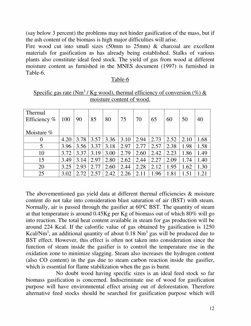
Table-6
Specific gas rate (Nm3 / Kg wood), thermal efficiency of conversion (%) &
moisture content of wood.
Thermal
Efficiency %
Moisture %
100
90
85
80
75
70
65
60
50
40
0 4.20 3.78 3.57 3.36 3.10 2.94 2.73 2.52 2.10 1.68
5 3.96 3.56 3.37 3.18 2.97 2.77 2.57 2.38 1.98 1.58
10 3.72 3.37 3.19 3.00 2.79 2.60 2.42 2.23 1.86 1.49
15 3.49 3.14 2.97 2.80 2.62 2.44 2.27 2.09 1.74 1.40
20 3.25 2.93 2.77 2.60 2.44 2.28 2.12 1.95 1.62 1.30
25 3.02 2.72 2.57 2.42 2.26 2.11 1.96 1.81 1.51 1.21
The abovementioned gas yield data at different thermal efficiencies & moisture
content do not take into consideration blast saturation of air (BST) with steam.
Normally, air is passed through the gasifier at 60oC BST. The quantity of steam
at that temperature is around 0.45Kg per Kg of biomass out of which 80% will go
into reaction. The total heat content available in steam for gas production will be
around 224 Kcal. If the calorific value of gas obtained by gasification is 1250
Kcal/Nm3, an additional quantity of about 0.18 Nm3 gas will be produced due to
BST effect. However, this effect is often not taken into consideration since the
function of steam inside the gasifier is to control the temperature rise in the
oxidation zone to minimize slagging. Steam also increases the hydrogen content
(also CO content) in the gas due to steam carbon reaction inside the gasifier,
which is essential for flame stabilization when the gas is burnt.
No doubt wood having specific sizes is an ideal feed stock so far
biomass gasification is concerned. Indiscriminate use of wood for gasification
purpose will have environmental effect arising out of deforestation. Therefore
alternative feed stocks should be searched for gasification purpose which will
13
have woody characteristics. The most accepted material in lieu of wood is rice
husk particularly in India. On an average yield of rice husk is 20% of the paddy
& considering the total output of paddy in India the availability of rice husk could
be abundant. Use of rice husk in gasifier has been well established.
Rice husk is a difficult material both for combustion & gasification
compared to other biomasses. It requires longer time to react due to its Silica-
Cellulose structure. This special feature coupled with the ideal size & texture had
generated somewhat low bulk density characteristics (BD is 125 to 150 Kg/m3).
Rice husk cannot be compacted easily for which in the gasifier the mass (rice
husk) provides space/ voidage for the air which is blown through the gasifier to
affect combustion/ gasification. However for efficient combustion special
attention is required towards intimate contact of husk with air & sufficient
reaction time. The chemical properties of rice husk are already given in Table-2.
Due to critical nature of rice husk & also higher reaction time for gasification, the
efficiency of the gasifier rarely exceeds 65%. The carbon lock in the cinder is as
high as 15-20%. Due to higher ash content in the rice husk (ash-19-22%) any
negligence in operation may create high temperature in the reaction zone & also
fusion of the ash to hinder flow of the material inside. The quality of gas will also
become poor. The performance of the gasifier may also be erratic. The reverse
effect may also be seen i.e. lowering of temperature in the reaction zones arising
out of malfunctioning of the gasifier. All these are indicated by the colour &
nature of the ash discharged. The yield of gas using rice husk in the gasifier has
been found to be 1.65 to 1.85 Nm3 /Kg rice husk. A yield of 1.70Nm3/Kg to
1.75Nm3/Kg rice husk (at 15% moisture) may be accepted as standard data. The
ash of rice husk contains 89-90% silica having ash fusion point above 1300oC.
Apparently ash from rice husk seems to be an attractive material for recovering
silica out of it. However for this purpose the ash requires to be completely made
free from the contamination of un-reacted rice husk. Besides this different
opinions exist about the usage of the ash of the rice husk as the source of silica
because of the heating effects inside the gasifier during gasification reaction. The
silica in ash is mostly in finely divided amorphous condition but effect of high
temperature in the oxidation zone of the gasifier tends to make it crystalline &
some part of the ash also combines with carbon with the formation of inert black
ash. This type of ash has been stated to be even worse than river sand.
REACTION FUNDAMENTALS OF PRODUCER GAS GENERATION:
The energy required for gasification is derieved from within the system in the
oxidation zone where air generates the required heat during combustion reaction
to initiate all the other reactions in different imaginary zones which could be
overlapping with one another. It is quite important to maintain these zones in
their appropriate status to obtain a gas of required quantity & quality in a

14
consistent manner. The air which is pushed through the gasifier should match the
actual requirement which is in the order of 1.6 to 1.8Kg/Kg of biomass. If the air
is in excess of the need, the reaction zones will not only be disturbed but un-
reacted air will come out with the gas with all its adverse consequences. The
different stages involved in gasification are as follows:
Oxidation:
C+O2 = Co2 + Heat (+393 MJ/k mol)
Hydrogen available in the fuel reacts with oxygen in the air-
H2 +1/2. O2 = H2O + Heat (+242 MJ/k mol)
Temperature of the bed 1000-1200oC
Reduction:
Temperature condition 550-800oC
Boudouard Reaction:
CO2 + C = 2CO – Heat (-164.9MJ/k mol)
Water gas reaction:
C+H2O = CO+H2 – Heat (-122.6MJ/k mol)
The reduction reactions are all endothermic bringing down the temperature in
that zone to around 600-700oC.
Water shift reaction:
CO + H2O = CO2 +H2 + Heat (+42MJ/k mol)
Methane reaction:
C+2H2= CH4 + Heat (+75MJ/k mol)
In the case of biomass gasification the methane reaction is very nominal. The
appearance of methane in the gas is primarily due to distillation of the biomass by
the carrier gas evolved during oxidation & reduction reactions.
Pyrolysis/ Distillation of Biomass:
The gas leaving the oxidation reduction zone at a temperature of about 550-
700oC passes through the dry biomass distilling it into three products namely bio-
char, tar & watery substance called Pyrolignious liquid & gases containing
Carbon dioxide, Carbon monoxide, Hydrogen, methane, little quantity of oxygen,
Nitrogen etc. In this zone the temperature is reduced to about 300 to 350oC.
Drying of Biomass:
The mixture of hot gases at 300- 350oC then passes through the biomass as
charged from the top. As the gas passes through the wet mass, moisture is driven
15
out along with all other volatile products in the oxidation, reduction & distillation
zones. The gas comes out of the generator at about 80-200oC in the case of
updraft gasifier & 400-500oC in the case of downdraft gasifier. The temperature
of the exit gas also depends on the moisture content of the gas, type of biomass &
the design of the gasifires. In the case of wood, temperature of the gas coming
out may touch 250oC.
The temperature conditions as given above are rather approximate. The concept
of different zones is also imaginary for conceiving the chemistry of gasification
reactions. Nobody knows what is actually going inside the gasifier.
TYPES OF GASIFIERS:
Generally, gasifiers are of four types.
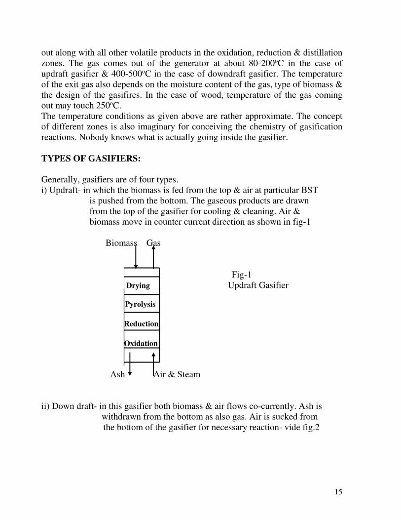
i) Updraft- in which the biomass is fed from the top & air at particular BST
is pushed from the bottom. The gaseous products are drawn
from the top of the gasifier for cooling & cleaning. Air &
biomass move in counter current direction as shown in fig-1
Biomass Gas
Fig-1
Drying Updraft Gasifier
Pyrolysis
Reduction
Oxidation
Ash Air & Steam
ii) Down draft- in this gasifier both biomass & air flows co-currently. Ash is
withdrawn from the bottom as also gas. Air is sucked from
the bottom of the gasifier for necessary reaction- vide fig.2

16
Biomass Air
Drying
Pyrolysis Fig. - 2
Downdraft Gasifier Oxidation
Reduction
Ash Gas
ii) Cross draft- in this gasifier the biomass is fed from the top, air is pushed
to the biomass obliquely from the side of the gasifier which
is about 2/3rd downward from the top & gas is taken out
from the other side of the gasifier which is almost at the
bottom end. The arrangement is shown in fig.3.
Biomass Fig-3
Cross draft Gasifier
Drying
Pyrolysis
Gas
Oxidation
Air Reduction
Ash

17
iv) Fluid Bed- such gasifiers with circulating system using air as fluidization
as well as reaction media with biomass operate as in any
fluid bed system. Particles entrained in the gas coming out
of the gasifier are entrapped in a cyclone & re-circulated.
Reaction takes place at a temperature of 1000-1100oC.
Specific gas production is around 2.4 Nm3/Kg of dry biomass
with cold gas efficiency of about 80%. Tar in gas is low.
The arrangement is shown in figure-4.
Systems had also existed to convert biomass/municipal waste
into gas in two stages. In the first stage the volatile products
containing major quantity of carbon are driven out leaving
behind the fixed carbon (overall 18 to 19% carbon) for
gasification in fluid bed using steam. Carbon efficiency of
such system is obviously very low due to loss of carbon at
the initial stage of devolatilasation.
Fig-4
Fluid Bed Gasification
Gas & solid particles
Cyclone dust free gas for
purification
Biomass in Drying Pyrolysis
Oxidation
Reduction
(Fluid bed solid particles
Gasification) recycled
Ash out
Air in

18
SHORT EVALUATION OF GASIFICATION PROCESSES:
The type of gasifier to be adopted mostly depends on the choice & need of the
entrepreneur, availability of the biomass at an acceptable price, cost of the units,
flexibility of operation & magnitude of gas generation.
The updraft gasifiers have a primitive history which had followed the pattern of
gasification in coal/coke gasifiers & as such their developments using biomass
had the advantage to copy the established techniques. Therefore, the updraft
gasifiers could be built in large sizes in single unit. In updraft gasifiers biomass
with somewhat higher moisture content can be used. Reactions inside the
gasifiers are more or less uniformly distributed & the gas produced has low
oxygen content (less than 2%). It is true that the tar content in the crude gas is
high (4gms to 7gms/Nm3) as all the tar from the distillation zone come out with
the gas. The liquor produced is of pyrolignous type containing aldehydes,
ketones, acetic acid etc. This liquor is highly corrosive (Ph 3 to 5) & requires to
be neutralized by alkali. The BOD & COD values are also high (16,000 to
20,000). Therefore the excess liquor before discharge requires elaborate
treatment. Tar produced is somewhat unrecoverable since it comes out as sludge
mixed with solid materials. Entrepreneurs who need more gas (say more than
1000Nm3/hr) might prefer to have large units which the updraft type can provide.
Tar from the gas can also be removed to any desired level using appropriate gas
cleaning system. There could be no hindrance in adopting updraft technology
from a capacity level of 20KW to 600KW in single units. For larger plants
multiple units may be installed. The plant with all its units is sturdy in
construction, can run continuously for years together with appropriate operation
& maintenance. The gas produced from updraft gasifiers have been successfully
used for various thermal applications & also for power generation in dual fuel
engines where 65-70% diesel oil could be replaced in several plants for years
together. Application of this gas in 100% gas engines is also under trial. Gas
produced from updraft gasifiers using rice husk has a characteristic smell which
is highly repellant. As such it is advisable not to install such plants in populated
areas. The calorific value of the clean gas is 1200-1350 kcal/Nm3. the yield of gas
is 1.65 to 1.85Nm3/Kg (average 1.75).
The downdraft gasifiers are relatively of smaller sizes & for large quantity of gas
more number of units of small sizes are to be installed. Downdraft gasifiers have
well been standardized from 100kw to 350kw. Some larger sized units have also
been set up but do not seem to be so well established as in the case of updraft

19
types. Downdraft gasifiers use mostly wood. The number of downdraft gasifiers
is much more than that of updraft type because of low cost & smaller sizes which
are preferred by the small industries. The tar content in crude gas is low (2 to
3gms/Nm3) compared to that in updraft gasifiers. The liquor produced has also
less oxygenated organic compounds because both tar & liquor pass through the
oxidation zone while coming out from the bottom. This type of flow of gas
through the hot zone destroys the repelling constituents in the gas. Tar also gets
somewhat cracked in the hot zone during its passage downwards. This creates
problem in the gas off take pipe connecting the wet scrubber as pitchy materials
gets deposited in this pipe which has to be cleaned too often. The outlet gas
temperature from the gasifier to the wet scrubber is very high (450 to 550oC)
which means the cold gas efficiency is low. The calorific value of the gas is 1050
to 1100 kcal/Nm3 as against 1250 to 1350oC in updraft gasifier. The gas cleaning
& purification section consists of a series of gas filtration units (filtration media,
rice husk or saw dust) which have to be cleaned/replaced quite frequently. The
gas contains as in the case of updraft system 35-38% CO plus H2 but oxygen
content in gas is high. Liquor before discharge requires also to be treated. Even
then the popularity of downdraft system has prevailed not only in India but also
other parts of the world, perhaps due to patronization from various institutions &
also the simplicity of construction & low cost. Purified gas from downdraft
system has also been used (besides thermal application) for power generation in
dual fuel system.
The cross draft gasifiers are also quite simple in construction. These gasifiers use
wood for gasification. In many places the gas is not cleaned & the raw gas is
directly used in thermal application. Everyday the gas pipelines are cleaned.
The fluid bed system though not widely used in gasifying biomass in large
scale has the inbuilt advantage of having an excellent uniformity in temperature
distribution within the mass, efficient contact between solid & gaseous phase &
high volumetric capacity of the equipment associated with rigid temperature
control in the gasifier. Fuels which have high ash content seem to be more
suitable in the fluid bed system. However, these advantages are offset by the
complexity of the system & production of more dust & considerable quantity of
tar in the gas.
COOLING & CLEANING OF GAS:
The temperature of the gas coming out of the generator is normally 350 to 550oC
for downdraft & for fluid bed gasifiers it is much higher (800 to 900oC). In the
case of updraft system with appropriate operation it is in the range of 80oC to
150oC when using rice husk. While gasifying wood it may go up to 250oC. In
most of the systems the crude gas coming out of the gasifiers are scrubbed with
20
liquor/water to bring down the temperature to about 45-50oC & also remove dust
& tar to the maximum possible extent. Thereafter various types of cooling &
cleaning appliances are used to reduce the tar content in the gas step by step
details of which are beyond the scope of this paper. The cleaning appliances are
determined by the extent of reduction of tar & solid particulate matter in the gas
as may be required in different usages.
EFFLUENT TREATMENT:
The source of the liquid effluent is the moisture content in the biomass & its
distillation products generating additional liquor & also tar. If the moisture
content in biomass is 15%, the liquor generated due to hydrogen & oxygen
reaction within the biomass is another 6% & the total quantity of liquor produced
in the system will be 21%. To this another 2% may be added for undecomposed
steam. For all practical purpose the total liquor yield may be taken as 25% or so.
The liquor is usually mixed with tar which has low temperature characteristics.
This liquor has to be analyzed for its characteristics & accordingly the treatment
facilities are to be provided. In a nutshell the facilities may include primary
filtration/decantation for separation of tar & other solids, aero-flotation of tar by
using air (AFT), chemical dosing, sludge separation, separation of the clean
liquor, aeration of the clean liquor for reduction of BOD & COD to the desired
level. Before discharging the treated effluent it is customary to dilute it with fresh
water. A part of this treated effluent water is re-circulated in the gasification
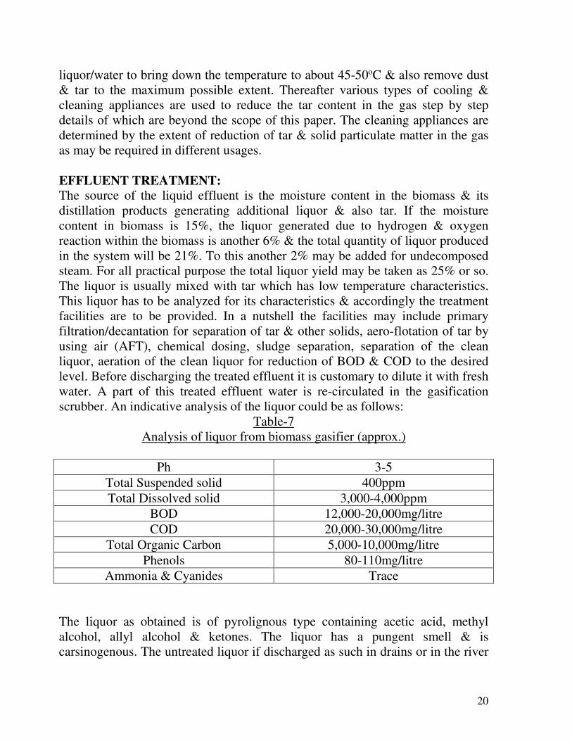
scrubber. An indicative analysis of the liquor could be as follows:
Table-7
Analysis of liquor from biomass gasifier (approx.)
Ph 3-5
Total Suspended solid 400ppm
Total Dissolved solid 3,000-4,000ppm
BOD 12,000-20,000mg/litre
COD 20,000-30,000mg/litre
Total Organic Carbon 5,000-10,000mg/litre
Phenols 80-110mg/litre
Ammonia & Cyanides Trace
The liquor as obtained is of pyrolignous type containing acetic acid, methyl
alcohol, allyl alcohol & ketones. The liquor has a pungent smell & is
carsinogenous. The untreated liquor if discharged as such in drains or in the river

21
will kill all flora & funa & also fish. When the liquor is produced in small
quantity from small gasifiers treatment of this small quantity liquor may not be
necessary. It may be filtered through the ash produced from rice husk.
CHARACTERISTICS OF PRODUCER GAS:
Table 8 gives the characteristics of producer gas obtained from biomass. For the
sake of comparison composition of some other industrial gases are also given.
Table-8
Characteristics of producer, coke oven & natural gas.
Gases Biomass
Updraft
Biomass
Downdraft
Coal
Based
producer
Coke oven
gas
Natural
Gas
Composition
(% V/V):
CO2 8-10 12-13 5-6 4 2-7
CnHm 0.2 - 0.4 - 0.4 2.5 -
O2 0.6 - 1.5 Not
specified
0.6 0.5 -
CO 23-26 17-20 26 8 -
CH4 1.5-2.0 1.5-2.0 4.0 26 91-93
H2 10-12 17-19 12 51.0 -
N2 52-54 Not
Specified
49-50 8 -
C.V.(gross)Kcal/Nm3 1200-1350 1050-1100 1450-1550 4200-4700 8650-
8850
Spgr. (Air=1) 0.9 0.91 0.90 0.45 0.6
Viscosity(centipoises) 0.0195-
0.0198
0.0195-
0.0198
0.0195-
0.0198
0.0137 0.0125
Sp.Heat 0.32 0.32 0.32 0.33 0.34
Air reqd. for
combustion with no
excess air(V/V)
1.0-1.2 0.9-1.0 1.4-1.5 4.5-4.6 9.0
Waste Gas vol. with
no excess air(V/V)
1.8 1.8 2.3 5.5 11
CO2 content in waste
gas (%)
19-20 18-19 18-19 9-10 8.5-9.5
NB: i) For combustion of gases about 20-30% excess air is used which increases the waste
gas volume & decreases the carbon dioxide content.
ii) BTU/Scuft39.55= Kcal/Nm3. iii) Viscosity data may vary by 5% to 10%.

22
The working data available on fluid bed gasifiers are as follows:
a) Specific gas production-2.2 to 2.4 Nm3/Kg of dry biomass.
b) Gasification temperature-1100-1200oC
c) Gas composition- CO2 10%, CnHm 1%, O2 less than 1%, H2 21%, CO
22%, CH4 2%, N2 43%
d) Gross calorific value- Kcal/Nm3= 1380.
In Table 8 the characteristics of producer gas & other industrial gases like
coke oven gas & natural gas have been given. For the sake of comparison the
salient technical data on LPG are given below:
LPG is a mixture of 40% propane & 60% butane in admixture with very
small quantity of ethane. Though LPG is a gas, it is compressed in cylinders at
about 90lb/inch2 by which it is converted into liquid in the cylinder.
a) Its calorific value is 11,840 to 11,900 (gross) & 10,920 (net) in terms of
Kcal/Kg. Volumetrically the calorific value (gross) is 28,460 & 26,260
(net) Kcal/Nm3.
b) Specific gravity in vapor form is 1.80 (air = 1).
c) Bulk density is 2.33Kg/Nm3.
d) Volume of gas 0.45 to 0.48 Nm3/Kg LPG.
e) In liquid form if density is 0.55 Kg/litre.
f) Air required for combustion is 29Nm3/Nm3 LPG (11- 12Nm3/Kg).
g) Carbon dioxide content in flue gas (without excess air) 14-15%.
h) Flue gas volume 30-32Nm3/Nm3 LPG.
i) Ignition point oC 410-580.
j) Limits of inflammability lower 1.8 upper 9.5 in %.
k) Ethyl Mercaptan is added as an odorant to detect LPG leakage.
GASIFIER FUNCTIONAL GNOSTICS & ARITHMETICS:
Certain fundamental data are necessary to evaluate the performance of
gasifiers which are indicated below:
1. Acceptance of the raw materials used in a particular type gasifier, its shape,
bulk density, proximate analysis, ash fusion point etc details of which have
been dealt in earlier paragraphs (vide Table 2-5 as well).
2. Evaluation of gas output takes into consideration the heat input in the
gasifier i.e. calorific value of the biomass plus the heat input by steam,
gasification efficiency & the calorific value of the biomass gas as could be
expected. Generally while using wood for gasification, the efficiency is taken
at 75% & using rice husk it could be 65%. Moisture content in biomass may
be taken as 15%.
23
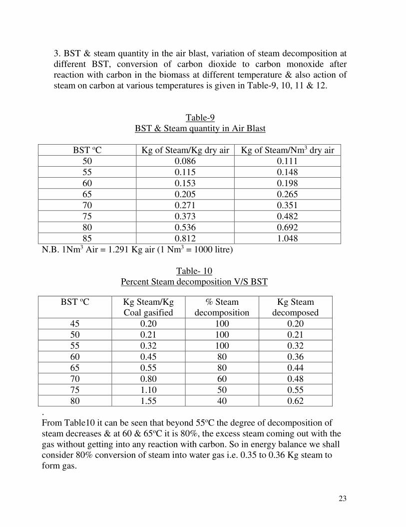
3. BST & steam quantity in the air blast, variation of steam decomposition at
different BST, conversion of carbon dioxide to carbon monoxide after
reaction with carbon in the biomass at different temperature & also action of
steam on carbon at various temperatures is given in Table-9, 10, 11 & 12.
Table-9
BST & Steam quantity in Air Blast
BST oC Kg of Steam/Kg dry air Kg of Steam/Nm3 dry air
50 0.086 0.111
55 0.115 0.148
60 0.153 0.198
65 0.205 0.265
70 0.271 0.351
75 0.373 0.482
80 0.536 0.692
85 0.812 1.048
N.B. 1Nm3 Air = 1.291 Kg air (1 Nm3 = 1000 litre)
Table- 10
Percent Steam decomposition V/S BST
BST oC Kg Steam/Kg
Coal gasified
% Steam
decomposition
Kg Steam
decomposed
45 0.20 100 0.20
50 0.21 100 0.21
55 0.32 100 0.32
60 0.45 80 0.36
65 0.55 80 0.44
70 0.80 60 0.48
75 1.10 50 0.55
80 1.55 40 0.62
.
From Table10 it can be seen that beyond 55oC the degree of decomposition of
steam decreases & at 60 & 65oC it is 80%, the excess steam coming out with the
gas without getting into any reaction with carbon. So in energy balance we shall
consider 80% conversion of steam into water gas i.e. 0.35 to 0.36 Kg steam to
form gas.
24
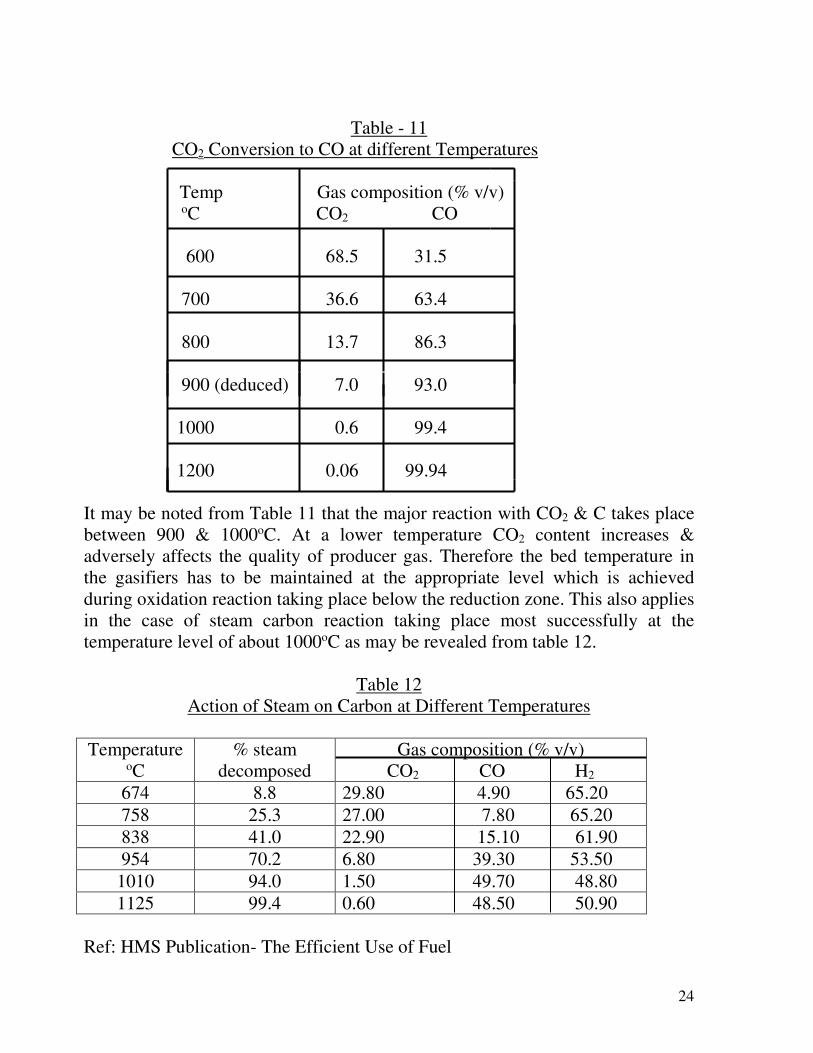
Table - 11
CO2 Conversion to CO at different Temperatures
Temp Gas composition (% v/v)
oC CO2 CO
600 68.5 31.5
700 36.6 63.4
800 13.7 86.3
900 (deduced) 7.0 93.0
1000 0.6 99.4
1200 0.06 99.94
It may be noted from Table 11 that the major reaction with CO2 & C takes place
between 900 & 1000oC. At a lower temperature CO2 content increases &
adversely affects the quality of producer gas. Therefore the bed temperature in
the gasifiers has to be maintained at the appropriate level which is achieved
during oxidation reaction taking place below the reduction zone. This also applies
in the case of steam carbon reaction taking place most successfully at the
temperature level of about 1000oC as may be revealed from table 12.
Table 12
Action of Steam on Carbon at Different Temperatures
Temperature oC
% steam
decomposed
Gas composition (% v/v)
CO2 CO H2
674 8.8 29.80 4.90 65.20
758 25.3 27.00 7.80 65.20
838 41.0 22.90 15.10 61.90
954 70.2 6.80 39.30 53.50
1010 94.0 1.50 49.70 48.80
1125 99.4 0.60 48.50 50.90
Ref: HMS Publication- The Efficient Use of Fuel

25
The composition of gasification gas will depend on temperature condition in the
gasifier, extent of carbon dioxide & carbon reaction, gas produced by steam
carbon reaction & finally the composition of the distillation gas evolved from the
top of the reduction zone. All the gaseous constituents evolved along with tar &
water vapor arising out of different pyrolysis reactions within the biomass come
out of the reactor as producer gas. The tar, condensed water vapor (called liquor)
& other impurities are removed from the gas to tune the gas at the desired purity.
Normally for thermal application tar content in gas may be kept at 50mg/Nm3 &
for power generation in dual fuel engine & 100% gas engine below 10mg/Nm3
details of which will further be discussed in the utilization chapter.
Characteristics of biomass based producer gas are given in Table 8 in the
preceding chapter.
4. MASS & ENERGY BALANCE
Table 13
Basis of Calculation
Particulars Wood Rice Husk
Biomass 1Kg at 2% ash & 15%
moisture
1Kg at 20% ash & 15%
moisture
Calorific Value 3700 Kcal/Kg 2900 Kcal/Kg
Gas Output 2.3 Nm3/Kg at
1250Kcal/Nm3
1.75 Nm3Kg at
1250Kcal/Nm3
Tar 0.03Kg/Kg 0.015Kg/Kg
Liquor 0.22Kg/Kg 0.21Kg/Kg
In addition to the above there are some other inputs like steam & air. The
quantity of steam at 60oC BST will be 0.45Kg/Kg biomass which will go as input
to the producer plant. The entire quantity will not go into reaction & only 80% of
it i.e. 0.36Kg/Kg of biomass will react with carbon in the biomass. The quantity
of air required for gasification will be 1.78Kg/Kg of wood & 1.61Kg/Kg of rice
husk. All such figures have been taken from working data which also vary. This
happened because of the complexity of the reactions taking place within the
gasifier using different types of biomass. Minor variations will not affect the
ultimate results of calculations.

26
A. MASS BALANCE WOOD RICE HUSK
i) Inputs Wood 1.00Kg Rice Husk 1.00Kg
Steam 0.45Kg Steam 0.45Kg
Air 1.78Kg Air 1.61Kg
Total Inputs 3.23Kg 3.06Kg
ii) Outputs Gas 2.50Kg (2.3Nm3) Gas 1.902Kg (1.75Nm3)
Ash 0.025Kg (dry) Ash 0.250Kg (dry)
Tar 0.030Kg Tar 0.0150Kg
Liquor 0.220Kg Liquor 0.21Kg
Total Outputs 2.775Kg 2.377Kg
Product Efficiency % 85.90 77.70
(Input/Output)
Efficiency of Gas 77.40 62.20
Production %
The material balance does not have much significance. The significant item is the
efficiency of gas production.
B. ENERGY EFFICIENCY (in totality)
SL.
NO
Particulars Wood (1Kg) Rice Husk (1Kg)
1. Heat Input (Kcal/Kg) 3700 2900
Heat in Steam (Kcal) at 60oC
for 0.45Kg steam
279 279
Total Heat Input 3979 3179
2. Heat from Product (Kcal/Kg)
Gas 2875 2188
Tar 276 138
Total Heat Output 3151 2326
3. Energy Efficiency %
Heat output!heat input
79.20
73.20

27
C. COLD GAS EFFICIENCY
WOOD RICE HUSK
ηc %
2.331250
▬▬▬▬3100 ═ 72.30%
3979
1.7531250
3100 ═ 68.80%
3179
D. HOT GAS EFFICIENCY
WOOD RICE HUSK
ηh %
(2.333331250)+2.333330.323333(150-35)
3979
═ 74.4%
(1.7531250) + 1.7530.32(150-35)
3179
═ 70.80%
In the above calculations specific heat of gas has been taken at 0.32, base gas
temperature at 35oC, gas temperature outlet gasifier at 150oC & calorific value of
gas at 1250 (gross) Kcal/Nm3.
The above calculations are only indicative & not absolute.
APPLICATION OF PRODUCER GAS FROM BIOMASS
1. Thermal
Application of producer gas for thermal use is vast. Producer gas obtained
by gasifying coal has higher calorific value (1450-1550Kcal/Nm3) & higher
flame temperature (1800oC) compared to those of gas obtained by gasifying
biomass. The flame temperature of biomass gas is between 1550 & 1600oC & the
average calorific value of gas is 1200Kcal/Nm3. Using producer gas from
biomass, temperature in a well designed furnace can be attained up to 900oC
without preheating of air/ gas. If a furnace is operated continuously one can
expect furnace temperature up to 1000oC or near about. However, if the furnace

28
temperature drops due to introduction of a material inside or due to any other
reason, time required to attain the desired temperature(i.e. pick up time) will be
quite long compared to that of fuel oil or any other fuel having higher calorific
value than biomass based producer gas. The general usage pattern of biomass
based producer gas are-
a) Heating furnaces to replace fuel oil.
b) Replacement of fuel oil in boilers of smaller capacities.
c) Melting furnaces like aluminum melting (m.p. 660oC), zinc (m.p. 419oC),
lead (m.p. 327oC) etc. Though the temperature of the metal might be low,
the furnace temperature has to have in the region of 800 to 850oC for quick
temperature pick up and safe ignition of gas.
d) For hot air generation in various industries.
e) Bakery, biscuit & other food product units. Producer gas used should be
cleaned & thoroughly purified for this purpose.
f) The possibility of use of biomass based producer gas to dry of tea leaves
has been under consideration for sometimes. For this purpose the
temperature of the waste gas after burning producer gas has to be
maintained at about 120oC & the gas must be completely free from tar &
other impurities to ensure that the flavor of the tea does not get disturbed.
Some key fundamentals for replacement of fuel oil by biomass based producer
gas are produced below:
One liter F.O. of specific gravity 1.0 (approx) will have heat value
10170Kcal/Kg. heating value of producer gas 1250Kcal/Nm3.
Equivalent gas = 10170/1250 = 8.14Nm3/Kg fuel oil.
In replacing fuel oil by producer gas, due to higher stack loss arising out of
higher quantity of waste gas volume, about 25% excess gas will have to be
used in the furnace.
Amount of gas to be used = 8.1431.25 = 10.20Nm3 gas to replace 1Kg fuel
oil. Air required for the same will be 12Nm3 with 20% excess air. So total
waste gas generated by burning producer gas will be 22Nm3.
Air requirement (theoretical) to burn 1Kg fuel oil = 10Nm3.
Excess air used for combustion will be 20%. So total air requirement for
burning fuel oil will be 12Nm3 (1031.2). Waste gas volume will be only
12Nm3. This means an increase in about 10Nm3 waste gas (22-12Nm3) i.e.
83.30% in an effort to replace fuel oil by producer gas having low calorific

29
value. This excess volume of waste gas has to be evacuated from the furnace
without any design modification of the system meant to be operated using oil.
The result will culminate in generation of higher stack temperature compared
to that while using oil. If the system is meant to replace fuel oil in a boiler,
one cannot expect the same output of steam from the boiler by using producer
gas. There will be 25-30% derating of the boiler output. One might try to
compensate this by using a dual fuel burner through which along with gas
some oil could be fired. This effort unfortunately may be unacceptable by the
system & temperature of the flue gas will start rising instead of improving the
boiler output. This type of irregularity could perhaps be resolved by changing
the furnace combustion volume & also the design of the boiler. Otherwise one
has to be satisfied with a derated system. Mere pushing more gas in an
existing system cannot solve the problem as the furnace will not accept those
manipulations. It might so happen that the excess gas could be seen burning at
the top of the chimney. Therefore before replacing oil or LPG or any fuel
having substantially higher calorific value compared to that of producer gas,
the furnace design & other aspects will have to be thoroughly checked. Any
arrangement involving handling of gas should take care of the safety aspects
both for the man & machinery. If the furnace is red hot the chances of
explosion is less but there could be serious back pressure to cause heavy
damage. In case the furnace is not red hot & the flame gets extinguished,
before relighting the gas the furnace should be purged with air & then
relighted. It is advisable to maintain a pilot flame in front of the firing zone to
minimize sudden explosion.
The other aspect is the length of the flame of the gas. In case the furnace is
very lengthy there could be problems in the attainment of the required
temperature throughout the entire length & breadth of the furnace unless
provisions are made to install gas burners at the dead zones.
Last but not the least the chance of a gas flame from a burner traveling
backwards has to be carefully guarded by installing flame arresters in the gas
pipeline leading to the burner. Alternately the gas may be passed through a
water seal followed by an anti pulsation tank. The backward travel of the
flame is a disturbing feature which has created lots of problems in plants
causing explosion & back fire.
Use of producer gas in the tea industry for drying tea leaves may be ventured.
In such case the gas obtained from the gasifier has to be thoroughly cleaned
from tar & other impurities and then burned & mixed with sufficient excess
air in order to achieve the desired waste gas temperature of about 120oC. The
30
mixture of waste gas at that temperature can be directly passed through the tea
dryer (as is normally practiced) while using natural gas or oil. The following
calculations will give an idea of specific fuel consumption values (ref: Palit D,
Research Associate, The Energy & Research Institute, TERI dated 8th May,
2006).
Dryer capacity 300 Kg made tea/hour.
Hot air flow 11,400 Kg/hour.
It is required to calculate the quantity of wood for gasification purpose.
Calculations:
Total heat in hot air = 1140030.243(120-20) = 273600Kcal where 0.24 is the
specific heat of air on mass basis. If the calorific value of the gas obtained by
gasification of wood is 1250Kcal/Nm3 total requirement of producer gas would
be = 273600/1250 = 220Nm3/hr. But we have to use about 25% more gas to
compensate the high stack loss. Therefore requirement of gas will be in the order
of 275Nm3/hr. If the yield of gas from the gasification unit is 2.3Nm3/Kg wood,
requirement of wood would be 275/2.3 =120Kg wood/hr which means
requirement of wood for gasification purpose would be (1204300) Kg = 0.40Kg.
In other words 0.40Kg wood would be required for 1Kg made tea. One must be
very careful to ensure that neither the quality of tea nor its flavor is degraded.
2. Electrical.
Power generation may be through dual fuel engine or 100% gas
engine. For this purpose the gas has to be very clean, the particulate matter &
tar content should be less than 5ppm (though some say below 10ppm.) The
quality & quantity of gas for the purpose should have consistency. The
pressure supplied to the engine should be at a specific level without variation.
In the case of gas engine these stipulations are very rigid for smooth running
of the engine. In the dual fuel engine the variations are taken care of through
supply of diesel inside the engine. Success of producer gas based gas engines
meets diversified opinions regarding their long term use. However dual fuel
engines have crossed most of the hurdles in this respect & 60-70% diesel
replacement is quite common. It is true that the life span of the engines get
reduced by 30-35%. Attempt to increase diesel replacement by producer gas
more than 65% should be restricted since in an effort to save oil the engine
may get damaged. Moreover use of high gas rate makes the engine very hot.
Some basic calculations in respect of application of producer gas in engine are
furnished below:

31
We know 860Kcal = 1Kw.
C.V. of diesel oil = 11,700Kcal/Kg or 9832Kcal/liter (sp.gr of diesel 0.84)
Therefore theoretical power generation = 11700/860 = 13.6Kw.
Efficiency of power generation = 25%.
Therefore 1Kg of diesel (1.19 liter) will generate 13.630.25 = 3.4Kw or 1 liter
of diesel will generate (3.4 41.19) = 2.90Kw power. In other words for 1Kw
power diesel consumption will be (142.9) = 0.345liters rounded to 0.35liter
equivalent to 0.3539832Kcal = 3441Kcal.
Producer gas consumption = 3441/1250 = 2.75Nm3 (C.V. of producer gas
being 1250Kcal/Nm3). If the producer gas yield per Kg of husk is 1.75Nm3,
then requirement of husk will be (2.7541.75) = 1.571Kg/Kw of power in
100% gas engine, where to produce 1Kw power about 0.35 liter diesel was
required. Since use of producer gas to replace oil enhances the stack loss in
terms of total heat one has to use (as mentioned before) about 25% more gas
i.e. 25% more husk which is gasified. Taking this aspect into consideration,
requirement of rice husk will be-
1.57131.25 = 1.96Kg. This consideration is very important in evaluating the
gasifier capacity as well as the economics of such proposal.
In the case of wood the gas production is 2.3Nm3/Kg wood. The calorific
value of the producer gas will remain the same as in the case of rice husk.
However the requirement of wood will be reduced as shown below:
Producer gas consumption = 3441/1250Nm3 = 2.75Nm3/Kw.
Wood requirement (2.7542.3) = 1.2Kg/Kw in place of 1.57 while using husk.
Adding 25% extra wood requirement would be = 1.2Kg31.25 = 1.5Kg/Kw
power.
MNES now (MNER) in their publication
BIOMASS THERMO-CHEMICAL CHARACRETISATION (2nd Edition)
has published interesting data in respect of diesel oil consumption vis a vis
producer gas requirement as replacement fuel against diesel oil. The author
has deduced the diesel oil replacement value at different levels of replacement
using producer gas generated from rice husk as well as wood. For the purpose
the author has taken little higher value of diesel oil (0.37 liter) to produce
1Kw power.

32
Table 14
Diesel oil replacement in engines by Producer gas (basis 1Kw)
Diesel
displacement
%
Diesel
displaced
liter
Kcal
Equivalent
producer
gas Nm3
Rice
Husk
Kg/Kw
Rice
Husk
(25%
extra)
Kg/Kw
Diesel
used
liter/hr
Kcal
used
100 0.37 3638 2.91 1.66
(1.26)
2.10
(1.58)
Nil Nil
90 0.33 3245 2.60 1.50
(1.14)
1.87
(1.43)
0.04 393
85 0.31 3048 2.44 1.40
(1.07)
1.76
(1.34)
0.06 590
80 0.30 2950 2.36 1.35
(1.03)
1.66
(1.26)
0.07 688
75 0.28 2753 2.20 1.26
(0.96)
1.56
(1.18)
0.09 885
70 0.26 2556 2.04 1.16
(0.89)
1.45
(1.08)
0.11 1082
65 0.24 2360 1.89 1.08
(0.82)
1.35
(1.02)
0.13 1278
60 0.22 2163 1.73 1.00
(0.76)
1.25
(0.95)
0.15 1474
NB: The figures in the bracket stand for usage of wood.
The above table (Table No. 14) is self explanatory by itself. It is obvious
that for generation of 1Kw power in gas engine, about 1.70 to 2.00Kg of rice
husk will be required. If wood is used the requirement of wood would range from
1.30 to 1.60Kg/Kw power. Use of 100% producer gas in gas engine is yet
debatable for sustainable operation.. It is stated that a gas engine which is being
operated by natural gas will be derated by 30-35% when natural gas is substituted
by low energy density producer gas.
Compression ignition or diesel engine cannot be operated on 100% gas
without injection of some amount of diesel. This is because the producer gas
cannot ignite by itself under the operation pressure. Therefore the compression
ignition engines have to be operated on dual fuel mode. It is difficult to convert

33
such engines into spark ignition engines. In this case as well, derating will be
there. As thumb rule the dual fuel engine producing 1Kw power will require 1 to
1.1Kg of wood consuming 0.07 to 0.08 liters of diesel. For all practical purpose
diesel displacement by producer gas should not be forced beyond 70%. It has also
to be mentioned that for such operation not all type of diesel engines are suitable.
Producer gas application both in gas engine & dual fuel engine involves many
complicated calculations which are beyond the scope of this paper. More over
diversified opinions are not uncommon.
SELECTION OF BIOMASS BASED PRODUCER PLANT:
Selection of a biomass based producer gas will depend on the following:
a) Provenness of the technologies in commercial operation. Mere success in
the pilot scale cannot be relied upon.
b) Sturdy construction of the plant & good engineering practice.
c) Well established gas cleaning & gas purification system to produce the
desired purity in gas.
d) Proper selection of engine after thorough check of its performance using
producer gas.
e) Guaranteed after sales service by the plant supplier.
f) A good plant will need good money, an aspect which is often ignored
by the purchaser for short term benefit.
g) Availability of biomass in quality & quantity in appropriate physical
texture.
h) Lastly the price of the biomass & the economic aspect.
RISK FACTORS IN BIOMASS GASIFICATION:
i) Any biomass intended to be used in a gasification plant to produce gas
should be carefully tested in respect of its constituents, ash characteristics like
ash fusion & other physical properties to ascertain its acceptance in the
gasification process. Rice husk, saw dust & wood of particular shapes have
been well established for gasification. Any new biomass should not be used in
100% since behavior of such materials for the purpose may be unknown. Such
new materials should be tried in admixture with a well established biomass in
different proportion till sustained operation for at least 72 hours is attained.
Such procedure will show to what extent the new material may be used. At
each stage, the operational behaviors should be carefully examined & the gas
quality ascertained. It is very dangerous to play with gas & gasification
aspects in view of the likely hazards of explosion & other abnormalities.

34
ii) Gas explosion hazards in the plant caused by back fires & other ignition
factors associated with the concentration of high oxygen content in gas as
denoted by the lower explosives & higher explosive characteristics of gas.
iii) Tar & waste water management. Tar & pyrolignous liquor are
carcinogenic.
iv) Solid disposal.
v) Emission behavior.
vi) Population factors adjacent to the plant & noise pollution.
vii) Effluent disposal.
viii) Non adherence to the prescribed safety norms in relation to plant &
equipment & all electricals in a gas plant.
ix) No single person should be posted in a gassy area either for operation or
maintenance.
x) No smoking, no alcoholism & no naked flame in the plant area.
xi) CO poising for which the toxic effects of CO are given below.
Toxic effects of CO (approx)
SL.
NO
%CO PPM EFFECT
1 0.003 30 No significant effect
2 0.02 200 Headache in 2 to 3hours.
3 0.04 400 Headache, nausia within one hour.
4 0.08 800 Headache, Nausia within one hour & after that
within 45mins unconscious & collapse.
5. 0.16 1600 Headache, nausia within 20min & then death.
within 2 hours.
6. 0.32 3200 Nausia dizziness within 5-10mins & death in
30minuts.
7. 0.64 6400 Immediate unconscious & death in 10 minutes.

35
8 1.28 12800 Immediate death.
xii) Neat & cleanliness of the plant.
PLANT ECONOMICS:
Plant economics will depend on size of the plant, cost of inputs like biomass, oil,
labor etc & maximum utilization factors. It has been observed that about 80% of
the production cost depends on the biomass. Details are beyond the scope of this
technological paper.
CONCLUSION:
i) Since biomass has the same constituent (CHON) as in the case of coal & is
the forefather of coal, a fossilized solid fuel of vegetative origin, its
behavior towards gas generation follows the principle of coal pyrolysis. On
dry mineral matter free basis carbon in biomass is about 50% in contrast to
coal which has carbon content from 75 to 90%. Similarly, the calorific
value of biomass is 4450 to 4460 Kcal/Kg & that of coal 7800 to
8780Kcal/Kg (all on dry mineral matter free basis) depending on the rank
of coal. The fixed carbon content in biomass on dry mineral matter free
basis is 19 to 21%. Therefore, these simple indications in the analytical
results would be helpful to identify a particular material as biomass or the
other way.
ii) The term biomass also refers to renewable organic matter produced by
plants through photosynthesis with the help of solar energy combining carbon
dioxide & moisture to form the carbohydrates. Biomass also refers to wood &
woody products, agricultural residue, dung, weeds etc.
iii) Biomass gasification is a technology regarded as fuel switching to convert
the solid fuel to a gaseous fuel for different uses. Gasification adds value to
low or negative value solid feed stocks by converting them to marketable
products. Though gasification of coal is well known & well established,
gasification of biomass faces some problems which are specific to the
characteristics of the biomass. Many designs of gasifiers have been developed
with lucrative claims & many have perished. Frankly speaking multiple
gasifiers are rarely found successful because of the very nature of the biomass
& also the criticality of process parameters which often lead to problems.
iv) The major problem is biomass gasification relates to the cleaning of the
gas to make the same free from tar & other impurities including particulate
matter. The efficiency of gas cleaning is one of the fundamentals to the

36
success of a plant as a whole. Nature & treatment of the liquid effluent also
pose some difficulty so far cost is concerned though the plant size might be
small.
v) There are no definite values standardized for impurities in gas. The
application of gas in different usages has generated some values which are as
follows:
a) For thermal application tar & particulate matter less than 50mg/Nm3. For
specific thermal uses like biscuit manufacture, drying of tree leaves, drying
of Titanium dioxide, drying of Alufluoride etc, tar & particulate matter
should be less than 25mg/Nm3 & in certain other cases particularly in the
food industries the impurities should be less than 10mg/Nm3.
b) For dual fuel engines & 100% gas engines the tar & particulate matters
should be still lower (less than 5mg/Nm3). Some engine manufacturers
prescribe 100% pure gas. The fact is that nobody is sure about the gas
standard & everybody wants to follow the safest route.
c) CO & Oxygen content in the exhaust in an engine application (ref: CO &
PAH emission from engines operating on producer gas, Jesper
Arendfeldt, Technical University of Denmark).
Biomass based:
CO- mg/Nm3 300-500
O2 % about 5 (11% exception)
Natural gas/Bio gas:
CO- mg/Nm3 600-1000
O2 % 5.00
vi) All biomass cannot be gasified in line with the normal procedure
applicable for coal though the reaction chemistry in both the cases is the same.
To gasify a biomass it should have certain specialized characteristics which
will be acceptable in the gasification system.
vii) A diesel engine cannot run completely on producer gas. A dual fuel
system using producer gas & diesel oil has to be adopted. Normally 60-70%
diesel replacement by producer gas is advisable though higher displacement
up to 75% is achievable at the expense of the life of the engine.

37
viii) To produce 1Kw power in gas engine about 1.70 to 2.00Kg husk will be
required. If wood is used about 1.30 to 1.50Kg will be required.
ix) To produce 1Kw power diesel oil requirement will be 0.37 to 0.375liter.
x) Calorific value of biomass based producer gas is 1150 to 1300Kcal/Nm3 as
against 1450 to 1550Kcal/Nm3 using coal.
xi) Production of gas from 1Kg rice husk (15% moisture) is 1.65 to1.80Nm3,
from 1Kg wood (15% moisture) it is 2.30Nm3 for coal 2.50 to 2.70Nm3 based
on ash & moisture of coal. Yield of gas from high ash coal (above 35%) will
be less than 2.20Nm3/Kg. All these are dependent on the heating values of
coal or biomass.
xii) Biomass based gasification system does not offer wide applicability due to
technological limitations coupled with insufficient availability of the biomass.
For large scale thermal application like production of steam & power one would
like to burn biomass directly & adopt the turbine route.
xiii) The environmental benefits as claimed are too optimistic to be compared
with the wide CO2 emission in the various industries since burning producer
gas also gives rise to enough CO2 production.
xiv) One advantage worth consideration for adoption of biomass system
could relate to combined benefits of renewability & decentralized application
in relatively smaller scale.
ACKNOWLEDGEMENT:
The author thankfully acknowledges the active support of the CMPDIL in
the publication not only of this paper but also a series of paper in the
Minetech. The encouragement rendered by the CMPDIL has given enough
impetuous to the author to fulfill his mission.
BIBLIOGRAPHY:
i) Biomass based decentralized power generation & biomass management for
energy purposes by B.S. Pathak & N.S.L. Srivastava SPRERI Publication No.
2005/2 & 2005/3.
ii) Two days Regional Biomass Meet, the 8th May, 2006 Dibrugarh, Assam.

38
iii) Efficient use of fuel HMS Publication.
iv) Chakrabarti H.C. Biometry of Fuel, Integration of Properties & Heat
Utilization, Minetech, Vol. 15 No.-4 July-August 1997.
v) Anil K. Rajbanshi, Director, Nimbkar Agricultural Research Institute, Phaltan-
415523, Maharashtra, India- BIOMASS GASIFICATION.
vi) Chakrabarti H.C. Technological Aspects of Producer Gas Generation & its
Usage Philosophy, Minetech Vol. 18, No-5 & 6 September-December-1997.
vii) MNES Publication 1997- Biomass Thermo-Chemical Characterization.
viii) Hand Book- Biomass Gasification, editor Harry Knoes.
ix) 25 years of Renewable Energy in India, MNRE.
x) Towards Modernized Bio Energy, School of Energy Studies, Jadavpur
University, Kolkata.
xi) Chemical Engineers’ Hand Book, Perry 3rd Edition
xii) Chakrabarti H.C.- Air Blown Producer Gas from Coal: The New Generation
Energy Substitute, Minetech Vol. 32 April2June 2011.
xiii) Authors innumerable collections from different sources & his long practical
experience in the biomass arena including assessment & usage.
xiv) Authors expertise in coal quality assessment, coal technology, coal usage,
coke making, coal gasification & gas purification including analytical aspects.
HIRENDRA CHANDRA CHAKRABARTI
19-03-2012

39
NB This lead article was published in an international magazine “Minetech” Vol.
34 No. 3 September, 2013.