biomass gasification in entrained-flow systems · biomass gasification in entrained-flow systems...
TRANSCRIPT

Biomass Gasification in Entrained-Flow
Systems
Renewable Energy Council Meeting
Bismarck, North Dakota
March 24, 2011
Jason Laumb
Senior Research Manager
© 2011 University of North Dakota Energy & Environmental Research Center.

EERC . . . The International Center for Applied Energy Technology
Background
As the U.S. power industry prepares to comply with pending regulations
for greenhouse gas emissions, many are considering biomass fuels as
an option to reduce CO2 or to meet renewable fuel mandates.
Entrained-flow gasification offers certain benefits:
– Reduced hazardous air pollutant (HAP) emissions
– Higher carbon conversion
– Lower tar production
Challenges/Opportunities
– Limited data on entrained-flow gasification of biomass
– Feeding challenge
– Carbon kinetics
– Residence time
– Emissions
– Warm-gas cleaning
2

EERC . . . The International Center for Applied Energy Technology
Biomass Gasification in Entrained-Flow
Systems – Summary
Project Goal – The goal of the proposed effort is to
completely characterize the raw syngas composition from
entrained‐flow gasification of a variety of coal–biomass
combinations and define the requirements for the appropriate
cleanup system(s) and operating parameters.
Project Tasks:
– Task 1 – System Modifications to Feed Biomass
– Task 2 – Gasification of Coal–Biomass Blends
– Task 3 – Analysis of Gasification Products
– Task 4 – Management and Reporting
Project Budget:
– $325,000 Requested from NDIC REP
– $34,000 Provided by GE-GR
– $334,100 Provided by the Center for Biomass Utilization®
– $693,100 Total Project Cost
EERC Entrained-Flow Gasifier (EFG)
3

EERC . . . The International Center for Applied Energy Technology
Task 1 – System Modifications
Quench probe is needed for kinetic studies on carbon
conversion.
• All materials will be Inconel® or stainless steel.
– High pressure
– High temperature
– Corrosive gases
4

EERC . . . The International Center for Applied Energy Technology
Task 1 –System Modifications
Modifications will be made
to the existing feed
system to allow biomass
feeding.
– Enlarge tubing.
– May need secondary
feeder or screws for
biomass.
5

EERC . . . The International Center for Applied Energy Technology
Task 2 – Gasification of Coal–
Biomass Blends
• A focused series of test matrices will be designed based on the test results
from the bench-scale reactor at GE-GR and validated analytical methods.
• The required tests will be performed in the EFG to characterize gasifier
operation and complete product stream compositions at high temperatures
and pressures relevant to commercial-scale units.
• Approximately 4 weeks of testing will be conducted on the EERC’s EFG.
The tests will be conducted with blends of coal and corn stover, straw,
wood, and switchgrass. Blends from 30% to 100% biomass will be
considered. Temperature, pressure, and O/C ratios will be varied.
• Measured responses will include gas analysis, carbon conversion,
temperatures, pressures, and solids feed rates.
6

Bituminous
Coal
Subbituminous
Coal
Lignite
Corn Stover
Pine
Switchgrass
Corn Stover
Pine
Switchgrass
Corn Stover
Pine
Switchgrass
Percentage of Biomass
100300
RunOrder Temperature Pressure O/C Ratio
1 1500 10 0.8
2 1300 10 1
3 1500 20 0.8
4 1300 10 0.8
5 1300 20 1
6 1500 10 1
7 1500 20 1
8 1300 20 0.8
RunOrder Temperature Pressure O/C Ratio
1 1500 10 0.8
2 1300 10 1
3 1500 20 0.8
4 1300 10 0.8
5 1300 20 1
6 1500 10 1
7 1500 20 1
8 1300 20 0.8
RunOrder Temperature Pressure O/C Ratio
1 1500 10 0.8
2 1300 10 1
3 1500 20 0.8
4 1300 10 0.8
5 1300 20 1
6 1500 10 1
7 1500 20 1
8 1300 20 0.8
RunOrder Temperature Pressure O/C Ratio
1 1500 10 0.8
2 1300 10 1
3 1500 20 0.8
4 1300 10 0.8
5 1300 20 1
6 1500 10 1
7 1500 20 1
8 1300 20 0.8
RunOrder Temperature Pressure O/C Ratio
1 1500 10 0.8
2 1300 10 1
3 1500 20 0.8
4 1300 10 0.8
5 1300 20 1
6 1500 10 1
7 1500 20 1
8 1300 20 0.8
RunOrder Temperature Pressure O/C Ratio
1 1500 10 0.8
2 1300 10 1
3 1500 20 0.8
4 1300 10 0.8
5 1300 20 1
6 1500 10 1
7 1500 20 1
8 1300 20 0.8
RunOrder Temperature Pressure O/C Ratio
1 1500 10 0.8
2 1300 10 1
3 1500 20 0.8
4 1300 10 0.8
5 1300 20 1
6 1500 10 1
7 1500 20 1
8 1300 20 0.8
RunOrder Temperature Pressure O/C Ratio
1 1500 10 0.8
2 1300 10 1
3 1500 20 0.8
4 1300 10 0.8
5 1300 20 1
6 1500 10 1
7 1500 20 1
8 1300 20 0.8
RunOrder Temperature Pressure O/C Ratio
1 1500 10 0.8
2 1300 10 1
3 1500 20 0.8
4 1300 10 0.8
5 1300 20 1
6 1500 10 1
7 1500 20 1
8 1300 20 0.8
RunOrder Temperature Pressure O/C Ratio
1 1500 10 0.8
2 1300 10 1
3 1500 20 0.8
4 1300 10 0.8
5 1300 20 1
6 1500 10 1
7 1500 20 1
8 1300 20 0.8
RunOrder Temperature Pressure O/C Ratio
1 1500 10 0.8
2 1300 10 1
3 1500 20 0.8
4 1300 10 0.8
5 1300 20 1
6 1500 10 1
7 1500 20 1
8 1300 20 0.8
RunOrder Temperature Pressure O/C Ratio
1 1500 10 0.8
2 1300 10 1
3 1500 20 0.8
4 1300 10 0.8
5 1300 20 1
6 1500 10 1
7 1500 20 1
8 1300 20 0.8
RunOrder Temperature Pressure O/C Ratio
1 1500 10 0.8
2 1300 10 1
3 1500 20 0.8
4 1300 10 0.8
5 1300 20 1
6 1500 10 1
7 1500 20 1
8 1300 20 0.8
RunOrder Temperature Pressure O/C Ratio
1 1500 10 0.8
2 1300 10 1
3 1500 20 0.8
4 1300 10 0.8
5 1300 20 1
6 1500 10 1
7 1500 20 1
8 1300 20 0.8
RunOrder Temperature Pressure O/C Ratio
1 1500 10 0.8
2 1300 10 1
3 1500 20 0.8
4 1300 10 0.8
5 1300 20 1
6 1500 10 1
7 1500 20 1
8 1300 20 0.8
7
EERC . . . The International Center for Applied Energy Technology
Task 2 – Gasification of Coal–
Biomass Blends
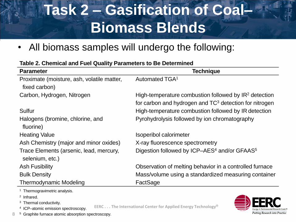
Table 2. Chemical and Fuel Quality Parameters to Be Determined
Parameter Technique
Proximate (moisture, ash, volatile matter,
fixed carbon)
Automated TGA1
Carbon, Hydrogen, Nitrogen High-temperature combustion followed by IR2 detection
for carbon and hydrogen and TC3 detection for nitrogen
Sulfur High-temperature combustion followed by IR detection
Halogens (bromine, chlorine, and
fluorine)
Pyrohydrolysis followed by ion chromatography
Heating Value Isoperibol calorimeter
Ash Chemistry (major and minor oxides) X-ray fluorescence spectrometry
Trace Elements (arsenic, lead, mercury,
selenium, etc.)
Digestion followed by ICP–AES4 and/or GFAAS5
Ash Fusibility Observation of melting behavior in a controlled furnace
Bulk Density Mass/volume using a standardized measuring container
Thermodynamic Modeling FactSage1 Thermogravimetric analysis.
2 Infrared.3 Thermal conductivity.4 ICP–atomic emission spectroscopy.5 Graphite furnace atomic absorption spectroscopy.
• All biomass samples will undergo the following:
8

EERC . . . The International Center for Applied Energy Technology
Task 3 – Analysis of Gasification
ProductsGas Analysis
Product gas can be sampled at two locations, either just after the sixth quench pot or just
after the dry gas meter. The exit gas composition is monitored with two gas analyzers.
The first is a laser gas analyzer (LGA) that is capable of detecting and measuring the
concentration of eight gases at once: H2, CO, CO2, N2, O2, H2S, CH4, and total
hydrocarbons. The LGA provides real-time feedback of the gas composition and is
typically used to aid in the control of the system. The second analyzer used is a gas
chromatograph equipped with two TC detectors and a pulsed-flame photometric detector
for ultralow sulfur detection. The first TC detector is dedicated solely to analyzing
hydrogen and provides three hydrogen measurements for each 15-minute analysis cycle.
The second detector analyzes the gas stream for CO, CO2, N2, O2, H2S, COS, CH4,
ethane, ethene, propane, and propene. One measurement is provided every 15 minutes
for each of those gases. The third detector is capable of ultralow sulfur detection, down to
50 ppb. It provides three H2S and COS measurements per 15-minute cycle.
Drager tube samples will also be taken and are used to analyze for H2S, HCl, NH3, and
HCN.
9

EERC . . . The International Center for Applied Energy Technology
Task 4 – Project Management and
Reporting
10

EERC . . . The International Center for Applied Energy Technology
Task 4 – Milestones and Schedule
ID Milestone Description
Planned
Completion Date
Actual Completion
Date
M1 Complete gasification tests 6/30/2011
M2 Complete analysis of samples 8/31/2011
M3 Draft final report 11/30/2011
M4 Final report 12/31/2011
ID2011
May DecJul NovJun
1 Task 1. System Modifications to Feed Biomass
2 Task 2. Gasification of Coal–Biomass Blends
3 Task 3. Analysis of Gasification Products
4 Task 4. Management and Reporting
Mar AugApr Sep Oct
11

EERC . . . The International Center for Applied Energy Technology
Task 4 (continued)
NDIC GE CBU
Project-Associated Expense Share Share (cash) Share (cash)
Total Direct Salaries $75,922 $13,610 $85,336
Total Fringe $40,998 $7,349 $44,923
Total Labor $116,920 $20,959 $130,259
Travel $343 – –
Equipment > $5000 – – $90,000
Supplies $4,247 $216 $3,537
Communication $63 $50 $137
Printing and Duplicating $50 $25 $125
Food – – $200
Operating Fees and Services $81,502 – $29,568
Total Direct Costs $203,125 $21,250 $253,826
Total Indirect Costs (F&A) $121,875 $12,750 $80,274
Total Project Cost $325,000 $34,000 $334,100
Labor – In addition to labor hours for the PIs, time is included for additional
engineers/operators to operate the equipment. These engineers are assigned
to the program based on an operations schedule. The exact details of which
shift engineers will be used will be determined in the weeks prior to testing.
12

EERC . . . The International Center for Applied Energy Technology
Equipment Costs
– Tubing – All tubing will be Inconel or
high-grade stainless steel.
– Injection pump – A high-pressure
injection pump will be needed to
quench the product gases.
– Fittings – Inconel high-pressure
compression fittings for corrosive
environments.
– Flanges and gaskets – Must with
stand dirty gases.
– Insulation – Custom-made Zircar
insulation sleeves for the outside of
the probe.
– Instrumentation – Control modules,
thermocouples, flow controllers for
high pressure.
– Valves and regulators – Inconel
construction, two-stage with relief.
DETAILED BUDGET – EQUIPMENT
Fabricated Equipment COST
Tubing $ 10,000
Injection Pump $ 10,000
Fittings $ 20,000
Flanges and gaskets $ 5,000
Insulation $ 15,000
Instrumentation $ 20,000
Valves and regulators $ 10,000
Total Estimated Cost: Quenched Probe $ 90,000
13
EERC . . . The International Center for Applied Energy Technology
Value to North Dakota
• Vendors of EFGs, such as GE, need these critical data in
order to move forward with projects.
• North Dakota is poised with renewable and coal
resources to be part of larger-scale renewable projects.
• Greater utilization of the biomass – higher carbon
conversion, lower tar production.
“Your proposed work using the EFG to gasify mixtures of coal and
biomass under conditions that are similar to those found in commercial
EF units will likely play an important role in the development of a coal
biomass gasification technology.”
– Gary Leonard, Global Technology Leader, GE Global Research
14

EERC . . . The International Center for Applied Energy Technology
Questions
15

EERC . . . The International Center for Applied Energy Technology
Contact Information
Energy & Environmental Research Center
University of North Dakota
15 North 23rd Street, Stop 9018
Grand Forks, North Dakota 58202-9018
World Wide Web: www.undeerc.org
Telephone No. (701) 777-5114
Fax No. (701) 777-5181
Jason Laumb, Senior Research Manager
16