biomek nx multichannel hardware manual nx... · biomek nx. • keep the biomek nx work area clear...
TRANSCRIPT

Beckman Coulter, Inc4300 N. Harbor Boulevard, Fullerton, CA 92834-3100
Copyright © 2004 Beckman Coulter, Inc. Printed in U.S.A.
Biomek® NX MultichannelLaboratory Automation
WorkstationUser’s Manual
Beckman Coulter PN 987892Revision AB
September 2004
ii
Beckman Coulter, Inc.
Except as provided in writing signed by an officer to Beckman Coulter, Inc., this system and any related documentation are provided “as is” without warranty of any kind, expressed or implied, including that the system is “error free.” This information is presented in good faith, but SAGIAN does not warrant, guarantee, or make any representations regarding the use or the results of the use of this system and related documentation in terms of correctness, accuracy, reliability, currentness, omissions, or otherwise. The entire risk as to the use, results, and performance of this system and related documentation is assumed by the user.
Except as expressly provided herein, SAGIAN makes no other warranty, whether oral or written, expressed or implied, as to any matter whatsoever, including but not limited to those concerning merchantability and fitness for a particular purpose, nor is freedom from any patent owned by SAGIAN or by others to be inferred.
LIMITATIONS OF LIABILITYSAGIAN shall not be liable, to any extent whatsoever, for any damages resulting from or arising out of the use or performance of this system and related documentation or the procedures specified in this manual, regardless of foreseeability or the form of action, whether in contract, tort (including negligence), breach of warranty, strict liability or otherwise, and including but not limited to damages resulting from loss of data, loss of anticipated profits, or any special, indirect, incidental or consequential damages. In no event shall SAGIAN’s liability to the user exceed the amount paid by the user to SAGIAN hereunder. The user assumes full responsibility for the results obtained from the use of this system and related documentation and for application of such results.
Beckman Coulter, SAGIAN OperationsIndianapolis, Indianawww.beckmancoulter.com
SILAS is a trademark and SAMI and ORCA are registered trademarks of Beckman Coulter, Inc.Microsoft and MS-DOS are registered trademarks and Windows is a trademark of Microsoft Corporation. All other trademarks appearing in this manual are owned by their respective companies.
Copyright 2004 by Beckman Coulter, Inc. All rights reserved. No part of this publication may be reproduced, distributed, or transmitted in any form or by any means, electronic, mechanical, photocopying, recording, or otherwise, or stored in a database or retrieval system, without the prior written permission of SAGIAN.
iii
Biomek® NX Multichannel Laboratory Automation Workstation User’s Manual
Warranty and Returned Goods RequirementsAll standard Beckman Coulter, Inc. policies governing returned goods apply to this product. Subject to the exceptions and upon the conditions stated below, the Company warrants that the products sold under this sales agreement shall be free from defects in workmanship and materials for one year after delivery of the products to the original Purchaser by the Company, and if any such product should prove to be defective within such one year period, the Company agrees, at its option, either (1) to correct by repair or at the Company’s election by replacement, any such defective product provided that investigation and factory inspection discloses that such defect developed under normal and proper use, or (2) to refund the purchase price. The exceptions and conditions mentioned above are as follows:
a. Components or accessories manufactured by the Company which by their nature are not intended to and will not function for one year are warranted only to reasonable service for a reasonable time. What constitutes a reasonable time and a reasonable service shall be determined solely by the Company. A complete list of such components and accessories is maintained at the factory.
b. The Company makes no warranty with respect to components or accessories not manufactured by it. In the event of defect in any such component or accessory, the Company will give reasonable assistance to Purchaser in obtaining from the manufacturer’s own warranty.
c. Any product claimed to be defective must, if required by the Company, be returned to the factory, transportation charges prepaid, and will be returned to Purchaser with transportation charges collect unless the product is found to be defective, in which case the product must be properly decontaminated of any chemical, biological, or radioactive hazardous material.
d. The Company shall be released from all obligations under all warranties, either expressed or implied, if any product covered hereby is repaired or modified by persons other than its own authorized service personnel, unless such repair by others is made with the written consent of the Company.
e. If the product is a reagent or the like, it is warranted only to conform to the quantity and content and for the period (but not in excess of one year) stated on the label at the time of delivery.
It is expressly agreed that the above warranty shall be in lieu of all warranties of fitness and of the warranty of merchantability, and that the company shall have no liability for special or consequential damages of any kind or from any cause whatsoever arising out of the manufacture, use, sale, handling, repair, maintenance, or replacement of any of the products sold under the sales agreement.
Representatives and warranties made by any person, including dealers and representatives of the Company, which are consistent or in conflict with the terms of this warranty, shall not be binding upon the Company unless reduced in writing and approved by an expressly authorized officer of the Company.
Parts replaced during the warranty period are warranted to the end of the instrument warranty.
Note: Performance characteristics and specifications are only warranted when Beckman Coulter replacement parts are used.

v
Biomek® NX Multichannel Laboratory Automation Workstation User’s Manual
Safety Information
All Warnings and Cautions in this document include an exclamation point, a lightning bolt, or a light burst symbol framed within a triangle. Please pay special attention to the specific safety information associated with these symbols.
WARNING: If the equipment is used in a manner not specified by Beckman Coulter, Inc., the protection provided by the equipment may be impaired.
Warning and Caution DefinitionsThe exclamation point symbol is an international symbol which serves as a reminder that all safety instructions should be read and understood before installation, use, maintenance, and servicing is attempted.
When this symbol is displayed in this manual, pay special attention to the specific safety information associated with the symbol.
WARNINGA WARNING calls attention to a condition or possible situation that could cause injury to the operator.
CAUTIONA CAUTION calls attention to a condition or possible situation that could damage or destroy the product or the operator’s work.
vi Safety Information
Beckman Coulter, Inc.
Electrical SafetyTo prevent electrically related injuries and property damage, properly inspect all electrical equipment prior to use and immediately report any electrical deficiencies. Contact an Beckman Coulter service representative for any servicing of equipment requiring the removal of covers or panels.
High VoltageThis symbol indicates the potential of an electrical shock hazard existing from a high voltage source and that all safety instructions should be read and understood before proceeding with the installation, maintenance, and servicing of all modules.
Do not remove system covers. To avoid electrical shock, use supplied power cords only and connect to properly grounded (three-holed) wall outlets. Do not use multiplug power strips.
Laser LightThis symbol indicates that a potential hazard to personal safety exists from a laser source. When this symbol is displayed in this manual, pay special attention to the specific safety information associated with the symbol.
Laser SpecificationsLaser Type: Class II Laser Diode
Maximum Output:11 mW
Wavelength: 670
Safety Information vii
Biomek® NX Multichannel Laboratory Automation Workstation User’s Manual
Chemical and Biological SafetyNormal operation of the Biomek NX may involve the use of materials that are toxic, flammable, or otherwise biologically harmful. When using such materials, observe the following precautions:
• Handle infectious samples according to good laboratory procedures and methods to prevent the spread of disease.
• Observe all cautionary information printed on the original solutions containers prior to their use.
• Dispose of all waste solutions according to your facility’s waste disposal procedures.
• Operate the Biomek NX in accordance with the instructions outlined in this manual, and take all the necessary precautions when using pathological, toxic, or radioactive materials.
• Splashing of liquids may occur; therefore, take appropriate safety precautions, such as using safety glasses and wearing protective clothing, when working with potentially hazardous liquids.
• Use an appropriately contained environment when using hazardous materials.
• Observe the appropriate cautionary procedures as defined by your safety officer when using flammable solvents in or near a powered-up instrument.
• Observe the appropriate cautionary procedures as defined by your safety officer when using toxic, pathological, or radioactive materials.
Note: Observe all warnings and cautions listed for any external devices attached or used during operation of the Biomek NX. Refer to applicable external device user’s manuals for operating procedures of that device.
viii Safety Information
Beckman Coulter, Inc.
Moving PartsTo avoid injury due to moving parts, observe the following:
• Never attempt to exchange labware, reagents, or tools while the instrument is operating.
• Never attempt to physically restrict any of the moving components of the Biomek NX.
• Keep the Biomek NX work area clear to prevent obstruction of the movement.
CleaningObserve the cleaning procedures outlined in this user’s manual for the Biomek NX. Prior to cleaning equipment that has been exposed to hazardous material:
• Appropriate Chemical and Biological Safety personnel should be contacted.
• The Chemical and Biological Safety information contained in this user’s manual should be reviewed.
MaintenancePerform only the maintenance described in this manual. Maintenance other than that specified in this manual should be performed only by Beckman Coulter service representatives.
It is your responsibility to decontaminate components of the Biomek NX before requesting service by a Beckman Coulter service representative or returning parts to Beckman Coulter for repair. Beckman Coulter will NOT accept any items which have not been decontaminated where it is appropriate to do so. If any parts are returned, they must be enclosed in a sealed plastic bag stating that the contents are safe to handle and are not contaminated.
Important
Safety Information ix
Biomek® NX Multichannel Laboratory Automation Workstation User’s Manual
Warnings and Cautions Found in this ManualPlease read and observe all cautions and instructions. Remember, the most important key to safety is to operate the Biomek NX with care.
The WARNINGs and CAUTIONs found within this document are listed below.
WARNING: If the equipment is used in a manner not specified by Beckman Coulter, Inc., the protection provided by the equipment may be impaired.
WARNING: Dark non-reflective material affects the sensitivity of the light curtain and adversely impact its effectiveness. Typical lab dress, such as lab coats and latex gloves, do not degrade light curtain operation; however, it is advisable to test the impact of the all lab dress on light curtain sensitivity before operating the Biomek NX. Verify lab dress impact on light curtain sensitivity as follows: Use Manual Control in Biomek Software and insert the material no more than 1” past and approximately 21” above the light curtain panel. Make sure the solid amber indicator light changes to blinking amber.
WARNING: To reduce the risk of personal injury, operate the Biomek NX instrument only with all protective shields in place.
WARNING: To prevent injury, use proper decontamination procedures.
CAUTION: If service is required, contact a Beckman Coulter Service Engineer.
WARNING: Do not remove tower covers to access electrical wiring or fuses. Change only the fuses that are accessed from the outside of the instrument, without removing covers. Contact a Beckman Coulter Service Engineer if further access is required.
WARNING: Turn off and unplug power to the instrument before changing fuses. Failure to do so can cause electrical shock or equipment damage.
CAUTION: To prevent damage due to electrical static discharge (ESD), wear a wrist ground strap when handling a multichannel head.
CAUTION: Before removing the fourth shoulder screw, take hold of the head firmly to make sure it does not fall once all screws are removed.
WARNING: The gripper may bend if not taught (framed) properly with the AccuFrame.
WARNING: Do not connect or disconnect any cable while power is applied to the Biomek NX.
WARNING: Avoid all labware on the Biomek NX deck when removing or installing grippers. It is recommended that all labware in the vicinity of the pod be moved or removed to avoid spills and contact with labware.
x Safety Information
Beckman Coulter, Inc.
CAUTION: Use caution when removing gripper fingers. Since gripper fingers mount tightly into the Multichannel Pod, they pull free of the Multichannel Pod suddenly.
CAUTION: Do not make any changes to the pod axes limits in Hardware Setup without contacting a Beckman Coulter Service Engineer or Beckman Coulter Customer Technical Support.
CAUTION: If the hardware configuration is not updated using Hardware Setup, hardware crashes or inaccurate liquid transfer may occur.
CAUTION: To avoid hardware crashes, a new D-axis limit must be established and the gripper framed in the Biomek Software after the head has been configured in Hardware Setup.
CAUTION: Always ensure that the gripper is retracted before homing.
CAUTION: Before selecting OK to home all axes, the following conditions must be met:
• Make sure there is no liquid present in the tips
• Make sure there are no disposable tips loaded
• Make sure the Framing Probe is NOT installed on the Multichannel Pod.
• Make sure the gripper on the Multichannel Pod is retracted.
WARNING: Turn off power to the Biomek NX instrument before attaching or removing AccuFrame from the instrument deck.
WARNING: Make sure the light curtain is not violated by the AccuFrame cable. If the light curtain is violated, the framing process halts immediately.
WARNING: Make sure the AccuFrame cable does not interfere with pod movement.
CAUTION: Use Shift deck only before other ALPs or positions are taught. Shift deck shifts all ALPs and positions, resulting in incorrect coordinates if applied to previously framed ALPs and positions.
CAUTION: Select Move Z-Max to move the pod to its highest point before extending the gripper. To avoid breaking labware or bending the gripper fingers, make sure the gripper fingers will not hit any labware when extended.
CAUTION: Do not retract gripper when it is holding labware.
WARNING: CLASS II LASER PRODUCT
THIS PRODUCT CONFORMS TO APPLICABLE REQUIREMENTS OF 21 CFR 1040 AT THE DATE OF MANUFACTURE.
Safety Information xi
Biomek® NX Multichannel Laboratory Automation Workstation User’s Manual
CAUTION: To avoid serious damage to the instrument, make sure that the laboratory site voltage/frequency matches the voltage/frequency that was ordered for the instrument.
WARNING: Do not attempt to remove or replace covers while the unit is powered on. Disconnect power before removing or replacing a cover.
WARNING: Avoid direct exposure to the laser beam. Never look directly into the laser beam, and never leave the laser on, open, or unattended.
WARNING: Always have the laser module access cover, located on the bar code reader, in place when operating or troubleshooting the laser module.
CAUTION: If labware other than that specified in the Stacker Carousel User’s Manual is used, an increase in bad reads or no reads may occur.
CAUTION: If a label is applied by any means other than the Beckman Coulter Print and Apply device, an increase in bad reads or no reads may occur.
CAUTION: To prevent damage to the shuttle, first place the AccuFrame into the Framing Tool Adaptor. Then place the AccuFrame with the attached adaptor on the shuttle.

xiii
Biomek® NX Multichannel Laboratory Automation Workstation User’s Manual
Table of Contents
Warranty and Returned Goods Requirements . . . . . . . . . . . . . . . . . . . . . . . . . . . . . . . . . . . iii
Safety Information . . . . . . . . . . . . . . . . . . . . . . . . . . . . . . . . . . . . . . . . . . vWarning and Caution Definitions . . . . . . . . . . . . . . . . . . . . . . . . . . . . . . . . . . . . . . . . . . . . . vElectrical Safety . . . . . . . . . . . . . . . . . . . . . . . . . . . . . . . . . . . . . . . . . . . . . . . . . . . . . . . . . . vi
High Voltage. . . . . . . . . . . . . . . . . . . . . . . . . . . . . . . . . . . . . . . . . . . . . . . . . . . . . . . . viLaser Light . . . . . . . . . . . . . . . . . . . . . . . . . . . . . . . . . . . . . . . . . . . . . . . . . . . . . . . . . . . . . . vi
Laser Specifications . . . . . . . . . . . . . . . . . . . . . . . . . . . . . . . . . . . . . . . . . . . . . . . . . . viChemical and Biological Safety . . . . . . . . . . . . . . . . . . . . . . . . . . . . . . . . . . . . . . . . . . . . . viiMoving Parts . . . . . . . . . . . . . . . . . . . . . . . . . . . . . . . . . . . . . . . . . . . . . . . . . . . . . . . . . . . viiiCleaning . . . . . . . . . . . . . . . . . . . . . . . . . . . . . . . . . . . . . . . . . . . . . . . . . . . . . . . . . . . . . . . viiiMaintenance. . . . . . . . . . . . . . . . . . . . . . . . . . . . . . . . . . . . . . . . . . . . . . . . . . . . . . . . . . . . viiiWarnings and Cautions Found in this Manual. . . . . . . . . . . . . . . . . . . . . . . . . . . . . . . . . . . ix
Table of Contents . . . . . . . . . . . . . . . . . . . . . . . . . . . . . . . . . . . . . . . . . . xiii
List of Figures . . . . . . . . . . . . . . . . . . . . . . . . . . . . . . . . . . . . . . . . . . . . xvii
List of Tables. . . . . . . . . . . . . . . . . . . . . . . . . . . . . . . . . . . . . . . . . . . . . . xxi
1 Biomek® NX Multichannel Introduction1.1 Instrument Overview . . . . . . . . . . . . . . . . . . . . . . . . . . . . . . . . . . . . . . . . . . . . . . . 1-1
1.1.1 Control Modes . . . . . . . . . . . . . . . . . . . . . . . . . . . . . . . . . . . . . . . . . . . . 1-11.2 System Components . . . . . . . . . . . . . . . . . . . . . . . . . . . . . . . . . . . . . . . . . . . . . . . 1-2
1.2.1 Towers . . . . . . . . . . . . . . . . . . . . . . . . . . . . . . . . . . . . . . . . . . . . . . . . . . 1-31.2.2 Multichannel Pod . . . . . . . . . . . . . . . . . . . . . . . . . . . . . . . . . . . . . . . . . . 1-51.2.3 Deck . . . . . . . . . . . . . . . . . . . . . . . . . . . . . . . . . . . . . . . . . . . . . . . . . . . . 1-51.2.4 Protective Barriers . . . . . . . . . . . . . . . . . . . . . . . . . . . . . . . . . . . . . . . . . 1-7
1.3 Preventive Maintenance. . . . . . . . . . . . . . . . . . . . . . . . . . . . . . . . . . . . . . . . . . . . . 1-91.3.1 Light Curtain Maintenance . . . . . . . . . . . . . . . . . . . . . . . . . . . . . . . . . . . 1-9
1.4 Troubleshooting . . . . . . . . . . . . . . . . . . . . . . . . . . . . . . . . . . . . . . . . . . . . . . . . . . 1-101.4.1 Changing Fuses. . . . . . . . . . . . . . . . . . . . . . . . . . . . . . . . . . . . . . . . . . . 1-11
xiv Table of Contents
Beckman Coulter, Inc.
2 Multichannel Pod2.1 Overview . . . . . . . . . . . . . . . . . . . . . . . . . . . . . . . . . . . . . . . . . . . . . . . . . . . . . . . . 2-1
2.1.1 Main Components of the Multichannel Pod . . . . . . . . . . . . . . . . . . . . . . 2-32.1.2 Pod Movements . . . . . . . . . . . . . . . . . . . . . . . . . . . . . . . . . . . . . . . . . . . 2-42.1.3 Control Modes . . . . . . . . . . . . . . . . . . . . . . . . . . . . . . . . . . . . . . . . . . . . 2-4
2.2 Interchangeable Heads . . . . . . . . . . . . . . . . . . . . . . . . . . . . . . . . . . . . . . . . . . . . . . 2-52.2.1 Changing Heads . . . . . . . . . . . . . . . . . . . . . . . . . . . . . . . . . . . . . . . . . . . 2-5
2.3 Gripper . . . . . . . . . . . . . . . . . . . . . . . . . . . . . . . . . . . . . . . . . . . . . . . . . . . . . . . . . 2-122.3.1 Framing the Gripper . . . . . . . . . . . . . . . . . . . . . . . . . . . . . . . . . . . . . . . 2-13
2.4 Preventive Maintenance. . . . . . . . . . . . . . . . . . . . . . . . . . . . . . . . . . . . . . . . . . . . 2-142.5 Troubleshooting . . . . . . . . . . . . . . . . . . . . . . . . . . . . . . . . . . . . . . . . . . . . . . . . . . 2-15
2.5.1 Replacing Gripper Fingers . . . . . . . . . . . . . . . . . . . . . . . . . . . . . . . . . . 2-16
3 Configuring the Biomek® NX Multichannel in Biomek Software3.1 Overview . . . . . . . . . . . . . . . . . . . . . . . . . . . . . . . . . . . . . . . . . . . . . . . . . . . . . . . . 3-1
3.1.1 Accessing Hardware Setup . . . . . . . . . . . . . . . . . . . . . . . . . . . . . . . . . . . 3-23.1.2 Understanding the Options in Hardware Setup . . . . . . . . . . . . . . . . . . . 3-3
3.2 Configuring the Biomek NX Multichannel Instrument . . . . . . . . . . . . . . . . . . . . . 3-43.3 Configuring a Multichannel Pod . . . . . . . . . . . . . . . . . . . . . . . . . . . . . . . . . . . . . . 3-5
3.3.1 Configuring a New Head . . . . . . . . . . . . . . . . . . . . . . . . . . . . . . . . . . . . 3-53.3.2 Setting Multichannel Pod Properties . . . . . . . . . . . . . . . . . . . . . . . . . . . 3-7
3.4 Saving, Restoring, and Deleting Settings . . . . . . . . . . . . . . . . . . . . . . . . . . . . . . 3-103.4.1 Saving Pod Settings . . . . . . . . . . . . . . . . . . . . . . . . . . . . . . . . . . . . . . . 3-103.4.2 Restoring Pod Settings . . . . . . . . . . . . . . . . . . . . . . . . . . . . . . . . . . . . . 3-113.4.3 Deleting Pod Settings . . . . . . . . . . . . . . . . . . . . . . . . . . . . . . . . . . . . . . 3-12
4 Framing Instructions 4.1 Overview . . . . . . . . . . . . . . . . . . . . . . . . . . . . . . . . . . . . . . . . . . . . . . . . . . . . . . . . 4-14.2 Framing Deck Positions on the Biomek® NX Using AccuFrame . . . . . . . . . . . . 4-2
4.2.1 Homing All Axes of the Pods . . . . . . . . . . . . . . . . . . . . . . . . . . . . . . . . . 4-34.2.2 Attaching the Framing Fixture to the Pod . . . . . . . . . . . . . . . . . . . . . . . 4-54.2.3 Installing AccuFrame . . . . . . . . . . . . . . . . . . . . . . . . . . . . . . . . . . . . . . . 4-64.2.4 Framing the Position. . . . . . . . . . . . . . . . . . . . . . . . . . . . . . . . . . . . . . . . 4-7
4.3 Manually Framing Deck Positions on the Biomek® NX . . . . . . . . . . . . . . . . . . 4-114.3.1 Using the Graphic Alignment Tool . . . . . . . . . . . . . . . . . . . . . . . . . . . 4-154.3.2 Using the Delta Value and Directional Buttons . . . . . . . . . . . . . . . . . . 4-174.3.3 Framing the Z-Axis. . . . . . . . . . . . . . . . . . . . . . . . . . . . . . . . . . . . . . . . 4-19
4.4 Framing the Gripper . . . . . . . . . . . . . . . . . . . . . . . . . . . . . . . . . . . . . . . . . . . . . . 4-214.4.1 Testing Gripper Framing Accuracy . . . . . . . . . . . . . . . . . . . . . . . . . . . 4-25
4.5 Troubleshooting . . . . . . . . . . . . . . . . . . . . . . . . . . . . . . . . . . . . . . . . . . . . . . . . . . 4-26
Table of Contents xv
Biomek® NX Multichannel Laboratory Automation Workstation User’s Manual
5 Manually Controlling the Biomek® NX in Biomek Software5.1 Overview . . . . . . . . . . . . . . . . . . . . . . . . . . . . . . . . . . . . . . . . . . . . . . . . . . . . . . . . 5-15.2 Accessing Manual Control. . . . . . . . . . . . . . . . . . . . . . . . . . . . . . . . . . . . . . . . . . . 5-25.3 Using Manual Control . . . . . . . . . . . . . . . . . . . . . . . . . . . . . . . . . . . . . . . . . . . . . . 5-3
5.3.1 Homing all Axes of the Pod . . . . . . . . . . . . . . . . . . . . . . . . . . . . . . . . . . 5-35.3.2 Moving the Pod to a Specific Deck Position . . . . . . . . . . . . . . . . . . . . . 5-45.3.3 Stopping the Pod. . . . . . . . . . . . . . . . . . . . . . . . . . . . . . . . . . . . . . . . . . . 5-45.3.4 Viewing the Firmware Version. . . . . . . . . . . . . . . . . . . . . . . . . . . . . . . . 5-45.3.5 Accessing Advanced Manual Control . . . . . . . . . . . . . . . . . . . . . . . . . . 5-4
5.4 Using Advanced Manual Control . . . . . . . . . . . . . . . . . . . . . . . . . . . . . . . . . . . . . 5-55.4.1 Viewing the Current Position of the Pod . . . . . . . . . . . . . . . . . . . . . . . . 5-75.4.2 Moving the Pod to a Safe Roving Height . . . . . . . . . . . . . . . . . . . . . . . . 5-75.4.3 Performing Relative Moves for the Pod . . . . . . . . . . . . . . . . . . . . . . . . . 5-75.4.4 Performing Absolute Moves for the Pod . . . . . . . . . . . . . . . . . . . . . . . 5-105.4.5 Extending and Retracting the Gripper . . . . . . . . . . . . . . . . . . . . . . . . . 5-11
Appendix A: Specifications . . . . . . . . . . . . . . . . . . . . . . . . . . . . . . . . . .A-1
Appendix B: Using a Stacker Carousel . . . . . . . . . . . . . . . . . . . . . . . .B-1B.1 Overview. . . . . . . . . . . . . . . . . . . . . . . . . . . . . . . . . . . . . . . . . . . . . . . . . . . . . . . . . . B-1B.2 Integrating the Stacker Carousel. . . . . . . . . . . . . . . . . . . . . . . . . . . . . . . . . . . . . . . . B-2
B.2.1 Positioning the Stacker Carousel on the Deck. . . . . . . . . . . . . . . . . . . . . . B-3B.2.2 Mounting the Stacker Carousel . . . . . . . . . . . . . . . . . . . . . . . . . . . . . . . . . B-5B.2.3 Attaching the Side Shield . . . . . . . . . . . . . . . . . . . . . . . . . . . . . . . . . . . . . B-8B.2.4 Operating the Stacker Carousel . . . . . . . . . . . . . . . . . . . . . . . . . . . . . . . . B-10B.2.5 Preventive Maintenance and Troubleshooting . . . . . . . . . . . . . . . . . . . . B-10
B.3 Integrating the Bar Code Reader . . . . . . . . . . . . . . . . . . . . . . . . . . . . . . . . . . . . . . B-11B.3.1 Attaching Bar Code Reader Bracket . . . . . . . . . . . . . . . . . . . . . . . . . . . . B-11B.3.2 Attaching Bar Code Reader to Shuttle. . . . . . . . . . . . . . . . . . . . . . . . . . . B-12B.3.3 Positioning Bar Code Reader. . . . . . . . . . . . . . . . . . . . . . . . . . . . . . . . . . B-14B.3.4 Applying Power to the Bar Code Reader. . . . . . . . . . . . . . . . . . . . . . . . . B-20B.3.5 Aligning the Laser Beam . . . . . . . . . . . . . . . . . . . . . . . . . . . . . . . . . . . . . B-20
B.4 Configuring the Stacker Carousel in Hardware Setup . . . . . . . . . . . . . . . . . . . . . . B-23B.4.1 Installing Stacker Carousels. . . . . . . . . . . . . . . . . . . . . . . . . . . . . . . . . . . B-23B.4.2 Configuring Stacker Carousels . . . . . . . . . . . . . . . . . . . . . . . . . . . . . . . . B-25B.4.3 Removing Stacker Carousels . . . . . . . . . . . . . . . . . . . . . . . . . . . . . . . . . . B-26
B.5 Framing the Stacker Carousel. . . . . . . . . . . . . . . . . . . . . . . . . . . . . . . . . . . . . . . . . B-27
Index. . . . . . . . . . . . . . . . . . . . . . . . . . . . . . . . . . . . . . . . . . . . . . . . . . . . xxiii

xvii
Biomek® NX Multichannel Laboratory Automation Workstation User’s Manual
List of Figures
Figure 1-1. Biomek NX with Multichannel Pod.......................................................................... 1-2Figure 1-2. Right tower outside ................................................................................................... 1-3Figure 1-3. Left tower outside ..................................................................................................... 1-4Figure 1-4. Right tower inside ..................................................................................................... 1-4Figure 1-5. Protective barriers for the Biomek NX Instrument ................................................... 1-7Figure 1-6. Replacing fuses in tower ......................................................................................... 1-12Figure 2-1. Multichannel Pod installed on Biomek NX .............................................................. 2-2Figure 2-2. Multichannel Pod — main components.................................................................... 2-3Figure 2-3. Wrist ground strap attached to the deck.................................................................... 2-6Figure 2-4. Bottom cover removed from the pod ........................................................................ 2-7Figure 2-5. Plunger screws and shoulder screws removed from multichannel head................... 2-8Figure 2-6. Sequence for removing four plunger screws and four shoulder screws on all
multichannel heads .............................................................................................. 2-9Figure 2-7. Chamfer location on a Multichannel head .............................................................. 2-10Figure 2-8. Sequence for installing four plunger screws and four shoulder screws on all
multichannel heads ............................................................................................ 2-10Figure 2-9. Grippers................................................................................................................... 2-12Figure 2-10. Removable front gripper assembly ....................................................................... 2-17Figure 3-1. Hardware Setup for a Biomek NX Multichannel instrument.................................... 3-2Figure 3-2. Hardware Setup showing the configuration of a Multichannel Pod ......................... 3-6Figure 3-3. Warnings must be addressed before homing process begins .................................... 3-6Figure 3-4. Hardware Setup displaying Enable Plate Sensor ...................................................... 3-9Figure 3-5. Error for no plate sensed ........................................................................................... 3-9Figure 3-6. Save Configuration ................................................................................................. 3-10Figure 3-7. Load Settings........................................................................................................... 3-11Figure 3-8. Confirmation to reset stored configuration ............................................................. 3-11Figure 3-9. Delete Settings ........................................................................................................ 3-12Figure 3-10. Confirmation to delete stored configuration ......................................................... 3-12Figure 4-1. AccuFrame framing tool ........................................................................................... 4-2Figure 4-2. Warning to address before homing process begins................................................... 4-4Figure 4-3. Framing Fixture......................................................................................................... 4-5
xviii List of Figures
Beckman Coulter, Inc.
Figure 4-4. Deck Editor ............................................................................................................... 4-7Figure 4-5. Position Properties .................................................................................................... 4-8Figure 4-6. Confirm ..................................................................................................................... 4-8Figure 4-7. Teaching Instructions ................................................................................................ 4-9Figure 4-8. Deck Editor ............................................................................................................. 4-11Figure 4-9. Position Properties for a Positive Position ALP ..................................................... 4-12Figure 4-10. Manual Framing Wizard — Warning ................................................................... 4-12Figure 4-11. Manual Framing Wizard if tips are not already loaded......................................... 4-13Figure 4-12. Manual Framing Wizard if tips are loaded ........................................................... 4-13Figure 4-13. Framing to the corner of four wells ...................................................................... 4-14Figure 4-14. Framing to the center of a well ............................................................................. 4-14Figure 4-15. Manual Teaching the X- and Y-axes .................................................................... 4-15Figure 4-16. Manual Teaching the X- and Y-axes .................................................................... 4-17Figure 4-17. Manual Teaching (Teach Z).................................................................................. 4-19Figure 4-18. Hardware Setup..................................................................................................... 4-21Figure 4-19. Warning to make sure gripper is ready for framing.............................................. 4-22Figure 4-20. Pick previously framed deck position to frame the grippers................................. 4-22Figure 4-21. Advanced Manual Control for moving gripper during framing............................ 4-23Figure 4-22. Moving pod into gripping position ....................................................................... 4-23Figure 4-23. Gripper framing position on the AccuFrame ........................................................ 4-24Figure 4-24. Correct and incorrect gripper framing alignment.................................................. 4-24Figure 5-1. Confirms Manual Control is connecting ................................................................... 5-2Figure 5-2. Manual Control ......................................................................................................... 5-2Figure 5-3. Warnings must be addressed before homing process begins .................................... 5-3Figure 5-4. Firmware version information .................................................................................. 5-4Figure 5-5. Overview Advanced Manual Control for a Multichannel Pod ................................. 5-5Figure 5-6. Vector Builder........................................................................................................... 5-9Figure 5-7. Enter Absolute Move Coordinates .......................................................................... 5-10Figure B-1. Stacker Carousel.......................................................................................................B-2Figure B-2. Stacker shuttle positions ...........................................................................................B-3Figure B-3. Stacker Carousel integration ....................................................................................B-4Figure B-4. Attaching alignment bracket ....................................................................................B-5Figure B-5. Attaching riser plate .................................................................................................B-6Figure B-6. Stacker attachment ...................................................................................................B-7Figure B-7. Attaching the side shield components to Biomek NX .............................................B-8Figure B-8. Aligning the stack carousel shuttle...........................................................................B-9Figure B-9. Front view of stacker integration..............................................................................B-9Figure B-10. Stacker Carousel final placement (top view rear position, right side) .................B-10Figure B-11. Bar code reader bracket ........................................................................................B-11Figure B-12. Bar code reader shuttle mount access cover removed..........................................B-12Figure B-13. Mounting bracket attachment ...............................................................................B-12Figure B-14. Mounting bar code reader.....................................................................................B-13Figure B-15. Bar code reader in narrow side scanning position................................................B-14Figure B-16. Bar code reader in narrow side scanning position................................................B-15Figure B-17. Bar code reader in wide right side scanning position...........................................B-15Figure B-18. Bar code reader in wide right side scanning position (bottom view) ...................B-16
List of Figures xix
Biomek® NX Multichannel Laboratory Automation Workstation User’s Manual
Figure B-19. Bar code reader in rear narrow side scanning position.........................................B-16Figure B-20. Bar code reader in rear narrow side scanning position (bottom view).................B-17Figure B-21. Bar code reader in wide left side scanning position .............................................B-17Figure B-22. Bar code reader in wide left side scanning position (bottom view) .....................B-18Figure B-23. Bar code reader in front narrow side scanning position .......................................B-18Figure B-24. Bar code reader in front narrow side scanning position (bottom view) ...............B-19Figure B-25. Bar code reader attachment bracket .....................................................................B-19Figure B-26. Bar code reader — Laser beam position over bar code label...............................B-21Figure B-27. Adjust laser alignment as necessary .....................................................................B-21Figure B-28. Label positioning on microplate...........................................................................B-22Figure B-29. New Devices.........................................................................................................B-23Figure B-30. Installing a Stacker Carousel by right-clicking ....................................................B-24Figure B-31. Hardware Setup showing the configuration view for a Stacker Carousel............B-25Figure B-32. Adding the Accuframe and Framing Tool Adaptor
to the Stacker Carousel shuttle...........................................................................B-28

xxi
Biomek® NX Multichannel Laboratory Automation Workstation User’s Manual
List of Tables
Table 1-1. Indicator Light Key .................................................................................................... 1-5Table 1-2. Troubleshooting the Biomek NX Instrument ........................................................... 1-10Table 2-1. Multichannel Pod Axes Movement ............................................................................ 2-4Table 2-2. Tip compatibility and max volumes on Multichannel Heads..................................... 2-5Table 2-3. Multichannel Pod Troubleshooting .......................................................................... 2-15Table 3-1. Hardware Setup Options ............................................................................................ 3-3Table 3-2. Multichannel Pod Properties ...................................................................................... 3-7Table 4-1. Troubleshooting Framing ......................................................................................... 4-26Table 5-1. Advanced Manual Control selection areas for the Multichannel Pod........................ 5-6Table A-1. System Specifications............................................................................................... A-1

1-1
Biomek® NX Multichannel Laboratory Automation Workstation User’s Manual
1 Biomek® NX Multichannel Introduction
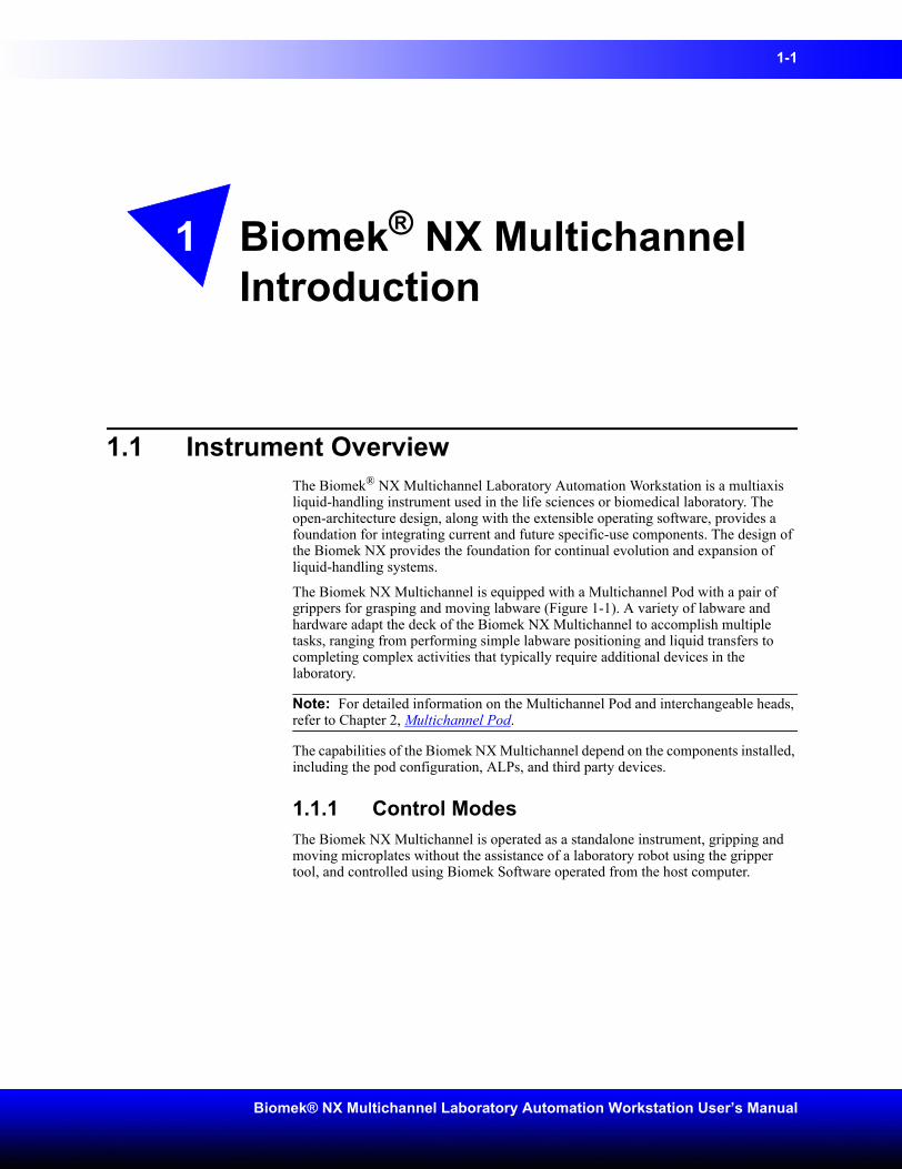
1.1 Instrument OverviewThe Biomek® NX Multichannel Laboratory Automation Workstation is a multiaxis liquid-handling instrument used in the life sciences or biomedical laboratory. The open-architecture design, along with the extensible operating software, provides a foundation for integrating current and future specific-use components. The design of the Biomek NX provides the foundation for continual evolution and expansion of liquid-handling systems.
The Biomek NX Multichannel is equipped with a Multichannel Pod with a pair of grippers for grasping and moving labware (Figure 1-1). A variety of labware and hardware adapt the deck of the Biomek NX Multichannel to accomplish multiple tasks, ranging from performing simple labware positioning and liquid transfers to completing complex activities that typically require additional devices in the laboratory.
Note: For detailed information on the Multichannel Pod and interchangeable heads, refer to Chapter 2, Multichannel Pod.
The capabilities of the Biomek NX Multichannel depend on the components installed, including the pod configuration, ALPs, and third party devices.
1.1.1 Control ModesThe Biomek NX Multichannel is operated as a standalone instrument, gripping and moving microplates without the assistance of a laboratory robot using the gripper tool, and controlled using Biomek Software operated from the host computer.
1-2 Biomek® NX Multichannel Introduction
Beckman Coulter, Inc.
1.2 System ComponentsThe system components described below correspond to the configurations in Figure 1-1.
Figure 1-1. Biomek NX with Multichannel Pod
Multichannel Pod with gripper tool
Deck
Towers
Biomek® NX Multichannel Introduction 1-3
Biomek® NX Multichannel Laboratory Automation Workstation User’s Manual
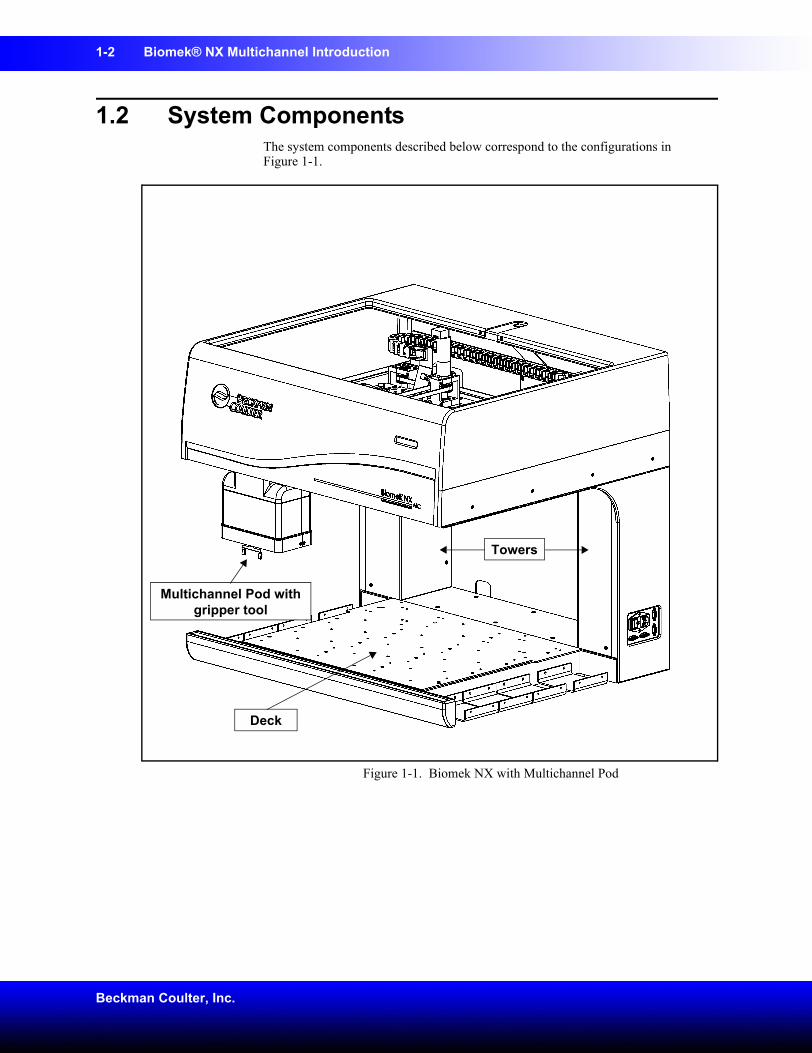
1.2.1 TowersThe Biomek NX Multichannel towers (Figure 1-1) form the two upright sections of the base unit along which the pod travels on the X-axis. The host computer connection of the Biomek NX system, plus utility hook-ups and ALP connections, are located on the towers. A status indicator panel with green and amber indicator lights is built into the main cover and keep users aware of the current operational status of the (refer to Section 1.2.1.1, Indicator Lights).
The towers house the following connections:
• Main power switch on the outside of the right tower (Figure 1-2).
• Communication hookup to host computer via RS232 on the outside of the right tower.
• Main power fuses for the instrument on the outside of the right tower.
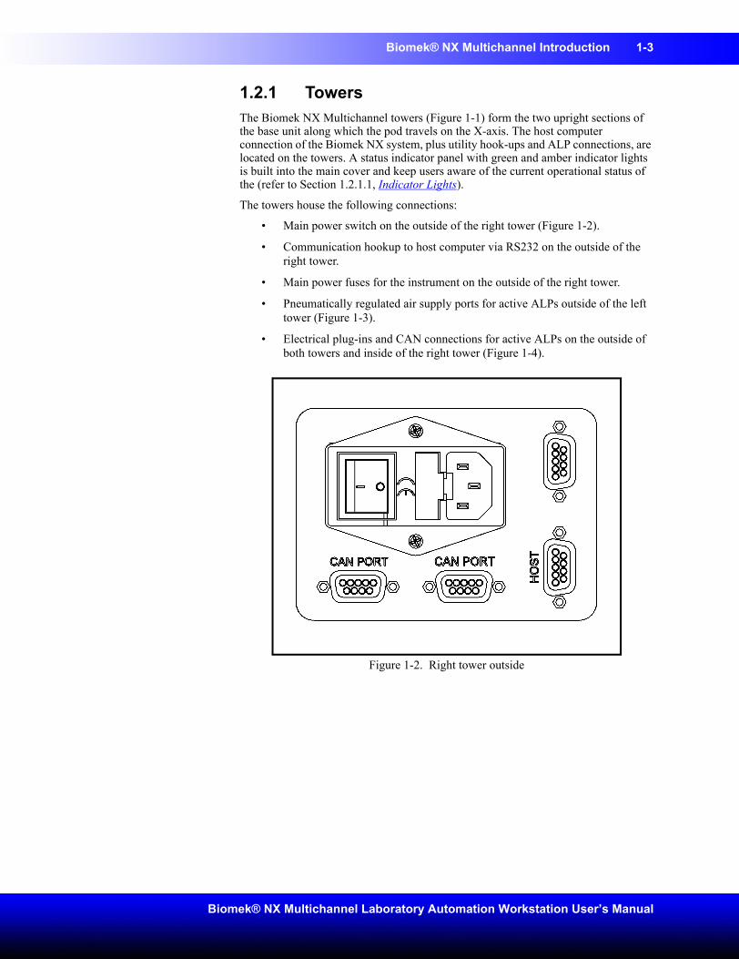
• Pneumatically regulated air supply ports for active ALPs outside of the left tower (Figure 1-3).
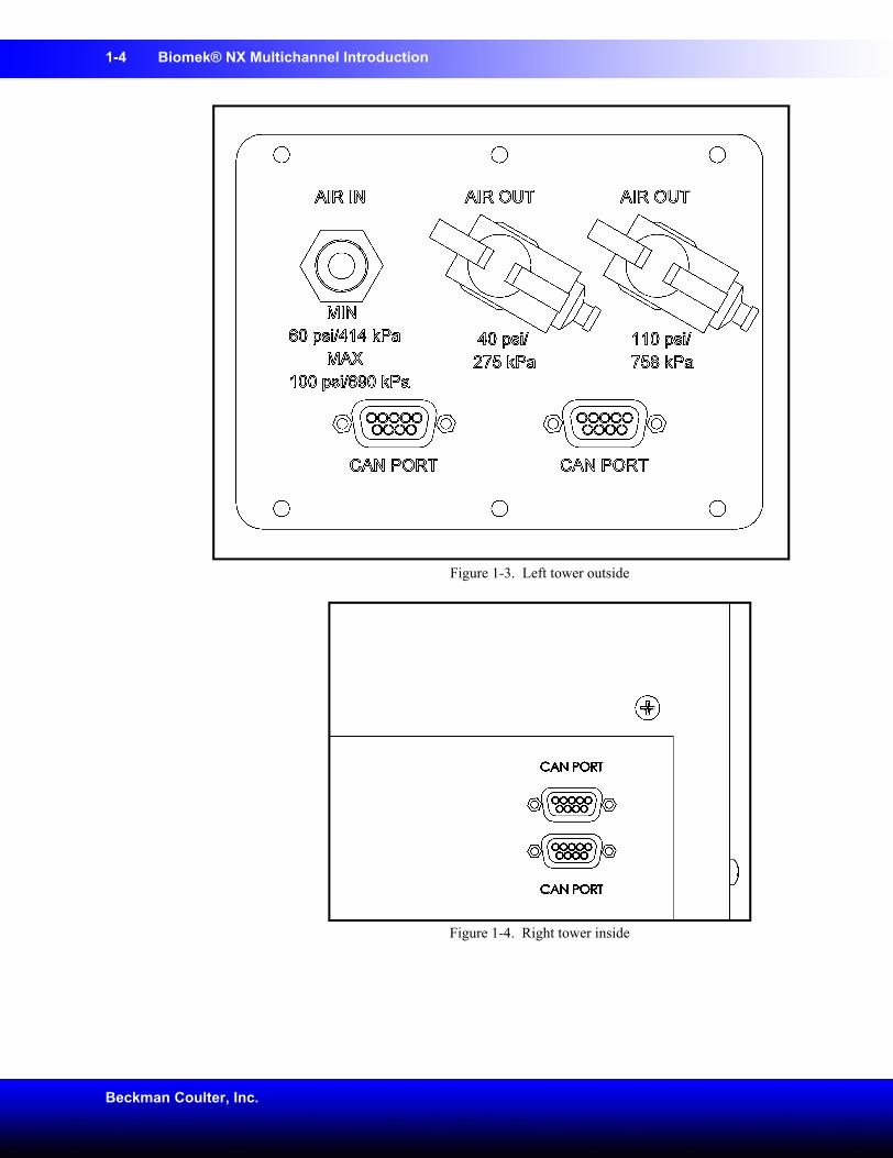
• Electrical plug-ins and CAN connections for active ALPs on the outside of both towers and inside of the right tower (Figure 1-4).
Figure 1-2. Right tower outside
1-4 Biomek® NX Multichannel Introduction
Beckman Coulter, Inc.
Figure 1-3. Left tower outside
Figure 1-4. Right tower inside
Biomek® NX Multichannel Introduction 1-5
Biomek® NX Multichannel Laboratory Automation Workstation User’s Manual
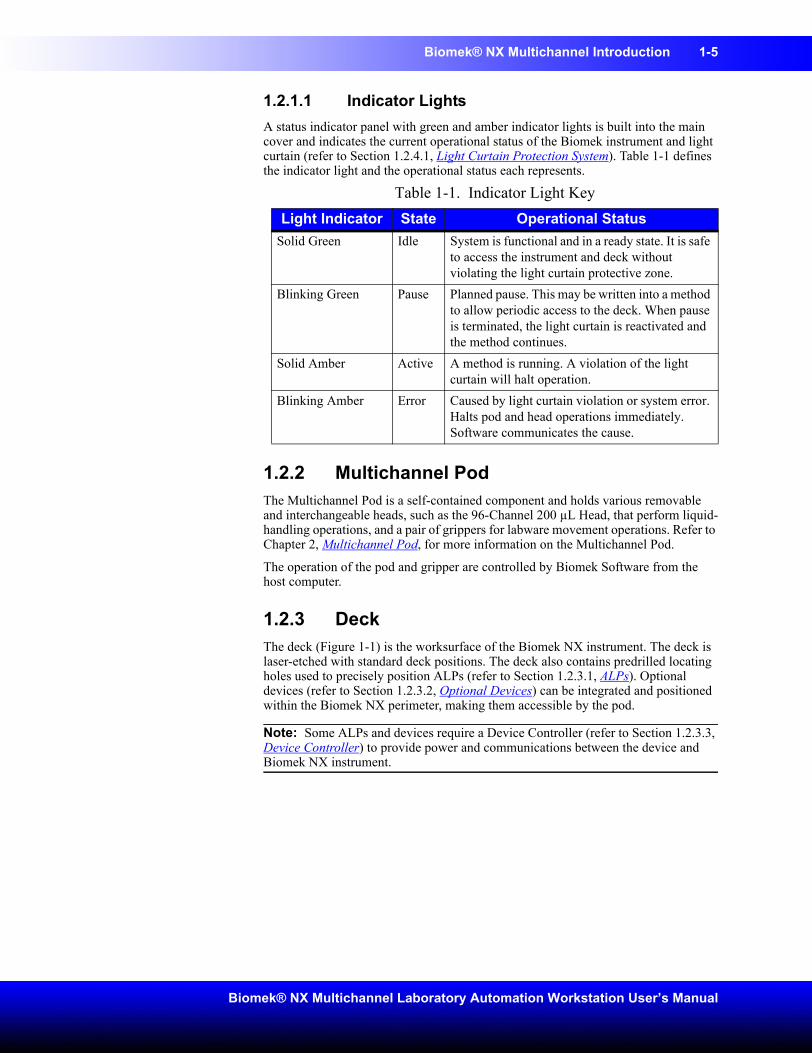
1.2.1.1 Indicator LightsA status indicator panel with green and amber indicator lights is built into the main cover and indicates the current operational status of the Biomek instrument and light curtain (refer to Section 1.2.4.1, Light Curtain Protection System). Table 1-1 defines the indicator light and the operational status each represents.
1.2.2 Multichannel PodThe Multichannel Pod is a self-contained component and holds various removable and interchangeable heads, such as the 96-Channel 200 µL Head, that perform liquid-handling operations, and a pair of grippers for labware movement operations. Refer to Chapter 2, Multichannel Pod, for more information on the Multichannel Pod.
The operation of the pod and gripper are controlled by Biomek Software from the host computer.
1.2.3 DeckThe deck (Figure 1-1) is the worksurface of the Biomek NX instrument. The deck is laser-etched with standard deck positions. The deck also contains predrilled locating holes used to precisely position ALPs (refer to Section 1.2.3.1, ALPs). Optional devices (refer to Section 1.2.3.2, Optional Devices) can be integrated and positioned within the Biomek NX perimeter, making them accessible by the pod.
Note: Some ALPs and devices require a Device Controller (refer to Section 1.2.3.3, Device Controller) to provide power and communications between the device and Biomek NX instrument.
Table 1-1. Indicator Light KeyLight Indicator State Operational Status
Solid Green Idle System is functional and in a ready state. It is safe to access the instrument and deck without violating the light curtain protective zone.
Blinking Green Pause Planned pause. This may be written into a method to allow periodic access to the deck. When pause is terminated, the light curtain is reactivated and the method continues.
Solid Amber Active A method is running. A violation of the light curtain will halt operation.
Blinking Amber Error Caused by light curtain violation or system error. Halts pod and head operations immediately. Software communicates the cause.
1-6 Biomek® NX Multichannel Introduction
Beckman Coulter, Inc.
1.2.3.1 ALPsAutomated Labware Positioners (ALPs) are interchangeable structures that are installed on the Biomek NX deck in suitable positions to accommodate a wide variety of labware. ALPs are either active or passive:
• Passive ALPs hold labware in place or act as receptacles for method by-products or consumables.
• Active ALPS contain mechanisms that may use power and/or air sources for various mechanical operations, such as tip loading, tip washing, mixing/stirring, shaking, and precisely positioning labware.
Note: Refer to the ALPs User’s Manual for more information on ALPs.
1.2.3.2 Optional DevicesOptional devices, such as a Stacker Carousel, can be added to the Biomek NX Multichannel instrument to accommodate specific operations. Refer to Appendix B: Using a Stacker Carousel
1.2.3.3 Device ControllerA Device Controller is a peripheral box attached to the Biomek NX that provides a means to control a number of high voltage (110VAC-220VAC) devices, low voltage (24VDC) devices, and low voltage digital inputs. High voltage devices receive power through an AC Power Input, while low voltage devices receive power through one of the two Controller Area Network (CAN) interfaces located on the back of the Device Controller.
Note: Refer to the ALPs User’s Manual, Appendix A:, Device Controller, for more information on the Device Controller.
Biomek® NX Multichannel Introduction 1-7
Biomek® NX Multichannel Laboratory Automation Workstation User’s Manual
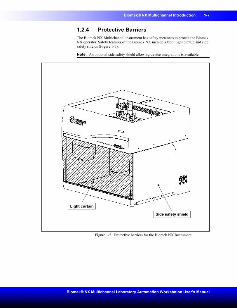
1.2.4 Protective BarriersThe Biomek NX Multichannel instrument has safety measures to protect the Biomek NX operator. Safety features of the Biomek NX include a front light curtain and side safety shields (Figure 1-5).
Note: An optional side safety shield allowing device integrations is available.
Figure 1-5. Protective barriers for the Biomek NX Instrument
Light curtain
Side safety shield
1-8 Biomek® NX Multichannel Introduction
Beckman Coulter, Inc.
1.2.4.1 Light Curtain Protection SystemWARNING: Dark non-reflective material affects the sensitivity of the light curtain and adversely impact its effectiveness. Typical lab dress, such as lab coats and latex gloves, do not degrade light curtain operation; however, it is advisable to test the impact of the all lab dress on light curtain sensitivity before operating the Biomek NX. Verify lab dress impact on light curtain sensitivity as follows: Use Manual Control in Biomek Software and insert the material no more than 1” past and approximately 21” above the light curtain panel. Make sure the solid amber indicator light changes to blinking amber.The diffuse-reflective perimeter light curtain along the front edge of the Biomek NX instrument is a standard component.
Note: Side safety shields are installed by a Beckman Coulter Service Engineer when the Biomek NX instrument is installed.
The light curtain projects a diffused array of infrared light, rather than a vertical laser-like beam (Figure 1-5). When a part of the human body or an object larger than approximately 1" in diameter (such as labware and large cables) penetrates this protective zone, the instrument shuts down immediately, stopping all pod and head operations. Some ALP operations, such as shaking or stirring, continue.
ALPs respond to a violation according to safety and operational requirements specific to each ALP. For example, a refilling reservoir may continue to operate if user safety is not compromised. ALPs that operate with a motion that could present a danger to the operator go to a safe state when the light curtain is violated.
Note: When active ALPs or optional devices are operating and the light curtain is violated, an error message may not appear until after the ALP or optional device operation is complete.
Note: It is important to become familiar with this protected zone. This reduces the possibility of causing the instrument to shut down accidentally during operation by unintentionally violating the light curtain zone.
When the instrument is sitting idle or in the paused mode, no violations are registered when the protective zone is penetrated. This allows full access to instrument components, ALPs, and labware on the Biomek NX deck during a pause or system idle time.
1.2.4.2 Side Safety ShieldsWARNING: To reduce the risk of personal injury, operate the Biomek NX instrument only with all protective shields in place.Side safety shields are installed by the Beckman Coulter Service Engineer on the Biomek NX instrument. If the instrument overhangs the table work surface on either side, a protective bottom shield is also installed on the side of the instrument overhanging the instrument envelope.
Biomek® NX Multichannel Introduction 1-9
Biomek® NX Multichannel Laboratory Automation Workstation User’s Manual
1.3 Preventive MaintenanceTo ensure optimum operation of the Biomek NX, perform the following maintenance procedures as necessary.
WARNING: To prevent injury, use proper decontamination procedures.• Wipe up all spills on the deck immediately.
• Approximately every six to twelve months, schedule a Beckman Coulter service call to lubricate the linear rail.
1.3.1 Light Curtain MaintenanceTo ensure optimum operation of the light curtain protective system, perform the following maintenance procedures as necessary:
• Once a week, verify proper operation of light curtain using Manual Control in the software (refer to Chapter 5, Manually Controlling the Biomek® NX in Biomek Software) and the light curtain test rod supplied with Biomek NX. Insert the test rod no more than 1” past and approximately 21” above the front light curtain panel. Check to make sure the solid amber indicator light changes to blinking amber each time the light curtain is violated. If not, contact a Beckman Coulter Service Engineer.
• When necessary, clean light curtain panels with a lint-free cloth.
• Once every 2-3 months, clean light curtain panels with a non-abrasive cleaner, making sure not to scratch the strip.
1-10 Biomek® NX Multichannel Introduction
Beckman Coulter, Inc.
1.4 TroubleshootingCAUTION: If service is required, contact a Beckman Coulter Service Engineer.Perform the troubleshooting techniques provided in Table 1-2 when necessary.
In the case of any other instrument-related problems, contact a Beckman Coulter Service Engineer.
Note: For troubleshooting information regarding the specific pods, refer to the Troubleshooting section in those respective chapters.
Table 1-2. Troubleshooting the Biomek NX InstrumentIf Then
All indicator lights are out Check fusesThe power is on, but system does not run
Check fuses
The fuses appear burned or filaments are broken
Change fuses (refer to Section 1.4.1, Changing Fuses)
All indicator lights are out, the power is on, the fuses are okay, and the system does not run
Contact a Beckman Coulter Service Engineer
Power is lost to pod Contact a Beckman Coulter Service Engineer.
Y-axis motion is choppy Contact a Beckman Coulter Service Engineer.
A grinding or growling noise is heard Contact a Beckman Coulter Service Engineer.
Experiencing problems relating to the Multichannel Pod
Refer to Section 2.5, Troubleshooting in Chapter 2, Multichannel Pod, for more information.
Constant light curtain errors, even when no violation
Clean light curtain panels as described in Section 1.3.1, Light Curtain Maintenance.
Contact your Beckman Coulter Service Engineer.
Biomek® NX Multichannel Introduction 1-11
Biomek® NX Multichannel Laboratory Automation Workstation User’s Manual
1.4.1 Changing FusesWARNING: Do not remove tower covers to access electrical wiring or fuses. Change only the fuses that are accessed from the outside of the instrument, without removing covers. Contact a Beckman Coulter Service Engineer if further access is required.WARNING: Turn off and unplug power to the instrument before changing fuses. Failure to do so can cause electrical shock or equipment damage.The Biomek NX instrument uses any AC power source between 100V and 240V. The fuse holder holds two European fuses and one North American fuse.
Fuses are located in the outside right tower (Figure 1-6). If power is lost, check the fuses that are accessed from the outside of the instrument.
If fuses appear burned, change them by completing the following:
1. Turn off the instrument power switch.
2. Unplug the instrument from the power source.
1-12 Biomek® NX Multichannel Introduction
Beckman Coulter, Inc.
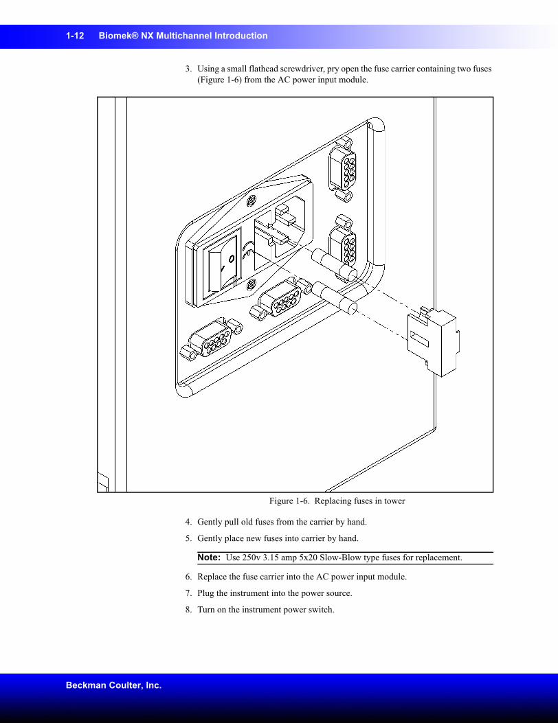
3. Using a small flathead screwdriver, pry open the fuse carrier containing two fuses (Figure 1-6) from the AC power input module.
Figure 1-6. Replacing fuses in tower
4. Gently pull old fuses from the carrier by hand.
5. Gently place new fuses into carrier by hand.
Note: Use 250v 3.15 amp 5x20 Slow-Blow type fuses for replacement.
6. Replace the fuse carrier into the AC power input module.
7. Plug the instrument into the power source.
8. Turn on the instrument power switch.
2-1
Biomek® NX Multichannel Laboratory Automation Workstation User’s Manual
2 Multichannel Pod
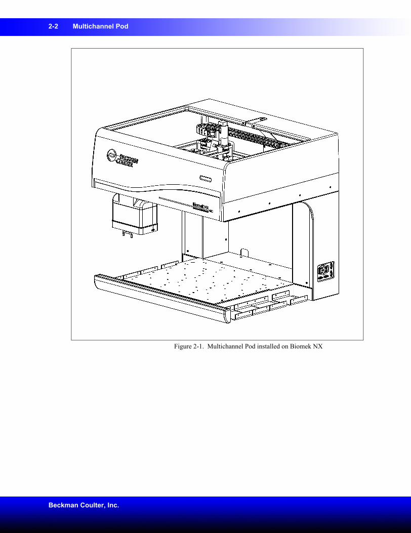
2.1 OverviewThe Multichannel Pod is a self-contained working unit on the Biomek NX Multichannel Laboratory Automation Workstation (Figure 2-1). The Multichannel Pod is a full-microplate replication tool incorporating a gripper and interchangeable heads to accommodate a variety of functions (refer to Section 2.2, Interchangeable Heads).
The Multichannel Pod contains its own electrical cabling, communication, and pneumatic connections with the base unit, and it interacts with ALPs located over the entire deck area of the Biomek NX.
2-2 Multichannel Pod
Beckman Coulter, Inc.
Figure 2-1. Multichannel Pod installed on Biomek NX
Multichannel Pod 2-3
Biomek® NX Multichannel Laboratory Automation Workstation User’s Manual
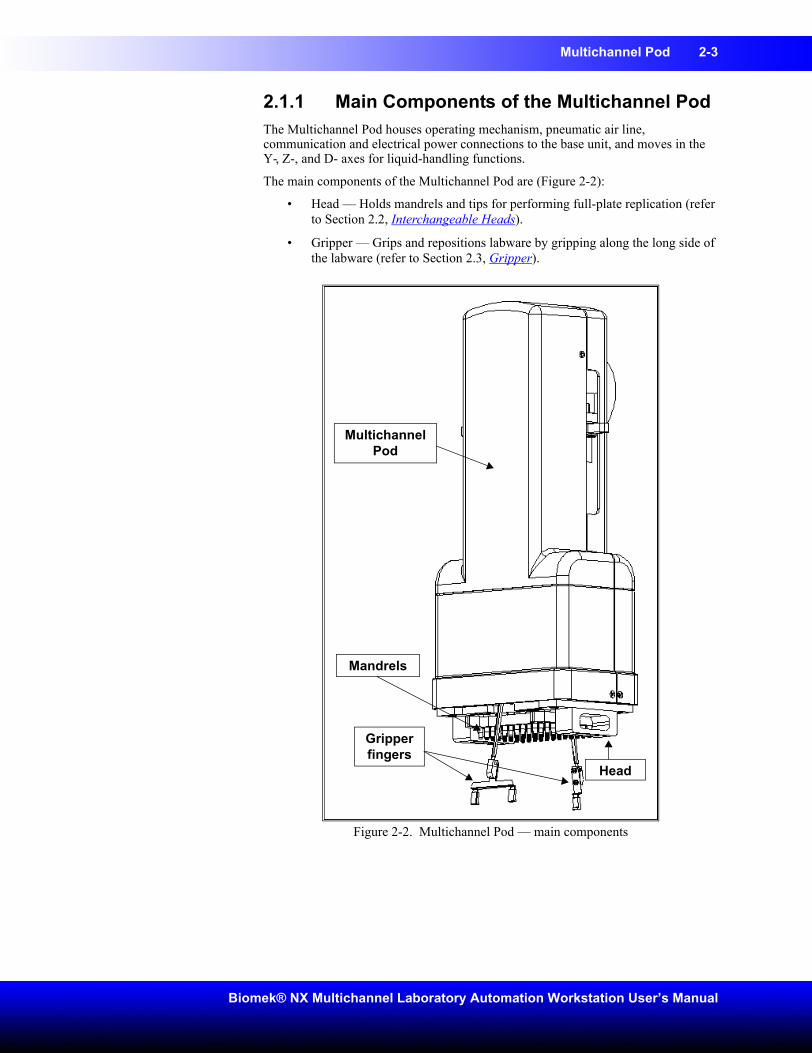
2.1.1 Main Components of the Multichannel PodThe Multichannel Pod houses operating mechanism, pneumatic air line, communication and electrical power connections to the base unit, and moves in the Y-, Z-, and D- axes for liquid-handling functions.
The main components of the Multichannel Pod are (Figure 2-2):
• Head — Holds mandrels and tips for performing full-plate replication (refer to Section 2.2, Interchangeable Heads).
• Gripper — Grips and repositions labware by gripping along the long side of the labware (refer to Section 2.3, Gripper).
Figure 2-2. Multichannel Pod — main components
Gripper fingers
Mandrels
Head
Multichannel Pod
2-4 Multichannel Pod
Beckman Coulter, Inc.
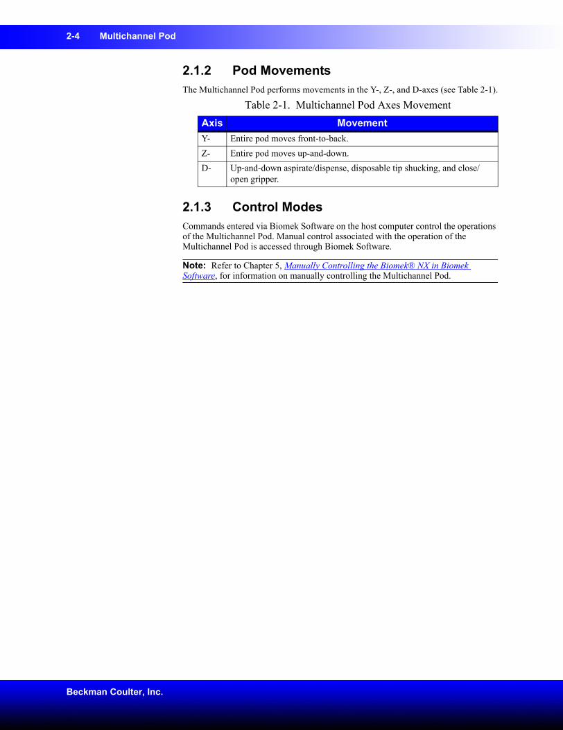
2.1.2 Pod MovementsThe Multichannel Pod performs movements in the Y-, Z-, and D-axes (see Table 2-1).
2.1.3 Control ModesCommands entered via Biomek Software on the host computer control the operations of the Multichannel Pod. Manual control associated with the operation of the Multichannel Pod is accessed through Biomek Software.
Note: Refer to Chapter 5, Manually Controlling the Biomek® NX in Biomek Software, for information on manually controlling the Multichannel Pod.
Table 2-1. Multichannel Pod Axes MovementAxis MovementY- Entire pod moves front-to-back.Z- Entire pod moves up-and-down.D- Up-and-down aspirate/dispense, disposable tip shucking, and close/
open gripper.
Multichannel Pod 2-5
Biomek® NX Multichannel Laboratory Automation Workstation User’s Manual
2.2 Interchangeable HeadsAn interchangeable, multichannel head is attached to the bottom of the pod to perform a specific liquid-handling procedure. Depending on the head and the desired liquid-handling procedure, different tip types may be used.
Presently, there are three types of heads that can be attached to the Multichannel Pod:
• 96-Channel 20 µL Head
• 96-Channel 200 µL Head
• 384-Channel 30 µL Head
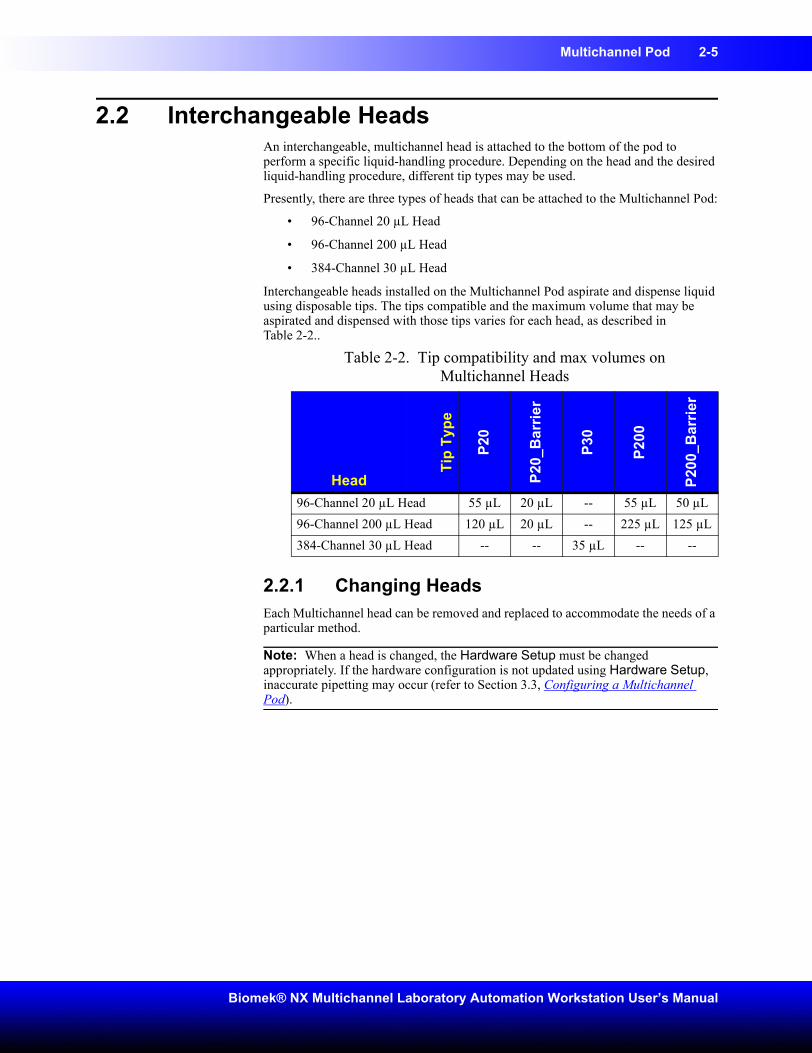
Interchangeable heads installed on the Multichannel Pod aspirate and dispense liquid using disposable tips. The tips compatible and the maximum volume that may be aspirated and dispensed with those tips varies for each head, as described inTable 2-2..
2.2.1 Changing HeadsEach Multichannel head can be removed and replaced to accommodate the needs of a particular method.
Note: When a head is changed, the Hardware Setup must be changed appropriately. If the hardware configuration is not updated using Hardware Setup, inaccurate pipetting may occur (refer to Section 3.3, Configuring a Multichannel Pod).
Table 2-2. Tip compatibility and max volumes on Multichannel Heads
Head
Tip
Type
P20
P20_
Bar
rier
P30
P200
P200
_Bar
rier
96-Channel 20 µL Head 55 µL 20 µL -- 55 µL 50 µL96-Channel 200 µL Head 120 µL 20 µL -- 225 µL 125 µL384-Channel 30 µL Head -- -- 35 µL -- --
2-6 Multichannel Pod
Beckman Coulter, Inc.
2.2.1.1 Removing HeadsCAUTION: To prevent damage due to electrical static discharge (ESD), wear a wrist ground strap when handling a multichannel head.
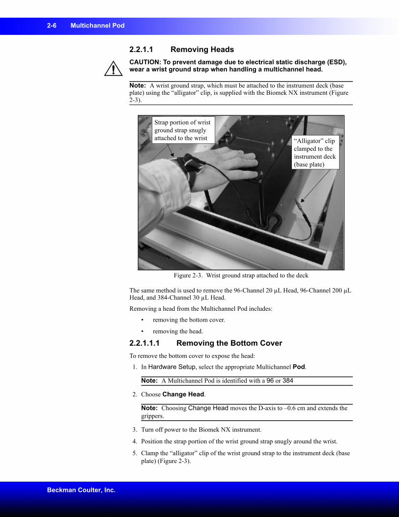
Note: A wrist ground strap, which must be attached to the instrument deck (base plate) using the “alligator” clip, is supplied with the Biomek NX instrument (Figure 2-3).
Figure 2-3. Wrist ground strap attached to the deck
The same method is used to remove the 96-Channel 20 µL Head, 96-Channel 200 µL Head, and 384-Channel 30 µL Head.
Removing a head from the Multichannel Pod includes:
• removing the bottom cover.
• removing the head.
2.2.1.1.1 Removing the Bottom CoverTo remove the bottom cover to expose the head:
1. In Hardware Setup, select the appropriate Multichannel Pod.
Note: A Multichannel Pod is identified with a 96 or 384
2. Choose Change Head.
Note: Choosing Change Head moves the D-axis to –0.6 cm and extends the grippers.
3. Turn off power to the Biomek NX instrument.
4. Position the strap portion of the wrist ground strap snugly around the wrist.
5. Clamp the “alligator” clip of the wrist ground strap to the instrument deck (base plate) (Figure 2-3).
“Alligator” clip clamped to the instrument deck (base plate)
Strap portion of wrist ground strap snugly attached to the wrist
Multichannel Pod 2-7
Biomek® NX Multichannel Laboratory Automation Workstation User’s Manual
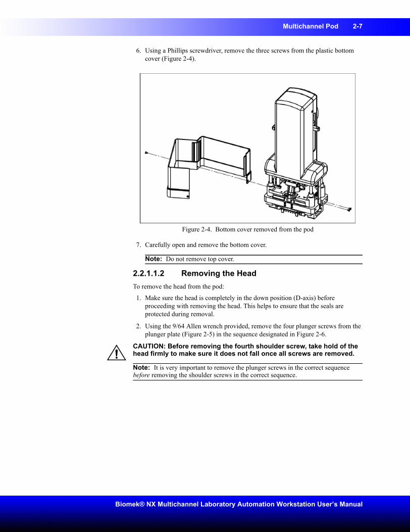
6. Using a Phillips screwdriver, remove the three screws from the plastic bottom cover (Figure 2-4).
Figure 2-4. Bottom cover removed from the pod
7. Carefully open and remove the bottom cover.
Note: Do not remove top cover.
2.2.1.1.2 Removing the HeadTo remove the head from the pod:
1. Make sure the head is completely in the down position (D-axis) before proceeding with removing the head. This helps to ensure that the seals are protected during removal.
2. Using the 9/64 Allen wrench provided, remove the four plunger screws from the plunger plate (Figure 2-5) in the sequence designated in Figure 2-6.
CAUTION: Before removing the fourth shoulder screw, take hold of the head firmly to make sure it does not fall once all screws are removed.
Note: It is very important to remove the plunger screws in the correct sequence before removing the shoulder screws in the correct sequence.
2-8 Multichannel Pod
Beckman Coulter, Inc.
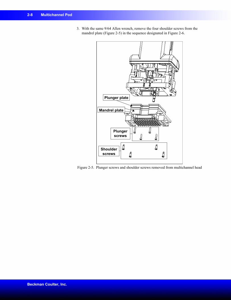
3. With the same 9/64 Allen wrench, remove the four shoulder screws from the mandrel plate (Figure 2-5) in the sequence designated in Figure 2-6.
Figure 2-5. Plunger screws and shoulder screws removed from multichannel head
Shoulder screws
Plunger screws
Plunger plate
Mandrel plate
Multichannel Pod 2-9
Biomek® NX Multichannel Laboratory Automation Workstation User’s Manual
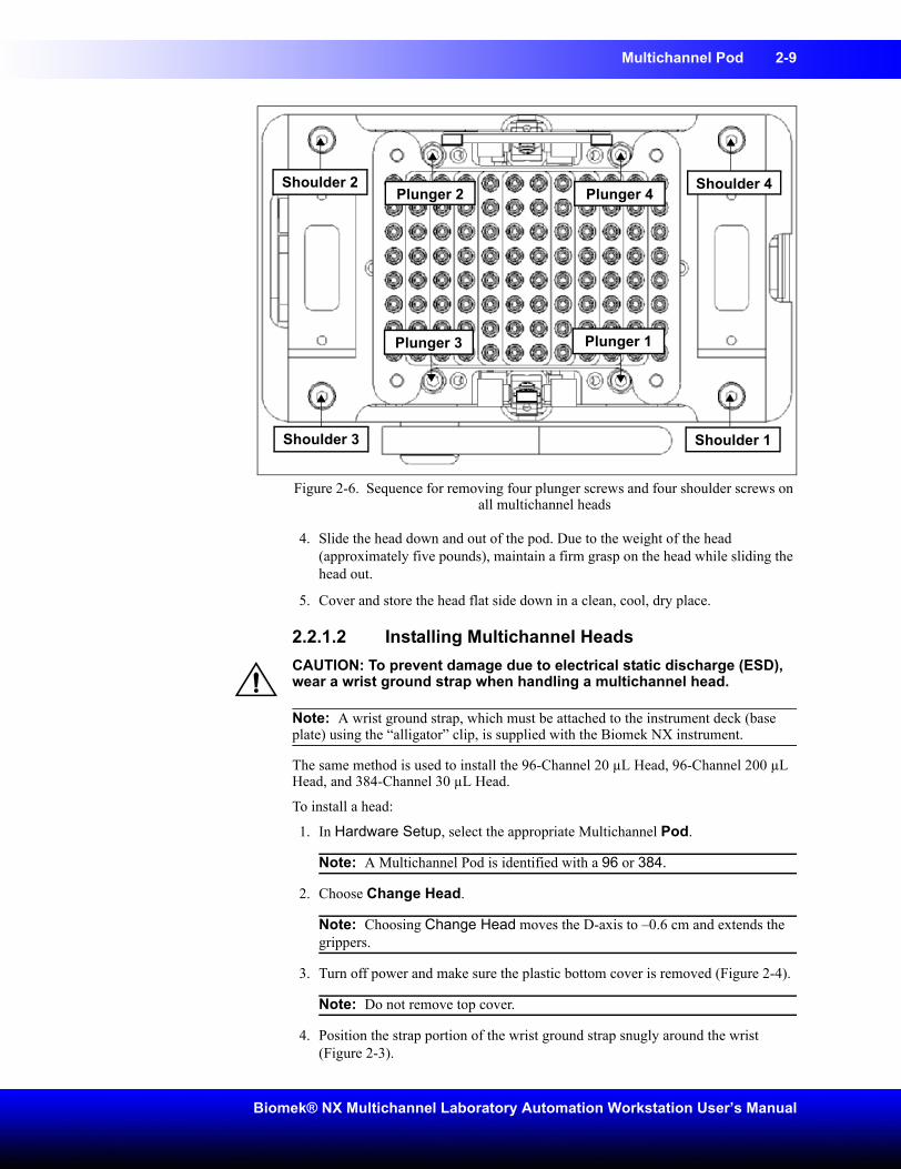
Figure 2-6. Sequence for removing four plunger screws and four shoulder screws on all multichannel heads
4. Slide the head down and out of the pod. Due to the weight of the head (approximately five pounds), maintain a firm grasp on the head while sliding the head out.
5. Cover and store the head flat side down in a clean, cool, dry place.
2.2.1.2 Installing Multichannel HeadsCAUTION: To prevent damage due to electrical static discharge (ESD), wear a wrist ground strap when handling a multichannel head.
Note: A wrist ground strap, which must be attached to the instrument deck (base plate) using the “alligator” clip, is supplied with the Biomek NX instrument.
The same method is used to install the 96-Channel 20 µL Head, 96-Channel 200 µL Head, and 384-Channel 30 µL Head.
To install a head:
1. In Hardware Setup, select the appropriate Multichannel Pod.
Note: A Multichannel Pod is identified with a 96 or 384.
2. Choose Change Head.
Note: Choosing Change Head moves the D-axis to –0.6 cm and extends the grippers.
3. Turn off power and make sure the plastic bottom cover is removed (Figure 2-4).
Note: Do not remove top cover.
4. Position the strap portion of the wrist ground strap snugly around the wrist (Figure 2-3).
Plunger 1
Plunger 2
Plunger 3
Plunger 4
Shoulder 1
Shoulder 4Shoulder 2
Shoulder 3
2-10 Multichannel Pod
Beckman Coulter, Inc.
5. Clamp the “alligator” clip of the wrist ground strap to the instrument deck (base plate) (Figure 2-3).
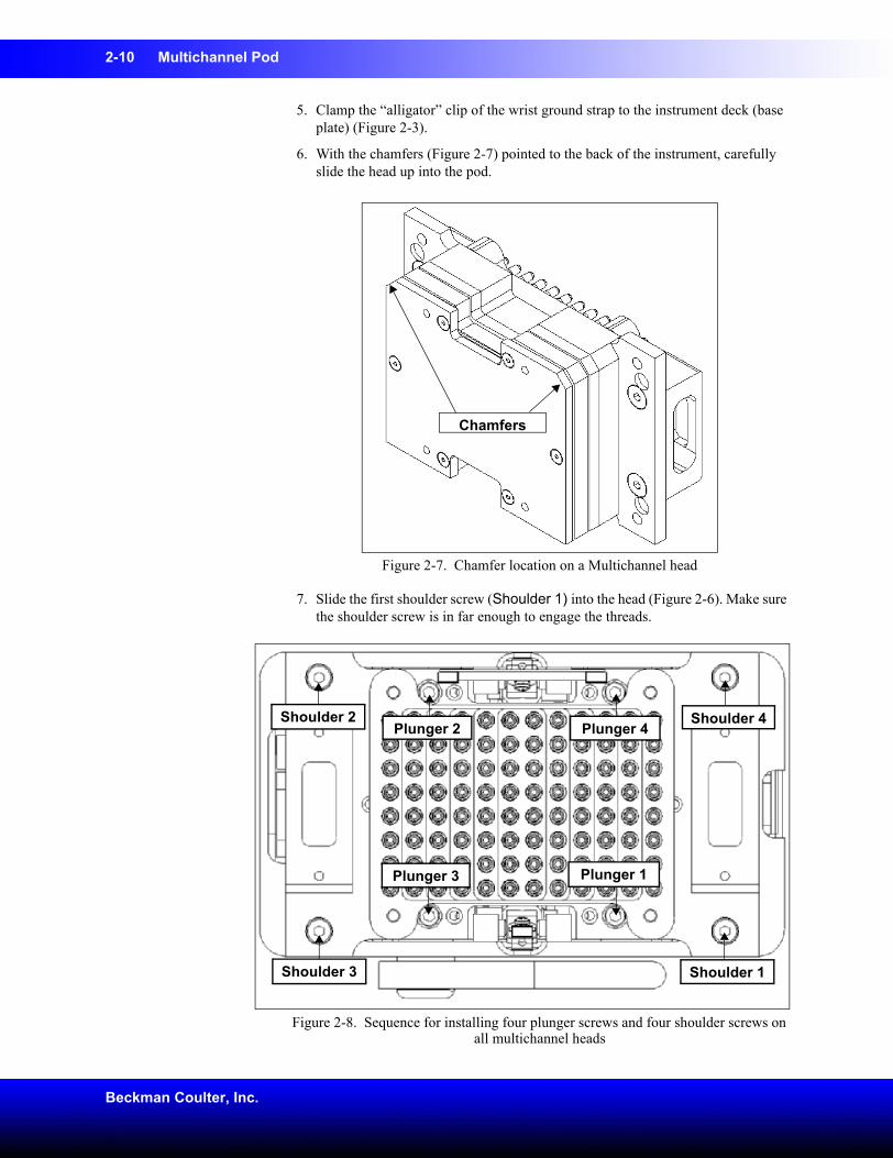
6. With the chamfers (Figure 2-7) pointed to the back of the instrument, carefully slide the head up into the pod.
Figure 2-7. Chamfer location on a Multichannel head
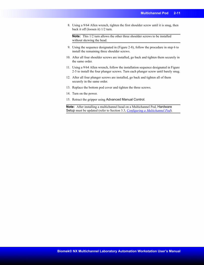
7. Slide the first shoulder screw (Shoulder 1) into the head (Figure 2-6). Make sure the shoulder screw is in far enough to engage the threads.
Figure 2-8. Sequence for installing four plunger screws and four shoulder screws on all multichannel heads
Chamfers
Plunger 1
Plunger 2
Plunger 3
Plunger 4
Shoulder 1
Shoulder 4Shoulder 2
Shoulder 3
Multichannel Pod 2-11
Biomek® NX Multichannel Laboratory Automation Workstation User’s Manual
8. Using a 9/64 Allen wrench, tighten the first shoulder screw until it is snug, then back it off (loosen it) 1/2 turn.
Note: This 1/2 turn allows the other three shoulder screws to be installed without skewing the head.
9. Using the sequence designated in (Figure 2-8), follow the procedure in step 6 to install the remaining three shoulder screws.
10. After all four shoulder screws are installed, go back and tighten them securely in the same order.
11. Using a 9/64 Allen wrench, follow the installation sequence designated in Figure 2-5 to install the four plunger screws. Turn each plunger screw until barely snug.
12. After all four plunger screws are installed, go back and tighten all of them securely in the same order.
13. Replace the bottom pod cover and tighten the three screws.
14. Turn on the power.
15. Retract the gripper using Advanced Manual Control.
Note: After installing a multichannel head on a Multichannel Pod, Hardware Setup must be updated (refer to Section 3.3, Configuring a Multichannel Pod).
2-12 Multichannel Pod
Beckman Coulter, Inc.
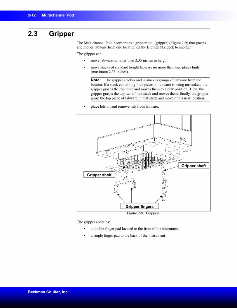
2.3 Gripper The Multichannel Pod incorporates a gripper tool (gripper) (Figure 2-9) that grasps and moves labware from one location on the Biomek NX deck to another.
The gripper can:
• move labware no taller than 2.35 inches in height.
• move stacks of standard height labware no more than four plates high (maximum 2.35 inches).
Note: The gripper stackes and unstackes groups of labware from the bottom. If a stack containing four pieces of labware is being unstacked, the gripper grasps the top three and moves them to a new position. Then, the gripper grasps the top two of that stack and moves them; finally, the gripper grasp the top piece of labware in that stack and move it to a new location.
• place lids on and remove lids from labware.
Figure 2-9. Grippers
The gripper contains:
• a double finger pad located to the front of the instrument
• a single finger pad to the back of the instrument
Gripper shaft
Gripper shaft
Gripper fingers
Multichannel Pod 2-13
Biomek® NX Multichannel Laboratory Automation Workstation User’s Manual
2.3.1 Framing the GripperWARNING: The gripper may bend if not taught (framed) properly with the AccuFrame. The gripper is framed during installation by a Beckman Coulter Service Engineer. The framing process for the gripper must be repeated when:
• A head is changed.
• Extraordinary circumstances occur, such as accidentally bending a gripper.
Should the gripper need to be framed, refer to Section 4.4, Framing the Gripper.
2-14 Multichannel Pod
Beckman Coulter, Inc.
2.4 Preventive MaintenanceThe Multichannel Pod requires little preventive maintenance; however, to ensure optimum operation, perform the following maintenance procedures as necessary.
WARNING: To prevent injury, use proper decontamination procedures.
• Wipe up all spills immediately.
• Return heads to their original packaging when they are not in use.
• Check connections periodically to make sure that all are secure (refer to Section 2.5, Troubleshooting).
• Check and tighten head mount screws and gripper mount screws.
• Make sure that gripper shafts are straight and gripper pads are in good condition. Replace as needed (refer to Section 2.5.1, Replacing Gripper Fingers).
Multichannel Pod 2-15
Biomek® NX Multichannel Laboratory Automation Workstation User’s Manual
2.5 TroubleshootingWARNING: Do not connect or disconnect any cable while power is applied to the Biomek NX.Perform the troubleshooting techniques provided in Table 2-3 when necessary.
Note: In the case of any other pod-related problems, contact a Beckman Coulter Service Engineer.
Table 2-3. Multichannel Pod TroubleshootingIf Then
Power is lost to the pod. Contact a Beckman Coulter Service Engineer.
The gripper is not deploying. Check input air pressure.
Contact a Beckman Coulter Service Engineer.
Power is lost to the Y-axis. Contact a Beckman Coulter Service Engineer.
The head does not work properly. Contact a Beckman Coulter Service Engineer.
Aspiration or dispense actions are not accurate.
Calibrate pipetting techniques using slope and offset.
Contact a Beckman Coulter Service Engineer.
A mandrel on the head is damaged. Contact a Beckman Coulter Service Engineer—the head may need to be returned to the factory for repair or replacement.
Front gripper shaft is bent. Replace the front gripper fingers using Front Removeable Rod Assembly, Beckman Coulter Part Number 394062. Refer to Section 2.5.1, Replacing Gripper Fingers, for instructions.
Front gripper pads look worn.
Rear gripper shaft is bent. Replace the rear gripper fingers using Rear Removeable Rod Assembly, Beckman Coulter Part Number 394063. Refer to Section 2.5.1, Replacing Gripper Fingers, for instructions.
Rear gripper pads look worn.
2-16 Multichannel Pod
Beckman Coulter, Inc.
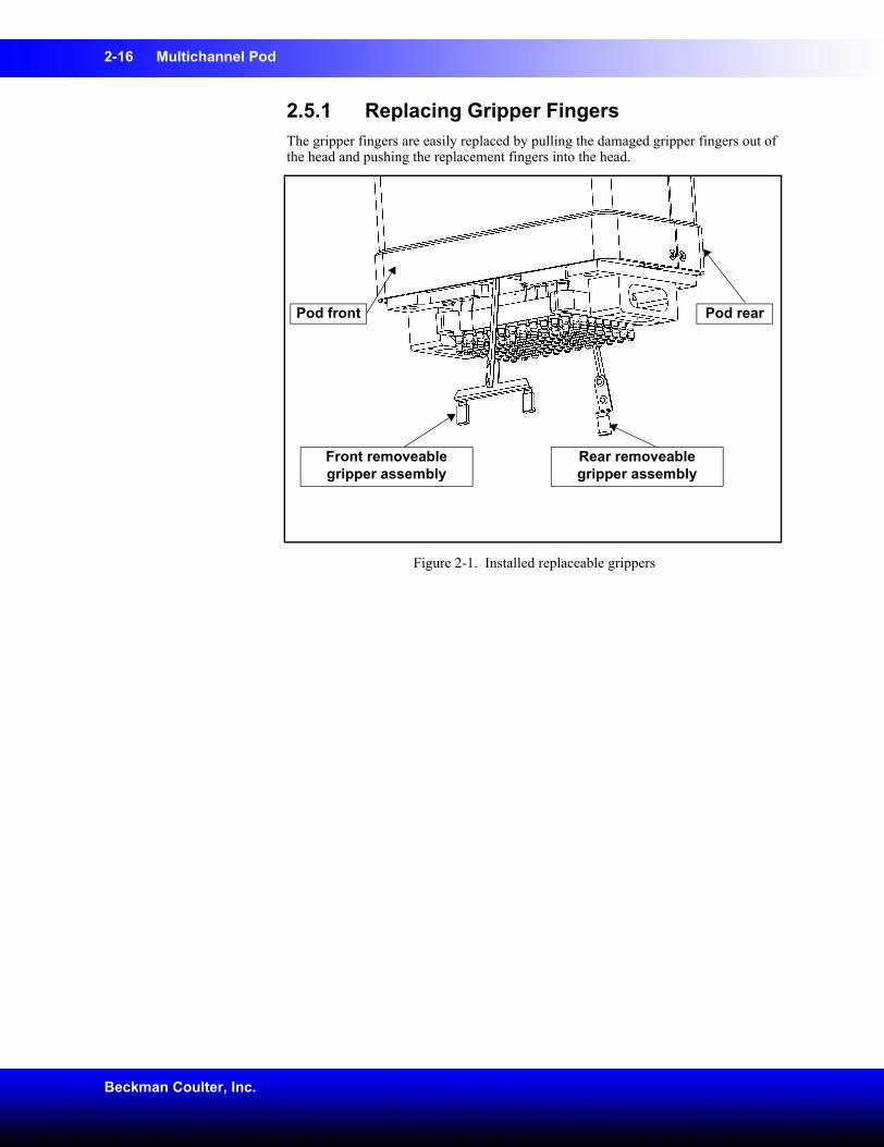
2.5.1 Replacing Gripper FingersThe gripper fingers are easily replaced by pulling the damaged gripper fingers out of the head and pushing the replacement fingers into the head.
Figure 2-1. Installed replaceable grippers
Rear removeable gripper assembly
Front removeable gripper assembly
Pod front Pod rear
Multichannel Pod 2-17
Biomek® NX Multichannel Laboratory Automation Workstation User’s Manual
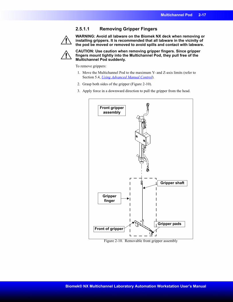
2.5.1.1 Removing Gripper FingersWARNING: Avoid all labware on the Biomek NX deck when removing or installing grippers. It is recommended that all labware in the vicinity of the pod be moved or removed to avoid spills and contact with labware.CAUTION: Use caution when removing gripper fingers. Since gripper fingers mount tightly into the Multichannel Pod, they pull free of the Multichannel Pod suddenly.To remove grippers:
1. Move the Multichannel Pod to the maximum Y- and Z-axis limits (refer to Section 5.4, Using Advanced Manual Control).
2. Grasp both sides of the gripper (Figure 2-10).
3. Apply force in a downward direction to pull the gripper from the head.
Figure 2-10. Removable front gripper assembly
Front of gripper
Gripper shaft
Gripper pads
Front gripper assembly
Gripper finger
2-18 Multichannel Pod
Beckman Coulter, Inc.
2.5.1.2 Installing Gripper FingersWARNING: Avoid all labware on the Biomek NX deck when removing or installing grippers. It is recommended that all labware in the vicinity of the pod be moved or removed to avoid spills and contact with labware.To install gripper fingers:
1. Move the Multichannel Pod to the maximum Y- and Z-axis limits (refer to Section 5.4, Using Advanced Manual Control).
2. Orient the gripper so that the front of the gripper faces the outside and gripper pads face the inside of the Multichannel Pod (Figure 2-10).
3. Grasping both sides of the gripper, push the gripper straight up into the Multichannel Pod.
Note: A click can be heard and felt when the gripper fingers are seated in the Multichannel Pod.
4. Pull down on the gripper to ensure that it is fully seated in the pod.
5. Reframe the Multichannel Pod (refer to Section 4.4, Framing the Gripper).

3-1
Biomek® NX Multichannel Laboratory Automation Workstation User’s Manual
3 Configuring the Biomek® NX Multichannel in Biomek Software
3.1 OverviewThe Biomek NX Multichannel Laboratory Automation Workstation must be configured in Biomek Software to ensure proper operation. Hardware Setup tells Biomek Software what devices, pods, and heads to expect on the instrument by providing a connection between the instrument and the software. This connection is established by installing, configuring, and removing devices in Hardware Setup.
Any active ALPs that require a CAN communication or other devices integrated on the deck of the Biomek NX Multichannel must also be configured in Hardware Setup. Refer to the ALPs User’s Manual or the specific device integration manual for instructions on configuring the ALP or device in Hardware Setup.
CAUTION: Do not make any changes to the pod axes limits in Hardware Setup without contacting a Beckman Coulter Service Engineer or Beckman Coulter Customer Technical Support.Hardware Setup is used for:
• Configuring the Biomek NX Multichannel Instrument (Section 3.2).
• Configuring a Multichannel Pod (Section 3.3).
• Saving, Restoring, and Deleting Settings (Section 3.4).
3-2 Configuring the Biomek® NX Multichannel in Biomek Software
Beckman Coulter, Inc.
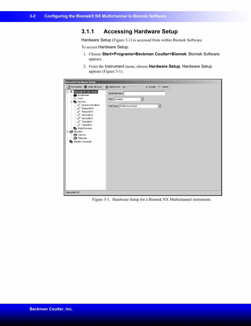
3.1.1 Accessing Hardware SetupHardware Setup (Figure 3-1) is accessed from within Biomek Software.
To access Hardware Setup:
1. Choose Start>Programs>Beckman Coulter>Biomek. Biomek Software appears.
2. From the Instrument menu, choose Hardware Setup. Hardware Setup appears (Figure 3-1).
Figure 3-1. Hardware Setup for a Biomek NX Multichannel instrument.
Configuring the Biomek® NX Multichannel in Biomek Software 3-3
Biomek® NX Multichannel Laboratory Automation Workstation User’s Manual
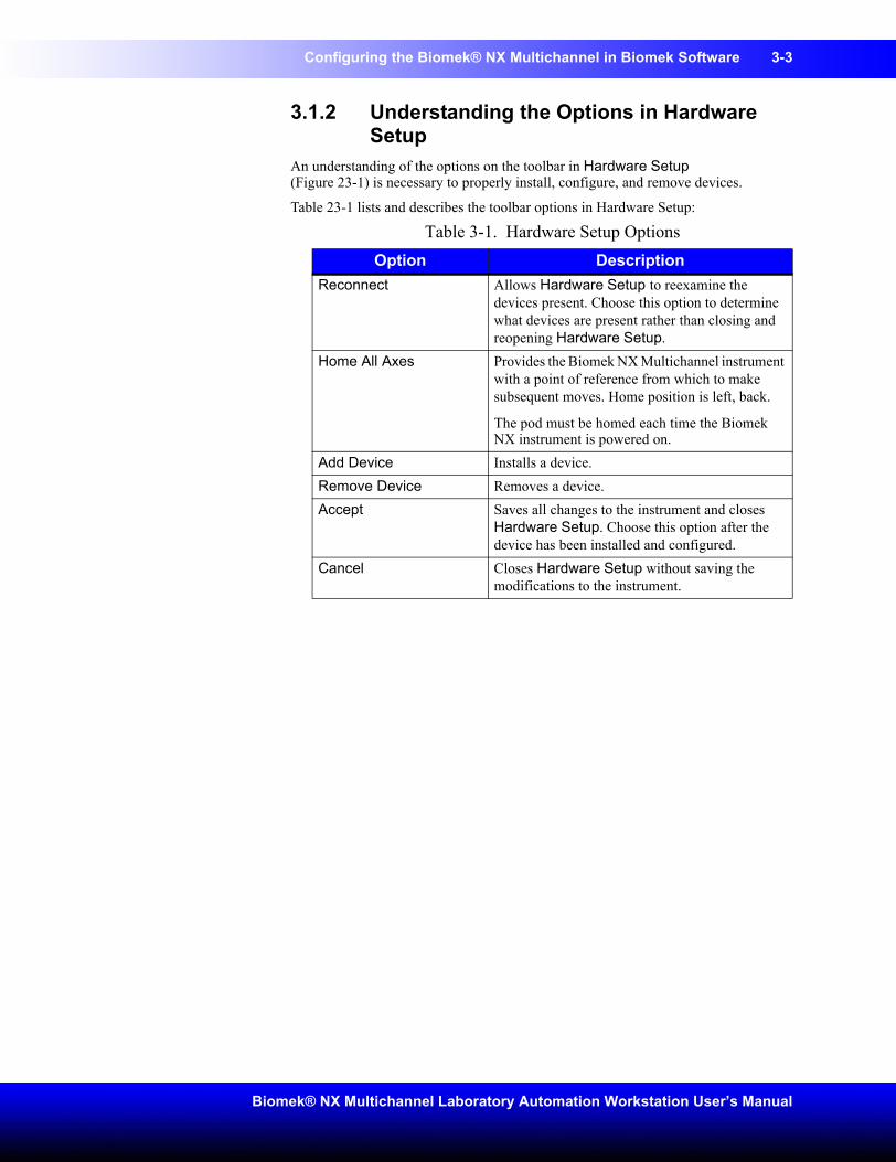
3.1.2 Understanding the Options in Hardware Setup
An understanding of the options on the toolbar in Hardware Setup (Figure 23-1) is necessary to properly install, configure, and remove devices.
Table 23-1 lists and describes the toolbar options in Hardware Setup:
Table 3-1. Hardware Setup OptionsOption Description
Reconnect Allows Hardware Setup to reexamine the devices present. Choose this option to determine what devices are present rather than closing and reopening Hardware Setup.
Home All Axes Provides the Biomek NX Multichannel instrument with a point of reference from which to make subsequent moves. Home position is left, back.
The pod must be homed each time the Biomek NX instrument is powered on.
Add Device Installs a device.Remove Device Removes a device.Accept Saves all changes to the instrument and closes
Hardware Setup. Choose this option after the device has been installed and configured.
Cancel Closes Hardware Setup without saving the modifications to the instrument.
3-4 Configuring the Biomek® NX Multichannel in Biomek Software
Beckman Coulter, Inc.
3.2 Configuring the Biomek NX Multichannel Instrument
The Biomek NX Multichannel instrument is configured in Hardware Setup to relate information about the configuration of the multichannel pod on the system to the software and to specify the communications port to which it is connected.
To configure the Biomek NX instrument:
1. From Hardware Setup, select Biomek® NX from the left pane. The configuration view appears in the right pane (Figure 3-1).
2. Make sure the serial number listed in Hardware Setup corresponds to the serial number on the Biomek NX instrument.
3. Choose the appropriate Port.
4. Choose Accept. Hardware Setup closes.
Note: Accept must be chosen after the instrument has been configured to allow Hardware Setup to accept the configurations. However, other devices may be configured simultaneously as the Biomek NX instrument is configured, and Accept may be chosen after all devices have been configured.
Note: An asterisk next to the device indicates the device has been modified since the instrument was loaded.
Configuring the Biomek® NX Multichannel in Biomek Software 3-5
Biomek® NX Multichannel Laboratory Automation Workstation User’s Manual
3.3 Configuring a Multichannel PodThe Multichannel Pod is a full-microplate replication tool incorporating a gripper and interchangeable heads to accommodate a variety of functions (refer to Chapter 2, Multichannel Pod).
Configuring a Multichannel Pod in Hardware Setup includes:
• Configuring a New Head (Section 3.3.1).
• Setting Multichannel Pod Properties (Section 3.3.2), as instructed by a Beckman Coulter Service Engineer.
Note: The settings for a Multichannel Pod can be saved, restored, and deleted (refer to Section 3.4, Saving, Restoring, and Deleting Settings).
3.3.1 Configuring a New HeadWhen a head on a Multichannel Pod is changed, the Hardware Setup must be changed appropriately.
CAUTION: If the hardware configuration is not updated using Hardware Setup, hardware crashes or inaccurate liquid transfer may occur.
CAUTION: To avoid hardware crashes, a new D-axis limit must be established and the gripper framed in the Biomek Software after the head has been configured in Hardware Setup.To change the head on a Multichannel Pod (refer to Section 2.2.1, Changing Heads) and then configure Hardware Setup according to the following instructions.
1. In Hardware Setup, select the Pod.
2. Change the Serial Number to correspond to the serial number on the new head.
3-6 Configuring the Biomek® NX Multichannel in Biomek Software
Beckman Coulter, Inc.
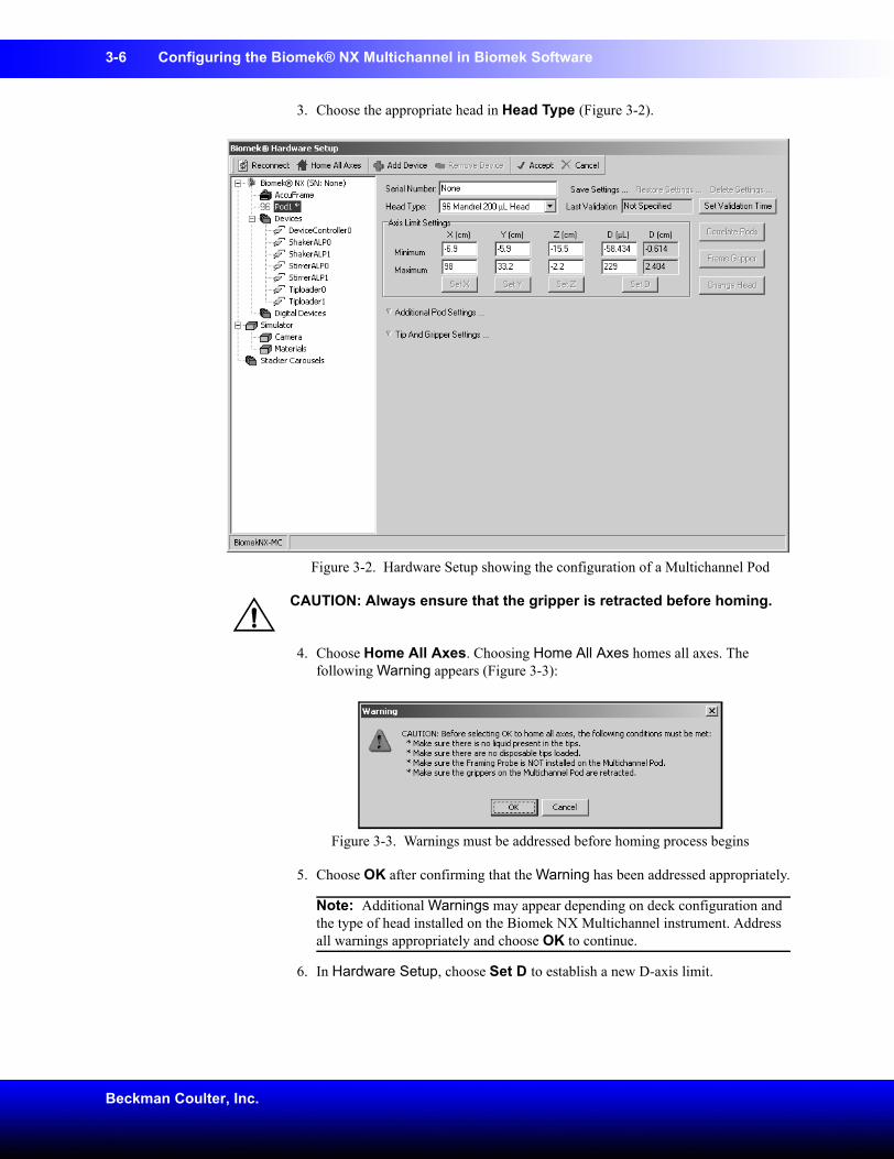
3. Choose the appropriate head in Head Type (Figure 3-2).
Figure 3-2. Hardware Setup showing the configuration of a Multichannel Pod
CAUTION: Always ensure that the gripper is retracted before homing.
4. Choose Home All Axes. Choosing Home All Axes homes all axes. The following Warning appears (Figure 3-3):
Figure 3-3. Warnings must be addressed before homing process begins
5. Choose OK after confirming that the Warning has been addressed appropriately.
Note: Additional Warnings may appear depending on deck configuration and the type of head installed on the Biomek NX Multichannel instrument. Address all warnings appropriately and choose OK to continue.
6. In Hardware Setup, choose Set D to establish a new D-axis limit.
Configuring the Biomek® NX Multichannel in Biomek Software 3-7
Biomek® NX Multichannel Laboratory Automation Workstation User’s Manual
7. Choose Set Z to establish a new Z-axis limit.
8. Frame the gripper according to the procedures outlined in Section 4.4, Framing the Gripper.
Note: An asterisk next to the pod indicates that the head has been modified since the workspace was loaded.
Note: Change Head is used only when physically removing or installing a head. Choosing Change Head moves the D-axis to –0.6 cm and extends the gripper to remove and install a head.
3.3.2 Setting Multichannel Pod PropertiesMost of the properties, including pod settings and axes limits, of a Multichannel Pod are initially configured by a Beckman Coulter Service Engineer in Hardware Setup and should not be modified without specific instructions from a Beckman Coulter Service Engineer or Beckman Coulter Technical Support.
CAUTION: Do not make any changes to the pod axes limits without contacting a Beckman Coulter Service Engineer or Beckman Coulter Customer Technical Support.Table 3-2 describes the pod properties and axes limits listed in Hardware Setup for a Multichannel Pod.
Table 3-2. Multichannel Pod PropertiesProperty Description
Additional Roving Height Margin above the default height for the pod as it moves over everything on the deck.
Additional Timeout Specifies a number of seconds to wait in addition to the normal time it takes to carry out a step before a timeout error occurs. Use when experiencing timeout problems without actual hardware problems.
Always move to max Z when roving
Check this field to move the pod to its maximum height during any move in the X- or Y-axis.
Enable Plate Sensor Enables the plate sensor on the gripper to sense labware. Default setting is checked (enabled). Refer to Section 3.3.2.1, Using the Plate Sensor.
Final D Position(under Tip Load Settings)
Position the pod returns to along the D-axis after loading tips.
Final D Position(under Tip Unload Settings)
Position the pod returns to along the D-axis after unloading tips.
Gripper Extend Time Specifies the time the pod takes to extend grippers.Gripper Retract Time Specifies the time the pod takes to retract grippers.
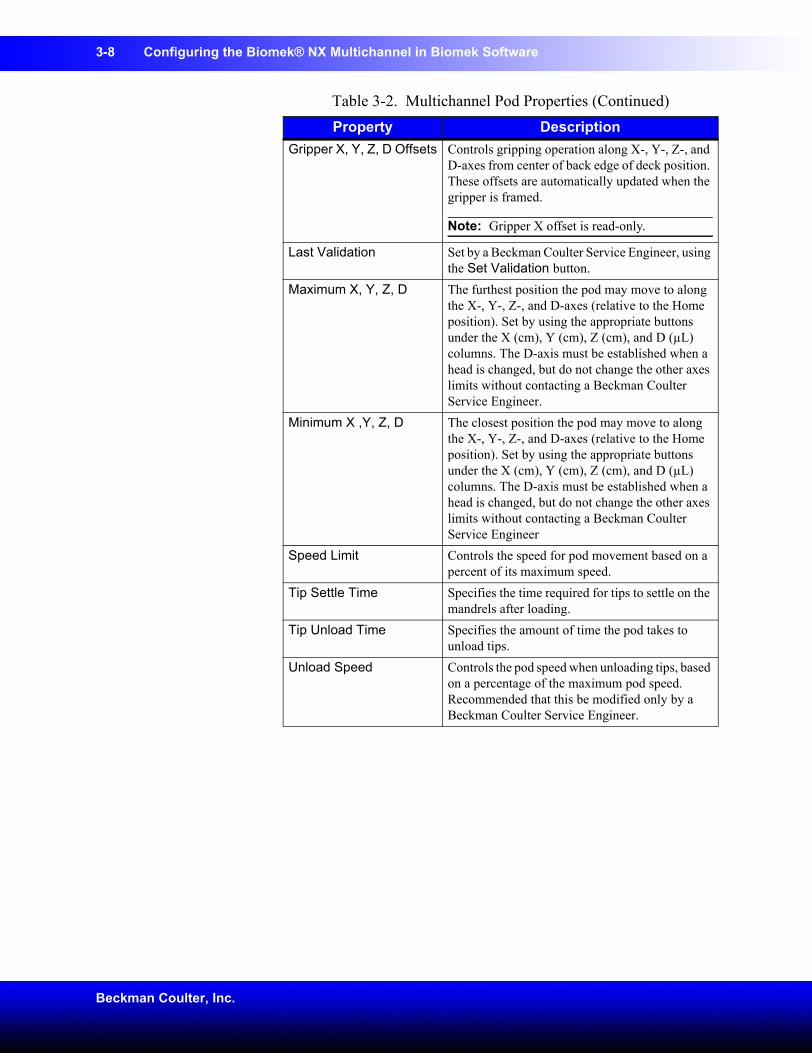
3-8 Configuring the Biomek® NX Multichannel in Biomek Software
Beckman Coulter, Inc.
Gripper X, Y, Z, D Offsets Controls gripping operation along X-, Y-, Z-, and D-axes from center of back edge of deck position. These offsets are automatically updated when the gripper is framed.
Note: Gripper X offset is read-only.
Last Validation Set by a Beckman Coulter Service Engineer, using the Set Validation button.
Maximum X, Y, Z, D The furthest position the pod may move to along the X-, Y-, Z-, and D-axes (relative to the Home position). Set by using the appropriate buttons under the X (cm), Y (cm), Z (cm), and D (µL) columns. The D-axis must be established when a head is changed, but do not change the other axes limits without contacting a Beckman Coulter Service Engineer.
Minimum X ,Y, Z, D The closest position the pod may move to along the X-, Y-, Z-, and D-axes (relative to the Home position). Set by using the appropriate buttons under the X (cm), Y (cm), Z (cm), and D (µL) columns. The D-axis must be established when a head is changed, but do not change the other axes limits without contacting a Beckman Coulter Service Engineer
Speed Limit Controls the speed for pod movement based on a percent of its maximum speed.
Tip Settle Time Specifies the time required for tips to settle on the mandrels after loading.
Tip Unload Time Specifies the amount of time the pod takes to unload tips.
Unload Speed Controls the pod speed when unloading tips, based on a percentage of the maximum pod speed. Recommended that this be modified only by a Beckman Coulter Service Engineer.
Table 3-2. Multichannel Pod Properties (Continued)Property Description
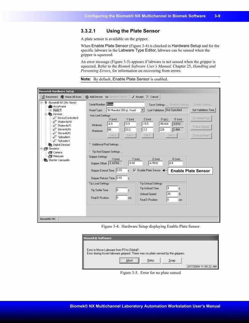
Configuring the Biomek® NX Multichannel in Biomek Software 3-9
Biomek® NX Multichannel Laboratory Automation Workstation User’s Manual
3.3.2.1 Using the Plate SensorA plate sensor is available on the gripper.
When Enable Plate Sensor (Figure 3-4) is checked in Hardware Setup and for the specific labware in the Labware Type Editor, labware can be sensed when the gripper is squeezed.
An error message (Figure 3-5) appears if labware is not sensed when the gripper is squeezed. Refer to the Biomek Software User’s Manual, Chapter 25, Handling and Preventing Errors, for information on recovering from errors.
Note: By default, Enable Plate Sensor is enabled.
Figure 3-4. Hardware Setup displaying Enable Plate Sensor
Figure 3-5. Error for no plate sensed
Enable Plate Sensor
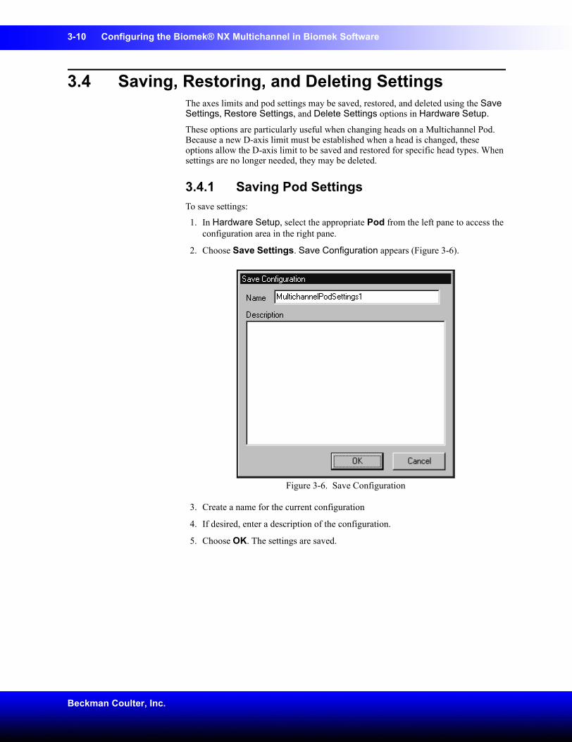
3-10 Configuring the Biomek® NX Multichannel in Biomek Software
Beckman Coulter, Inc.
3.4 Saving, Restoring, and Deleting SettingsThe axes limits and pod settings may be saved, restored, and deleted using the Save Settings, Restore Settings, and Delete Settings options in Hardware Setup.
These options are particularly useful when changing heads on a Multichannel Pod. Because a new D-axis limit must be established when a head is changed, these options allow the D-axis limit to be saved and restored for specific head types. When settings are no longer needed, they may be deleted.
3.4.1 Saving Pod SettingsTo save settings:
1. In Hardware Setup, select the appropriate Pod from the left pane to access the configuration area in the right pane.
2. Choose Save Settings. Save Configuration appears (Figure 3-6).
Figure 3-6. Save Configuration
3. Create a name for the current configuration
4. If desired, enter a description of the configuration.
5. Choose OK. The settings are saved.
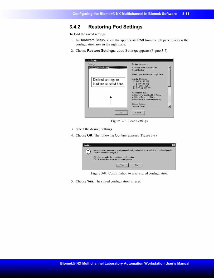
Configuring the Biomek® NX Multichannel in Biomek Software 3-11
Biomek® NX Multichannel Laboratory Automation Workstation User’s Manual
3.4.2 Restoring Pod SettingsTo load the saved settings:
1. In Hardware Setup, select the appropriate Pod from the left pane to access the configuration area in the right pane.
2. Choose Restore Settings. Load Settings appears (Figure 3-7).
Figure 3-7. Load Settings
3. Select the desired settings.
4. Choose OK. The following Confirm appears (Figure 3-8).
Figure 3-8. Confirmation to reset stored configuration
5. Choose Yes. The stored configuration is reset.
Desired settings to load are selected here.
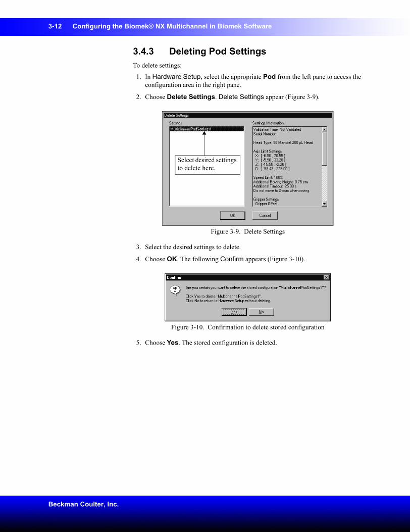
3-12 Configuring the Biomek® NX Multichannel in Biomek Software
Beckman Coulter, Inc.
3.4.3 Deleting Pod SettingsTo delete settings:
1. In Hardware Setup, select the appropriate Pod from the left pane to access the configuration area in the right pane.
2. Choose Delete Settings. Delete Settings appear (Figure 3-9).
Figure 3-9. Delete Settings
3. Select the desired settings to delete.
4. Choose OK. The following Confirm appears (Figure 3-10).
Figure 3-10. Confirmation to delete stored configuration
5. Choose Yes. The stored configuration is deleted.
Select desired settings to delete here.
4-1
Biomek® NX Multichannel Laboratory Automation Workstation User’s Manual
4 Framing Instructions
4.1 OverviewFraming is the procedure of teaching Biomek Software the location of the ALPs and devices positioned on the instrument deck. Biomek Software uses this framing information to move the pod or gripper to the appropriate position to perform liquid-handling operations and manipulate labware.
A Beckman Coulter Service Engineer frames the Biomek NX instrument during system installation. It may be necessary to repeat the framing if:
• ALPs or devices are added, moved, or removed from the deck.
• the head on the Multichannel Pod is changed.
Framing deck positions can be performed automatically using the AccuFrame framing tool, or manually using a piece of labware to visually align the pod to the wells. The gripper may also be framed using the AccuFrame framing tool.
Framing the Biomek NX instrument includes:
• Framing Deck Positions on the Biomek® NX Using AccuFrame (Section 4.2).
• Manually Framing Deck Positions on the Biomek® NX (Section 4.3).
• Framing the Gripper (Section 4.4).
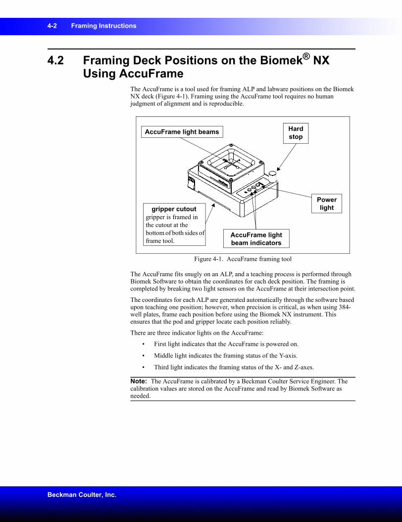
4-2 Framing Instructions
Beckman Coulter, Inc.
4.2 Framing Deck Positions on the Biomek® NX Using AccuFrame
The AccuFrame is a tool used for framing ALP and labware positions on the Biomek NX deck (Figure 4-1). Framing using the AccuFrame tool requires no human judgment of alignment and is reproducible.
Figure 4-1. AccuFrame framing tool
The AccuFrame fits snugly on an ALP, and a teaching process is performed through Biomek Software to obtain the coordinates for each deck position. The framing is completed by breaking two light sensors on the AccuFrame at their intersection point.
The coordinates for each ALP are generated automatically through the software based upon teaching one position; however, when precision is critical, as when using 384-well plates, frame each position before using the Biomek NX instrument. This ensures that the pod and gripper locate each position reliably.
There are three indicator lights on the AccuFrame:
• First light indicates that the AccuFrame is powered on.
• Middle light indicates the framing status of the Y-axis.
• Third light indicates the framing status of the X- and Z-axes.
Note: The AccuFrame is calibrated by a Beckman Coulter Service Engineer. The calibration values are stored on the AccuFrame and read by Biomek Software as needed.
gripper cutoutgripper is framed in the cutout at the bottom of both sides of frame tool.
AccuFrame light beam indicators
Power light
AccuFrame light beams Hard stop
Framing Instructions 4-3
Biomek® NX Multichannel Laboratory Automation Workstation User’s Manual
To frame deck positions of the Biomek NX using AccuFrame, a framing fixture is attached to the head of the Multichannel Pod. When framing multiple position ALPs such as the 1 X 3 Passive ALP, all positions on the ALP should be framed to increase precision.
To frame the deck positions of the Biomek NX, the following operations must be completed:
• Homing All Axes of the Pods (Section 4.2.1).
• Attaching the Framing Fixture to the Pod (Section 4.2.2).
• Installing AccuFrame (Section 4.2.3).
• Framing the Position (Section 4.2.4).
Note: Some ALPs require additional or slightly modified procedures to frame properly. Consult the ALPs User’s Manual for the specific ALP to frame for any special instructions.
Note: Deck positions on the Biomek NX can also be framed by choosing Manual Teach on Position Properties. Manual Teach involves loading tips and visually aligning them with the wells on a piece of labware (refer to Section 4.3, Manually Framing Deck Positions on the Biomek® NX). Manual Teach is useful if specialized or very high density labware is used, or when Auto Teach yields unsatisfactory results. Some ALPs, such as the Positive Position ALP, must be framed manually.
4.2.1 Homing All Axes of the PodsCAUTION: Before selecting OK to home all axes, the following conditions must be met:
• Make sure there is no liquid present in the tips• Make sure there are no disposable tips loaded• Make sure the Framing Probe is NOT installed on the
Multichannel Pod.• Make sure the gripper on the Multichannel Pod is retracted.
Prior to framing the Biomek NX deck, all axes must be homed. Homing the pod gives Biomek NX a point of reference from which to make subsequent moves. Home position is left and back. While it is necessary to home the pod after the Biomek NX instrument is powered on, it is not necessary to home the pod each time the host computer is turned on or the software is accessed.
Note: Home the pod each time the Biomek NX instrument is powered on. When attempting to use the pod, error messages result until the pod is homed.
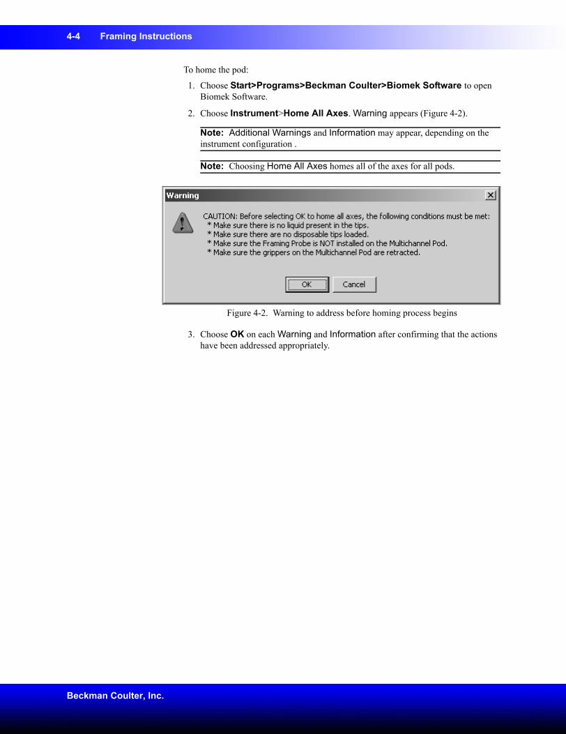
4-4 Framing Instructions
Beckman Coulter, Inc.
To home the pod:
1. Choose Start>Programs>Beckman Coulter>Biomek Software to open Biomek Software.
2. Choose Instrument>Home All Axes. Warning appears (Figure 4-2).
Note: Additional Warnings and Information may appear, depending on the instrument configuration .
Note: Choosing Home All Axes homes all of the axes for all pods.
Figure 4-2. Warning to address before homing process begins
3. Choose OK on each Warning and Information after confirming that the actions have been addressed appropriately.
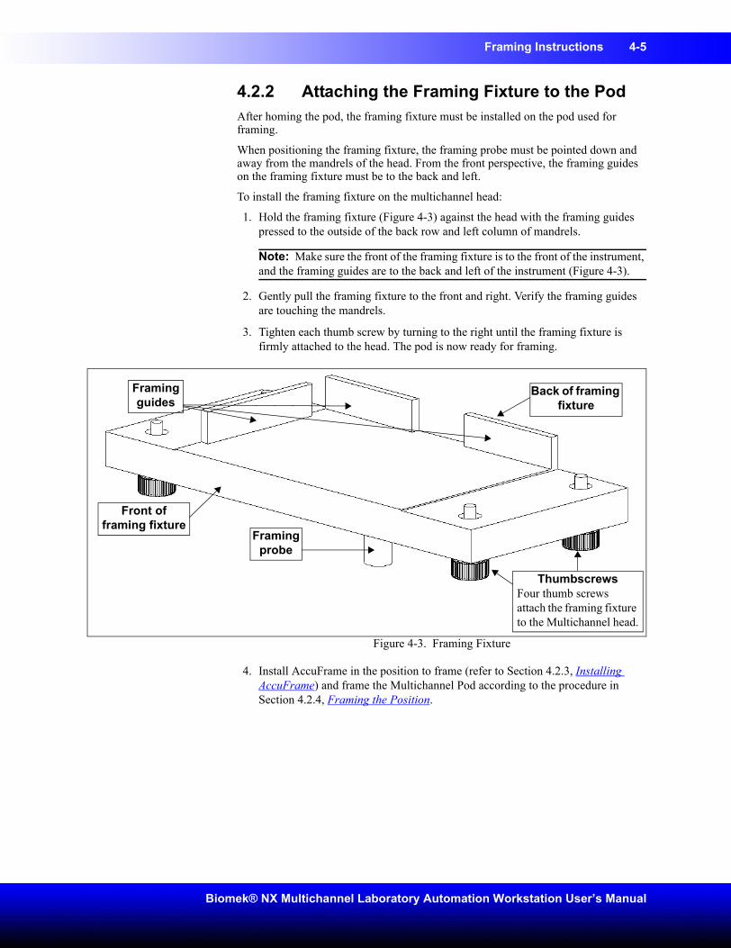
Framing Instructions 4-5
Biomek® NX Multichannel Laboratory Automation Workstation User’s Manual
4.2.2 Attaching the Framing Fixture to the PodAfter homing the pod, the framing fixture must be installed on the pod used for framing.
When positioning the framing fixture, the framing probe must be pointed down and away from the mandrels of the head. From the front perspective, the framing guides on the framing fixture must be to the back and left.
To install the framing fixture on the multichannel head:
1. Hold the framing fixture (Figure 4-3) against the head with the framing guides pressed to the outside of the back row and left column of mandrels.
Note: Make sure the front of the framing fixture is to the front of the instrument, and the framing guides are to the back and left of the instrument (Figure 4-3).
2. Gently pull the framing fixture to the front and right. Verify the framing guides are touching the mandrels.
3. Tighten each thumb screw by turning to the right until the framing fixture is firmly attached to the head. The pod is now ready for framing.
Figure 4-3. Framing Fixture
4. Install AccuFrame in the position to frame (refer to Section 4.2.3, Installing AccuFrame) and frame the Multichannel Pod according to the procedure in Section 4.2.4, Framing the Position.
Framing probe
Framing guides
Front of framing fixture
Back of framing fixture
ThumbscrewsFour thumb screws attach the framing fixture to the Multichannel head.
4-6 Framing Instructions
Beckman Coulter, Inc.
4.2.3 Installing AccuFrame AccuFrame is used during the framing process to frame deck positions. After the framing shaft is attached to the pod and AccuFrame is positioned on the ALP, the framing process is completed through the software.
WARNING: Turn off power to the Biomek NX instrument before attaching or removing AccuFrame from the instrument deck.1. Turn off power to the Biomek NX instrument before connecting the AccuFrame.
2. Plug AccuFrame into an available CAN port on the Biomek NX tower.
WARNING: Make sure the light curtain is not violated by the AccuFrame cable. If the light curtain is violated, the framing process halts immediately.WARNING: Make sure the AccuFrame cable does not interfere with pod movement.3. Turn on power to the Biomek NX instrument.
4. Manually place the AccuFrame onto the ALP position that requires framing by placing the back right corner first and pushing the AccuFrame gently down onto the ALP position.
Note: The deck is usually framed from from left to right, starting at the back left position. However, ALPs may be framed in any order.
5. Make sure that the AccuFrame is fully seated along the posts along the top and right sides of the position.
Note: Some ALPs require a framing adaptor to accommodate using AccuFrame to frame the position. Make sure the correct adaptor is used for each type of ALP. Framing proceeds as normal once the AccuFrame is placed on the appropriate adaptor.
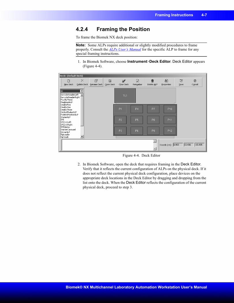
Framing Instructions 4-7
Biomek® NX Multichannel Laboratory Automation Workstation User’s Manual
4.2.4 Framing the PositionTo frame the Biomek NX deck position:
Note: Some ALPs require additional or slightly modified procedures to frame properly. Consult the ALPs User’s Manual for the specific ALP to frame for any special framing instructions.
1. In Biomek Software, choose Instrument>Deck Editor. Deck Editor appears (Figure 4-4).
Figure 4-4. Deck Editor
2. In Biomek Software, open the deck that requires framing in the Deck Editor. Verify that it reflects the current configuration of ALPs on the physical deck. If it does not reflect the current physical deck configuration, place devices on the appropriate deck locations in the Deck Editor by dragging and dropping from the list onto the deck. When the Deck Editor reflects the configuration of the current physical deck, proceed to step 3.
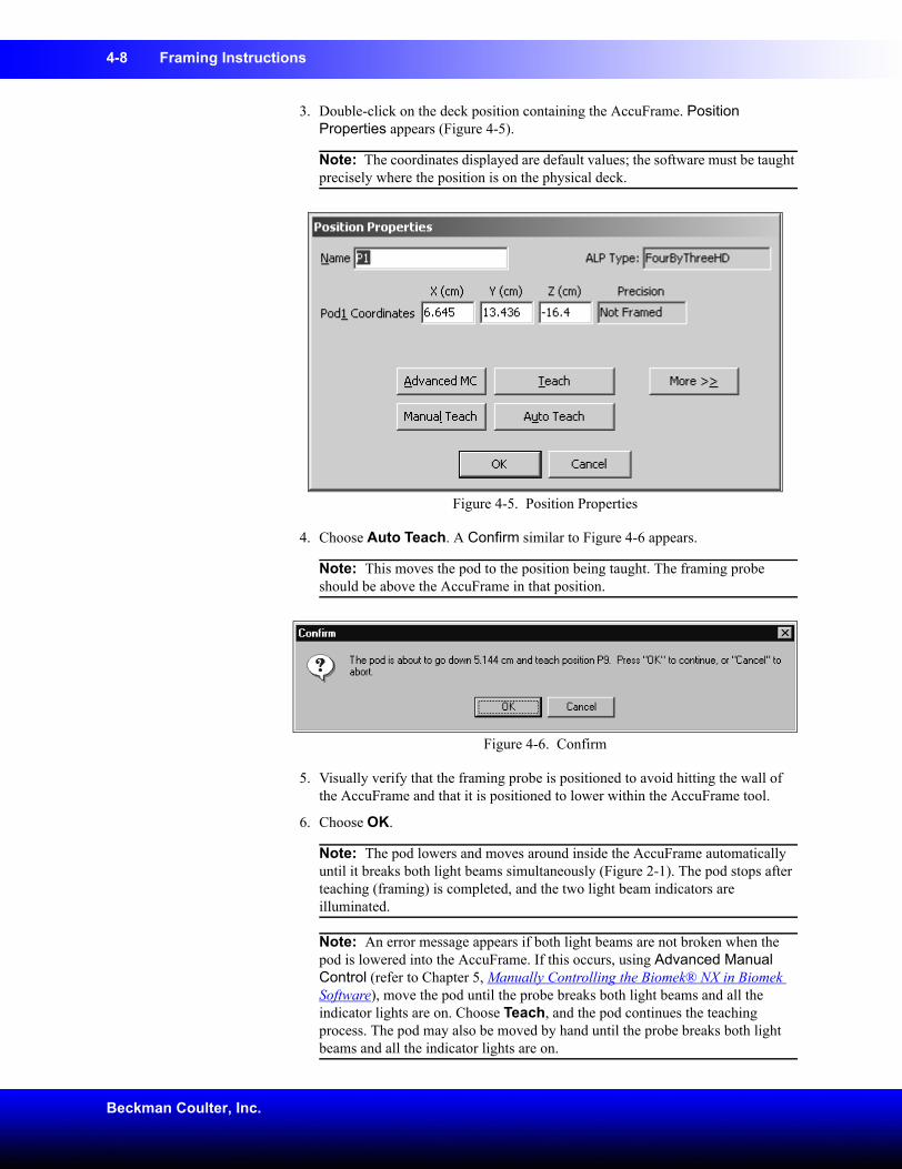
4-8 Framing Instructions
Beckman Coulter, Inc.
3. Double-click on the deck position containing the AccuFrame. Position Properties appears (Figure 4-5).
Note: The coordinates displayed are default values; the software must be taught precisely where the position is on the physical deck.
Figure 4-5. Position Properties
4. Choose Auto Teach. A Confirm similar to Figure 4-6 appears.
Note: This moves the pod to the position being taught. The framing probe should be above the AccuFrame in that position.
Figure 4-6. Confirm
5. Visually verify that the framing probe is positioned to avoid hitting the wall of the AccuFrame and that it is positioned to lower within the AccuFrame tool.
6. Choose OK.
Note: The pod lowers and moves around inside the AccuFrame automatically until it breaks both light beams simultaneously (Figure 2-1). The pod stops after teaching (framing) is completed, and the two light beam indicators are illuminated.
Note: An error message appears if both light beams are not broken when the pod is lowered into the AccuFrame. If this occurs, using Advanced Manual Control (refer to Chapter 5, Manually Controlling the Biomek® NX in Biomek Software), move the pod until the probe breaks both light beams and all the indicator lights are on. Choose Teach, and the pod continues the teaching process. The pod may also be moved by hand until the probe breaks both light beams and all the indicator lights are on.
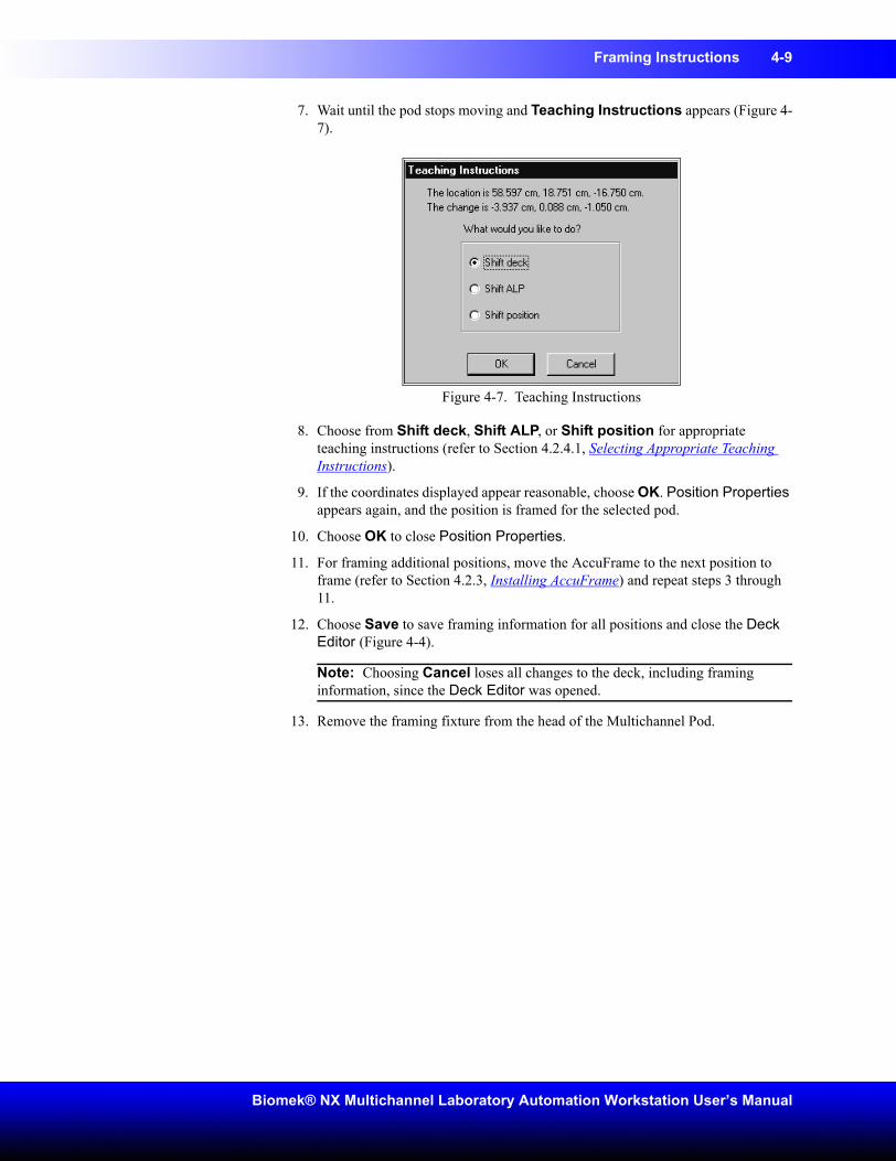
Framing Instructions 4-9
Biomek® NX Multichannel Laboratory Automation Workstation User’s Manual
7. Wait until the pod stops moving and Teaching Instructions appears (Figure 4-7).
Figure 4-7. Teaching Instructions
8. Choose from Shift deck, Shift ALP, or Shift position for appropriate teaching instructions (refer to Section 4.2.4.1, Selecting Appropriate Teaching Instructions).
9. If the coordinates displayed appear reasonable, choose OK. Position Properties appears again, and the position is framed for the selected pod.
10. Choose OK to close Position Properties.
11. For framing additional positions, move the AccuFrame to the next position to frame (refer to Section 4.2.3, Installing AccuFrame) and repeat steps 3 through 11.
12. Choose Save to save framing information for all positions and close the Deck Editor (Figure 4-4).
Note: Choosing Cancel loses all changes to the deck, including framing information, since the Deck Editor was opened.
13. Remove the framing fixture from the head of the Multichannel Pod.
4-10 Framing Instructions
Beckman Coulter, Inc.
4.2.4.1 Selecting Appropriate Teaching InstructionsIn Teaching Instructions (Figure 4-7), the entire deck, a deck position, or an ALP can be shifted by the teaching process. Determine what should be shifted using the following information:
CAUTION: Use Shift deck only before other ALPs or positions are taught. Shift deck shifts all ALPs and positions, resulting in incorrect coordinates if applied to previously framed ALPs and positions.
• Shift deck — shifts all ALPs and positions associated with the deck by the change amounts shown. Choose Shift deck when framing the first location of a new deck. The shift amount required typically is not large, but everything on the deck may need to move 1 cm, for example.
• Shift ALP — shifts the entire ALP and all deck positions associated with the ALP by the change amounts shown. Shift ALP typically is precise enough for using 96-well plates.
• Shift position — shifts only the deck position containing the AccuFrame by the amounts shown. Shift position is the most precise teaching procedure, and it is useful when 384-well microplates are used (especially on larger ALPs, such as the 4x4); otherwise, Shift ALP is usually sufficient.
Note: When framing a multiple-position ALP (1x3, 1x5, 4x3, or 4x4), Shift ALP on the first position, then Shift position on the rest.
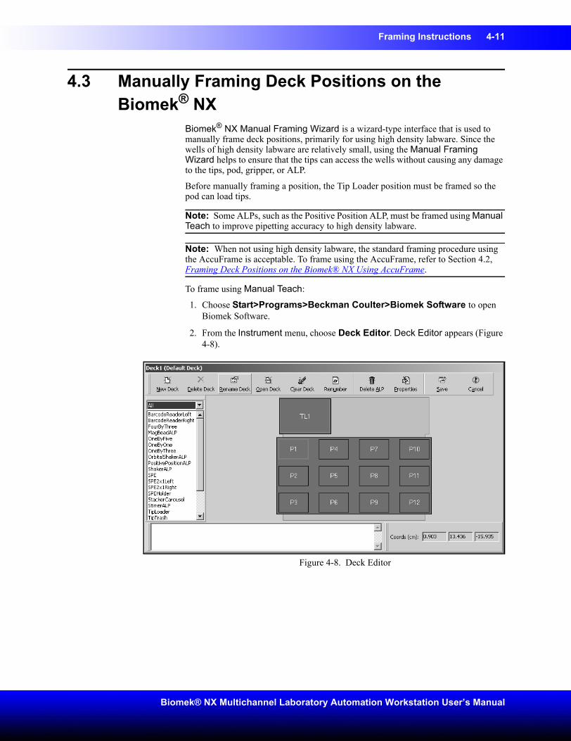
Framing Instructions 4-11
Biomek® NX Multichannel Laboratory Automation Workstation User’s Manual
4.3 Manually Framing Deck Positions on the Biomek® NX
Biomek® NX Manual Framing Wizard is a wizard-type interface that is used to manually frame deck positions, primarily for using high density labware. Since the wells of high density labware are relatively small, using the Manual Framing Wizard helps to ensure that the tips can access the wells without causing any damage to the tips, pod, gripper, or ALP.
Before manually framing a position, the Tip Loader position must be framed so the pod can load tips.
Note: Some ALPs, such as the Positive Position ALP, must be framed using Manual Teach to improve pipetting accuracy to high density labware.
Note: When not using high density labware, the standard framing procedure using the AccuFrame is acceptable. To frame using the AccuFrame, refer to Section 4.2, Framing Deck Positions on the Biomek® NX Using AccuFrame.
To frame using Manual Teach:
1. Choose Start>Programs>Beckman Coulter>Biomek Software to open Biomek Software.
2. From the Instrument menu, choose Deck Editor. Deck Editor appears (Figure 4-8).
Figure 4-8. Deck Editor
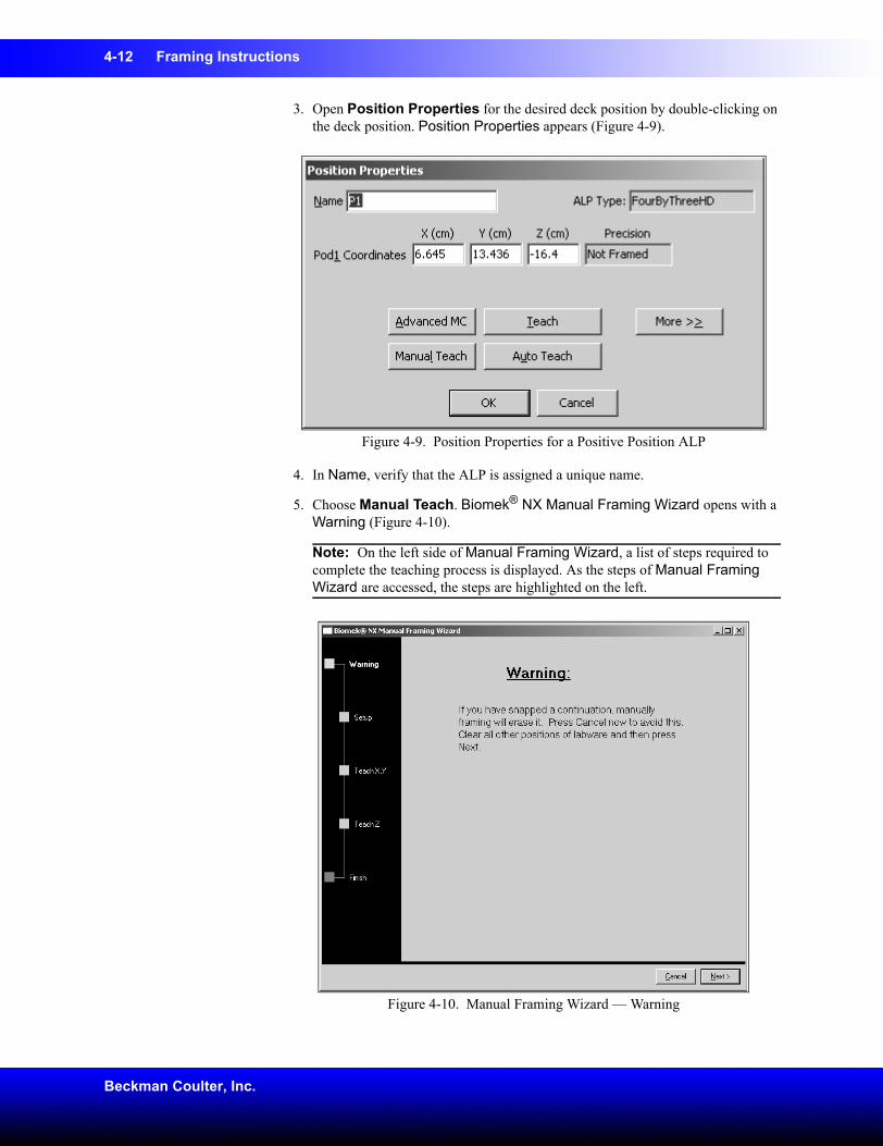
4-12 Framing Instructions
Beckman Coulter, Inc.
3. Open Position Properties for the desired deck position by double-clicking on the deck position. Position Properties appears (Figure 4-9).
Figure 4-9. Position Properties for a Positive Position ALP
4. In Name, verify that the ALP is assigned a unique name.
5. Choose Manual Teach. Biomek® NX Manual Framing Wizard opens with a Warning (Figure 4-10).
Note: On the left side of Manual Framing Wizard, a list of steps required to complete the teaching process is displayed. As the steps of Manual Framing Wizard are accessed, the steps are highlighted on the left.
Figure 4-10. Manual Framing Wizard — Warning
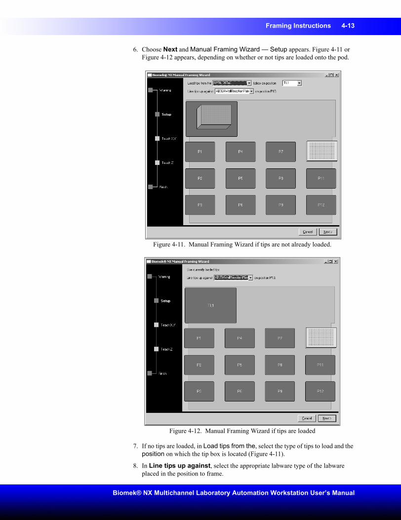
Framing Instructions 4-13
Biomek® NX Multichannel Laboratory Automation Workstation User’s Manual
6. Choose Next and Manual Framing Wizard — Setup appears. Figure 4-11 or Figure 4-12 appears, depending on whether or not tips are loaded onto the pod.
Figure 4-11. Manual Framing Wizard if tips are not already loaded.
Figure 4-12. Manual Framing Wizard if tips are loaded
7. If no tips are loaded, in Load tips from the, select the type of tips to load and the position on which the tip box is located (Figure 4-11).
8. In Line tips up against, select the appropriate labware type of the labware placed in the position to frame.
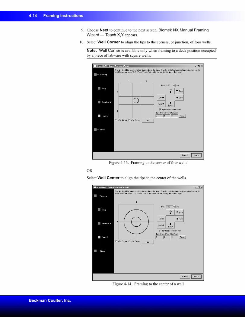
4-14 Framing Instructions
Beckman Coulter, Inc.
9. Choose Next to continue to the next screen. Biomek NX Manual Framing Wizard — Teach X,Y appears.
10. Select Well Corner to align the tips to the corners, or junction, of four wells.
Note: Well Corner is available only when framing to a deck position occupied by a piece of labware with square wells.
Figure 4-13. Framing to the corner of four wells
OR
Select Well Center to align the tips to the center of the wells.
Figure 4-14. Framing to the center of a well
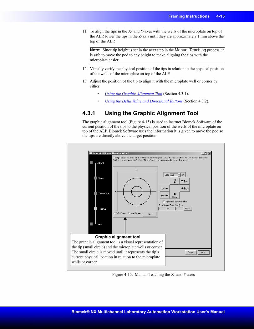
Framing Instructions 4-15
Biomek® NX Multichannel Laboratory Automation Workstation User’s Manual
11. To align the tips in the X- and Y-axes with the wells of the microplate on top of the ALP, lower the tips in the Z-axis until they are approximately 1 mm above the top of the ALP.
Note: Since tip height is set in the next step in the Manual Teaching process, it is safe to move the pod to any height to make aligning the tips with the microplate easier.
12. Visually verify the physical position of the tips in relation to the physical position of the wells of the microplate on top of the ALP.
13. Adjust the position of the tip to align it with the microplate well or corner by either:
• Using the Graphic Alignment Tool (Section 4.3.1).
• Using the Delta Value and Directional Buttons (Section 4.3.2).
4.3.1 Using the Graphic Alignment ToolThe graphic alignment tool (Figure 4-15) is used to instruct Biomek Software of the current position of the tips to the physical position of the wells of the microplate on top of the ALP. Biomek Software uses the information it is given to move the pod so the tips are directly above the target position.
Figure 4-15. Manual Teaching the X- and Y-axes
Graphic alignment toolThe graphic alignment tool is a visual representation of the tip (small circle) and the microplate wells or corner. The small circle is moved until it represents the tip’s current physical location in relation to the microplate wells or corner.
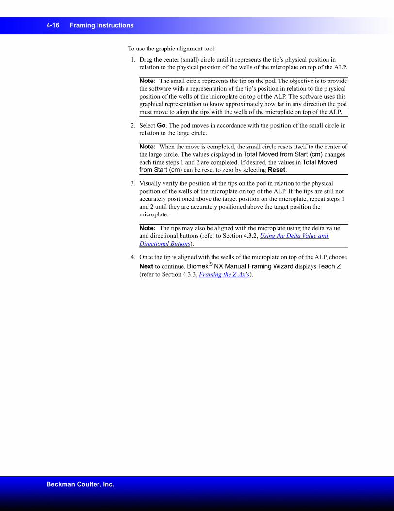
4-16 Framing Instructions
Beckman Coulter, Inc.
To use the graphic alignment tool:
1. Drag the center (small) circle until it represents the tip’s physical position in relation to the physical position of the wells of the microplate on top of the ALP.
Note: The small circle represents the tip on the pod. The objective is to provide the software with a representation of the tip’s position in relation to the physical position of the wells of the microplate on top of the ALP. The software uses this graphical representation to know approximately how far in any direction the pod must move to align the tips with the wells of the microplate on top of the ALP.
2. Select Go. The pod moves in accordance with the position of the small circle in relation to the large circle.
Note: When the move is completed, the small circle resets itself to the center of the large circle. The values displayed in Total Moved from Start (cm) changes each time steps 1 and 2 are completed. If desired, the values in Total Moved from Start (cm) can be reset to zero by selecting Reset.
3. Visually verify the position of the tips on the pod in relation to the physical position of the wells of the microplate on top of the ALP. If the tips are still not accurately positioned above the target position on the microplate, repeat steps 1 and 2 until they are accurately positioned above the target position the microplate.
Note: The tips may also be aligned with the microplate using the delta value and directional buttons (refer to Section 4.3.2, Using the Delta Value and Directional Buttons).
4. Once the tip is aligned with the wells of the microplate on top of the ALP, choose Next to continue. Biomek® NX Manual Framing Wizard displays Teach Z (refer to Section 4.3.3, Framing the Z-Axis).
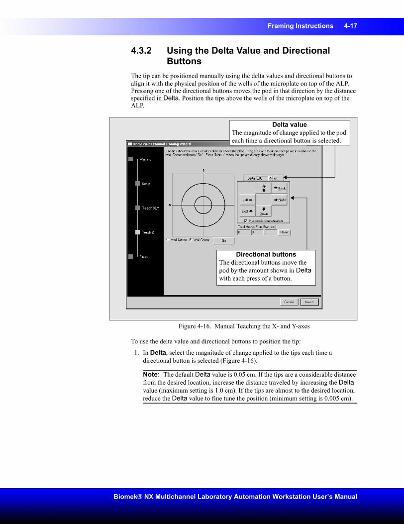
Framing Instructions 4-17
Biomek® NX Multichannel Laboratory Automation Workstation User’s Manual
4.3.2 Using the Delta Value and Directional Buttons
The tip can be positioned manually using the delta values and directional buttons to align it with the physical position of the wells of the microplate on top of the ALP. Pressing one of the directional buttons moves the pod in that direction by the distance specified in Delta. Position the tips above the wells of the microplate on top of the ALP.
Figure 4-16. Manual Teaching the X- and Y-axes
To use the delta value and directional buttons to position the tip:
1. In Delta, select the magnitude of change applied to the tips each time a directional button is selected (Figure 4-16).
Note: The default Delta value is 0.05 cm. If the tips are a considerable distance from the desired location, increase the distance traveled by increasing the Delta value (maximum setting is 1.0 cm). If the tips are almost to the desired location, reduce the Delta value to fine tune the position (minimum setting is 0.005 cm).
Delta valueThe magnitude of change applied to the pod each time a directional button is selected.
Directional buttonsThe directional buttons move the pod by the amount shown in Delta with each press of a button.
4-18 Framing Instructions
Beckman Coulter, Inc.
2. Select the directional button representing the motion required to physically move the tips into position over the wells of the microplate on top of the ALP (Figure 4-16).
Note: Each time a directional button is selected, the pod and tips move the distance specified in Delta in the indicated direction.
Note: The tips can be physically positioned over the wells of a microplate using:
• the directional buttons in Manual Teach.• the directional keys on the keyboard.• the directional keys on the numeric keypad.
The directional buttons displayed in Manual Teach parallel the keys on the numeric keypad. More specifically, Fwd. correlates to the ‘1’ on the numeric keypad, while Down is found on the ‘2’, Left is found on the ‘4’, Right on ‘6’, Up on ‘8’, and Back on ‘9’.
3. Visually verify the position of the tips on the pod in relation to the physical position of the wells of the microplate on top of the ALP. If the tips are still not accurately positioned above the wells of the microplate on top of the ALP, repeat steps 1 and 2 until they are accurately positioned above the target position.
Note: The tips may also be aligned with the target position using the graphic alignment tool (refer to Section 4.3.1, Using the Graphic Alignment Tool).
4. Once the tips are aligned with the target position , choose Next to continue. Biomek® NX Manual Framing Wizard displays Teach Z (refer to Section 4.3.3, Framing the Z-Axis).
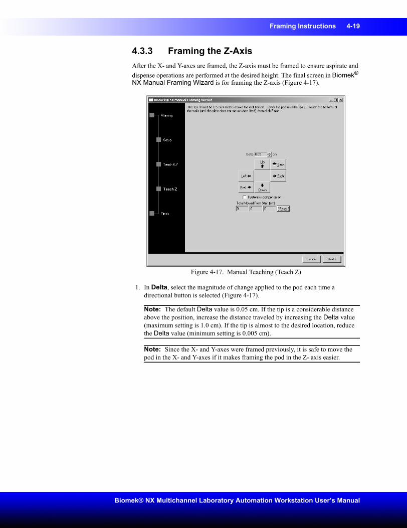
Framing Instructions 4-19
Biomek® NX Multichannel Laboratory Automation Workstation User’s Manual
4.3.3 Framing the Z-AxisAfter the X- and Y-axes are framed, the Z-axis must be framed to ensure aspirate and dispense operations are performed at the desired height. The final screen in Biomek® NX Manual Framing Wizard is for framing the Z-axis (Figure 4-17).
Figure 4-17. Manual Teaching (Teach Z)
1. In Delta, select the magnitude of change applied to the pod each time a directional button is selected (Figure 4-17).
Note: The default Delta value is 0.05 cm. If the tip is a considerable distance above the position, increase the distance traveled by increasing the Delta value (maximum setting is 1.0 cm). If the tip is almost to the desired location, reduce the Delta value (minimum setting is 0.005 cm).
Note: Since the X- and Y-axes were framed previously, it is safe to move the pod in the X- and Y-axes if it makes framing the pod in the Z- axis easier.
4-20 Framing Instructions
Beckman Coulter, Inc.
2. Select the directional button representing the motion required to physically move the pod down until the tip just touches the microplate at the well corner or the bottom of the well.
Note: Each time a directional button is selected, the pod and tips move the distance specified in Delta in the indicated direction.
Note: The tip can be can physically positioned over the labware positioner using:
• the directional buttons in Manual Teach.• the directional keys on the keyboard.• the directional keys on the numeric keypad.
The directional buttons displayed in Manual Teach parallel the keys on the numeric keypad. More specifically, Fwd. correlates to the ‘1’ on the numeric keypad, while Down is found on the ‘2’, Left is found on the ‘4’, Right on ‘6’, Up on ‘8’, and Back on ‘9’.
3. Once the tip is just touching the target position, select Finish. The pod moves up to its maximum height in the Z-axis, Manual Teaching closes, and Position Properties appears (Figure 4-9).
4. Choose OK to save the framing information and close Position Properties.
5. Repeat the procedure to frame additional deck positions using manual teach.
6. Choose Save to save framing information for all positions and close the Deck Editor (Figure 4-8).
Note: Choosing Cancel loses all changes to the deck, including framing information, since the Deck Editor was opened.
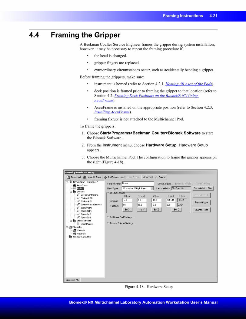
Framing Instructions 4-21
Biomek® NX Multichannel Laboratory Automation Workstation User’s Manual
4.4 Framing the Gripper A Beckman Coulter Service Engineer frames the gripper during system installation; however, it may be necessary to repeat the framing procedure if:
• the head is changed.
• gripper fingers are replaced.
• extraordinary circumstances occur, such as accidentally bending a gripper.
Before framing the grippers, make sure:
• instrument is homed (refer to Section 4.2.1, Homing All Axes of the Pods).
• deck position is framed prior to framing the gripper to that location (refer to Section 4.2, Framing Deck Positions on the Biomek® NX Using AccuFrame).
• AccuFrame is installed on the appropriate position (refer to Section 4.2.3, Installing AccuFrame).
• framing fixture is not attached to the Multichannel Pod.
To frame the grippers:
1. Choose Start>Programs>Beckman Coulter>Biomek Software to start the Biomek Software.
2. From the Instrument menu, choose Hardware Setup. Hardware Setup appears.
3. Choose the Multichannel Pod. The configuration to frame the gripper appears on the right (Figure 4-18).
Figure 4-18. Hardware Setup
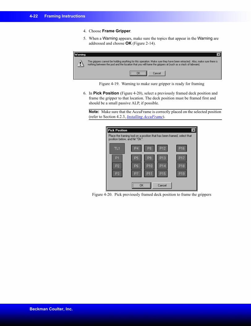
4-22 Framing Instructions
Beckman Coulter, Inc.
4. Choose Frame Gripper.
5. When a Warning appears, make sure the topics that appear in the Warning are addressed and choose OK (Figure 2-14).
Figure 4-19. Warning to make sure gripper is ready for framing
6. In Pick Position (Figure 4-20), select a previously framed deck position and frame the gripper to that location. The deck position must be framed first and should be a small passive ALP, if possible.
Note: Make sure that the AccuFrame is correctly placed on the selected position (refer to Section 4.2.3, Installing AccuFrame).
Figure 4-20. Pick previously framed deck position to frame the grippers
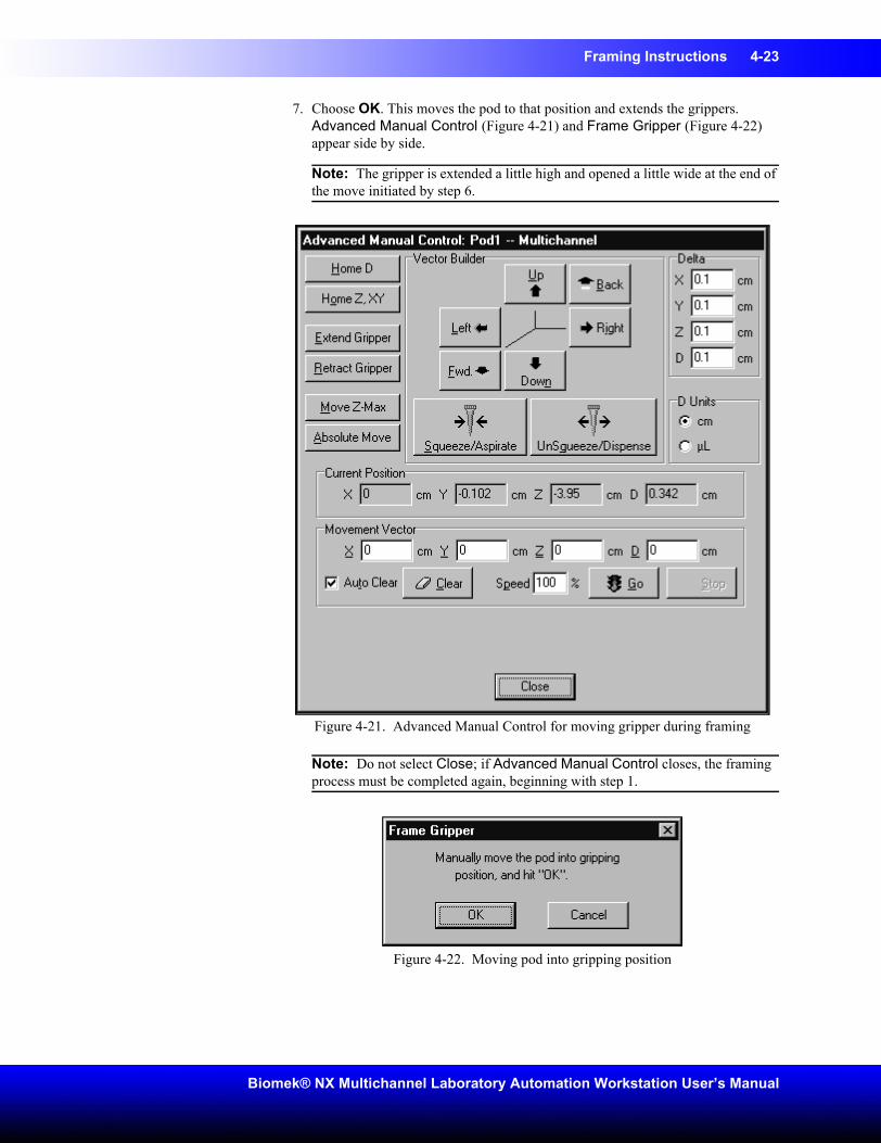
Framing Instructions 4-23
Biomek® NX Multichannel Laboratory Automation Workstation User’s Manual
7. Choose OK. This moves the pod to that position and extends the grippers. Advanced Manual Control (Figure 4-21) and Frame Gripper (Figure 4-22) appear side by side.
Note: The gripper is extended a little high and opened a little wide at the end of the move initiated by step 6.
Figure 4-21. Advanced Manual Control for moving gripper during framing
Note: Do not select Close; if Advanced Manual Control closes, the framing process must be completed again, beginning with step 1.
Figure 4-22. Moving pod into gripping position
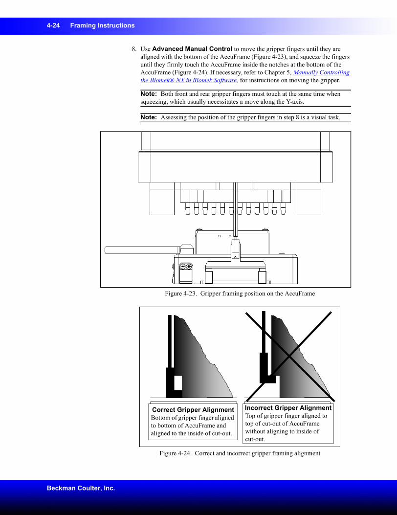
4-24 Framing Instructions
Beckman Coulter, Inc.
8. Use Advanced Manual Control to move the gripper fingers until they are aligned with the bottom of the AccuFrame (Figure 4-23), and squeeze the fingers until they firmly touch the AccuFrame inside the notches at the bottom of the AccuFrame (Figure 4-24). If necessary, refer to Chapter 5, Manually Controlling the Biomek® NX in Biomek Software, for instructions on moving the gripper.
Note: Both front and rear gripper fingers must touch at the same time when squeezing, which usually necessitates a move along the Y-axis.
Note: Assessing the position of the gripper fingers in step 8 is a visual task.
Figure 4-23. Gripper framing position on the AccuFrame
Figure 4-24. Correct and incorrect gripper framing alignment
Correct Gripper AlignmentBottom of gripper finger aligned to bottom of AccuFrame and aligned to the inside of cut-out.
Incorrect Gripper AlignmentTop of gripper finger aligned to top of cut-out of AccuFrame without aligning to inside ofcut-out.
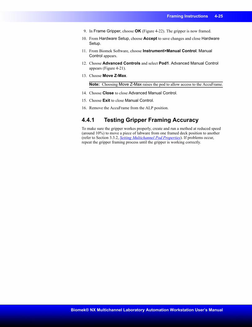
Framing Instructions 4-25
Biomek® NX Multichannel Laboratory Automation Workstation User’s Manual
9. In Frame Gripper, choose OK (Figure 4-22). The gripper is now framed.
10. From Hardware Setup, choose Accept to save changes and close Hardware Setup.
11. From Biomek Software, choose Instrument>Manual Control. Manual Control appears.
12. Choose Advanced Controls and select Pod1. Advanced Manual Control appears (Figure 4-21).
13. Choose Move Z-Max.
Note: Choosing Move Z-Max raises the pod to allow access to the AccuFrame.
14. Choose Close to close Advanced Manual Control.
15. Choose Exit to close Manual Control.
16. Remove the AccuFrame from the ALP position.
4.4.1 Testing Gripper Framing AccuracyTo make sure the gripper workes properly, create and run a method at reduced speed (around 10%) to move a piece of labware from one framed deck position to another (refer to Section 3.3.2, Setting Multichannel Pod Properties). If problems occur, repeat the gripper framing process until the gripper is working correctly.
4-26 Framing Instructions
Beckman Coulter, Inc.
4.5 TroubleshootingPerform the troubleshooting techniques provided in Table 4-1 when necessary.
Note: In the case of any other framing-related problems, contact a Beckman Coulter Service Engineer.
Table 4-1. Troubleshooting FramingIf Then
AccuFrame power light not on Check the CAN connection to make sure the AccuFrame is connected to Biomek NX instrument.
The Y-axis and the X/Z-axes Light Beams cannot be broken when moving a finger around the interior of AccuFrame
Make sure the AccuFrame is receiving power.
One or both beam indicator lights on AccuFrame stay on when no objects are breaking the light beams
There is most likely an internal obstruction to sensors. Call a Beckman Coulter Service Engineer.
5-1
Biomek® NX Multichannel Laboratory Automation Workstation User’s Manual
5 Manually Controlling the Biomek® NX in Biomek Software
5.1 OverviewManual Control and Advanced Manual Control are used to control:
• Movement of the pod
• Gripper independently of a method.
• Pod when teaching the deck, framing the grippers, and recovering from errors.
• Tip Loader and other ALPs independently of a method
Note: Refer to the ALPs User’s Manual for information on manually controlling specific ALPs.
The sections in this chapter include:
• Using Manual Control (Section 5.3)
• Using Advanced Manual Control (Section 5.4)
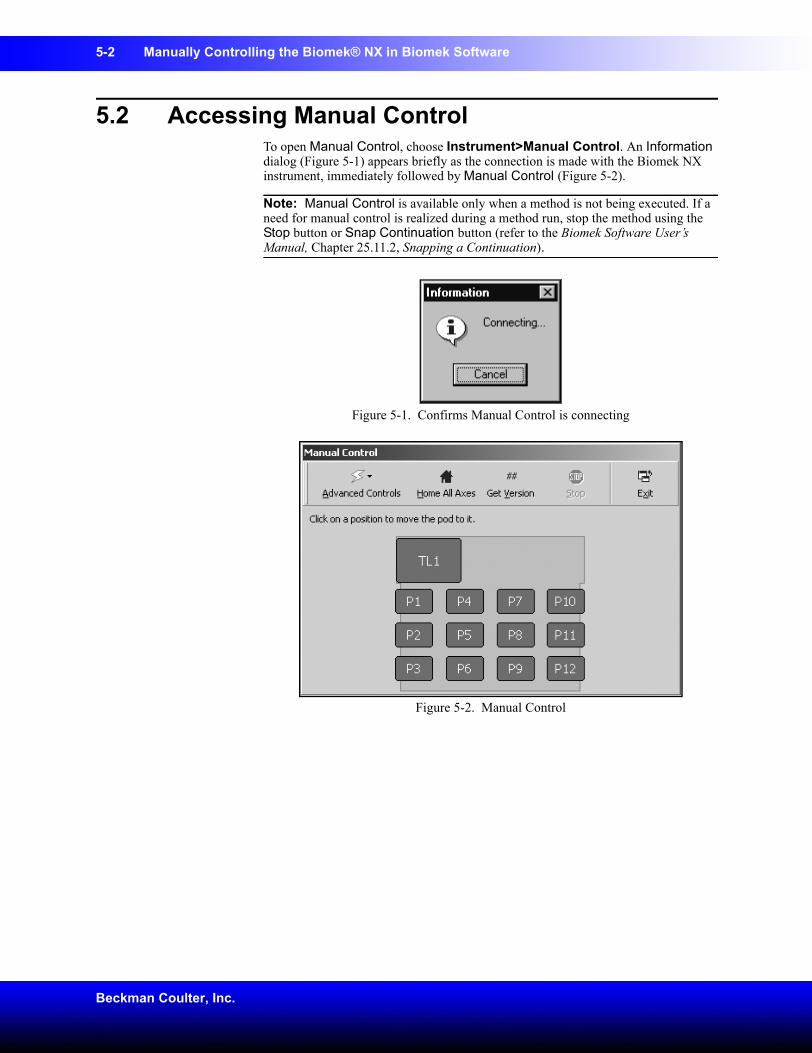
5-2 Manually Controlling the Biomek® NX in Biomek Software
Beckman Coulter, Inc.
5.2 Accessing Manual ControlTo open Manual Control, choose Instrument>Manual Control. An Information dialog (Figure 5-1) appears briefly as the connection is made with the Biomek NX instrument, immediately followed by Manual Control (Figure 5-2).
Note: Manual Control is available only when a method is not being executed. If a need for manual control is realized during a method run, stop the method using the Stop button or Snap Continuation button (refer to the Biomek Software User’s Manual, Chapter 25.11.2, Snapping a Continuation).
Figure 5-1. Confirms Manual Control is connecting
Figure 5-2. Manual Control
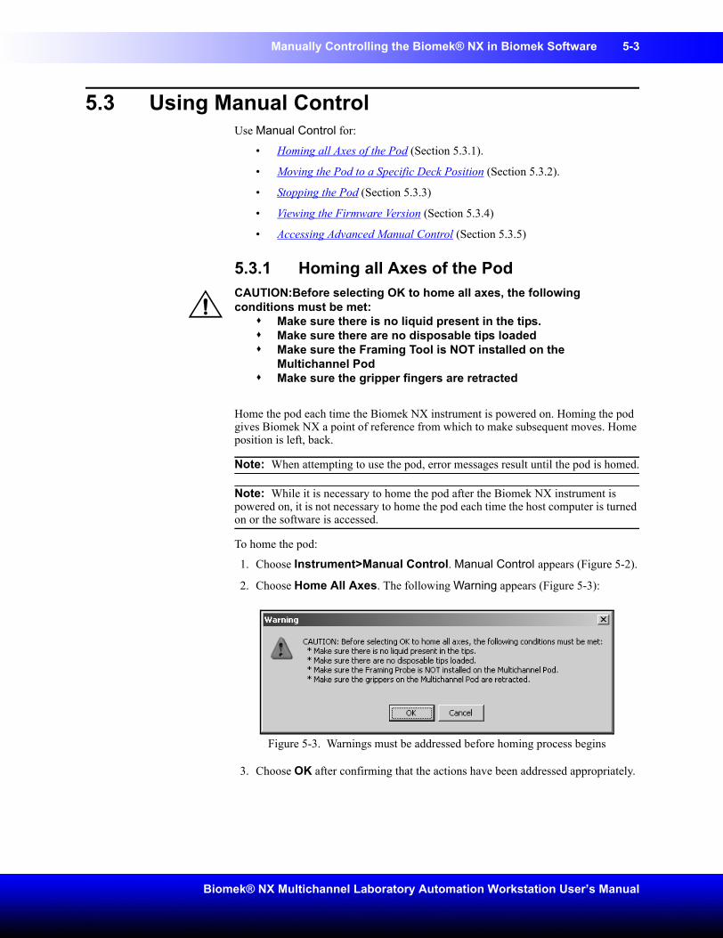
Manually Controlling the Biomek® NX in Biomek Software 5-3
Biomek® NX Multichannel Laboratory Automation Workstation User’s Manual
5.3 Using Manual ControlUse Manual Control for:
• Homing all Axes of the Pod (Section 5.3.1).
• Moving the Pod to a Specific Deck Position (Section 5.3.2).
• Stopping the Pod (Section 5.3.3)
• Viewing the Firmware Version (Section 5.3.4)
• Accessing Advanced Manual Control (Section 5.3.5)
5.3.1 Homing all Axes of the PodCAUTION:Before selecting OK to home all axes, the following conditions must be met:
Make sure there is no liquid present in the tips.Make sure there are no disposable tips loadedMake sure the Framing Tool is NOT installed on the Multichannel PodMake sure the gripper fingers are retracted
Home the pod each time the Biomek NX instrument is powered on. Homing the pod gives Biomek NX a point of reference from which to make subsequent moves. Home position is left, back.
Note: When attempting to use the pod, error messages result until the pod is homed.
Note: While it is necessary to home the pod after the Biomek NX instrument is powered on, it is not necessary to home the pod each time the host computer is turned on or the software is accessed.
To home the pod:
1. Choose Instrument>Manual Control. Manual Control appears (Figure 5-2).
2. Choose Home All Axes. The following Warning appears (Figure 5-3):
Figure 5-3. Warnings must be addressed before homing process begins
3. Choose OK after confirming that the actions have been addressed appropriately.
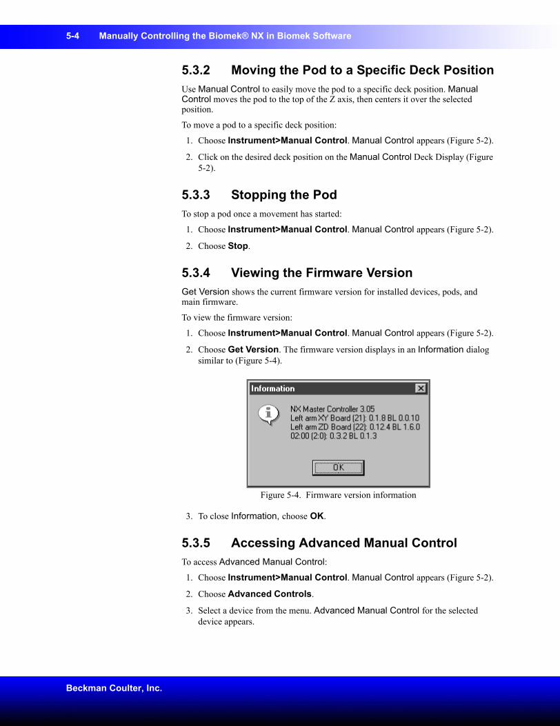
5-4 Manually Controlling the Biomek® NX in Biomek Software
Beckman Coulter, Inc.
5.3.2 Moving the Pod to a Specific Deck PositionUse Manual Control to easily move the pod to a specific deck position. Manual Control moves the pod to the top of the Z axis, then centers it over the selected position.
To move a pod to a specific deck position:
1. Choose Instrument>Manual Control. Manual Control appears (Figure 5-2).
2. Click on the desired deck position on the Manual Control Deck Display (Figure 5-2).
5.3.3 Stopping the PodTo stop a pod once a movement has started:
1. Choose Instrument>Manual Control. Manual Control appears (Figure 5-2).
2. Choose Stop.
5.3.4 Viewing the Firmware VersionGet Version shows the current firmware version for installed devices, pods, and main firmware.
To view the firmware version:
1. Choose Instrument>Manual Control. Manual Control appears (Figure 5-2).
2. Choose Get Version. The firmware version displays in an Information dialog similar to (Figure 5-4).
Figure 5-4. Firmware version information
3. To close Information, choose OK.
5.3.5 Accessing Advanced Manual ControlTo access Advanced Manual Control:
1. Choose Instrument>Manual Control. Manual Control appears (Figure 5-2).
2. Choose Advanced Controls.
3. Select a device from the menu. Advanced Manual Control for the selected device appears.
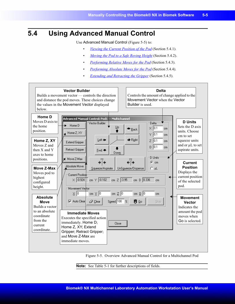
Manually Controlling the Biomek® NX in Biomek Software 5-5
Biomek® NX Multichannel Laboratory Automation Workstation User’s Manual
5.4 Using Advanced Manual Control Use Advanced Manual Control (Figure 5-5) to:
• Viewing the Current Position of the Pod (Section 5.4.1).
• Moving the Pod to a Safe Roving Height (Section 5.4.2).
• Performing Relative Moves for the Pod (Section 5.4.3).
• Performing Absolute Moves for the Pod (Section 5.4.4).
• Extending and Retracting the Gripper (Section 5.4.5).
Figure 5-5. Overview Advanced Manual Control for a Multichannel Pod
Note: See Table 5-1 for further descriptions of fields.
Vector BuilderBuilds a movement vector — controls the direction and distance the pod moves. These choices change the values in the Movement Vector displayed below.
DeltaControls the amount of change applied to the Movement Vector when the Vector Builder is used.
Immediate MovesExecutes the specified action immediately. Home D; Home Z, XY; Extend Gripper; Retract Gripper; and Move Z-Max are immediate moves.
Movement Vector
Indicates the amount the pod moves when Go is selected.
Absolute Move
Builds a vector to an absolute coordinate from the current coordinate.
Current Position
Displays the current position of the selected pod.
D UnitsSets the D axis units. Choose cm to set squeeze units and or µL to set aspirate units.
Home DMoves D axis to the home position.
Home Z, XYMoves Z and then X and Y axes to home positions.
Move Z-MaxMoves pod to highest configured height.
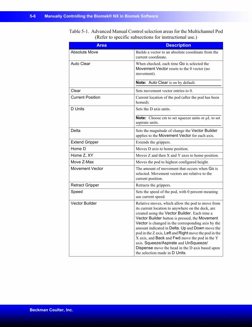
5-6 Manually Controlling the Biomek® NX in Biomek Software
Beckman Coulter, Inc.
Table 5-1. Advanced Manual Control selection areas for the Multichannel Pod(Refer to specific subsections for instructional use.)Area Description
Absolute Move Builds a vector to an absolute coordinate from the current coordinate.
Auto Clear When checked, each time Go is selected the Movement Vector resets to the 0 vector (no movement).
Note: Auto Clear is on by default.
Clear Sets movement vector entries to 0.Current Position Current location of the pod (after the pod has been
homed).D Units Sets the D axis units.
Note: Choose cm to set squeeze units or µL to set aspirate units.
Delta Sets the magnitude of change the Vector Builder applies to the Movement Vector for each axis.
Extend Gripper Extends the grippers.Home D Moves D axis to home position.Home Z, XY Moves Z and then X and Y axes to home position.Move Z-Max Moves the pod to highest configured height.Movement Vector The amount of movement that occurs when Go is
selected. Movement vectors are relative to the current position.
Retract Gripper Retracts the grippers.Speed Sets the speed of the pod, with 0 percent meaning
use current speed.Vector Builder Relative moves, which allow the pod to move from
its current location to anywhere on the deck, are created using the Vector Builder. Each time a Vector Builder button is pressed, the Movement Vector is changed in the corresponding axis by the amount indicated in Delta. Up and Down move the pod in the Z axis, Left and Right move the pod in the X axis, and Back and Fwd move the pod in the Y axis. Squeeze/Aspirate and UnSqueeze/Dispense move the head in the D axis based upon the selection made in D Units.
Manually Controlling the Biomek® NX in Biomek Software 5-7
Biomek® NX Multichannel Laboratory Automation Workstation User’s Manual
5.4.1 Viewing the Current Position of the PodThe current position of the pod is displayed as four coordinates. Each axis coordinate is the distance from the home position.
X, Y, and Z are displayed in centimeters. The D-axis is displayed in either centimeters (cm) or microliters (µL). (Refer to the description for D Units in Table 5-1.)
To view the current position of a pod:
1. Choose Instrument>Manual Control. Manual Control appears (Figure 5-2).
2. Choose Advanced Controls.
3. Select Pod1. Advanced Manual Control for the pod appears (Figure 5-5). The current position is shown in Current Position.
4. Choose Close to close Advanced Manual Control.
5. Choose Exit to close Manual Control.
5.4.2 Moving the Pod to a Safe Roving HeightUse Move Z-Max in Advanced Manual Control to move the pod to its highest configured height. This helps to avoid collisions when moving the pod around the deck manually.
Note: The possibility of collisions is not completely eliminated by this command; for example, if the gripper is extended and holding a microplate, and the pod is moved over a tip box on a tiploader, a collision could occur.
1. Choose Instrument>Manual Control. Manual Control appears (Figure 5-2).
2. Choose Advanced Controls.
3. Select Pod1. Advanced Manual Control for the pod appears (Figure 5-5).
4. Choose Move Z-Max.
5. Choose Close to close Advanced Manual Control.
6. Choose Exit to close Manual Control.
5.4.3 Performing Relative Moves for the PodRelative moves allow the pod to move from its current location to anywhere on the deck. Relative moves are created in the Vector Builder using the Delta values, or the vector can be manually edited.
Note: Use Auto Clear when the values in the Movement Vector fields must be reset to zero after the move is performed. Turn off Auto Clear to retain the values after the move has occurred. Choose Clear to set the values back to zero at any time.
To move a pod relative to its current position:
1. Choose Instrument>Manual Control. Manual Control appears (Figure 5-2).
2. Choose Advanced Controls.
3. Select Pod1. Advanced Manual Control for the pod appears (Figure 5-5).
4. Choose Clear to change the Movement Vector values to 0.
5-8 Manually Controlling the Biomek® NX in Biomek Software
Beckman Coulter, Inc.
5. Enter the desired X, Y, Z, and D values in Movement Vector.
OR
Set the Delta values as desired (refer to Section 5.4.3.1, Setting Delta Values for the Pod) and click the appropriate buttons on Vector Builder (refer to Section 5.4.3.2, Understanding and Using the Vector Builder), until the desired values appear in Movement Vector.
Note: Hold the button down to quickly add Delta value to the Movement Vector.
Note: Positive values move the pod to the right (X), toward the front of the deck (Y), up (Z) and squeeze/aspirate (D). Negative values move the pod to the left (X), towards the back of the deck (Y), down (Z) and unsqueeze/dispense (D).
Note: Minimum and Maximum X, Y, Z, and D values displayed in Hardware Setup indicate how far the pod is able to move. These values are also displayed as a tool tip when hovering over the fields in Movement Vectors.
6. Enter a value in Speed to specify the percent of the pod’s maximum speed.
7. Choose Go. The pod moves from its current position to a new position by the values displayed in the Movement Vector. The new position is displayed in Current Position.
8. Choose Close to close Advanced Manual Control.
9. Choose Exit to close Manual Control.
5.4.3.1 Setting Delta Values for the PodA Delta value is the amount of change in an axis that is applied to the Movement Vector when a button in the Vector Builder is pressed. For example, if the Delta value for X is 3, each time Right is clicked in the Vector Builder, 3 cm is added to the X axis of the Movement Vector.
Note: The move does not occur until Go is selected in the Movement Vector area of Advanced Manual Control.
To set Delta values:
1. Choose Instrument>Manual Control. Manual Control appears (Figure 5-2).
2. Choose Advanced Controls.
3. Select Pod1. Advanced Manual Control for the pod appears (Figure 5-5).
4. Enter a value in X, Y, Z, and D to set the Delta value for each axis.
5. In D Units, select cm or µL.
6. Choose Close to close Advanced Manual Control.
7. Choose Exit to close Manual Control.
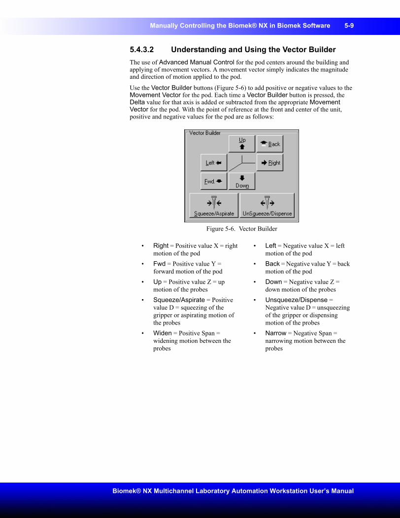
Manually Controlling the Biomek® NX in Biomek Software 5-9
Biomek® NX Multichannel Laboratory Automation Workstation User’s Manual
5.4.3.2 Understanding and Using the Vector BuilderThe use of Advanced Manual Control for the pod centers around the building and applying of movement vectors. A movement vector simply indicates the magnitude and direction of motion applied to the pod.
Use the Vector Builder buttons (Figure 5-6) to add positive or negative values to the Movement Vector for the pod. Each time a Vector Builder button is pressed, the Delta value for that axis is added or subtracted from the appropriate Movement Vector for the pod. With the point of reference at the front and center of the unit, positive and negative values for the pod are as follows:
Figure 5-6. Vector Builder
• Right = Positive value X = right motion of the pod
• Left = Negative value X = left motion of the pod
• Fwd = Positive value Y = forward motion of the pod
• Back = Negative value Y = back motion of the pod
• Up = Positive value Z = up motion of the probes
• Down = Negative value Z = down motion of the probes
• Squeeze/Aspirate = Positive value D = squeezing of the gripper or aspirating motion of the probes
• Unsqueeze/Dispense = Negative value D = unsqueezing of the gripper or dispensing motion of the probes
• Widen = Positive Span = widening motion between the probes
• Narrow = Negative Span = narrowing motion between the probes
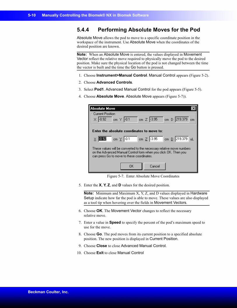
5-10 Manually Controlling the Biomek® NX in Biomek Software
Beckman Coulter, Inc.
5.4.4 Performing Absolute Moves for the PodAbsolute Move allows the pod to move to a specific coordinate position in the workspace of the instrument. Use Absolute Move when the coordinates of the desired position are known.
Note: When an Absolute Move is entered, the values displayed in Movement Vector reflect the relative move required to physically move the pod to the desired position. Make sure the physical location of the pod is not changed between the time the vector is built and the time the Go button is pressed.
1. Choose Instrument>Manual Control. Manual Control appears (Figure 5-2).
2. Choose Advanced Controls.
3. Select Pod1. Advanced Manual Control for the pod appears (Figure 5-5).
4. Choose Absolute Move. Absolute Move appears (Figure 5-7)).
Figure 5-7. Enter Absolute Move Coordinates
5. Enter the X, Y, Z, and D values for the desired position.
Note: Minimum and Maximum X, Y, Z, and D values displayed in Hardware Setup indicate how far the pod is able to move. These values are also displayed as a tool tip when hovering over the fields in Movement Vectors.
6. Choose OK. The Movement Vector changes to reflect the necessaryrelative move.
7. Enter a value in Speed to specify the percent of the pod’s maximum speed to use for the move.
8. Choose Go. The pod moves from its current position to a specified absoluteposition. The new position is displayed in Current Position.
9. Choose Close to close Advanced Manual Control.
10. Choose Exit to close Manual Control
Manually Controlling the Biomek® NX in Biomek Software 5-11
Biomek® NX Multichannel Laboratory Automation Workstation User’s Manual
5.4.5 Extending and Retracting the Gripper Use Advanced Manual Control to extend or retract the gripper when changing the head on the pod.
CAUTION: Select Move Z-Max to move the pod to its highest point before extending the gripper. To avoid breaking labware or bending the gripper fingers, make sure the gripper fingers will not hit any labware when extended.CAUTION: Do not retract gripper when it is holding labware.
From Advanced Manual Control for the pod:
• Choose Extend Gripper to extend the gripper.
• Choose Retract Gripper to retract the gripper.

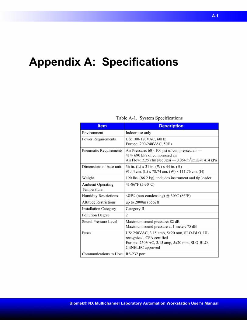
A-1
Biomek® NX Multichannel Laboratory Automation Workstation User’s Manual
Appendix A: Specifications
Table A-1. System SpecificationsItem Description
Environment Indoor use onlyPower Requirements US: 100-120VAC, 60Hz
Europe: 200-240VAC, 50HzPneumatic Requirements Air Pressure: 60 - 100 psi of compressed air —
414- 690 kPa of compressed airAir Flow: 2.25 cfm @ 60 psi — 0.064 m3/min @ 414 kPa
Dimensions of base unit: 36 in. (L) x 31 in. (W) x 44 in. (H)91.44 cm. (L) x 78.74 cm. (W) x 111.76 cm. (H)
Weight 190 lbs. (86.2 kg), includes instrument and tip loaderAmbient Operating Temperature
41-86°F (5-30°C)
Humidity Restrictions <85% (non-condensing) @ 30°C (86°F)Altitude Restrictions up to 2000m (6562ft)Installation Category Category IIPollution Degree 2Sound Pressure Level Maximum sound pressure: 82 dB
Maximum sound pressure at 1 meter: 75 dBFuses US: 250VAC, 3.15 amp, 5x20 mm, SLO-BLO, UL
recognized, CSA certifiedEurope: 250VAC, 3.15 amp, 5x20 mm, SLO-BLO, CENELEC approved
Communications to Host RS-232 port
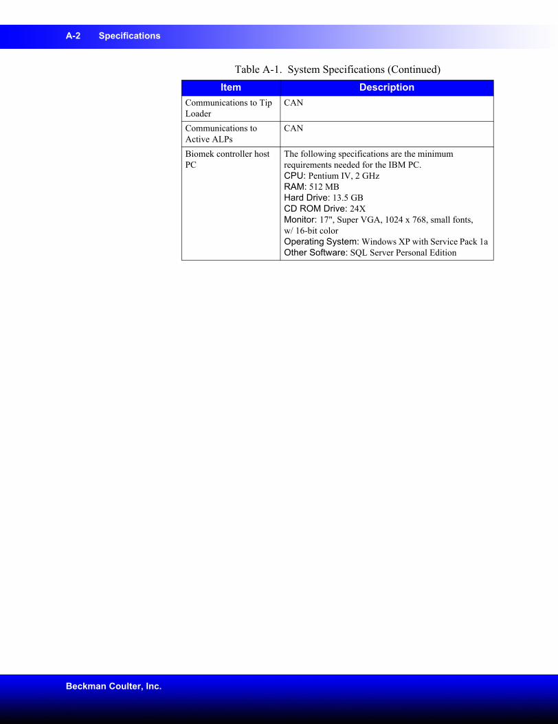
A-2 Specifications
Beckman Coulter, Inc.
Communications to Tip Loader
CAN
Communications to Active ALPs
CAN
Biomek controller host PC
The following specifications are the minimum requirements needed for the IBM PC.CPU: Pentium IV, 2 GHzRAM: 512 MBHard Drive: 13.5 GBCD ROM Drive: 24XMonitor: 17", Super VGA, 1024 x 768, small fonts, w/ 16-bit colorOperating System: Windows XP with Service Pack 1a Other Software: SQL Server Personal Edition
Table A-1. System Specifications (Continued)Item Description
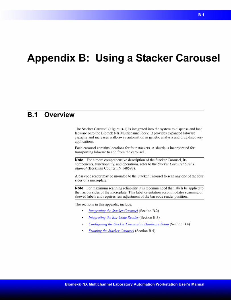
B-1
Biomek® NX Multichannel Laboratory Automation Workstation User’s Manual
Appendix B: Using a Stacker Carousel
B.1 Overview
The Stacker Carousel (Figure B-1) is integrated into the system to dispense and load labware onto the Biomek NX Multichannel deck. It provides expanded labware capacity and increases walk-away automation in genetic analysis and drug discovery applications.
Each carousel contains locations for four stackers. A shuttle is incorporated for transporting labware to and from the carousel.
Note: For a more comprehensive description of the Stacker Carousel, its components, functionality, and operations, refer to the Stacker Carousel User’s Manual (Beckman Coulter PN 148598).
A bar code reader may be mounted to the Stacker Carousel to scan any one of the four sides of a microplate.
Note: For maximum scanning reliability, it is recommended that labels be applied to the narrow sides of the microplate. This label orientation accommodates scanning of skewed labels and requires less adjustment of the bar code reader position.
The sections in this appendix include:
• Integrating the Stacker Carousel (Section B.2)
• Integrating the Bar Code Reader (Section B.3)
• Configuring the Stacker Carousel in Hardware Setup (Section B.4)
• Framing the Stacker Carousel (Section B.5)
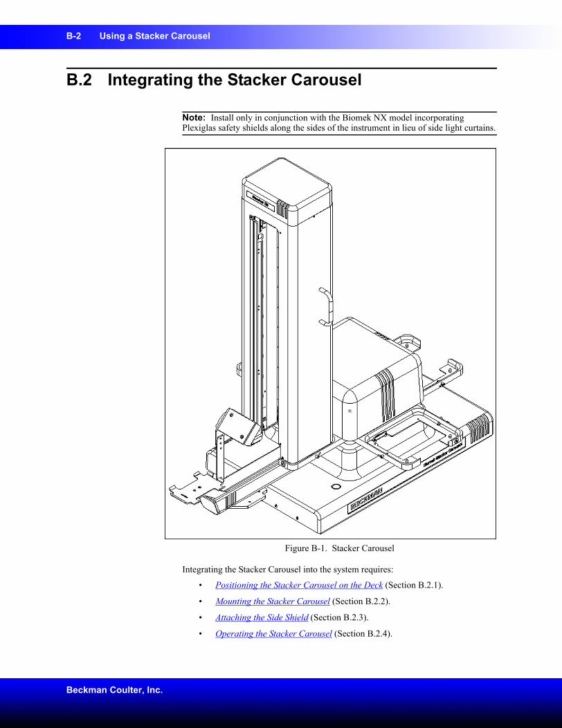
B-2 Using a Stacker Carousel
Beckman Coulter, Inc.
B.2 Integrating the Stacker Carousel
Note: Install only in conjunction with the Biomek NX model incorporating Plexiglas safety shields along the sides of the instrument in lieu of side light curtains.
Figure B-1. Stacker Carousel
Integrating the Stacker Carousel into the system requires:
• Positioning the Stacker Carousel on the Deck (Section B.2.1).
• Mounting the Stacker Carousel (Section B.2.2).
• Attaching the Side Shield (Section B.2.3).
• Operating the Stacker Carousel (Section B.2.4).
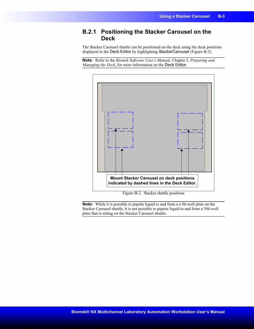
Using a Stacker Carousel B-3
Biomek® NX Multichannel Laboratory Automation Workstation User’s Manual
B.2.1 Positioning the Stacker Carousel on the Deck
The Stacker Carousel shuttle can be positioned on the deck using the deck positions displayed in the Deck Editor by highlighting StackerCarousel (Figure B-2).
Note: Refer to the Biomek Software User’s Manual, Chapter 5, Preparing and Managing the Deck, for more information on the Deck Editor.
Figure B-2. Stacker shuttle positions
Note: While it is possible to pipette liquid to and from a a 96-well plate on the Stacker Carousel shuttle, it is not possible to pipette liquid to and from a 386-well plate that is sitting on the Stacker Carousel shuttle.
Mount Stacker Carousel on deck positions indicated by dashed lines in the Deck Editor.
B-4 Using a Stacker Carousel
Beckman Coulter, Inc.
To position the Stacker Carousel:
Position the Stacker Carousel outside the Biomek NX deck (Figure B-3).
Figure B-3. Stacker Carousel integration
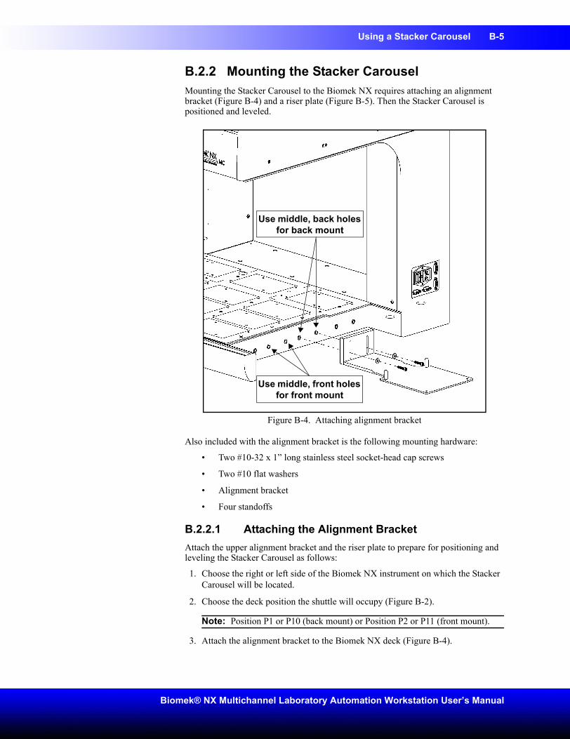
Using a Stacker Carousel B-5
Biomek® NX Multichannel Laboratory Automation Workstation User’s Manual
B.2.2 Mounting the Stacker CarouselMounting the Stacker Carousel to the Biomek NX requires attaching an alignment bracket (Figure B-4) and a riser plate (Figure B-5). Then the Stacker Carousel is positioned and leveled.
Figure B-4. Attaching alignment bracket
Also included with the alignment bracket is the following mounting hardware:
• Two #10-32 x 1” long stainless steel socket-head cap screws
• Two #10 flat washers
• Alignment bracket
• Four standoffs
B.2.2.1 Attaching the Alignment BracketAttach the upper alignment bracket and the riser plate to prepare for positioning and leveling the Stacker Carousel as follows:
1. Choose the right or left side of the Biomek NX instrument on which the Stacker Carousel will be located.
2. Choose the deck position the shuttle will occupy (Figure B-2).
Note: Position P1 or P10 (back mount) or Position P2 or P11 (front mount).
3. Attach the alignment bracket to the Biomek NX deck (Figure B-4).
Use middle, back holes for back mount
Use middle, front holes for front mount
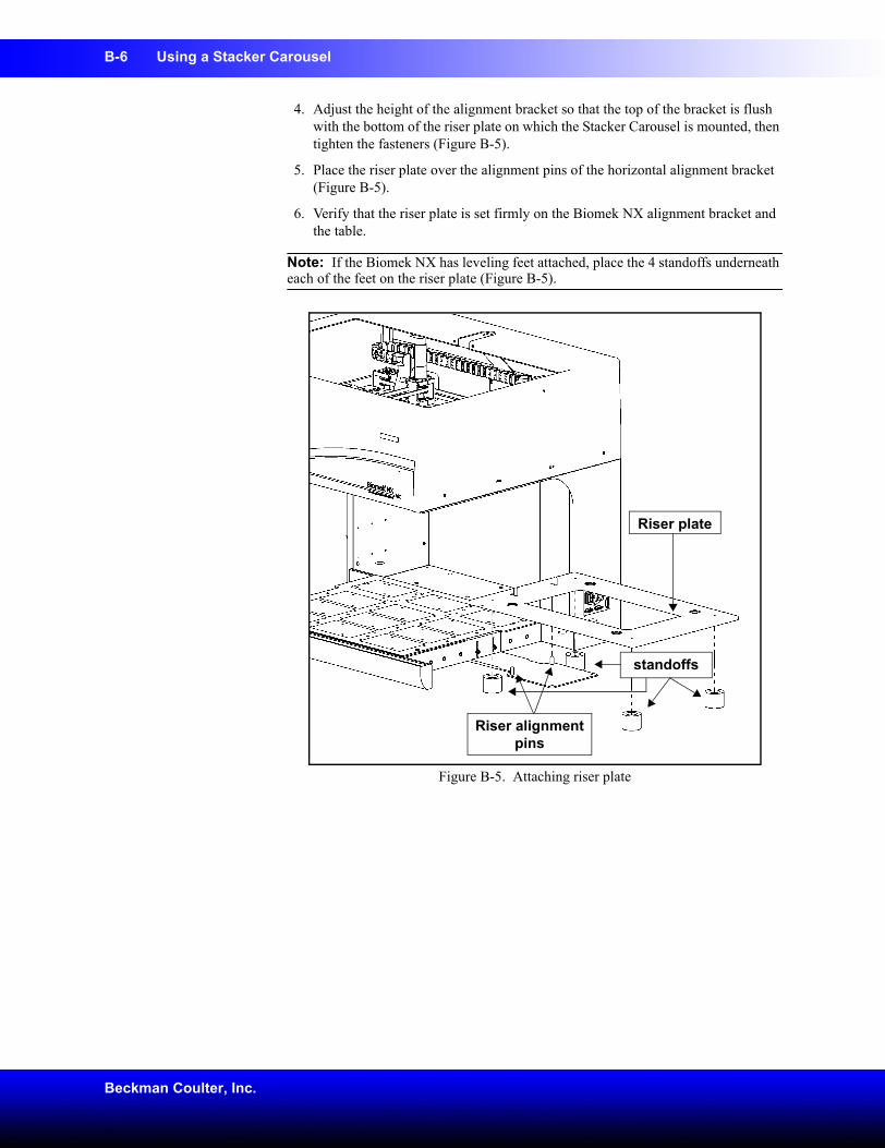
B-6 Using a Stacker Carousel
Beckman Coulter, Inc.
4. Adjust the height of the alignment bracket so that the top of the bracket is flush with the bottom of the riser plate on which the Stacker Carousel is mounted, then tighten the fasteners (Figure B-5).
5. Place the riser plate over the alignment pins of the horizontal alignment bracket (Figure B-5).
6. Verify that the riser plate is set firmly on the Biomek NX alignment bracket and the table.
Note: If the Biomek NX has leveling feet attached, place the 4 standoffs underneath each of the feet on the riser plate (Figure B-5).
Figure B-5. Attaching riser plate
Riser plate
Riser alignment pins
standoffs
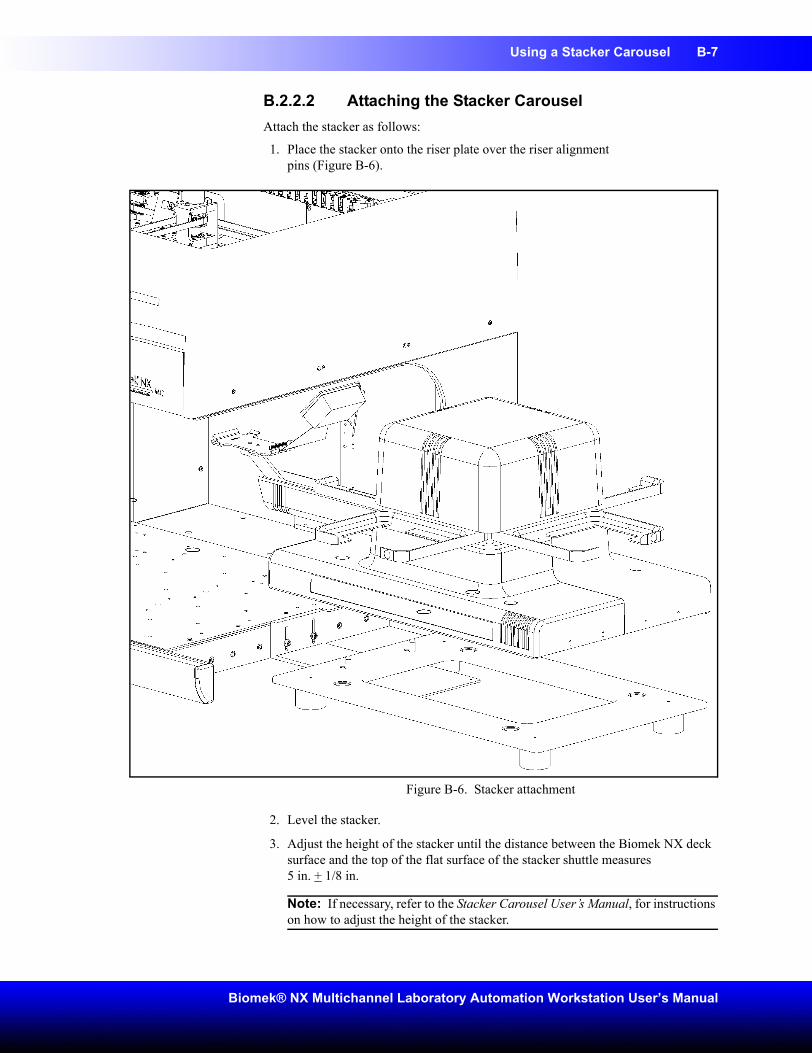
Using a Stacker Carousel B-7
Biomek® NX Multichannel Laboratory Automation Workstation User’s Manual
B.2.2.2 Attaching the Stacker CarouselAttach the stacker as follows:
1. Place the stacker onto the riser plate over the riser alignmentpins (Figure B-6).
Figure B-6. Stacker attachment
2. Level the stacker.
3. Adjust the height of the stacker until the distance between the Biomek NX deck surface and the top of the flat surface of the stacker shuttle measures5 in. + 1/8 in.
Note: If necessary, refer to the Stacker Carousel User’s Manual, for instructions on how to adjust the height of the stacker.
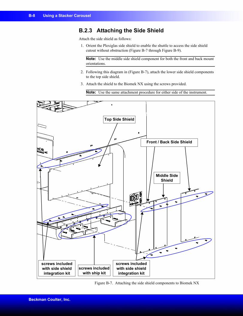
B-8 Using a Stacker Carousel
Beckman Coulter, Inc.
B.2.3 Attaching the Side ShieldAttach the side shield as follows:
1. Orient the Plexiglas side shield to enable the shuttle to access the side shield cutout without obstruction (Figure B-7 through Figure B-9).
Note: Use the middle side shield component for both the front and back mount orientations.
2. Following this diagram in (Figure B-7), attach the lower side shield components to the top side shield.
3. Attach the shield to the Biomek NX using the screws provided.
Note: Use the same attachment procedure for either side of the instrument.
Figure B-7. Attaching the side shield components to Biomek NX
screws included with side shield integration kit
Middle Side Shield
Front / Back Side Shield
Top Side Shield
screws included with ship kit
screws included with side shield integration kit
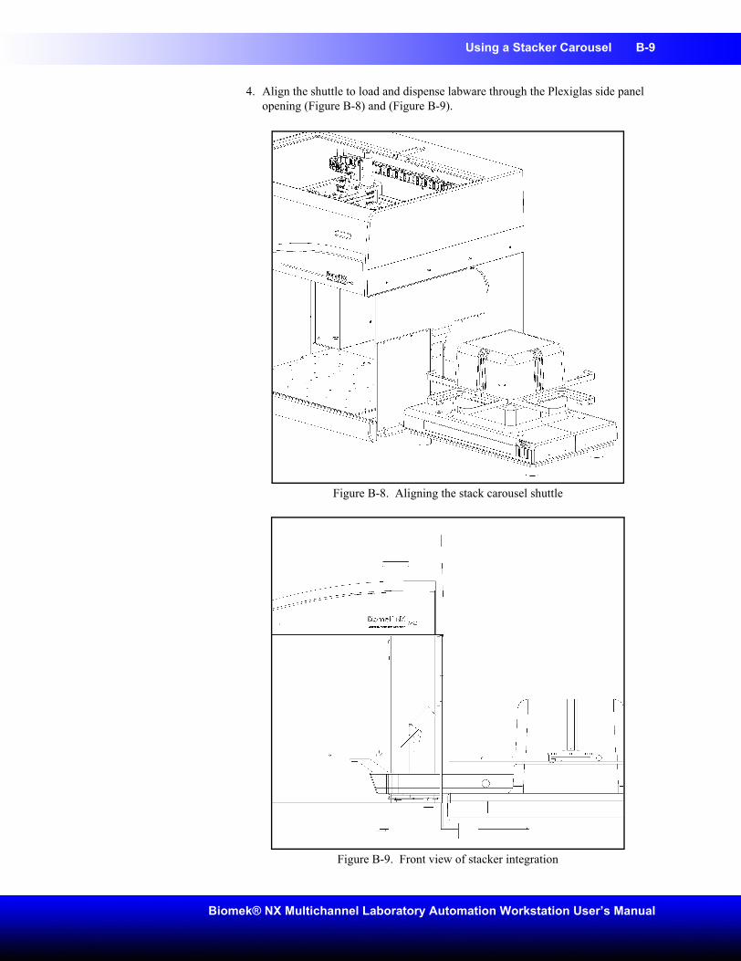
Using a Stacker Carousel B-9
Biomek® NX Multichannel Laboratory Automation Workstation User’s Manual
4. Align the shuttle to load and dispense labware through the Plexiglas side panel opening (Figure B-8) and (Figure B-9).
Figure B-8. Aligning the stack carousel shuttle
Figure B-9. Front view of stacker integration
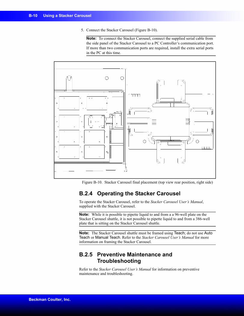
B-10 Using a Stacker Carousel
Beckman Coulter, Inc.
5. Connect the Stacker Carousel (Figure B-10).
Note: To connect the Stacker Carousel, connect the supplied serial cable from the side panel of the Stacker Carousel to a PC Controller’s communication port. If more than two communication ports are required, install the extra serial ports in the PC at this time.
Figure B-10. Stacker Carousel final placement (top view rear position, right side)
B.2.4 Operating the Stacker CarouselTo operate the Stacker Carousel, refer to the Stacker Carousel User’s Manual, supplied with the Stacker Carousel.
Note: While it is possible to pipette liquid to and from a a 96-well plate on the Stacker Carousel shuttle, it is not possible to pipette liquid to and from a 386-well plate that is sitting on the Stacker Carousel shuttle.
Note: The Stacker Carousel shuttle must be framed using Teach; do not use Auto Teach or Manual Teach. Refer to the Stacker Carousel User’s Manual for more information on framing the Stacker Carousel.
B.2.5 Preventive Maintenance and Troubleshooting
Refer to the Stacker Carousel User’s Manual for information on preventive maintenance and troubleshooting.
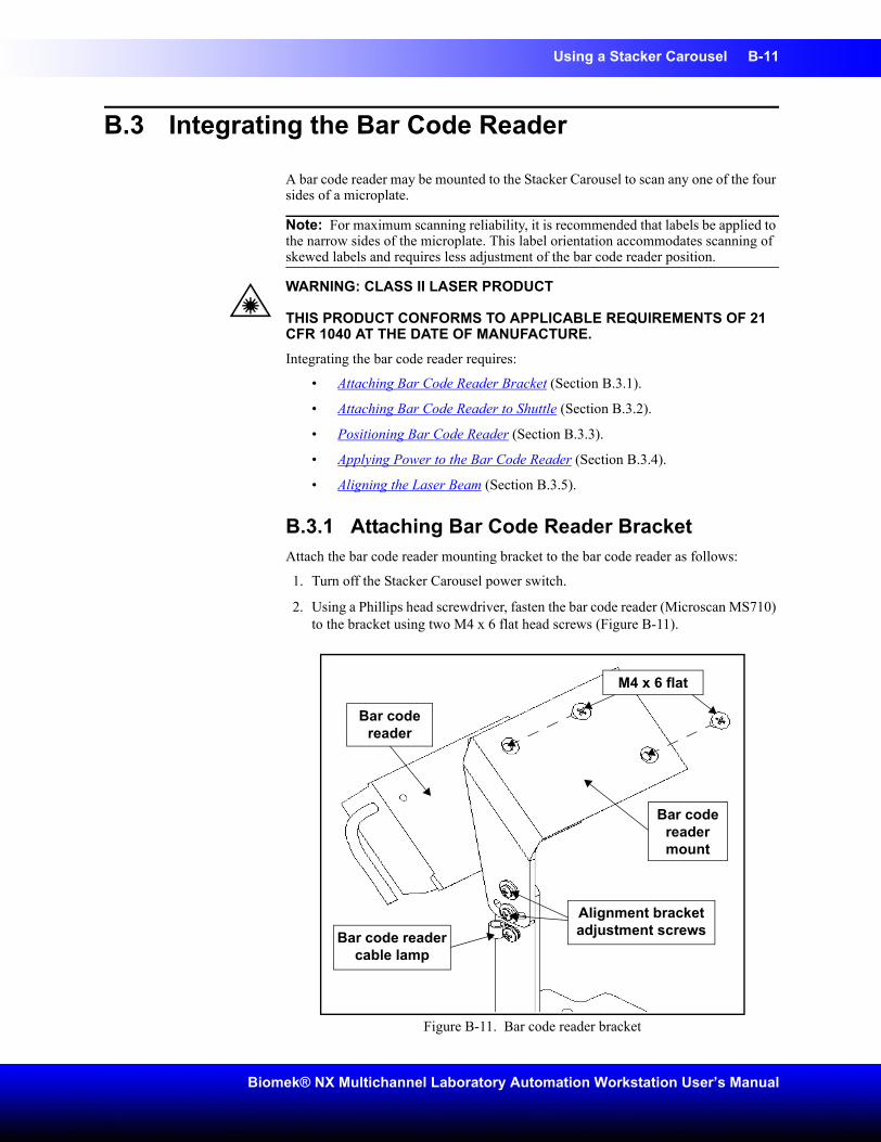
Using a Stacker Carousel B-11
Biomek® NX Multichannel Laboratory Automation Workstation User’s Manual
B.3 Integrating the Bar Code Reader
A bar code reader may be mounted to the Stacker Carousel to scan any one of the four sides of a microplate.
Note: For maximum scanning reliability, it is recommended that labels be applied to the narrow sides of the microplate. This label orientation accommodates scanning of skewed labels and requires less adjustment of the bar code reader position.
WARNING: CLASS II LASER PRODUCT
THIS PRODUCT CONFORMS TO APPLICABLE REQUIREMENTS OF 21 CFR 1040 AT THE DATE OF MANUFACTURE.Integrating the bar code reader requires:
• Attaching Bar Code Reader Bracket (Section B.3.1).
• Attaching Bar Code Reader to Shuttle (Section B.3.2).
• Positioning Bar Code Reader (Section B.3.3).
• Applying Power to the Bar Code Reader (Section B.3.4).
• Aligning the Laser Beam (Section B.3.5).
B.3.1 Attaching Bar Code Reader BracketAttach the bar code reader mounting bracket to the bar code reader as follows:
1. Turn off the Stacker Carousel power switch.
2. Using a Phillips head screwdriver, fasten the bar code reader (Microscan MS710) to the bracket using two M4 x 6 flat head screws (Figure B-11).
Figure B-11. Bar code reader bracket
Bar code reader mount
Bar code reader
Bar code reader cable lamp
Alignment bracket adjustment screws
M4 x 6 flat
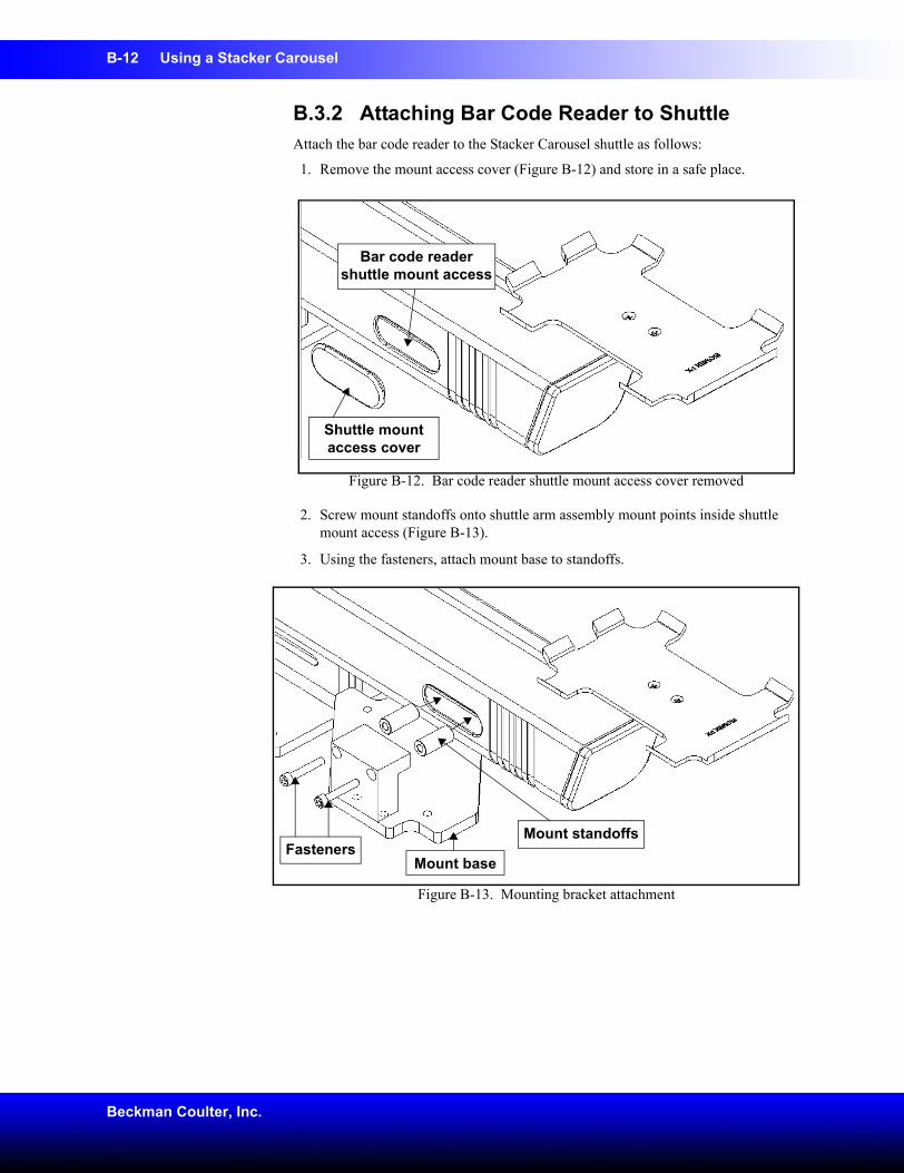
B-12 Using a Stacker Carousel
Beckman Coulter, Inc.
B.3.2 Attaching Bar Code Reader to ShuttleAttach the bar code reader to the Stacker Carousel shuttle as follows:
1. Remove the mount access cover (Figure B-12) and store in a safe place.
Figure B-12. Bar code reader shuttle mount access cover removed
2. Screw mount standoffs onto shuttle arm assembly mount points inside shuttle mount access (Figure B-13).
3. Using the fasteners, attach mount base to standoffs.
Figure B-13. Mounting bracket attachment
Shuttle mount access cover
Bar code reader shuttle mount access
FastenersMount base
Mount standoffs
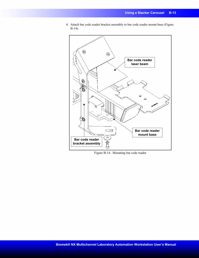
Using a Stacker Carousel B-13
Biomek® NX Multichannel Laboratory Automation Workstation User’s Manual
4. Attach bar code reader bracket assembly to bar code reader mount base (Figure B-14).
Figure B-14. Mounting bar code reader
Bar code reader bracket assembly
Bar code reader mount base
Bar code reader laser beam
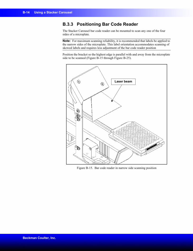
B-14 Using a Stacker Carousel
Beckman Coulter, Inc.
B.3.3 Positioning Bar Code ReaderThe Stacker Carousel bar code reader can be mounted to scan any one of the four sides of a microplate.
Note: For maximum scanning reliability, it is recommended that labels be applied to the narrow sides of the microplate. This label orientation accommodates scanning of skewed labels and requires less adjustment of the bar code reader position
Position the bracket so the highest edge is parallel with and away from the microplate side to be scanned (Figure B-15 through Figure B-25).
Figure B-15. Bar code reader in narrow side scanning position
Laser beam
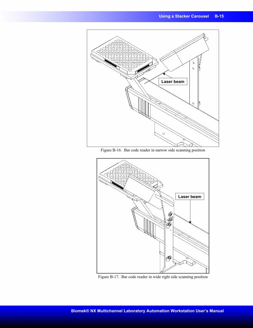
Using a Stacker Carousel B-15
Biomek® NX Multichannel Laboratory Automation Workstation User’s Manual
Figure B-16. Bar code reader in narrow side scanning position
Figure B-17. Bar code reader in wide right side scanning position
Laser beam
Laser beam
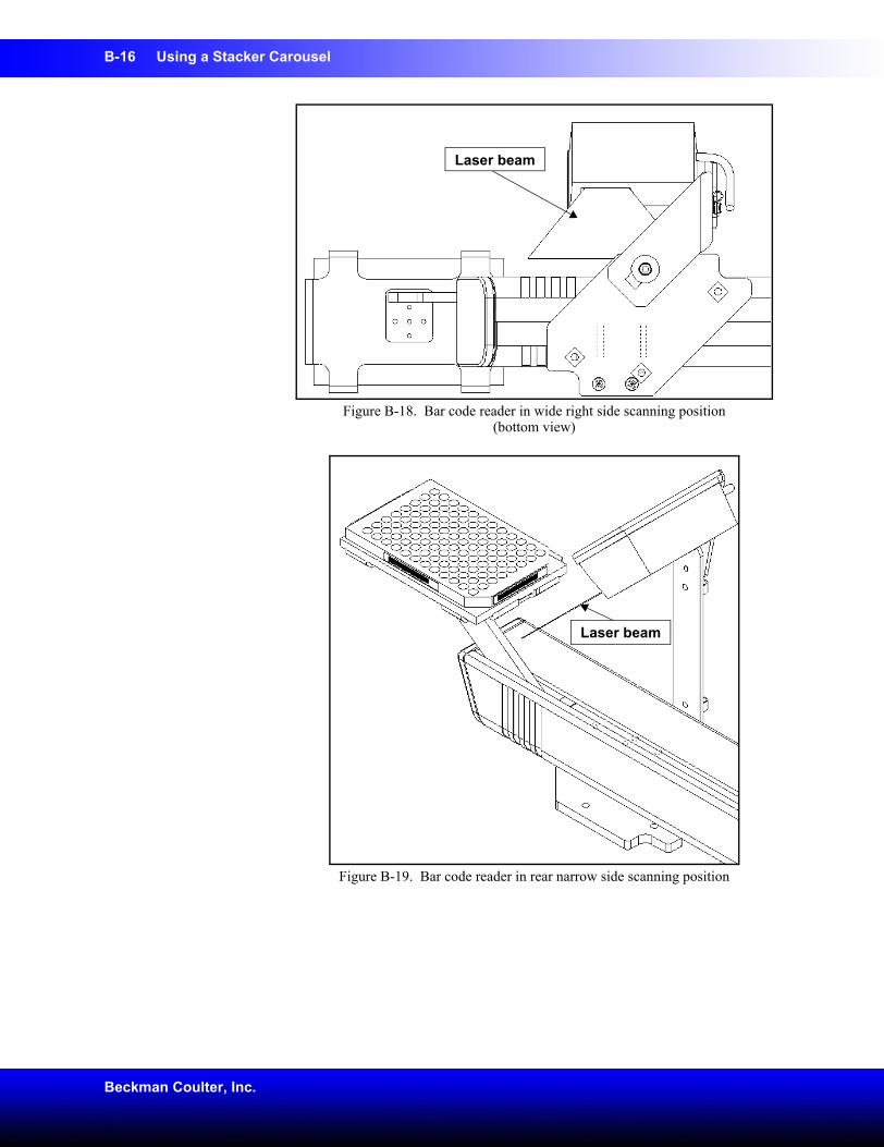
B-16 Using a Stacker Carousel
Beckman Coulter, Inc.
Figure B-18. Bar code reader in wide right side scanning position (bottom view)
Figure B-19. Bar code reader in rear narrow side scanning position
Laser beam
Laser beam
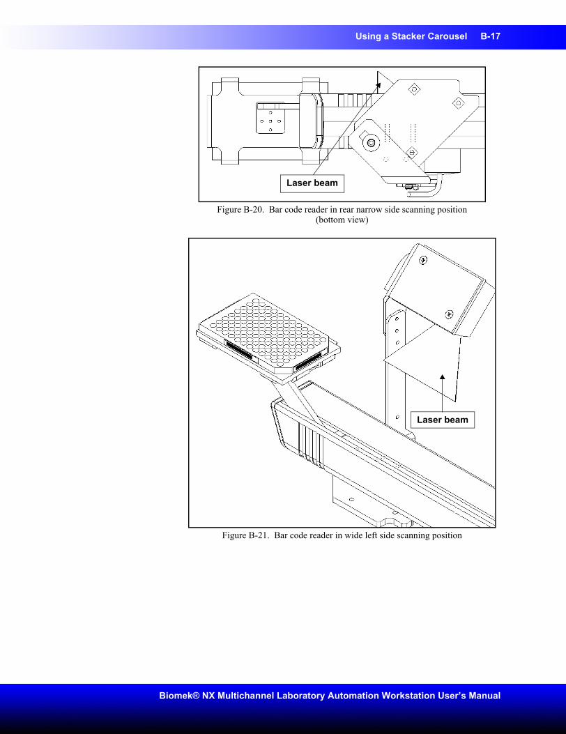
Using a Stacker Carousel B-17
Biomek® NX Multichannel Laboratory Automation Workstation User’s Manual
Figure B-20. Bar code reader in rear narrow side scanning position (bottom view)
Figure B-21. Bar code reader in wide left side scanning position
Laser beam
Laser beam
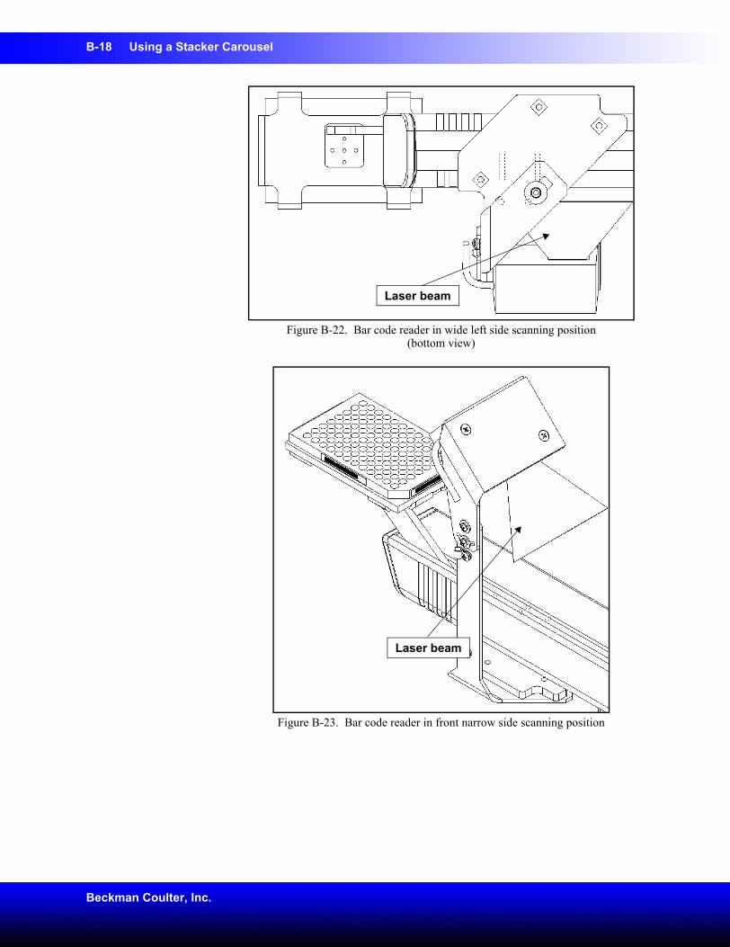
B-18 Using a Stacker Carousel
Beckman Coulter, Inc.
Figure B-22. Bar code reader in wide left side scanning position (bottom view)
Figure B-23. Bar code reader in front narrow side scanning position
Laser beam
Laser beam
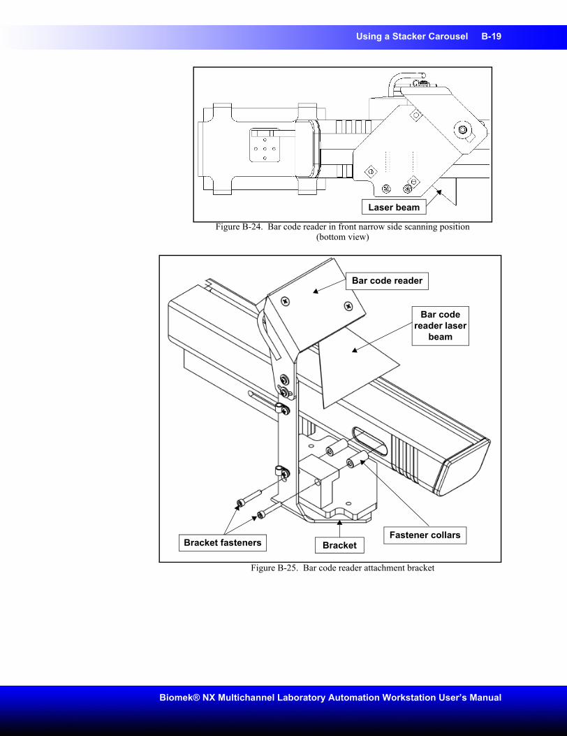
Using a Stacker Carousel B-19
Biomek® NX Multichannel Laboratory Automation Workstation User’s Manual
Figure B-24. Bar code reader in front narrow side scanning position (bottom view)
Figure B-25. Bar code reader attachment bracket
Laser beam
Bar code reader laser
beam
Bar code reader
Fastener collarsBracketBracket fasteners
B-20 Using a Stacker Carousel
Beckman Coulter, Inc.
B.3.4 Applying Power to the Bar Code ReaderCAUTION: To avoid serious damage to the instrument, make sure that the laboratory site voltage/frequency matches the voltage/frequency that was ordered for the instrument.WARNING: Do not attempt to remove or replace covers while the unit is powered on. Disconnect power before removing or replacing a cover.Apply power to the bar code reader as follows:
1. Secure the MS710 power cable to the rear panel of the Stacker Carousel.
Note: Make sure the cable is connected to the port marked BCR and the cable routing does not interfere with the operation of the Stacker Carousel.
2. Turn on the Stacker Carousel power switch.
B.3.5 Aligning the Laser BeamWARNING: Avoid direct exposure to the laser beam. Never look directly into the laser beam, and never leave the laser on, open, or unattended.
WARNING: Always have the laser module access cover, located on the bar code reader, in place when operating or troubleshooting the laser module.To align the laser beam correctly:
1. Verify that the red laser beam is scanning down across the path of the shuttle. If the laser beam is not directed downward toward the shuttle, turn off the Stacker Carousel power switch.
2. Review Section B.3.3, Positioning Bar Code Reader, before correcting the orientation of the MS710.
3. Visually check to make sure the red laser beam is scanning down across the path of the shuttle. If the laser beam is not directed downward toward the shuttle, turn off the Stacker Carousel power switch, and complete step 2 again. If the laser beam is scanning down across the path of the shuttle, continue to step 4.
4. Make sure the laser scans down through the appropriate tunnel opening. For reading labels on the narrow side of the microplate, the laser should scan down through one of two slots in the top of the shuttle tunnel. For reading labels on the wide side of the microplate, the laser should scan down through one of the two slots in the side of the shuttle tunnel.
5. If the position of the MS710 needs to be adjusted; loosen the screw/washer assemblies that attach the bar code reader bracket (Figure B-25) to the shuttle tunnel, adjust the tilt of the bar code reader until it is aimed properly, then tighten the screw/washer assemblies.
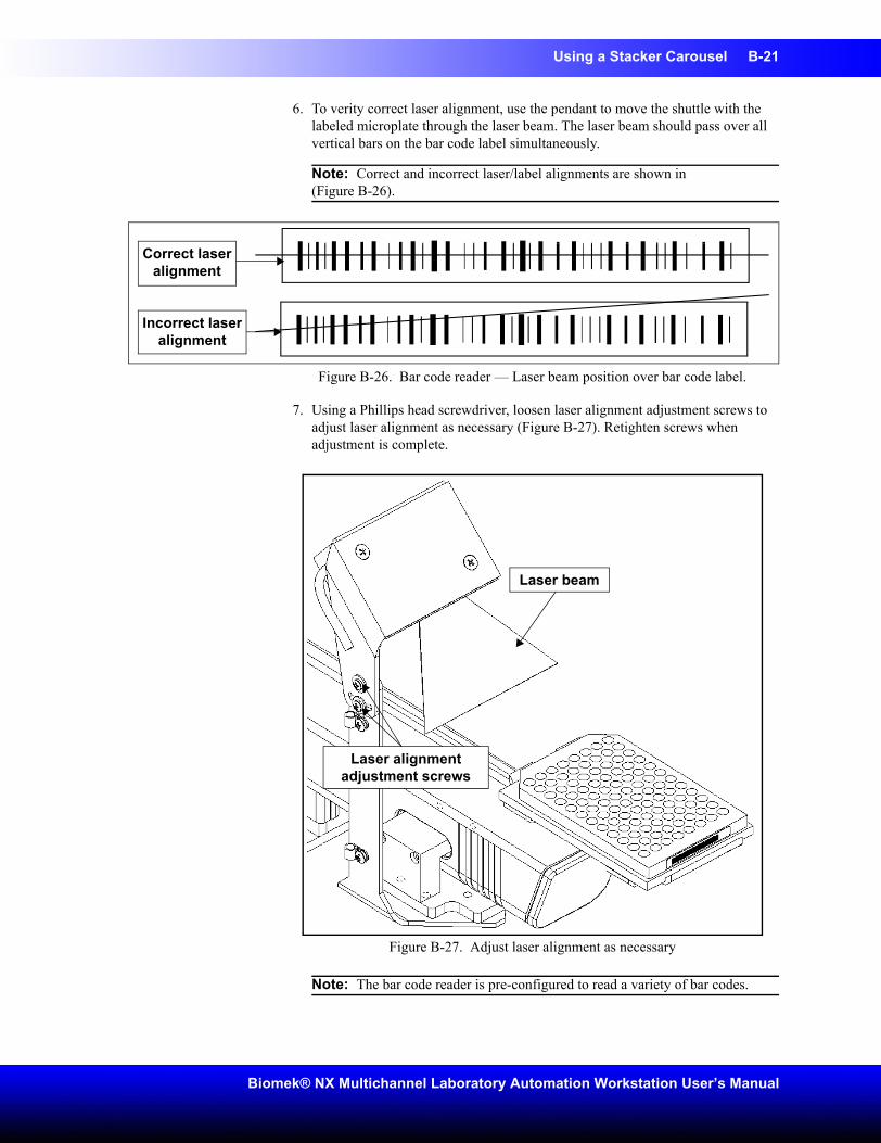
Using a Stacker Carousel B-21
Biomek® NX Multichannel Laboratory Automation Workstation User’s Manual
6. To verity correct laser alignment, use the pendant to move the shuttle with the labeled microplate through the laser beam. The laser beam should pass over all vertical bars on the bar code label simultaneously.
Note: Correct and incorrect laser/label alignments are shown in(Figure B-26).
Figure B-26. Bar code reader — Laser beam position over bar code label.
7. Using a Phillips head screwdriver, loosen laser alignment adjustment screws to adjust laser alignment as necessary (Figure B-27). Retighten screws when adjustment is complete.
Figure B-27. Adjust laser alignment as necessary
Note: The bar code reader is pre-configured to read a variety of bar codes.
Correct laser alignment
Incorrect laser alignment
Laser alignment adjustment screws
Laser beam
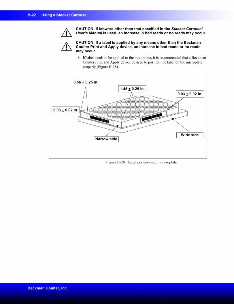
B-22 Using a Stacker Carousel
Beckman Coulter, Inc.
CAUTION: If labware other than that specified in the Stacker Carousel User’s Manual is used, an increase in bad reads or no reads may occur.
CAUTION: If a label is applied by any means other than the Beckman Coulter Print and Apply device, an increase in bad reads or no reads may occur.8. If label needs to be applied to the microplate, it is recommended that a Beckman
Coulter Print and Apply device be used to position the label on the microplate properly (Figure B-28).
Figure B-28. Label positioning on microplate
0.03 + 0.02 in.1.45 + 0.25 in.
Narrow sideWide side
0.56 + 0.25 in.
0.03 + 0.02 in.
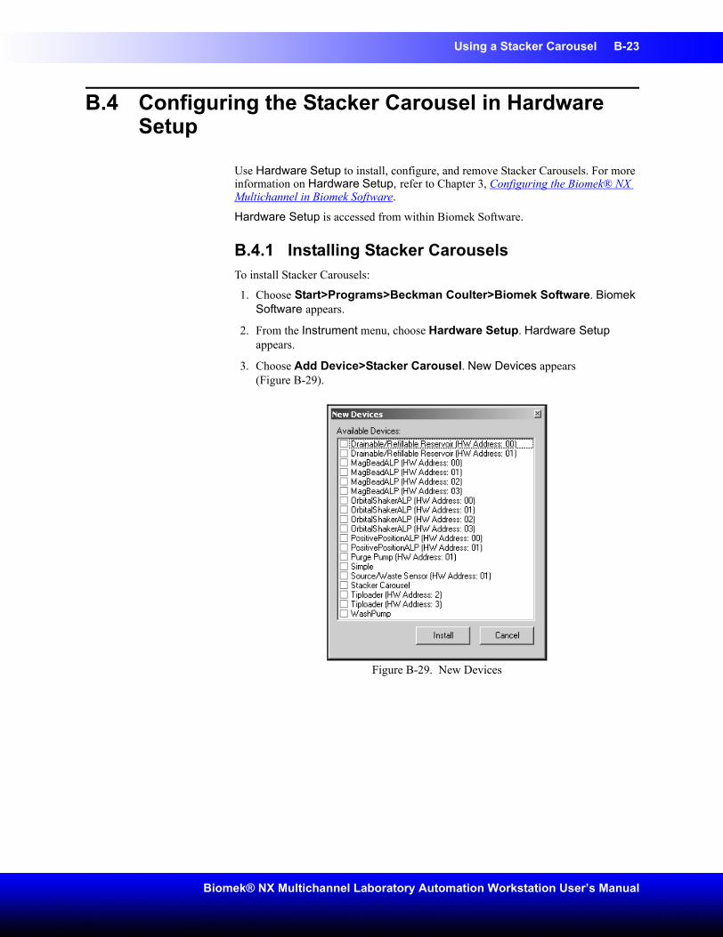
Using a Stacker Carousel B-23
Biomek® NX Multichannel Laboratory Automation Workstation User’s Manual
B.4 Configuring the Stacker Carousel in Hardware Setup
Use Hardware Setup to install, configure, and remove Stacker Carousels. For more information on Hardware Setup, refer to Chapter 3, Configuring the Biomek® NX Multichannel in Biomek Software.
Hardware Setup is accessed from within Biomek Software.
B.4.1 Installing Stacker CarouselsTo install Stacker Carousels:
1. Choose Start>Programs>Beckman Coulter>Biomek Software. Biomek Software appears.
2. From the Instrument menu, choose Hardware Setup. Hardware Setup appears.
3. Choose Add Device>Stacker Carousel. New Devices appears(Figure B-29).
Figure B-29. New Devices
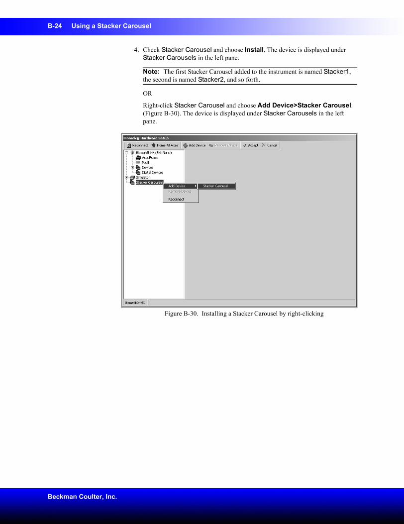
B-24 Using a Stacker Carousel
Beckman Coulter, Inc.
4. Check Stacker Carousel and choose Install. The device is displayed under Stacker Carousels in the left pane.
Note: The first Stacker Carousel added to the instrument is named Stacker1, the second is named Stacker2, and so forth.
OR
Right-click Stacker Carousel and choose Add Device>Stacker Carousel. (Figure B-30). The device is displayed under Stacker Carousels in the left pane.
Figure B-30. Installing a Stacker Carousel by right-clicking
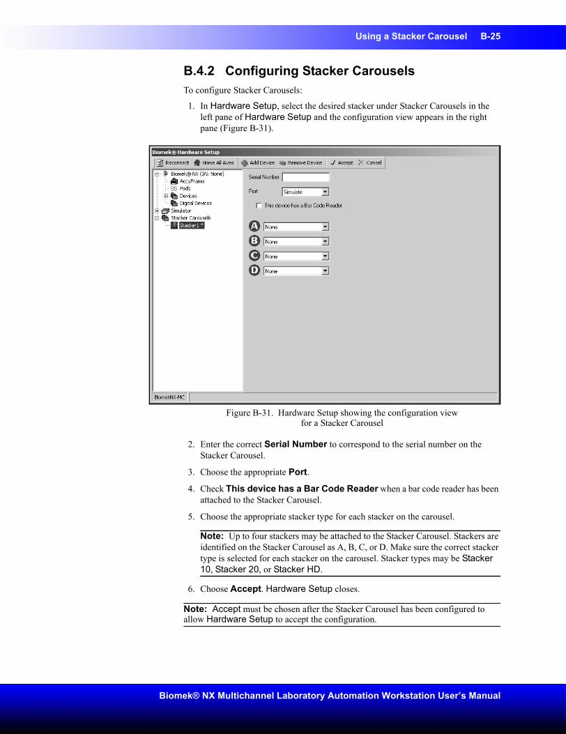
Using a Stacker Carousel B-25
Biomek® NX Multichannel Laboratory Automation Workstation User’s Manual
B.4.2 Configuring Stacker CarouselsTo configure Stacker Carousels:
1. In Hardware Setup, select the desired stacker under Stacker Carousels in the left pane of Hardware Setup and the configuration view appears in the right pane (Figure B-31).
Figure B-31. Hardware Setup showing the configuration view for a Stacker Carousel
2. Enter the correct Serial Number to correspond to the serial number on the Stacker Carousel.
3. Choose the appropriate Port.
4. Check This device has a Bar Code Reader when a bar code reader has been attached to the Stacker Carousel.
5. Choose the appropriate stacker type for each stacker on the carousel.
Note: Up to four stackers may be attached to the Stacker Carousel. Stackers are identified on the Stacker Carousel as A, B, C, or D. Make sure the correct stacker type is selected for each stacker on the carousel. Stacker types may be Stacker 10, Stacker 20, or Stacker HD.
6. Choose Accept. Hardware Setup closes.
Note: Accept must be chosen after the Stacker Carousel has been configured to allow Hardware Setup to accept the configuration.
B-26 Using a Stacker Carousel
Beckman Coulter, Inc.
B.4.3 Removing Stacker CarouselsTo remove Stacker Carousels:
1. In Hardware Setup, right-click the desired device under Stacker Carousels.
2. Choose Remove Device. The device is removed from the installed stackers under Stacker Carousels in the left pane.
OR
1. Select the desired stacker under Stacker Carousel.
2. Choose Remove Device from the top of Hardware Setup. The device is removed the installed devices under Stacker Carousels in the left pane.
Using a Stacker Carousel B-27
Biomek® NX Multichannel Laboratory Automation Workstation User’s Manual
B.5 Framing the Stacker Carousel
The Stacker Carousel is framed using the AccuFrame and the Framing Tool Adaptor.
To frame the Stacker Carousel:
1. Using the Control Pendant, choose SHUTTLE IN and SHUTTLE OUT to ensure the shuttle of the Stacker Carousel is in the correct position for framing. The shuttle should be out for framing.
Note: Refer to the Stacker Carousel User’s Manual (Beckman Part Number 148598) for more information on using the Control Pendant.
CAUTION: To prevent damage to the shuttle, first place the AccuFrame into the Framing Tool Adaptor. Then place the AccuFrame with the attached adaptor on the shuttle.2. Manually place the AccuFrame into the Framing Tool Adaptor by placing the
front right corner first and pushing the AccuFrame gently down into the adaptor (Figure B-32).
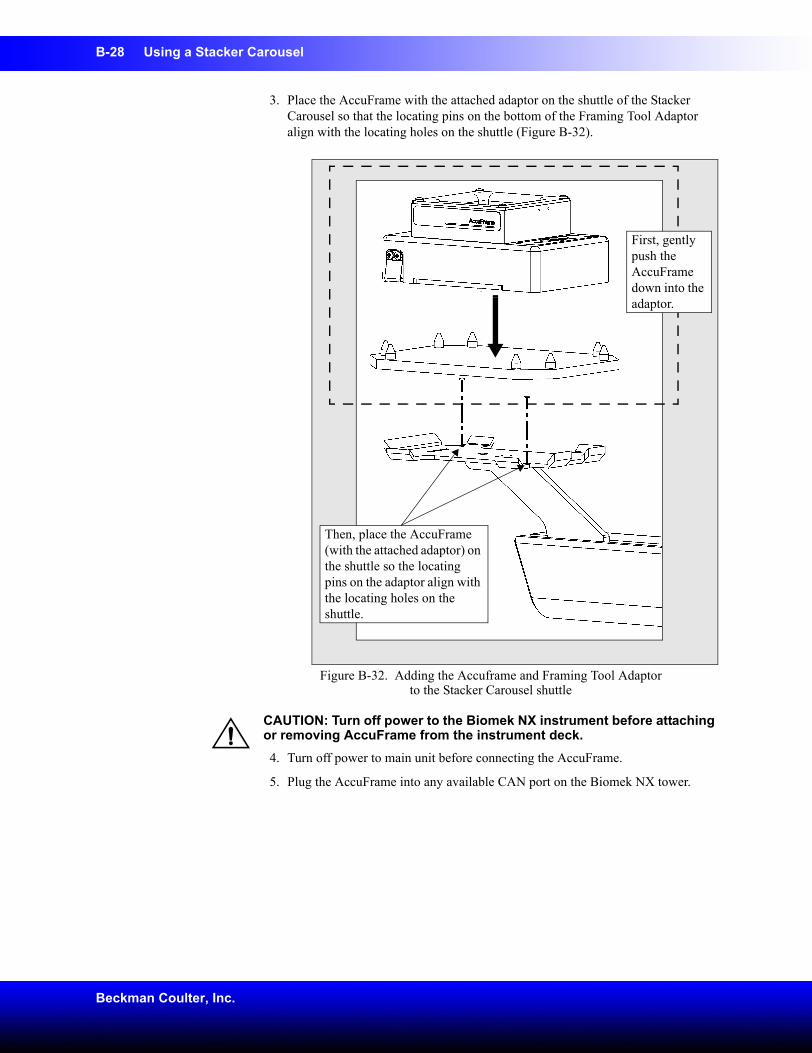
B-28 Using a Stacker Carousel
Beckman Coulter, Inc.
3. Place the AccuFrame with the attached adaptor on the shuttle of the Stacker Carousel so that the locating pins on the bottom of the Framing Tool Adaptor align with the locating holes on the shuttle (Figure B-32).
Figure B-32. Adding the Accuframe and Framing Tool Adaptor to the Stacker Carousel shuttle
CAUTION: Turn off power to the Biomek NX instrument before attaching or removing AccuFrame from the instrument deck.4. Turn off power to main unit before connecting the AccuFrame.
5. Plug the AccuFrame into any available CAN port on the Biomek NX tower.
First, gently push the AccuFrame down into the adaptor.
Then, place the AccuFrame (with the attached adaptor) on the shuttle so the locating pins on the adaptor align with the locating holes on the shuttle.
Using a Stacker Carousel B-29
Biomek® NX Multichannel Laboratory Automation Workstation User’s Manual
WARNING: Make sure the light curtain is not violated by the AccuFrame cable. If the light curtain is violated, the framing process halts immediately.WARNING: Make sure the AccuFrame cable does not interfere with pod movement.6. Turn on power to main unit.
7. Frame the Stacker Carousel according to procedures outlined in Chapter 4, Framing Instructions.
Note: The Stacker Carousel shuttle must be framed using Teach; do not use Auto Teach or Manual Teach.

xxiii
Biomek® NX Multichannel Laboratory Automation Workstation User’s Manual
Index
Numerics384-Channel 30µL Head
description 2-596-Channel 200µL Head
description 2-5
AAbsolute Move
using in Advanced Manual Control 5-10AccuFrame
calibrated by Beckman Coulter Service Engineer 4-2
defined 4-2installing the 4-6troubleshooting 4-26using the 4-6
Advanced Manual Controlaccessing 5-4defined 5-1selection areas for Multichannel Pod 5-6
ALPsoverview 1-6
BBar Code Reader
aligning laser beam B-20applying power to B-20attachment bracket B-19integrating with Stacker Carousel B-11positioning labels on microplates B-22positioning on Stacker Carousel B-14
Biomek NXdescribed 1-1main components
ALPs 1-6deck 1-5Device Controller 1-6light curtain 1-8protective side safety shields 1-8
Ccontrol modes
for the Multichannel Pod 2-4overview 1-1
Ddeck
overview 1-5Delta
defined 5-5setting values for the Multichannel Pod 5-8
delta valuesusing in Manual Teach 4-17
Device Controlleroverview 1-6
devicesoptional
overview 1-6
Ffirmware version
viewing 5-4
xxiv Index
Beckman Coulter, Inc.
framingusing delta value 4-17using graphic alignment tool 4-15
framing (teaching)grippers 4-21instructions 4-1Stacker Carousel B-27using Manual Teach 4-11
framing fixtureattaching to Multichannel Head 4-5
fuseschanging in tower 1-11
Ggraphic alignment tool
using during framing 4-15grippers
defined 2-14extending and retracting 5-11framing 2-13framing (teaching) 4-21removing 2-17testing framing accuracy 4-25troubleshooting 2-15
HHardware Setup
accessing 3-2choosing Frame Gripper 4-22configuring a Multichannel Pod in 3-5configuring a new head in 3-5configuring the Biomek NX in 3-4defined 3-1Multichannel Pod properties in 3-7saving, restoring, and deleting
settings in 3-10understanding the options in 3-3using Accept in 3-3
headschanging 2-5installing 2-9removing 2-7
homingall axes of a pod 5-3pod 4-4
Iindicator lights
defined 1-5
Llight curtain
maintenance 1-9status indicator lights 1-5
MManual Control
accessing 5-2defined 5-1dialog display 5-1, 5-2using 5-2
Manual Teachdelta value 4-17directional buttons 4-17framing Z-axis 4-19using 4-11using delta values 4-17using graphic alignment tool 4-15
Move Z-Maxusing in Advanced Manual Control
for a Multichannel Pod 5-7movement vectors
understanding for a Multichannel Pod 5-9Multichannel Pod
control modes 2-4current coordinates displayed 5-7defined 2-1immediate moves for 5-5main components 2-3
head 2-3movements 2-4moving to a safe roving height 5-7performing absolute moves for 5-10performing relative moves 5-7wrist ground strap
changing heads 2-6
Oopen architecture
instrument design concept 1-1optional devices
defined B-1
Index xxv
Biomek® NX Multichannel Laboratory Automation Workstation User’s Manual
Ppod
framing (teaching)Multichannel 4-3Span-8 4-3
manually controlling 5-3moving to a specific deck position 5-4Multichannel
defined 2-1, 3-5stopping in Manual Control 5-4teaching (framing)
Multichannel 4-3Span-8 4-3
Pod Editorproperties defined 3-7
Ssettings
saving, restoring, and deleting in Hardware Setup 3-10
Span-8 Podmovement values defined 5-9
specificationsBiomek NX system A-1
Stacker Carousel, Biomek FXattaching alignment bracket B-5
attaching side shields B-7attaching stacker B-7framing B-27integrating B-1mounting B-5operating B-10positioning the B-3
Tteaching (framing)
grippers 4-21instructions 4-1Stacker Carousel B-27using Manual Teach 4-11
towerchanging fuses in 1-11troubleshooting 1-10
VVector Builder
defined 5-5using 5-9
Wwrist ground strap
changing heads 2-6
