biomek nx multichannel laboratory automation workstation ... nx multichannel quick-start...biomek®...
TRANSCRIPT
Beckman Coulter, Inc4300 N. Harbor Boulevard, Fullerton, CA 92834-3100
Copyright © 2004 Beckman Coulter, Inc. Printed in U.S.A.
Biomek® NX Multichannel Laboratory Automation
WorkstationQuick-Start Guide
Beckman Coulter PN 987893Revision AB
September 2004
1-ii
Beckman Coulter, Inc.
Except as provided in writing signed by an officer to Beckman Coulter, Inc., this system and any related documentation are provided “as is” without warranty of any kind, expressed or implied, including that the system is “error free.” This information is presented in good faith, but Beckman Coulter, Inc. does not warrant, guarantee, or make any representations regarding the use or the results of the use of this system and related documentation in terms of correctness, accuracy, reliability, currentness, omissions, or otherwise. The entire risk as to the use, results, and performance of this system and related documentation is assumed by the user.
Except as expressly provided herein, Beckman Coulter, Inc. makes no other warranty, whether oral or written, expressed or implied, as to any matter whatsoever, including but not limited to those concerning merchantability and fitness for a particular purpose, nor is freedom from any patent owned by Beckman Coulter, Inc. or by others to be inferred.
LIMITATIONS OF LIABILITYBeckman Coulter, Inc. shall not be liable, to any extent whatsoever, for any damages resulting from or arising out of the use or performance of this system and related documentation or the procedures specified in this manual, regardless of foreseeability or the form of action, whether in contract, tort (including negligence), breach of warranty, strict liability or otherwise, and including but not limited to damages resulting from loss of data, loss of anticipated profits, or any special, indirect, incidental or consequential damages. In no event shall Beckman Coulter, Inc.’s liability to the user exceed the amount paid by the user to Beckman Coulter, Inc. hereunder. The user assumes full responsibility for the results obtained from the use of this system and related documentation and for application of such results.
Beckman Coulter, SAGIAN OperationsIndianapolis, Indianawww.beckmancoulter.com
Biomek, Beckman Coulter, and the Beckman Coulter logo are registered trademarks of Beckman Coulter, Inc.Microsoft and MS-DOS are registered trademarks and Windows is a trademark of Microsoft Corporation. All other trademarks appearing in this manual are owned by their respective companies.
Copyright 2004 by Beckman Coulter, Inc. All rights reserved. No part of this publication may be reproduced, distributed, or transmitted in any form or by any means, electronic, mechanical, photocopying, recording, or otherwise, or stored in a database or retrieval system, without the prior written permission of Beckman Coulter, Inc.
1-iii
Biomek® NX Multichannel Laboratory Automation Workstation Quick-Start Guide
Warranty and Returned Goods RequirementsAll standard Beckman Coulter, Inc. policies governing returned goods apply to this product. Subject to the exceptions and upon the conditions stated below, the Company warrants that the products sold under this sales agreement shall be free from defects in workmanship and materials for one year after delivery of the products to the original Purchaser by the Company, and if any such product should prove to be defective within such one year period, the Company agrees, at its option, either (1) to correct by repair or at the Company’s election by replacement, any such defective product provided that investigation and factory inspection discloses that such defect developed under normal and proper use, or (2) to refund the purchase price. The exceptions and conditions mentioned above are as follows:
a. Components or accessories manufactured by the Company which by their nature are not intended to and will not function for one year are warranted only to reasonable service for a reasonable time. What constitutes a reasonable time and a reasonable service shall be determined solely by the Company. A complete list of such components and accessories is maintained at the factory.
b. The Company makes no warranty with respect to components or accessories not manufactured by it. In the event of defect in any such component or accessory, the Company will give reasonable assistance to Purchaser in obtaining from the manufacturer’s own warranty.
c. Any product claimed to be defective must, if required by the Company, be returned to the factory, transportation charges prepaid, and will be returned to Purchaser with transportation charges collect unless the product is found to be defective, in which case the product must be properly decontaminated of any chemical, biological, or radioactive hazardous material.
d. The Company shall be released from all obligations under all warranties, either expressed or implied, if any product covered hereby is repaired or modified by persons other than its own authorized service personnel, unless such repair by others is made with the written consent of the Company.
e. If the product is a reagent or the like, it is warranted only to conform to the quantity and content and for the period (but not in excess of one year) stated on the label at the time of delivery.
It is expressly agreed that the above warranty shall be in lieu of all warranties of fitness and of the warranty of merchantability, and that the company shall have no liability for special or consequential damages of any kind or from any cause whatsoever arising out of the manufacture, use, sale, handling, repair, maintenance, or replacement of any of the products sold under the sales agreement.
Representatives and warranties made by any person, including dealers and representatives of the Company, which are consistent or in conflict with the terms of this warranty, shall not be binding upon the Company unless reduced in writing and approved by an expressly authorized officer of the Company.
Parts replaced during the warranty period are warranted to the end of the instrument warranty.
Note: Performance characteristics and specifications are only warranted when Beckman Coulter replacement parts are used.

v
Biomek® NX Multichannel Laboratory Automation Workstation Quick-Start Guide
Table of Contents
Warranty and Returned Goods Requirements . . . . . . . . . . . . . . . . . . . . . . . . . . . . . . . . . . . iii
Table of Contents . . . . . . . . . . . . . . . . . . . . . . . . . . . . . . . . . . . . . . . . . . . v
1 Introducing the Biomek® NX Laboratory Automation Workstation1.1 Introduction . . . . . . . . . . . . . . . . . . . . . . . . . . . . . . . . . . . . . . . . . . . . . . . . . . . . . . 1-1
1.1.1 How to Use This Quick-Start Guide. . . . . . . . . . . . . . . . . . . . . . . . . . . . 1-21.2 Biomek® NX. . . . . . . . . . . . . . . . . . . . . . . . . . . . . . . . . . . . . . . . . . . . . . . . . . . . . 1-3
1.2.1 Automated Labware Positioners (ALPs) . . . . . . . . . . . . . . . . . . . . . . . . 1-41.2.2 Light Curtain and Other Protective Barriers. . . . . . . . . . . . . . . . . . . . . . 1-5
1.3 Biomek Software . . . . . . . . . . . . . . . . . . . . . . . . . . . . . . . . . . . . . . . . . . . . . . . . . . 1-61.4 Starting the Biomek® NX . . . . . . . . . . . . . . . . . . . . . . . . . . . . . . . . . . . . . . . . . . . 1-7
1.4.1 Turning On the Biomek NX . . . . . . . . . . . . . . . . . . . . . . . . . . . . . . . . . . 1-71.4.2 Launching the Software . . . . . . . . . . . . . . . . . . . . . . . . . . . . . . . . . . . . . 1-71.4.3 Homing All Axes of the Biomek NX Pod . . . . . . . . . . . . . . . . . . . . . . . 1-8
2 Learning to Create Methods for the Biomek® NX2.1 Overview . . . . . . . . . . . . . . . . . . . . . . . . . . . . . . . . . . . . . . . . . . . . . . . . . . . . . . . . 2-12.2 Creating a New Method. . . . . . . . . . . . . . . . . . . . . . . . . . . . . . . . . . . . . . . . . . . . . 2-22.3 Configuring the Instrument Setup Step . . . . . . . . . . . . . . . . . . . . . . . . . . . . . . . . . 2-42.4 Configuring a Transfer Step . . . . . . . . . . . . . . . . . . . . . . . . . . . . . . . . . . . . . . . . . 2-8
2.4.1 Inserting a Transfer Step. . . . . . . . . . . . . . . . . . . . . . . . . . . . . . . . . . . . . 2-82.4.2 Configuring Tip Handling . . . . . . . . . . . . . . . . . . . . . . . . . . . . . . . . . . . 2-92.4.3 Configuring Source Labware . . . . . . . . . . . . . . . . . . . . . . . . . . . . . . . . 2-102.4.4 Configuring Destination Labware . . . . . . . . . . . . . . . . . . . . . . . . . . . . 2-11
2.5 Configuring a Move Labware Step . . . . . . . . . . . . . . . . . . . . . . . . . . . . . . . . . . . 2-132.6 Using the Finish Step. . . . . . . . . . . . . . . . . . . . . . . . . . . . . . . . . . . . . . . . . . . . . . 2-14
2.6.1 Handling Configuration Errors . . . . . . . . . . . . . . . . . . . . . . . . . . . . . . . 2-142.7 Saving a Method . . . . . . . . . . . . . . . . . . . . . . . . . . . . . . . . . . . . . . . . . . . . . . . . . 2-152.8 Running a Method . . . . . . . . . . . . . . . . . . . . . . . . . . . . . . . . . . . . . . . . . . . . . . . . 2-16
vi
Beckman Coulter, Inc.
3 Using the Editors While Creating Methods3.1 Overview . . . . . . . . . . . . . . . . . . . . . . . . . . . . . . . . . . . . . . . . . . . . . . . . . . . . . . . . 3-13.2 General Description of Editors . . . . . . . . . . . . . . . . . . . . . . . . . . . . . . . . . . . . . . . 3-2
3.2.1 Project Menu. . . . . . . . . . . . . . . . . . . . . . . . . . . . . . . . . . . . . . . . . . . . . . 3-33.2.2 Instrument Menu. . . . . . . . . . . . . . . . . . . . . . . . . . . . . . . . . . . . . . . . . . . 3-3
3.3 Creating New Labware in the Labware Type Editor . . . . . . . . . . . . . . . . . . . . . . . 3-53.4 Checking In a Method and Project File . . . . . . . . . . . . . . . . . . . . . . . . . . . . . . . . . 3-83.5 Creating a New Deck. . . . . . . . . . . . . . . . . . . . . . . . . . . . . . . . . . . . . . . . . . . . . . . 3-93.6 Manually Controlling the Pod . . . . . . . . . . . . . . . . . . . . . . . . . . . . . . . . . . . . . . . 3-113.7 Quick-Start Guide Summary . . . . . . . . . . . . . . . . . . . . . . . . . . . . . . . . . . . . . . . . 3-13
1-1
Biomek® NX Multichannel Laboratory Automation Workstation Quick-Start Guide
1 Introducing the Biomek® NX Laboratory Automation Workstation
1.1 IntroductionWelcome to the Biomek® NX Laboratory Automation Workstation.
This quick-start guide is designed to introduce you to the Biomek NX Multichannel instrument and Biomek Software operating system. This quick-start guide includes:
• Getting to Know the Biomek® NX Laboratory Automation Workstation (this chapter) — an overview of the hardware and operating software.
• Learning to Create Methods for the Biomek® NX (Chapter 2) — an overview of how to create methods using the Biomek Software.
• Using the Editors While Creating Methods (Chapter 3) — an overview of how to use the editors in Biomek Software to accommodate unique method requirements.
1-2 Introducing the Biomek® NX Laboratory Automation Workstation
Beckman Coulter, Inc.
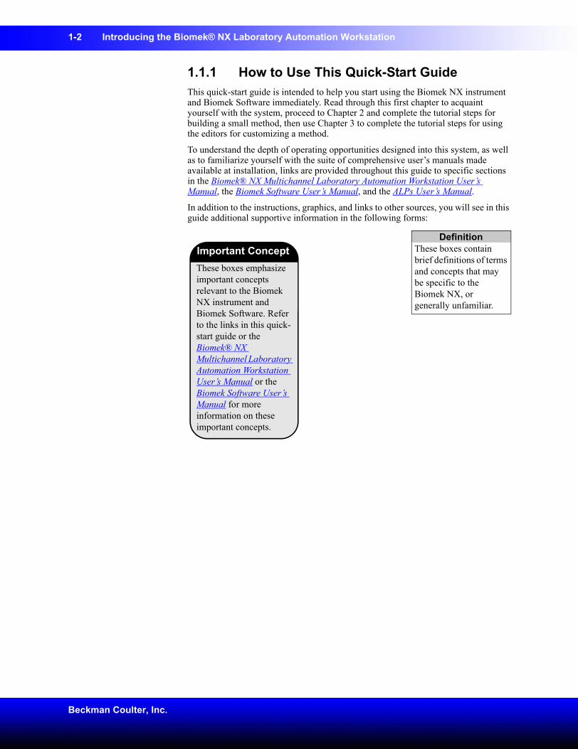
1.1.1 How to Use This Quick-Start GuideThis quick-start guide is intended to help you start using the Biomek NX instrument and Biomek Software immediately. Read through this first chapter to acquaint yourself with the system, proceed to Chapter 2 and complete the tutorial steps for building a small method, then use Chapter 3 to complete the tutorial steps for using the editors for customizing a method.
To understand the depth of operating opportunities designed into this system, as well as to familiarize yourself with the suite of comprehensive user’s manuals made available at installation, links are provided throughout this guide to specific sections in the Biomek® NX Multichannel Laboratory Automation Workstation User’s Manual, the Biomek Software User’s Manual, and the ALPs User’s Manual.
In addition to the instructions, graphics, and links to other sources, you will see in this guide additional supportive information in the following forms:
DefinitionThese boxes contain brief definitions of terms and concepts that may be specific to the Biomek NX, or generally unfamiliar.
These boxes emphasize important concepts relevant to the Biomek NX instrument and Biomek Software. Refer to the links in this quick-start guide or the Biomek® NX Multichannel Laboratory Automation Workstation User’s Manual or the Biomek Software User’s Manual for more information on these important concepts.
Important Concept
Introducing the Biomek® NX Laboratory Automation Workstation 1-3
Biomek® NX Multichannel Laboratory Automation Workstation Quick-Start Guide
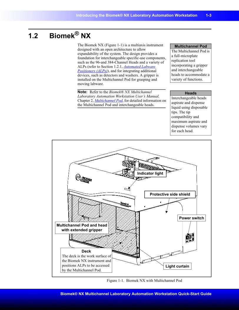
1.2 Biomek® NXThe Biomek NX (Figure 1-1) is a multiaxis instrument designed with an open architecture to allow expandability of the system. The design provides a foundation for interchangeable specific-use components, such as the 96-and 384-Channel Heads and a variety of ALPs (refer to Section 1.2.1, Automated Labware Positioners (ALPs)), and for integrating additional devices, such as detectors and washers. A gripper is installed on the Multichannel Pod for grasping and moving labware.
Note: Refer to the Biomek® NX Multichannel Laboratory Automation Workstation User’s Manual, Chapter 2, Multichannel Pod, for detailed information on the Multichannel Pod and interchangeable heads.
Figure 1-1. Biomek NX with Multichannel Pod
Multichannel PodThe Multichannel Pod is a full-microplate replication tool incorporating a gripper and interchangeable heads to accommodate a variety of functions.
HeadsInterchangeable heads aspirate and dispense liquid using disposable tips. The tip compatibility and maximum aspirate and dispense volumes vary for each head.
Multichannel Pod and head with extended gripper
DeckThe deck is the work surface of the Biomek NX instrument and positions ALPs to be accessed by the Multichannel Pod.
Power switch
Light curtain
Protective side shield
Indicator light
1-4 Introducing the Biomek® NX Laboratory Automation Workstation
Beckman Coulter, Inc.
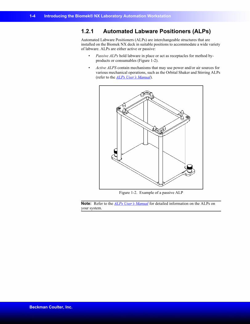
1.2.1 Automated Labware Positioners (ALPs)Automated Labware Positioners (ALPs) are interchangeable structures that are installed on the Biomek NX deck in suitable positions to accommodate a wide variety of labware. ALPs are either active or passive:
• Passive ALPs hold labware in place or act as receptacles for method by-products or consumables (Figure 1-2).
• Active ALPS contain mechanisms that may use power and/or air sources for various mechanical operations, such as the Orbital Shaker and Stirring ALPs (refer to the ALPs User’s Manual).
Figure 1-2. Example of a passive ALP
Note: Refer to the ALPs User’s Manual for detailed information on the ALPs on your system.
Introducing the Biomek® NX Laboratory Automation Workstation 1-5
Biomek® NX Multichannel Laboratory Automation Workstation Quick-Start Guide
1.2.2 Light Curtain and Other Protective BarriersWARNING: To reduce the risk of personal injury, safety shields and light curtain must be in place before operating. Safety shields and light curtain prevent entry into the work area during machine movement.WARNING: Dark non-reflective material affects the sensitivity of the light curtain and adversely impact its effectiveness. Typical lab dress, such as lab coats and latex gloves, do not degrade light curtain operation; however, it is advisable to test the impact of all lab attire on light curtain sensitivity before operating the Biomek NX. The Biomek NX is equipped with protective barriers:
• Front light curtain
• Side protective shields
• Overhead canopy
When an object larger than approximately 1" in diameter penetrates this protective zone, the instrument shuts down immediately, stopping all pod and head operations. Some ALP operations, such as shaking or stirring, continue (refer to the ALPs User’s Manual). When the instrument is sitting idle or in the paused mode, no violations are registered when the protective zone is penetrated.
1-6 Introducing the Biomek® NX Laboratory Automation Workstation
Beckman Coulter, Inc.
1.3 Biomek SoftwareBiomek Software is designed to:
• Do a substantial amount of the method-building work for you.
• Allow you to take as much direct and precise control over the method-building process as you want.
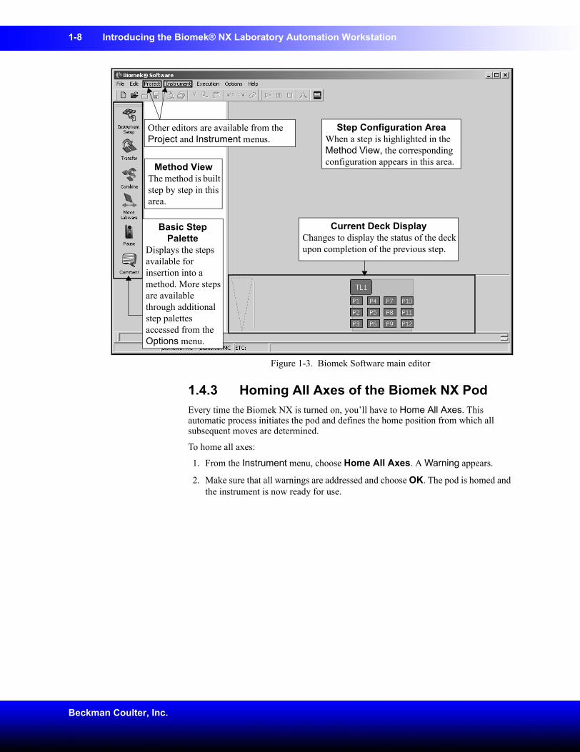
The main editor that appears when the software is launched (Figure 1-3) is used to build and configure methods:
• Each step is dragged and dropped from a Step Palette into the Method View (refer to Chapter 2, Learning to Create Methods for the Biomek® NX).
• When a step in the Method View is highlighted, the corresponding configuration options appear in the Step Configuration Area (refer to Chapter 2, Learning to Create Methods for the Biomek® NX).
• The method is customized to the desired level of precise control via the editors accessed from the Project and Instrument menus (refer to Chapter 3, Using the Editors While Creating Methods).
MethodA method is a series of steps controlling the operations of your Biomek NX.
Step PalettesStep Palettes are panes in the Biomek main editor showing steps available for insertion in a method. They are located on the left of the main editor. Use the Step Palette Builder to add other step palettes. Refer to the Biomek Software User’s Manual, Chapter 29.5, Using the Step Palette Builder for more information.
Introducing the Biomek® NX Laboratory Automation Workstation 1-7
Biomek® NX Multichannel Laboratory Automation Workstation Quick-Start Guide
1.4 Starting the Biomek® NXTo start the Biomek NX, you will follow the instructions in this chapter to turn on the instrument, launch Biomek Software, and home all axes.
1.4.1 Turning On the Biomek NXTo turn on the Biomek NX instrument:
1. Locate the power switch on the right side of the instrument (Figure 1-1).
2. Flip the switch to the On position. The indicator light comes on in solid green.
1.4.2 Launching the SoftwareTo launch Biomek Software:
1. Choose Start>All Programs>Beckman Coulter>Biomek Software.
2. If Accounts & Permissions is enabled (see sidebar), a dialogue box appears requesting you to log in using the user name and password assigned to you by your system administrator. Enter the required information. Your account must have Develop Methods, Develop Projects, and Setup Instrument permissions to complete all parts of this quick-start guide. The Biomek Software main editor appears (Figure 1-3).
Note: If you are logging into Biomek Software for the first time, you must enter a new password. Remember your new password; you will need to enter it each time you access Biomek Software.
Accounts & Permissions
When enabled, Accounts & Permissions is an integrated set of features built into the software to assist users in complying with electronic signature requirements for closed systems. The functionality for Accounts & Permissions is included in the Biomek Software installation and provides control over who can create and run methods, and who may only run validated methods. Refer to the Biomek Software User’s Manual, Chapter 2, Using Accounts & Permissions.
1-8 Introducing the Biomek® NX Laboratory Automation Workstation
Beckman Coulter, Inc.
Figure 1-3. Biomek Software main editor
1.4.3 Homing All Axes of the Biomek NX PodEvery time the Biomek NX is turned on, you’ll have to Home All Axes. This automatic process initiates the pod and defines the home position from which all subsequent moves are determined.
To home all axes:
1. From the Instrument menu, choose Home All Axes. A Warning appears.
2. Make sure that all warnings are addressed and choose OK. The pod is homed and the instrument is now ready for use.
Method ViewThe method is built step by step in this area.
Step Configuration AreaWhen a step is highlighted in the Method View, the corresponding configuration appears in this area.
Other editors are available from the Project and Instrument menus.
Current Deck DisplayChanges to display the status of the deck upon completion of the previous step.
Basic Step Palette
Displays the steps available for insertion into a method. More steps are available through additional step palettes accessed from the Options menu.
2-1
Biomek® NX Multichannel Laboratory Automation Workstation Quick-Start Guide
2 Learning to Create Methods for the Biomek® NX
2.1 OverviewIn this chapter you will be given information and instructions for building a small method using Biomek Software. A method is a series of steps that control the operation of your Biomek NX.
The method you complete in this chapter represents basic operations and is intended simply to familiarize you with the Biomek NX, and to create a basic understanding of method-building opportunities.
Read the information in this chapter and complete the tutorial steps provided. After you have completed the instructions, or if you need additional information along the way, use the links provided to access the suite of user’s manuals provided during installation. These manuals include Biomek Software User’s Manual, Biomek® NX Multichannel Laboratory Automation Workstation User’s Manual, and ALPs User’s Manual. Each manual contains comprehensive information about the possibilities designed into the Biomek NX.
In this chapter, you’ll learn:
• Creating a New Method (Section 2.2)
• Configuring the Instrument Setup Step (Section 2.3)
• Configuring a Transfer Step (Section 2.4)
• Configuring a Move Labware Step (Section 2.5)
• Using the Finish Step (Section 2.6)
• Saving a Method (Section 2.7)
• Running a Method (Section 2.8)
2-2 Learning to Create Methods for the Biomek® NX
Beckman Coulter, Inc.
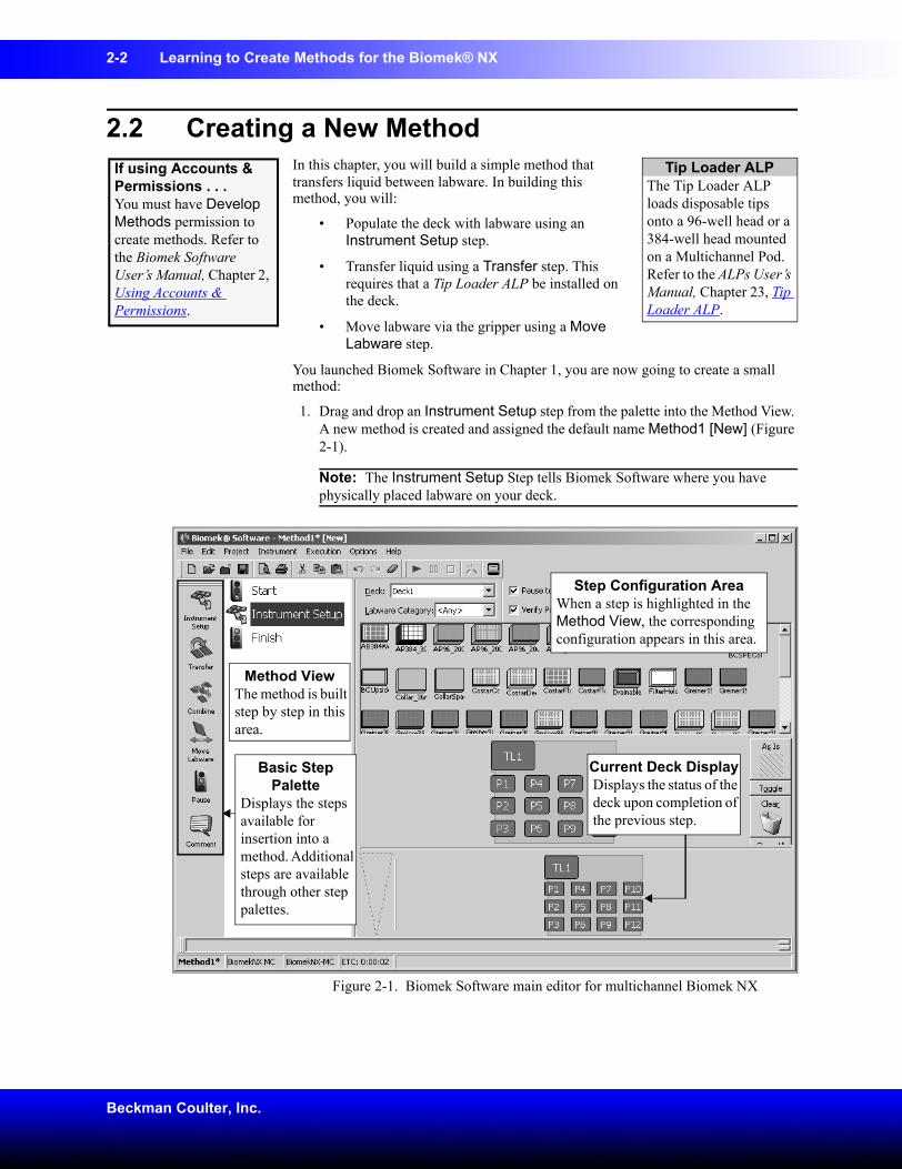
2.2 Creating a New MethodIn this chapter, you will build a simple method that transfers liquid between labware. In building this method, you will:
• Populate the deck with labware using an Instrument Setup step.
• Transfer liquid using a Transfer step. This requires that a Tip Loader ALP be installed on the deck.
• Move labware via the gripper using a Move Labware step.
You launched Biomek Software in Chapter 1, you are now going to create a small method:
1. Drag and drop an Instrument Setup step from the palette into the Method View. A new method is created and assigned the default name Method1 [New] (Figure 2-1).
Note: The Instrument Setup Step tells Biomek Software where you have physically placed labware on your deck.
Figure 2-1. Biomek Software main editor for multichannel Biomek NX
If using Accounts & Permissions . . . You must have Develop Methods permission to create methods. Refer to the Biomek Software User’s Manual, Chapter 2, Using Accounts & Permissions.
Tip Loader ALPThe Tip Loader ALP loads disposable tips onto a 96-well head or a 384-well head mounted on a Multichannel Pod. Refer to the ALPs User’s Manual, Chapter 23, Tip Loader ALP.
Method ViewThe method is built step by step in this area.
Step Configuration AreaWhen a step is highlighted in the Method View, the corresponding configuration appears in this area.
Basic Step Palette
Displays the steps available for insertion into a method. Additional steps are available through other step palettes.
Current Deck DisplayDisplays the status of the deck upon completion of the previous step.
Learning to Create Methods for the Biomek® NX 2-3
Biomek® NX Multichannel Laboratory Automation Workstation Quick-Start Guide
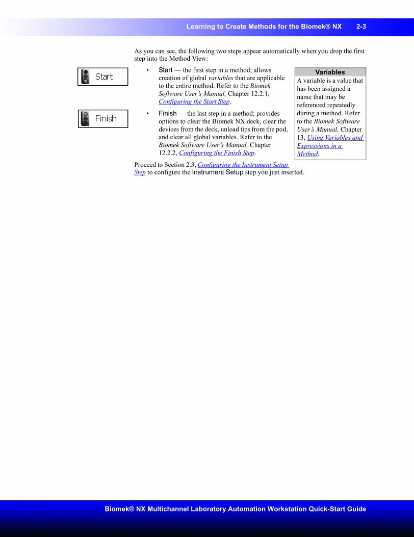
As you can see, the following two steps appear automatically when you drop the first step into the Method View:
• Start — the first step in a method; allows creation of global variables that are applicable to the entire method. Refer to the Biomek Software User’s Manual, Chapter 12.2.1, Configuring the Start Step.
• Finish — the last step in a method; provides options to clear the Biomek NX deck, clear the devices from the deck, unload tips from the pod, and clear all global variables. Refer to the Biomek Software User’s Manual, Chapter 12.2.2, Configuring the Finish Step.
Proceed to Section 2.3, Configuring the Instrument Setup Step to configure the Instrument Setup step you just inserted.
VariablesA variable is a value that has been assigned a name that may be referenced repeatedly during a method. Refer to the Biomek Software User’s Manual, Chapter 13, Using Variables and Expressions in a Method.
2-4 Learning to Create Methods for the Biomek® NX
Beckman Coulter, Inc.
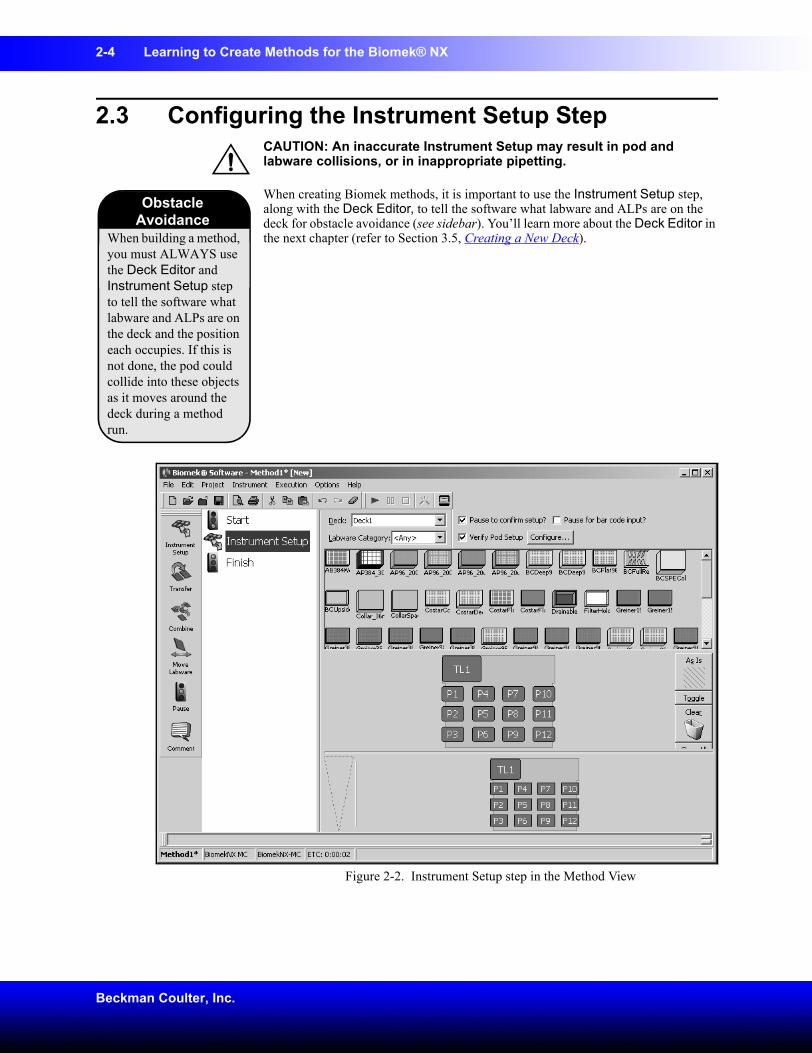
2.3 Configuring the Instrument Setup StepCAUTION: An inaccurate Instrument Setup may result in pod and labware collisions, or in inappropriate pipetting.
When creating Biomek methods, it is important to use the Instrument Setup step, along with the Deck Editor, to tell the software what labware and ALPs are on the deck for obstacle avoidance (see sidebar). You’ll learn more about the Deck Editor in the next chapter (refer to Section 3.5, Creating a New Deck).
Figure 2-2. Instrument Setup step in the Method View
When building a method, you must ALWAYS use the Deck Editor and Instrument Setup step to tell the software what labware and ALPs are on the deck and the position each occupies. If this is not done, the pod could collide into these objects as it moves around the deck during a method run.
Obstacle Avoidance
Learning to Create Methods for the Biomek® NX 2-5
Biomek® NX Multichannel Laboratory Automation Workstation Quick-Start Guide
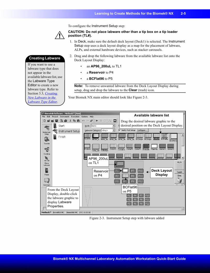
To configure the Instrument Setup step:
CAUTION: Do not place labware other than a tip box on a tip loader position (TL#).1. In Deck, make sure the default deck layout (Deck1) is selected. The Instrument
Setup step uses a deck layout display as a map for the placement of labware, ALPs, and external hardware devices, such as stacker carousels.
2. Drag and drop the following labware from the available labware list onto the Deck Layout Display:
• an AP96_200uL to TL1
• a Reservoir to P4
• a BCFlat96 to P5
Note: To remove unwanted labware from the Deck Layout Display during setup, drag and drop the labware to the Clear (trash) icon.
Your Biomek NX main editor should look like Figure 2-3.
Figure 2-3. Instrument Setup step with labware added
If you want to use a labware type that does not appear in the available labware list, use the Labware Type Editor to create a new labware type. Refer to Section 3.3, Creating New Labware in the Labware Type Editor.
Creating Labware
From the Deck Layout Display, double-click the labware graphic to display Labware Properties.
BCFlat96 on P5
Reservoir on P4
AP96_200uL on TL1
Available labware listDrag the desired labware graphic to the desired position on the Deck Layout Display.
Deck Layout Display
2-6 Learning to Create Methods for the Biomek® NX
Beckman Coulter, Inc.
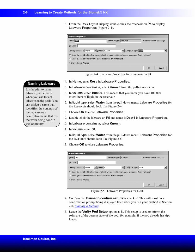
3. From the Deck Layout Display, double-click the reservoir on P4 to display Labware Properties (Figure 2-4).
Figure 2-4. Labware Properties for Reservoir on P4
4. In Name, enter Resv in Labware Properties.
5. In Labware contains a, select Known from the pull-down menu.
6. In volume, enter 100000. This means that you know you have 100,000 microliters of liquid in the reservoir.
7. In liquid type, select Water from the pull-down menu. Labware Properties for the Reservoir should look like Figure 2-4.
8. Choose OK to close Labware Properties.
9. Double-click the labware on P5 and name it Dest1 in Labware Properties.
10. In Labware contains a, select Known.
11. In volume, enter 50.
12. In liquid type, select Water from the pull-down menu. Labware Properties for the BCFlat96 should look like Figure 2-5.
13. Choose OK to close Labware Properties.
Figure 2-5. Labware Properties for Dest1
14. Confirm that Pause to confirm setup? is checked. This will result in a confirmation prompt being displayed later when you run your method in Section 2.8, Running a Method.
15. Leave the Verify Pod Setup option as is. This setup is used to inform the software of the current state of the pod; for example, if the pod already has tips loaded.
It is helpful to name labware, particularly when you use lots of labware on the deck. You can assign a name that identifies the contents of the labware or a descriptive name that fits the work being done in the laboratory.
Naming Labware
Learning to Create Methods for the Biomek® NX 2-7
Biomek® NX Multichannel Laboratory Automation Workstation Quick-Start Guide
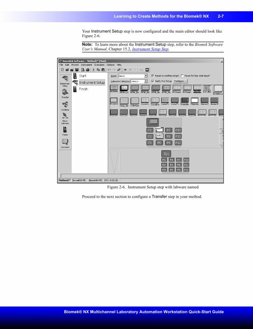
Your Instrument Setup step is now configured and the main editor should look like Figure 2-6.
Note: To learn more about the Instrument Setup step, refer to the Biomek Software User’s Manual, Chapter 15.2, Instrument Setup Step.
Figure 2-6. Instrument Setup step with labware named
Proceed to the next section to configure a Transfer step in your method.
2-8 Learning to Create Methods for the Biomek® NX
Beckman Coulter, Inc.
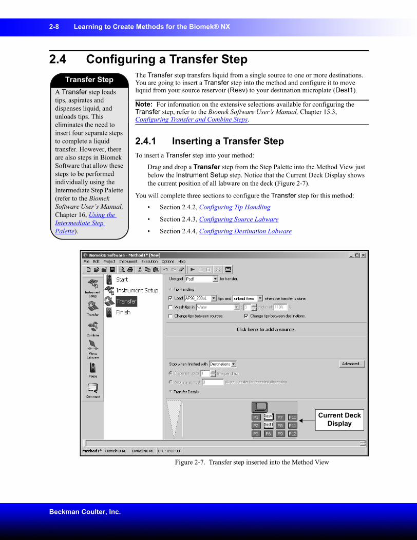
2.4 Configuring a Transfer StepThe Transfer step transfers liquid from a single source to one or more destinations. You are going to insert a Transfer step into the method and configure it to move liquid from your source reservoir (Resv) to your destination microplate (Dest1).
Note: For information on the extensive selections available for configuring the Transfer step, refer to the Biomek Software User’s Manual, Chapter 15.3, Configuring Transfer and Combine Steps.
2.4.1 Inserting a Transfer StepTo insert a Transfer step into your method:
Drag and drop a Transfer step from the Step Palette into the Method View just below the Instrument Setup step. Notice that the Current Deck Display shows the current position of all labware on the deck (Figure 2-7).
You will complete three sections to configure the Transfer step for this method:
• Section 2.4.2, Configuring Tip Handling
• Section 2.4.3, Configuring Source Labware
• Section 2.4.4, Configuring Destination Labware
Figure 2-7. Transfer step inserted into the Method View
A Transfer step loads tips, aspirates and dispenses liquid, and unloads tips. This eliminates the need to insert four separate steps to complete a liquid transfer. However, there are also steps in Biomek Software that allow these steps to be performed individually using the Intermediate Step Palette (refer to the Biomek Software User’s Manual, Chapter 16, Using the Intermediate Step Palette).
Transfer Step
Current Deck Display
Learning to Create Methods for the Biomek® NX 2-9
Biomek® NX Multichannel Laboratory Automation Workstation Quick-Start Guide
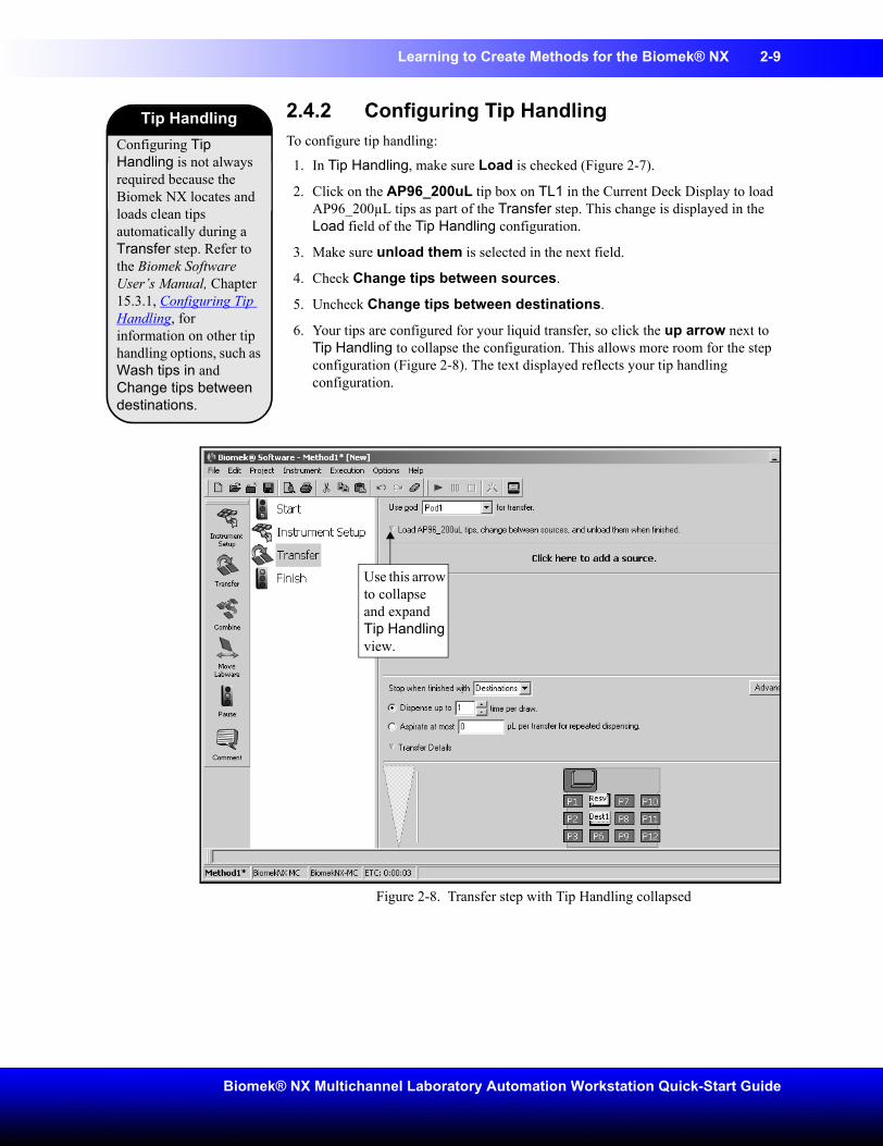
2.4.2 Configuring Tip HandlingTo configure tip handling:
1. In Tip Handling, make sure Load is checked (Figure 2-7).
2. Click on the AP96_200uL tip box on TL1 in the Current Deck Display to load AP96_200µL tips as part of the Transfer step. This change is displayed in the Load field of the Tip Handling configuration.
3. Make sure unload them is selected in the next field.
4. Check Change tips between sources.
5. Uncheck Change tips between destinations.
6. Your tips are configured for your liquid transfer, so click the up arrow next to Tip Handling to collapse the configuration. This allows more room for the step configuration (Figure 2-8). The text displayed reflects your tip handling configuration.
Figure 2-8. Transfer step with Tip Handling collapsed
Configuring Tip Handling is not always required because the Biomek NX locates and loads clean tips automatically during a Transfer step. Refer to the Biomek Software User’s Manual, Chapter 15.3.1, Configuring Tip Handling, for information on other tip handling options, such as Wash tips in and Change tips between destinations.
Tip Handling
Use this arrow to collapse and expand Tip Handling view.
2-10 Learning to Create Methods for the Biomek® NX
Beckman Coulter, Inc.
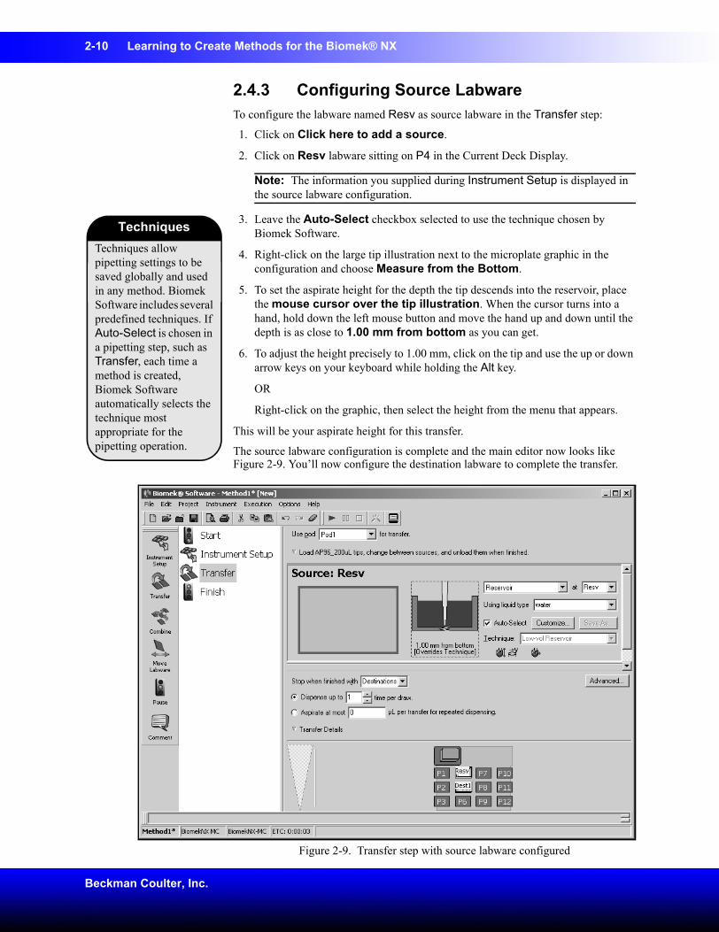
2.4.3 Configuring Source LabwareTo configure the labware named Resv as source labware in the Transfer step:
1. Click on Click here to add a source.
2. Click on Resv labware sitting on P4 in the Current Deck Display.
Note: The information you supplied during Instrument Setup is displayed in the source labware configuration.
3. Leave the Auto-Select checkbox selected to use the technique chosen by Biomek Software.
4. Right-click on the large tip illustration next to the microplate graphic in the configuration and choose Measure from the Bottom.
5. To set the aspirate height for the depth the tip descends into the reservoir, place the mouse cursor over the tip illustration. When the cursor turns into a hand, hold down the left mouse button and move the hand up and down until the depth is as close to 1.00 mm from bottom as you can get.
6. To adjust the height precisely to 1.00 mm, click on the tip and use the up or down arrow keys on your keyboard while holding the Alt key.
OR
Right-click on the graphic, then select the height from the menu that appears.
This will be your aspirate height for this transfer.
The source labware configuration is complete and the main editor now looks like Figure 2-9. You’ll now configure the destination labware to complete the transfer.
Figure 2-9. Transfer step with source labware configured
Techniques allow pipetting settings to be saved globally and used in any method. Biomek Software includes several predefined techniques. If Auto-Select is chosen in a pipetting step, such as Transfer, each time a method is created, Biomek Software automatically selects the technique most appropriate for the pipetting operation.
Techniques
Learning to Create Methods for the Biomek® NX 2-11
Biomek® NX Multichannel Laboratory Automation Workstation Quick-Start Guide
2.4.4 Configuring Destination LabwareTo configure the labware named Dest1 as destination labware in the Transfer step:
1. Before you configure the destination labware, click the down arrow in Transfer Details located just above the Current Deck Display to collapse that section. You will not be making any changes to the options in this section.
2. Click on Dest1 sitting on P5 in the Current Deck Display. This one operation accomplishes the same task as steps 1 and 2 of Section 1.5.2 Configuring Source Labware.)
Note: Notice that the source labware configuration is collapsed and replaced with a text summary of the setup. If you want to reopen the source configuration, click anywhere in the collapsed area.
3. The Volume field is highlighted, which allows you to designate the amount of liquid to be dispensed. For this tutorial, you’ll transfer 100 µL; so, type 100 into the Volume field.
Note: The volume is measured in microliters (µL) automatically and indicates the amount of liquid that will be dispensed (100 µL) into each of the 96 wells; so, in this case, you’re dispensing a total of 9600 µL.
4. Right-click on the large tip illustration and choose Measure from Bottom.
5. Set the dispense height in the large tip illustration to 1.00 mm from bottom, using the same technique as you used for setting the aspirate height.
Note: If you accidentally open too many destination configurations, right-click on the title above the graphic of the plate in the configuration. Click on Delete from the popup menu and the entire configuration goes away.
Transfer details include a stop condition for transfer operations; a repeat pipetting configuration; and a maximum tolerance in timing between transfer operations. Refer to the Biomek Software User’s Manual, Chapter 15.3.4, Configuring Transfer Details.
Transfer Details
2-12 Learning to Create Methods for the Biomek® NX
Beckman Coulter, Inc.
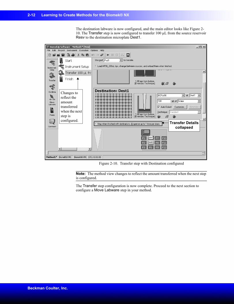
The destination labware is now configured, and the main editor looks like Figure 2-10. The Transfer step is now configured to transfer 100 µL from the source reservoir Resv to the destination microplate Dest1.
Figure 2-10. Transfer step with Destination configured
Note: The method view changes to reflect the amount transferred when the next step is configured.
The Transfer step configuration is now complete. Proceed to the next section to configure a Move Labware step in your method.
Transfer Details collapsed
Changes to reflect the amount transferred when the next step is configured.
Learning to Create Methods for the Biomek® NX 2-13
Biomek® NX Multichannel Laboratory Automation Workstation Quick-Start Guide
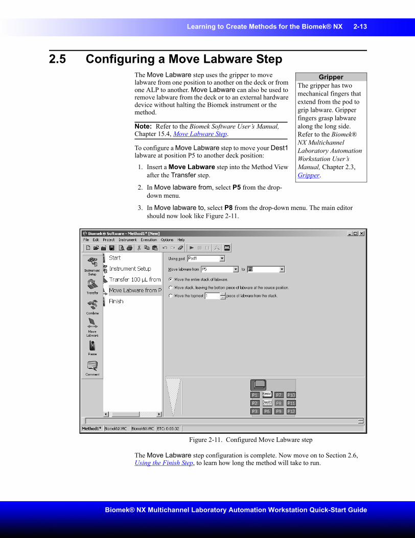
2.5 Configuring a Move Labware StepThe Move Labware step uses the gripper to move labware from one position to another on the deck or from one ALP to another. Move Labware can also be used to remove labware from the deck or to an external hardware device without halting the Biomek instrument or the method.
Note: Refer to the Biomek Software User’s Manual, Chapter 15.4, Move Labware Step.
To configure a Move Labware step to move your Dest1 labware at position P5 to another deck position:
1. Insert a Move Labware step into the Method View after the Transfer step.
2. In Move labware from, select P5 from the drop-down menu.
3. In Move labware to, select P8 from the drop-down menu. The main editor should now look like Figure 2-11.
Figure 2-11. Configured Move Labware step
The Move Labware step configuration is complete. Now move on to Section 2.6, Using the Finish Step, to learn how long the method will take to run.
GripperThe gripper has two mechanical fingers that extend from the pod to grip labware. Gripper fingers grasp labware along the long side. Refer to the Biomek® NX Multichannel Laboratory Automation Workstation User’s Manual, Chapter 2.3, Gripper.
2-14 Learning to Create Methods for the Biomek® NX
Beckman Coulter, Inc.
2.6 Using the Finish StepUse the Finish step to see how long it will take to run your method.
1. Click on the Finish step in the Method View.
2. Check the status bar at the bottom of the main editor for a display of the Estimated Time for Completion (ETC). For this method, the ETC is approximately 0:41.
Note: Your ETC may vary slightly. That’s OK. Refer to the Biomek Software User’s Manual, Chapter 12.2.2, Configuring the Finish Step.
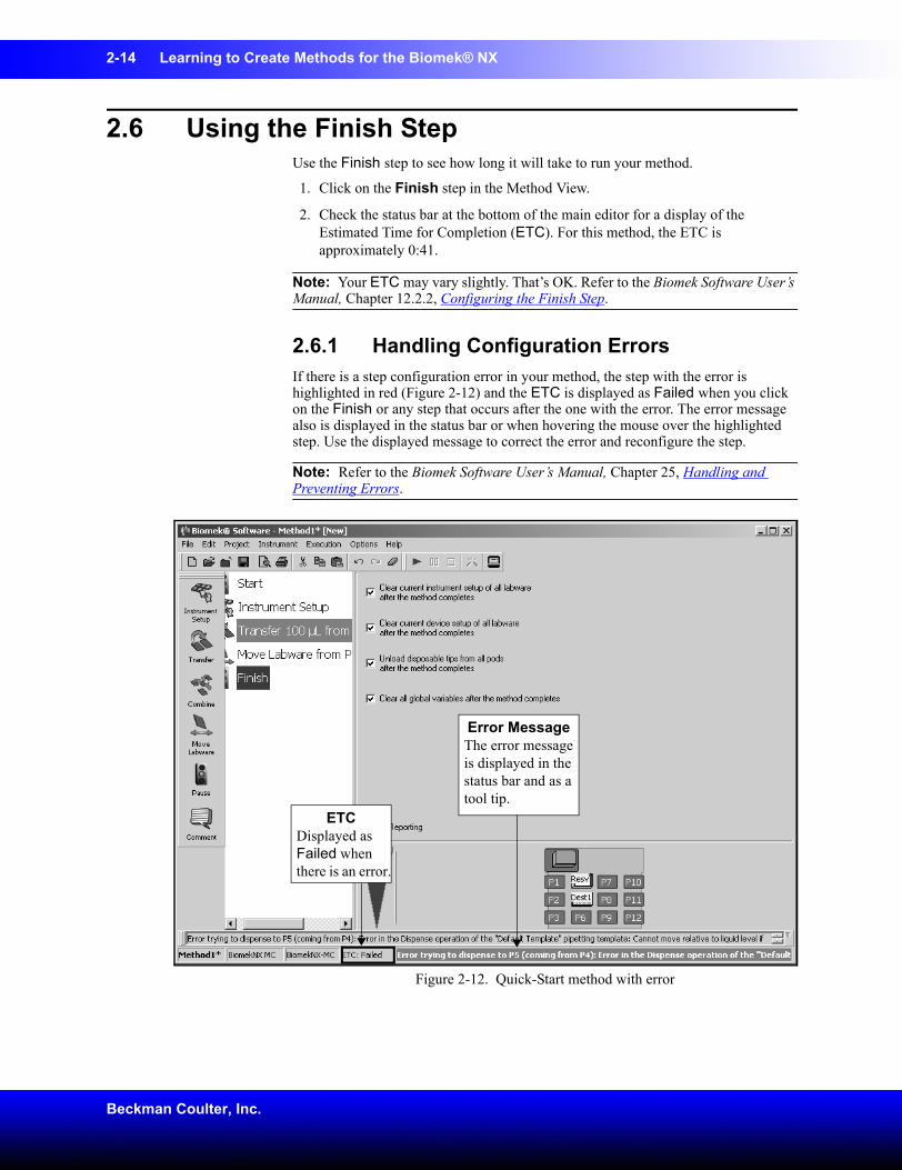
2.6.1 Handling Configuration ErrorsIf there is a step configuration error in your method, the step with the error is highlighted in red (Figure 2-12) and the ETC is displayed as Failed when you click on the Finish or any step that occurs after the one with the error. The error message also is displayed in the status bar or when hovering the mouse over the highlighted step. Use the displayed message to correct the error and reconfigure the step.
Note: Refer to the Biomek Software User’s Manual, Chapter 25, Handling and Preventing Errors.
Figure 2-12. Quick-Start method with error
Error MessageThe error message is displayed in the status bar and as a tool tip.
ETCDisplayed as Failed when there is an error.
Learning to Create Methods for the Biomek® NX 2-15
Biomek® NX Multichannel Laboratory Automation Workstation Quick-Start Guide
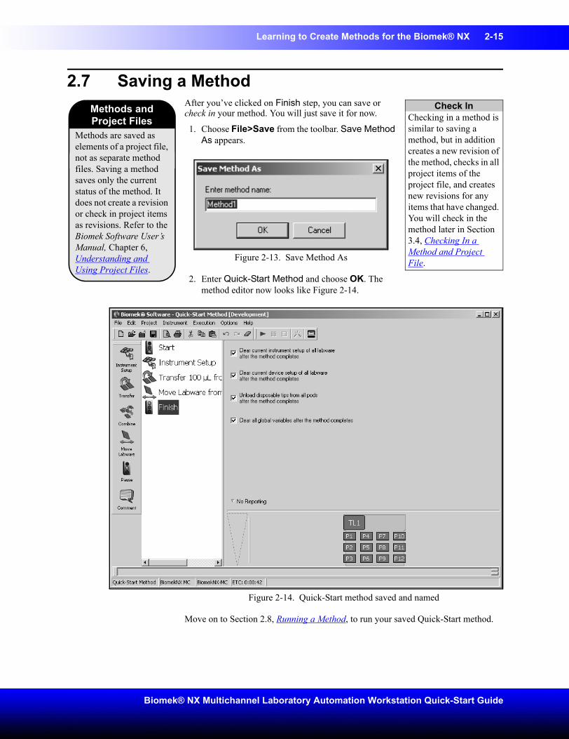
2.7 Saving a MethodAfter you’ve clicked on Finish step, you can save or check in your method. You will just save it for now.
1. Choose File>Save from the toolbar. Save Method As appears.
Figure 2-13. Save Method As
2. Enter Quick-Start Method and choose OK. The method editor now looks like Figure 2-14.
Figure 2-14. Quick-Start method saved and named
Move on to Section 2.8, Running a Method, to run your saved Quick-Start method.
Methods and Project Files
Methods are saved as elements of a project file, not as separate method files. Saving a method saves only the current status of the method. It does not create a revision or check in project items as revisions. Refer to the Biomek Software User’s Manual, Chapter 6, Understanding and Using Project Files.
Check InChecking in a method is similar to saving a method, but in addition creates a new revision of the method, checks in all project items of the project file, and creates new revisions for any items that have changed. You will check in the method later in Section 3.4, Checking In a Method and Project File.
2-16 Learning to Create Methods for the Biomek® NX
Beckman Coulter, Inc.
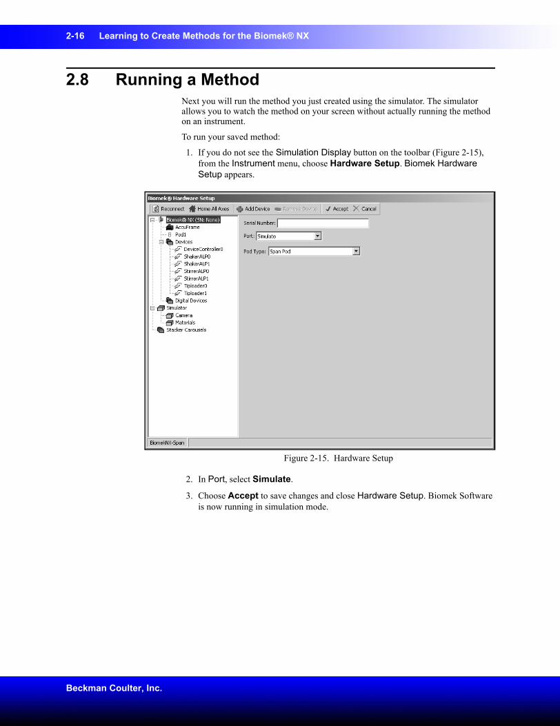
2.8 Running a MethodNext you will run the method you just created using the simulator. The simulator allows you to watch the method on your screen without actually running the method on an instrument.
To run your saved method:
1. If you do not see the Simulation Display button on the toolbar (Figure 2-15), from the Instrument menu, choose Hardware Setup. Biomek Hardware Setup appears.
Figure 2-15. Hardware Setup
2. In Port, select Simulate.
3. Choose Accept to save changes and close Hardware Setup. Biomek Software is now running in simulation mode.
Learning to Create Methods for the Biomek® NX 2-17
Biomek® NX Multichannel Laboratory Automation Workstation Quick-Start Guide
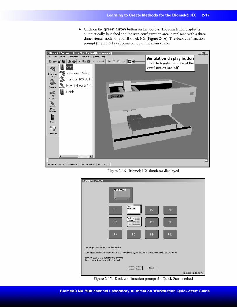
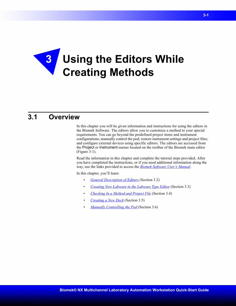
4. Click on the green arrow button on the toolbar. The simulation display is automatically launched and the step configuration area is replaced with a three-dimensional model of your Biomek NX (Figure 2-16). The deck confirmation prompt (Figure 2-17) appears on top of the main editor.
Figure 2-16. Biomek NX simulator displayed
Figure 2-17. Deck confirmation prompt for Quick Start method
Simulation display buttonClick to toggle the view of the simulator on and off.

2-18 Learning to Create Methods for the Biomek® NX
Beckman Coulter, Inc.
5. Choose OK. The prompt closes and the method continues. View the method on screen as it proceeds in the simulator. The method can also be followed in the Method View as steps are highlighted in green as they are executed.
Note: If you are running this method on your instrument instead of the simulator, make sure that the physical deck layout matches the expected deck layout shown in the deck confirmation prompt before you choose OK.
You can proceed directly to Chapter 3, Using the Editors While Creating Methods, to learn about the editors you’ll use for customizing your methods.
3-1
Biomek® NX Multichannel Laboratory Automation Workstation Quick-Start Guide
3 Using the Editors While Creating Methods
3.1 OverviewIn this chapter you will be given information and instructions for using the editors in the Biomek Software. The editors allow you to customize a method to your special requirements. You can go beyond the predefined project items and instrument configurations; manually control the pod; restore instrument settings and project files; and configure external devices using specific editors. The editors are accessed from the Project or Instrument menus located on the toolbar of the Biomek main editor (Figure 3-1).
Read the information in this chapter and complete the tutorial steps provided. After you have completed the instructions, or if you need additional information along the way, use the links provided to access the Biomek Software User’s Manual.
In this chapter, you’ll learn:
• General Description of Editors (Section 3.2)
• Creating New Labware in the Labware Type Editor (Section 3.3)
• Checking In a Method and Project File (Section 3.4)
• Creating a New Deck (Section 3.5)
• Manually Controlling the Pod (Section 3.6)
3-2 Using the Editors While Creating Methods
Beckman Coulter, Inc.
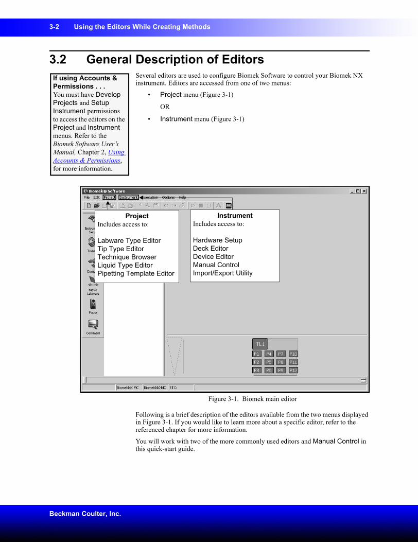
3.2 General Description of EditorsSeveral editors are used to configure Biomek Software to control your Biomek NX instrument. Editors are accessed from one of two menus:
• Project menu (Figure 3-1)
OR
• Instrument menu (Figure 3-1)
Figure 3-1. Biomek main editor
Following is a brief description of the editors available from the two menus displayed in Figure 3-1. If you would like to learn more about a specific editor, refer to the referenced chapter for more information.
You will work with two of the more commonly used editors and Manual Control in this quick-start guide.
If using Accounts & Permissions . . . You must have Develop Projects and Setup Instrument permissions to access the editors on the Project and Instrument menus. Refer to the Biomek Software User’s Manual, Chapter 2, Using Accounts & Permissions, for more information.
ProjectIncludes access to:
Labware Type Editor Tip Type EditorTechnique BrowserLiquid Type EditorPipetting Template Editor
InstrumentIncludes access to:
Hardware SetupDeck EditorDevice EditorManual ControlImport/Export Utility
Using the Editors While Creating Methods 3-3
Biomek® NX Multichannel Laboratory Automation Workstation Quick-Start Guide
3.2.1 Project MenuThe editors on the Project menu (Figure 3-1) allow project items to be created, copied, revised, and renamed. They include the following:
• Labware Type Editor — allows you to add new labware types, copy labware types, delete labware types, rename labware types, and edit labware type properties (refer to the Biomek Software User’s Manual, Chapter 7, Creating and Modifying Tip and Labware Types).
Note: Refer to Section 3.3, Creating New Labware in the Labware Type Editor, in this quick-start guide to follow step-by-step instructions to create a new piece of labware.
• Tip Type Editor — allows you to add new tip types, remove tip types, and change tip properties (refer to the Biomek Software User’s Manual, Chapter 7, Creating and Modifying Tip and Labware Types).
• Technique Browser — allows you to customize techniques for your specific needs and save them for use in future methods (refer to the Biomek Software User’s Manual, Chapter 9, Understanding and Creating Techniques).
• Liquid Type Editor — allows you to create new liquid types or to modify existing liquid types (refer to the Biomek Software User’s Manual, Chapter 8, Understanding and Creating Liquid Types).
• Pipetting Template Editor — allows you to create or modify pipetting templates that configure the precise actions during pipetting operations (refer to the Biomek Software User’s Manual, Chapter 10, Using the Pipetting Template Editor).
3.2.2 Instrument MenuThe editors on the Instrument menu (Figure 3-1) allow instrument configuration to be changed. They include the following:
• Hardware Setup — if you change the configuration of your instrument, it is used to install, configure, and remove other devices (refer to the Biomek® NX Multichannel Laboratory Automation Workstation User’s Manual, Chapter 3.1.1, Accessing Hardware Setup).
• Deck Editor — used to define and change deck configurations (refer to the Biomek Software User’s Manual, Chapter 5, Preparing and Managing the Deck).
Note: Refer to Section 3.5, Creating a New Deck, in this quick-start guide to follow step-by-step instructions to create a new deck layout in the software.
• Device Editor — external devices may be integrated to your Biomek NX. In order to use the integrated device, it must be configured through the Device Editor (refer to the Biomek Software User’s Manual, Chapter 22.4.1, Configuring Devices Using the Device Editor).
• Manual Control — allows you to control the movement of the bridge, head, and gripper independently of a method. It is used to control the pod when framing the deck or gripper and when recovering from errors (refer to the
3-4 Using the Editors While Creating Methods
Beckman Coulter, Inc.
Biomek® NX Multichannel Laboratory Automation Workstation User’s Manual, Chapter 5, Manually Controlling the Biomek® NX in Biomek Software).
Note: Refer to Section 3.6, Manually Controlling the Pod, in this quick-start guide to learn how to manually move a pod.
• Import/Export Utility — allows you to import and export instrument settings (decks, framing tools, and pod settings) as import files (.imp) (refer to the Biomek Software User’s Manual, Chapter 3, Using Instrument Files and Settings).
Using the Editors While Creating Methods 3-5
Biomek® NX Multichannel Laboratory Automation Workstation Quick-Start Guide
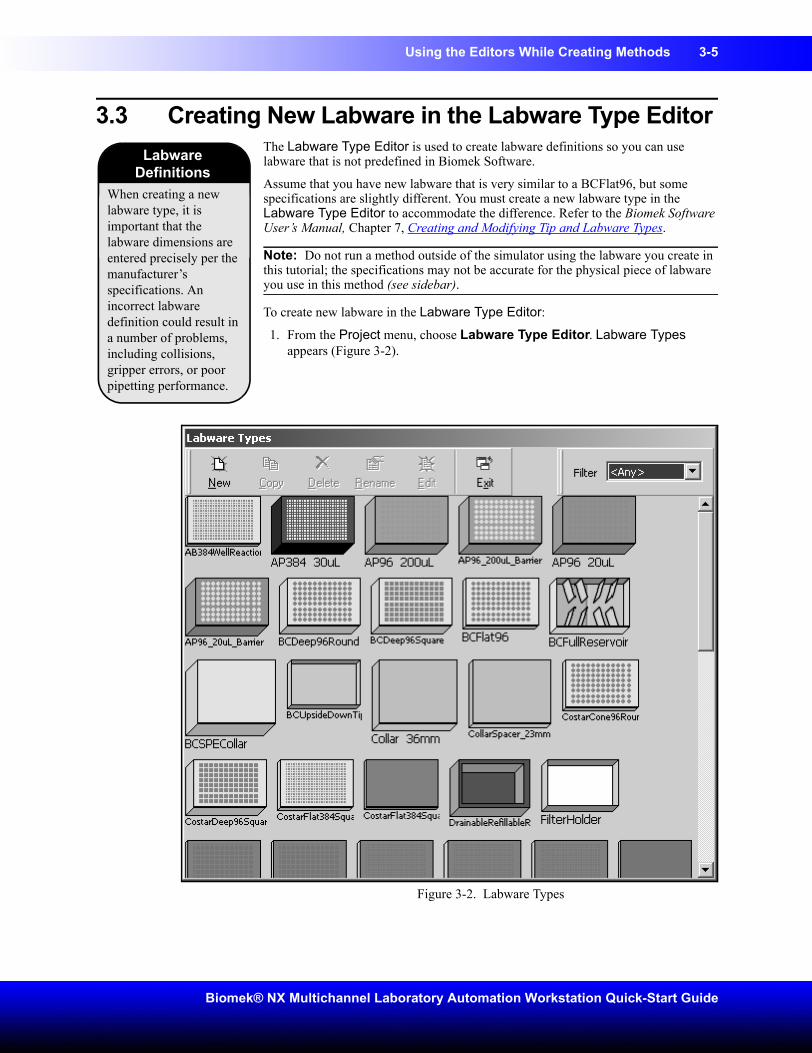
3.3 Creating New Labware in the Labware Type EditorThe Labware Type Editor is used to create labware definitions so you can use labware that is not predefined in Biomek Software.
Assume that you have new labware that is very similar to a BCFlat96, but some specifications are slightly different. You must create a new labware type in the Labware Type Editor to accommodate the difference. Refer to the Biomek Software User’s Manual, Chapter 7, Creating and Modifying Tip and Labware Types.
Note: Do not run a method outside of the simulator using the labware you create in this tutorial; the specifications may not be accurate for the physical piece of labware you use in this method (see sidebar).
To create new labware in the Labware Type Editor:
1. From the Project menu, choose Labware Type Editor. Labware Types appears (Figure 3-2).
Figure 3-2. Labware Types
When creating a new labware type, it is important that the labware dimensions are entered precisely per the manufacturer’s specifications. An incorrect labware definition could result in a number of problems, including collisions, gripper errors, or poor pipetting performance.
Labware Definitions
3-6 Using the Editors While Creating Methods
Beckman Coulter, Inc.
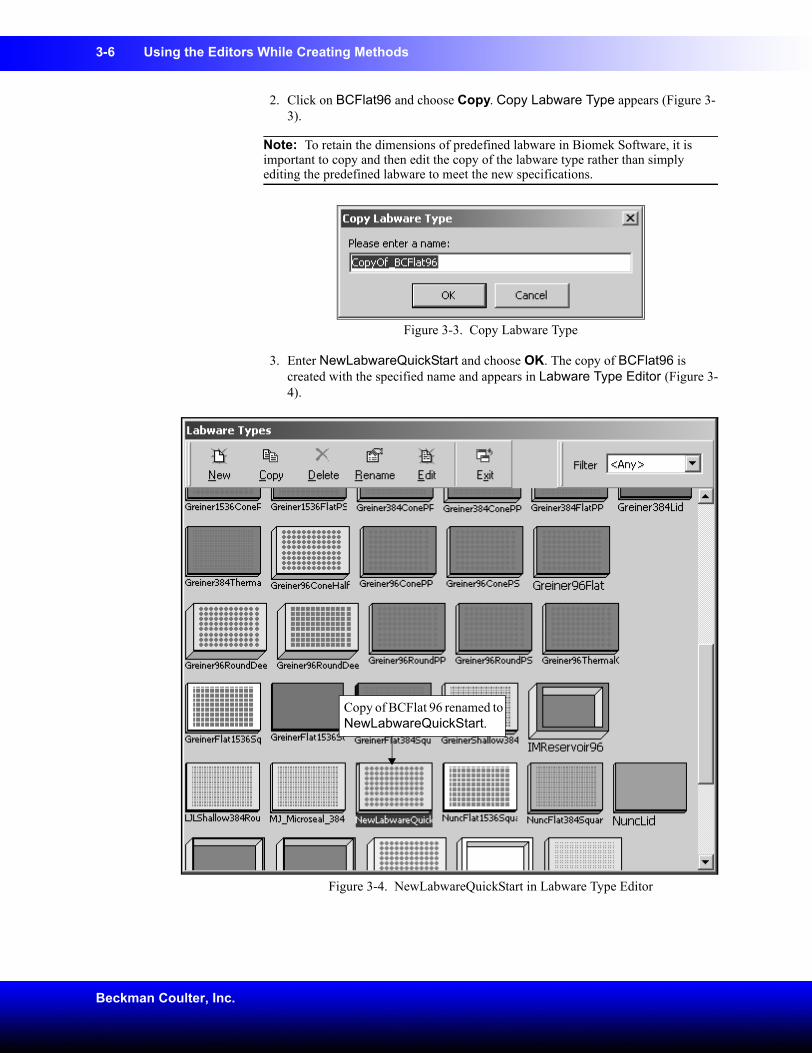
2. Click on BCFlat96 and choose Copy. Copy Labware Type appears (Figure 3-3).
Note: To retain the dimensions of predefined labware in Biomek Software, it is important to copy and then edit the copy of the labware type rather than simply editing the predefined labware to meet the new specifications.
Figure 3-3. Copy Labware Type
3. Enter NewLabwareQuickStart and choose OK. The copy of BCFlat96 is created with the specified name and appears in Labware Type Editor (Figure 3-4).
Figure 3-4. NewLabwareQuickStart in Labware Type Editor
Copy of BCFlat 96 renamed to NewLabwareQuickStart.
Using the Editors While Creating Methods 3-7
Biomek® NX Multichannel Laboratory Automation Workstation Quick-Start Guide
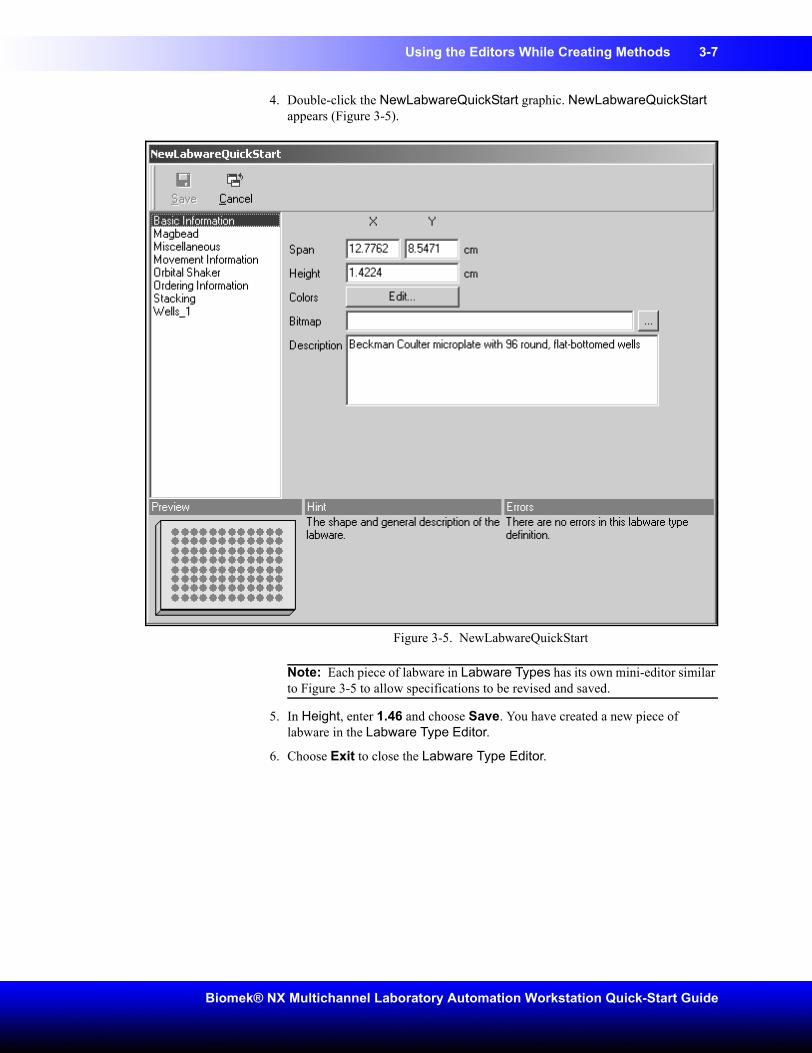
4. Double-click the NewLabwareQuickStart graphic. NewLabwareQuickStart appears (Figure 3-5).
Figure 3-5. NewLabwareQuickStart
Note: Each piece of labware in Labware Types has its own mini-editor similar to Figure 3-5 to allow specifications to be revised and saved.
5. In Height, enter 1.46 and choose Save. You have created a new piece of labware in the Labware Type Editor.
6. Choose Exit to close the Labware Type Editor.
3-8 Using the Editors While Creating Methods
Beckman Coulter, Inc.
3.4 Checking In a Method and Project FileChecking in a method is similar to saving a method, but also creates a revision record of the method, checks in all project items of the project file, and creates new revisions for any items that have changed.
You will check in your quick-start method, along with the new labware you just created.
To check in your method with the new labware:
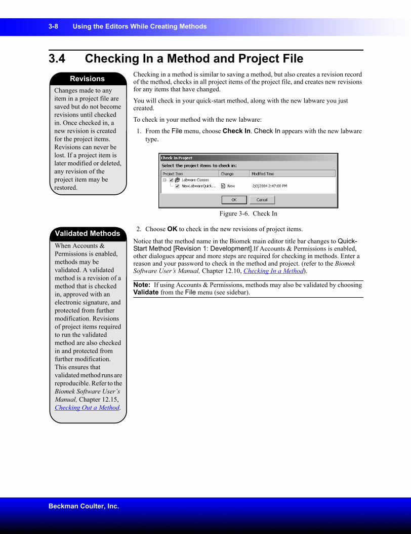
1. From the File menu, choose Check In. Check In appears with the new labware type.
Figure 3-6. Check In
2. Choose OK to check in the new revisions of project items.
Notice that the method name in the Biomek main editor title bar changes to Quick-Start Method [Revision 1: Development].If Accounts & Permissions is enabled, other dialogues appear and more steps are required for checking in methods. Enter a reason and your password to check in the method and project. (refer to the Biomek Software User’s Manual, Chapter 12.10, Checking In a Method).
Note: If using Accounts & Permissions, methods may also be validated by choosing Validate from the File menu (see sidebar).
Changes made to any item in a project file are saved but do not become revisions until checked in. Once checked in, a new revision is created for the project items. Revisions can never be lost. If a project item is later modified or deleted, any revision of the project item may be restored.
Revisions
When Accounts & Permissions is enabled, methods may be validated. A validated method is a revision of a method that is checked in, approved with an electronic signature, and protected from further modification. Revisions of project items required to run the validated method are also checked in and protected from further modification. This ensures that validated method runs are reproducible. Refer to the Biomek Software User’s Manual, Chapter 12.15, Checking Out a Method.
Validated Methods
Using the Editors While Creating Methods 3-9
Biomek® NX Multichannel Laboratory Automation Workstation Quick-Start Guide
3.5 Creating a New DeckA deck in Biomek Software refers to the software representation of the physical Biomek NX deck. The Deck Editor is used to define and change deck configurations, and stores deck information used for multiple methods. A deck also stores framing information and device associations for each position on the deck.
Note: Refer to the Biomek Software User’s Manual, Chapter 5, Preparing and Managing the Deck.
Assume you have added a Trash ALP to your instrument deck and now must create another deck in the Deck Editor that reflects that addition to the physical deck.
To create a new deck in the Deck Editor:
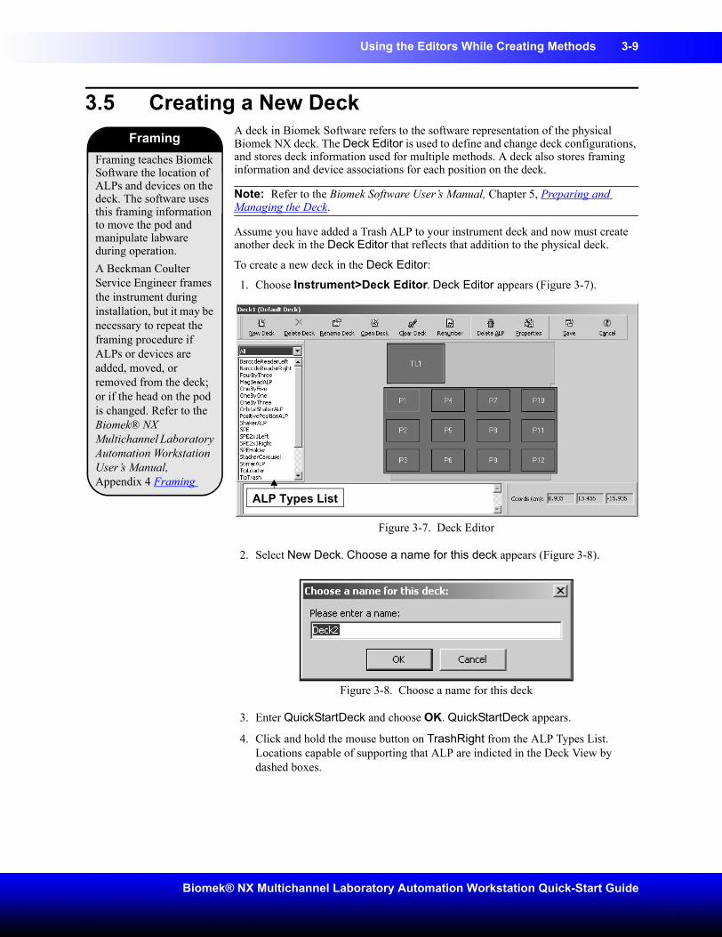
1. Choose Instrument>Deck Editor. Deck Editor appears (Figure 3-7).
Figure 3-7. Deck Editor
2. Select New Deck. Choose a name for this deck appears (Figure 3-8).
Figure 3-8. Choose a name for this deck
3. Enter QuickStartDeck and choose OK. QuickStartDeck appears.
4. Click and hold the mouse button on TrashRight from the ALP Types List. Locations capable of supporting that ALP are indicted in the Deck View by dashed boxes.
Framing teaches Biomek Software the location of ALPs and devices on the deck. The software uses this framing information to move the pod and manipulate labware during operation. A Beckman Coulter Service Engineer frames the instrument during installation, but it may be necessary to repeat the framing procedure if ALPs or devices are added, moved, or removed from the deck; or if the head on the pod is changed. Refer to the Biomek® NX Multichannel Laboratory Automation Workstation User’s Manual, Appendix 4 Framing
Framing
ALP Types List
3-10 Using the Editors While Creating Methods
Beckman Coulter, Inc.
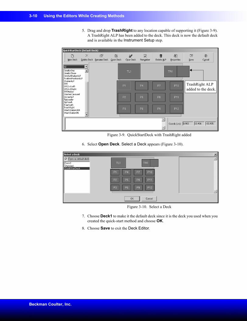
5. Drag and drop TrashRight to any location capable of supporting it (Figure 3-9). A TrashRight ALP has been added to the deck. This deck is now the default deck and is available in the Instrument Setup step.
Figure 3-9. QuickStartDeck with TrashRight added
6. Select Open Deck. Select a Deck appears (Figure 3-10).
Figure 3-10. Select a Deck
7. Choose Deck1 to make it the default deck since it is the deck you used when you created the quick-start method and choose OK.
8. Choose Save to exit the Deck Editor.
TrashRight ALP added to the deck.
Using the Editors While Creating Methods 3-11
Biomek® NX Multichannel Laboratory Automation Workstation Quick-Start Guide
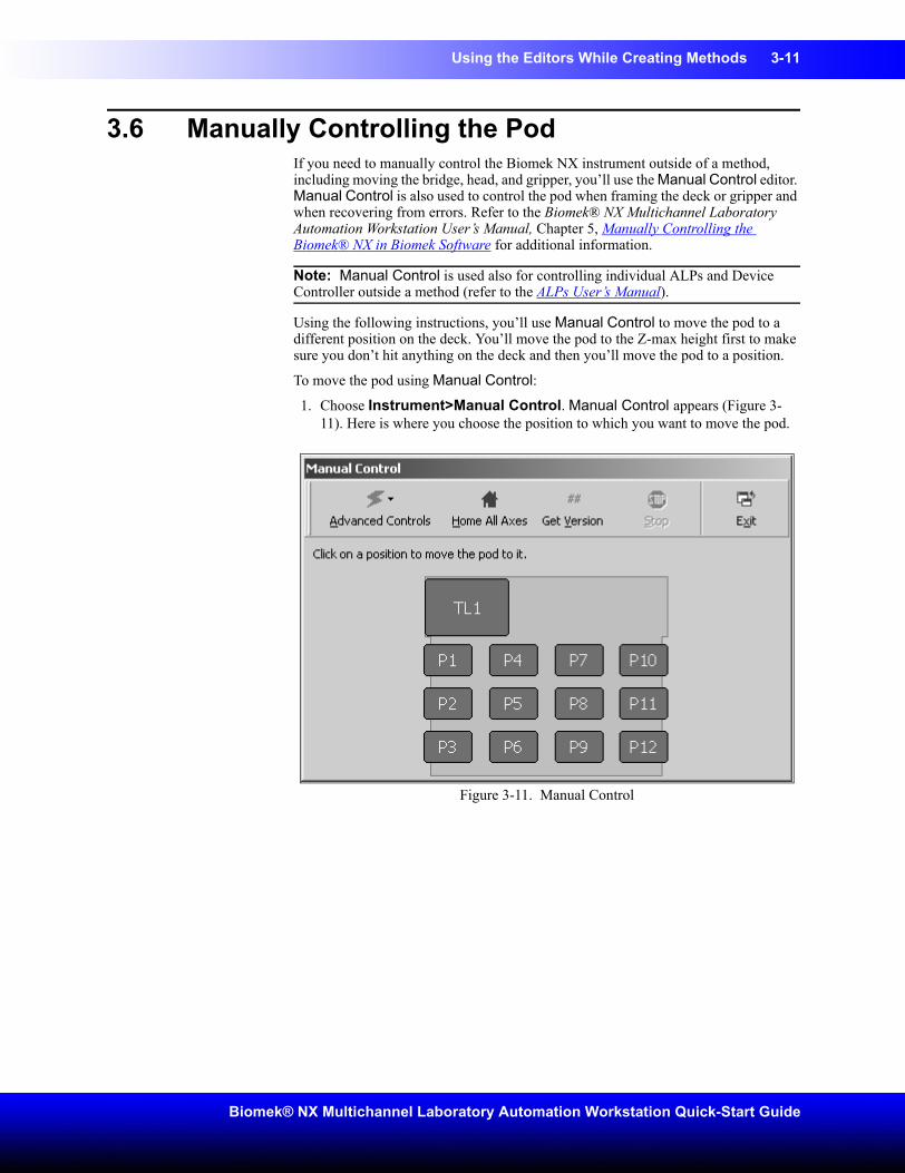
3.6 Manually Controlling the PodIf you need to manually control the Biomek NX instrument outside of a method, including moving the bridge, head, and gripper, you’ll use the Manual Control editor. Manual Control is also used to control the pod when framing the deck or gripper and when recovering from errors. Refer to the Biomek® NX Multichannel Laboratory Automation Workstation User’s Manual, Chapter 5, Manually Controlling the Biomek® NX in Biomek Software for additional information.
Note: Manual Control is used also for controlling individual ALPs and Device Controller outside a method (refer to the ALPs User’s Manual).
Using the following instructions, you’ll use Manual Control to move the pod to a different position on the deck. You’ll move the pod to the Z-max height first to make sure you don’t hit anything on the deck and then you’ll move the pod to a position.
To move the pod using Manual Control:
1. Choose Instrument>Manual Control. Manual Control appears (Figure 3-11). Here is where you choose the position to which you want to move the pod.
Figure 3-11. Manual Control
3-12 Using the Editors While Creating Methods
Beckman Coulter, Inc.
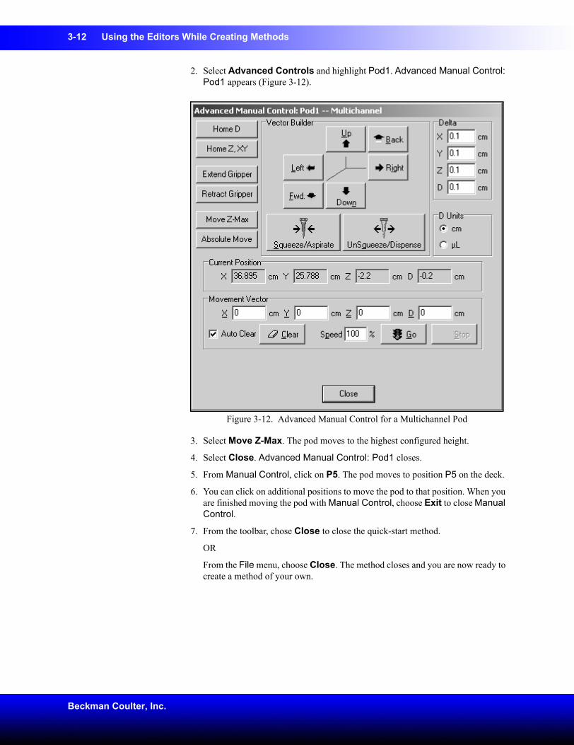
2. Select Advanced Controls and highlight Pod1. Advanced Manual Control: Pod1 appears (Figure 3-12).
Figure 3-12. Advanced Manual Control for a Multichannel Pod
3. Select Move Z-Max. The pod moves to the highest configured height.
4. Select Close. Advanced Manual Control: Pod1 closes.
5. From Manual Control, click on P5. The pod moves to position P5 on the deck.
6. You can click on additional positions to move the pod to that position. When you are finished moving the pod with Manual Control, choose Exit to close Manual Control.
7. From the toolbar, chose Close to close the quick-start method.
OR
From the File menu, choose Close. The method closes and you are now ready to create a method of your own.
Using the Editors While Creating Methods 3-13
Biomek® NX Multichannel Laboratory Automation Workstation Quick-Start Guide
3.7 Quick-Start Guide SummaryCongratulations! You’ve just completed this quick-start guide.
You’ve completed:
• a small method
• steps using the editors
• steps creating some new project items
• steps to manually control the Biomek NX
If you’ve used the links to other manuals, you’ve also learned where to find hardware information on the Biomek NX, ALPs, and more information on Biomek Software.
Enjoy your new Biomek NX Multichannel Laboratory Automation Workstation.
