bircraft actuator accessories and options
TRANSCRIPT
BirCraft GEARED MOTORS - LINEAR ACTUATORS - CONTROLS
t: + (27) 011 468 1881 c: +(27) 074 465 1744
e: [email protected] w: www.BirCraft.co.za
Page 1 of 21
- Over 40 Years of Supplying Africa -
Address: 320 B Percheron Road, Kyalami, Midrand, 1684 GPS Coordinates: S 25.98115º / E 028.06869º GUIDELINE DIMENSIONS ONLY
Linear Actuators
Accessories and Options
Index:
A Stainless steel version Page 14
AA Industry version Page 15
B Bellows boot Page 13
CG Bellflange with coupling (on request)
E Viton seals Page 14
FX Anticorrosion painting Page 15
FXC Cataphoresis Page 15
G Safety nut Page 13
H Handwheel Page 14
L Anti rotation device Page 11
MM Manual driving for ALI1 and ALI1-P models Page 14
N Manual driving with safety limit switch Page 14
O Body integrated Swivelling shafts (on request)
OA Front Swivelling plate (on request)
OP Rear Swivelling plate (on request)
P Handwheel and safety-switch Page 14
PO Rear-pipe for swinging movement (on request)
S Torque limiter Page 12
T Additional shaft Page 12
Z Low noise Page 14
ACCORDING TO THE OPTIONS DESIRED, ADD THE IDENTIFICATION LETTERS AT THE END OF THE ORDERING KEY RELATED TO THE
PRODUCT CHOSEN
Examples:
ALI5 / 0300 / M01 / CA-400-50-T-71-2-0,55 / B5+AB/ M1-FC1 / 1 / E05 / 2FC0 / P0T01A / P1 / A1
ALI5 / 0300 / M01 / CA-400-50-T-71-2-0,55 / B5+AB/ M1-FC1 / 1 / E05 / 2FC0 / P0T01A / P1 / A1 + AA + S+T
ALI5 / 0300 / M01 / CA-400-50-T-71-2-0,55 / B5+AB/ M1-FC1 / 1 / E05 / 2FC0 / P0T01A / P1 / A1 / S+T/ N.DIS
ORDERING KEY FOR STANDARD PRODUCT
ORDERING KEY FOR STANDARD PRODUCT + OPTIONS
ORDERING KEY WITH NO STANDARD OPTIONS
Page 2 of 21
- Over 40 Years of Supplying Africa -
Linear Actuators
Accessories and Options
T: 011 468 1881 | www.BirCraft.co.za
C: 074 465 1744 | e: [email protected]
Address: 320 B Percheron Road, Kyalami, Midrand, 1684
GPS Coordinates: S 25.98115º / E 028.06869º
GUIDELINE DIMENSIONS ONLY
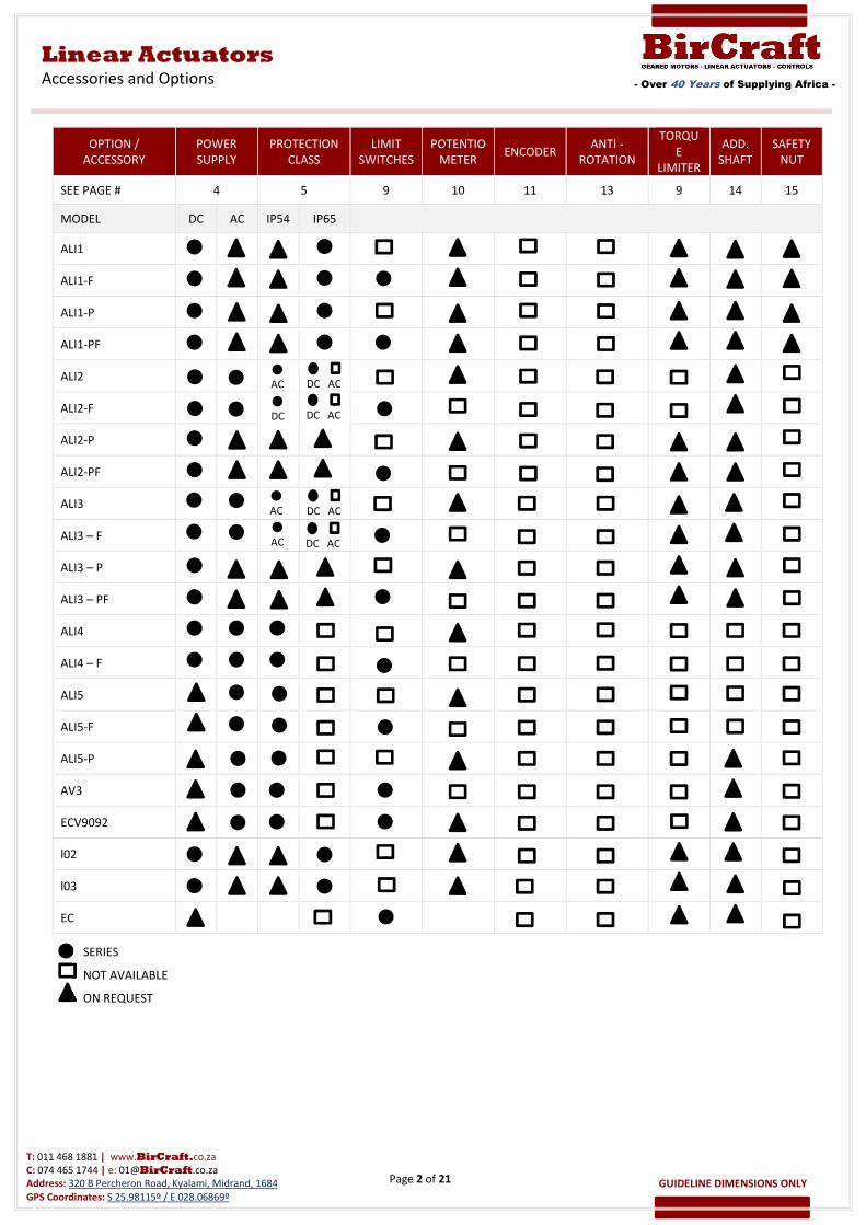
OPTION /
ACCESSORY
POWER
SUPPLY
PROTECTION
CLASS
LIMIT
SWITCHES
POTENTIO
METER ENCODER
ANTI -
ROTATION
TORQU
E
LIMITER
ADD.
SHAFT
SAFETY
NUT
SEE PAGE # 4 5 9 10 11 13 9 14 15
MODEL DC AC IP54 IP65
ALI1
ALI1-F
ALI1-P
ALI1-PF
ALI2
ALI2-F
ALI2-P
ALI2-PF
ALI3
ALI3 – F
ALI3 – P
ALI3 – PF
ALI4
ALI4 – F
ALI5
ALI5-F
ALI5-P
AV3
ECV9092
l02
l03
EC
DC AC
AC
DC
AC
SERIES
NOT AVAILABLE
ON REQUEST
DC AC
DC AC
DC AC
AC
Page 3 of 21
- Over 40 Years of Supplying Africa -
Linear Actuators
Accessories and Options
T: 011 468 1881 | www.BirCraft.co.za
C: 074 465 1744 | e: [email protected]
Address: 320 B Percheron Road, Kyalami, Midrand, 1684
GPS Coordinates: S 25.98115º / E 028.06869º
GUIDELINE DIMENSIONS ONLY
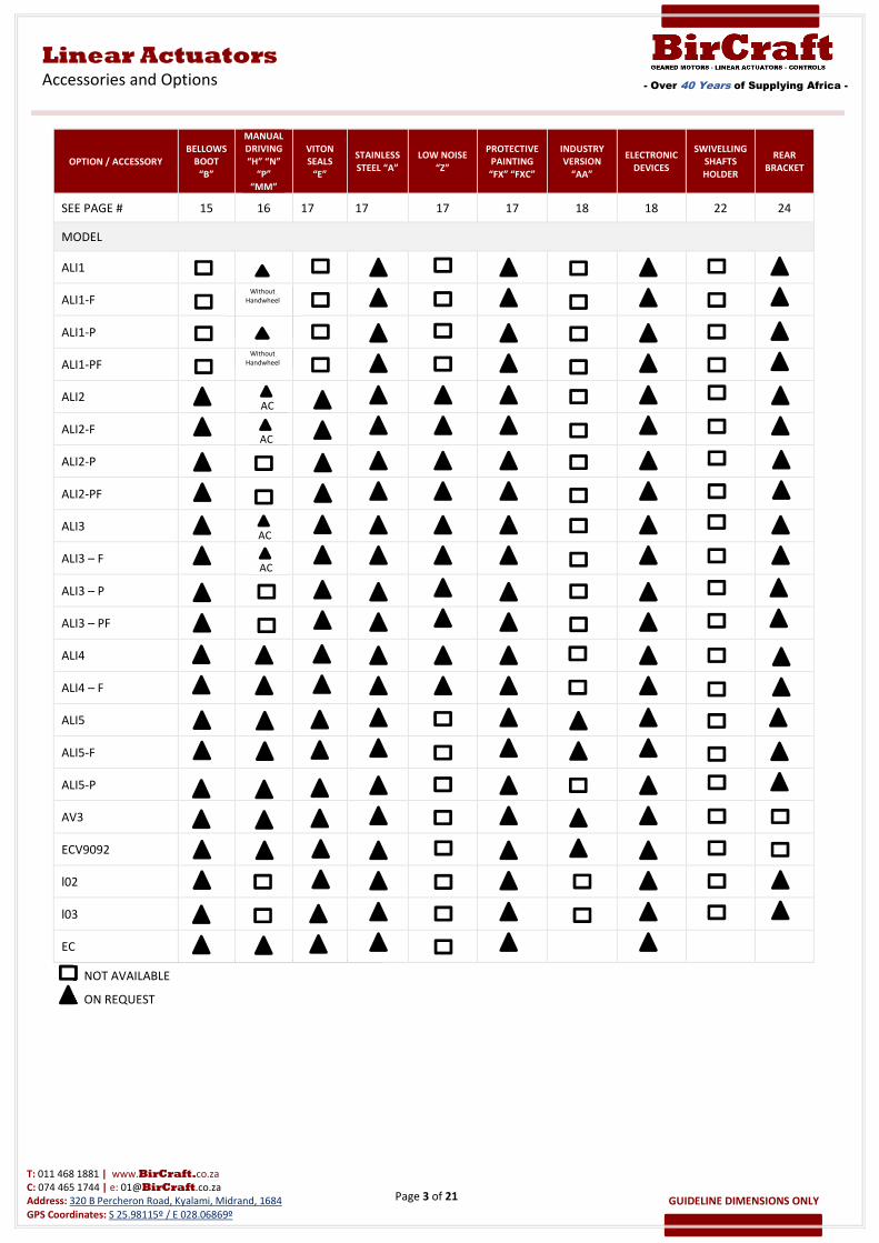
OPTION / ACCESSORY
BELLOWS
BOOT
“B”
MANUAL
DRIVING
“H” “N”
“P”
“MM”
VITON
SEALS
“E”
STAINLESS
STEEL “A”
LOW NOISE
“Z”
PROTECTIVE
PAINTING
“FX” “FXC”
INDUSTRY
VERSION
“AA”
ELECTRONIC
DEVICES
SWIVELLING
SHAFTS
HOLDER
REAR
BRACKET
SEE PAGE # 15 16 17 17 17 17 18 18 22 24
MODEL
ALI1
ALI1-F
ALI1-P
ALI1-PF
ALI2
ALI2-F
ALI2-P
ALI2-PF
ALI3
ALI3 – F
ALI3 – P
ALI3 – PF
ALI4
ALI4 – F
ALI5
ALI5-F
ALI5-P
AV3
ECV9092
l02
l03
EC
Without
Handwheel
AC
AC
NOT AVAILABLE
ON REQUEST
AC
AC
Without
Handwheel
Page 4 of 21
- Over 40 Years of Supplying Africa -
Linear Actuators
Accessories and Options
T: 011 468 1881 | www.BirCraft.co.za
C: 074 465 1744 | e: [email protected]
Address: 320 B Percheron Road, Kyalami, Midrand, 1684
GPS Coordinates: S 25.98115º / E 028.06869º
GUIDELINE DIMENSIONS ONLY
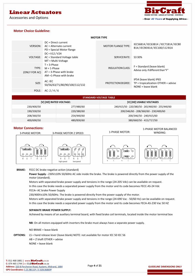
Motor Choice Guideline:
MOTOR TYPE
VERSION:
DC = Direct current
AC = Alternate current
PD = Special Motor flange
MOTOR FLANGE TYPE: IEC56B14 / IEC63B14 / IEC71B14 / IEC80
B14 / IEC90 B14 / IEC100/112 B14
VOLTAGE:
DC = V12 / V24
SERVICE RATE: S3 30% AC = Standard Voltage table
MT = Multi-Voltage
TYPE:
(ONLY FOR AC)
T = 3-Phase
M = 1-Phase
AT = 3-Phase with brake
AM =1-Phase with brake
INSULATION CLASS:
F = Standard (leave blank)
Advise only if different than “F”
SIZE: AC: IEC
50/56/63/71/80/90/100/112/132 PROTECTION DEGREE:
IP54 (leave blank) IP65
TP = tropicalization OTHER = advise
NONE = leave blank
POLE: AC: 2 / 4 / 6
STANDARD VOLTAGE TABLE
[V] [HZ] RATED VOLTAGE: [V] [HZ] USABLE VOLTAGES
230/400/50 277/480/60 240/415/50 - 220/380/50 - 265/460/60 - 255/440/60
190/330/50 220/380/60 200/346/60 - 208/360/60 - 230/400/60
208/360/50 254/440/60 200/346/50 - 240/415/60
400/690/50 480/830/60 380/660/50 - 415/717/50
Motor Connections:
BRAKE: FECC DC brake negative action (standard)
Power Supply - 230V±10% 50/60Hz AC side inside the brake. The brake is powered directly from the power supply of the
motor (standard).
Motors with separated brake power supply and tensions in the range (24-205 Vdc) can be available on request.
In this case the brake needs a separated power supply from the motor and its code becomes FECC-AS-24 Vdc
FECA= AC brake Power Supply
230/400V±10% 50/60Hz. The brake is powered directly from the power supply of the motor.
Motors with separated brake power supply and tensions in the range (24-690 Vac - 50/60 Hz) can be available on request.
In this case the brake needs a separated power supply from the motor and its code becomes FECA-AS-230 Vac 50 HZ
SEPARATE BRAKE POWER SUPPLY:
Achieved by means of an auxiliary terminal board, with fixed brake coil terminals, located inside the motor terminal box
NB: On all motors equipped with inverters the brake must always have a separate power supply.
NO BRAKE = leave blank
OPTIONS: LS = hand release lever (leave blank) NOTE: not available for motor IEC 50 IEC 56
AB = 2’shaft OTHER = advise
NONE = leave blank
1-PHASE MOTOR:
high speed low speed
3-PHASE MOTOR: 3-PHASE MOTOR 2 SPEED:
1-PHASE MOTOR BALANCED
WINDING:
Page 5 of 21
- Over 40 Years of Supplying Africa -
Linear Actuators
Accessories and Options
T: 011 468 1881 | www.BirCraft.co.za
C: 074 465 1744 | e: [email protected]
Address: 320 B Percheron Road, Kyalami, Midrand, 1684
GPS Coordinates: S 25.98115º / E 028.06869º
GUIDELINE DIMENSIONS ONLY
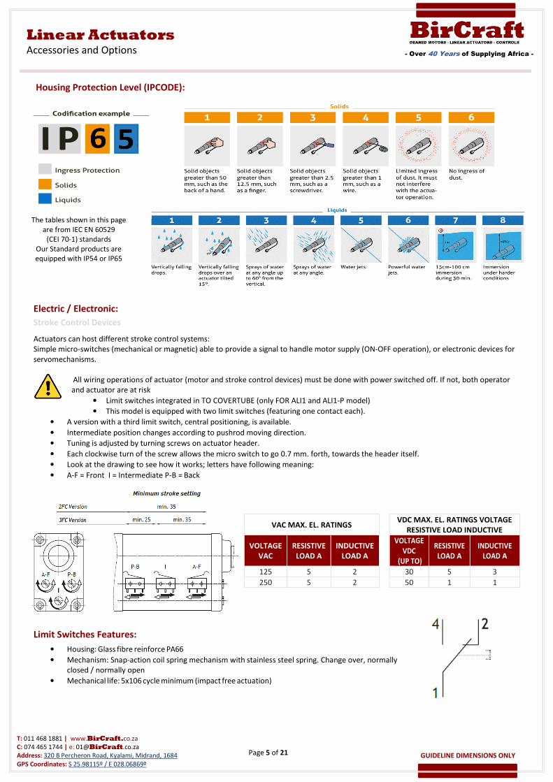
Housing Protection Level (IPCODE):
Electric / Electronic:
Stroke Control Devices
Actuators can host different stroke control systems:
Simple micro-switches (mechanical or magnetic) able to provide a signal to handle motor supply (ON-OFF operation), or electronic devices for
servomechanisms.
All wiring operations of actuator (motor and stroke control devices) must be done with power switched off. If not, both operator
and actuator are at risk
• Limit switches integrated in TO COVERTUBE (only FOR ALI1 and ALI1-P model)
• This model is equipped with two limit switches (featuring one contact each).
• A version with a third limit switch, central positioning, is available.
• Intermediate position changes according to pushrod moving direction.
• Tuning is adjusted by turning screws on actuator header.
• Each clockwise turn of the screw allows the micro switch to go 0.7 mm. forth, towards the header itself.
• Look at the drawing to see how it works; letters have following meaning:
• A-F = Front I = Intermediate P-B = Back
Limit Switches Features:
• Housing: Glass fibre reinforce PA66
• Mechanism: Snap-action coil spring mechanism with stainless steel spring. Change over, normally
closed / normally open
• Mechanical life: 5x10⁶ cycle minimum (impact free actuation)
VAC MAX. EL. RATINGS VDC MAX. EL. RATINGS VOLTAGE
RESISTIVE LOAD INDUCTIVE
VOLTAGE
VAC
RESISTIVE
LOAD A
INDUCTIVE
LOAD A
VOLTAGE
VDC
(UP TO)
RESISTIVE
LOAD A
INDUCTIVE
LOAD A
125 5 2 30 5 3
250 5 2 50 1 1
The tables shown in this page
are from IEC EN 60529
(CEI 70-1) standards
Our Standard products are
equipped with IP54 or IP65
Page 6 of 21
- Over 40 Years of Supplying Africa -
Linear Actuators
Accessories and Options
T: 011 468 1881 | www.BirCraft.co.za
C: 074 465 1744 | e: [email protected]
Address: 320 B Percheron Road, Kyalami, Midrand, 1684
GPS Coordinates: S 25.98115º / E 028.06869º
GUIDELINE DIMENSIONS ONLY
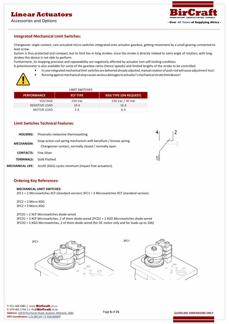
Integrated Mechanical Limit Switches:
Changeover single-contact, cam-actuated micro-switches integrated onto actuator gearbox, getting movement by a small gearing connected to
lead screw.
System is thus protected and compact, but its limit lies in long strokes: since the stroke is directly related to cams angle of rotation, with long
strokes this device is not able to perform.
Furthermore, its stopping precision and repeatability are negatively affected by actuator non-self-locking condition.
A potentiometer is also available for some of the gearbox ratios (hence speeds) and limited lengths of the stroke to be controlled.
• In case integrated mechanical limit switches are delivered already adjusted, manual rotation of push-rod will cause adjustment loss!
• Running against mechanical stop causes serious damages to actuator’s mechanical stroke limit device!
Limit Switches Technical Features:
HOUSING: Phoenolic-melamine thermosetting
MECHANISM: Snap-action coil spring mechanism with beryllium / bronze spring.
Changeover contact, normally closed / normally open
CONTACTS: Fine Silver
TERMINALS: Gold Flashed
MECHANICAL LIFE: 3x10⁵ (XGG) cycles minimum (impact free actuation).
Ordering Key References:
MECHANICAL LIMIT SWITCHES:
2FC1 = 2 Microswitches XCF (standard version) 3FC1 = 3 Microswitches XCF (standard version)
2FC2 = 2 Micro XGG
3FC2 = 3 Micro XGG
2FCD1 = 2 XCF Microswitches diode-wired
3FCD1 = 3 XCF Microswitches, 2 of them diode-wired 2FCD2 = 2 XGG Microswitches diode-wired
3FCD2 = 3 XGG Microswitches, 2 of them diode-wired (for DC motor only and for loads up to 10A)
LIMIT SWITCHES
PERFORMANCE XCF TYPE XGG TYPE (ON REQUEST)
VOLTAGE 250 Vac 230 Vac / 30 Vdc
RESISTIVE LOAD 10 A 16 A
MOTOR LOAD 2 A 6 A
Page 7 of 21
- Over 40 Years of Supplying Africa -
Linear Actuators
Accessories and Options
T: 011 468 1881 | www.BirCraft.co.za
C: 074 465 1744 | e: [email protected]
Address: 320 B Percheron Road, Kyalami, Midrand, 1684
GPS Coordinates: S 25.98115º / E 028.06869º
GUIDELINE DIMENSIONS ONLY
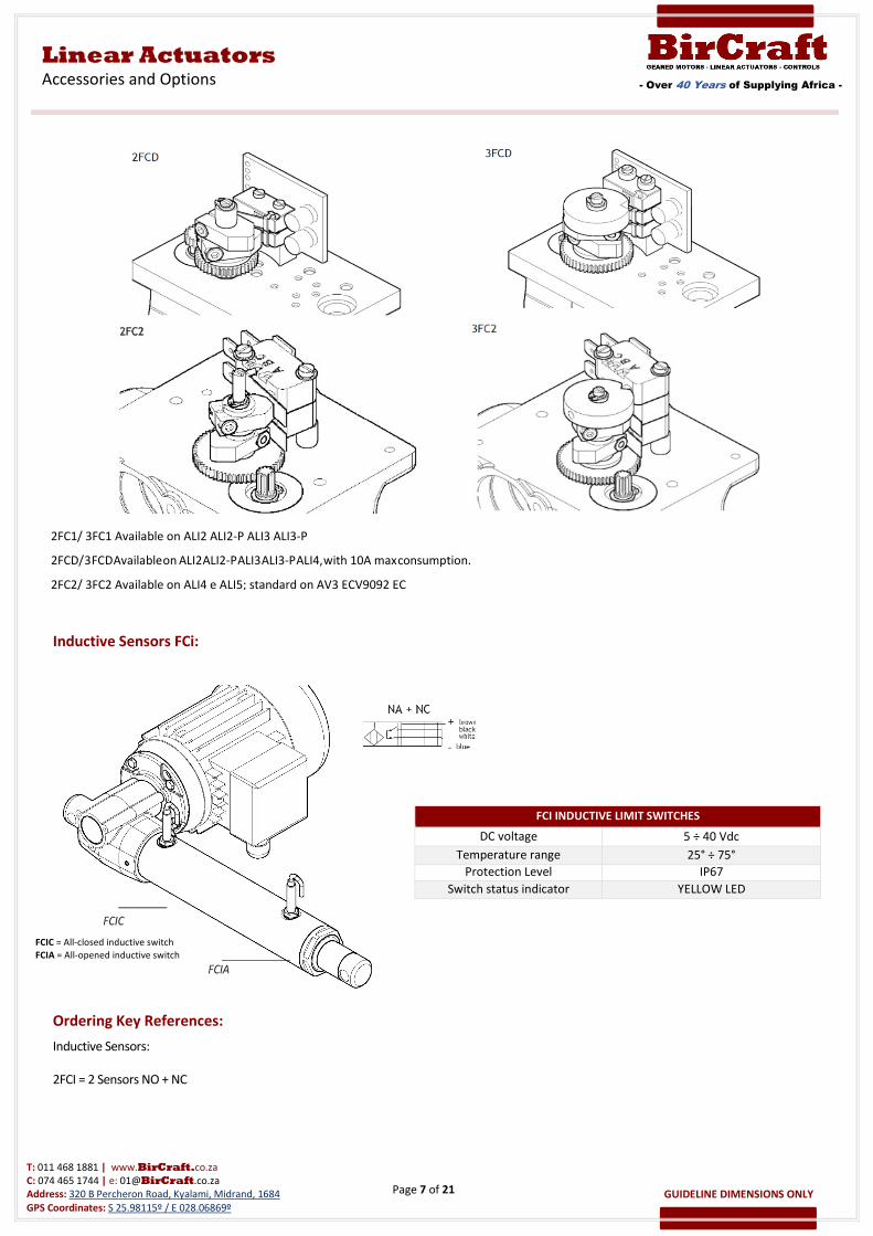
Inductive Sensors FCi:
Ordering Key References:
Inductive Sensors:
2FCI = 2 Sensors NO + NC
FCI INDUCTIVE LIMIT SWITCHES
DC voltage 5 ÷ 40 Vdc
Temperature range 25° ÷ 75°
Protection Level IP67
Switch status indicator YELLOW LED
FCIC = All-closed inductive switch
FCIA = All-opened inductive switch
2FC1/ 3FC1 Available on ALI2 ALI2-P ALI3 ALI3-P
2FCD/ 3 FCD Available on ALI2 ALI2-P ALI3 ALI3-P ALI4, with 10A max consumption.
2FC2/ 3FC2 Available on ALI4 e ALI5; standard on AV3 ECV9092 EC
Page 8 of 21
- Over 40 Years of Supplying Africa -
Linear Actuators
Accessories and Options
T: 011 468 1881 | www.BirCraft.co.za
C: 074 465 1744 | e: [email protected]
Address: 320 B Percheron Road, Kyalami, Midrand, 1684
GPS Coordinates: S 25.98115º / E 028.06869º
GUIDELINE DIMENSIONS ONLY
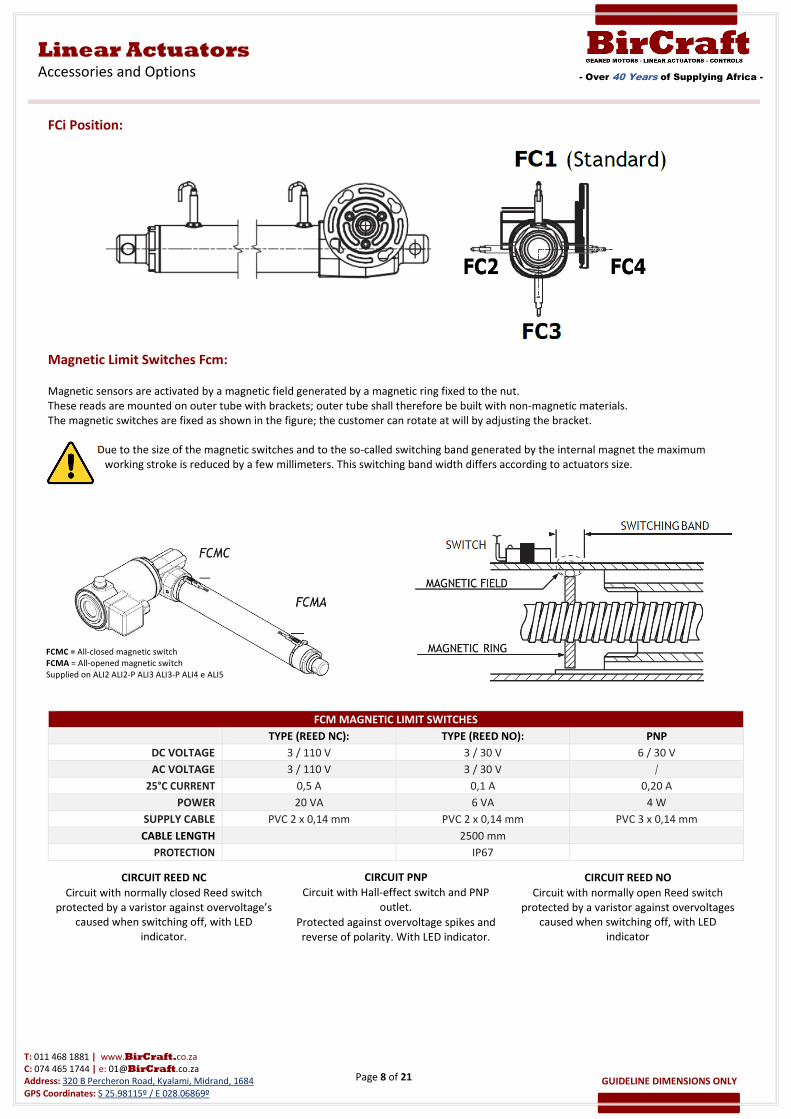
FCi Position:
Magnetic Limit Switches Fcm:
Magnetic sensors are activated by a magnetic field generated by a magnetic ring fixed to the nut.
These reads are mounted on outer tube with brackets; outer tube shall therefore be built with non-magnetic materials.
The magnetic switches are fixed as shown in the figure; the customer can rotate at will by adjusting the bracket.
Due to the size of the magnetic switches and to the so-called switching band generated by the internal magnet the maximum
working stroke is reduced by a few millimeters. This switching band width differs according to actuators size.
FCM MAGNETIC LIMIT SWITCHES
TYPE (REED NC): TYPE (REED NO): PNP
DC VOLTAGE 3 / 110 V 3 / 30 V 6 / 30 V
AC VOLTAGE 3 / 110 V 3 / 30 V /
25°C CURRENT 0,5 A 0,1 A 0,20 A
POWER 20 VA 6 VA 4 W
SUPPLY CABLE PVC 2 x 0,14 mm PVC 2 x 0,14 mm PVC 3 x 0,14 mm
CABLE LENGTH 2500 mm
PROTECTION IP67
CIRCUIT REED NC
Circuit with normally closed Reed switch
protected by a varistor against overvoltage’s
caused when switching off, with LED
indicator.
CIRCUIT PNP
Circuit with Hall-effect switch and PNP
outlet.
Protected against overvoltage spikes and
reverse of polarity. With LED indicator.
CIRCUIT REED NO
Circuit with normally open Reed switch
protected by a varistor against overvoltages
caused when switching off, with LED
indicator
FCMC = All-closed magnetic switch
FCMA = All-opened magnetic switch
Supplied on ALI2 ALI2-P ALI3 ALI3-P ALI4 e ALI5
Page 9 of 21
- Over 40 Years of Supplying Africa -
Linear Actuators
Accessories and Options
T: 011 468 1881 | www.BirCraft.co.za
C: 074 465 1744 | e: [email protected]
Address: 320 B Percheron Road, Kyalami, Midrand, 1684
GPS Coordinates: S 25.98115º / E 028.06869º
GUIDELINE DIMENSIONS ONLY
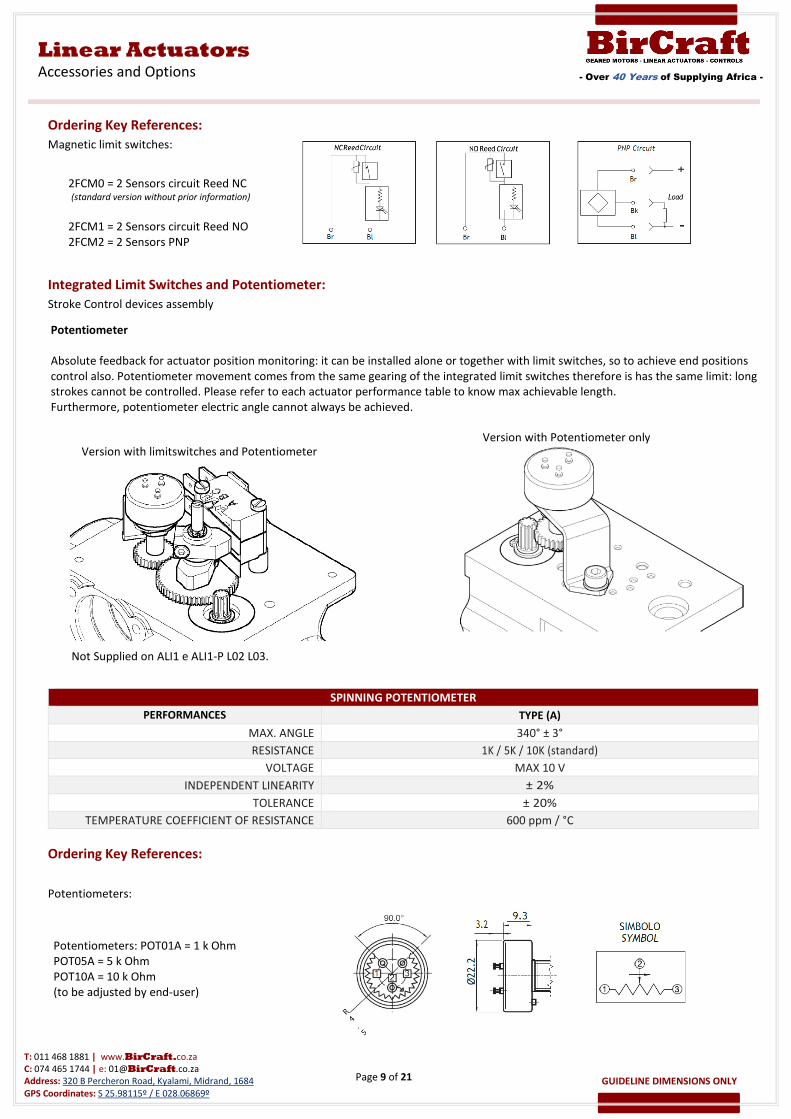
Ordering Key References:
Magnetic limit switches:
Integrated Limit Switches and Potentiometer:
Stroke Control devices assembly
SPINNING POTENTIOMETER
PERFORMANCES TYPE (A)
MAX. ANGLE 340° ± 3°
RESISTANCE 1K / 5K / 10K (standard)
VOLTAGE MAX 10 V
INDEPENDENT LINEARITY ± 2%
TOLERANCE ± 20%
TEMPERATURE COEFFICIENT OF RESISTANCE 600 ppm / °C
Ordering Key References:
Potentiometers:
Version with Potentiometer only
Version with limitswitches and Potentiometer
2FCM0 = 2 Sensors circuit Reed NC (standard version without prior information)
2FCM1 = 2 Sensors circuit Reed NO
2FCM2 = 2 Sensors PNP
Potentiometer
Absolute feedback for actuator position monitoring: it can be installed alone or together with limit switches, so to achieve end positions
control also. Potentiometer movement comes from the same gearing of the integrated limit switches therefore is has the same limit: long
strokes cannot be controlled. Please refer to each actuator performance table to know max achievable length.
Furthermore, potentiometer electric angle cannot always be achieved.
Not Supplied on ALI1 e ALI1-P L02 L03.
Potentiometers: POT01A = 1 k Ohm
POT05A = 5 k Ohm
POT10A = 10 k Ohm
(to be adjusted by end-user)
Page 10 of 21
- Over 40 Years of Supplying Africa -
Linear Actuators
Accessories and Options
T: 011 468 1881 | www.BirCraft.co.za
C: 074 465 1744 | e: [email protected]
Address: 320 B Percheron Road, Kyalami, Midrand, 1684
GPS Coordinates: S 25.98115º / E 028.06869º
GUIDELINE DIMENSIONS ONLY
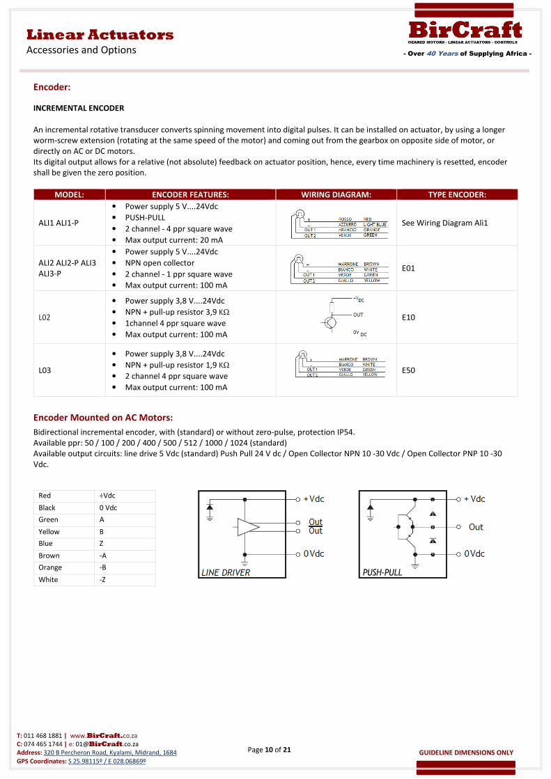
Encoder:
INCREMENTAL ENCODER
An incremental rotative transducer converts spinning movement into digital pulses. It can be installed on actuator, by using a longer
worm-screw extension (rotating at the same speed of the motor) and coming out from the gearbox on opposite side of motor, or
directly on AC or DC motors.
Its digital output allows for a relative (not absolute) feedback on actuator position, hence, every time machinery is resetted, encoder
shall be given the zero position.
Encoder Mounted on AC Motors:
Bidirectional incremental encoder, with (standard) or without zero-pulse, protection IP54.
Available ppr: 50 / 100 / 200 / 400 / 500 / 512 / 1000 / 1024 (standard)
Available output circuits: line drive 5 Vdc (standard) Push Pull 24 V dc / Open Collector NPN 10 -30 Vdc / Open Collector PNP 10 -30
Vdc.
MODEL: ENCODER FEATURES: WIRING DIAGRAM: TYPE ENCODER:
ALI1 ALI1-P
• Power supply 5 V....24Vdc
• PUSH-PULL
• 2 channel - 4 ppr square wave
• Max output current: 20 mA
See Wiring Diagram Ali1
ALI2 ALI2-P ALI3
ALI3-P
• Power supply 5 V....24Vdc
• NPN open collector
• 2 channel - 1 ppr square wave
• Max output current: 100 mA
E01
L02
• Power supply 3,8 V....24Vdc
• NPN + pull-up resistor 3,9 KΩ
• 1channel 4 ppr square wave
• Max output current: 100 mA
E10
L03
• Power supply 3,8 V....24Vdc
• NPN + pull-up resistor 1,9 KΩ
• 2 channel 4 ppr square wave
• Max output current: 100 mA
E50
Red ÷Vdc
Black 0 Vdc
Green A
Yellow B
Blue Z
Brown -A
Orange -B
White -Z
Page 11 of 21
- Over 40 Years of Supplying Africa -
Linear Actuators
Accessories and Options
T: 011 468 1881 | www.BirCraft.co.za
C: 074 465 1744 | e: [email protected]
Address: 320 B Percheron Road, Kyalami, Midrand, 1684
GPS Coordinates: S 25.98115º / E 028.06869º
GUIDELINE DIMENSIONS ONLY
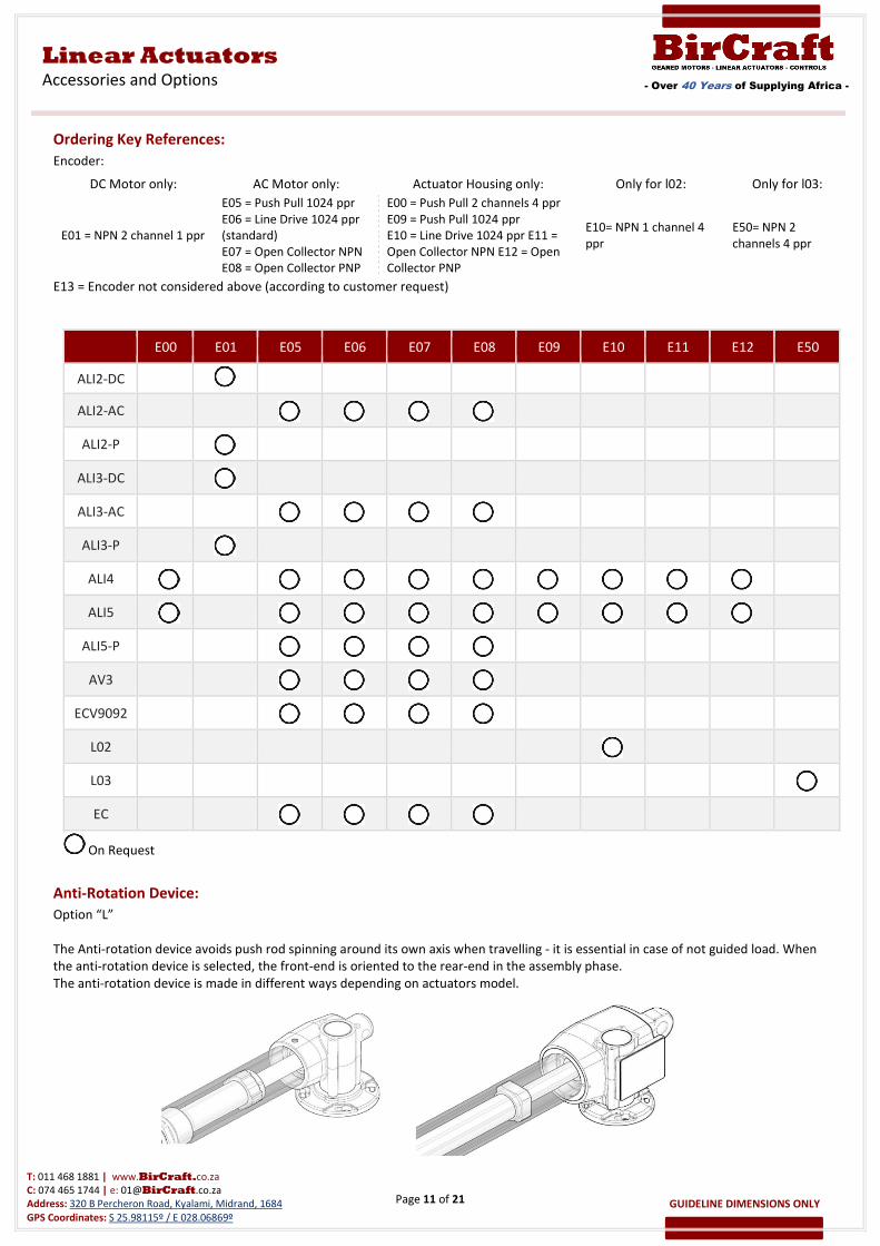
Ordering Key References:
Encoder:
DC Motor only: AC Motor only: Actuator Housing only: Only for l02: Only for l03:
E01 = NPN 2 channel 1 ppr
E05 = Push Pull 1024 ppr
E06 = Line Drive 1024 ppr
(standard)
E07 = Open Collector NPN
E08 = Open Collector PNP
E00 = Push Pull 2 channels 4 ppr
E09 = Push Pull 1024 ppr
E10 = Line Drive 1024 ppr E11 =
Open Collector NPN E12 = Open
Collector PNP
E10= NPN 1 channel 4
ppr
E50= NPN 2
channels 4 ppr
E13 = Encoder not considered above (according to customer request)
E00 E01 E05 E06 E07 E08 E09 E10 E11 E12 E50
ALI2-DC
ALI2-AC
ALI2-P
ALI3-DC
ALI3-AC
ALI3-P
ALI4
ALI5
ALI5-P
AV3
ECV9092
L02
L03
EC
Anti-Rotation Device:
Option “L”
The Anti-rotation device avoids push rod spinning around its own axis when travelling - it is essential in case of not guided load. When
the anti-rotation device is selected, the front-end is oriented to the rear-end in the assembly phase.
The anti-rotation device is made in different ways depending on actuators model.
On Request
Page 12 of 21
- Over 40 Years of Supplying Africa -
Linear Actuators
Accessories and Options
T: 011 468 1881 | www.BirCraft.co.za
C: 074 465 1744 | e: [email protected]
Address: 320 B Percheron Road, Kyalami, Midrand, 1684
GPS Coordinates: S 25.98115º / E 028.06869º
GUIDELINE DIMENSIONS ONLY
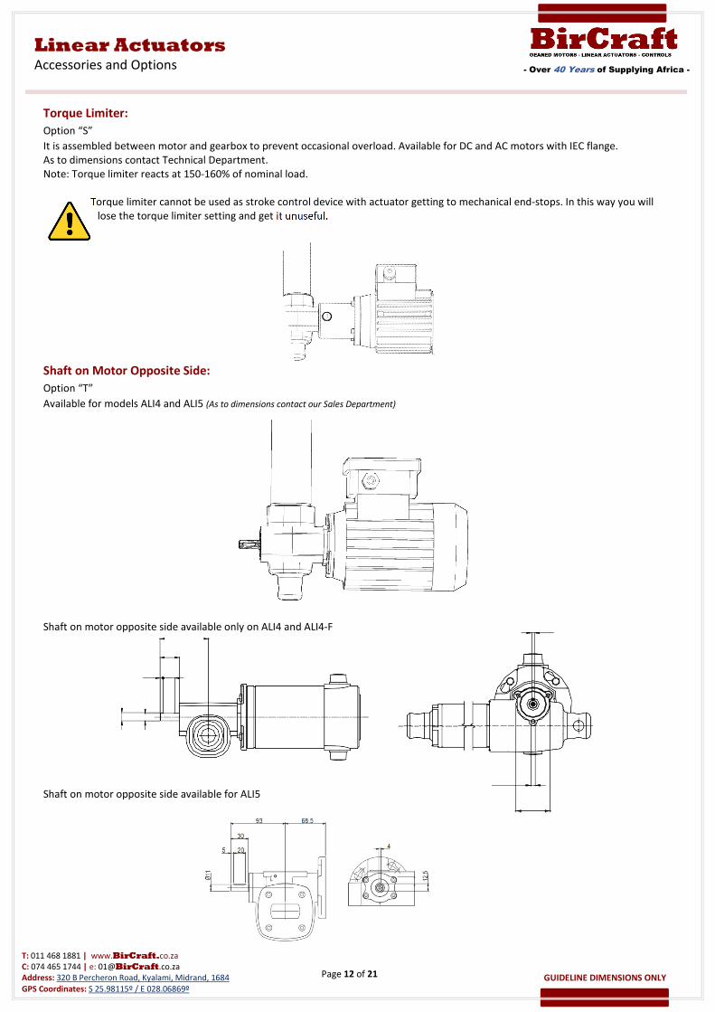
Torque Limiter:
Option “S”
It is assembled between motor and gearbox to prevent occasional overload. Available for DC and AC motors with IEC flange.
As to dimensions contact Technical Department.
Note: Torque limiter reacts at 150-160% of nominal load.
Torque limiter cannot be used as stroke control device with actuator getting to mechanical end-stops. In this way you will
lose the torque limiter setting and get it unuseful.
Shaft on Motor Opposite Side:
Option “T”
Available for models ALI4 and ALI5 (As to dimensions contact our Sales Department)
Shaft on motor opposite side available only on ALI4 and ALI4-F
Shaft on motor opposite side available for ALI5
Page 13 of 21
- Over 40 Years of Supplying Africa -
Linear Actuators
Accessories and Options
T: 011 468 1881 | www.BirCraft.co.za
C: 074 465 1744 | e: [email protected]
Address: 320 B Percheron Road, Kyalami, Midrand, 1684
GPS Coordinates: S 25.98115º / E 028.06869º
GUIDELINE DIMENSIONS ONLY
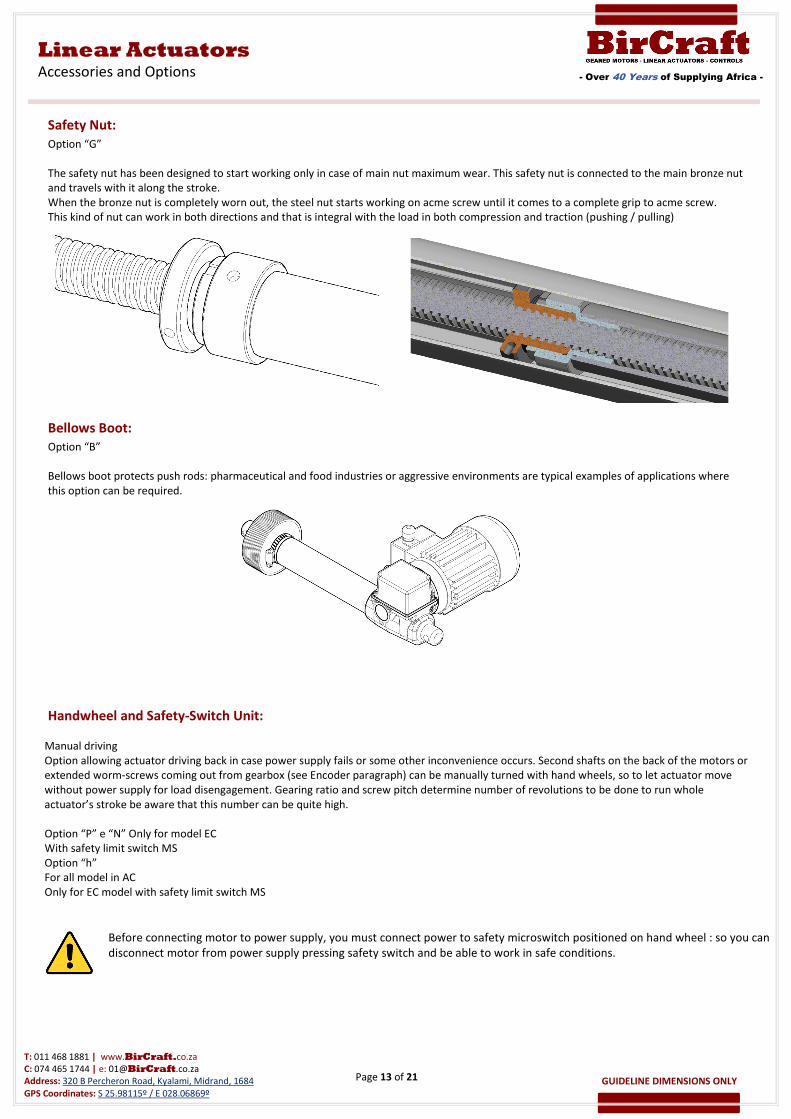
Safety Nut:
Option “G”
The safety nut has been designed to start working only in case of main nut maximum wear. This safety nut is connected to the main bronze nut
and travels with it along the stroke.
When the bronze nut is completely worn out, the steel nut starts working on acme screw until it comes to a complete grip to acme screw.
This kind of nut can work in both directions and that is integral with the load in both compression and traction (pushing / pulling)
Bellows Boot:
Option “B”
Bellows boot protects push rods: pharmaceutical and food industries or aggressive environments are typical examples of applications where
this option can be required.
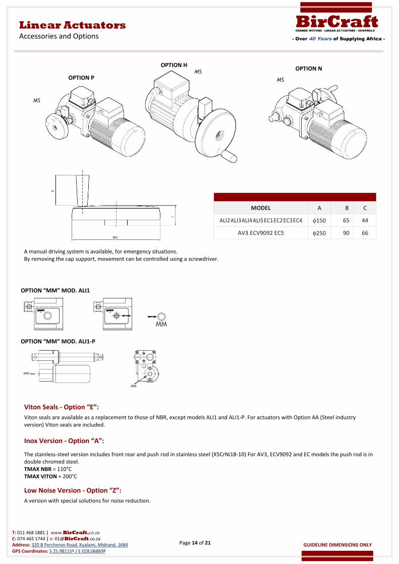
Handwheel and Safety-Switch Unit:
Manual driving
Option allowing actuator driving back in case power supply fails or some other inconvenience occurs. Second shafts on the back of the motors or
extended worm-screws coming out from gearbox (see Encoder paragraph) can be manually turned with hand wheels, so to let actuator move
without power supply for load disengagement. Gearing ratio and screw pitch determine number of revolutions to be done to run whole
actuator’s stroke be aware that this number can be quite high.
Option “P” e “N” Only for model EC
With safety limit switch MS
Option “h”
For all model in AC
Only for EC model with safety limit switch MS
Before connecting motor to power supply, you must connect power to safety microswitch positioned on hand wheel : so you can
disconnect motor from power supply pressing safety switch and be able to work in safe conditions.
Page 14 of 21
- Over 40 Years of Supplying Africa -
Linear Actuators
Accessories and Options
T: 011 468 1881 | www.BirCraft.co.za
C: 074 465 1744 | e: [email protected]
Address: 320 B Percheron Road, Kyalami, Midrand, 1684
GPS Coordinates: S 25.98115º / E 028.06869º
GUIDELINE DIMENSIONS ONLY
MODEL A B C
ALI2 ALI3 ALI4 ALI5 EC1 EC2 EC3 EC4 φ150 65 44
AV3 ECV9092 EC5 φ250 90 66
Viton Seals - Option “E”:
Viton seals are available as a replacement to those of NBR, except models ALI1 and ALI1-P. For actuators with Option AA (Steel industry
version) Viton seals are included.
Inox Version - Option “A”:
The stainless-steel version includes front rear and push rod in stainless steel (X5CrNi18-10) For AV3, ECV9092 and EC models the push rod is in
double chromed steel.
TMAX NBR = 110°C
TMAX VITON = 200°C
Low Noise Version - Option “Z”:
A version with special solutions for noise reduction.
A manual driving system is available, for emergency situations.
By removing the cap support, movement can be controlled using a screwdriver.
OPTION “MM” MOD. ALI1
OPTION “MM” MOD. ALI1-P
OPTION P
OPTION H
OPTION N

Page 15 of 21
- Over 40 Years of Supplying Africa -
Linear Actuators
Accessories and Options
T: 011 468 1881 | www.BirCraft.co.za
C: 074 465 1744 | e: [email protected]
Address: 320 B Percheron Road, Kyalami, Midrand, 1684
GPS Coordinates: S 25.98115º / E 028.06869º
GUIDELINE DIMENSIONS ONLY
Protective Painting – Option “FX”:
Anti-Corrosion coating used on all metals and many other materials also against aggressive agents such extreme sea water, industrial fumes,
acid rain, etc.
It also has excellent resistance to impact and abrasion.
Protective Painting – Option “FXC”:
Cataphoresis is an electro deposition of paint in immersion with current continuous electrical worker. The deposited film confers to the pieces
ones elevated characteristic anticorrosive, extending in the time the conservation also of all the parts that are not available with a traditional
system to spray.
Steel Industry Version – Option “AA”:
Steel works includes:
Larger limit switches box.
Brass gears and cams.
Metal connectors.
Viton seals.
Mechanical limiter with warning sensor.
Handwheel for manual driving (standard pos.N; optional P and H).
Front end with shock absorber.
Electronic Devices:
Electronic Control Cards
CODE DATA APPLICATION PICTURE
PF.0014
Driver for 1 actuator with 24 Vdc motor
Power supply: 230 V - max 4A (for 24 Vdc
motors)
Amperage limitation
Sound or light signal of movement
All Ø61,5 and Ø40 motors
may work with amperage
limitation
PF.0015 Infrared remote control - 2 buttons for
PF0014 Accessory for PF0014
PF.0050
Driver for 2 actuators with 12 Vdc motor
Power supply: 12 Vdc +/- 10% 4-28A (for 12
Vdc motors)
Stroke limits control normally closed
Amperage limitation
Radio remote control - 4 buttons
I MAX = 28A
All 12V motors Ø61,5 and
Ø40 motors
PF.0100
Driver for 1-2 actuators with 12-24 Vdc
motor 15A Power supply 10. 48 Vdc
Stop by limit switches or programmable
current threshold Acceleration and
deceleration ramp (PWM)
Parameters can be set by external
interface, the interface is provided only in
the first delivery
Optional:
CAN BUS
Synchronization 2 actuators Radio Control
Dim. 86X72X50 I MAX =
15A
All 24V Ø61,5 and Ø40
motors
12-24V
Page 16 of 21
- Over 40 Years of Supplying Africa -
Linear Actuators
Accessories and Options
T: 011 468 1881 | www.BirCraft.co.za
C: 074 465 1744 | e: [email protected]
Address: 320 B Percheron Road, Kyalami, Midrand, 1684
GPS Coordinates: S 25.98115º / E 028.06869º
GUIDELINE DIMENSIONS ONLY
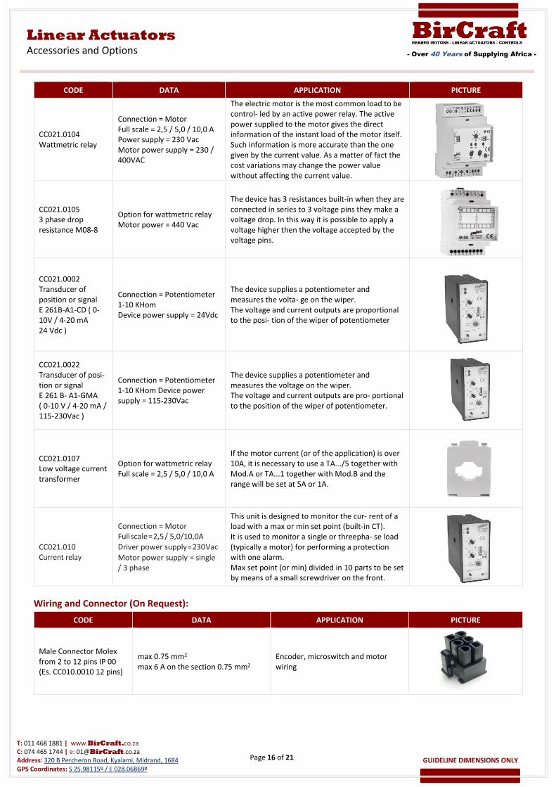
CODE DATA APPLICATION PICTURE
CC021.0104
Wattmetric relay
Connection = Motor
Full scale = 2,5 / 5,0 / 10,0 A
Power supply = 230 Vac
Motor power supply = 230 /
400VAC
The electric motor is the most common load to be
control- led by an active power relay. The active
power supplied to the motor gives the direct
information of the instant load of the motor itself.
Such information is more accurate than the one
given by the current value. As a matter of fact the
cost variations may change the power value
without affecting the current value.
CC021.0105
3 phase drop
resistance M08-8
Option for wattmetric relay
Motor power = 440 Vac
The device has 3 resistances built-in when they are
connected in series to 3 voltage pins they make a
voltage drop. In this way it is possible to apply a
voltage higher then the voltage accepted by the
voltage pins.
CC021.0002
Transducer of
position or signal
E 261B-A1-CD ( 0-
10V / 4-20 mA
24 Vdc )
Connection = Potentiometer
1-10 KHom
Device power supply = 24Vdc
The device supplies a potentiometer and
measures the volta- ge on the wiper.
The voltage and current outputs are proportional
to the posi- tion of the wiper of potentiometer
CC021.0022
Transducer of posi-
tion or signal
E 261 B- A1-GMA
( 0-10 V / 4-20 mA /
115-230Vac )
Connection = Potentiometer
1-10 KHom Device power
supply = 115-230Vac
The device supplies a potentiometer and
measures the voltage on the wiper.
The voltage and current outputs are pro- portional
to the position of the wiper of potentiometer.
CC021.0107
Low voltage current
transformer
Option for wattmetric relay
Full scale = 2,5 / 5,0 / 10,0 A
If the motor current (or of the application) is over
10A, it is necessary to use a TA.../5 together with
Mod.A or TA...1 together with Mod.B and the
range will be set at 5A or 1A.
CC021.010
Current relay
Connection = Motor
Full scale = 2,5 / 5,0/10,0A
Driver power supply = 230 Vac
Motor power supply = single
/ 3 phase
This unit is designed to monitor the cur- rent of a
load with a max or min set point (built-in CT).
It is used to monitor a single or threepha- se load
(typically a motor) for performing a protection
with one alarm.
Max set point (or min) divided in 10 parts to be set
by means of a small screwdriver on the front.
Wiring and Connector (On Request):
CODE DATA APPLICATION PICTURE
Male Connector Molex
from 2 to 12 pins IP 00
(Es. CC010.0010 12 pins)
max 0.75 mm2
max 6 A on the section 0.75 mm2
Encoder, microswitch and motor
wiring
Page 17 of 21
- Over 40 Years of Supplying Africa -
Linear Actuators
Accessories and Options
T: 011 468 1881 | www.BirCraft.co.za
C: 074 465 1744 | e: [email protected]
Address: 320 B Percheron Road, Kyalami, Midrand, 1684
GPS Coordinates: S 25.98115º / E 028.06869º
GUIDELINE DIMENSIONS ONLY
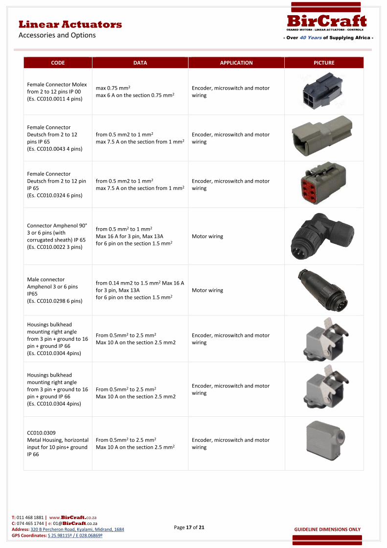
CODE DATA APPLICATION PICTURE
Female Connector Molex
from 2 to 12 pins IP 00
(Es. CC010.0011 4 pins)
max 0.75 mm2
max 6 A on the section 0.75 mm2
Encoder, microswitch and motor
wiring
Female Connector
Deutsch from 2 to 12
pins IP 65
(Es. CC010.0043 4 pins)
from 0.5 mm2 to 1 mm2
max 7.5 A on the section from 1 mm2
Encoder, microswitch and motor
wiring
Female Connector
Deutsch from 2 to 12 pin
IP 65
(Es. CC010.0324 6 pins)
from 0.5 mm2 to 1 mm2
max 7.5 A on the section from 1 mm2
Encoder, microswitch and motor
wiring
Connector Amphenol 90°
3 or 6 pins (with
corrugated sheath) IP 65
(Es. CC010.0022 3 pins)
from 0.5 mm2 to 1 mm2
Max 16 A for 3 pin, Max 13A
for 6 pin on the section 1.5 mm2
Motor wiring
Male connector
Amphenol 3 or 6 pins
IP65
(Es. CC010.0298 6 pins)
from 0.14 mm2 to 1.5 mm2 Max 16 A
for 3 pin, Max 13A
for 6 pin on the section 1.5 mm2
Motor wiring
Housings bulkhead
mounting right angle
from 3 pin + ground to 16
pin + ground IP 66
(Es. CC010.0304 4pins)
From 0.5mm2 to 2.5 mm2
Max 10 A on the section 2.5 mm2
Encoder, microswitch and motor
wiring
Housings bulkhead
mounting right angle
from 3 pin + ground to 16
pin + ground IP 66
(Es. CC010.0304 4pins)
From 0.5mm2 to 2.5 mm2
Max 10 A on the section 2.5 mm2
Encoder, microswitch and motor
wiring
CC010.0309
Metal Housing, horizontal
input for 10 pins+ ground
IP 66
From 0.5mm2 to 2.5 mm2
Max 10 A on the section 2.5 mm2
Encoder, microswitch and motor
wiring
Page 18 of 21
- Over 40 Years of Supplying Africa -
Linear Actuators
Accessories and Options
T: 011 468 1881 | www.BirCraft.co.za
C: 074 465 1744 | e: [email protected]
Address: 320 B Percheron Road, Kyalami, Midrand, 1684
GPS Coordinates: S 25.98115º / E 028.06869º
GUIDELINE DIMENSIONS ONLY
CODE DATA APPLICATION PICTURE
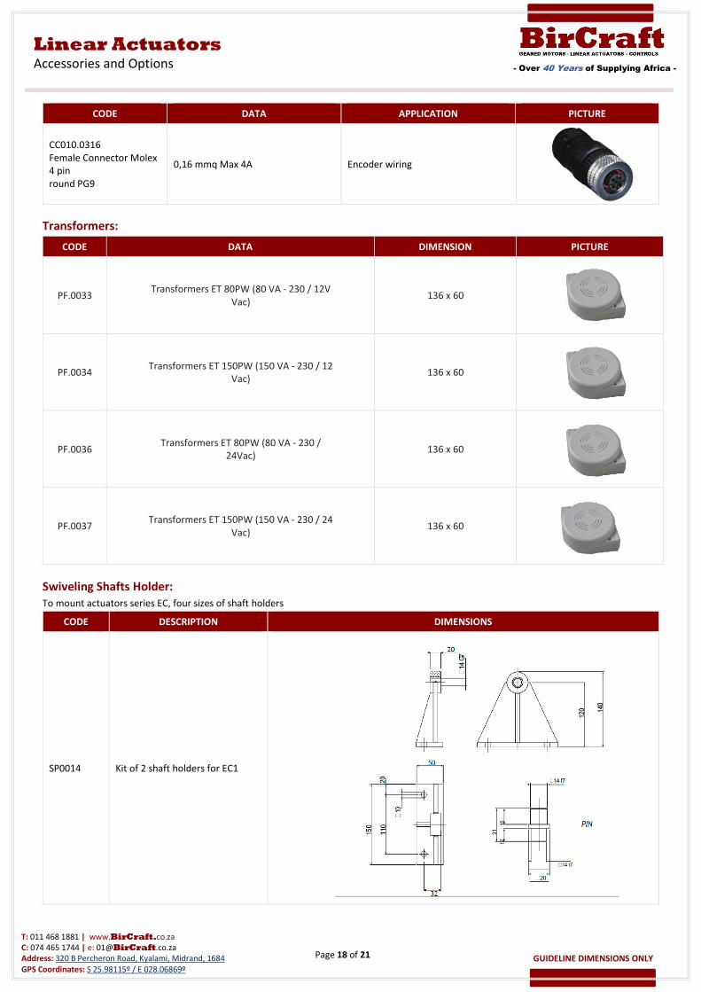
CC010.0316
Female Connector Molex
4 pin
round PG9
0,16 mmq Max 4A Encoder wiring
Transformers:
CODE DATA DIMENSION PICTURE
PF.0033 Transformers ET 80PW (80 VA - 230 / 12V
Vac) 136 x 60
PF.0034 Transformers ET 150PW (150 VA - 230 / 12
Vac) 136 x 60
PF.0036 Transformers ET 80PW (80 VA - 230 /
24Vac) 136 x 60
PF.0037 Transformers ET 150PW (150 VA - 230 / 24
Vac) 136 x 60
Swiveling Shafts Holder:
To mount actuators series EC, four sizes of shaft holders
CODE DESCRIPTION DIMENSIONS
SP0014 Kit of 2 shaft holders for EC1
Page 19 of 21
- Over 40 Years of Supplying Africa -
Linear Actuators
Accessories and Options
T: 011 468 1881 | www.BirCraft.co.za
C: 074 465 1744 | e: [email protected]
Address: 320 B Percheron Road, Kyalami, Midrand, 1684
GPS Coordinates: S 25.98115º / E 028.06869º
GUIDELINE DIMENSIONS ONLY
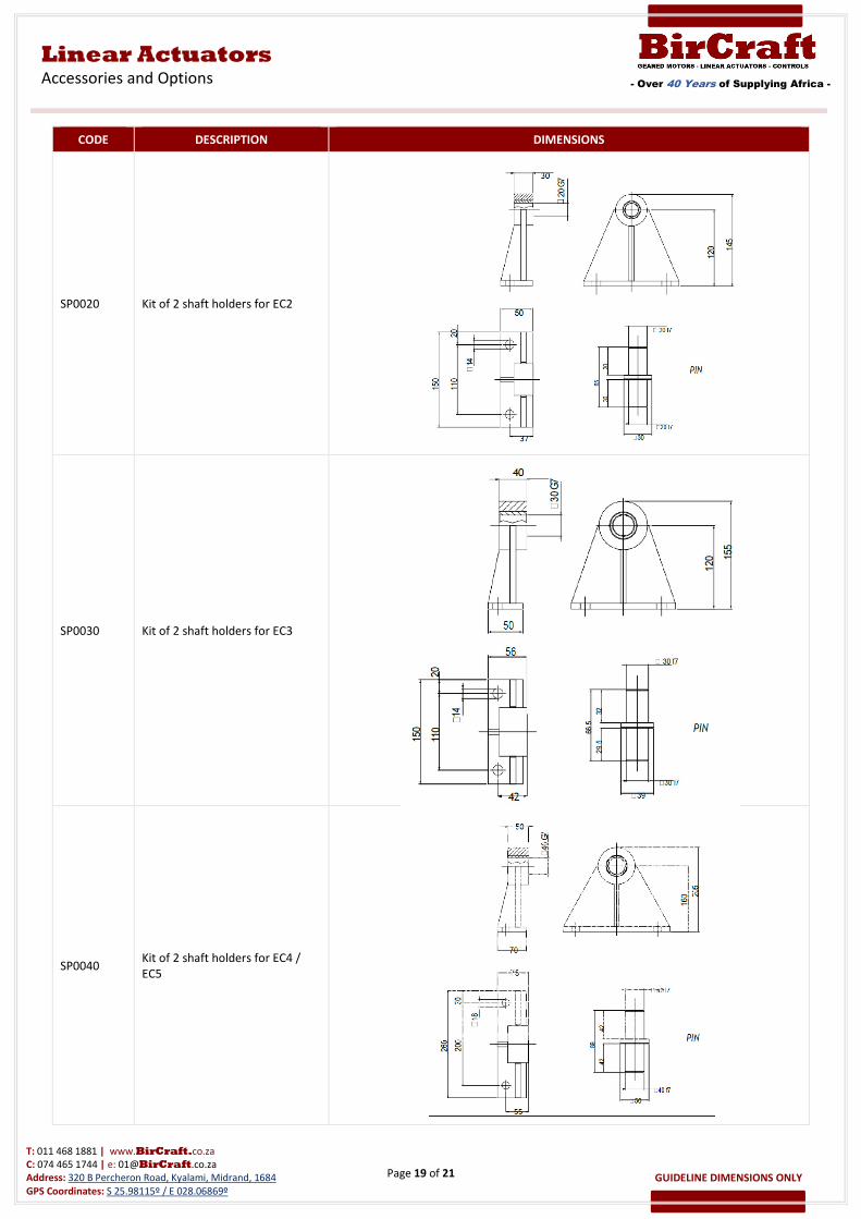
CODE DESCRIPTION DIMENSIONS
SP0020 Kit of 2 shaft holders for EC2
SP0030 Kit of 2 shaft holders for EC3
SP0040 Kit of 2 shaft holders for EC4 /
EC5
TEST
TEST TEST TEST TEST TEST TEST TEST TEST TEST TEST TEST TEST TEST TEST TEST TEST
TEST TEST TEST TEST TEST TEST TEST TEST TEST TEST TEST TEST TEST TEST TEST TEST
TEST TEST TEST TEST TEST TEST TEST TEST TEST TEST TEST TEST TEST TEST TEST TEST
TEST TEST TEST TEST TEST TEST TEST TEST TEST TEST TEST TEST TEST TEST TEST TEST
TEST TEST TEST TEST TEST TEST TEST TEST TEST TEST TEST TEST TEST TEST TEST TEST
TEST TEST TEST TEST TEST TEST TEST TEST TEST TEST TEST TEST TEST TEST TEST TEST
TEST TEST TEST TEST TEST TEST TEST TEST TEST TEST TEST TEST TEST TEST TEST TEST
TEST TEST TEST TEST TEST TEST TEST TEST TEST TEST TEST TEST TEST TEST TEST TEST
TEST TEST TEST TEST TEST TEST TEST TEST TEST TEST TEST TEST TEST TEST TEST TEST
TEST TEST TEST TEST TEST TEST TEST TEST TEST TEST TEST TEST TEST TEST TEST TEST
TEST TEST TEST TEST TEST TEST TEST TEST TEST TEST TEST TEST TEST TEST TEST TEST
TEST TEST TEST TEST TEST TEST TEST TEST TEST TEST TEST TEST TEST TEST TEST TEST
TEST TEST TEST TEST TEST TEST TEST TEST TEST TEST TEST TEST TEST TEST TEST TEST
TEST TEST TEST TEST TEST TEST TEST TEST TEST TEST TEST TEST
Page 20 of 21
- Over 40 Years of Supplying Africa -
Linear Actuators
Accessories and Options
T: 011 468 1881 | www.BirCraft.co.za
C: 074 465 1744 | e: [email protected]
Address: 320 B Percheron Road, Kyalami, Midrand, 1684
GPS Coordinates: S 25.98115º / E 028.06869º
GUIDELINE DIMENSIONS ONLY
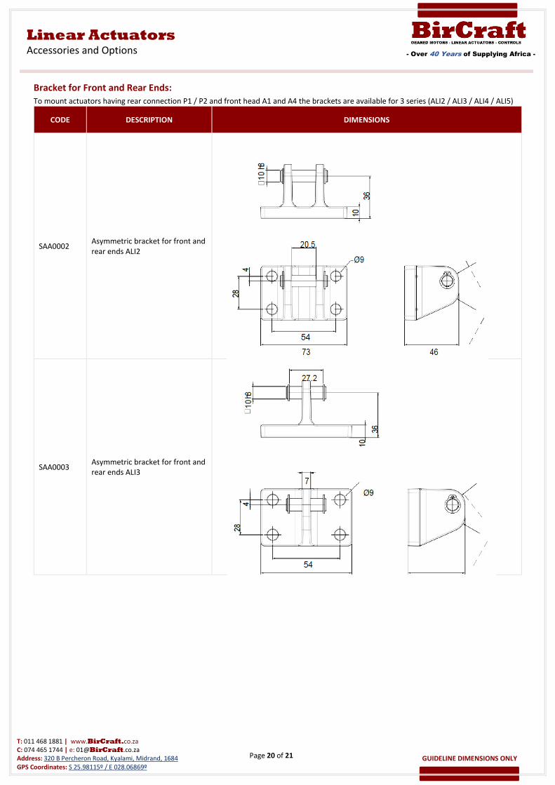
Bracket for Front and Rear Ends:
To mount actuators having rear connection P1 / P2 and front head A1 and A4 the brackets are available for 3 series (ALI2 / ALI3 / ALI4 / ALI5)
CODE DESCRIPTION DIMENSIONS
SAA0002 Asymmetric bracket for front and
rear ends ALI2
SAA0003 Asymmetric bracket for front and
rear ends ALI3
Page 21 of 21
- Over 40 Years of Supplying Africa -
Linear Actuators
Accessories and Options
T: 011 468 1881 | www.BirCraft.co.za
C: 074 465 1744 | e: [email protected]
Address: 320 B Percheron Road, Kyalami, Midrand, 1684
GPS Coordinates: S 25.98115º / E 028.06869º
GUIDELINE DIMENSIONS ONLY
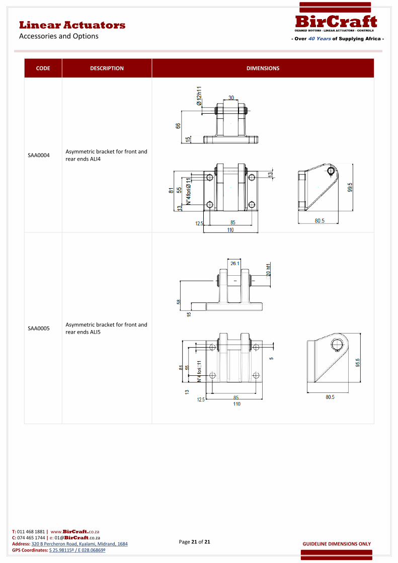
CODE DESCRIPTION DIMENSIONS
SAA0004 Asymmetric bracket for front and
rear ends ALI4
SAA0005 Asymmetric bracket for front and
rear ends ALI5