birnessite polytype systematics and identifi cation by
TRANSCRIPT

American Mineralogist, Volume 92, pages 771–788, 2007
0003-004X/07/0506–771$05.00/DOI: 10.2138/am.2007.2207 771
INTRODUCTION
Birnessite is a hydrous-layered Mn oxide (phyllomanganate). Its layers consist of edge-sharing MnO6 octahedra and these layers are separated from each other by hydrated interlayer cations. These cations compensate for a layer charge defi cit arising either from the presence of vacant layer sites or from the coexistence of heterovalent Mn cations in the octahedral layer. Birnessite interlayers incorporate a single sheet of interlayer H2O molecules, and exhibit a minimum periodicity along the c* axis of ~7 Å (Giovanoli et al. 1970a, 1970b; Burns and Burns 1977; Chukhrov et al. 1978; Post and Veblen 1990). In the following, the term “birnessite” will be used to describe all natural and syn-thetic materials with such a layer structure, whatever the origin of the layer charge, and the actual confi guration and chemical composition of the interlayers.
Over the last few decades, birnessite has attracted a wide
interest for several reasons. First, it is ubiquitous in geological environments in spite of the low abundance of Mn. It is, for example, a major component of Mn nodules, which cover huge areas of the ocean fl oor and the bottom of some lakes. It is also present in soils, sediments, and Mn-rich ore deposits (Burns and Burns 1977, 1978; Chukhrov et al. 1978, 1985; Drits et al. 1985; Golden et al. 1986; Cornell and Giovanoli 1988; Manceau et al. 2000c). It was recently shown that bacteria play a major role in the formation of birnessite in most of these environments (Tebo and He 1999; Tebo et al. 2004; and references therein). Second, this mineral plays an essential role in different ion-exchange and redox processes because of its unique surface charge, and adsorption and redox properties (Manceau and Charlet 1992; Manceau et al. 1992a, 1992b; Paterson et al. 1994; Stone et al. 1994; Tu et al. 1994; Le Goff et al. 1996; Silvester et al. 1997). In particular, birnessite plays a pivotal role in the fate of heavy metals and other pollutants in contaminated water systems and soils (Chao and Theobald 1976; Manceau et al. 1997, 1999, 2000a, 2000b). Despite its low abundance, birnessite controls * E-mail: [email protected]
Birnessite polytype systematics and identifi cation by powder X-ray diffraction
VICTOR A. DRITS,1,2 BRUNO LANSON,1,* AND ANNE-CLAIRE GAILLOT1
1Environmental Geochemistry Group, LGIT—Maison des Géosciences, University of Grenoble—CNRS, 38041 Grenoble Cedex 9, France2Geological Institute, Russian Academy of Sciences, 7 Pyzhevsky Street, 109017 Moscow, Russia
ABSTRACT
The polytypes of birnessite with a periodic stacking along the c* axis of one-, two-, and three-layers are derived in terms of an anion close-packing formalism. Birnessite layers may be stacked so as to build two types of interlayers: P-type in which basal O atoms from adjacent layers coincide in projection along the c* axis, thus forming interlayer prisms; and, O-type in which these O atoms form interlayer octahedra. The polytypes can be categorized into three groups that depend on the type of interlayers: polytypes consisting of homogeneous interlayers of O- or P-type, and polytypes in which both interlayer types alternate. Ideal birnessite layers can be described by a hexagonal unit cell (ah = bh ≈ 2.85 Å and γ = 120°) or by an orthogonal C-centered cell (a = √3 b, bh ≈ 2.85 Å, and γ = 90°); and, hexagonal birnessite polytypes (1H, 2H1, 2H2, 3R1, 3R2, 3H1, and 3H2) have orthogonal analogs (1O, 2O1, 2O2, 1M1, 1M2, 3O1, and 3O2).
X-ray diffraction (XRD) patterns from different polytypes having the same layer symmetry and the same number of layers per unit cell exhibit hkl refl ections at identical 2θ positions. XRD patterns corresponding to such polytypes differ only by their hkl intensity distributions, thus leading to possible ambiguities in polytype identifi cation. In addition, the characteristics of the birnessite XRD patterns depend not only on the layer stacking but also on the presence of vacant layer sites, and on the type, location, and local environment of interlayer cations.
Several structure models are described for birnessite consisting of orthogonal vacancy-free or of hexagonal vacancy-bearing layers. These models differ by their stacking modes and by their interlayer structures, which contain mono-, di-, or trivalent cations. Calculated XRD patterns for these models show that the hkl intensity distributions are determined by the polytype, with limited infl uence of the interlayer structure. Actual structures of phyllomanganates can thus be approximated by ideal-ized models for polytype identifi cation purpose. General rules for this identifi cation are formulated. Finally, the occurrence of the different polytypes among natural and synthetic birnessite described in the literature is considered with special attention given to poorly understood structural and crystal-chemical features.
Keywords: Birnessite, polytype, phyllomanganate, Mn oxide

DRITS ET AL.: IDENTIFICATION OF BIRNESSITE POLYTYPES772
the distribution of some trace elements such as radionuclides, Pt-group elements, and rare-earth elements (Manceau et al. 1999). In addition, birnessite has also attracted special attention because of its potential use as materials for batteries and other industrial applications (Kim et al. 1999).
Third, birnessite can be synthesized under various physico-chemical conditions and from 0 to 1000 °C. Synthetic birnes-site is used to mimic naturally occurring redox and adsorption processes, being considered as analogous to natural varieties. Birnessite can be synthesized by the oxidation of Mn2+ in a highly alkaline medium (Giovanoli et al. 1970a, 1970b; Cornell and Giovanoli 1988; Kim et al. 2000), leading, for example, to the to-potactic transformation of Mn(OH)2 when subjected to the action of different oxidizers. Other methods using MnO4
– as a starting reagent (Herbstein et al. 1971; Ching et al. 1995, 1997a, 1997b; Chen et al. 1996a, 1996b; Ching and Suib 1997; Kim et al. 1999) include mild hydrothermal syntheses (Feng et al. 1995; Chen et al. 1996a, 1996b), sol-gel processes (Bach et al. 1990, 1993; Le Goff et al. 1994; Ching et al. 1995, 1997a; Cho et al. 1999), interactions of KMnO4 with hydrochloric acid, and ion-exchange of the hydrogen form of birnessite to the Na- or K-forms (Tsuji et al. 1992; Leroux et al. 1995), and thermal decomposition of KMnO4 at high temperature (Kim et al. 1999).
These different methods lead to the crystallization of birnes-site having different layer stackings and different interlayer structures, which depend on the chemical nature of interlayer cations, their amounts, distribution, and coordination geometry. In addition, birnessite is, as a rule, fi ne-grained and contains stacking faults and/or consists of interstratifi ed layer types cor-responding to different birnessite polytypes (Drits et al. 1997a, 2002; Silvester et al. 1997; Manceau et al. 2000c, 2002; Lanson et al. 2002a, 2002b). As a result, strikingly different X-ray dif-fraction patterns are obtained from birnessite crystallized under different physico-chemical conditions. As a consequence, there has been a lot of confusion, even in the recent literature, as to the structure of these layer manganates (e.g., Chen et al. 1996b; Kim et al. 1999; Yang and Wang 2001). One diffi culty in the interpretation of the birnessite XRD patterns is that, until recently, even unit-cell parameters reported in the literature were not deter-mined unambiguously. Therefore, determination of the birnessite structure was sometimes limited to a general description of the XRD patterns without any indexing or accurate determination of unit-cell parameters (Feng et al. 1997a, 1997b; Aronson et al. 1999; Ma et al. 1999; Yang and Wang 2001). In some cases index-ing of hkl refl ections was carried out without proper justifi cation (e.g., Le Goff et al. 1994, 1996; Ching et al. 1995; Aronson et al. 1999). Signifi cant progress was achieved recently in the structural characterization of birnessite (Post and Veblen 1990; Kuma et al. 1994; Drits et al. 1997a, 1998, 2002; Manceau et al. 1997, 2000c, 2002; Silvester et al. 1997; Lanson et al. 2000, 2002a, 2002b) and specifi cally in the determination of their unit-cell parameters (Chen et al. 1996a, 1996b; Kim et al. 1999; Lanson et al. 2000, 2002a, 2002b). However, no systematic description of reliable criteria for the identifi cation of birnessite polytypes is available, to our knowledge, in the existing literature.
As for layer silicates (Bailey 1988) the optimal way to estab-lish such criteria is to deduce theoretically all birnessite polytypes taking into account the main crystal-chemical features of their
layers and interlayers, to calculate the corresponding XRD pat-terns and to formulate diffraction criteria for their identifi cation. This paper is devoted to such a systematic approach and describes how birnessite polytypes having the same unit-cell parameters can be identifi ed.
BIRNESSITE POLYTYPE DIVERSITY
Polytype diversity in terms of close-packing formalismThe two-dimensional periodicity of birnessite layers can be
described either by a hexagonal unit cell, with ah = bh ≈ 2.85 Å and γ = 120°, or by an equivalent orthogonal C-centered cell, with a = √3 b, bh ≈ 2.85 Å, and γ = 90°. The orthogonal C-centered cell will be used systematically throughout the current manuscript. The birnessite layer consists of two closely packed anion sheets “sandwiching” Mn cations. The anion close-packing formalism can thus be used to describe the mutual arrangement of birnessite layers. As a fi rst step all possible periodic stackings of birnes-site layers with periodicity along the c axis of 1, 2, and 3 layers will be considered. Non-equivalent crystallographic sites of the layer oxygen atoms (Olayer) will be hereafter described with capital letters A, B, and C, whereas positions of the Mn cations will be described with corresponding a, b, and c letters (Fig. 1). It is systematically assumed that the lower surface of the fi rst birnessite layer is an oxygen sheet in which the the Olayer occupies A sites, that Mn cations fi ll octahedral b positions, and that the upper surface is formed by Olayer in C sites. Such a layer can be symbolically represented as AbC. In the simulation of idealized polytypes, it is assumed that the Olayer in the lower sheet of the next birnessite layer in a stack can occupy A, B or C positions. If these Olayer are located in C sites, Olayer from adjacent layers defi ne interlayer prisms. This type of interlayer will be referred to as a P-type interlayer and denoted with an equal sign (=). If they are located in A or B sites, Olayer from adjacent layers defi ne interlayer octahedra. These interlayers are referred to as O-type and denoted with a dash sign (–) to distinguish them from the P-type interlayers. Using the above notions, a one-layer polytype having O-type interlayer (Fig. 1a) can be represented as:
AbC – AbC... 1H
Systematic consideration of possible two-layer polytypes leads to two independent hexagonal polytypes having homoge-neous interlayers (Figs. 1b and 1c):
AbC = CbA = AbC... 2H1
AbC – AcB – AbC... 2H2
With this notation, the fi rst digit indicates the number of layers per unit cell, the letter corresponds to the layer symmetry (H, R, and M standing for hexagonal, rhombohedral, and monoclinic, respectively), and the fi nal numerical subscript determines the polytype. In 2H1 and 2H2 polytypes, adjacent layers are rotated with respect to each other by 180° around the axis parallel to the c axis and passing either through Mn atoms of adjacent layers (2H1) or through the “lower” Olayer (A sites – 2H2). In 1H and 2H1, the Mnlayer octahedral sites overlap in projection on the a-b plane, whereas these sites are distributed more homogeneously in 2H2.
Analysis of three-layer polytypes leads to two independent modifi cations with rhombohedral symmetry (3R). These two

DRITS ET AL.: IDENTIFICATION OF BIRNESSITE POLYTYPES 773
polytypes differ from each other by their interlayer structures (Figs. 2a and 2b):
AbC = CaB = BcA = AbC... 3R1
AbC – BcA – CaB – AbC... 3R2
Two additional three-layer polytypes having O-type inter-layers and hexagonal symmetry may also be derived (Figs. 2c and 2d):
AbC – AcB – AcB – AbC... 3H1
AbC – AcB – CaB – AbC... 3H2
In terms of the C-centered orthogonal unit cell, successive layers in 3R1 and 3R2 polytypes are shifted by –a/3 and +a/3, respectively. As in 2H2 polytype, successive layers in 3H1 and 3H2 polytypes are not related by the same interlayer displacement. In addition, layers from different layer pairs are related to each other by different elements of symmetry in 3H1 and 3H2 polytypes. For example, layers in the fi rst layer pair of the 3H1 polytype are related by a 180° rotation along the c axis passing through A sites, whereas they are superimposed in the second pair (Fig. 2c). In the latter layer pairs, Mn octahedral sites overlap in projection on the a-b plane, whereas in 3R1, 3R2, and 3H2 polytypes, layer Mn cations are distributed homogeneously among all possible sites (Figs. 2a, 2b, and 2d).
Heterogeneity arising from the coexistence of O- and P-
type interlayers in a given birnessite polytype is unlikely to be energetically favorable. Polytypes with alternating O- and P-type interlayers were thus excluded from the current study. However, transformation from one polytype to the other likely often occurs through layer translations. Such displacements occur, for example, as a result of cation exchange or during hydration-dehydration processes. Therefore, among birnessite polytypes some unusual modifi cations can be formed from one-layer polytype by shifting the layers. For example, a two-layer structure AbC – BcA = AbC with both interlayer types can be obtained if successive layers are shifted alternately by +a/3 and –a/3 along the a axis of the C-centered unit cell.
The above idealized birnessite polytypes are similar to those of oxides with the general formula AxMO2 (Delmas et al. 1980). These authors deduced four polytypes, T1, P2, P3, and O3, which correspond to 1H1, 2H2, 3R1, and 3R2 modifi cations in the present no-menclature. Birnessite polytypes are also similar to those of natural and synthetic layer double hydroxides (R2+
1–xRx3+)(OH)2(CO3,SO4)x/2
(Drits 1987; Bookin and Drits 1993; Drits and Bookin 2001) and to those of other natural and synthetic layered compounds (Bailey 1980).
Layer symmetry and polytype diversity
Structural characterization of birnessite shows layers with either hexagonal or pseudo-hexagonal symmetry. Birnessite
ac
a
b
Aa) b C
C
b
A
A b C
ac*
Ab) b C
C
b
A
A b C
a
b
ac
Ac) B c
C
b
A
A b C
a
b
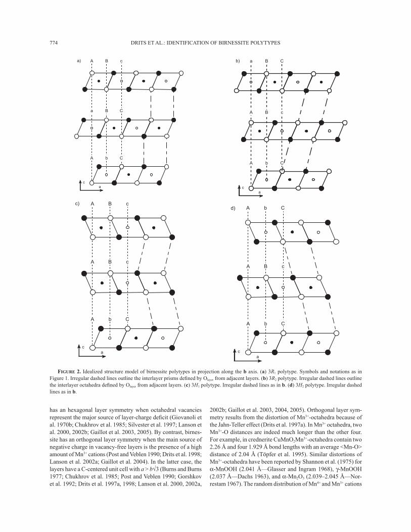
FIGURE 1. Idealized structure model of birnessite polytypes. (a) 1H polytype. Top: projection along the b axis. Open and solid symbols indicate atoms at y = 0 and y = ±½, respectively. Large circles represent Olayer atoms and small circles represent Mnlayer atoms. Dashed lines outline specifi c positions of the close-packing formalism. Irregular dashed lines outline the interlayer octahedra defi ned by Olayer from adjacent layers. Bottom: projection on the a-b plane. The upper surface of the lower layer is shown as light-shaded triangles whereas the lower surface of the upper layer is shown as dark-shaded triangles. Mnlayer of the upper layer are shown as small open circles. (b) 2H1 polytype. Top: projection along the b axis. Irregular dashed lines outline the interlayer prisms defi ned by Olayer from adjacent layers. Bottom: projection on the a-b plane. Mnlayer of the lower layer are shown as small solid circles. Other symbols as in a. (c) 2H2 polytype. Top: projection along the b axis. Irregular dashed lines as in a. Bottom: projection on the a-b plane. Symbols and notations as in a.
DRITS ET AL.: IDENTIFICATION OF BIRNESSITE POLYTYPES774
has an hexagonal layer symmetry when octahedral vacancies represent the major source of layer-charge defi cit (Giovanoli et al. 1970b; Chukhrov et al. 1985; Silvester et al. 1997; Lanson et al. 2000, 2002b; Gaillot et al. 2003, 2005). By contrast, birnes-site has an orthogonal layer symmetry when the main source of negative charge in vacancy-free layers is the presence of a high amount of Mn3+ cations (Post and Veblen 1990; Drits et al. 1998; Lanson et al. 2002a; Gaillot et al. 2004). In the latter case, the layers have a C-centered unit cell with a > b√3 (Burns and Burns 1977; Chukhrov et al. 1985; Post and Veblen 1990; Gorshkov et al. 1992; Drits et al. 1997a, 1998; Lanson et al. 2000, 2002a,
2002b; Gaillot et al. 2003, 2004, 2005). Orthogonal layer sym-metry results from the distortion of Mn3+-octahedra because of the Jahn-Teller effect (Drits et al. 1997a). In Mn3+ octahedra, two Mn3+-O distances are indeed much longer than the other four. For example, in crednerite CuMnO2Mn3+-octahedra contain two 2.26 Å and four 1.929 Å bond lengths with an average <Mn-O> distance of 2.04 Å (Töpfer et al. 1995). Similar distortions of Mn3+-octahedra have been reported by Shannon et al. (1975) for α-MnOOH (2.041 Å—Glasser and Ingram 1968), γ-MnOOH (2.037 Å—Dachs 1963), and α-Mn2O3 (2.039–2.045 Å—Nor-restam 1967). The random distribution of Mn4+ and Mn3+ cations
ac
Aa) B c
a B C
A b C
ac
ab) B C
A B c
A b C
ac
Ac) B c
A B c
A b C
ac
d)
A B c
A b C
A b C
FIGURE 2. Idealized structure model of birnessite polytypes in projection along the b axis. (a) 3R1 polytype. Symbols and notations as in Figure 1. Irregular dashed lines outline the interlayer prisms defi ned by Olayer from adjacent layers. (b) 3R2 polytype. Irregular dashed lines outline the interlayer octahedra defi ned by Olayer from adjacent layers. (c) 3H1 polytype. Irregular dashed lines as in b. (d) 3H2 polytype. Irregular dashed lines as in b.

DRITS ET AL.: IDENTIFICATION OF BIRNESSITE POLYTYPES 775
combined with a random azimutal orientation of the long Mn3+-O bonds of the Mn3+ octahedra would lead to unfavorable steric strains, because of the distortion of Mn3+-octahedra. An ordered distribution of Mn3+-octahedra all having the same azimutal orientation allows minimization of these strains. According to SAED results, in vacancy-free birnessite layers, Mn3+ are dis-tributed in rows parallel to the b axis and have their long Mn3+-O bonds parallel to the a axis (Drits et al. 1997a, 1998; Lanson et al. 2002a; Gaillot et al. 2004). Because of the systematic elon-gation of Mn3+-ocathedra along the a axis and because the four short Mn3+-O distances (1.92–1.93 Å) are similar to Mn4+-O bond lengths (1.912 Å for λ-MnO2), b parameters are similar (2.83–2.85 Å) in most natural and synthetic birnessite samples regardless of the average valency of the Mnlayer (Chukhrov et al. 1985; Post and Veblen 1990; Chen et al. 1996b; Ching et al. 1997a; Drits et al. 1997a, 1998; Kim et al. 1999; Lanson et al. 2000, 2002a, 2002b; Gaillot et al. 2003, 2004, 2005).
The transition from birnessite having layers with hexagonal symmetry to that having pseudo-hexagonal symmetry leads to a modifi cation of symbol notation for the corresponding polytypes. Specifi cally, hexagonal one-, two-, and three-layer polytypes (1H, 2H1, 2H2, 3H1, and 3H2) are changed to the corresponding orthogonal ones (1O, 2O1, 2O2, 3O1, and 3O2) whereas 3R1 and 3R2 are changed to 1M1 and 1M2 monoclinic modifi cations hav-ing –a/3 and +a/3 displacements of adjacent layers along the a axis (Table 1). In 1M1 and 1M2 birnessite, adjacent layers may be shifted along the a axis by values different from ±0.333a (Post and Veblen 1990; Lanson et al. 2002b).
Cation composition, interlayer structure, and polytype diversity
The arrangement of adjacent layers in different polytypes, the presence or absence of vacant layer octahedral sites, the nature of interlayer cations, and their local environments are interrelated structural characteristics. Therefore, it is reasonable to defi ne possible interlayer structures for each particular layer stacking and specifi cally to propose optimum positions for interlayer cations as a function of their ionic radius and valence (Table 2). This approach also relies on existing birnessite structure models (Chukhrov et al. 1978, 1985; Post and Veblen 1990; Drits et al. 1997a, 1998, 2002; Kim et al. 1999; Lanson et al. 2000, 2002a, 2002b; Manceau et al. 2002; Gaillot et al. 2003, 2005). To symbolize positions for interlayer water molecules (H2Ointerlayer) and cations, the capital letters A', B', and C', and corresponding lower case a', b', and c' will be used, respectively.
Polytypes with hexagonal layer symmetry. The presence of layer vacancies allows interlayer cations to share one face with vacant octahedra so as to provide local charge compensation to
undersaturated Olayer. If birnessite interlayers contain relatively small di- or trivalent cations, such as Mn2+,3+, Co2+,3+, Cu2+, Ca2+, and Mg2+, then they are commonly octahedrally coordinated by Olayer bound to layer vacancies and H2Ointerlayer. Depending on the layer stacking mode, the presence of octahedrally coordinated interlayer cations located above and/or below layer vacancies can give rise to three types of bonding between H2Ointerlayer and the nearest Olayer from the adjacent layer. In the fi rst [model 1a (poly-type 1H)], strong H-bonds link these species as they form empty prisms with short H2Ointerlayer-Olayer distances along the prism edges (2.70–2.75 Å—Fig. 3a). In the second [model 2a (polytype 3R1), model 3a (polytype 3R2), and model 4a (polytype 2H1)], Olayer and H2Ointerlayer are linked by weak H-bonds as they form empty octahedra with long H2Ointerlayer-Olayer distances (3.0–3.15 Å—Fig. 3b). In the third interlayer type [model 5a (polytype 2H2), model 6a [polytype 3H1], and model 7a (polytype 3H2)], empty prisms and empty octahedra formed by Olayer and H2Ointerlayer coexist within a given interlayer, with prisms located on one side of the interlayer and octahedra on the opposite one (Fig. 3c).
The presence of tetrahedrally coordinated interlayer cat-ions located above and/or below the vacant layer octahedra in model 3b (polytype 3R2) is associated with the formation of strong H-bonds between H2Ointerlayer coordinating the interlayer cations and nearest Olayer from the adjacent layer. Both spe-cies are superimposed in projection on the a-b plane and thus located close to each other (Fig. 3d). The coexistence of both octahedrally and tetrahedrally coordinated interlayer cations in model 5c (polytype 2H2) leads to the formation of empty prisms between the H2Ointerlayer and Olayer (strong H-bonds) on one side of the interlayer and to short H2Ointerlayer-Olayer distances on the other side (not shown).
On the other hand, if birnessite interlayers contain large mono- or divalent cations, such as K+, Ba2+, Sr2+, or Cs+, then they will be located in the interlayer mid-plane either in octahedra defi ned by Olayer from adjacent layers [model 5b (polytype 2H2), and model 6b (polytype 3H1)] or in interlayer prisms [model 2b (polytype 3R1)]. In the latter case, interlayer prisms share one face with a layer octahedron and three edges with occupied octahedra of the adjacent layer. Local charge compensation is achieved when interlayer cations are distributed so that prisms share a face with vacant layer octahedra. Random distribution of interlayer cations leads to electrostatic repulsion with Mnlayer despite the presence of layer vacancies. Table 2 lists birnessite polytypes consisting of hexagonal vacancy-bearing layers that differ from each other by stacking modes and interlayer structures, which are reasonable from a crystal-chemical point of view.
Polytypes with orthogonal layer symmetry. The interlayer cations for vacancy-free layers should have sixfold coordination by Olayer and H2Ointerlayer, and be distributed so as to avoid direct interaction with Mnlayer. The 1O, 2O2, 3O1, and 3O2 polytypes are thus not suitable to host large mono- or divalent cations as they cannot avoid such interactions. In contrast, the 1M2 and 2O1 polytypes can host these cations in the interlayer mid-plane, with octahedral [model 3e (polytype 1M2)], or prismatic [model 4c (polytype 2O1) and model 4e (polytype 2O1)] coordinations.
Model 2c (polytype 1M1) represents a special case as inter-layer cations cannot be located in a' or b' sites because of the interaction with Mnlayer. However, smaller interlayer cations, such
TABLE 1. List of possible periodic layer stacking modes in birnessite consisting of hexagonal (vacancy-bearing) or orthogonal (vacancy-free) layers
Layer stacking Hexagonal layers Orthogonal layersAbC – AbC ... 1H 1OAbC = CbA = AbC ... 2H1 2O1
AbC – AcB – AbC ... 2H2 2O2
AbC = CaB = BcA = AbC ... 3R1 1M1
AbC – BcA – CaB – AbC ... 3R2 1M2
AbC – AcB – AcB – AbC ... 3H1 3O1
AbC – AcB – CaB – AbC ... 3H2 3O2

DRITS ET AL.: IDENTIFICATION OF BIRNESSITE POLYTYPES776
TABLE 2. Symbolic notations of birnessite consisting of hexagonal (vacancy-bearing) and orthogonal (vacancy-free) layers and diff ering from each other by stacking modes and interlayer structures
Hexagonal layer symmetry Layers with orthogonal symmetryPolyt. Model XRD (Fig.) Notation Polyt. Model XRD (Fig.) Notation1H 1a 5a AbCb‘A‘ C‘b‘AbC... 1O 1b AbCa’B’ B’c’AbC...3R1 2a 5b, 8b AbCb‘A‘ B‘a‘CaBa‘C‘ A‘c‘BcAc‘B‘ C‘b‘AbC... 1M1 2c AbC c’ CaB b’ BcA a’ AbC...3R1 2b 8a, 10a AbC b’/a’ CaB a’/c’ BcA c’/b’ AbC... 2d AbCa’A’ B’b’CaBc’C’ A’a’BcAb’B’ C’c’AbC...3R2 3a 6b, 10b AbCb‘A‘ A‘c‘BcAc‘B‘ B‘a‘CaBa‘C‘ C‘b‘AbC... 1M2 3d 7b AbCa’B’ C’a’BcAb’C’ A’b’CaBc’A’ B’c’AbC...3R2 3b 5c, 6a AbCb‘B‘ C‘c‘BcAc‘C‘ A‘a‘CaBa‘A‘ B‘b‘AbC... 1M2 3e 7a AbC a’ BcA b’ CaB c’ AbC...3R2 3c 6c AbCa‘A‘ A‘a‘BcAb‘B‘ B‘b‘CaBc‘C‘ C‘c‘AbC... 2H1 4a 5d, 8d, 9b AbCb‘A‘ A‘b‘CbAb‘C‘ C‘b‘AbC... 2O1 4c 7c, 9c AbC a’ CbA c’ AbC...2H1 4b 8c AbC a’/C’ CbA c’/A’ AbC... 2O1 4d 7d AbCa’B’ B’a’CbAc’B’ B’c’AbC... 5e, 9a 2O1 4e AbC c’ CbA a’ AbC...2H2 5a AbCb‘A‘ B‘c‘AcBc‘A‘ C‘b‘AbC... 2O2 5d AbCa’B’ C’b’AcBa’C’ B’c’AbC...2H2 5b AbC b’ AcB c’ AbC... 2O2 5e AbCa’A’ C’b’AcBa’A’ B’c’AbC...2H2 5c AbCb‘A‘ C‘c‘AcBc‘A‘ B‘b‘AbC... 3H1 6a 5f, 10c AbCb‘A‘ B‘c‘AcBc‘A‘ B‘c‘AcBc‘A‘ C‘b‘AbC... 3H1 6b 5g, 10d AbC b’ AcB c’ AcB c’ AbC... 3H2 7a AbCb‘A‘ B‘c‘AcBc‘A‘ B‘a‘CaBa‘C‘ C‘b‘AbC...
ac
a) b)
ac
c)
ac
d)
FIGURE 3. Idealized interlayer structure model in projection along the b axis for birnessite polytypes with layer vacancies (hexagonal layer symmetry). Symbols and notations as in Figure 1. (a) 1H polytype with octahedrally coordinated cations above/below vacant layer sites (VITC position—Model 1a). Irregular dashed lines outline the interlayer prisms defi ned by H2Ointerlayer coordinating the interlayer cations and Olayer from adjacent layers (H-bonds). (b) 3R1, 3R2, and 2H1 polytypes with octahedrally coordinated cations above/below vacant layer sites (VITC position—Models 2a, 3a, and 4a, respectively). Irregular dashed lines outline the interlayer octahedra defi ned by H2Ointerlayer coordinating the interlayer cations and Olayer from adjacent layers (weak H-bonds). (c) 2H2, 3H1, and 3H2 polytypes with octahedrally coordinated cations above/below vacant layer sites (VITC position—Models 5a, 6a, and 7a, respectively). Irregular dashed lines outline the interlayer prisms (left) and octahedra defi ned by H2Ointerlayer coordinating the interlayer cations and Olayer from adjacent layers (strong and weak H-bonds, respectively). (d) 3R2 polytype with tetrahedrally coordinated cations above/below vacant layer sites (IVTC position—Model 3b). Irregular dashed line outlines the strong H-bond between H2Ointerlayer coordinating the interlayer cation and Olayer from adjacent layers.

DRITS ET AL.: IDENTIFICATION OF BIRNESSITE POLYTYPES 777
as Na+, can be located, together with H2Ointerlayer, in the interlayer mid-plane above and/or below Olayer of adjacent layers as was described for Na-rich synthetic birnessite, hereafter referred to as NaBi (Lanson et al. 2002b). Similarly, in Na+-saturated 2O1 polytype, the interlayer cations are likely located above and/or below Olayer from adjacent layers (model 4e).
Relatively small di- and trivalent interlayer cations may be located above and/or below empty layer tetrahedra (tridentate cavities) sharing three edges with layer Mn octahedra (VITE sites). Interlayer H2O molecules provide octahedral coordina-tion to these cations and may form either empty prisms [model 3d (polytype 1M2)—Fig. 4a] or empty octahedra [model 1b, (polytype 1O), and model 4d (polytype 2O1)—Fig. 4b], with Olayer from the adjacent layer. Empty prisms and empty octahe-dra coexist within a given interlayer [model 5d (polytype 2O2)] if interlayer cations are octahedrally coordinated. If interlayer cations have both octahedral and tetrahedral coordination, then H2Ointerlayer and Olayer in model 5e (polytype 2O2) form empty prisms and strong H-bonds on either side of a given interlayer. Table 2 lists birnessite polytypes consisting of orthogonal va-cancy-free layers that differ from each other by stacking modes and interlayer structures, which are reasonable from a crystal-chemical point of view.
Vacancy-free birnessite layers can have hexagonal symmetry if the long Mn3+-O bonds of the layer Mn3+-octahedra are ran-domly oriented with respect to the a axis by n60° (Gaillot et al. 2005, 2007). Interlayer cations in such birnessite layers should be distributed so as to avoid direct interaction with the nearest Mnlayer. In this case, suitable interlayer structures are those de-scribed for vacancy-free orthogonal layers (Table 2).
CALCULATION OF XRD PATTERNSThe XRD patterns calculated for polytypes with the same layer symmetry
and periodicity along the c* axis have the same d-spacings, but differ by their hkl intensity distributions. Characterization of layer silicates has shown that structures can be approximated by models for polytype identifi cation purpose. The infl uence of the actual layer structure on the hkl intensity distributions is indeed a second-
order effect compared to the differences among polytypes (Bailey 1980). Structure models were thus proposed for each birnessite variety and corresponding powder XRD patterns were calculated. All calculations were performed using the program developed by Plançon (2002) on the basis of the formalism described by Drits and Tchoubar (1990). No orientation function was considered, and no random stacking faults were introduced for the calculations.
Initial structure modelsIn all structure models, Mnlayer and Olayer occupy special sites in the orthogonal
C-centered unit cell: (0, 0, 0), (0.333, 0, z), and (–0.333, 0, –z), respectively, where z-coordinates (in projection on the c* axis) were equal to 1.00 Å (Post and Veblen 1990; Drits et al. 1998; Lanson et al. 2000, 2002a, 2002b; Gaillot et al. 2003, 2005). According to the close-packing notation, interlayer cations and H2Ointerlayer also occupy special sites. In the initial structure models, the z-coordinates of the interlayer cations (Me) and H2Ointerlayer are the sole variable parameters. The initial z-coordinates of Me and H2O molecules can be estimated from typical Me-O and Me-H2O bond lengths for fourfold- and sixfold-coordinated Me and from elemen-tary geometrical relationships between these bond lengths and corresponding z-coordinates. For example, if an interlayer cation is octahedrally coordinated above and/or below a vacant layer octahedron, then the following equations are deduced from the hexagonal symmetry of the layer (Lanson et al. 2002b):
z(Me) z(O ) d (Me O) b3 z(O ) zlayer
2 2
layer= + − − = + Δ
and
z(H2O) = z(Olayer) + 2∆z.
In the present work, Me-O and Me-H2O interatomic distances were determined from the effective ionic radii given by Shannon (1976). Where applicable, the interlayer atomic positions were adapted from published structural determination of synthetic Na-birnessite (Lanson et al. 2002a), Ca-birnessite (Drits et al. 1998), H-birnessite (Lanson et al. 2000), and K-birnessites (Gaillot et al. 2003, 2005). In the various structure models K, Ca, Mn, Na, and/or Mg were used as interlayer cations. For the different structure models presented in Table 2, corresponding atomic positions and their occupancies are listed in Table 3.
Calculated XRD patternsPowder XRD patterns calculated for the different polytypes are shown in
Figures 5–8, whereas d-values and hkl indices of refl ections observed on the vari-ous patterns are listed in Table 4. Indexing is performed assuming an orthogonal C-centered cell for both hexagonal and orthogonal birnessite. Refl ections in the 36–64 °2θ CuKα range have 20l,11l indices (10l and 01l when using a hexagonal unit cell), whereas they have 31l,02l indices (11l when using a hexagonal unit
FIGURE 4. Idealized interlayer structure model in projection along the b axis for birnessite polytypes with vacancy-free layers (orthogonal layer symmetry). (a) 1M2 polytype with octahedrally coordinated cations above/below empty layer tetrahedra (tridentate cavities) sharing three edges with layer Mn octahedra (VITE position—Model 3d). Symbols and notations as in Figure 1. Irregular dashed lines outline the interlayer prisms defi ned by H2Ointerlayer coordinating the interlayer cations and Olayer from adjacent layers (H-bonds). (b) 1O and 2O1 polytypes with octahedrally coordinated cations above/below empty layer tetrahedra (tridentate cavities) sharing three edges with layer Mn octahedra (VITE position—Models 1b and 4d, respectively). Irregular dashed lines outline the interlayer octahedra defi ned by H2Ointerlayer coordinating the interlayer cations and Olayer from adjacent layers (weak H-bonds).
a)b)
ac
DRITS ET AL.: IDENTIFICATION OF BIRNESSITE POLYTYPES778
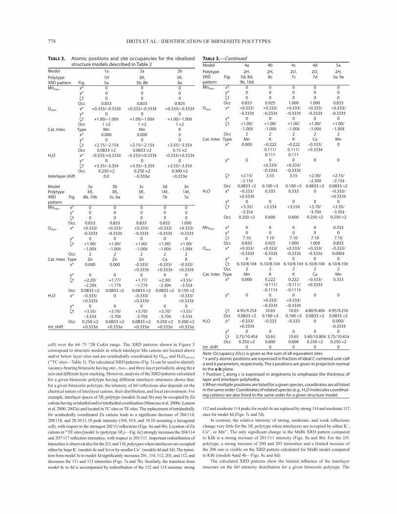
TABLE 3. Atomic positions and site occupancies for the idealized structure models described in Table 2
Model 1a 2a 2bPolytype 1H 3R1 3R1
XRD pattern Fig. 5a 5b, 8b 8aMnlayer x* 0 0 0 y* 0 0 0 ζ† 0 0 0 Occ 0.833 0.833 0.925Olayer x* +0.333/–0.333‡ +0.333/–0.333‡ +0.333/–0.333‡ y* 0 0 0 ζ† +1.00/–1.00‡ +1.00/–1.00‡ +1.00/–1.00‡ Occ 1 ×2 1 ×2 1 ×2Cat. Inter. Type Mn Mn K x* 0.000 0.000 0 y* 0 0 0 ζ† +2.15/–2.15‡ +2.15/–2.15‡ +3.55/–3.55‡ Occ 0.0833 ×2 0.0833 ×2 0.15 ×2H2O x* –0.333/+0.333‡ –0.333/+0.333‡ –0.333/+0.333‡ y* 0 0 0 ζ† +3.35/–3.35‡ +3.35/–3.35‡ +3.55/–3.55‡ Occ 0.250 ×2 0.250 ×2 0.300 ×2Interlayer shift 0.0 –0.333a –0.333a
Model 3a 3b 3c 3d 3ePolytype 3R2 3R2 3R2 1M2 1M2
XRD Fig. 8b, 10b 5c, 6a 6c 7b 7apatternMnlayer x* 0 0 0 0 0 y* 0 0 0 0 0 ζ† 0 0 0 0 0 Occ 0.833 0.833 0.833 0.833 1.000Olayer x* +0.333/ +0.333/ +0.333/ +0.333/ +0.333/ –0.333‡ –0.333‡ –0.333‡ –0.333‡ –0.333‡ y* 0 0 0 0 0 ζ† +1.00/ +1.00/ +1.00/ +1.00/ +1.00/ –1.00‡ –1.00‡ –1.00‡ –1.00‡ –1.00‡ Occ 2 2 2 2 2Cat. Inter. Type Zn Zn Zn Ca K x* 0.000 0.000 –0.333/ –0.333/ –0.333/ +0.333‡ +0.333‡ +0.333‡ y* 0 0 0 0 0 ζ† +2.20/ +1.77/ +1.77/ +2.30/ +3.55/ –2.20‡ –1.77‡ –1.77‡ –2.30‡ –3.55‡ Occ 0.0833 ×2 0.0833 ×2 0.0833 ×2 0.0833 ×2 0.150 ×2H2O x* –0.333/ 0 –0.333/ 0 –0.333/ +0.333‡ +0.333‡ +0.333‡ y* 0 0 0 0 0 ζ† +3.55/ +3.70/ +3.70/ +3.70/ +3.55/ –3.55‡ –3.70‡ –3.70‡ –3.70‡ –3.55‡ Occ 0.250 ×2 0.0833 ×2 0.0833 ×2 0.250 ×2 0.300 ×2Int. shift +0.333a +0.333a +0.333a +0.333a +0.333a
TABLE 3.—ContinuedModel 4a 4b 4c 4d 5aPolytype 2H1 2H1 2O1 2O1 2H2
XRD Fig. 5d, 8d, 8c 7c 7d 5e, 9apattern 9b, 10dMnlayer x* 0 0 0 0 0 y* 0 0 0 0 0 ζ† 0 0 0 0 0 Occ 0.833 0.925 1.000 1.000 0.833Olayer x* +0.333/ +0.333/ +0.333/ +0.333/ +0.333/ –0.333‡ –0.333‡ –0.333‡ –0.333‡ –0.333‡ y* 0 0 0 0 0 ζ† +1.00/ +1.00/ +1.00/ +1.00/ +1.00/ –1.00‡ –1.00‡ –1.00‡ –1.00‡ –1.00‡ Occ 2 2 2 2 2Cat. Inter. Type Mn K K Ca Mn x* 0.000 –0.222 –0.222 –0.333/ 0 0.111/ 0.111/ +0.333‡ 0.111 0.111 y* 0 0 0 0 0 +0.333/ +0.333/ –0.333‡ –0.333‡ ζ† +2.15/ 3.55 3.55 +2.30/ +2.15/ –2.15‡ –2.30‡ –2.15‡ Occ 0.0833 ×2 0.100 ×3 0.100 ×3 0.0833 ×2 0.0833 ×2H2O x* –0.333/ 0.333 0.333 0 –0.333/ +0.333‡ +0.333‡ y* 0 0 0 0 0 ζ† +3.35/ +3.55‡ +3.55‡ +3.70/ +3.35/ –3.35‡ –3.70‡ –3.35‡ Occ 0.250 ×2 0.600 0.600 0.250 ×2 0.250 ×2
Mnlayer x* 0 0 0 0 0.333 y* 0 0 0 0 0 ζ† 7.10 7.10 7.10 7.10 7.10 Occ 0.833 0.925 1.000 1.000 0.833Olayer x* +0.333/ +0.333/ +0.333/ +0.333/ –0.333/ –0.333‡ –0.333‡ –0.333‡ –0.333‡ 0.000‡ y* 0 0 0 0 0 ζ† 6.10/8.10‡ 6.10/8.10‡ 6.10/8.10‡ 6.10/8.10‡ 6.10/8.10‡ Occ 2 2 2 2 2Cat. Inter. Type Mn K K Ca Mn x* 0.000 0.222 0.222 –0.333/ 0.333 –0.111/ –0.111/ +0.333‡ –0.111‡ –0.111‡ y* 0 0 0 0 0 +0.333/ +0.333/ –0.333‡ –0.333‡ ζ† 4.95/9.25‡ 10.65 10.65 4.80/9.40‡ 4.95/9.25‡ Occ 0.0833 ×2 0.100 ×3 0.100 ×3 0.0833 ×2 0.0833 ×2H2O x* –0.333/ –0.333 –0.333 0 0.000/ +0.333‡ –0.333‡ y* 0 0 0 0 0 ζ† 3.75/10.45‡ 10.65 10.65 3.40/10.80‡ 3.75/10.45‡ Occ 0.250 ×2 0.600 0.600 0.250 ×2 0.250 ×2Int. shift 0 0 0 0 0Note: Occupancy (Occ) is given as the sum of all equivalent sites.* x and y atomic positions are expressed in fraction of ideal C-centered unit-cell a and b parameters, respectively. The x positions are given in projection normal to the a-b plane. † Position ζ along c is expressed in angstroms to emphasize the thickness of layer and interlayer polyhedra. ‡ When multiple positions are listed for a given species, coordinates are all listed in the same order. Coordinates of related species (e.g., H2O molecules coordinat-ing cations) are also listed in the same order for a given structure model.
112 and moderate 114 peaks for model 4c are replaced by strong 114 and moderate 112 ones for model 4d (Figs. 7c and 7d).
In contrast, the relative intensity of strong, moderate, and weak refl ections change very little for the 3R1 polytype when interlayers are occupied by either K+, Ca2+, or Mn3+. The only signifi cant change in the MnBi XRD pattern compared to KBi is a strong increase of 201/111 intensity (Figs. 8a and 8b). For the 2H1 polytype, a strong increase of 200 and 203 intensities and a limited increase of the 206 one is visible on the XRD pattern calculated for MnBi model compared to KBi (models 4and 4b—Figs. 8c and 8d).
The calculated XRD patterns show the limited infl uence of the interlayer structure on the hkl intensity distribution for a given birnessite polytype. The
cell) over the 64–75 °2θ CuKα range. The XRD patterns shown in Figure 5 correspond to structure models in which interlayer Mn cations are located above and/or below layer sites and are octahedrally coordinated by Olayer and H2Ointerlayer (VITC sites—Table 3). The calculated XRD patterns (Fig. 5) can be used to identify vacancy-bearing birnessite having one-, two-, and three-layer periodicity along the c axis and different layer stacking. However, analysis of the XRD patterns calculated for a given birnessite polytype having different interlayer structures shows that, for a given birnessite polytype, the intensity of hkl refl ections also depends on the chemical nature of interlayer cations, their distribution, and local environment. For example, interlayer spaces of 3R2 polytype (models 3a and 3b) may be occupied by Zn cations having octahedral and/or tetrahedral coordination (Manceau et al. 2000c; Lanson et al. 2000, 2002a) and located in TC sites or TE sites. The replacement of tetrahedrally for octahedrally coordinated Zn cations leads to a signifi cant decrease of 204/114, 208/118, and 20.10/11.10 peak intensity (104, 018, and 10.10 assuming a hexagonal cell), with respect to the strongest 20l/11l refl ections (Figs. 6a and 6b). Location of Zn cations in IVTE sites [model 3c (polytype 3R2)—Fig. 6c] strongly increases the 204/114 and 207/117 refl ection intensities, with respect to 201/111. Important redistribution of intensities is observed also for the 2O1 and 1M2 polytypes when interlayers are occupied either by large K+ (models 4c and 3e) or by smaller Ca2+ (models 4d and 3d). The transi-tion from model 3e to model 3d signifi cantly increases 201, 110, 112, 203, and 11
–2, and
decreases the 111 and 113 intensities (Figs. 7a and 7b). Similarly, the transition from model 4c to 4d is accompanied by redistribution of the 112 and 114 maxima: strong
DRITS ET AL.: IDENTIFICATION OF BIRNESSITE POLYTYPES 779
intensity distribution is primarily determined by the polytype (Figs. 6–8). As a consequence, identifi cation of birnessite polytypes having either hexagonal or C-centered orthogonal (a > b√3) unit cells may be performed without a priori details of their layer and interlayer structures.
DISCUSSION
Criteria for determination of birnessite polytypes
Birnessite polytypes having the same periodicity along the c axis, but with different layer symmetry, differ from each other
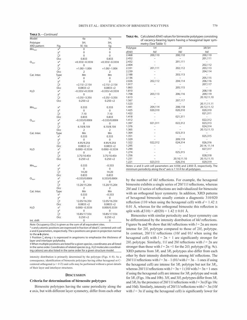
by the number of hkl refl ections. For example, the hexagonal birnessite exhibits a single series of 20l/11l refl ections, whereas 20l and 11l series of refl ections are individualized for birnessite with an orthogonal layer symmetry. In addition, XRD patterns of hexagonal birnessite usually contain a diagnostic 310/020 refl ection (110 when using the hexagonal cell) with d = 1.42 ± 0.01 Å, whereas for the orthogonal birnessite this refl ection is split with d(310) > d(020) = 1.42 ± 0.01 Å.
Birnessites with similar periodicity and layer symmetry can be differentiated by the intensity distribution of hkl refl ections. Figures 9a and 9b show that hkl refl ections with l = 2n are more intense for 2H1 polytype compared to those of 2H2 polytype. In contrast, 20l/11l refl ections (10l and 01l when using the hexagonal cell) with l = 2n + 1 are signifi cantly stronger for 2H2 polytype. Similarly, 11l and 20l refl ections with l = 2n are stronger than those with l = 2n +1 for the 2O1 polytype (Fig. 9c). XRD patterns from 3R1 and 3R2 polytypes also differ from each other by their intensity distributions among hkl refl ections. The 20l/11l refl ections with l = 3n – 1 (01l with l = 3n – 1 ones if using the hexagonal cell) are intense for 3R1 polytype but not for 3R2, whereas 20l/11l refl ections with l = 3n + 1 (10l with l = 3n + 1 ones if using the hexagonal cell) are intense for 3R2 polytype and weak for 3R1 (Figs. 10a and 10b). 3H1 and 3H2 polytypes differ from 3R1 and 3R2 by the presence of 20l/11l refl ections with l = 3n (Figs 10c and 10d). Similarly, intensity of 20l/11l refl ections with l = 3n (10l with l = 3n if using the hexagonal cell) is signifi cantly lower for
TABLE 3.—ContinuedModel 6a 7aPolytype 3H1 3H2
XRD pattern Fig. 5f, 10c 5gMnlayer x* 0 0 y* 0 0 ζ† 0 0 Occ 0.833 0.833Olayer x* +0.333/–0.333‡ +0.333/–0.333‡ y* 0 0 ζ† +1.00/–1.00‡ +1.00/–1.00‡ Occ 2 2Cat. Inter. Type Mn Mn x* 0 0 y* 0 0 ζ† +2.15/–2.15‡ +2.15/–2.15‡ Occ 0.0833 ×2 0.0833 ×2H2O x* –0.333/+0.333‡ –0.333/+0.333‡ y* 0 0 ζ† +3.35/–3.35‡ +3.35/–3.35‡ Occ 0.250 ×2 0.250 ×2
Mnlayer x* 0.333 0.333 y* 0 0 ζ† 7.10 7.10 Occ 0.833 0.833Olayer x* –0.333/0.000‡ –0.333/0.000‡ y* 0 0 ζ† 6.10/8.10‡ 6.10/8.10‡ Occ 2 2Cat. Inter. Type Mn Mn x* 0.333 0.333 y* 0 0 ζ† 4.95/9.25‡ 4.95/9.25‡ Occ 0.0833 ×2 0.0833 ×2H2O x* 0.000/–0.333‡ 0.000/–0.333‡ y* 0 0 ζ† 3.75/10.45‡ 3.75/10.45‡ Occ 0.250 ×2 0.250 ×2
Mnlayer x* 0.333 –0.333 y* 0 0 ζ† 14.20 14.20 Occ 0.833 0.833Olayer x* –0.333/0.000‡ 0.333/0.000‡ y* 0 0 ζ† 13.20/15.20‡ 13.20/15.20‡ Occ 2 2Cat. Inter. Type Mn Mn x* 0.333 –0.333 y* 0 0 ζ† 12.05/16.35‡ 12.05/16.35‡ Occ 0.0833 ×2 0.0833 ×2H2O x* 0.000/–0.333‡ 0.000/0.333‡ y* 0 0 ζ† 10.85/17.55‡ 10.85/17.55‡ Occ 0.250 ×2 0.250 ×2Int. shift 0 0Note: Occupancy (Occ) is given as the sum of all equivalent sites.* x and y atomic positions are expressed in fraction of ideal C-centered unit-cell a and b parameters, respectively. The x positions are given in projection normal to the a-b plane. † Position ζ along c is expressed in angstroms to emphasize the thickness of layer and interlayer polyhedra. ‡ When multiple positions are listed for a given species, coordinates are all listed in the same order. Coordinates of related species (e.g., H2O molecules coordinat-ing cations) are also listed in the same order for a given structure model.
TABLE 4A. Calculated d(hkl) values for birnessite polytypes consisting of vacancy-bearing layers having a hexagonal layer sym-metry (See Table 1)
Polytype 1H 2H 3R/3Hd(hkl) hkl hkl hkl2.468 200,110 200,110 200,1102.452 – – 201,1112.432 – 201,111 –2.404 – – 202,1122.331 201,111 202,112 203,1132.239 – – 204,1142.188 – 203,113 –2.136 – – 205,1152.026 202,112 204,114 206,1161.917 – – 207,1171.863 205,115 –1.810 – – 208,1181.708 203,113 206,116 209,1191.613 – – 20.10,11.101.567 207,117 –1.523 – – 20.11,11.111.441 204,114 208,118 20.12,11.121.425 020,310 020,310 020,3101.422 – – 021,3111.418 – 021,311 –1.412 – – 022,3121.397 021,311 022,312 023,3131.376 – – 024,3141.365 – – 20.13,11.131.364 – 023,313 –1.351 – – 025,3151.329 – 209,119 –1.322 022,312 024,314 026,3161.295 – – 20.14, 11.141.290 – – 027,3171.274 – 025,315 –1.256 – – 028,3181.231 – 20.10,11.10 20.15,11.151.221 023,313 026,316 029,319Notes: a and b unit-cell parameters are 4.936 and 2.850 Å, respectively. The minimum periodicity along the c* axis is 7.10 Å for all polytypes.

DRITS ET AL.: IDENTIFICATION OF BIRNESSITE POLYTYPES780
3H2 than for 3H1 (Figs. 10c and 10d). The intensity distribution among hkl refl ections described above for 3R1, 3R2, 3H1, and 3H2 polytypes remain valid for the equivalent birnessite polytypes with orthogonal layer symmetry (1M1, 1M2, 3O1, 3O2).
Special attention should be paid to identify one- (1H and 1O) and two-layer (2H1 and 2O1) polytypes having the same layer symmetry. The presence of a weak 203/113 refl ection is the sole distinguishing feature, allowing identifi cation of the two-layer polytypes (Figs. 5a and 5b). Note that the difference between
XRD patterns corresponding to these two polytypes is further reduced when 1H layer pairs are present in the 2H1 polytype (that is when AbC – AbC pairs are present in crystals dominated by AbC = CbA = AbC... sequences) as the intensity of the 203/113 refl ection is signifi cantly decreased by the presence of such 1H layer pairs in a mixed-layered structure (not shown).
Stacking faultsThe above-described method can be used not only for the
identifi cation of birnessite polytypes but also to determine the nature of stacking faults that are typically present in natural and synthetic birnessites. Well-defi ned and random stacking faults signifi cantly alter XRD patterns from defective layer structures (for defi nition of well-defi ned and random stacking faults, see Drits and Tchoubar 1990). Well-defi ned stacking faults correspond to the interstratifi cation of layer pairs having the same thickness but different internal structure and interlayer displacements within a periodic polytype. As the result of such interstratifi cation, hkl refl ections are shifted, and their positions become irrational.
Drits and McCarty (1996) have shown that Méring’s rules, initially proposed for basal refl ections (Méring 1949), can be generalized to account for the behavior of hkl refl ections from defective layer structures. According to these generalized rules, hkl refl ections observed from a defective layer structure are located between neighboring hkl refl ections of periodic phases whose fragments (layer pairs in the present case) are interstrati-fi ed. The actual position of hkl refl ections corresponding to the defective layer structure depends on the relative proportion of the structure fragments and on relative intensities of the “involved” hkl refl ections of the periodic phases.
For example, Lanson et al. (2002b—Fig. 3) showed that refl ections of Zn-sorbed birnessite are located between hkl re-fl ections calculated for 3R2 and 1H polytypes and hypothesized that the main 3R2 polytype contained some 1H layer pairs (i.e., AbC – AbC pairs are present in crystals dominated by AbC – BcA – CaB – AbC... sequences). As a result, positions of hkl refl ections of the main 3R2 polytype should indeed be shifted from their ideal position toward those of the defect-free 1H polytype. Accordingly, the best agreement between experimental and calculated XRD patterns was obtained for a defective 3R2 polytype containing 12% of 1H layer pairs (Lanson et al. 2002b). A similar approach may be applied to mixtures containing peri-odic and defective birnessites. For example, Figure 11 shows the best possible agreement between an experimental XRD pattern and that calculated for a mixture of four birnessites: a periodic 2H1 polytype and three defective ones (2O1/2H1, 2H1/3R1, and 3R1/2H1). In the three mixed-layered structures, layer pairs of the 2H1 polytype are randomly interstratifi ed with those of the 2O1 and 3R1 polytypes in proportions 1:1, 7:3, and 1:9, respectively. Note on Figure 11 that each of these mixed-layered structures gives a diagnostic contribution to the calculated XRD pattern (Gaillot et al. 2004).
In our experience, one of the most effective ways to study defective birnessite is to combine the above rules for polytype identifi cation and interstratifi cation to build up starting models for XRD pattern calculation (Manceau et al. 1997; Drits et al. 1998; Lanson et al. 2000, 2002a, 2002b; Gaillot et al. 2003, 2004,
TABLE 4B. Calculated d(hkl) values for birnessite polytypes consisting of vacancy-free layers having an orthogonal layer symmetry (See Table 1)
Polytype 1O 1M1 1M2 2O1/2O2
d(hkl) hkl hkl hkl hkl2.590 200 2002.571 20
–1 201
2.548 201/20–1
2.517 200 200 2.497 110 1102.480 110 110 2.459 111/11
–1
2.433 201/20–1 202/20
–2
2.431 11–1 111
2.356 111/11–1 112/11
–2
2.329 20–2 202
2.272 203/20–3
2.261 111 11–1
2.214 201 20–1
2.209 113/11–3
2.154 11–2 112
2.092 202/20–2 204/20
–4
2.042 112/11–2 114/11
–4
1.972 20–3 203
1.930 112 11–2
1.914 205/20–5
1.875 115/11–5
1.857 202 20–2
1.821 11–3 113
1.747 203/20–3 206/20
–6
1.718 113/11–3 116/11
–6
1.645 20–4 204
1.621 113 11–3
1.597 207/20–7
1.574 117/11–7
1.551 203 20–3
1.530 11–4 114
1.477 310 31–1 311 310
1.469 311/31–1
1.464 204/20–4 208/20
–8
1.447 114/11–4 118/11
–8
1.446 311/31–1 310/31
–2 310/312 312/31
–2
1.425 020 020 020 0201.418 021/02
–1
1.410 313/31–3
1.397 021/02–1 021/02
–1 021/02
–1 022/02
–2
1.384 20–5 205
1.370 114 11–4
1.365 023/02–3
1.364 312/31–2 311 31
–1 314/31
–4
1.363 31–3 313
1.347 209/20–9
1.334 119/11–9
1.322 022/02–2 022/02
–2 022/02
–2 024/02
–4
1.312 204 20–4
1.310 315/31–5
1.299 11–5 115
1.274 025/02–5
1.253 313/31–3 312/31
–4 314/31
–2 316/31
–6
1.245 205/20–5 20.10/20.
–10
1.234 115/11–5 11.10/11.
–10
1.221 023/02–3 023/02
–3 023/02
–3 026/02
–6
Notes: a and b unit–cell parameters are 5.180 and 2.850 Å, respectively. The minimum periodicity along the c* axis is 7.10 Å for all polytypes. The β angle is 103.65 and 76.35° for 1M1 and 1M2 polytypes, respectively.
DRITS ET AL.: IDENTIFICATION OF BIRNESSITE POLYTYPES 781
2005). Defective birnessite may contain layer pairs, which were not reported so far for natural and synthetic periodic birnessite. Therefore, all theoretically possible birnessite polytypes should be considered to determine the nature of stacking faults by com-paring experimental and calculated XRD patterns.
Birnessite polytypes reported for natural and synthetic birnessites
1H Polytype. The fi rst detailed structural study of natural birnessite was performed by Chukhrov et al. (1985) on monomin-eralic birnessite micronodules dredged from the oceanic fl oor. The sample has a one-layer hexagonal unit cell and its structure corresponds to the 1H polytype (model 1a) in which interlayer Mn3+ and Mg2+ cations are octahedrally coordinated above and/or
below vacant layer octahedra. Ca2+ and Na+ cations were also present in the interlayer. This structure model was further sup-ported by X-ray absorption spectroscopy data (Manceau et al. 1992a, 1992b). Analysis of published experimental XRD patterns shows that 1H birnessite dominates in Mn-nodules from ocean and lake fl oors (Burns and Burns 1977; Drits et al. 1985). This 1H polytype occurs also in soil birnessite (Glover 1977).
Birnessite resulting from the equilibration at low pH of NaBi (obtained according to the Giovanoli protocol—Giovanoli et al. 1970b) was studied by Silvester et al. (1997), Drits et al. (1997a), and in more detail by Lanson et al. (2000). This pro-ton-rich birnessite, hereafter referred to as HBi, has a one-layer hexagonal unit cell and a structure similar to model 1a. HBi can thus be considered a synthetic analog of natural 1H birnessite.
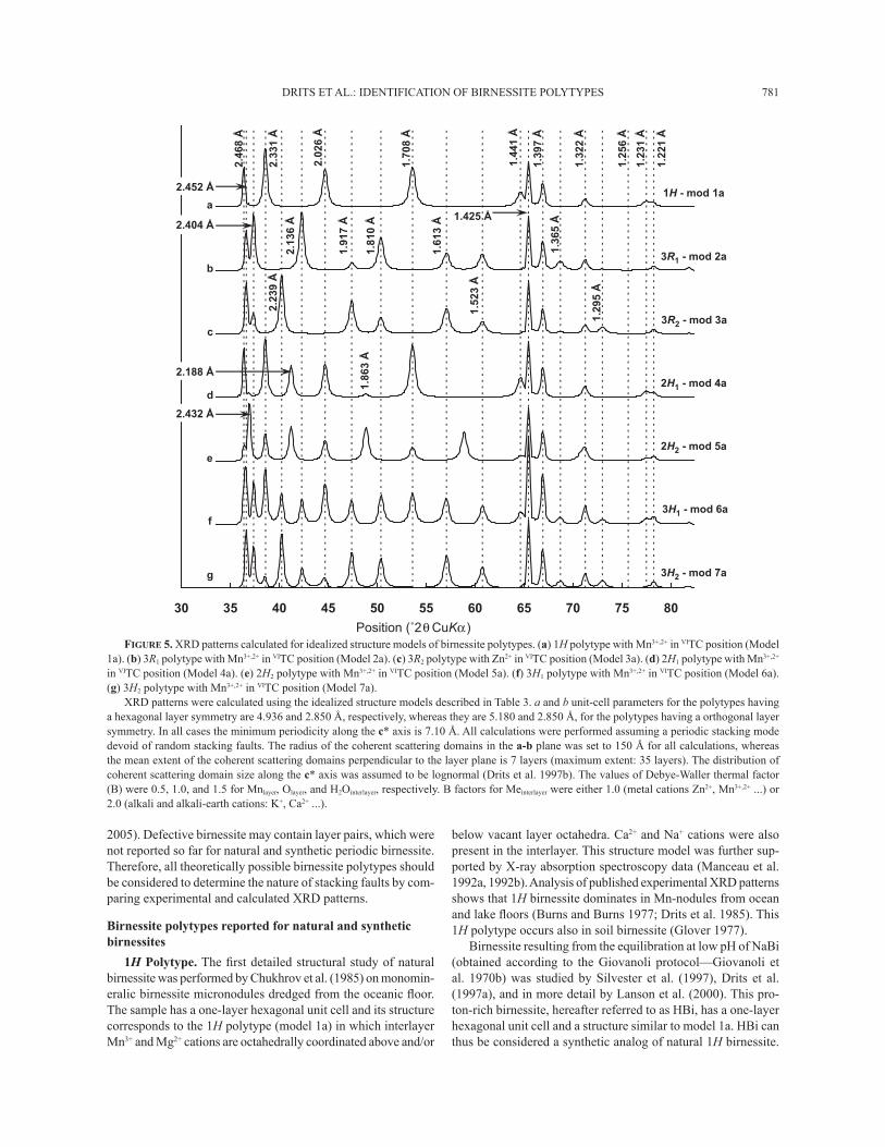
FIGURE 5. XRD patterns calculated for idealized structure models of birnessite polytypes. (a) 1H polytype with Mn3+,2+ in VITC position (Model 1a). (b) 3R1 polytype with Mn3+,2+ in VITC position (Model 2a). (c) 3R2 polytype with Zn2+ in VITC position (Model 3a). (d) 2H1 polytype with Mn3+,2+ in VITC position (Model 4a). (e) 2H2 polytype with Mn3+,2+ in VITC position (Model 5a). (f) 3H1 polytype with Mn3+,2+ in VITC position (Model 6a). (g) 3H2 polytype with Mn3+,2+ in VITC position (Model 7a).
XRD patterns were calculated using the idealized structure models described in Table 3. a and b unit-cell parameters for the polytypes having a hexagonal layer symmetry are 4.936 and 2.850 Å, respectively, whereas they are 5.180 and 2.850 Å, for the polytypes having a orthogonal layer symmetry. In all cases the minimum periodicity along the c* axis is 7.10 Å. All calculations were performed assuming a periodic stacking mode devoid of random stacking faults. The radius of the coherent scattering domains in the a-b plane was set to 150 Å for all calculations, whereas the mean extent of the coherent scattering domains perpendicular to the layer plane is 7 layers (maximum extent: 35 layers). The distribution of coherent scattering domain size along the c* axis was assumed to be lognormal (Drits et al. 1997b). The values of Debye-Waller thermal factor (B) were 0.5, 1.0, and 1.5 for Mnlayer, Olayer, and H2Ointerlayer, respectively. B factors for Meinterlayer were either 1.0 (metal cations Zn2+, Mn3+,2+ ...) or 2.0 (alkali and alkali-earth cations: K+, Ca2+ ...).
30 35 40 45 50 55 60 65 70 75 80
Position (˚2 )θ CuKα
2.33
1 Å
2.02
6 Å
1.70
8 Å
1.44
1 Å
1.425 Å
1.25
6 Å
1.39
7 Å
1.32
2 Å
2.46
8 Å
1.29
5 Å
1.36
5 Å
1.52
3 Å
1.61
3 Å
1.81
0 Å
1.86
3 Å
1.91
7 Å
2.13
6 Å
2.188 Å
2.23
9 Å
2.404 Å
2.432 Å
2.452 Å
1.23
1 Å
1.22
1 Å
b
c
f
d
e
g
a
3R1 - mod 2a
3R2 - mod 3a
3H1 - mod 6a
2H1 - mod 4a
2H2 - mod 5a
3H2 - mod 7a
1H - mod 1a
DRITS ET AL.: IDENTIFICATION OF BIRNESSITE POLYTYPES782
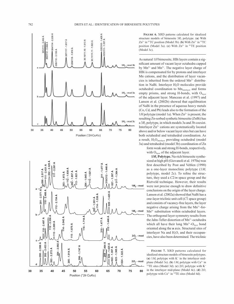
FIGURE 6. XRD patterns calculated for idealized structure models of birnessite 3R2 polytype. (a) With Zn2+ in IVTC position (Model 3b). (b) With Zn2+ in VITC position (Model 3a). (c) With Zn2+ in IVTE position (Model 3c).
Position (°2θ CuKα)
30 35 40 45 50 55 60 65 70 75 80
201
- 2.
571
Å
112
- 2.
356
Å
111
- 2.
261
Å
1M2 - mod 3
1M2 - mod 3
2O1 - mod
2O1 - mod 4
a
b
c
d
202
- 2.
329
Å
200
- 2.
517
Å11
0 -
2.48
0 Å
111
- 2.
431
Å
112
- 2.
154
Å
112
- 1.
930
Å
203
- 1.
972
Å
113
- 1.
821
Å
202
- 1.
857
Å
113
- 1.
621
Å
204
- 1.
645
Å
114
- 1.
530
Å20
3 -
1.55
1 Å
311
- 1.
477
Å
310/
312
- 1.
446
Å02
0 -
1.42
5 Å
021
- 1.
397
Å
311
- 1.
364
Å
200
- 2.
590
Å11
0 -
2.49
7 Å
202
- 2.
433
Å
113
- 2.
209
Å20
3 -
2.27
2 Å
204
- 2.
092
Å
205
- 1.
914
Å
206
- 1.
747
Å
114
- 2.
042
Å
115
- 1.
875
Å
116
- 1.
718
Å
310
- 1.
477
Å20
8 -
1.46
4 Å
312
- 1.
446
Å02
0 -
1.42
5 Å
022
- 1.
397
Å
023
- 1.
365
Å
024
- 1.
322
Å FIGURE 7. XRD patterns calculated for idealized structure models of birnessite polytypes. (a) 1M2 polytype with K+ in the interlayer mid-plane (Model 3e). (b) 1M2 polytype with Ca2+ in VITE sites (Model 3d). (c) 2O1 polytype with K+ in the interlayer mid-plane (Model 4c). (d) 2O1 polytype with Ca2+ in VITE sites (Model 4d).
As natural 1H birnessite, HBi layers contain a sig-nifi cant amount of vacant layer octahedra capped by Mn2+ and Mn3+. The negative layer charge of HBi is compensated for by protons and interlayer Mn cations, and the distribution of layer vacan-cies is inherited from the ordered Mn3+ distribu-tion in NaBi. Interlayer H2O molecules provide octahedral coordination to Mninterlayer and forms empty prisms, and strong H-bonds, with Olayer of the adjacent layer. Manceau et al. (1997) and Lanson et al. (2002b) showed that equilibration of NaBi in the presence of aqueous heavy metals (Co, Cd, and Pb) leads also to the formation of the 1H polytype (model 1a). When Zn2+ is present, the resulting Zn-sorbed synthetic birnessite (ZnBi) has a 3R2 polytype, in which models 3a and 3b coexist. Interlayer Zn2+ cations are systematically located above and/or below vacant layer sites but can have both octahedral and tetrahedral coordination. As a result, H2Ointerlayer providing octahedral (model 3a) and tetrahedral (model 3b) coordination of Zn
form weak and strong H-bonds, respectively, with Olayer of the adjacent layer.
1M1 Polytype. Na-rich birnessite synthe-sized at high pH (Giovanoli et al. 1970a) was fi rst described by Post and Veblen (1990) as a one-layer monoclinic polytype (1M1 polytype, model 2c). To refi ne the struc-ture, they used a C2/m space group and the Rietveld technique. However, their results were not precise enough to draw defi nitive conclusions on the origin of the layer charge. Lanson et al. (2002a) showed that NaBi has a one-layer triclinic unit cell (C–1 space group) and consists of vacancy-free layers, the layer negative charge arising from the Mn3+-for-Mn4+ substitution within octahedral layers. The orthogonal layer symmetry results from the Jahn-Teller distortion of Mn3+-octahedra which all have their long Mn3+-Olayer bond oriented along the a axis. Structural sites of interlayer Na and H2O, and their occupan-cies, have also been determined. The triclinic

DRITS ET AL.: IDENTIFICATION OF BIRNESSITE POLYTYPES 783
character of NaBi originates from a small layer displacement along the b axis.
NaBi varieties with different monovalent and divalent cations that were exchanged for Na+ were studied by Post and Veblen (1990), Kuma et al. (1994), and Bartoli (1997). XRD patterns of these different birnessites can be indexed with a one-layer monoclinic unit cell whose parameters depend on the interlayer cation. However, essential details of these birnessites remain poorly understood. For example, Mg2+ cations in Mg-exchanged birnessite (MgBi) are supposedly located almost above or below octahedral sites (Post and Veblen 1990). Such a location is pos-sible for interlayer Mg2+ cations only if the underlying octahedral sites are vacant, NaBi layers being vacancy-free.
Similarly, Bartoli (1997) reported in K-exchanged birnessite the location of K+ cations in either a' or b' sites, whereas the presence of K+ cations in these sites would lead to their direct interaction with Mnlayer from adjacent layers, as can be seen from symbolic notations (Model 2c—Table 2). Post and Veblen (1990) reported K+ positions in KBi that are shifted from the center of the interlayer prism toward its edges.
Ca2+-for-Na+ exchange in NaBi dramatically modifi es the initial one-layer triclinic structure of NaBi (model 2c) leading
to a four-layer polytype in which layer pairs having orthogonal stacking are shifted alternately by ±b/2 along the b axis (Drits et al. 1998). Gorshkov et al. (1992) described an occurrence of natural Ca-bearing birnessite, which was analogous to the synthetic Ca-exchanged variety of NaBi.
3R1 Polytype. Chen et al. (1996b) synthesized K-rich birnes-site (KBi) with a 3R1 unit cell (model 2b). The KBi layers contain only Mn4+ and vacancies. From the refi nement of integrated intensities they concluded that both K+ and H2Ointerlayer were not located in the prism’s centers (a' and b' sites), as in the idealized model 2b, but rather in the center of the prism’s faces. Gaillot et al. (2005) further refi ned this structure and showed that in-terlayer prisms contain three possible K sites, each shifted from the faces of the prism toward its center. Similar positions of interlayer cations were found for Cs+-, Ba2+-, and Sr2+-exchanged KBi (Gaillot et al. in prep.). The Ca2+-for-K+ exchange in KBi modifi es the initial layer stacking from the 3R1 polytype (model 2b) to the 1H one (model 1a). The driving force for the KBi-to-CaBi transformation is likely the possibility of forming strong H-bonds between H2Ointerlayer providing octahedral coordination to Ca cations and Olayer of the adjacent layer (model 1a). Using mild hydrothermal conditions, Chen et al. (1996a) and Gaillot et
Position (º2θ CuKα)
30 35 40 45 50 55 60 65 70 75 80
Å 254.2 - 111/102
Å 932.2 - 411/402
Å 631.2 - 511/502
Å 719.1 - 711/702
Å 316.1 - 01.1 1/0 1.02
Å 5 24 .1 - 0 1 3 /0 20
Å 018.1 - 811/802
Å 7 93.1 - 3 13/320
Å 404.2 - 211/202
Å 325.1 - 11.11/ 11.02
Å 864.2 - 011/002
Å 620. 2 - 4 11/ 40 2
Å 368.1 - 511/5 02
Å 881. 2 - 311/302
020/310 - 1.425 Å
Å 144.1 - 811/802
022/312 - 1.397 Å
Å 133.2 - 211/202
Å 807. 1 - 61 1/6 02
3R1 - mod 2b
3R1 - mod 2a
2H1 - mod 4b
2H1 - mod 4a
a
b
c
d
FIGURE 8. XRD patterns calculated for idealized structure models of birnessite polytypes. (a) 3R1 polytype with K+ in the interlayer mid-plane (Model 2b). (b) 3R1 polytype with Mn3+,2+ in VITC position (Model 2a). (c) 2H1 polytype with K+ in the interlayer mid-plane (Model 4b). (d) 2H1 polytype with Mn3+,2+ in VITC position (Model 4a).
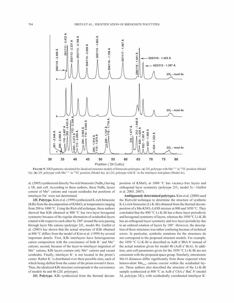
DRITS ET AL.: IDENTIFICATION OF BIRNESSITE POLYTYPES784
al. (2005) synthesized directly Na-rich birnessite (NaBih) having a 3R1 unit cell. According to these authors, these NaBih layers consist of Mn4+ cations and vacant octahedra but positions of interlayer Na+ were not determined.
2H1 Polytype. Kim et al. (1999) synthesized K-rich birnessite (KBi) from the decomposition of KMnO4 at temperatures ranging from 200 to 1000 °C. Using the Rietveld technique, these authors showed that KBi obtained at 800 °C has two-layer hexagonal symmetry because of the regular alternation of octahedral layers rotated with respect to each other by 180° around the axis passing through layer Mn cations (polytype 2H1, model 4b). Gaillot et al. (2003) has shown that the actual structure of KBi obtained at 800 °C differs from the model of Kim et al. (1999) by several important details. First, KBi interlayers have heterogeneous cation composition with the coexistence of both K+ and Mn3+ cations; second, because of the layer-to-interlayer migration of Mn3+ cations, KBi layers contain only Mn4+ cations and vacant octahedra. Finally, interlayer K+ is not located in the prism’s center. Rather K+ is distributed over three possible sites, each of which being shifted from the center of the prism toward it faces. Thus, the idealized KBi structure corresponds to the coexistence of models 4a and 4b (2H1 polytype).
2O1 Polytype. KBi synthesized from the thermal decom-
position of KMnO4 at 1000 °C has vacancy-free layers and orthogonal layer symmetry (polytype 2O1, model 5c—Gaillot et al. 2005, 2007).
Ambiguously determined polytypes. Kim et al. (2000) used the Rietveld technique to determine the structure of synthetic K-Li-rich birnessite (Li-K-Bi) obtained from the thermal decom-position of a Mn-KNO3-LiOH mixture at 800 and 1050 °C. They concluded that the 800 °C Li-K-Bi has a three-layer periodicity and hexagonal symmetry of layers, whereas the 1050 °C Li-K-Bi has an orthogonal layer symmetry and two-layer periodicity due to an ordered rotation of layers by 180°. However, the descrip-tion of these structures was rather confusing because of technical errors. In particular, symbolic notations for the structures do not correspond to the proposed structure models. For example, the 1050 °C Li-K-Bi is described as AaB a' BbA b' instead of the actual notation given for model 4b (AcB a' BcA). In addi-tion, unit-cell parameters given for the 1050 °C Li-K-Bi are not consistent with the proposed space group. Similarly, interatomic Mn-O distances differ signifi cantly from those expected when heterovalent Mnlayer cations coexist within the octahedral lay-ers. These authors also described the structure of the Li-K-Bi sample synthesized at 800 °C as AcB a' CbA c' BaC b' (model 3d, polytype 3R2), with octahedrally coordinated interlayer K+
Position (˚2θ CuKα)
30 35 40 45 50 55 60 65 70 75 80
Å 864.2 - 011/002
Å 620.2 - 411/402
Å 368.1 - 511/502
Å 2 72. 2 - 3 02
020/310 - 1.425 Å
Å 144.1 - 811/802
022/312 - 1.397 Å
Å 133.2 - 211/202
Å 807.1 - 611/602
2H2 - mod 5a
2H1 - mod 4a
2O1 - mod 4c
a
b
c
Å 234.2 - 111/102
Å 76 5.1 - 711 /70 2
Å 09 5.2 - 002
Å 290.2 - 402
Å 41 9.1 - 502
Å 774.1 - 013
Å 334. 2 - 202
Å 7 47.1 - 602
Å 8 45.2 - 10 2
Å 794. 2 - 0 11
Å 653.2 - 21 1 Å 902. 2 - 311
Å 2 40. 2 - 4 11 Å 578. 1 - 5 11
Å 817.1 - 61 1
Å 644. 1 - 213Å 524.1 - 02 0
Å 793.1 - 220
Å 56 3.1 - 320
Å 22 3.1 - 42 0
Å 881.2 - 311/302
FIGURE 9. XRD patterns calculated for idealized structure models of birnessite polytypes. (a) 2H2 polytype with Mn3+,2+ in VITC position (Model 5a). (b) 2H1 polytype with Mn3+,2+ in VITC position (Model 4a). (c) 2O1 polytype with K+ in the interlayer mid-plane (Model 4c).

DRITS ET AL.: IDENTIFICATION OF BIRNESSITE POLYTYPES 785
cations. However, atomic coordinates reported for this sample (Table 1—Kim et al. 2000) correspond to polytype 3R1 (model 2b) with interlayer K+ having prismatic coordination. This latter structure model is consistent with the experimental XRD pat-tern reported for this sample (Fig. 4—Kim et al. 2000), which is similar to those obtained by Chen et al. (1996a) and Gaillot et al. (2005) from 3R1 polytypes (model 2b) synthesized under mild hydrothermal conditions. All these experimental patterns are similar to the one displayed on Figure 8a.
Turbostratic samples. Finally, one has to note that among different natural environments, and especially in soils, turbostrat-ic birnessite is extremely common. For example, turbostratic birnessite has been reported as resulting from the bacterial oxidation of Mn2+ by different strains (Mandernack et al. 1995; Villalobos et al. 2003; Jurgensen et al. 2004; Bargar et al. 2005; Webb et al. 2005) and from abiotic processes (Mandernack et al. 1995). However, so far there is little unambiguous information derived from XRD data on the structure and crystal chemistry of these varieties. Most often the structural characterization of disordered birnessite is limited to the description of 00l peak positions as a function of relative humidity to assess the lamellar character of these “poorly crystalline birnessites.” The position
of hkl refl ections has also been used to hypothesize the actual layer symmetry (and thus the origin of the layer charge of these varieties) but without much experimental support (Villalobos et al. 2003; Jurgensen et al. 2004; Webb et al. 2005).
However, as described, birnessite having different layer symmetry may be unambiguously distinguished from each other from the shape of their hk bands (Fig. 12). A shoulder, resulting from the individualization of 20 and 11 refl ections, is indeed visible on the low-angle side of the main maximum of the 20,11 band for orthogonal modifi cations (at ~2.55 and 2.45 Å, respectively—Fig. 12b), whereas this shoulder is logi-cally absent for hexagonal modifi cations (Fig. 12a). Similarly, the 31,02 band of the orthogonal modifi cations contains two distinct maxima (~1.474 and 1.422 Å—Fig. 12b) which are merged for the hexagonal modifi cations (peak at ~1.422 Å—Fig. 12a). The features described for the orthogonal modifi cations are like those reported for the Mn oxides resulting from the oxidation of Mn2+ by Bacillus sp. strain SG-1 (Fig. 3 in Webb et al. 2005), indicating the presence of a high proportion of Mn3+ within the octahedral layers of this birnessite. The presence of Mn3+-rich rows in vacancy-free layers, as in NaBi, is also supported by the splitting of the 8 Å–1 feature in the EXAFS spectra (Fig. 5 in
30 35 40 45 50 55 60 65 70 75 80
Å 254.2 - 111/102
Å 932.2 - 411/402
020/310 - 1.425 Å
Å 018.1 - 811/802
023/313 - 1.397 Å
Å 404.2 - 211/202
Å 316.1 - 01.11/01.02
Å 7 19. 1 - 711/70 2
Å 1 33.2 - 311 /3 02
Å 6 20. 2 - 6 11/ 602
Å 807 .1 - 91 1/ 902
Å 631.2 - 511/502
Å 325 .1 - 11.11 /11 .02
Å 144 .1 - 21. 11/21.02
3R1 - mod 2b
3R2 - mod 3a
3H1 - mod 6a
3H2 - mod 7a
a
b
c
d
Position (˚2 )θ CuKαFIGURE 10. XRD patterns calculated for idealized structure models of birnessite polytypes. (a) 3R1 polytype with K+ in the interlayer mid-plane
(Model 2b). (b) 3R2 polytype with Zn2+ in VITC position (Model 3a). (c) 3H1 polytype with Mn3+,2+ in VITC position (Model 6a). (d) 3H2 polytype with Mn3+,2+ in VITC position (Model 7a).

DRITS ET AL.: IDENTIFICATION OF BIRNESSITE POLYTYPES786
Webb et al. 2005) which has been described as characteristic of the presence of Mn3+-rich rows in the octahedral Mn layer leading to its orthogonal symmetry (Fig. 9 in Gaillot et al. 2003; Fig. 6 in Marcus et al. 2004; Fig. 5 in Manceau et al. 2004; Manceau et al. 2005). To our knowledge, XRD patterns of all other tur-bostratic varieties reported so far in the literature correspond to hexagonal modifi cations.
In addition, Villalobos et al. (2006) demonstrated the high sensitivity of XRD profi les to the layer and interlayer structure of turbostratic phyllomanganates. In their study, Villalobos et al. (2006) observed contrasting experimental modulations of the 20,11 and 31,02 bands, and successfully reproduced them assuming a turbostratic stacking. In this case, the position and profi le of the bands depend essentially on the amount and atomic coordinates of both layer and interlayer species, and these authors were able to determine the amount of vacant layer sites, as well as the amount and coordinates of both “heavy” (Mn3+,2+) and “light” (Na+, K+, H2Ointerlayer) interlayer species. Such calculations also provided them with an estimate of the lateral extension of the octahedral layers (Drits and Tchoubar 1990; Jurgensen et al. 2004; Villalobos et al. 2006). The infl uence of the layer and interlayer structure on calculated profi les for 20,11 and 31,02 bands is illustrated in Figure 13. As compared to the structure model 1a (Fig. 13a), decreasing both the proportion of interlayer Mn and layer vacan-cies from 0.167 to 0.075 broadens the lineshape of the 20,11 and smoothes out the scattering dip at ~ 45 °2θ CuKα, thus rendering
FIGURE 11. Comparison between experimental and calculated XRD patterns for a K-rich birnessite sample synthesized at 700 °C from the thermal decomposition of KMnO4 (Gaillot et al. 2004). Experimental data are shown as crosses, whereas calculated profi les are shown as solid lines. Arrows outline the misfi ts between experimental and calculated patterns. Only 20l and 11l refl ections are calculated. Atomic coordinates and other structural parameters used for the calculations as described by Gaillot et al. (2004). (a) Optimum model and difference plot. The optimum model includes contributions from a defect-free 2H1 polytype and from 2O1/2H1, 2H1/3R1, and 3R1/2H1 mixed-layered structures (relative proportions 7:29:41:23). (b) Calculation made replacing the optimum 2O1/2H1 contribution (2O1:2H1 ratio 50:50) by a defect-free 2H1 contribution. (c) Calculation made by subtracting the 2H1/3R1 contribution (2H1:3R1 ratio 70:30) from the optimum model. (d) Calculation made by subtracting the 3R1/2H1 contribution (3R1:2H1 ratio 90:10) from the optimum model. Adapted from Gaillot et al. (2004).
34 38 42 46 50 54
Position (˚2θ CuKα)
aRwp = 9.1%
d
c
b
FIGURE 12. XRD patterns calculated for idealized structure models of turbostratic birnessite. (a) Birnessite with Mn3+,2+ in VITC position (Model 1a). (b) Birnessite with 0.67 Na+ and H2Ointerlayer in the interlayer mid-plane above below Olayer (Model 2c). Calculations were performed assuming a turbostratic stacking (100% random stacking faults). The radius of the coherent scattering domains in the a-b plane was set to 75 Å. All other parameters for XRD pattern calculations as described for Figure 5.
FIGURE 13. XRD patterns calculated for idealized structure models of turbostratic birnessite having hexagonal layer symmetry. (a) Birnessite with 0.833 vacant layer sites capped by Mn3+,2+ in VITC position (Model 1a). (b) Birnessite with 0.925 vacant layer sites capped by Mn3+,2+ in VITC position. (c) Birnessite with 0.833 vacant layer sites capped by Mn3+,2+ in VITE position (similar to Model 3d with interlayer Mn3+,2+ cations). (d) Birnessite with 0.925 vacant layer sites and interlayer Na+ (0.30 per octahedron) and H2O molecules (0.90 per octahedron) in c' position (+1/3, 0, 1/2). (e) Birnessite with 0.925 vacant layer sites and interlayer K+ (0.30 per octahedron) and H2O molecules (0.90 per octahedron) in a' (–0.222, 0, 1/2) and c' (+1/3, 0, 1/2) positions, respectively. Calculations were performed as described for Figure 12.
DRITS ET AL.: IDENTIFICATION OF BIRNESSITE POLYTYPES 787
the calculated hump at ~50–55 °2θ CuKα less pronounced (Fig. 13b). Moving interlayer Mn from the VITC position dramatically modifi es the 20,11 lineshape, as observed when the 0.167 interlayer Mn atoms are located above and/or below the tridentate cavities (VITE sites—Fig. 13c). The sensitivity of the 20,11 profi le to the position of “light” interlayer species is illustrated next by assuming either the presence of Na+ above and/or below Olayer [(0.333, 0.0, 0.5)—Fig. 13d] or that of K+ above/below the tridentate cavities [Position (–0.222, 0, 05) and equivalent positions—Fig. 13e], H2O molecules sitting in both cases above and/or below Olayer. In the second case, the 20,11 band is broadened and the “hump” observed at ~50 °2θ CuKα in Figure 13d is both shifted toward higher angles and smoothened out. Similar modulations can however result from the partial ordering of the layer stacking (e.g., Ben Brahim et al. 1983, 1984; Drits and Tchoubar 1990; Viani et al. 2002). Special attention should thus be paid to the structural interpretation of these modulations, and, in this respect, verifying the structural XRD model with independent data from another structural technique, such as EXAFS spectroscopy, is always warranted.
ACKNOWLEDGMENTSV.A.D. is grateful to the Environmental Geochemistry Group of the LGIT
(Grenoble, France) and to the Russian Science Foundation for fi nancial support. V.A.D. and B.L. acknowledge fi nancial support from CNRS/PICS709 program. The manuscript greatly benefi ted from the remarks of two anonymous reviewers and from the editorial assistance of AE Laurence Garvie.
REFERENCES CITEDAronson, B.J., Kinser, A.K., Passerini, S., Smyrl, W.H., and Stein, A. (1999) Syn-
thesis, characterization, and electrochemical properties of magnesium birnessite and zinc chalcophanite prepared by a low-temperature route. Chemistry of Materials, 11, 949–957.
Bach, S., Henry, M., Baffi er, N., and Livage, J. (1990) Sol-gel synthesis of man-ganese oxides. Journal of Solid State Chemistry, 88, 325–333.
Bach, S., Pereira-Ramos, J.-P., and Bafi er, N. (1993) Electrochemical sodium insertion into the sol-gel birnessite manganese dioxide. Electrochimica Acta, 38, 1695–1698.
Bailey, S.W. (1980) Structures of layer silicates. In G.W. Brindley and G. Brown, Eds., Crystal Structures of Clay Minerals and their X-ray Identifi cation, p. 1–123. Mineralogical Society, London.
——— (1988) Hydrous Phyllosilicates (exclusive of micas), 19, 725 p. Reviews in Mineralogy, Mineralogical Society of America, Chantilly, Virginia.
Bargar, J.R., Tebo, B.M., Bergmann, U., Webb, S.M., Glatzel, P., Chiu, V.Q., and Villalobos, M. (2005) Biotic and abiotic products of Mn(II) oxidation by spores of the marine Bacillus sp. strain SG-1. American Mineralogist, 90, 143–154.
Bartoli, C. (1997) Contribution à l’étude structurale des birnessites monocliniques saturées au potassium et au rubidium, 234 p. Ph.D. thesis, Orléans University, France.
Ben Brahim, J., Besson, G., and Tchoubar, C. (1983) Layer succession and water molecules arrangement in a homogeneous two-water layer Na-smectite. In J. Konta, Ed., 5th Meeting of the European Clay Groups, p. 65–75. Univerzita Karlova, Prague.
——— (1984) Etude des profi ls des bandes de diffraction X d’une beidellite-Na hydratée à deux couches d’eau. Détermination du mode d’empilement des feuillets et des sites occupés par l’eau. Journal of Applied Crystallography, 17, 179–188.
Bookin, A.S. and Drits, V.A. (1993) Polytype diversity of the hydrotalcite-like minerals. I. Possible polytypes and their diffraction features. Clays and Clay Minerals, 41, 551–557.
Burns, R.G. and Burns, V.M. (1977) The mineralogy and crystal chemistry of deep-sea manganese nodules, a polymetallic resource of the twenty-fi rst century. Philo-sophical Transactions of the Royal Society of London (A), 286, 283–301.
Burns, V.M. and Burns, R.G. (1978) Post-depositional metal enrichment processes inside manganese nodules from the North Equatorial Pacifi c Ocean. Earth and Planetary Science Letters, 39, 341–348.
Chao, T.T. and Theobald, P.K. (1976) The signifi cance of secondary iron and manga-nese oxides in geochemical exploration. Economic Geology, 71, 1560–1569.
Chen, R.J., Chirayil, T., Zavalij, P., and Whittingham, M.S. (1996a) The hydro-thermal synthesis of sodium manganese oxide and a lithium vanadium oxide. Solid State Ionics, 86–88, 1–7.
Chen, R.J., Zavalij, P., and Whittingham, M.S. (1996b) Hydrothermal synthesis and
characterization of KxMnO2·yH2O. Chemistry of Materials, 8, 1275–1280.Ching, S. and Suib, S.L. (1997) Synthetic routes to microporous manganese oxides.
Comments on Inorganic Chemistry, 19, 263–282.Ching, S., Landrigan, J.A., Jorgensen, M.L., Duan, N., Suib, S.L., and O’Young,
C.L. (1995) Sol-Gel synthesis of birnessite from KMnO4 and simple sugars. Chemistry of Materials, 7, 1604–1606.
Ching, S., Petrovay, D.J., Jorgensen, M.L., and Suib, S.L. (1997a) Sol-Gel Syn-thesis of layered Birnessite-Type Manganese Oxides. Inorganic Chemistry, 36, 883–890.
Ching, S., Roark, J.L., Duan, N., and Suib, S.L. (1997b) Sol-Gel route to the tun-neled manganese oxide cryptomelane. Chemistry of Materials, 9, 750–754.
Cho, J., Kim, G.B., Lim, H.S., Kim, C.-S., and Yoo, S.-I. (1999) Improvement of Structural Stability of LiMn2O4 Cathode Material on 55 °C Cycling by Sol-Gel Coating of LiCoO2. Electrochemical and Solid-State Letters, 2, 607–609.
Chukhrov, F.V., Gorschkov, A.I., Rudnitskaya, E.S., and Sivtsov, A.V. (1978) Birnessite characterization. Izvestiya Akademie Nauk, SSSR, Seriya Geo-logicheskaya, 9, 67–76.
Chukhrov, F.V., Sakharov, B.A., Gorshkov, A.I., Drits, V.A., and Dikov, Y.P. (1985) Crystal structure of birnessite from the Pacifi c Ocean. International Geology Review, 27, 1082–1088.
Cornell, R.M. and Giovanoli, R. (1988) Transformation of hausmannite into birnes-site in alkaline media. Clays and Clay Minerals, 36, 249–257.
Dachs, H. (1963) Neutronen- und Röntgenuntersuchungen am Manganit, MnOOH. Zeitschrift für Kristallographie, 118, 303–326.
Delmas, C., Fouassier, C., and Hagenmuller, P. (1980) Structural classifi cation and properties of the layered oxides. Physica B, 99, 81–85.
Drits, V.A. (1987) Electron diffraction and high-resolution electron microscopy of mineral structures, 304 p. Springer Verlag, Berlin.
Drits, V.A. and Bookin, A.S. (2001) Crystal Structure and X-ray Identifi cation of Layered Double Hydroxides. In V. Rives, Ed., Layered Double Hydroxides: Present and Future, p. 41–100. Nova Science Publishers, New York.
Drits, V.A. and McCarty, D.K. (1996) The nature of diffraction effects from illite and illite-smectite consisting of interstratifi ed trans-vacant and cis-vacant 2:1 layers: A semi-quantitative technique for determination of layer-type content. American Mineralogist, 81, 852–863.
Drits, V.A. and Tchoubar, C. (1990) X-ray diffraction by disordered lamellar structures: Theory and applications to microdivided silicates and carbons, 371 p. Springer-Verlag, Berlin.
Drits, V.A., Petrova, V.V., and Gorshkov, A.I. (1985) Manganese minerals of Fe-Mn nodules from the sediments of the central part of Pacifi c Ocean and their post-sedimentation transformation. Lithology and Raw Materials, 3, 17–39.
Drits, V.A., Silvester, E.J., Gorshkov, A.I., and Manceau, A. (1997a) The structure of monoclinic Na-rich birnessite and hexagonal birnessite. Part 1. Results from X-ray diffraction and selected area electron diffraction. American Mineralo-gist, 82, 946–961.
Drits, V.A., Srodon, J., and Eberl, D.D. (1997b) XRD measurement of mean crystal-lite tickness of illite and illite/smectite : Reappraisal of the Kubler index and the Scherrer equation. Clays and Clay Minerals, 45, 461–475.
Drits, V.A., Lanson, B., Gorshkov, A.I., and Manceau, A. (1998) Substructure and superstructure of four-layer Ca-exchanged birnessite. American Mineralogist, 83, 97–118.
Drits, V.A., Lanson, B., Bougerol Chaillout, C., Gorshkov, A.I., and Manceau, A. (2002) Structure of heavy-metal sorbed birnessite: Part 2. Results from electron diffraction. American Mineralogist, 87, 1646–1661.
Feng, Q., Kanoh, H., Miyai, Y., and Ooi, K. (1995) Hydrothermal synthesis of lithium and sodium manganese oxides and their metal ion extraction/insertion reactions. Chemistry of Materials, 7, 1226–1232.
Feng, Q., Sun, E.H., Yanagisawa, K., and Yamasaki, N. (1997a) Synthesis of birnes-site-type sodium manganese oxides by solution reaction and hydrothermal methods. Journal of the Ceramic Society of Japan, 105, 564–568.
Feng, Q., Yanagisawa, K., and Yamasaki, N. (1997b) Synthesis of birnessite-type po-tassium manganese oxide. Journal of Materials Science Letters, 16, 110–112.
Gaillot, A.-C., Flot, D., Drits, V.A., Manceau, A., Burghammer, M., and Lanson, B. (2003) Structure of synthetic K-rich birnessite obtained by high-temperature decomposition of KMnO4. I. Two-layer polytype from 800 °C experiment. Chemistry of Materials, 15, 4666–4678.
Gaillot, A.-C., Drits, V.A., Plancon, A., and Lanson, B. (2004) Structure of synthetic K-rich birnessites obtained by high-temperature decomposition of KMnO4. 2. Phase and structural heterogeneities. Chemistry of Materials, 16, 1890–1905.
Gaillot, A.-C., Lanson, B., and Drits, V.A. (2005) Structure of birnessite obtained from decomposition of permanganate under soft hydrothermal conditions. 1. Chemical and structural evolution as a function of temperature. Chemistry of Materials, 17, 2959–2975.
Gaillot, A.-C., Drits, V.A., Lanson, B., and Manceau, A. (2007) Structure of synthetic K-rich birnessite obtained by high-temperature decomposition of KMnO4. Structure of a two-layer polytype from 1000 °C experiments. Mi-croporous and Mesoporous Materials, 98, 267–282.
Giovanoli, R., Stähli, E., and Feitknecht, W. (1970a) Über Oxidhydroxide des vierwertigen Mangans mit Schichtengitter. 1. Mitteilung: Natriummangan(II
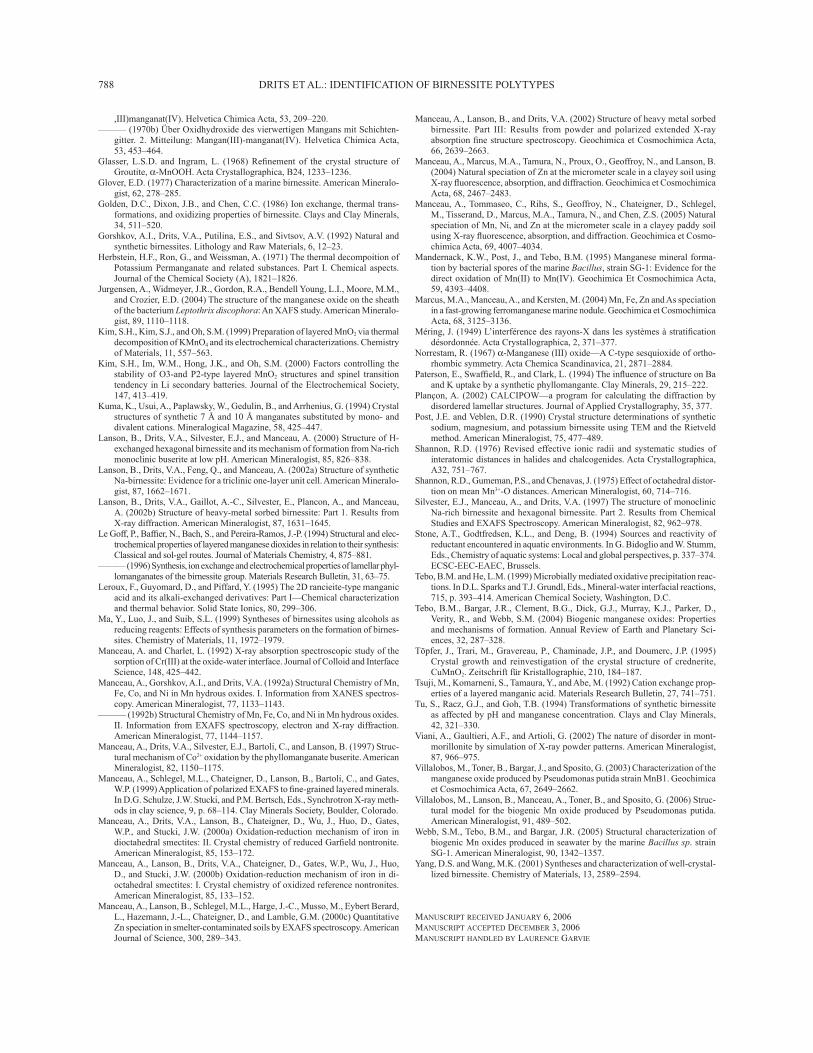
DRITS ET AL.: IDENTIFICATION OF BIRNESSITE POLYTYPES788
,III)manganat(IV). Helvetica Chimica Acta, 53, 209–220.——— (1970b) Über Oxidhydroxide des vierwertigen Mangans mit Schichten-
gitter. 2. Mitteilung: Mangan(III)-manganat(IV). Helvetica Chimica Acta, 53, 453–464.
Glasser, L.S.D. and Ingram, L. (1968) Refi nement of the crystal structure of Groutite, α-MnOOH. Acta Crystallographica, B24, 1233–1236.
Glover, E.D. (1977) Characterization of a marine birnessite. American Mineralo-gist, 62, 278–285.
Golden, D.C., Dixon, J.B., and Chen, C.C. (1986) Ion exchange, thermal trans-formations, and oxidizing properties of birnessite. Clays and Clay Minerals, 34, 511–520.
Gorshkov, A.I., Drits, V.A., Putilina, E.S., and Sivtsov, A.V. (1992) Natural and synthetic birnessites. Lithology and Raw Materials, 6, 12–23.
Herbstein, H.F., Ron, G., and Weissman, A. (1971) The thermal decompoition of Potassium Permanganate and related substances. Part I. Chemical aspects. Journal of the Chemical Society (A), 1821–1826.
Jurgensen, A., Widmeyer, J.R., Gordon, R.A., Bendell Young, L.I., Moore, M.M., and Crozier, E.D. (2004) The structure of the manganese oxide on the sheath of the bacterium Leptothrix discophora: An XAFS study. American Mineralo-gist, 89, 1110–1118.
Kim, S.H., Kim, S.J., and Oh, S.M. (1999) Preparation of layered MnO2 via thermal decomposition of KMnO4 and its electrochemical characterizations. Chemistry of Materials, 11, 557–563.
Kim, S.H., Im, W.M., Hong, J.K., and Oh, S.M. (2000) Factors controlling the stability of O3-and P2-type layered MnO2 structures and spinel transition tendency in Li secondary batteries. Journal of the Electrochemical Society, 147, 413–419.
Kuma, K., Usui, A., Paplawsky, W., Gedulin, B., and Arrhenius, G. (1994) Crystal structures of synthetic 7 Å and 10 Å manganates substituted by mono- and divalent cations. Mineralogical Magazine, 58, 425–447.
Lanson, B., Drits, V.A., Silvester, E.J., and Manceau, A. (2000) Structure of H-exchanged hexagonal birnessite and its mechanism of formation from Na-rich monoclinic buserite at low pH. American Mineralogist, 85, 826–838.
Lanson, B., Drits, V.A., Feng, Q., and Manceau, A. (2002a) Structure of synthetic Na-birnessite: Evidence for a triclinic one-layer unit cell. American Mineralo-gist, 87, 1662–1671.
Lanson, B., Drits, V.A., Gaillot, A.-C., Silvester, E., Plancon, A., and Manceau, A. (2002b) Structure of heavy-metal sorbed birnessite: Part 1. Results from X-ray diffraction. American Mineralogist, 87, 1631–1645.
Le Goff, P., Baffi er, N., Bach, S., and Pereira-Ramos, J.-P. (1994) Structural and elec-trochemical properties of layered manganese dioxides in relation to their synthesis: Classical and sol-gel routes. Journal of Materials Chemistry, 4, 875–881.
——— (1996) Synthesis, ion exchange and electrochemical properties of lamellar phyl-lomanganates of the birnessite group. Materials Research Bulletin, 31, 63–75.
Leroux, F., Guyomard, D., and Piffard, Y. (1995) The 2D rancieite-type manganic acid and its alkali-exchanged derivatives: Part I—Chemical characterization and thermal behavior. Solid State Ionics, 80, 299–306.
Ma, Y., Luo, J., and Suib, S.L. (1999) Syntheses of birnessites using alcohols as reducing reagents: Effects of synthesis parameters on the formation of birnes-sites. Chemistry of Materials, 11, 1972–1979.
Manceau, A. and Charlet, L. (1992) X-ray absorption spectroscopic study of the sorption of Cr(III) at the oxide-water interface. Journal of Colloid and Interface Science, 148, 425–442.
Manceau, A., Gorshkov, A.I., and Drits, V.A. (1992a) Structural Chemistry of Mn, Fe, Co, and Ni in Mn hydrous oxides. I. Information from XANES spectros-copy. American Mineralogist, 77, 1133–1143.
——— (1992b) Structural Chemistry of Mn, Fe, Co, and Ni in Mn hydrous oxides. II. Information from EXAFS spectroscopy, electron and X-ray diffraction. American Mineralogist, 77, 1144–1157.
Manceau, A., Drits, V.A., Silvester, E.J., Bartoli, C., and Lanson, B. (1997) Struc-tural mechanism of Co2+ oxidation by the phyllomanganate buserite. American Mineralogist, 82, 1150–1175.
Manceau, A., Schlegel, M.L., Chateigner, D., Lanson, B., Bartoli, C., and Gates, W.P. (1999) Application of polarized EXAFS to fi ne-grained layered minerals. In D.G. Schulze, J.W. Stucki, and P.M. Bertsch, Eds., Synchrotron X-ray meth-ods in clay science, 9, p. 68–114. Clay Minerals Society, Boulder, Colorado.
Manceau, A., Drits, V.A., Lanson, B., Chateigner, D., Wu, J., Huo, D., Gates, W.P., and Stucki, J.W. (2000a) Oxidation-reduction mechanism of iron in dioctahedral smectites: II. Crystal chemistry of reduced Garfi eld nontronite. American Mineralogist, 85, 153–172.
Manceau, A., Lanson, B., Drits, V.A., Chateigner, D., Gates, W.P., Wu, J., Huo, D., and Stucki, J.W. (2000b) Oxidation-reduction mechanism of iron in di-octahedral smectites: I. Crystal chemistry of oxidized reference nontronites. American Mineralogist, 85, 133–152.
Manceau, A., Lanson, B., Schlegel, M.L., Harge, J.-C., Musso, M., Eybert Berard, L., Hazemann, J.-L., Chateigner, D., and Lamble, G.M. (2000c) Quantitative Zn speciation in smelter-contaminated soils by EXAFS spectroscopy. American Journal of Science, 300, 289–343.
Manceau, A., Lanson, B., and Drits, V.A. (2002) Structure of heavy metal sorbed birnessite. Part III: Results from powder and polarized extended X-ray absorption fi ne structure spectroscopy. Geochimica et Cosmochimica Acta, 66, 2639–2663.
Manceau, A., Marcus, M.A., Tamura, N., Proux, O., Geoffroy, N., and Lanson, B. (2004) Natural speciation of Zn at the micrometer scale in a clayey soil using X-ray fl uorescence, absorption, and diffraction. Geochimica et Cosmochimica Acta, 68, 2467–2483.
Manceau, A., Tommaseo, C., Rihs, S., Geoffroy, N., Chateigner, D., Schlegel, M., Tisserand, D., Marcus, M.A., Tamura, N., and Chen, Z.S. (2005) Natural speciation of Mn, Ni, and Zn at the micrometer scale in a clayey paddy soil using X-ray fl uorescence, absorption, and diffraction. Geochimica et Cosmo-chimica Acta, 69, 4007–4034.
Mandernack, K.W., Post, J., and Tebo, B.M. (1995) Manganese mineral forma-tion by bacterial spores of the marine Bacillus, strain SG-1: Evidence for the direct oxidation of Mn(II) to Mn(IV). Geochimica Et Cosmochimica Acta, 59, 4393–4408.
Marcus, M.A., Manceau, A., and Kersten, M. (2004) Mn, Fe, Zn and As speciation in a fast-growing ferromanganese marine nodule. Geochimica et Cosmochimica Acta, 68, 3125–3136.
Méring, J. (1949) L’interférence des rayons-X dans les systèmes à stratifi cation désordonnée. Acta Crystallographica, 2, 371–377.
Norrestam, R. (1967) α-Manganese (III) oxide—A C-type sesquioxide of ortho-rhombic symmetry. Acta Chemica Scandinavica, 21, 2871–2884.
Paterson, E., Swaffi eld, R., and Clark, L. (1994) The infl uence of structure on Ba and K uptake by a synthetic phyllomangante. Clay Minerals, 29, 215–222.
Plançon, A. (2002) CALCIPOW—a program for calculating the diffraction by disordered lamellar structures. Journal of Applied Crystallography, 35, 377.
Post, J.E. and Veblen, D.R. (1990) Crystal structure determinations of synthetic sodium, magnesium, and potassium birnessite using TEM and the Rietveld method. American Mineralogist, 75, 477–489.
Shannon, R.D. (1976) Revised effective ionic radii and systematic studies of interatomic distances in halides and chalcogenides. Acta Crystallographica, A32, 751–767.
Shannon, R.D., Gumeman, P.S., and Chenavas, J. (1975) Effect of octahedral distor-tion on mean Mn3+-O distances. American Mineralogist, 60, 714–716.
Silvester, E.J., Manceau, A., and Drits, V.A. (1997) The structure of monoclinic Na-rich birnessite and hexagonal birnessite. Part 2. Results from Chemical Studies and EXAFS Spectroscopy. American Mineralogist, 82, 962–978.
Stone, A.T., Godtfredsen, K.L., and Deng, B. (1994) Sources and reactivity of reductant encountered in aquatic environments. In G. Bidoglio and W. Stumm, Eds., Chemistry of aquatic systems: Local and global perspectives, p. 337–374. ECSC-EEC-EAEC, Brussels.
Tebo, B.M. and He, L.M. (1999) Microbially mediated oxidative precipitation reac-tions. In D.L. Sparks and T.J. Grundl, Eds., Mineral-water interfacial reactions, 715, p. 393–414. American Chemical Society, Washington, D.C.
Tebo, B.M., Bargar, J.R., Clement, B.G., Dick, G.J., Murray, K.J., Parker, D., Verity, R., and Webb, S.M. (2004) Biogenic manganese oxides: Properties and mechanisms of formation. Annual Review of Earth and Planetary Sci-ences, 32, 287–328.
Töpfer, J., Trari, M., Gravereau, P., Chaminade, J.P., and Doumerc, J.P. (1995) Crystal growth and reinvestigation of the crystal structure of crednerite, CuMnO2. Zeitschrift für Kristallographie, 210, 184–187.
Tsuji, M., Komarneni, S., Tamaura, Y., and Abe, M. (1992) Cation exchange prop-erties of a layered manganic acid. Materials Research Bulletin, 27, 741–751.
Tu, S., Racz, G.J., and Goh, T.B. (1994) Transformations of synthetic birnessite as affected by pH and manganese concentration. Clays and Clay Minerals, 42, 321–330.
Viani, A., Gaultieri, A.F., and Artioli, G. (2002) The nature of disorder in mont-morillonite by simulation of X-ray powder patterns. American Mineralogist, 87, 966–975.
Villalobos, M., Toner, B., Bargar, J., and Sposito, G. (2003) Characterization of the manganese oxide produced by Pseudomonas putida strain MnB1. Geochimica et Cosmochimica Acta, 67, 2649–2662.
Villalobos, M., Lanson, B., Manceau, A., Toner, B., and Sposito, G. (2006) Struc-tural model for the biogenic Mn oxide produced by Pseudomonas putida. American Mineralogist, 91, 489–502.
Webb, S.M., Tebo, B.M., and Bargar, J.R. (2005) Structural characterization of biogenic Mn oxides produced in seawater by the marine Bacillus sp. strain SG-1. American Mineralogist, 90, 1342–1357.
Yang, D.S. and Wang, M.K. (2001) Syntheses and characterization of well-crystal-lized birnessite. Chemistry of Materials, 13, 2589–2594.
MANUSCRIPT RECEIVED JANUARY 6, 2006MANUSCRIPT ACCEPTED DECEMBER 3, 2006 MANUSCRIPT HANDLED BY LAURENCE GARVIE