bivalve burrowing robots: correlating shell morphology … · bivalve burrowing robots: correlating...
TRANSCRIPT
Bivalve burrowing robots: correlating shell morphology and movement pattern with burrowing efficiency
D. P. Germann1, W. Schatz2 & P. Eggenberger Hotz3 1Artificial Intelligence Laboratory, University of Zurich, Switzerland 2Academic Services Centre, University of Lucerne, Switzerland 3Mærsk-McKinney-Møller Institute, University of Southern Denmark, Denmark
Abstract
This work examines correlations between functional morphology and behaviour in the instance of the burrowing locomotion of bivalves. A comparatively simple and assessable behaviour and a rich fossil record documenting the evolutionary adaptations in morphology make these animals adequate for investigation. In this paper a robotic setup to simulate the burrowing behaviour of bivalves is presented. Models of both natural bivalve shell shapes and artificially designed shapes are pulled into sediment in the rocking modality these animals typically use. Different shapes, motion patterns and a water expulsion mechanism are evaluated and compared in terms of burrowing performance. The results presented here and further experiments using the (improved) platform may shed light on how bivalves burrow, how features of functional morphology evolved and how efficient automatic burrowing devices may be constructed. Keywords: biorobotics, biomimetics, underwater robots, functional morphology, burrowing locomotion, shell morphology, bivalves, artificial evolution.
1 Introduction
This work pursues a synthetic (“understanding by building”) rather than an analytic approach for understanding functional morphology and its influence on behaviour in the case of bivalves. Biomimetic research usually focuses on using nature as inspiration to solve technical problems in a novel and elegant way and
www.witpress.com, ISSN 1743-3541 (on-line) WIT Transactions on Ecology and the Environment, Vol 138, © 2010 WIT Press
Design and Nature V 389
doi:10.2495/DN100341

build useful applications. The approach taken here is the opposite one, as engineering and the building of a robotic experiment setup are used to tackle concrete questions of bivalve burrowing and general questions of the correlation of functional morphology and behaviour. As it is technically difficult to closely mimic natural bivalves, the built artificial ones are compared among themselves. This can be done systematically, as the shapes are generated in the computer by mathematical models and turned into physical objects by a 3D printer. This allows total control over the morphology and the separation of the effect of single parameters. Bivalves have been extensively studied in a biological, ecological and palaeontological context. They make up a considerable part of the entire fossil record. The animals consist of a soft body enclosed by two valves that are opened passively by the joint between them (the ligament) and closed actively by usually two strong adductor muscles. Burrowing bivalves have a tongue-like muscular extension of their soft body that is called foot. It can protrude out of the shell and is important for the burrowing process. Raup and Michelson [1] were among the first to geometrically model the bivalve shell. Bivalve shells (like the shells of snails) can be generated by sweeping a circular aperture curve along a 3D helicospiral (see, e.g., Fowler et al. [2] and Hammer and Bucher [3]). The spiral is logarithmic and the aperture scaled up along the path, creating the characteristic convoluted shape. In order to burrow themselves into the sediment, bivalves use a two-anchor system. The dynamics of burrowing were first described in greater detail by Trueman [4]. He identified the motion sequence described in figure 1. It was recognised early on that the morphology of the shell and foot have a large impact on the burrowing performance. A notable physical experiment was performed in 1975 by Stanley [5]. He produced a cast of a specimen of Mercenaria mercenaria that has a blunt anterior area and tested it in real sediment. By comparing the burrowing performance to a second model where he had altered the shape to display a sharper front edge, he could explain the advantage of the blunt anterior region of this particular species. Stanley [6] also found that ridges at a right angle to the burrowing direction are advantageous and used with rocking motions covering a small angle, while v-shaped ridges are also possible, leading to larger rotation angles. Savazzi and Pan [7] summarise that the sculpture (surface structure) amplitude increases with sediment grain size, that the sculpture profile should be asymmetric and the gentle slope facing the burrowing direction. There has been a variety of different burrowing robots. Most of them are conceived of as applications in a bionics context and not as means to tackle biological questions. Recently, a bivalve burrowing robot called RoboClam and inspired by the fast burrowing bivalve family Ensis was built at MIT (Winter et al. [8]). Another example of a burrowing robot is given by Trimmer et al. [9]. In Koller-Hodac et al. [10], we described in detail the basic setup used also for this work and reported first test results. Differences were measured in performance depending on whether water expulsion was used or not.
www.witpress.com, ISSN 1743-3541 (on-line) WIT Transactions on Ecology and the Environment, Vol 138, © 2010 WIT Press
390 Design and Nature V

Figure 1: The burrowing sequence for bivalves as described by Trueman [4]. (a) The clam is in erect position (sagittal plane vertical), partially burrowed in the sediment. The valves are open to anchor the shell, i.e. to prevent back-slippage. (b) The foot probes deeper into the sediment. (c) The adductor muscles contract, partially closing the shell. The water expelled from the cavity liquefies the surrounding sediment to reduce the resistance to penetration. From the soft body inside the shell, blood is pressed into the foot, which is inflated and serves as a new anchor. (d) The anterior retractor muscle (red arrow) pulls the front side of the bivalve towards the foot, leading to a rotation of the shell (black arrow). (e) In the same way, the posterior retractor muscle rotates the shell back into the erect position. (f) The two rotations around different rotation axes led to a net downward translation, as illustrated by the dashed line. In a recreation phase, the valves open again to allow for another burrowing cycle starting at (a).
2 Methods and materials
2.1 Tank
The burrowing experiments were performed in a cubic glass tank with a content of 216 ℓ. It is filled with normal tap water and well-rounded quartz sand with grain sizes of between 0.7 and 1.2 mm. A structure mainly built from aluminium plates keeps the sand in a restricted area of the tank to facilitate maintenance. See figure 2 for a picture of the tank.
www.witpress.com, ISSN 1743-3541 (on-line) WIT Transactions on Ecology and the Environment, Vol 138, © 2010 WIT Press
Design and Nature V 391

Figure 2: (left) The experimental burrowing setup. (right) A schematic drawing of the bivalve model, the tank and the actuation mechanism. The red arrows show the track of the strings that are attached to the shell and to two linear motors that pull the bivalve into the sediment. The strings are deviated to avoid cutting the glass bottom of the tank.
2.2 Shell models
It would be possible to use real shells to perform physical experiments, but for our work we artificially generate them using mathematical models in the computer. This procedure has several advantages: (1) We exert total control on the morphology of the shells. The exact geometry is always known, which simplifies comparison. (2) We can potentially generate any shell form, even if they do not exist in nature. This gives the possibility to experimentally analyse the whole theoretical morphospace of bivalves by systematically varying the parameters. (3) Shells can be produced in larger quantities. This does not only allow replacing broken shells by another copy, increasing the degree of reproducibility, but also gives rise to the possibility of performing evolutionary robotics experiments later. The program uses a mathematical model similar to the one described in the introduction, where an aperture curve is swept along a 3D helicospiral. Every shell consists of an overall shape and a higher frequency surface sculpture. The sculpture is added to the surface by shifting its points in normal direction. The main parameters for shell generation are the aperture curve, the scaling factor from one to the next growth step, and the sculpture profiles in radial and commarginal direction. The curves are in our case represented using NURBS (non-uniform rational basis splines) in order to give a large flexibility in generating different shell shapes. The generated shell geometries are turned into ABS plastic models using a dimension® 3D printer [11] and its CatalystEx software. The shells are printed in solid mode to avoid the plastic from absorbing too much water. The resolution of the printer is about 0.5 mm.
www.witpress.com, ISSN 1743-3541 (on-line) WIT Transactions on Ecology and the Environment, Vol 138, © 2010 WIT Press
392 Design and Nature V
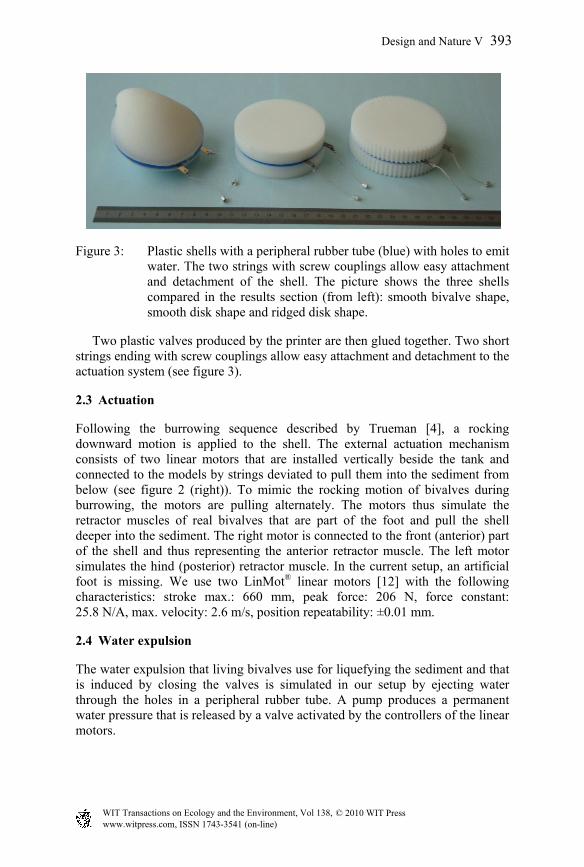
Figure 3: Plastic shells with a peripheral rubber tube (blue) with holes to emit water. The two strings with screw couplings allow easy attachment and detachment of the shell. The picture shows the three shells compared in the results section (from left): smooth bivalve shape, smooth disk shape and ridged disk shape.
Two plastic valves produced by the printer are then glued together. Two short strings ending with screw couplings allow easy attachment and detachment to the actuation system (see figure 3).
2.3 Actuation
Following the burrowing sequence described by Trueman [4], a rocking downward motion is applied to the shell. The external actuation mechanism consists of two linear motors that are installed vertically beside the tank and connected to the models by strings deviated to pull them into the sediment from below (see figure 2 (right)). To mimic the rocking motion of bivalves during burrowing, the motors are pulling alternately. The motors thus simulate the retractor muscles of real bivalves that are part of the foot and pull the shell deeper into the sediment. The right motor is connected to the front (anterior) part of the shell and thus representing the anterior retractor muscle. The left motor simulates the hind (posterior) retractor muscle. In the current setup, an artificial foot is missing. We use two LinMot® linear motors [12] with the following characteristics: stroke max.: 660 mm, peak force: 206 N, force constant: 25.8 N/A, max. velocity: 2.6 m/s, position repeatability: ±0.01 mm.
2.4 Water expulsion
The water expulsion that living bivalves use for liquefying the sediment and that is induced by closing the valves is simulated in our setup by ejecting water through the holes in a peripheral rubber tube. A pump produces a permanent water pressure that is released by a valve activated by the controllers of the linear motors.
www.witpress.com, ISSN 1743-3541 (on-line) WIT Transactions on Ecology and the Environment, Vol 138, © 2010 WIT Press
Design and Nature V 393

2.5 Control
The linear motors are controlled by the software LinMot® Talk. To synchronise the motor motion with the water expulsion, the commands for the water valve are integrated into the controller programs of the motors. A burrowing run contains the following command sequence for the right motor: (a) Go to the starting position and pause. (b) Open the valve for water expulsion and close it again after 100 ms. (c) Pull the shell one step further into the sediment. (d) Pause. (e) Repeat starting at (b). The controller of the left motor does not contain commands for the water expulsion valves, but otherwise executes the same command sequence, offset by a certain time lag. During the pause in (a), the shell is manually put in an erect position above the sediment surface. The size of the burrowing steps in (c) was usually set to a value of 5 or 8 mm. Following the standard way of programming the linear motors, the first kind of controller used position commands to prescribe a burrowing motion that was precisely followed. As this leads to the same burrowing depth for all bivalve models, the force curve was analysed instead. Larger pulling forces for the same motion pattern imply a less efficient shape. A second kind of controller was implemented to better reflect the biological reality. The force for pulling the shell into the sediment was restricted. This allowed for the possibility of a deviation of the actual position from the programmed target position when the penetration resistance was too large.
2.6 Experiments
Using the described setup, several systematic experiments were performed. Many parameters determining the morphology and behaviour of the robot bivalves can be varied, including the overall shell shape, the amount and shape of radial and commarginal sculpture and the timing of the elements of the burrowing cycle. So far, only parameters with a supposedly larger effect have been analysed, namely the overall shape, peripheral ridges, water expulsion and pulling angle. 10 to 20 identical burrowing runs were executed immediately one after the other for one experiment. In order to change only one factor from experiment to experiment, the initial conditions before each burrowing run had to be standardised. In the case of the sediment, a rake was moved to a certain depth and up through the sand to loosen the compacted state from the last run. The sediment height and planarity was established by dragging a metal slat over beams attached to the tank walls. To judge the performance of a particular morphology or burrowing pattern, we consider burrowing depth and the energy used for burrowing most important. Energy cannot be measured directly easily, so we use force. The linear motors provide internal sensors for both position and force (current), therefore we use them to record data about the burrowing performance. The data is logged by LabViewTM [13] and evaluated using Matlab® [14].
www.witpress.com, ISSN 1743-3541 (on-line) WIT Transactions on Ecology and the Environment, Vol 138, © 2010 WIT Press
394 Design and Nature V

3 Results
This section will summarise the results of the experiments. Several sources of error (see discussion) led to fluctuations and made it hard to produce significant results. In all experiments, the right motor had to exert a larger force or moved to a lesser depth than the left motor. This may be due to a slightly shorter right string. Force values are consequently only compared for either of the motors but not between the motors. In comparisons we consider morphologies or configurations to be “better” if they lead to a larger burrowing depth or to smaller pulling forces.
3.1 Data
As the strings are always straight, the position of the motor sliders is taken to reflect the burrowing depth. The force exerted by the motors is proportional to the current, so we compute the force necessary for burrowing by multiplying the force by the motor specific force factor and adding the weight of the sliders, as the motors are placed vertically. These computations are already done by LabViewTM. The resulting data record for a single burrowing experiment consists of a series of triplets (ti, fi, xi), i.e. time, force and position, respectively. Usually, 20 ms are used as measurement time intervals, values between 10 and 100 ms are possible. The sensors sometimes produce faulty values (values outside the range of physically possible values). We filter the data as follows: invalid positions are replaced by the linear interpolation between the next valid neighbouring values; we cannot drop these values entirely, because the number of data points has to be consistent with the other data sets for further evaluation; extreme values like burrowing depths, however do not change by this procedure. Invalid forces are replaced by NaN and ignored for the evaluation. Gaps in the time sequence are completed by the same means (linear interpolation and inserting NaN). The average fractions of invalid data are roughly 2% for positions and 5% for forces. Gaps make up 3% of the data.
3.2 Comparison of shapes
Until now, we mainly tested the three disk-related shapes shown in figure 3, i.e. a smooth bivalve shape, a smooth disk shape and a ridged disk shape (shaped like a cogwheel). The diameters of the disks and of the aperture of the bivalve shape are equal. Also, the masses are almost the same. Differences in burrowing performance of the three models should therefore reflect the differences in shape. The bivalve shape does not represent any particular living species. It is artificially designed to be similar to the disk shapes but is generated using the shell generation method described earlier. The wavelength of the ridges of one of the disk shells is 4 mm, the peak-to-peak amplitude 2 mm. Using the position control program, the pulling forces shown in figure 4 were measured. The top graph shows the pulling force applied during one burrowing run. As the model is pulled deeper into the sediment, the force increases. The periodic steps in the curve correspond to the burrowing cycles. The bottom graph
www.witpress.com, ISSN 1743-3541 (on-line) WIT Transactions on Ecology and the Environment, Vol 138, © 2010 WIT Press
Design and Nature V 395

Figure 4: (Top) The pulling force of the right motor for the smooth disk shell, water expulsion deactivated. Shown is the median (black), the 25% and 75% (dark area) and the 2.5% and 97.5% quantiles. (Bottom) The mean pulling forces exerted by the right motors for the three shapes, water expulsion activated. Each curve is computed from 20 burrowing experiments. A curve has roughly the shape of a step function with 12 steps that correspond to the burrowing cycles.
396 Design and Nature V
www.witpress.com, ISSN 1743-3541 (on-line) WIT Transactions on Ecology and the Environment, Vol 138, © 2010 WIT Press
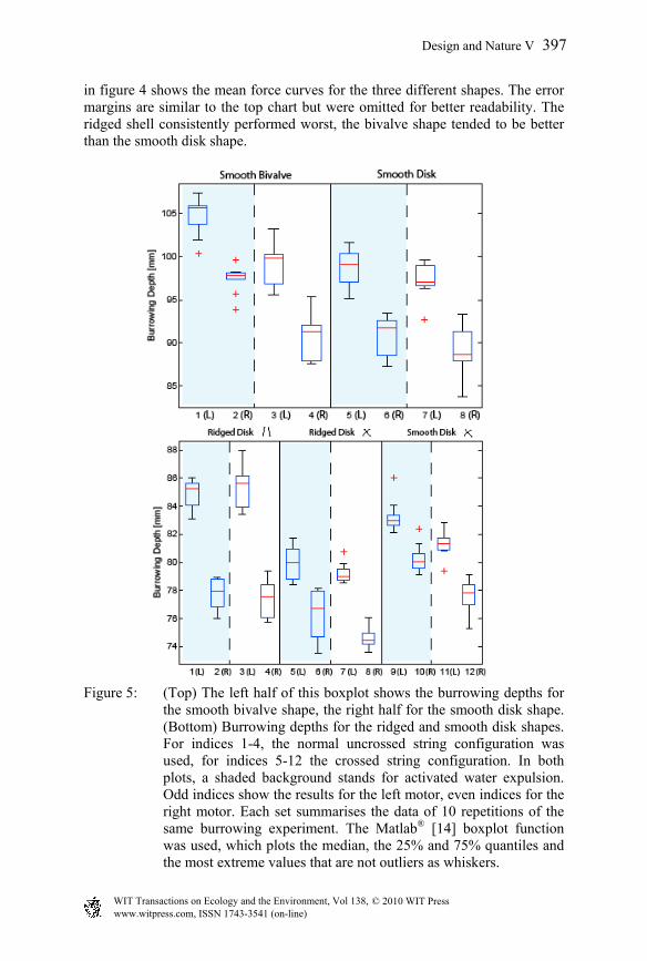
in figure 4 shows the mean force curves for the three different shapes. The error margins are similar to the top chart but were omitted for better readability. The ridged shell consistently performed worst, the bivalve shape tended to be better than the smooth disk shape.
Figure 5: (Top) The left half of this boxplot shows the burrowing depths for the smooth bivalve shape, the right half for the smooth disk shape. (Bottom) Burrowing depths for the ridged and smooth disk shapes. For indices 1-4, the normal uncrossed string configuration was used, for indices 5-12 the crossed string configuration. In both plots, a shaded background stands for activated water expulsion. Odd indices show the results for the left motor, even indices for the right motor. Each set summarises the data of 10 repetitions of the same burrowing experiment. The Matlab® [14] boxplot function was used, which plots the median, the 25% and 75% quantiles and the most extreme values that are not outliers as whiskers.
www.witpress.com, ISSN 1743-3541 (on-line) WIT Transactions on Ecology and the Environment, Vol 138, © 2010 WIT Press
Design and Nature V 397

3.3 Water expulsion
Figure 5 (top) shows a boxplot of the burrowing depths reached with different configurations and the force control program. As already mentioned, there is a difference between the depth reached by the left and the right motor. Additionally, the burrowing runs using water expulsion usually penetrate deeper. The effect is not always present, but positive if it is. In the bivalve case it seems to be rather significant, while in the disk case in this graph, there is only a small difference.
3.4 Pulling angle
In bivalve burrowing, the rotation angle induced by the retractor muscles is often adjusted to the sculpture and influences burrowing performance. By altering the pulling direction of the strings, we can change the amount of rotation in our setup. Therefore we tested two different configurations. The setting provides three different pairs of strings of which we used the outmost one, where the holes in the bottom plate are at a distance of 112 mm. In the second configuration, the same string pair was used in a crossed way, i.e. the shell was rotated around the vertical axis by 180°. In the uncrossed setting, the strings pull the anterior attachment site forward at an angle of 8° to the vertical line, in the crossed setting they pull it backward at 14°. As the second setting implies a more tangential pulling direction, it leads to a bigger rotation.
Figure 6: Comparison in burrowing depth of the ridged and smooth disk
shells with crossed and uncrossed string configurations. A part of the mean curves for the right motor are shown. Confidence intervals do overlap and are not shown for a better readability. Each mean is computed from 10 data sets, the quantiles in figure 5 (bottom) give an estimation of the respective curve variances.
www.witpress.com, ISSN 1743-3541 (on-line) WIT Transactions on Ecology and the Environment, Vol 138, © 2010 WIT Press
398 Design and Nature V

See figure 5 (bottom) for a comparison of the two configurations. Figure 6, however, shows that the ranking is not constant throughout the burrowing process.
4 Discussion
4.1 Morphology
According to the data collected so far, the bivalve shape is better suited for burrowing than its crudest approximation, a disk. We did not expect the ridged shape to perform worse than the other two. As sculpture amplitude and grain size are correlated in nature, further experiments using different amplitudes and grain sizes should investigate this issue. Sculpture also has the function of preventing the bivalve from being excavated by water current and buoyancy effects. This cannot be tested easily with the current approach because the strings do not allow the shell to move upwards.
4.2 Water expulsion
The current method of simulating the water expulsion does not capture an important aspect of the real mechanism: when closing the valves, bivalves do not only eject water, but the shell contraction itself also makes room for liquefied sediment around it. In the presented experiments, water expulsion was less effective than first test results suggested. This may be due to a design change we made: to avoid the tube holes being blocked by sand grains, we reduced the diameter of the holes below the grain size while increasing the number of holes. It is also possible, that the lack of shell contraction limits the effect because the ejection is not strong enough to displace the compacted sediment around the shell. Future improvements of the shell models including an opening and closing mechanism may shed light on this issue.
4.3 Position control and force control
The controllers prescribing the position were easier to program and to handle, because they correspond to the manner how these industrial motors are normally used. The second kind of controllers that limited the forces, however, turned out to produce more realistic simulations. The increasingly smaller burrowing steps reflect the way natural bivalves burrow much better. The force that bivalve muscles can exert is also limited and probably determines how far it moves in a burrowing cycle. While the force curves in figure 4 are hard to interpret, depth curves like in figure 6 are more readable.
4.4 Pulling angle
Figures 5 (bottom) and 6 show again, that the smooth disk outperforms the ridged disk. However, the second figure shows in addition, that the ranking of
www.witpress.com, ISSN 1743-3541 (on-line) WIT Transactions on Ecology and the Environment, Vol 138, © 2010 WIT Press
Design and Nature V 399

the ridged shell is not stable with respect to the crossed and uncrossed configurations. The uncrossed version (smaller rotation angle) is worse a long time until it finally surpasses the crossed version (larger rotation angle). An explanation may be that initially, a large rotation has a similar effect as water expulsion, loosening the sediment and thus reducing penetration resistance. As the shell gets deeper into the sediment and the motion more restricted due to larger friction, this effect is weakened. In this later phase, direct pulling may thus become more effective.
4.5 Sensor data
As the force is measured indirectly by the current consumed by the motors, it is subject to peaks and fluctuations in the control circuit. The forces react sensitively to small resistance disturbances in order to execute the control program with high precision. This type of fluctuation is not reproducible. The positions measured by the motors do not reflect the actual burrowing depth perfectly. The length of the strings expands on average by 1.5 mm per kilogram and metre. Also the metal parts the setup is made of do slightly bend. The strings are connected by knots that may tighten slightly when higher forces are applied.
4.6 Sediment
An error source that is hard to handle is the configuration of the sediment. The spatial distribution of grain sizes and the state of compaction are different for every experiment run. The state of compaction of the sediment seems to have a large effect on the burrowing performance. The introduction of a rake for a deeper and more systematic sediment perturbation before a burrowing run increased the burrowing performance of the shells markedly. In order to produce more reliable and less noisy data, an automated standardisation technique should be implemented. Abrasion of the plastic shells by the sand could not be detected yet. After more than 100 burrowing runs, the front ridges of the ridged disk shell are still intact.
5 Future work
Although the evaluation of the experiments led to interesting insights into the burrowing mechanism of bivalves and how it may be simulated, the setup has to be improved further to produce more reliable and significant data. It should, e.g. be ensured that the strings are of the same length. As natural bivalves often burrow in a direction lying between anterior and ventral, a shorter right string does not contradict the conditions found in nature, but it makes data evaluation more difficult. The current geometric model can only produce mixtures of radial and commarginal surface sculpture. As certain types of skew sculpture are considered beneficial for burrowing, they should be integrated into the model.
www.witpress.com, ISSN 1743-3541 (on-line) WIT Transactions on Ecology and the Environment, Vol 138, © 2010 WIT Press
400 Design and Nature V

To overcome the limitations of using only the internal sensors of the motors, we are building shells containing additional force sensors. Optical tracking of the shells will allow more precise burrowing depth measurements and in addition the possibility to also capture the orientation of the shell. Measuring depth and forces redundantly will lead to more precise data, hopefully enabling us to compare differences surface sculptures. Once morphological changes are expressed in burrowing performance reliably, we will apply the control of an artificial evolutionary system to evolve interesting shapes and shed light on palaeontological questions. Specific recent or fossil specimens may be tested in sediment by using a computed tomography (CT) scanner to generate virtual 3D models and printing them by the 3D printer. Burrowing performance tests in different sediment types may shed light on the mode of life of species with previously unclear habitat. To further improve and expand the robotic platform, the water expulsion mechanism using rubber tubes will be replaced by and compared to an artificial bivalve featuring a mechanism for opening and closing the valves. The final goal is to construct a mechanically autonomous burrowing robot by adding an artificial foot.
Acknowledgements
Many thanks to A. Koller-Hodac, K. Dietrich, A. Gilgen and P. Brändli from the University of Applied Sciences in Rapperswil (HSR) for their competent contribution in building the setup. We also thank R. Pfeifer, R. Füchslin, M. Hadorn and the other members of the AIlab for their support and the Swiss National Science Foundation for funding the project.
References
[1] Raup D. and Michelson A., Theoretical Morphology of the Coiled Shell, Science, Vol. 147, pp. 1294-1295, 1965.
[2] Fowler D.R., Meinhardt H. and Prusinkiewicz P., Modeling seashells, Computer Graphics, Vol. 26, pp. 379-387, 1992.
[3] Hammer O. and Bucher H., Models for the morphogenesis of the molluscan shell, Lethaia, Vol. 38, pp. 111-122, 2005.
[4] Trueman E.R., Bivalve Mollusks: Fluid Dynamics of Burrowing, Science, New Series, Vol. 152, No. 3721, pp. 523-525, 1966.
[5] Stanley S.M., Why clams have the shape they have: an experimental analysis of burrowing, Paleobiology, Vol. 1, No. 1, pp. 48-58, 1975.
[6] Stanley S.M., Bivalve Mollusk Burrowing Aided by Discordant Shell Ornamentation, Science, Vol. 166, pp. 634-635, 1969.
[7] Savazzi E. and Pan H., Experiments on the frictional properties of terrace sculptures, Lethaia, Vol. 27, pp. 325-336, 1994.
[8] Winter A.G., Hosoi A.E., Slocum A.H. and Deits R.L.H., The Design and Testing of RoboClam: A Machine Used to Investigate and Optimize Razor
www.witpress.com, ISSN 1743-3541 (on-line) WIT Transactions on Ecology and the Environment, Vol 138, © 2010 WIT Press
Design and Nature V 401
Clam-Inspired Burrowing Mechanisms for Engineering Applications, Proceedings of the ASME 2009 International Design Engineering Technical Conferences & Computers and Information in Engineering Conference, IDETC/CIE, 2009.
[9] Trimmer B.A., Takesian A.E., Sweet B.M., Rogers C.B., Hake D.C. and Rogers D.J., Caterpillar locomotion, a new model for soft-bodied climbing and burrowing robots, Proceedings of the 7th International Symposium on Technology and the Mine Problem, Monterey, 2006.
[10] Koller-Hodac A., Germann D.P., Gilgen A., Dietrich K., Hadorn M., Schatz W. and Eggenberger Hotz P., Actuated Bivalve Robot – Study of the Burrowing Locomotion in Sediment, IEEE International Conference of Robotics and Automation (ICRA 2010), in press, 2010.
[11] Dimension® 3D printer, model bst 768; CatalystEx, Version 4.0.1, Stratasys Inc.; www.dimensionprinting.com
[12] LinMot® linear motors, P01-37x240F/460x660-C; LinMot Talk1100-V3.9, NTI AG; www.linmot.com
[13] LabView™, Version 8.6, National Instruments, www.ni.com/labview /optin/
[14] Matlab®, Version R2009b, The MathWorks Inc., www.mathworks.com
www.witpress.com, ISSN 1743-3541 (on-line) WIT Transactions on Ecology and the Environment, Vol 138, © 2010 WIT Press
402 Design and Nature V