blackjax 5 - directeddealers.com · 2 bitwriter®, code hopping™, directed®, doubleguard ®,...
TRANSCRIPT

© 2005 Directed Electronics, Vista, CA N909505 10-05
BBllaacckkJJaaxx 55➤IInnssttaallllaattiioonn GGuuiiddee

www.directed.com2
Bitwriter®, Code Hopping™, Directed®, Doubleguard®, ESP™, FailSafe®, Ghost Switch™, Learn Routine™, Nite-Lite®, Nuisance Prevention® Circuitry, NPC®, Revenger®, Silent Mode™, Soft Chirp®, Stinger®, Valet®, VehicleRecovery System®, VRS®, and Warn Away® are all Trademarks or Registered Trademarks of Directed Electronics,Vista, California.
© 2005 directed electronics—all rights reserved 3
warning! safety first . . . . . . . . . . .5
standard features . . . . . . . . . . . . .5
what’s included . . . . . . . . . . . . . . .5before beginning the installation 6
h1 harness wire connection guide 7h1 harness wiring diagram . . . .7h1 harness wiring guide . . . . . .7h1 heavy gauge harness wiring guide . . . . . . . . . . . . . . .7
h2 harness wire connection guide 8h2 harness wiring diagram . . . .8h2 harness wiring guide . . . . . .8
H2/3–white plainview 2 valet
switch . . . . . . . . . . . . . . . . . . . . . . .8
H2/4–yellow (-) siren . . . . . . . . . . .8
blackjax installation . . . . . . . . . . .9control unit . . . . . . . . . . . . . . . .9ignition immobilizer . . . . . . . . .10starter immobilizer . . . . . . . . . .10LED status indicator . . . . . . . . .10plainview 2 coded valet switch 11
driver’s door trigger . . . . . . . . .11brake lights . . . . . . . . . . . . . . .11siren . . . . . . . . . . . . . . . . . . . .12horn connection (option) . . . . .12tachometer connection . . . . . .12speed connection . . . . . . . . . .13final wiring connections . . . . . .13
rpm/speed programming . . . . . .14RPM programming procedure .14speed programming procedure 15
programmable features . . . . . . .16using the CliffordWizard Proinstallation software . . . . . . . .16programming the user-selectablefeatures using the PlainView 2switch . . . . . . . . . . . . . . . . . . .16
system check/troubleshooting . .18
wiring reference section . . . . . . .20h2 connector . . . . . . . . . . . . . .21
notes . . . . . . . . . . . . . . . . . . . . . . .22
contents

www.directed.com4

© 2005 directed electronics—all rights reserved 5
UUKK rreessiiddeennttss:: Please excuse our American English. Hood means bonnet, parking lightsare indicator lights, and gasoline is petrol.
warning! safety firstThe following safety warnings must be observed at all times:
Due to the complexity of this system, installation of this product must only be per-formed by an authorized Directed dealer.
Use of this product in a manner contrary to its intended mode of operation mayresult in property damage, personal injury, or death.
standard featuresHigh Output Siren
Two-Point Immobilization
Programmable Passive Immobilization
Programmable Siren/Horn Output
Programmable Siren Duration
what’s includedBlackJax Module 514C High Output Siren
PlainView 2 Valet switch 10-Pin Wire Harness
LED Status indicator 4-Pin Heavy Gauge Wire Harness
www.directed.com6
before beginning the installation
Please read this entire installation guide before beginning the installation. Theinstallation of this system requires interfacing with many of the vehicle’s systems.Many new vehicles use low-voltage or multiplexed systems that can be damagedby low resistance testing devices, such as test lights and logic probes (computersafe test lights). Test all circuits with a high quality digital multi-meter before mak-ing connections.
Do not disconnect the battery if the vehicle has an anti-theft-coded radio. Ifequipped with an air bag, avoid disconnecting the battery if possible. Manyairbag systems will display a diagnostic code through their warning lights afterthey lose power. Disconnecting the battery requires this code to be erased, whichcan require a trip to the dealer.
Remove the domelight fuse. This prevents accidentally draining the battery.
Roll down a window to avoid being locked out of the car.
after the installation
Test all functions. Refer to the "Using Your System" section of the Owner's Guidewhen testing.
Complete a vehicle safety check prior to reassembly. Ensure all vehicle systemsare operational (same condition as-found prior to installation).
© 2005 directed electronics—all rights reserved 7
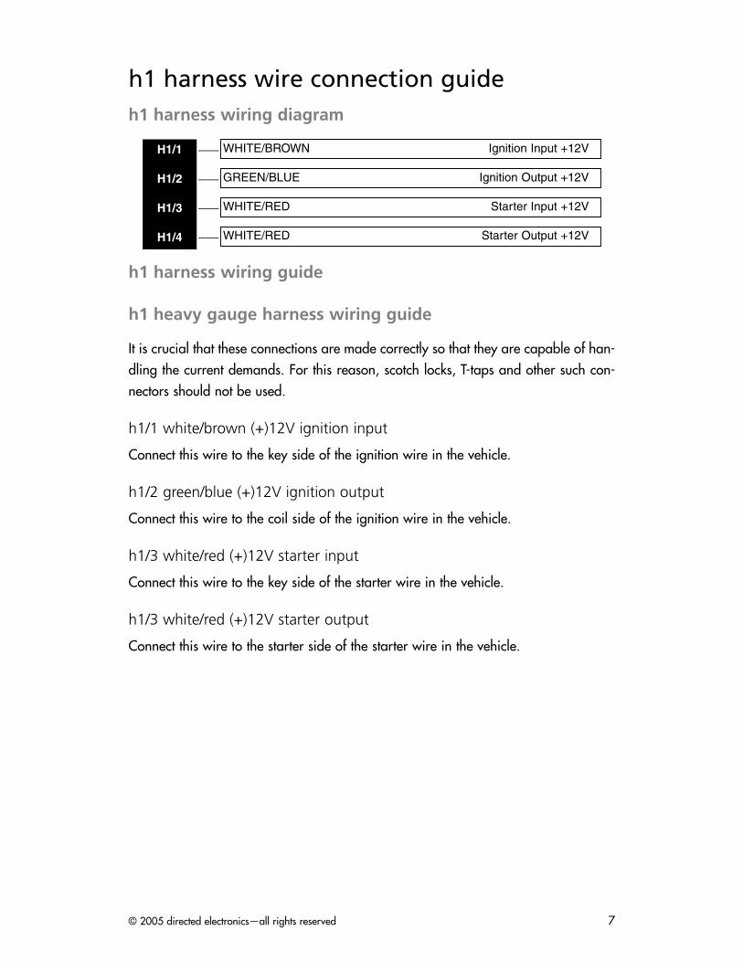
h1 harness wire connection guideh1 harness wiring diagram
___
___
___
___
h1 harness wiring guide
h1 heavy gauge harness wiring guide
It is crucial that these connections are made correctly so that they are capable of han-dling the current demands. For this reason, scotch locks, T-taps and other such con-nectors should not be used.
h1/1 white/brown (+)12V ignition input
Connect this wire to the key side of the ignition wire in the vehicle.
h1/2 green/blue (+)12V ignition output
Connect this wire to the coil side of the ignition wire in the vehicle.
h1/3 white/red (+)12V starter input
Connect this wire to the key side of the starter wire in the vehicle.
h1/3 white/red (+)12V starter output
Connect this wire to the starter side of the starter wire in the vehicle.
WHITE/RED Starter Output +12V
WHITE/RED Starter Input +12V
GREEN/BLUE Ignition Output +12V
WHITE/BROWN Ignition Input +12VH1/1
H1/2
H1/3
H1/4

www.directed.com8
h2 harness wire connection guideh2 harness wiring diagram
___
___
___
___
___
___
___
___
___
___
h2 harness wiring guide
H2/1–green (-) armed out
Connects to an accessory such as a 620C EL Indicator, pager or can be used as athird Immobilisation output by adding a relay.
H2/2–gray (+) or (-) door trigger
Connects to door pin switch. Factory default is set for negative door trigger. If positivedoor trigger is required, the positive trigger feature will have to be programmed.
H2/3–white plainview 2 valet switch
Connects to plainview 2 valet switch.
H2/4–yellow (-) siren
Connect this wire to the Black wire coming from the siren. Can optionally be used asa horn output.
NNOOTTEE:: The H2/4 (Yellow) wire is capable of supplying 2-amps.
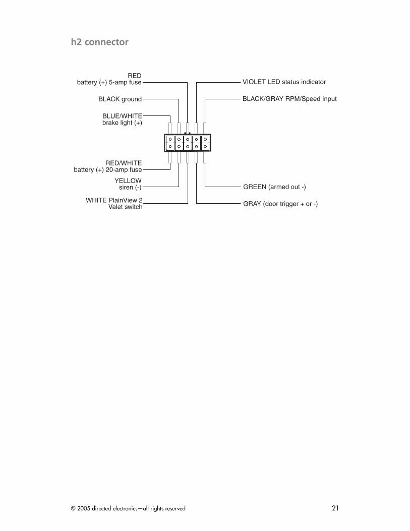
BLUE/WHITE Brake Light Input (+)
BLACK Ground (-)
RED Battery Positive (5-amp fuse) 12V (+) Input
VIOLET Status LED (+)
BLACK/GRAY RPM/Speed Input (-)
RED/WHITE Battery Positive (20-amp fuse) 12V (+) Input
YELLOW Siren (-)
WHITE PlainView 2 Valet Switch
GRAY Door Trigger (+) or (-)
GREEN Armed Out (-)H2/1
H2/2
H2/3
H2/4
H2/5
H2/6
H2/7
H2/8
H2/9
H2/10

© 2005 directed electronics—all rights reserved 9
H2/5–red/white battery positive (20-amp fuse) 12V (+) input
Connects to the vehicle’s positive battery terminal using the 20-amp fuse holder.
H2/6–black/gray (-) rpm input
This wire monitors the RPM of the vehicle by the BlackJax control. Connect this wireto the vehicle coil’s negative side or the non-common fuel injector wire.
H2/7–violet system status LED
Connects to the Status LED indicator.
H2/8–red battery positive (5-amp fuse) 12V (+) input
Connects to the vehicle’s positive battery terminal using the 5-amp fuse holder.
H2/9–black (-) ground
H2/10–blue/white (+) brake light input/output
Connects to the brake light circuit. This initiates BlackJax countdown to activation aftera door has been opened/closed. Also when BlackJax is activated, it flashes the brakelights to warn motorists behind the vehicle.
blackjax installation
IIMMPPOORRTTAANNTT!! Do not use any testing tool other than a digital multi-meter to preventcostly damage to the vehicle. Use of a test light may cause grounding of sensitive elec-trical components that can damage the on-board vehicle computer and processorsresulting in substantial cost for replacement.
control unit
Select an area behind the dash to mount the control unit, but do not permanently affixit until all wiring and testing is complete.

www.directed.com10
ignition immobilizer
1. Use a voltmeter to locate the wire that is 0 volts when the ignition is “OFF” andcarries +12V throughout BOTH the starting/cranking and engine running cycles.With the engine running, cut this wire. The car’s engine should stop running.
2. Connect the WHITE/BROWN wire to the key side of the ignition wire and theGREEN/BLUE wire to the coil side.
starter immobilizer
The starter immobilizer ensures the engine will not crank when BlackJax anti-carjackmode is active.
1. Use a voltmeter to locate the one wire that carries +12V during the crankingcycle ONLY. This is the starter wire.
2. Cut the starter wire, then try to start the engine. If the starter does not crank, youhave found the correct wire.
3. Connect the WHITE/RED to the key side and the other WHITE/RED to the starter side.
LED status indicator
Select a prominent location on the dash or console visible through all windows.Discuss placement with the owner.
NNOOTTEE:: The LED can be top-mounted or flush-mounted. If top-mounting the LED with abezel, the LED fits into a 5/16-inch mounting hole. If flush-mounting the LED from the backof a panel, drill a mounting hole using a 17/64-inch drill bit. Be sure to check for clear-ance prior to drilling the mounting hole.
1. Verify there is adequate space and clearance behind the panel to accommodatethe LED, then drill a 5/16” (8mm) hole and route the wires through it.
2. Mate the LED connectors to the VIOLET and BLACK wire connectors as shown inthe wiring diagram in this guide.
3. Press the LED into place.
warning! On vehicles with air bags or supplementalrestraint systems (SRS) you may notice a bright yellowtube with small wires in it marked SRS underneath thesteering column near the key cylinder. DO NOT tamp-er or unplug these for any reason to prevent costly dam-ages to your vehicle or personal injury. Tampering maycause unintended deployment of airbags.

© 2005 directed electronics—all rights reserved 11
plainview 2 coded valet switch
The PlainView 2 switch does not need to be hidden. Rather, it should be mounted onthe dashboard or console within easy and convenient reach of the driver. Discussplacement of the switch with the vehicle owner prior to installation.
NNOOTTEE:: Be sure to check for clearance behind the dashboard or console prior to drilling.
1. Drill a 9/32-inch hole to mount the switch.
2. Route the wires and connectors through the hole and secure the switch.
3. Mate the switch connector to the small connector on the wireloom, noting thewire colors.
driver’s door trigger
This connection is necessary to initiate the BlackJax countdown. The factory defaultsetting is negative door trigger. If positive door trigger is required (on Rolls-Royce andsome Ford vehicles), then refer to the features programming section of this manual.
1. Locate the wire coming off the rear of the vehicle’s door switch.
2. Connect the negative voltmeter lead to ground.
3. Find the one wire that shows (+)12V when the switch is pressed in and 0V whenreleased. This is a negative door trigger wire. If you do not find this wirecontinue to the next step, else proceed to step 5.
4. Find the one wire that shows 0V when the switch is pressed in and 12V whenreleased. This is a positive door trigger wire. The Features Programming willhave to be set for positive door trigger (discussed later in this manual).
5. Connect the control unit’s GRAY wire to this door trigger wire.
NNOOTTEE:: DirectTechs web site (www.directechs.com) for authorized Directed dealershas detailed descriptions of wire colors and locations for most foreign and domesticvehicles.
brake lights
For safety reasons, BlackJax is wired to the brake light rather than the parking lights.Also, pressing the brake after the door has been opened/closed starts the BlackJaxcountdown. When BlackJax is activated, the flashing brake lights will warn motoriststhat are driving behind the carjacked vehicle.

www.directed.com12
1. Turn the ignition on and press the brake pedal to make sure the brake lightilluminates.
2. Connect the black lead of the voltmeter to ground and set the dial to DC volts.
3. Probe the wires at the brake light switch with the voltmeter. The voltmeter shouldread +12V when you press the brake pedal; 0 volts when released.
4. Connect the BLUE/WHITE wire to the brake wire.
siren
Mount the siren in the engine compartment away from moving or heat-producingcomponents. Mount the siren in the engine compartment on the opposite side from theexhaust manifold. The siren must not be accessible or visible from outside or under thevehicle. Point the siren downward to avoid water collection and enhance sound pro-jection.
1. Mount the siren using all three sheet metal screws supplied.
2. Connect the siren’s BLACK wire to the control unit’s YELLOW wire.
3. Connect the siren’s RED wire to the control unit’s RED wire.
horn connection (option)
If you choose not to use the standard siren, the yellow wire can be programmed as ahorn output (refer to Features Programming in this manual) and can be connected tothe vehicle’s horn. This output is negative and can provide up to 2 amps.
tachometer connection
Some newer vehicles do not have a conventional ignition coil marked (+) and (-). Inthese instances, you will need to locate the tach wire:
1. Try to locate the distributor cap which all spark plug wires run into. There shouldbe the same number of plug wires as the number of cylinders. If there is an extraplug wire, the vehicle has a separate coil.
2. Follow the extra plug wire to the coil module, which will have two or more wires.
a. If there are only two wires: one is the ignition, the other wire is the negativecoil wire. Connect the Black/Gray wire from the control module to thenegative coil wire.
© 2005 directed electronics—all rights reserved 13
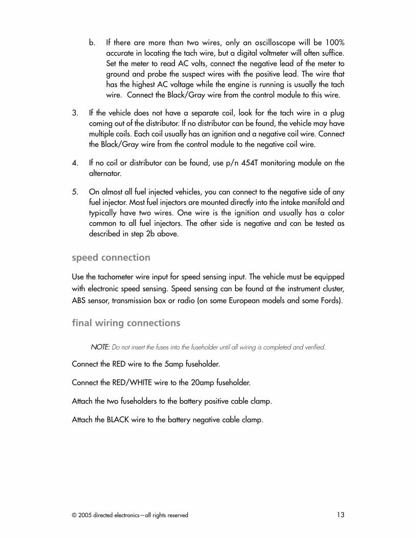
b. If there are more than two wires, only an oscilloscope will be 100%accurate in locating the tach wire, but a digital voltmeter will often suffice.Set the meter to read AC volts, connect the negative lead of the meter toground and probe the suspect wires with the positive lead. The wire thathas the highest AC voltage while the engine is running is usually the tachwire. Connect the Black/Gray wire from the control module to this wire.
3. If the vehicle does not have a separate coil, look for the tach wire in a plugcoming out of the distributor. If no distributor can be found, the vehicle may havemultiple coils. Each coil usually has an ignition and a negative coil wire. Connectthe Black/Gray wire from the control module to the negative coil wire.
4. If no coil or distributor can be found, use p/n 454T monitoring module on thealternator.
5. On almost all fuel injected vehicles, you can connect to the negative side of anyfuel injector. Most fuel injectors are mounted directly into the intake manifold andtypically have two wires. One wire is the ignition and usually has a colorcommon to all fuel injectors. The other side is negative and can be tested asdescribed in step 2b above.
speed connection
Use the tachometer wire input for speed sensing input. The vehicle must be equippedwith electronic speed sensing. Speed sensing can be found at the instrument cluster,ABS sensor, transmission box or radio (on some European models and some Fords).
final wiring connections
NNOOTTEE:: Do not insert the fuses into the fuseholder until all wiring is completed and verified.
Connect the RED wire to the 5amp fuseholder.
Connect the RED/WHITE wire to the 20amp fuseholder.
Attach the two fuseholders to the battery positive cable clamp.
Attach the BLACK wire to the battery negative cable clamp.

www.directed.com14
rpm/speed programming
NNOOTTEE:: Upon completion of the installation, and if a tach or speed sense connectionhas been made, one of the two following programming steps mmuusstt be done. TheBlackJax 5 module has the default sense mode set to tach.
The BlackJax 5 is versatile in that it has the ability to work with tachometer, or speedsense, or no sense connection at all.
In ssppeeeedd sseennssee mode, the ignition will shut off at or below the programmed speed. Thevehicle must be equipped with electronic speed sense.
In ttaacchh sseennssee mode, the ignition will shut off at or below the programmed RPM.
With nnoo ssppeeeedd oorr ttaacchh connection, the ignition will not shut off. Instead, BlackJax 5will not allow the vehicle to restart once the ignition has been turned off.
RPM programming procedure
NNOOTTEE:: This programming step mmuusstt be completed if the tach is connected for theBlackJax 5 to operate properly.
1. Drive the vehicle to a nearby open area and allow the engine to warm-up untilthe RPMs drop to the normal idle speed.
2. With the engine still running, place the transmission in PARK (or NEUTRAL if thevehicle has a manual transmission).
3. Enter installer-programming mode (with the ignition ON, enter the factory presetvalet code by pressing the button twice and the button once, then pressand hold the button for 13 seconds). Within the first 3-seconds, you will hearone chirp. Continue holding the button until you hear three chirps - thisindicates that you are now in installer programming mode. Release the button.
4. Press the button of the PlainView 2 Switch once. After a 3-second pause, thesystem will sound one chirp to confirm column one selection (see the Installer-Programmable Features section).
5. Press the button of the PlainView 2 Switch five times (you will hear a chirpeach time you press the button) to select row five. After a 2-second pause, youwill hear two chirps to confirm idle RPM has been set (if you hear just one chirp,check the connection of the BLACK/GRAY wire, then repeat steps 1–5).
6. Turn the ignition OFF.

© 2005 directed electronics—all rights reserved 15
speed programming procedure
NNOOTTEE:: This programming step mmuusstt be completed if the speed sense setting is usedfor the BlackJax 5 to operate properly.
to change read mode from tach to speed
1. Turn the ignition ON.
2. Enter installer programming mode (with the ignition ON, enter the factory presetvalet code by pressing the button twice and the button once, then pressand hold the button for 13 seconds). Within the first 3-seconds, you will hearone chirp. Continue holding the button until you hear three chirps - thisindicates that you are now in installer programming mode. Release the button.
3. Press the button of the PlainView 2 Switch once. After a 3-second pause,the system will sound one chirp to confirm column one selection (see the Installer-Programmable Features section).
4. Press the button of the PlainView 2 Switch twice (you will hear a chirp eachtime you press the button) to select row two. After a 2-second pause, you willhear one chirp indicating you are now in speed sense mode.
to set speed
1. Determine what the ideal speed will be for the vehicle's ignition to shut off.
2. Drive the vehicle to an open area or a local surface street.
3. Enter installer programming mode (with the ignition ON, enter the factory presetvalet code by pressing the button twice and the button once, then pressand hold the button for 13 seconds). Within the first 3-seconds, you will hearone chirp. Continue holding the button until you hear three chirps - thisindicates that you are now in installer programming mode. Release the button.
4. Drive the vehicle to the desired minimum speed you would like the ignition toshut off when BlackJax 5 initiates.
WWAARRNNIINNGG!! There mmuusstt be another technician in the carto program the MPH while the vehicle is being driven, orinjury or death could result.
www.directed.com16
5. Press the button of the PlainView 2 Switch once. After a 3-second pause, thesystem will sound one chirp to confirm column one selection (see the Installer-Programmable Features section).
6. Press the button of the PlainView 2 Switch five times (you will hear a chirpeach time you press the button) to select row five. After a 2-second pause, youwill hear either one or two chirps.
11 cchhiirrpp Indicates that the system has properly learned 0 MPH or; if the system wasprogrammed at more than 0 MPH, 1 chirp indicates that there was a faultreading the speed sense input (check the connection on the BLACK/GRAY wire,then repeat steps 1 - 5).
22 cchhiirrppss Confirms the speed has been set.
programmable featuresBlackJax 5 comes from the factory with its features preprogrammed as noted in boldletters in the following tables. Some features can be programmed by the installer orthe user, others can only be programmed by the installer. There are two tables provid-ed which define the user-programmable and installer-programmable features.
using the CliffordWizard Pro installation software
Cliffnet Wizard Pro provides access to all available system features and some that arenot available when manually programming with the Valet switch. Cliffnet Wizard Pro iscompatible with Microsoft Windows 95/98/2000/ME/XP/NT so most programmingoperations can be accomplished by pointing and clicking with a mouse. This eliminatesthe need for programming grids and lengthy programming sequences. For a completeguide to system programming using the Cliffnet Wizard Pro refer to the Cliffnet Wizardhelp menu. Otherwise, refer to the tables provided in the following sections.
programming the user-selectable features using thePlainView 2 switch
1. Write down the column (across) number and row (down) number of thefeature(s) you wish to program.
2. Turn the ignition to the “ON” position or start the engine.
3. Enter the factory preset valet/programming code of “2” by pressing the button twice, and then pressing the button once.

© 2005 directed electronics—all rights reserved 17
4. After entering the code, press and hold the for about 3 seconds until youhear one siren chirp and the LED turns on to acknowledge program mode entry.The system is now in the “Feature Select” position for User-ProgrammableFeatures.
5. Select the feature column: Press the unmarked button once. Pause. You will thenhear one chirp.
6. Within five seconds, select the feature row: Press and release the button thesame number of times as the feature’s row number. You’ll hear a chirp each timeyou press the unmarked side to help you count.
7. If there is a NOTE for the selected feature, perform the actions noted.
8. Pause. You will hear either one or two chirps: Two chirps = ON, one chirp = OFF.
9. You can select another feature, or you can exit program mode:
a. To start over, repeat step 6 within the next five seconds (after five seconds,three chirps indicat e that the system is now back in the “Feature Select”position).
b. To select a different feature column, repeat step 5.
c. To exit program mode, turn the ignition off (you’ll hear three chirps and theLED will turn off to indicate exit of program mode), or wait 60 seconds andthe system will automatically exit program mode.
For example: while the ignition is “ON,” choose the feature you want to change andenter program mode. Select the feature’s column and row, wait for the on/off chirpconfirmation, then turn off the ignition
user-programmable features (1 chirp=off, 2 chirps=on)
Feature Select Description
*1 Not used
*2 Not used
*3 Not used
*4 Siren duration (3300/60/90) (11 cchhiirrpp/2 chirps/3chirps)
*5 Not used
*6 Passive Immobilization (On/OOffff)
*7 Valet Code–should only be programmed by vehicle owner

www.directed.com18
installer-programmable features (1 chirp=off, 2 chirps=on)
To access the installer-programmable features, follow the programming steps 1-4 onthe previous page and then continue to hold the button for 10 seconds until youhear three chirps.
system check/troubleshooting1. Start the car.
2. Open and close the door.
3. Press/release the brake.
Wait 25 seconds. You should hear 5 chirps. If not, go to step 1 below.
The brake lights will begin flashing. If not, go to step 2 below.
30 seconds later, the siren should sound and car’s engine should die if theengine is at or below the programmed RPM or speed level. If not, go to step3 below.
Once the car is disabled, enter the valet code to disarm. If the system doesnot disarm, go to step 4 below.
SStteepp 11 - BlackJax not initializing
1. Check the door trigger connection and polarity.
2. Check the brake trigger.
SStteepp 22 - Brake lights not flashing
1. Check brake light connection.
2. Check to make sure that the 20 amp fuse on the RED/WHITE wire is OK.
Feature Select Description
*1 Not used
*2 Program Speed (see Speed Programming)
*3 Not used
*4 Door Trigger Polarity (NNeeggaattiivvee/Positive) (11 cchhiirrpp/2 chirps)
*5 Program RPM (see RPM Programming)
*6 Auxiliary Siren Output (Constant/PPuullsseedd) (1 chirp/22 cchhiirrppss)
© 2005 directed electronics—all rights reserved 19
SStteepp 33 - Car’s engine does not die.
1. Unplug the large 4-pin Molex connector while the car’s engine is running. If itdies, replace the CPU. If the car stays running, the proper ignition wire was notinterrupted. Recheck the connections for ignition.
SStteepp 44 - Valet code does not work.
1. Test the valet code and switch operation. Enter programming mode using thevalet switch. If the system enters programming mode, the switch and valet codeare in operating order. If not, perform the following tests:
2. Check the WHITE/BROWN wire, ignition input is on and verify that it shows+12V when the ignition is turned ON and +0V when the ignition is OFF. If not,refer to the sections Ignition Immoblizer and Starter Immobilizer.
3. Test the WHITE wire at the control unit connector. It should rest at 5 volts. Whenpressing the marked side, it should read 3 volts and when pressing theunmarked side it should read 0 volts. If any reading is incorrect, move thevoltmeter to the BLACK wire at the valet switch. It should read 0 volts at rest, 0volts when the marked side marked is pressed, and 0 volts when the unmarkedside is pressed. If the BLACK wire tests correctly and the WHITE wire does not,replace the switch. If the BLACK wire tests incorrectly, repair the ground circuit.If both wires test correctly, then the valet code has been changed. Use theCliffNet Wizard Pro to reset the valet code.
www.directed.com20
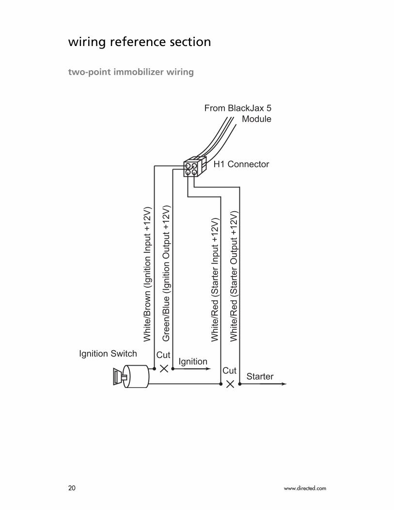
wiring reference section
two-point immobilizer wiring
Ignition Switch
From BlackJax 5Module
H1 Connector
CutIgnition
Cut Starter
Whi
te/B
row
n (Ig
nitio
n In
put +
12V
)
Gre
en/B
lue
(Igni
tion
Out
put +
12V
)
Whi
te/R
ed (S
tarte
r Inp
ut +
12V
)
Whi
te/R
ed (S
tarte
r Out
put +
12V
)
© 2005 directed electronics—all rights reserved 21
h2 connector
�������������� �� ����
�������������������������
���� ���!�"#$�%&�'��(��
������)�����
���*��+,��� ��-��. )/�"#$
����+,��� ���!�"#$�01&�'��(��
�����+ ����"&$
�+,�����.� �� �2�0��.��2 �/ �����"������ ))���#����&$
����3�"��'������&$

www.directed.com22
notes
________________________________________________________________________________________________________________________________________________________________________________________________________________________________________________________________________________________________________________________________________________________________________________________________________________________________________________________________________________________________________________________________________________________________________________________________________________________________________________________________________________________________________________________________________________________________________________________________________________________________________________________________________________________________________________________________________________________________________________________________________________________________________________________________________________________________________________________

© 2005 directed electronics—all rights reserved 23