blackmer compressors installation, operation ... - 3l.p. gas · pdf fileblackmer - 1 -...
TRANSCRIPT

Blackmer - 1 - Compressors
SAFETY DATA
This is a SAFETY ALERT SYMBOL.When you see this symbol on the product, or in themanual, look for one of the following signal wordsand be alert to the potential for personal injury or
property damage.
Warns of hazards that WILL cause serious personalinjury, death or major property damage.
Warns of hazards that CAN cause serious personalinjury, death or major property damage.
Warns of hazards that CAN cause personal injury,or property damage.
NOTICEIndicates special instruction which are very impor-
tant and must be followed.
MODEL: .................................. ID#:................................... SERIAL NO:.........................................
Before proceeding:1. Note the nameplate data in the space provided above.2. Obtain the appropriate parts lists for the model in question.
NOTICEBlackmer compressors MUST only be installed insystems which have been designed by qualifiedengineering personnel. The system MUST conformto all applicable local and national regulations andsafety standards.These instructions are intended to assist in theinstallation and operation of Blackmer compres-sors and MUST be kept with the compressor.Blackmer compressor service and maintenanceshall be performed by qualified technicians ONLY.Service and maintenance shall conform to all ap-plicable local and national regulations and safetystandards.For handling liquefied gas, it is recommended thatNFPA Pamphlet 58 be consulted.
blackmerblackmerblackmerblackmerblackmer compressorsINSTALLATION, OPERATION & MAINTENANCE INSTRUCTIONS
MODELSLB161B LB361B LB601BLB162B LB362C LB602B
blackmerblackmerblackmerblackmerblackmercompressors

Blackmer - 2 - Compressors
GENERAL INFORMATION
TABLE OF CONTENTS
SAFETY DATA............................................................ 1
GENERAL INFORMATIONCompressor Data ........................................................ 3Nameplate Data .......................................................... 4Maximizing Compressor Life ..................................... 5
INSTALLATIONLocation and Piping .................................................... 5Mounting the Compressor Unit .................................. 6Liquefied Gas Transfer Piping Schematic ................ 6Typical Transfer Compressor, Drawing ..................... 7Relief Valves ............................................................... 74-Way Valves .............................................................. 7Liquid Traps ................................................................. 8Temperature and Pressure Switches ......................... 8Pressure Gauges ........................................................ 8
OPERATIONPre-Start up Check List .............................................. 9Start Up Procedure ..................................................... 9
MAINTENANCEService Schedule ...................................................... 10Tool List ..................................................................... 11Bolt Torque Table ...................................................... 11Crankcase Lubrication .............................................. 12Setting the Oil Pressure ........................................... 12
COMPRESSOR DISASSEMBLY............................. 13
COMPRESSOR ASSEMBLY ................................... 14
VALVE REPLACEMENT .......................................... 17
SEAL (PACKING) REPLACEMENT ....................... 19
BEARING REPLACEMENT..................................... 20
OIL PUMP REPLACEMENT.................................... 21
EXTENDED STORAGE............................................ 22
TROUBLESHOOTING ............................................. 23
ISO 9000 CERTIFICATE .......................................... 30

Blackmer - 3 - Compressors
GENERAL INFORMATION
Single-Seal ModelsDouble-Seal Models
LB161BLB162B
LB361BLB362B
LB601BLB602B
Minimum / Maximum RPM* 350 / 825 350 / 825 350 / 790
Displacement@ min rpm-CFM (m/hr)@ max rpm-CFM (m/hr)
7.16 (12.2)16.9 (28.7)
15.3 (26.0)36.0 (61.2)
27.2 (46.3)61.5 (104.5)
Max. BHP (kw) 10 (7.5) 15 (11) 40 (30)
MAWP - psia (kPa) 350 (2,413)
Maximum discharge Temperature 350°F (176°C)
*Reduce maximum speeds by 9% for continuous duty operation.
3
3
Table 1 - Compressor Data
The models listed are single-stage, vertical, air-cooledreciprocating style compressors with single actingcylinders.
Three basic sizes are offered with single or double sealarrangements available.
Figure 1 - Typical Compressor
Blackmer - 4 - Compressors
GENERAL INFORMATION
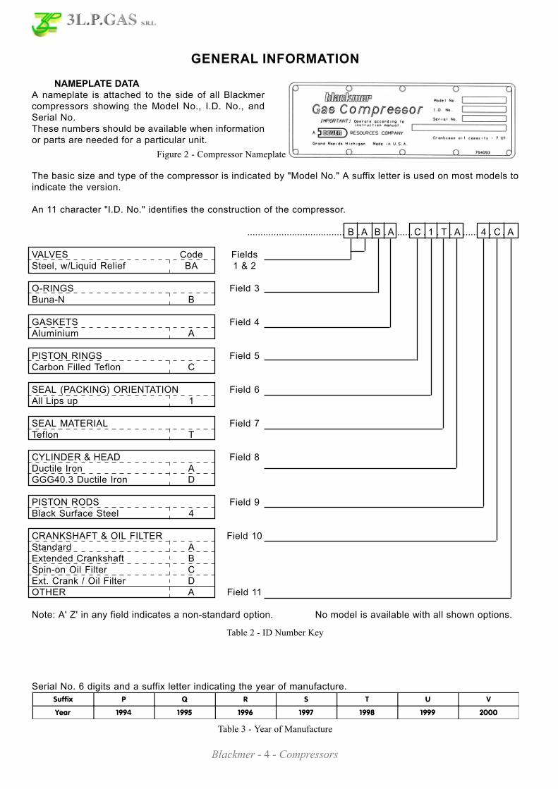
NAMEPLATE DATAA nameplate is attached to the side of all Blackmercompressors showing the Model No., I.D. No., andSerial No.These numbers should be available when informationor parts are needed for a particular unit.
Table 2 - ID Number Key
Table 3 - Year of Manufacture
Suffix P Q R S T U V
Year 1994 1995 1996 1997 1998 1999 2000
Serial No. 6 digits and a suffix letter indicating the year of manufacture.
The basic size and type of the compressor is indicated by "Model No." A suffix letter is used on most models toindicate the version.
An 11 character "I.D. No." identifies the construction of the compressor.
..................................... B .A .B . A ...... C . 1 . T . A ...... 4 . C . A
VALVES Code FieldsSteel, w/Liquid Relief BA 1 & 2
O-RINGS Field 3Buna-N B
GASKETS Field 4Aluminium A
PISTON RINGS Field 5Carbon Filled Teflon C
SEAL (PACKING) ORIENTATION Field 6All Lips up 1
SEAL MATERIAL Field 7Teflon T
CYLINDER & HEAD Field 8Ductile Iron AGGG40.3 Ductile Iron D
PISTON RODS Field 9Black Surface Steel 4
CRANKSHAFT & OIL FILTER Field 10Standard AExtended Crankshaft BSpin-on Oil Filter CExt. Crank / Oil Filter DOTHER A Field 11
Note: A' Z' in any field indicates a non-standard option. No model is available with all shown options.
Figure 2 - Compressor Nameplate

Blackmer - 5 - Compressors
GENERAL INFORMATION
MAXIMIZING COMPRESSOR LIFELife of critical compressor components such as pistonrings, valves and packing will vary considerably witheach appl icat ion, instal lat ion, and operat ingprocedures. Premature failure of wear parts can oftenbe attributed to one of the following causes:
1. Excessive Temperatures Primary causes are:
• Operat ing at pressures other than thoseoriginally specified.
• Handling a different gas than originally specified.• Clogged strainer or filter elements.• Line sizes too small, or other flow restrictions.• Excessive ambient temperature or suction gas
temperature.• Valve problems. (See Foreign Material.)• Badly worn piston rings. (See Foreign Material.)
Lower operating temperatures will increase valve andpiston ring life significantly.
2. Foreign MaterialSolid particles in the gas stream will:
• Rapidly wear the piston rings and score thecylinder wall.
• Destroy the rod packing causing excessiveleakage and score the piston rods.
• Lodge in the valves causing loss of capacity andbroken valve plates and springs.
Liquid in the gas stream will:• Cause broken valve plates and springs.• Destroy the compressor if present in sufficient
quantity.
On new installations, it is suggested that the valvesand piston rings be inspected after the first few hundredhours of operation. This will give an early indication ofany abnormal problems and allow for corrective actionto be taken before a costly failure results. Althoughpiston ring life will vary from application to application,wear be fairly consistent on subsequent sets of rings.
INSTALLATION
LOCATION AND PIPINGCompressor life and performance can be significantlyreduced when installed in an improperly designedsystem. Before starting layout and installation of thepiping system, consider the following:
1. All piping must be leak free to a pressure of 1.5times the maximum system pressure.
NOTICE: If the system is to be hydrostaticallytested, the compressor MUST be isolated.Liquid entering the compressor will causedamage and void the warranty.
2. A strainer should be installed in the inlet line toprotect the compressor from foreign matter.A #30 mesh screen or finer is recommended.Strainer must be cleaned every 180 days, or morefrequently if the system requires.
3. Expansion joints, placed within 36" (0.9 m) of thecompressor, will compensate for expansion andcontraction of the pipes.
4. Piping must be adequately supported to ensure thatno piping loads are placed upon the compressor.
5. Both suction and discharge piping should slopedown from the compressor. The compressor shouldnot be placed at a low point in the piping system.
Blackmer - 6 - Compressors
INSTALLATION
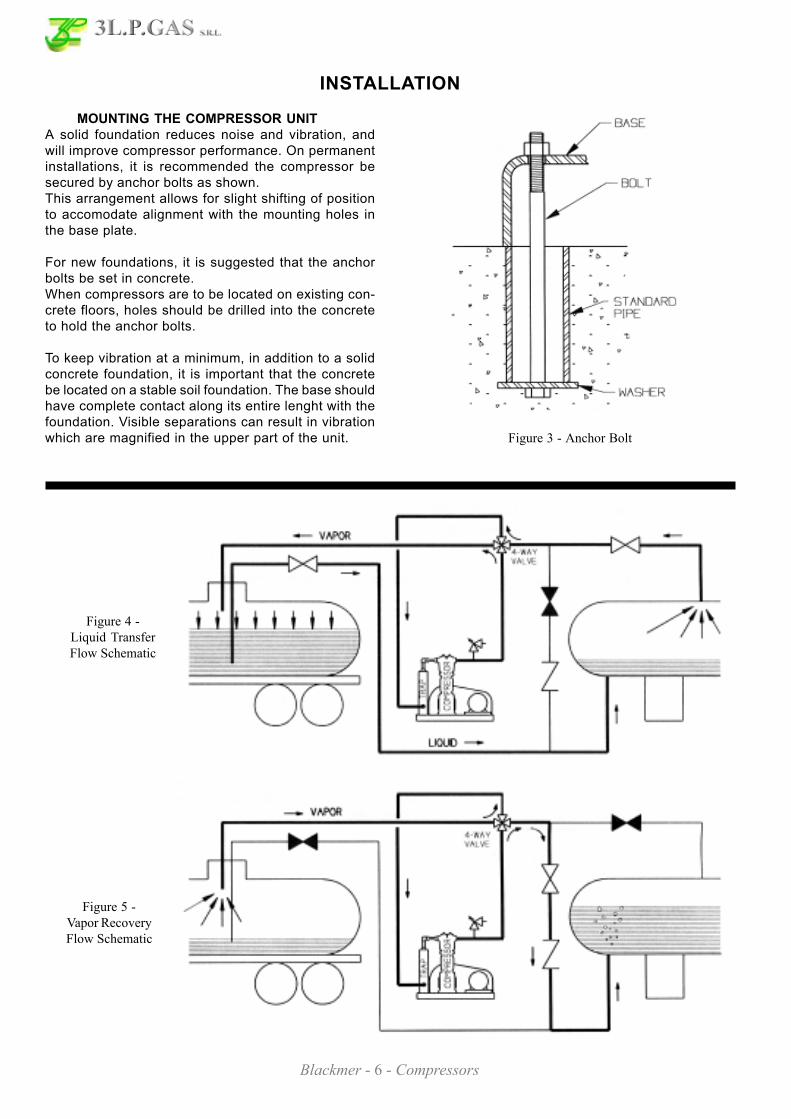
MOUNTING THE COMPRESSOR UNITA solid foundation reduces noise and vibration, andwill improve compressor performance. On permanentinstallations, it is recommended the compressor besecured by anchor bolts as shown.This arrangement allows for slight shifting of positionto accomodate alignment with the mounting holes inthe base plate.
For new foundations, it is suggested that the anchorbolts be set in concrete.When compressors are to be located on existing con-crete floors, holes should be drilled into the concreteto hold the anchor bolts.
To keep vibration at a minimum, in addition to a solidconcrete foundation, it is important that the concretebe located on a stable soil foundation. The base shouldhave complete contact along its entire lenght with thefoundation. Visible separations can result in vibrationwhich are magnified in the upper part of the unit.
Figure 5 -Vapor RecoveryFlow Schematic
Figure 3 - Anchor Bolt
Figure 4 -Liquid TransferFlow Schematic

Blackmer - 7 - Compressors
INSTALLATION
Figure 6 - Typical Liquefied Gas Transfer Compressor
RELIEF VALVESA relief valve of a type, material and pressure ratingsuitable to the installation, MUST be installed.The relief valve shall be installed in the discharge linebetween the compressor head and the first block val-ve.
Blackmer offer var ious rel ief valves for gascompatibility:• Brass for LP-Gas service• Aluminium for anhydrous ammonia• Steel, A.S.M.E. code stamped for both services, andother applications.
4-WAY VALVESMany liquefied gas compressors are used for bothliquid transfer and vapor recovery operations.An optional 4-way valve is used to reverse the directionof flow through the system when changing from liquidtransfer to vapor recovery.Both lubricated and nonlubricated models areavailable. Lubricated models should be lubricatedevery 6 months.
Blackmer - 8 - Compressors
INSTALLATION
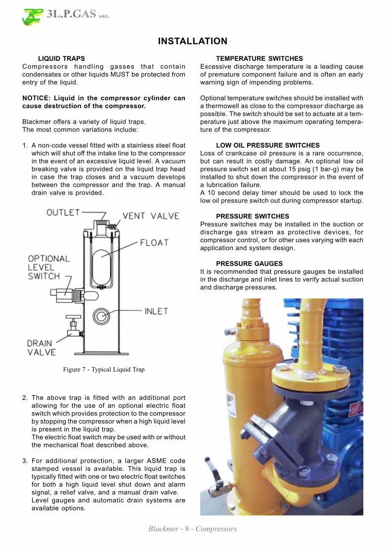
LIQUID TRAPSCompressors handl ing gasses that containcondensates or other liquids MUST be protected fromentry of the liquid.
NOTICE: Liquid in the compressor cylinder cancause destruction of the compressor.
Blackmer offers a variety of liquid traps.The most common variations include:
1. A non-code vessel fitted with a stainless steel floatwhich will shut off the intake line to the compressorin the event of an excessive liquid level. A vacuumbreaking valve is provided on the liquid trap headin case the trap closes and a vacuum developsbetween the compressor and the trap. A manualdrain valve is provided.
2. The above trap is fitted with an additional portallowing for the use of an optional electric floatswitch which provides protection to the compressorby stopping the compressor when a high liquid levelis present in the liquid trap.The electric float switch may be used with or withoutthe mechanical float described above.
3. For additional protection, a larger ASME codestamped vessel is available. This liquid trap istypically fitted with one or two electric float switchesfor both a high liquid level shut down and alarmsignal, a relief valve, and a manual drain valve.Level gauges and automatic drain systems areavailable options.
Figure 7 - Typical Liquid Trap
TEMPERATURE SWITCHESExcessive discharge temperature is a leading causeof premature component failure and is often an earlywarning sign of impending problems.
Optional temperature switches should be installed witha thermowell as close to the compressor discharge aspossible. The switch should be set to actuate at a tem-perature just above the maximum operating tempera-ture of the compressor.
LOW OIL PRESSURE SWITCHESLoss of crankcase oil pressure is a rare occurrence,but can result in costly damage. An optional low oilpressure switch set at about 15 psig (1 bar-g) may beinstalled to shut down the compressor in the event ofa lubrication failure.A 10 second delay timer should be used to lock thelow oil pressure switch out during compressor startup.
PRESSURE SWITCHESPressure switches may be installed in the suction ordischarge gas stream as protective devices, forcompressor control, or for other uses varying with eachapplication and system design.
PRESSURE GAUGESIt is recommended that pressure gauges be installedin the discharge and inlet lines to verify actual suctionand discharge pressures.

Blackmer - 9 - Compressors
OPERATION
PRE-STARTUP CHECK LIST
1. After the compressor is installed in the system, acomplete leak test MUST be performed on both thecompressor and the piping.
2. Re-check the system piping and the piping suppor-ts to ensure that no piping loads are being placedon the compressor.
3. If V-belt driven, check the alignment of the motorand the compressor sheaves. The faces of the she-aves must be parallel.
4. Blackmer compressors are shipped from the factorywithout oil in the crankcase. Fill with a high qualitynon-detergent oil of the proper viscosity.See "Crankcase Lubrication" in this manual.
5. Check the electrical connections for proper wiring,grounding, etc.
6. With the power disconnected, remove the compres-sor nameplate. Squirt oil onto each crosshead whi-le rotating the compressor by hand to verify smo-oth operation.
7. Ensure that all guarding is properly installed.
STARTUP PROCEDURE
1. Start the compressor. Oil pressure should register25 psig(172 kPa) within 10 seconds.
NOTICE: If proper oil pressure is not present,stop the compressor and correct the problem.
Operating the compressor with low oil pressure willcause severe damage to the unit.Adjust if necessary. See "Setting the Oil Pressure"in this manual.
The oil pump on these models will operate in eitherdirection of crankshaft rotation.
2. Verify that the suction and discharge pressures arewithin the expected ranges.
NOTICE: Operating limits listed in the "Com-pressor Data" section must not be exceeded.
3. Check for leakage from the piping and equipment,and repair as necessary.
4. If the seals (packing) have just been replaced, thelower seal MUST be manually lubricated during thefirst 60 minutes of operation.See "Seal (Packing) Replacement" section.New compressors have had the packing broken inat the factory.
5. On newly rebuilt units, the valve hold down screws,valve cover plate bolts and cylinder head boltsMUST have their torque checked after 60 minutesrunning time. Also retighten all hold down bolts,flywheel bolts, etc. after 60 minutes running time.See Table 6 - "Bolt Torque".

Blackmer - 10 - Compressors
MAINTENANCE
Daily Weekly Monthly 6 Months Yearly
Overall Visual Check X
Check Crankcase Oil Pressure X
Check Suction Pressure X
Check Discharge Pressure X
Drain Distance Piece (Double-Seal Models) X
Drain Liquid From Accumulation Points X
Clean Compressor Cooling Fins X
Check Crankcase Oil Level* X*
Check V-Belt Tension X
Change Oil* and Optional External Oil Filter X*
Check Inlet Filter/Strainer Element X
Inspect Valves X
Lubricate 4-way Valve X
Lubricate Motor Bearings per Manufacturer's Suggestions X
Inspect Motor Starter Contact Points X
* Change oil every 1,000 hours of operation (2,000 hours with optional external oil filter),or every 6 months which ever occurs first. If the oil becomes unusually dirty, change oil and external filter
as often as needed to maintain clean oil.
Table 4 - Service Schedule
NOTICE: Blackmer compressor service andmaintenance shal l be performed by qual i f iedtechnicians only. Service and maintenance shallconform to all applicable local and national regulationsand safety standards.
1. Before work is started on the compressor make sureall pressure is bled off on both the suction anddischarge.
2. When performing service or maintenance to thecompressor, refer to the appropriate Blackmer PartsList for detailed views and identification of compressorparts.
SERVICE SCHEDULE

Blackmer - 11 - Compressors
MAINTENANCE
TOOL LIST
BOLT TORQUE FOR BLACKMER COMPRESSOR LBS-FT (Nm)
Description Used For:
Blackmer Wrench 790535 Valve Hold-down screw
Blackmer Packing Installation Tool790536 for 160 and 360 Series Compressors790538 for 600 Series Compressors
Rod-packing protection during installation.
3" Adjustable Spanner with 1/4" pins(Blackmer PN 790316) Piston Nut, Piston, Packing Box Hold-down Ring
9/16", 5/8" or 3/4" End Wrench Cylinder and Crosshead Guide
1 - 1/16" Wrench or Socket Valve Caps
Allen Wrenches: 3/16", 1/4", 3/8" Valves
Sockets: 7/16", 1/2", 9/16", 5/8", 3/4", 7/8" Various
Internal Snap Ring Pliers Seal Replacement
Feeler gauges or Depth Micrometer Piston Clearance
Screwdriver, Flat Blade Nameplate screws, Packing Installation
Pliers
Rubber Mallet
Arbor Press Wrist Pin Removal
Bearing Puller Crankshaft Bearings
Torque Wrench, 0 to 45 lb-ft range Various
Hoist (useful) Cylinder and Crosshead Guide
Table 6 - Bolt Torque
Table 5 - TOOL LIST
Size ConnectinRod Bolt
BearingCarrier
BearingCoverPlate
CrankcaseInspection
Plate
CrossheadGuide Cylinder Head
ValveCoverPlate
ValveHoldDownScrew
160 30(40.7)
30(40.7)
35(47.5)
7(9.5)
25(33.9)
25(33.9)
20(27.1) - - 40
(54.2)
360 35(47.5)
30(40.7)
35(47.5)
7(9.5)
35(47.5)
35(47.5)
40(54.2)
35(47.5)
40(54.2)
600 45(61.0)
30(40.7)
40(54.2)
7(9.5)
40(54.2)
40(54.2)
40(54.2)
35(47.5)
40(54.2)

Blackmer - 12 - Compressors
MAINTENANCE
Figure 8 - Compressor Lubrication System
CRANKCASE LUBRICATIONChange the crankcase oil every 1,000 hours or 180days, whichever is shorter.Under severe dusty or sandy operating conditions, theoil should be changed every 500 hours or every 90days. When equipped with an optional spin-on oil filter,intervals between oil changes may double, but mustnot exceed 180 days.A high quality non-detergent oil is recommended.Consult factory for special lubricating requirements.
Remove the oil pickup screen and clean in a suitablesolvent. When reinstalling the pickup screen, inspectthe metal gasket and the O-ring for damage, replacingas necessary. If equipped, replace the optional externaloil filter. See Figure 8.
SETTING THE OIL PRESSURE (see Figure 8)1. The oil pressure should be about 25 psig (173 KPa).
2. Loosen the locknut.
3. Increase the pressure setting by turning theadjusting screw inward, CLOCKWISE.Decrease the pressure setting by turning theadjusting screw outward, COUNTERCLOCKWISE.
4. Retighten the locknut.
Models Quarts
LB 161 B , LB 162 B 2
LB 361 B , LB 362 C 3
LB 601 B , LB 602 B 7
Table 7 - Oil Capacity
Air Temperature Oil Viscosity
Below 0°F (-18°C) SAE 5 W
0 to 32°F (-18 to 0°C) SAE 10 W
32 to 80°F (0 to 27°C) SAE 20 W
80°F (27°C) and above SAE 30 W
Table 8 - Oil Viscosity
Before changing the oil, bring the compressor up tonormal operating temperature.Remove the crankcase drain plug and drain the oil intoan adequately sized container.

Blackmer - 13 - Compressors
COMPRESSOR DISASSEMBLY
NOTICE: Before starting work on the compressor,make sure all pressure is bled off on both thesuction and discharge.
1. Remove the center head capscrews from thecylinder head. Remove the outer cylinder headcapscrews.
2. Remove the cylinder head assembly and cylinderhead O-rings from the cylinder. The suction anddischarge valve assemblies will come off with thecylinder head. For valve replacement instruction,refer to the "Valve Replacement" section of thismanual.
3. Removal of the piston requires a 32 adjustablespanner wrench with 1/4" pins, such as BlackmerPN 790316.a. Rotate the flywheel by hand to bring a piston to
top dead center of the cylinder.b. Remove the piston nut by turning the nut
counterclockwise. (The nylon locking insert inthe piston nut must be replaced duringreassembly.)
c. To remove the piston from the cylinder, turn itcounterclokwise with the use of the adjustablespanner wrench. For removal and replacementof the piston rings, refer to the "CompressorAssembly" section.
d. Remove the thrust washer and any shims.Keep the shims and piston together.
e. Repeat these steps for the other piston.
4. Remove the cylinder capscrews.
5. Lift the cylinder and cylinder O-rings from thecrosshead guide (or distance piece).
6. Packing Box Removala. Using an adjustable spanner wrench, remove the
packing box hold-down rings.(Replace the nylon locking inserts in the hold-down rings during reassembly.)
b. Remove the packing box and packing box O-ring from each piston rod. Double-Seal modelswill also have a spacer ring and a second packingbox O-ring to remove from each piston rod.
c. For disassembly of the packing boxes, refer tothe "Seal (Packing) Replacement" section of thismanual.
7. Remove the crosshead guide capscrews, and liftthe crosshead guide and gasket from the crankcase.
8. To remove the connecting rod assemblies, with thecrossheads attached, it may be necessary to drainthe oil from the crankcase.The piston rod is permanently attached to thecrosshead to form a single assembly. Do not attemptdisassembly.a. Remove the inspection plate from the crankcase.b. Remove the locknuts from the connecting rod
bolts. This will release the connecting rod cap(the lower half of the connecting rod) and thetwo halves of the bearing insert. The connectingrod and the connecting rod cap are marked witha dot on one side so that they can be properlyaligned when reassembling.
c. Lift the crosshead assembly and connecting rodoff the top of the crankcase.
NOTICE: The connecting rod parts are notinterchangeable and must be reassembledwith the same upper and lower halves.To avoid confusion, work on one connectingrod at a time, or mark the individual halveswith corresponding numbers.
9. Remove the opposite connecting rod andcrosshead assembly in the same manner asoutlined in step 8.

Blackmer - 14 - Compressors
COMPRESSOR DISASSEMBLY
10. Rest the crosshead assembly on a bench.Carefully drive the wrist pin and wrist pin plugsout of the crosshead and connecting rod usinga suitable pin driver or an arbor press.Removal of the pin releases the crossheadassembly from the connecting rod.
12. If necessary, the wrist pin bushing can bereplaced after the crossheads are removed.New bushing must be honed to the proper sizeafter installation.
13. To replace the crankshaft bearings, thecrankcase must be disassebled, and thecrankshaft removed. refer to the "BearingReplacement" section of this manual.
COMPRESSOR ASSEMBLY
COMPRESSOR ASSEMBLYCompressor assembly is generally the opposite ofcompressor disassembly. Before reassembling, cleaneach part throughly. Check all machined surfaces forburrs or roughness, and file lightly if necessary.Replace any O-rings or gaskets that are removedor disturbed during service.
1. CRANKCASE ASSEMBLYAfter replacing the crankshaft, bearing carrier, andbearing cover plate, the connecting rod andcrosshead can be assembled in the crankcase. Seethe "Bearing Replacement" section.
a. To attach the connecting rod to the crossheadassembly, first coat the wrist pin, the wrist pinbore in the crosshead assembly, and the wristpin bushing in the connecting rod with grease.
b. Start the wrist pin in the bore of the crossheadassembly and tap lightly until the pin begins toproject through to the inside of the crossheadassembly.
c. Slide the connecting rod up inside of thecrosshead assembly and align the bushing withthe wrist pin.
d. Lightly tap the wrist pin through the connectingrod until it is centered in the crosshead assembly.The wrist pin should be snug in the crossheadassembly. The connecting rod should rotatefreely on the wrist pin, but should not be loose.
e. Dip the wrist pin plugs in grease and press themagainst the ends of the wrist pin.
f. Place the bearing halves into each half of theconnecting rod, aligning the bearing tangs withthe slots in the connecting rod.Coat the bearing with grease.
g. Set the top of the connecting rod over thecrankshaft journal. Replace the connecting rodcap with the dots on the connecting rod and capon the same side.
h. Start the nuts on the connecting rod bolts andtorque per Table 6 - "Bolt Torque."
i. Follow this same procedure for the oppositeconnecting rod.
2. CROSSHEAD GUIDEa. Place the crosshead guide gasket on top of the
crankcase.b. Lubricate the inside bore of the crosshead gui-
de with light oil.
CompressorModel
Bushing I.D.Inches (mm)
LB 161 B , LB 162 BLB 361 B , LB 362 C
0.8753 to 0.8756(22.233 to 22.240)
LB 601 B , LB 602 B 1.2511 to 1.2514(31.778 to 31.786)
Table 9 - Wrist Pin Bushing Dimensions

Blackmer - 15 - Compressors
COMPRESSOR ASSEMBLYc. Set the crosshead guide over the piston rods and
the crossheads, and slowly lower it against thecrankcase. Make certain that the crossheadassemblies are started straight in the bores ofthe crosshead guide to prevent binding whenlowering the crosshead guide into position.
d. Install the crosshead guide capscrews.DO NOT tighten.
3. Fill the crankcase with oil. Refer to the "CrankcaseLubrication" section. Squirt oil into the crankshaft,roller bearings, crankshaft journals, and crossheadassemblies to ensure proper lubrication at start up.
4. Attach the inspection plate and the inspection plategasket to the crankcase.
5. PACKING BOX ASSEMBLIESBefore install ing the packing boxes into thecrosshead guide, inspect the piston rods for scoringor roughness. Remove any burrs or sharp edges.Lubricate the piston rods and packing box O-ringswith light oil. Do not damage the packing whenstarting it over the rod.
Single-Seal Modelsa. Insert the packing box O-ring into the crosshead
guide.b. Start the packing box assembly, short end down,
over the piston rod and into the counter-boredhole of the crosshead guide.
c. Install the packing box retainer ring, with newnylon locking inserts, and tighten securely.
d. Repeat the above steps for the remainingpacking box.
Double-Seal Modelsa. Insert the lower packing box O-ring into the
crosshead guide.b. Start the packing box assembly, short end down,
over the piston rod and into the crosshead gui-de.
c. After the lower set of packing is started over thepiston rod, make sure the oil deflector ring isproperly aligned (with the flat side down) overthe piston rod. Use the hole in the side of thepacking box to center the deflector ring.Once the deflector ring is over the rod, thepacking box can be fully inserted.
d. Install the upper packing box O-ring on the endof the packing box.
e. Place the packing box spacer ring over the O-ring.
f. Install the packing box retainer ring, with newnylon locking inserts, and tighten securely.
g. Repeat the above steps for the remainingpacking box.
6. Rotate the crankshaft by hand a few times, thenuniformly tighten the crosshead guide capscrewsper Table 6 - "Bolt Torque".
7. Break in new packing per the "Seal (Packing)Replacement" section of this manual.
8. CYLINDER ASSEMBLYa. Install new O-rings in the bottom of the cylinder.
A small amount of grease may be used to holdthe O-rings in place during assembly.
b. Set the cylinder over the piston rods and againstthe crosshead guide.
c. Install the cylinder capscrews. DO NOT tighten.
9. PISTON RINGSa. Place an expander in the top groove of the
piston. Place an expander in the second groovewith the break in the expander 180 degrees fromthe break of the top expander. Place the thirdexpander in the bottom groove with its break inthe same position as the top expander.
b. Place piston rings in all three grooves of thepiston. Align the breaks in the piston ringsdirectly opposite the breaks in the correspondingexpanders.

Blackmer - 16 - Compressors
COMPRESSOR ASSEMBLY
10. PISTONSa. Rotate the flywheel by hand to bring one
piston rod to top dead center of the cylinderassembly.
b. Set the thrust washer and one shim on theshoulder of the piston rod.
c. With light pressure, squeeze the piston ringsinward while threading the piston clockwiseonto the rod. Tighten with the 3" adjustablespanner wrench.
d. Follow this same procedure for the secondpiston.
e. Rotate the crankshaft by hand a number oftimes to verify that the pistons are centeredin the cylinder bores. Adjust the cylinder sothat the pistons DO NOT touch the cylinderwalls.
f. Using an alternating pattern, torque thecylinder capscrews per Table 6 - "BoltTorque."
11. PISTON CLEARANCEa. Rotate the flywheel by hand to bring one
piston to the top.b. Measure the distance from the top of the
piston to the top of the cylinder.
c. If necessary, remove the piston and add orsubtract shims accordingly.
d. Install new nylon locking inserts in the pistonretainer nuts.
e. Thread the piston nut onto the piston rod andtighten securely with the spanner wrench.
f. Follow this same procedure for the secondpiston.
12. CYLINDER HEAD ASSEMBLYIf the valve assemblies have been removed fromthe cyl inder head, refer to the "ValveReplacement" section of this manual.a. Place the cylinder head O-rings in the
grooves located on top of the cylinder.b. Place the cylinder head assembly on top of
the cylinder.c. Hand tighten the outer capscrews and center
capscrews into the cylinder head.Gaskets MUST be used on the centercapscrews of the LB 161 and LB 162 models.
d. Uniformly torque the cylinder head capscrewsper Table 6 - "Bolt Torque."
13. Rotate the compressor by hand to verify that itturns freely. Ensure that the pistons are nothitting the cylinder head assembly.
14. Follow all procedures listed in the "Pre-StartupCheck List" and "Startup Procedure" sections ofthis manual.
15. Start the compressor and bring to normaloperating temperature.Stop the compressor, allow it to cool and retorquethe valve hold down screws per Table 6 - "BoltTorque."
Table 10 - Piston Clearance
LB 161 B .010" to .025"(.254 to .635 mm)
LB 162 B .015" to .030"(.381 to .762 mm)
LB 361 B .020" to .035"(.508 to .889 mm)
LB 362 C .025" to .040"(.635 to 1.016 mm)
LB 601 B .020" to .035"(.508 to .889 mm)
LB 602 B .030" to .045"(.762 to 1.143 mm)

Blackmer - 17 - Compressors
VALVE REPLACEMENT
3. Suction valve - Remove the liquid relief valve body,valve assembly and gasket. DO NOT drop the liquidrelief ball and spring into the head interior.
4. Discharge valve - Remove the discharge valvecage, valve assembly and gasket.
5. Inspect the valve for wear or breakage.
6. Ensure that the old gasket is removed, then installa new valve gasket.
7. To reinstall the suction valves:a. Install the valve assembly in the cylinder head.
Ensure the correct orientation and location ofthe valve.
b. Center the liquid relief body on the valveassembly.
c. Install the hold down screw and tighten per Table6 - "Bolt Torque."
d. Drop the liquid relief ball and the liquid reliefspring into the opening of the liquid relief body.
e. Insert the liquid relief adjusting screw and adjustclockwise unt i l the top of the screw isapproximately 3/8" (9.5 mm) above the top ofthe liquid relief body.Add the locknut and tighten securely.
8. To reinstall the discharge valves:a. Install the valve assembly in the cylinder head.
Verify the correct valve orientation and location.b. Center the valve cage on the valve assembly.c. Install the hold down screw and tighten per Table
6 - "Bolt Torque."
9. Install the valve cap and O-ring. A little oil or greaseon the O-ring will help hold it in place duringinstallation.
10. After replacing the valves, rotate the flywheelby hand to check for interference between thepistons and the valves.
11. After 60 minutes running time, remove the val-ve cap and retorque the hold down screw.Replace the valve cap and O-ring.
Figure 9 - Valve Location
Figure 10 - LB 161 or LB 162 Valves
Suction and discharge valves MUST be installed inthe correct cylinder head locations.See Figure 9.
MODELS LB 161 B or LB 162 B - see Figure 10.1. Remove the valve cap and O-ring from the valve
being serviced.
2. Remove the valve hold down screw with a spannerwrench, such as Blackmer PN 790535.
Blackmer - 18 - Compressors
VALVE REPLACEMENT
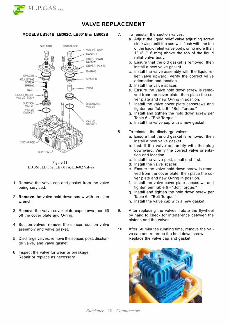
MODELS LB361B, LB362C, LB601B or LB602B 7. To reinstall the suction valves:a. Adjust the liquid relief valve adjusting screw
clockwise until the screw is flush with the topof the liquid relief valve body, or no more than1/16" (1.6 mm) above the top of the liquidrelief valve body.
b. Ensure that the old gasket is removed, theninstall a new valve gasket.
c. Install the valve assembly with the liquid re-lief valve upward. Verify the correct valveorientation and location.
d. Install the valve spacer.e. Ensure the valve hold down screw is remo-
ved from the cover plate, then place the co-ver plate and new O-ring in position.
f. Install the valve cover plate capscrews andtighten per Table 6 - "Bolt Torque."
g. Install and tighten the hold down screw perTable 6 - "Bolt Torque."
h. Install the valve cap with a new gasket.
8. To reinstall the discharge valves:a. Ensure that the old gasket is removed, then
install a new valve gasket.b. Install the valve assembly with the plug
downward. Verify the correct valve orienta-tion and location.
c. Install the valve post, small end first.d. Install the valve spacer.e. Ensure the valve hold down screw is remo-
ved from the cover plate, then place the co-ver plate and new O-ring in position.
f. Install the valve cover plate capscrews andtighten per Table 6 - "Bolt Torque."
g. Install and tighten the hold down screw perTable 6 - "Bolt Torque."
h. Install the valve cap with a new gasket.
9. After replacing the valves, rotate the flywheelby hand to check for interference between thepistons and the valves.
10. After 60 minutes running time, remove the val-ve cap and retorque the hold down screw.Replace the valve cap and gasket.
Figure 11 -LB 361, LB 362, LB 601 & LB602 Valves
1. Remove the valve cap and gasket from the valvebeing serviced.
2. Remove the valve hold down screw with an allenwrench.
3. Remove the valve cover plate capscrews then liftoff the cover plate and O-ring.
4. Suction valves: remove the spacer, suction valveassembly and valve gasket.
5. Discharge valves: remove the spacer, post, dischar-ge valve, and valve gasket.
6. Inspect the valve for wear or breakage.Repair or replace as necessary.

Blackmer - 19 - Compressors
SEAL (PACKING) REPLACEMENT
1. Follow steps 1 through 6 of the "CompressorDisassembly" section of this manual.
2. Remove the upper and lower retainer ring from thepacking box being serviced.Disassemble the packing box and discard the oldpacking sets and packing springs.
3. Clean the packing box in a suitable solvent.Inspect the bore for wear, roughness, or corrosion.Clean or replace as necessary.
4. Ensure that the 6th digit of the Compressor IDnumber is a "1", indicating a TYPE 1 packingarrangement. See "Nameplate Data" in this manual.Refer to Figures 12 and 13 for proper TYPE 1component location and orientation.
5. Single-Seal Packing Boxesa. Install the lower retainer ring.b. Install the packing rings, spring, washers, and
the upper retainer ring. To ease installation onthe second retainer ring, use a screwdriverhandle and press on the last washer to compressthe seal spring slightly.
c. Insert the oil deflector ring through the top ofthe packing box, flat side down, into the cavitybetween the upper and lower packing.The oil deflector ring will be positioned betweenthe two sets of packing.
d. Install the upper packing set starting with theinner retainer ring.
7. The lower packing MUST be manually lubricatedwith oil several times during the first 60 minutes ofcompressor operation.This will prevent overheating of the piston rods andpotential damage to the packing material.
To lubricate the packing:a. Remove the inspection plate from the crosshead
guide.b. Stop the compressor approximately every 5
minutes to allo adequate cooling of the pistonrods.
c. Using a small oil can, lubricate the piston rodseach time the compressor is stopped.
8. Proceed according to steps 5 through 15 of the"Compressor Assembly" section.
Figure 12 - TYPE 1 Seal Orientation
Figure 13 - Typical Seal Assembly

Blackmer - 20 - Compressors
BEARING REPLACEMENT
NOTICE: When replacing the bearings, the entirebearing assembly, including the bearing cup andthe bearing cone, must be replaced.
1. Follow steps 1 through 12 of the "CompressorDisassembly" section.
2. Remove the Oil Pump per the section titled "OilPump Replacement".
3. Remove the flywheel.
4. Remove the bearing carrier and gasket from theoutboard end of the crankcase. The outboardbearing cup will come off with the bearing carrierand will need to be removed with a bearing removaltool.
5. Remove the key from the crankshaft and slide thecrankshaft through the outboard end of thecrankcase. The bearing cones can then be removedwith a bearing puller.
6. Remove the bearing cover plate from the inboardend of the crankcase. The inboard bearing cup ispressed into the crankcase and can be removedwith the use of a bearing removal tool.
c. Note the proper orientation and carefullypress the outboard bearing cup into the bea-ring carrier assembly.
d. Press a bearing cone onto each end of thecrankshaft with the tapered end outward.The bearing race should rest against theshoulder on the crankshaft.
e. Lubricate the bearings with grease.
8. Install the crankshaft through the outboard endof the crankcase.
9. With the oil pump assembly removed, install thebearing carrier and new gasket. The bolt holeposition ensure proper orientation.Tighten the bolts evenly per Table 6 - "Bolt Tor-que."
10. If the bearings have not been replaced, reinstallthe inboard bearing cover plate using the exi-sting shim set. If the bearings have been repla-ced, use a thicker set of shims.
11. Rotate the crankshaft by hand to verify freemovement of the shaft.a. If the crankshaft has an excessive amount of
end play, too many shims have been used.Lateral crankshaft movement (end play)between the bearings should be 0.0015 to0.0030" (0.038 to 0.076 mm).If necessary, remove shims until the end playis within tolerance.
b. If the crankshaft binds, or will not turn, notenough shims have been used pushing thebearing cup too tight against the bearingcone. Remove the crankshaft from thecrankcase and drive the inboard bearing cupout toward the inboard side of the crankca-se.Reinstall the crankshaft and the bearing co-ver plate using additional shims as required.
12. Install the oil pump per the "Oil Pump Replace-ment" section of this manual.
13. Reassemble the compressor according to the"Compressor Assembly" section.
7. To install the bearings:a. Grease the outer edges of the bearing cups.b. Referring to Figure 14 for the proper orientation,
carefully press the inboard bearing cup into thecrankcase until it is flush with the outer surfaceof the crankcase.
Figure 14 - Bearing Locations

Blackmer - 21 - Compressors
OIL PUMP REPLACEMENT
Figure 15 - Oil Pump
1. Remove the oil pump cover bolts and the oil pumpcover.
2. Remove the oil pump assembly, drive cone andspring.
3. Clean and inspect parts for wear or damage, replaceas necessary.
4. Place the spring and the drive cone in the end ofthe crankshaft.
5. Note the slot in the end of the crankshaft and thedrive tab on the back of the oil pump assembly.Install the oil pump assembly into the bearing carrierwith the tab and slot aligned.
6. Note the groove around outer edge of the oil pumpassembly and the stop pin in the oil pump cover.Position the oil pump cover and new gasket withthe pin in the oil pump groove, rotating the oil pumpas needed. The bolt hole positions ensure properorientation of the oil pump cover.
7. BY HAND, tighten the oil pump cover bolts whilethe pump cover is held flush with the bearing carrier.
NOTICE: If by hand tightening, the oil pumpcover cannot be drawn flush with the bearingcarrier, the drive tab or the stop pin areimproperly aligned. DO NOT WRENCH TIGHTENOR THE OIL PUMP WILL BE DAMAGED.
8. Once the oil pump cover is secured by hand, thebolts may be evenly tightened per Table 6 - "BoltTorque."

Blackmer - 22 - Compressors
EXTENDED STORAGE PROCEDURES
If a compressor is not to be put into service for sometime, or if a compressor is to be taken out of servicefor an extended period, the following procedures shouldbe taken.
1. Fill the crankcase with rust inhibiting oil. (Newcompressors are shipped from the factory withoutoil.) Squirt oil on the piston rods and crossheadthrough the nameplate opening.Loosen the V-belts to relieve the load on thebearings. Rotate the compressor by hand a fewtimes to distribute the oil.
2. Plug all openings and purge the compressor withan inert gas such as nitrogen or dry air at about 50psig (3.5 bar-g). This may be done at the factory ifrequested. Leave the compressor pressurized toprevent air or moisture from entering the unit.
NOTICE: Tag the unit with a warning that it ispressurized.
3. If a purge gas is not available, fog oil into thecompressor suction while rotating the unit.Then plug all openings to keep out moisture, insects,etc.
4. Turn the flywheel by hand a few revolutions once amonth to distribute the oil.
5. Store the unit under a plastic wrap on its woodenshipping base up off the ground. If the unit wasboxed for export shipment, leave it in its box.An indoor or covered storage area is preferable.
6. When the compressor is to be put in service, ventthe remaining purge gas and change the crankcaseoil. See the "Pre-Startup Checklist" and "StartupProcedure" sections in this manual.
Compressor is pressurized with inert gas,CAREFULLY bleed off gas BEFORE
attempting any service.
Figure 16 - Pressurized Compressor Tag

Blackmer - 23 - Compressors
TROUBLESHOOTING
PROBLEM STEP PROBABLE CAUSE WHAT TO CHECK IF PROBLEM STILLEXIST GO TO
STEPS ...
LowTransfer
Rate
1 4-Way Valve Leaking (whenequipped)
Lubricate with a stick lubricant compatible withmaterial being transferred.
2
2 Worn or Broken Piston Rings Check condition of rings by restricting dischargeline. If pressure increases slowly, rings areprobably faulty.
3
3 Plugged Strainer Clean screen as necessary. 4
4 Compressor Valve Faulty Remove and inspect for broken or worn springs,discs, or bodies.
5
5 Liquid Relief Valves Need Adjusting Adjust per instructions in "Valve Replacement." 6
6 Compressor Drive Slipping Tighten belts, check for sheared keys, loose keys orloose flywheel.
7
7 Piping Improperly Designed orInstalled
Use proper pipe sizes. 8
No Flow 8 Liquid Trap Full Drain liquid trap through drain valve. Relievevacuum through bleeder valve on top of liquidtrap.
9
9 Excess Flow Valves Slugged Stop the compressor to let the excess flow open.Installation of a valved bypass line between thesuction and discharge lines my be necessary.
6 & 7
Knoks orOtherNoises
10 Loose Valves Tighten valve hold-down screws. 11
11 Worn Internal Parts Inspect through inspection plates and repair asnecessary.
4
No OilPressure
12 Oil Pump Relief Valve Not ProperlySet.
Set oil pump relief valve. 13
13 Oil Pump Not Working Check the Oil Pump drive tab or stop pin fordamage.
14
14 Low Oil Level Check and fill as necessary. 15
15 Dirty Inlet Strainer Clean Inlet Strainer.
Gas Leakingfrom
CrankcaseBreather
16 Faulty / Worn Packing Replace Packing. 17
17 Piston Rod Scored Replace crosshead assemblies and packing. 18
18 Improper Seal Arrangement See "Seal Arrangements." 19
Shake orVibration
19 Improper Mounting Ensure base is supported full lenght. See "Mountingthe Compressor."
20
20 Nonfunctioning Valves Replace or repair valves.

Blackmer - 24 - Compressors
Suggested Spare Parts for LB 361 B Compressors: CB-5C-031
Part # Description Q.ty. / Unit Comm. Q.ty. Spare Q.ty.
793099 Gasket Set - Buna-N, Aluminium T 1 1 1
793259 Suction Valve Sub-Assembly T 2 2
793279 Discharge Valve T 2 2
793008 Piston Ring T 6 6 6
793012 Piston Ring Expander T 6 6 6
793499 Packing Set T 2 2 2
794726 Oil Filter * 1 6
793004 Wrist Pin I 2 2
793003 Wrist Pin Bushing I 2 2 2
793002 Conrod Bearing I 2 2 2
The following parts would normally be required only for major compressor overhaul.
793029 Crosshead Assembly I 2 1
793142 Bearing Cone 2 2
793126 Bearing Cup 2 2
793009 Conrod Assembly 2 1
793157793191
Crankshaft Assembly with Bearing ConesExtended Crankshaft Assembly *
1
793133 Bearing Adjustment Shim Kit 1
794760 Oil Pump Repair Kit 1
793045 Cylinder 1
The Following Spare Parts Kits Are Available
793229 Top end Kit (Includes 'T' Parts)
793230 Intermediate Kit (Includes 'T' and 'I' Parts)
* Optional Equipment on New Compressors
LB 361 B PARTS LIST
SERIAL # _______________________ ID # ________ ________ _______
Gasket Set, Repair Kitsand Special Tools
Gasket Set Buna-N & Aluminium 793099
Top End Repair Kit 793229Includes Piston Rings & Expanders, Packing Sets,Valves, Gaskets & O-rings
Intermediate Repair Kit 793230Includes Top End Kit plus Wrist Pins & Bushings,Connecting Rod Bearings, and Crossheads.
Packing Installation Tool 790536
Spanner wrench, 1/4" Adjustable 790316
Tool Kit 790199
Bulletins Needed ForComplete Parts List
This page ................ 5E-031
Crankcase .............. 5F-021
Oil Pump................. 5G-011
Flywheel ................. 5H-010
Crosshead ............... 5J-030
Head ....................... 5M-020
CB-5E-031

Blackmer - 25 - Compressors
CB-5F-021
Crankcase Assembly: Models LB 361 B, LB 362 C
Ref. Description Q.ty Part No
1 Crankcase Assembly - StdCrankcase Assembly - w\Oil FilterCrankcase Assembly - w\Ext ShaftCrankcase Assembly - w\Ext Shaft & Oil Filter
1 793103793100793155793171
1A Crankcase 1 793102
2 Oil Intake Screen 1 792135
2B Oil Filter 1 794726
2C Breather Filter 1 792070
3 Oil Screen Plug 1 792145
5A Oil Pump Kit 1 794760
7 Oil Pressure Gauge 1 790012
11 Oil Bayonet Assembly 1 792162
12A Inspection Plate 1 793105
13A Bearing Carrier 1 793104
15A Bearing Cup 2 793126
16 Crankshaft Assembly (w \ 18A, 19, 96B)Crankshaft Assembly-Ext (w \ 18A, 19, 96B)
1 793157793191
18A Bearing Cone 2 793142
19 Orifice 2 792146
Ref. Description Q.ty Part No
20 Bearing Cover Plate 1 793106
21 Oil Seal 1 793143
22A Bearing Adjustment Shim Kit 1 793133
30 Oil Filter Fitting 1 794725
60A Gasket - Oil Screen * 1 792136
60B Gasket - Oil Screen Plug * 1 792123
60C Gasket - Inspection Plate * 1 793122
60D Gasket - Bearing Carrier Assembly * 1 793124
60L Gasket - Oil Pump Cover * 1 794721
61A O-ring - Oil Screen * 1 792175
61D O-ring - Oil Bayonet * 1 792174
63C Capscrew - Hex Hd 6 793116
63D Capscrew - Soc Hd 4 790559
63E Capscrew - Hex Hd 4 792093
63U Capscrew - Hex Hd 6 792093
73A Pipe Plug 1 792166
96A Pipe Plug 1 790488
96B Pipe Plug 2 790309
* Included in Gasket Sets.

Blackmer - 26 - Compressors
CB-5G-011
Oil Pump Detail:Models LB 161 B, LB 162 B, LB 361 B, LB 362 C, LB 601 B, LB 602 B, LB 942 A
Ref. Description Q.ty Part No
2B Oil Filter 1 794726
5A Oil Pump Kit (w/6, 9F, 60L) 794760
6 Oil Pump Cone 1 794750
7 Oil Pressure Gauge 1 790012
8A Oil Pressure Adjusting Ball 1 792154
9A Oil Pressure Adjusting Spring 1 792153
9F Oil Pump Spring 1 794751
10 Oil Pressure Adjusting Screw 1 792148
10A Locknut 1 792152
Ref. Description Q.ty Part No
14 Oil Pump Cover Assembly (w/17A, 96B)Oil Pump Cover AssemblyFor Filter (w/17A, 96B)
1 794763794764
17A Roll Pin 1 794753
30 Oil Filter Fitting 1 794725
60L Gasket - Oil Pump Cover * 1 794721
61C O-Ring - Adjusting Screw * 1 792168
63D Capscrew - Soc. Hd 4 790559
96B Pipe Plug 2 790309
* Included in Gasket Sets.

Blackmer - 27 - Compressors
CB-5H-010
Flywheel Assembly:Models LB 161 B, LB 162 B Models LB 361 B, LB 362 C
Ref. Description Q.ty Part No
23 Key 1 792167
55A Hub 1 790563
57 Flywheel Assembly 1 792073
57A Flywheel 1 792071
Ref. Description Q.ty Part No
23 Key 1 793167
55A Hub 1 790143
57 Flywheel Assembly 1 793047
57A Flywheel 1 792071

Blackmer - 28 - Compressors
CB-5J-030
Crosshead Assembly:Models LB 361 A, LB 361 B
Ref. Description Q.ty Part No
9B Packing Spring 2 792077
12B Inspection Plate 1 793093
25 Connecting Rod Assembly 2 793009
26 Connecting Rod Bearing 2 793002
28 Wrist Pin Bushing * * 2 793003
29 Crosshead Assembly 2 793029
31 Wrist Pin 2 793004
32 Wrist Pin Plug 4 792178
34 Crosshead Guide 1 793091
35A Retainer Ring 4 792088
35B Packing Box 2 793221
35C Packing Set 2 793499
Ref. Description Q.ty Part No
35D Hold-down Ring 2 793220
60E Gasket - Inspection Plate * 1 793092
60F Gasket - Crankcase * 1 793121
61G O-ring (Buna-N) Std * 2 792125
62B Machine Screw - Inspection Plate 8 793096
63F Capscrew - Hex Hd 6 793094
64A Connecting Rod Bolt 4 793006
67A Washer - Packing Box 4 792083
67B Washer - Packing Spring 2 792087
68A Connecting Rod Bolt Nut 4 793007
73C Lock Plug * 6 792030
* Included in Gasket Sets* * Must be honed after installing

Blackmer - 29 - Compressors
Crosshead Assembly:Models LB 361 A, LB 361 B, LB 362 B, LB 362 C
Ref. Description Q.ty Part No
22B Piston Shim - 0.015Piston Shim - 0.007
ARAR
792034792050
36 Cylinder 1 793045
39 Piston 2 793021
40 Expander 6 793012
41 Piston Ring 6 793008
61J O-Ring * 2 793177
61K O-Ring * 2 793641
63R Capscrew - Hex Hd 8 794097
63X Capscrew - Hex Hd 6 794096
67C Thrust Washer 2 792033
69A Piston Nut 2 793022
73C Lock Plug * 4 793028
73D Pipe Plug * 1 793498
* Included in Gasket Sets
CB-5L-030


DESIGN, SALE & INSTALLATION OF L.P.G. - NATURAL GAS SYSTEMS
Via Bologna 14 - 43036 FIDENZA (PR) - ITALYPhone 0524 527766
Fax 0524 525456http://www.3lpgas.com
e-mail:[email protected]