blacknose a3 laser cutter and engraver user...
TRANSCRIPT
Blacknose A3 Laser Cutter and Engraver
User Guide
Version 0.2, July 14th 2015

Precautions The Blacknose A4 Laser Cutter & Engraver
Introduction Specifications Machine Overview
Front Left Side Right Side Rear Top Cutting Bay
Setup and Installation Parts List Work Stand Assembly
Components: Tools Required:
Removing Shipping Materials Air Assist System
Components: Tools Required:
Water Cooling System Components: Tools Required: Filling The Laser Tube Note
Extraction System Components: Tools Required: Notes about extractor vents
Alignment Choosing A Cutting Bed
LaserCut 5.3 Software Introduction System Requirements Communicating to the Laser Cutter The Soft Dog USB Dongle Downloading LaserCut 5.3 Installing Lasercut 5.3 on Windows XP, Vista and Windows 7
Checking the Drivers Installation on Windows 8
Install the Soft Dog USB dongle Running in Compatibility Mode Creating An App On The Start Screen Right-click on the LaserCut 5.3 icon on the Desktop and select Pin to Start from the context menu.
Setting the Model of Laser Cutter Note for Windows 8 users
Running Lasercut 5.3 Working With The Demonstration Version
Creation of cutting files for the laser Creation of native LaserCut files
Basic Drawing Simple Shapes
Line Rectangle Polyline Ellipse Text
Simple Object Modification Rotate Mirror (Vertically) Mirror (Horizontally) Edit Node Size
Advanced Object Modification Copy Centre to Table Invert Colors Offset Curve
Using the Laser Cutter - Workflow Maintenance
Maintenance schedule Mirror/Lens Inspection and Cleaning
Tools & Materials: Time Needed: 10-30 minutes Mirrors Lens
Laser Alignment Tools Required: Overview Preparation Making Masking Tape Targets Part 1: Rough Laser Tube Position Part 2: Mirror 1 Adjustment Part 3: Mirror 2 Adjustment Part 4: Centering The Beam Vertically Part 5: Mirror 3 Adjustment
Troubleshooting


Precautions WARNING!
● Never open access panels without disconnecting power ● Do not circumvent the safety cut-out switch or operate the machine
with access doors open ● Never run the laser cutter unattended ● Always vent material smoke or vapour to a suitable external outlet or
filter system ● Only use laser-safe materials which do not contain chlorides and
formaldehydes
The Blacknose A4 Laser Cutter & Engraver
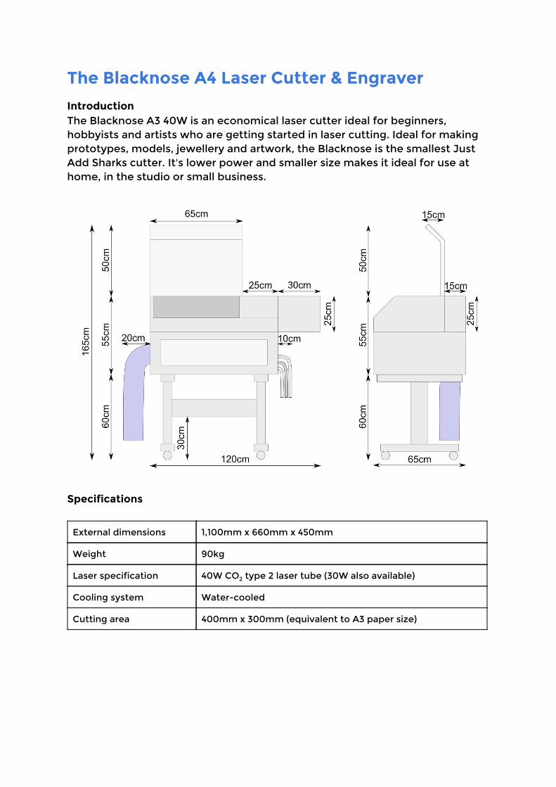
Introduction The Blacknose A3 40W is an economical laser cutter ideal for beginners, hobbyists and artists who are getting started in laser cutting. Ideal for making prototypes, models, jewellery and artwork, the Blacknose is the smallest Just Add Sharks cutter. It's lower power and smaller size makes it ideal for use at home, in the studio or small business.
Specifications
External dimensions 1,100mm x 660mm x 450mm
Weight 90kg
Laser specification 40W CO2 type 2 laser tube (30W also available)
Cooling system Water-cooled
Cutting area 400mm x 300mm (equivalent to A3 paper size)
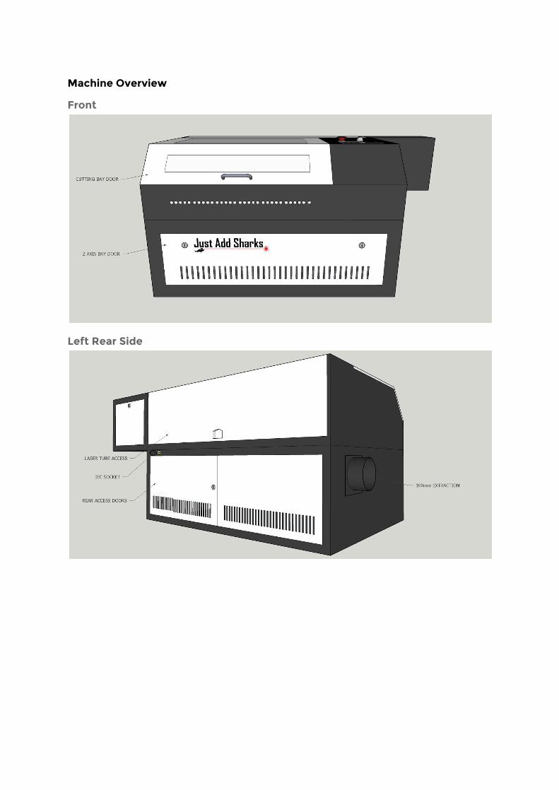
Machine Overview
Front
Left Rear Side

Right Side
Detail

Top
Cutting Bay

Setup and Installation
Parts List • Blacknose A3 Laser Cutter • Knife bed (inside cutter) • Honeycomb bed (inside cutter) • 40 Watt laser tube (installed in cutter) • 4-way, 2 meter switched mains power strip • Air assist parts:
‣ Air pump ‣ Bungee cord ‣ 1 x silicone tube ‣ Brass connector
• Water pump: ‣ Base plate ‣ Pump ‣ Brass connector ‣ 2 x silicone tubes
• Extractor parts: ‣ Extractor fan ‣ 2 x 100mm ⌀ blue extraction hose ‣ 100mm ⌀ extraction vent adapter ‣ 3 x hose clamps (in plastic tool box) ‣ 4 x M5 hex bolts
• Workstand parts: ‣ Cross bar ‣ Left end ‣ Right end ‣ 8 x 12mm M6 hex bolts & washers
• White plastic toolbox: ‣ 3 x hose clamps (for extraction system) ‣ 100mm nozzle end plate ‣ 3 pairs of case keys ‣ Crank-type z-axis operating handle ‣ Alternative Just Add Sharks z-axis operating handle ‣ Leetro ‘Soft Dog’ (dongle for LaserCut software) ‣ Focusing tool ‣ Lockout keys to allow operation of the cutter ‣ Four hex keys: 2.5mm, 3mm, 4mm and 5mm ‣ Small Phillips head screwdriver ‣ Mirror release tool ‣ Digital thermometer 1
‣ Power cable (IEC) ‣ Lens cleaning cloth
1 Only provided with systems which use a water bath cooler
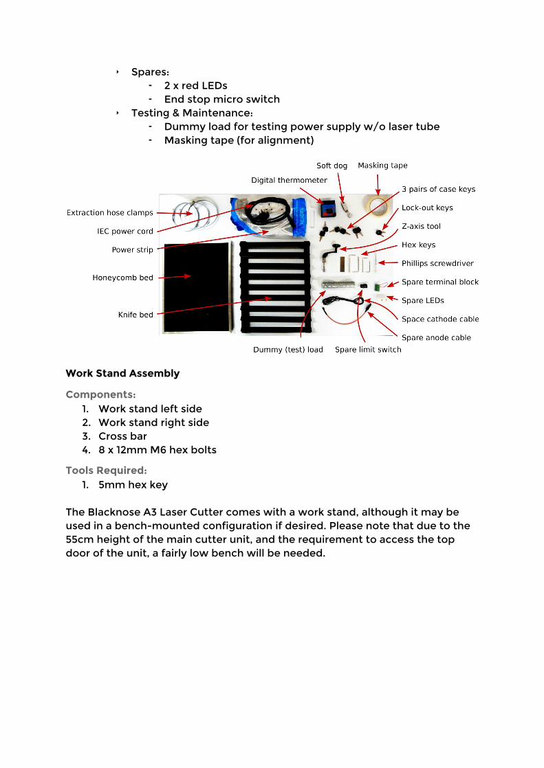
‣ Spares: ⁃ 2 x red LEDs ⁃ End stop micro switch
‣ Testing & Maintenance: ⁃ Dummy load for testing power supply w/o laser tube ⁃ Masking tape (for alignment)
Work Stand Assembly
Components: 1. Work stand left side 2. Work stand right side 3. Cross bar 4. 8 x 12mm M6 hex bolts
Tools Required: 1. 5mm hex key
The Blacknose A3 Laser Cutter comes with a work stand, although it may be used in a bench-mounted configuration if desired. Please note that due to the 55cm height of the main cutter unit, and the requirement to access the top door of the unit, a fairly low bench will be needed.
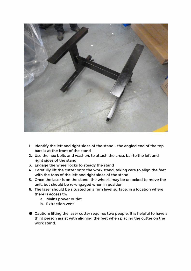
1. Identify the left and right sides of the stand - the angled end of the top bars is at the front of the stand
2. Use the hex bolts and washers to attach the cross bar to the left and right sides of the stand
3. Engage the wheel locks to steady the stand 4. Carefully lift the cutter onto the work stand, taking care to align the feet
with the tops of the left and right sides of the stand 5. Once the laser is on the stand, the wheels may be unlocked to move the
unit, but should be re-engaged when in position 6. The laser should be situated on a firm level surface, in a location where
there is access to: a. Mains power outlet b. Extraction vent
● Caution: lifting the laser cutter requires two people. It is helpful to have a
third person assist with aligning the feet when placing the cutter on the work stand.

Removing Shipping Materials The laser cutter may have foam inserts inside the unit which help protect the machine in transit. Check each openable compartment of the machine and remove any packaging/padding material found.
Air Assist System
Components: 1. Air pump 2. Brass adapter 3. Bungee cord 4. Silicone hose
Tools Required: [none]
1. Attach the brass hose adapter to the air pump 2. Attach one of the silicone hose to the brass adapter (push-fit) 3. Attach the other end of the silicone hose to the connector labeled Air In
on the lower right side of the cutter (push fit)
4. Insert the mains plug from the air pump into one of the sockets on the power strip
Note that the air pump becomes warm when running and so should be placed in a well-ventilated area. The air pump also vibrates when operating. To reduce noise we recommend suspending the air pump with a bungee cord (provided), or resting the pump on a pad of foam or other vibration-absorbing material.
Water Cooling System
Components: 1. Water pump 2. Brass adapter 3. 35 litre plastic box with lid (water reservoir) 4. 2 x silicone hose 5. Digital thermometer
Tools Required: [none]
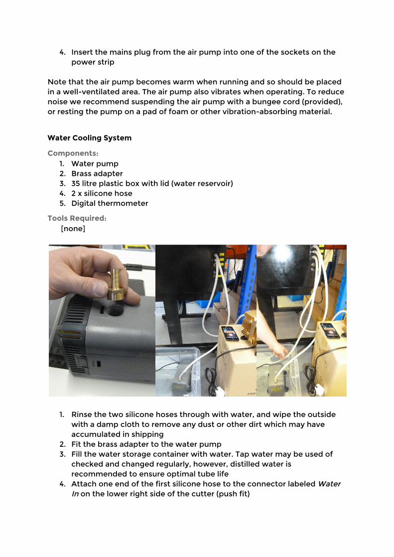
1. Rinse the two silicone hoses through with water, and wipe the outside with a damp cloth to remove any dust or other dirt which may have accumulated in shipping
2. Fit the brass adapter to the water pump 3. Fill the water storage container with water. Tap water may be used of
checked and changed regularly, however, distilled water is recommended to ensure optimal tube life
4. Attach one end of the first silicone hose to the connector labeled Water In on the lower right side of the cutter (push fit)
5. Attach the other end of the first silicone hose to the hose nozzle on the water pump
6. Submerge the pump in the water reservoir 7. Attach one end of the second silicone hose to the connector labeled
Water Out on the lower right side of the cutter (push fit) 8. Place the other end of the second silicone hose in the water reservoir.
The end of the hose should not be placed next to the water intake of the pump
9. Place the digital thermometer probe into the water 10. In an empty slot on the power strip, set the switch to the off position
and insert the mains plug from the air pump into the slot
● Caution: ensure your hands are dry before handling mains cabling or handling the laser cutter
Filling The Laser Tube The first time water is run through the laser tube, it is important to ensure there are no bubbles in the tube : 2
1. Double check both Water In and Water Out sockets on laser have hoses
connected according to the instructions above, and that the water pump is plugged into the power strip. The laser itself should not be connected to the mains
2. Open the laser tube access panel on the rear of the laser cutter 3. Turn on the water pump using the switch on the power strip - the tube
should fill with water 4. Visually examine the tube for bubbles (it may be necessary to slide the
silicone sock along the tube to examine the anode / water inlet area)
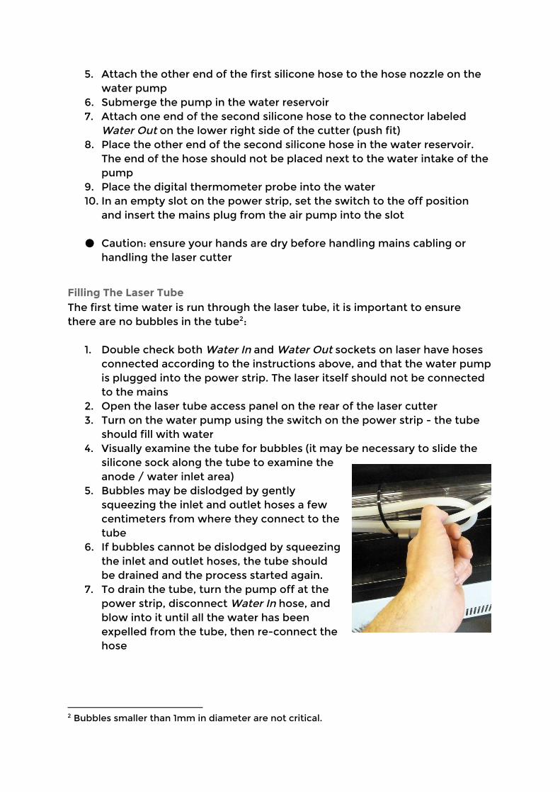
5. Bubbles may be dislodged by gently squeezing the inlet and outlet hoses a few centimeters from where they connect to the tube
6. If bubbles cannot be dislodged by squeezing the inlet and outlet hoses, the tube should be drained and the process started again.
7. To drain the tube, turn the pump off at the power strip, disconnect Water In hose, and blow into it until all the water has been expelled from the tube, then re-connect the hose
2 Bubbles smaller than 1mm in diameter are not critical.
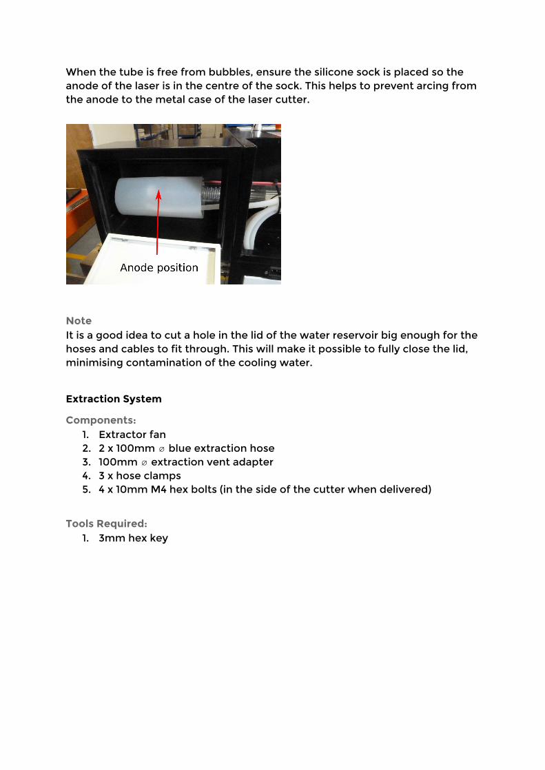
When the tube is free from bubbles, ensure the silicone sock is placed so the anode of the laser is in the centre of the sock. This helps to prevent arcing from the anode to the metal case of the laser cutter.
Note It is a good idea to cut a hole in the lid of the water reservoir big enough for the hoses and cables to fit through. This will make it possible to fully close the lid, minimising contamination of the cooling water.
Extraction System
Components: 1. Extractor fan 2. 2 x 100mm ⌀ blue extraction hose 3. 100mm ⌀ extraction vent adapter 4. 3 x hose clamps 5. 4 x 10mm M4 hex bolts (in the side of the cutter when delivered)
Tools Required: 1. 3mm hex key

1. Attach the 100mm ⌀ extraction vent adapter to the extraction port on the left side of the machine with the hex bolts
2. Fit one end of the first piece of 100mm ⌀ blue extraction hose to the vent adapter, securing it with a hose clamp
3. Fit the other end of the first piece of extraction hose to the intake port of the extractor fan, securing it with a hose clip
4. Fit one end of the second piece of extraction hose to the outlet port of the extractor fan, securing it with a hose clip
5. Insert the other end of the second piece of extraction hose into the extractor vent
Notes about extractor vents Some factors which may be considered when choosing the location of an extractor vent:
• Is the vent near a window / ventilation inlet? (fumes may blow back) • The vent should probably be above head height, but not too close to the
eaves • The vent should not expel fumes into another work area / adjacent
building
Alignment Before the laser is used for the first time, the alignment should be checked. See Laser Alignment for details.

Choosing A Cutting Bed The Blacknose A3 comes with two cutting beds:
1. Honeycomb bed 2. Knife bed
The honeycomb bed allows the use of magnets to hold work securely and flat against the bed, and makes it easier to align the work in the cutter. However, this bed may result is more staining/residue on the work. The knife bed helps reduce staining, but it is not possible to use magnets to hold the work in place. It is suggested that both beds be used - the honeycomb bed placed on top of the knife bed to aid air circulation.
LaserCut 5.3 Software
Introduction
LaserCut 5.3 is a dedicated piece of laser cutter control software written by Leetro Automation Co Ltd. It is used to prepare cutting files that are sent to the Leetro MPC6515 controller on board the laser cutter. LaserCut has some basic drawing functions but it becomes most useful when dxf files are created by other drawing packages, such as the free, cross platform, open source vector editing package Inkscape, and then imported into LaserCut. Lasercut provides functions to simulate the cutting process that is about to occur and estimate how long the cut will take. All the information about a job can be saved and loaded from file making it easy to store and repeat jobs in the future.
System Requirements
● A computer running Windows 2000/XP/7 or 8 ● 2 free USB ports ● Known to run happily on systems with 2 Gb of RAM ● 50 Mb disk space (installation) ● Disk space needed while in use will vary depending on complexity of
work
Communicating to the Laser Cutter
A job may be uploaded from the computer using LaserCut. Once uploaded no further communication with the computer is required to perform the job and it may be shut down or disconnected if required. Jobs can also be transferred to the machine via a USB stick using the USB port on the right side of the cutter.
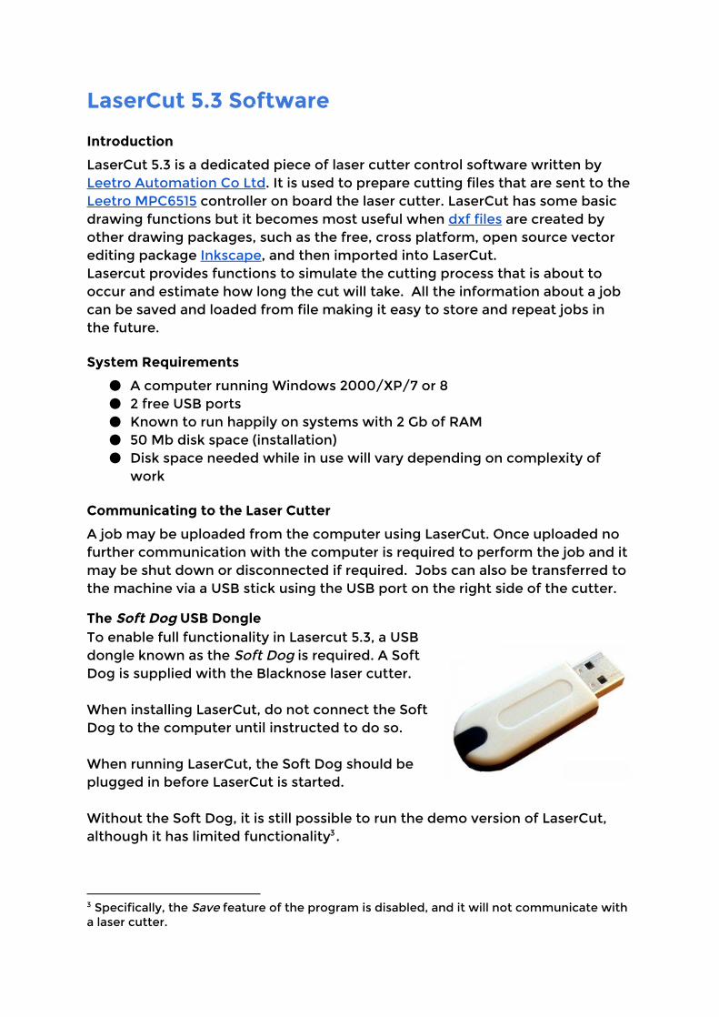
The Soft Dog USB Dongle To enable full functionality in Lasercut 5.3, a USB dongle known as the Soft Dog is required. A Soft Dog is supplied with the Blacknose laser cutter. When installing LaserCut, do not connect the Soft Dog to the computer until instructed to do so. When running LaserCut, the Soft Dog should be plugged in before LaserCut is started. Without the Soft Dog, it is still possible to run the demo version of LaserCut, although it has limited functionality . 3
3 Specifically, the Save feature of the program is disabled, and it will not communicate with a laser cutter.
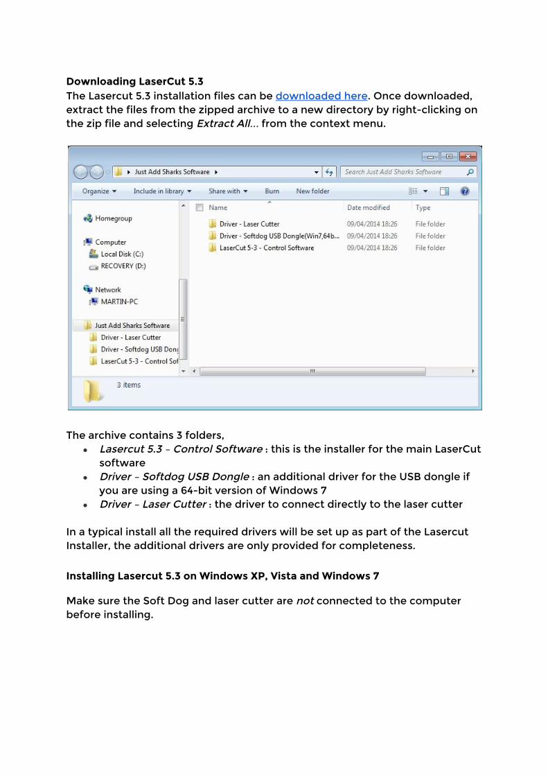
Downloading LaserCut 5.3 The Lasercut 5.3 installation files can be downloaded here. Once downloaded, extract the files from the zipped archive to a new directory by right-clicking on the zip file and selecting Extract All… from the context menu.
The archive contains 3 folders, ● Lasercut 5.3 – Control Software : this is the installer for the main LaserCut
software ● Driver – Softdog USB Dongle : an additional driver for the USB dongle if
you are using a 64-bit version of Windows 7 ● Driver – Laser Cutter : the driver to connect directly to the laser cutter
In a typical install all the required drivers will be set up as part of the Lasercut Installer, the additional drivers are only provided for completeness.
Installing Lasercut 5.3 on Windows XP, Vista and Windows 7
Make sure the Soft Dog and laser cutter are not connected to the computer before installing.
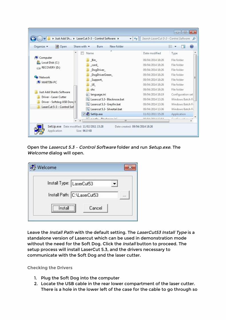
Open the Lasercut 5.3 – Control Software folder and run Setup.exe. The Welcome dialog will open.
Leave the Install Path with the default setting. The LaserCut53 Install Type is a standalone version of Lasercut which can be used in demonstration mode without the need for the Soft Dog. Click the Install button to proceed. The setup process will install LaserCut 5.3, and the drivers necessary to communicate with the Soft Dog and the laser cutter.
Checking the Drivers 1. Plug the Soft Dog into the computer 2. Locate the USB cable in the rear lower compartment of the laser cutter.
There is a hole in the lower left of the case for the cable to go through so
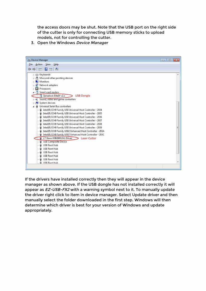
the access doors may be shut. Note that the USB port on the right side of the cutter is only for connecting USB memory sticks to upload models, not for controlling the cutter.
3. Open the Windows Device Manager
If the drivers have installed correctly then they will appear in the device manager as shown above. If the USB dongle has not installed correctly it will appear as EZ-USB-FX2 with a warning symbol next to it. To manually update the driver right click to item in device manager. Select Update driver and then manually select the folder downloaded in the first step. Windows will then determine which driver is best for your version of Windows and update appropriately.

Installation on Windows 8 Make sure the Soft Dog and laser cutter are not connected to the computer before installing.
Switch to the Windows 8 desktop by clicking the desktop icon or typing
desktop into the search box. If you haven’t downloaded and extracted the
zipped software yet, do so by following the instructions in Downloading
LaserCut 5.3.
Open the LaserCut 5-3 – Control Software folder and double click the Setup
program.
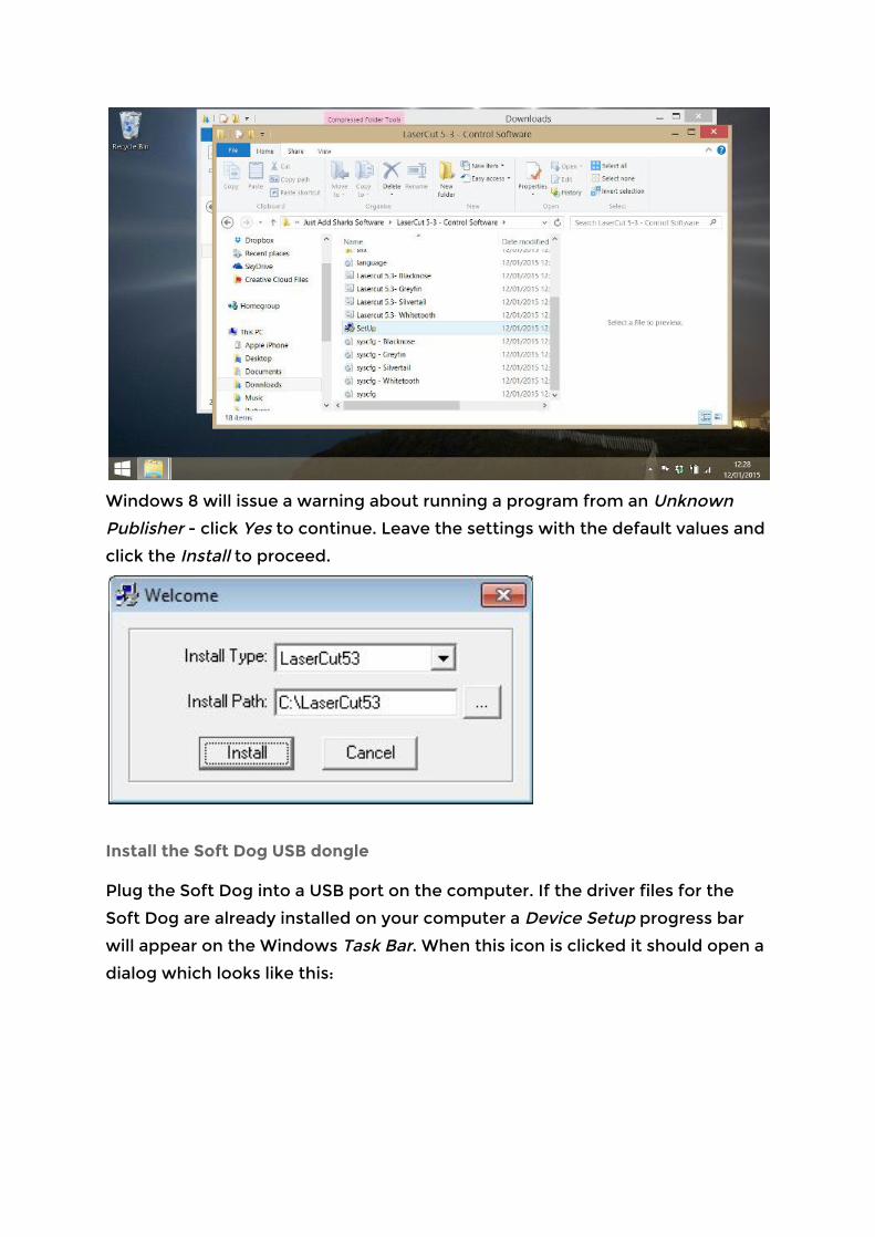
Windows 8 will issue a warning about running a program from an Unknown
Publisher - click Yes to continue. Leave the settings with the default values and
click the Install to proceed.
Install the Soft Dog USB dongle
Plug the Soft Dog into a USB port on the computer. If the driver files for the
Soft Dog are already installed on your computer a Device Setup progress bar
will appear on the Windows Task Bar. When this icon is clicked it should open a
dialog which looks like this:
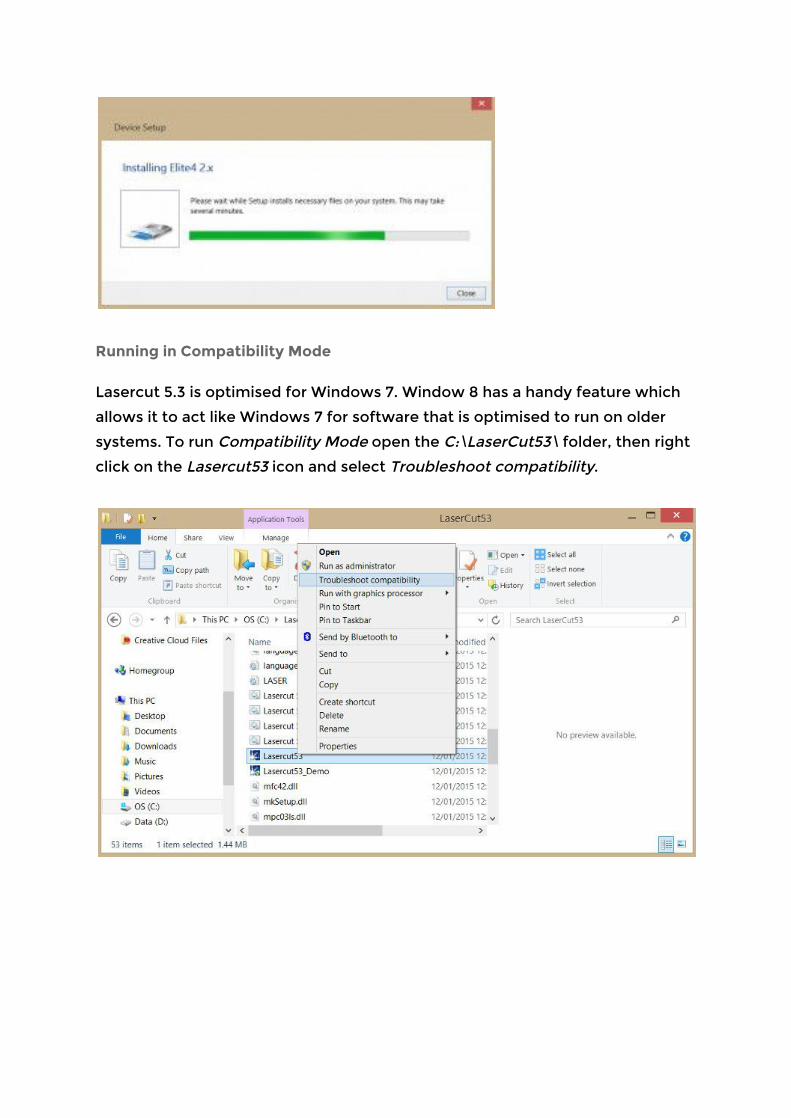
Running in Compatibility Mode
Lasercut 5.3 is optimised for Windows 7. Window 8 has a handy feature which
allows it to act like Windows 7 for software that is optimised to run on older
systems. To run Compatibility Mode open the C:\LaserCut53\ folder, then right
click on the Lasercut53 icon and select Troubleshoot compatibility.

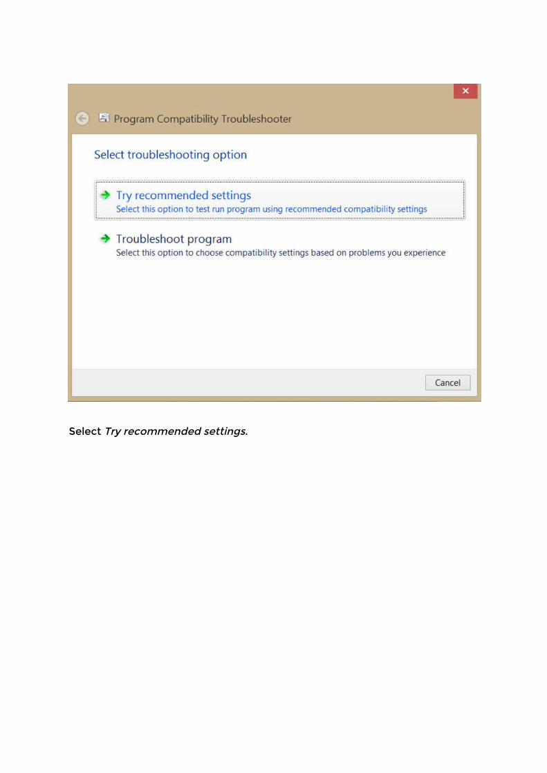
Select Try recommended settings.
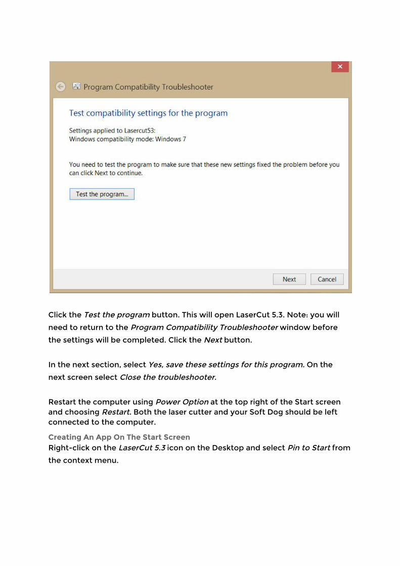
Click the Test the program button. This will open LaserCut 5.3. Note: you will
need to return to the Program Compatibility Troubleshooter window before
the settings will be completed. Click the Next button.
In the next section, select Yes, save these settings for this program. On the
next screen select Close the troubleshooter.
Restart the computer using Power Option at the top right of the Start screen and choosing Restart. Both the laser cutter and your Soft Dog should be left connected to the computer.
Creating An App On The Start Screen Right-click on the LaserCut 5.3 icon on the Desktop and select Pin to Start from
the context menu.
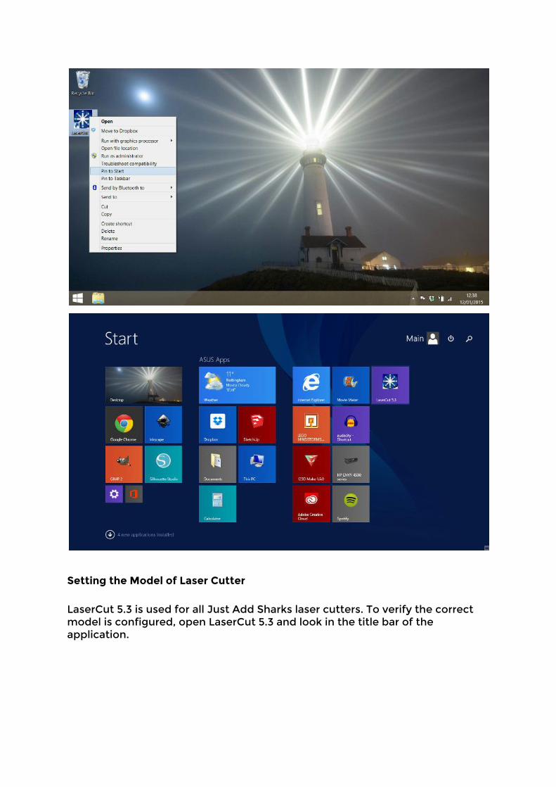
Setting the Model of Laser Cutter
LaserCut 5.3 is used for all Just Add Sharks laser cutters. To verify the correct model is configured, open LaserCut 5.3 and look in the title bar of the application.
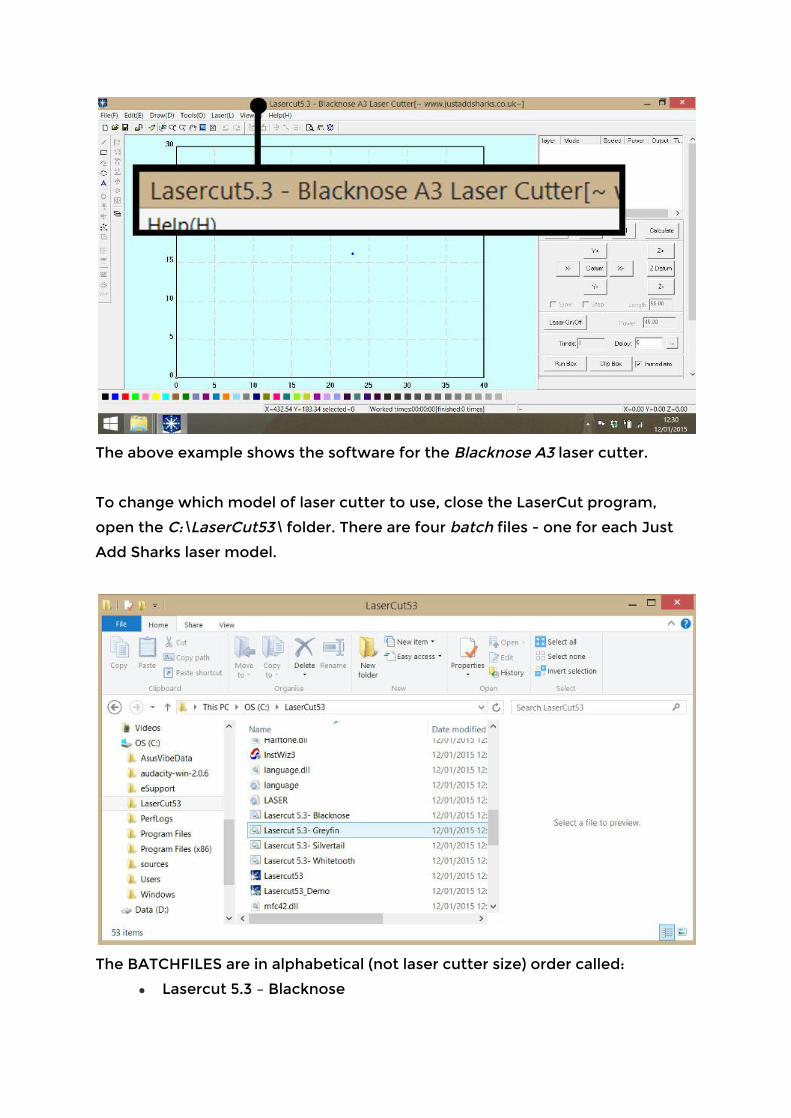
The above example shows the software for the Blacknose A3 laser cutter.
To change which model of laser cutter to use, close the LaserCut program,
open the C:\LaserCut53\ folder. There are four batch files - one for each Just
Add Sharks laser model.
The BATCHFILES are in alphabetical (not laser cutter size) order called:
● Lasercut 5.3 – Blacknose
● Lasercut 5.3 – Greyfin
● Lasercut 5.3 – Silvertail
● Lasercut 5.3 – Whitetooth
To configure LaserCut 5.3 to work with your model of cutter, double-click the
appropriate file.
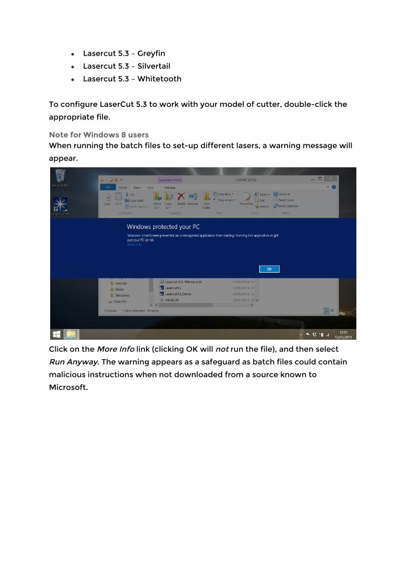
Note for Windows 8 users When running the batch files to set-up different lasers, a warning message will
appear.
Click on the More Info link (clicking OK will not run the file), and then select
Run Anyway. The warning appears as a safeguard as batch files could contain
malicious instructions when not downloaded from a source known to
Microsoft.
Running Lasercut 5.3
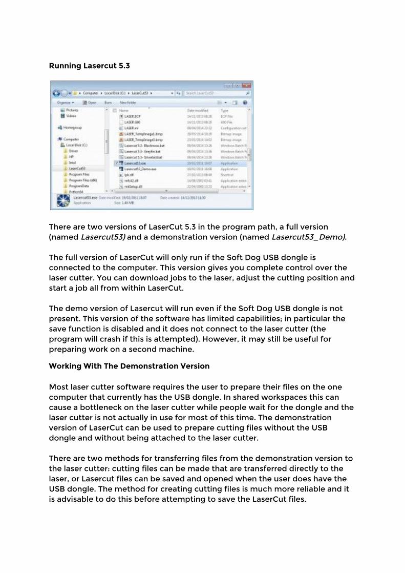
There are two versions of LaserCut 5.3 in the program path, a full version (named Lasercut53) and a demonstration version (named Lasercut53_Demo). The full version of LaserCut will only run if the Soft Dog USB dongle is connected to the computer. This version gives you complete control over the laser cutter. You can download jobs to the laser, adjust the cutting position and start a job all from within LaserCut. The demo version of Lasercut will run even if the Soft Dog USB dongle is not present. This version of the software has limited capabilities; in particular the save function is disabled and it does not connect to the laser cutter (the program will crash if this is attempted). However, it may still be useful for preparing work on a second machine.
Working With The Demonstration Version Most laser cutter software requires the user to prepare their files on the one computer that currently has the USB dongle. In shared workspaces this can cause a bottleneck on the laser cutter while people wait for the dongle and the laser cutter is not actually in use for most of this time. The demonstration version of LaserCut can be used to prepare cutting files without the USB dongle and without being attached to the laser cutter. There are two methods for transferring files from the demonstration version to the laser cutter: cutting files can be made that are transferred directly to the laser, or Lasercut files can be saved and opened when the user does have the USB dongle. The method for creating cutting files is much more reliable and it is advisable to do this before attempting to save the LaserCut files.
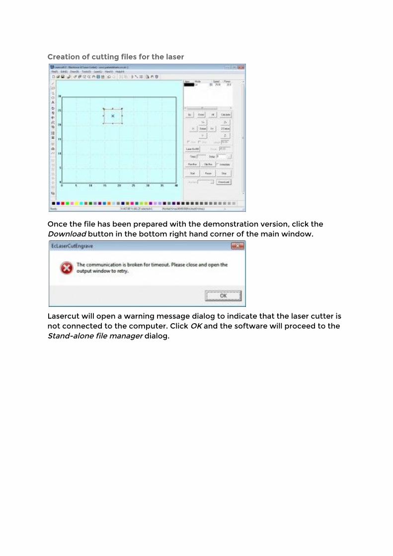
Creation of cutting files for the laser
Once the file has been prepared with the demonstration version, click the Download button in the bottom right hand corner of the main window.
Lasercut will open a warning message dialog to indicate that the laser cutter is not connected to the computer. Click OK and the software will proceed to the Stand-alone file manager dialog.

Click Export file, this creates a series of cutting files. The laser cutter can read these files directly from a USB stick when it is inserted into the USB port on the right side of the machine.
Creation of native LaserCut files
In the demonstration mode the standard save functions have been been disabled, however when the application attempts to exit the user is still presented with an option to save their work. This oversight can be used to create native LaserCut files while running the demonstration version of the program. As mentioned before though it is advisable to create cutting files before trying this because if something does go wrong the application will have exited and the work will be lost.
Basic Drawing Lasercut 5.3 provides the user with a selection of basic drawing functions. These functions are very useful for creating quick drawings or to modify imported items. For more complicated drawings it is recommend that you use a 3rd party program like Inkscape and import the drawing as a DXF file.
Simple Shapes
These functions draw new items on the canvas.
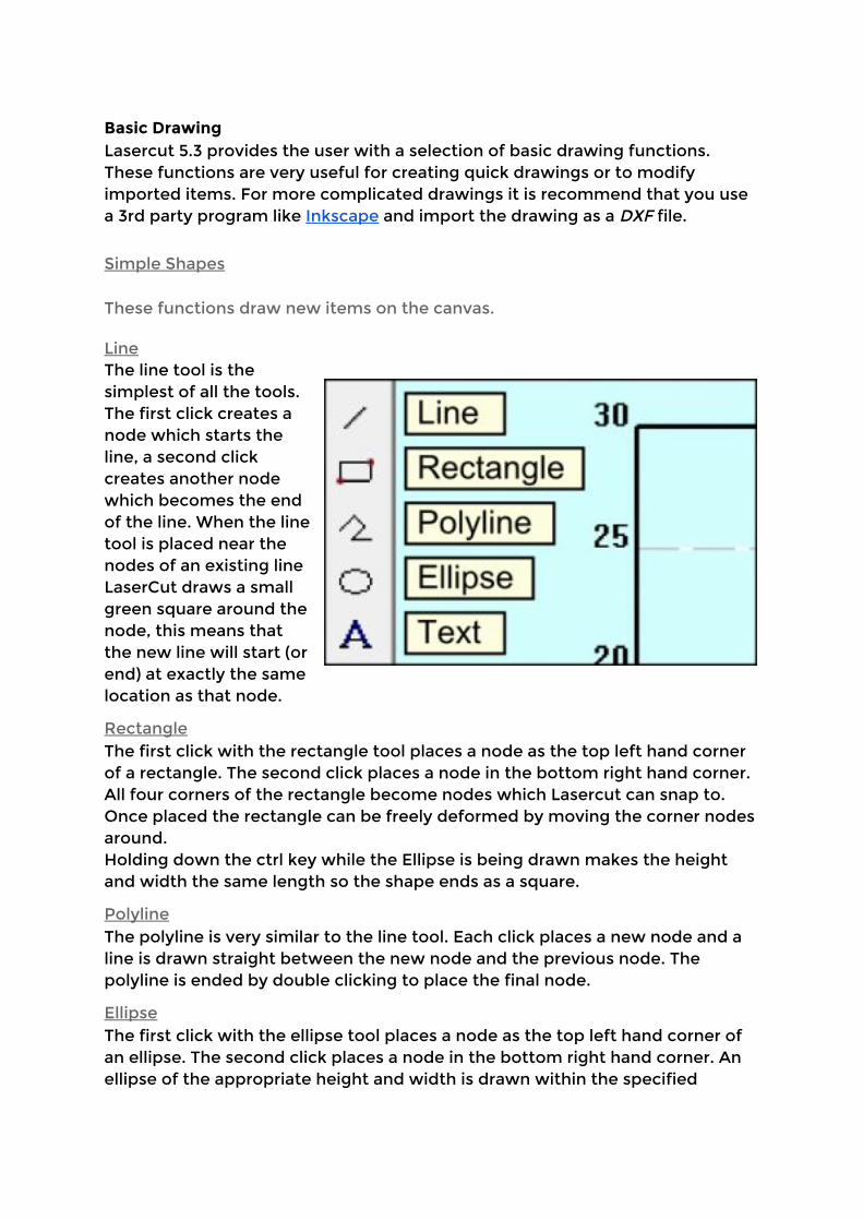
Line The line tool is the simplest of all the tools. The first click creates a node which starts the line, a second click creates another node which becomes the end of the line. When the line tool is placed near the nodes of an existing line LaserCut draws a small green square around the node, this means that the new line will start (or end) at exactly the same location as that node.
Rectangle The first click with the rectangle tool places a node as the top left hand corner of a rectangle. The second click places a node in the bottom right hand corner. All four corners of the rectangle become nodes which Lasercut can snap to. Once placed the rectangle can be freely deformed by moving the corner nodes around. Holding down the ctrl key while the Ellipse is being drawn makes the height and width the same length so the shape ends as a square.
Polyline The polyline is very similar to the line tool. Each click places a new node and a line is drawn straight between the new node and the previous node. The polyline is ended by double clicking to place the final node.
Ellipse The first click with the ellipse tool places a node as the top left hand corner of an ellipse. The second click places a node in the bottom right hand corner. An ellipse of the appropriate height and width is drawn within the specified

rectangle. Holding down the Ctrl key while the rectangle is being drawn makes the height and width the same length so the shape ends as a circle.
Text With the text tool, the user is expected to click and drag to draw a rectangle on the screen. LaserCut then presents the user with the text entry dialog box, the size of the drawn rectangle bears no resemblance to the size of the text created. The numeric values on the form are given in millimetres. Height is the full height of a character should it reach to the top of the line and all the way under the line. Space is the amount of room to leave between each letter. The font is selected from the drop down box, but the user is not provided with a preview as to what the font will look like. The desired text goes in the very bottom text box. If the user has another object selected while creating new text, LaserCut will offer to align the new text to the selected object. This is how to make text follow curves and lines.
Simple Object Modification
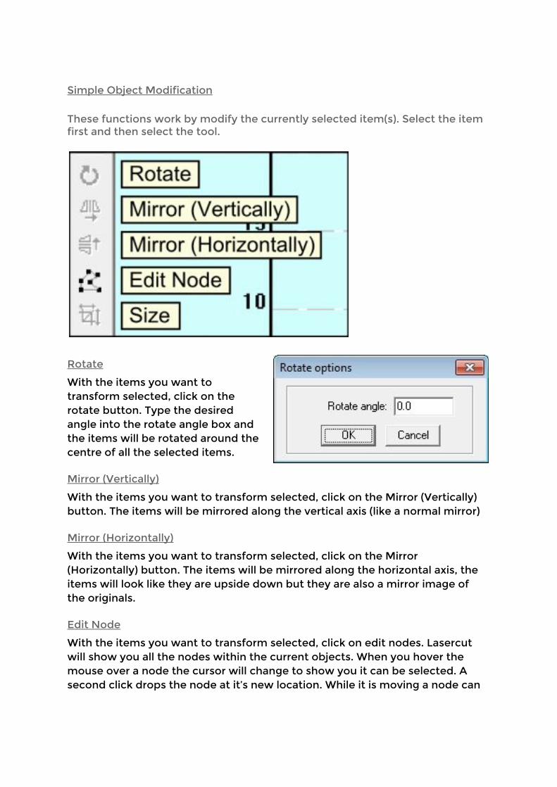
These functions work by modify the currently selected item(s). Select the item first and then select the tool.
Rotate With the items you want to transform selected, click on the rotate button. Type the desired angle into the rotate angle box and the items will be rotated around the centre of all the selected items.
Mirror (Vertically)
With the items you want to transform selected, click on the Mirror (Vertically) button. The items will be mirrored along the vertical axis (like a normal mirror)
Mirror (Horizontally)
With the items you want to transform selected, click on the Mirror (Horizontally) button. The items will be mirrored along the horizontal axis, the items will look like they are upside down but they are also a mirror image of the originals.
Edit Node
With the items you want to transform selected, click on edit nodes. Lasercut will show you all the nodes within the current objects. When you hover the mouse over a node the cursor will change to show you it can be selected. A second click drops the node at it’s new location. While it is moving a node can
be snapped to any of the other nodes within the item and a cyan copy of the item appears allowing you to return the node back to it’s original location.
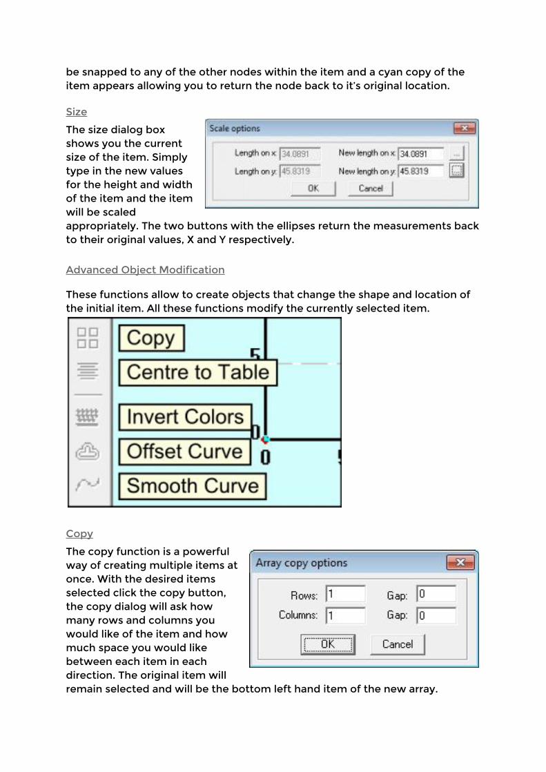
Size The size dialog box shows you the current size of the item. Simply type in the new values for the height and width of the item and the item will be scaled appropriately. The two buttons with the ellipses return the measurements back to their original values, X and Y respectively.
Advanced Object Modification
These functions allow to create objects that change the shape and location of the initial item. All these functions modify the currently selected item.
Copy
The copy function is a powerful way of creating multiple items at once. With the desired items selected click the copy button, the copy dialog will ask how many rows and columns you would like of the item and how much space you would like between each item in each direction. The original item will remain selected and will be the bottom left hand item of the new array.

Centre to Table
With the desired items selected, Centre to Table moves them all to the middle of the work area.
Invert Colors
Invert Colors works on raster images that have been imported into the work area. It does a simple calculation that converts the white pixels to black pixels and vice versa. Lasercut 5.3 does not handle greyscale image, instead it deals with grey colors using a dithering method. Closely spaced dots appear as darker greys and widely spaced dots make up lighter greys.
Offset Curve Offset curves creates a new line around or inside of the selected item (or both). The Corner type setting determines if the new shape should have rounded corners or straight lines. The distance determines how much larger the new shape should be compared to the old one. The Inside/Outside settings determine which lines to draw and the Connect box indicates if the new object should be created as one single item or as a series of separated lines.

Using the Laser Cutter - Workflow • Simple editing in LaserCut • Importing from • Turning on the laser cutter
‣ Cooling 5 mins before ‣ Air assist & extraction when cutting
• Download model to cutter • Datum • Using the focus tool • Visual guide note (might not be exactly where laser cut - how to check
for offset) • Making a test cut • Securing material (weights / magnets) • Positioning for start of cut • Bounding box check w/ test button • Press start • Caution - watch it!

Maintenance
Maintenance schedule
Frequency Task
Weekly Visually inspect the three mirrors lens for dirt or damage. Clean only if necessary
Weekly Remove bed and remove detritus and clean cutting area to prevent a build-up of residue
Weekly Check cooling system: 1. Water in reservoir is clean and free-flowing 2. Check hoses for signs of wear 3. Check pump filter and clean if necessary 4. Laser tube is free of bubbles
Monthly Check alignment and make adjustments if necessary
Monthly Clean the mirrors and lens
Monthly If the cooling system uses tap water, change the water
Monthly Check the extraction system for a built-up of dirt or damage to the hoses
Mirror/Lens Inspection and Cleaning
Tools & Materials: • Mirror release tool • Glasses cleaning cloth • Isopropanol • Cotton buds • Case keys • Z-axis operating handle
Time Needed: 10-30 minutes Each optical element should be removed and inspected in good light for dirt and damage.
● Only handle optical elements by their edges, and handle as seldom as possible to avoid damage to the optical surfaces
Mirrors Access mirror 1 via the rear top access panel (a case key is required to open the panel).
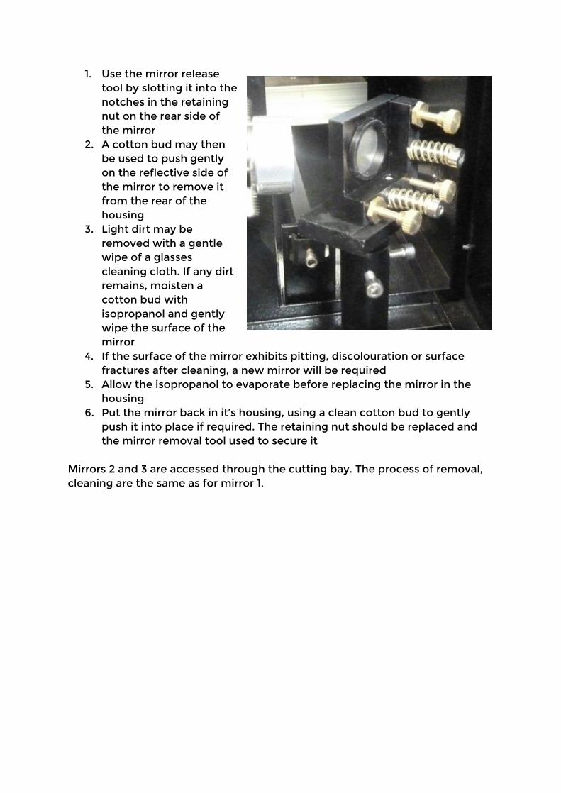
1. Use the mirror release tool by slotting it into the notches in the retaining nut on the rear side of the mirror
2. A cotton bud may then be used to push gently on the reflective side of the mirror to remove it from the rear of the housing
3. Light dirt may be removed with a gentle wipe of a glasses cleaning cloth. If any dirt remains, moisten a cotton bud with isopropanol and gently wipe the surface of the mirror
4. If the surface of the mirror exhibits pitting, discolouration or surface fractures after cleaning, a new mirror will be required
5. Allow the isopropanol to evaporate before replacing the mirror in the housing
6. Put the mirror back in it’s housing, using a clean cotton bud to gently push it into place if required. The retaining nut should be replaced and the mirror removal tool used to secure it
Mirrors 2 and 3 are accessed through the cutting bay. The process of removal, cleaning are the same as for mirror 1.
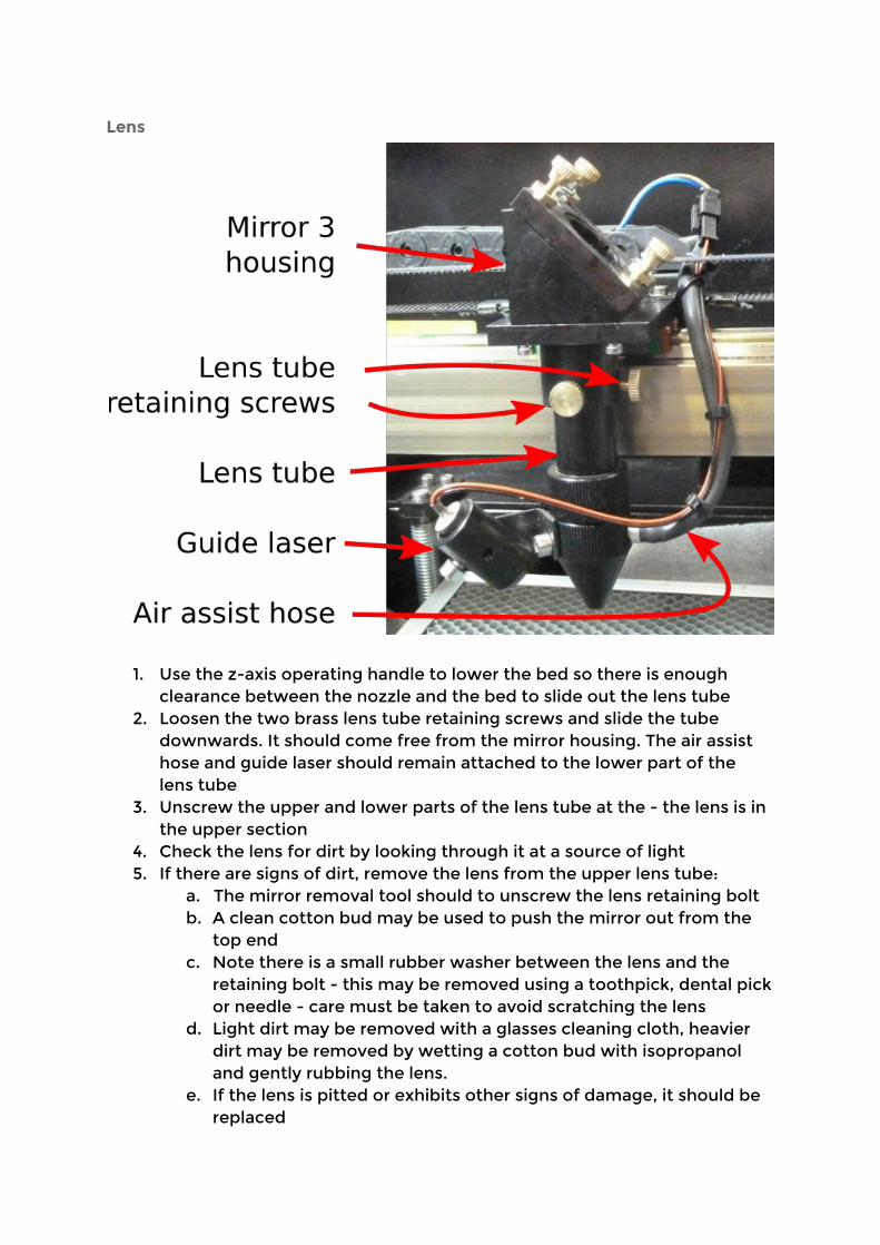
Lens
1. Use the z-axis operating handle to lower the bed so there is enough clearance between the nozzle and the bed to slide out the lens tube
2. Loosen the two brass lens tube retaining screws and slide the tube downwards. It should come free from the mirror housing. The air assist hose and guide laser should remain attached to the lower part of the lens tube
3. Unscrew the upper and lower parts of the lens tube at the - the lens is in the upper section
4. Check the lens for dirt by looking through it at a source of light 5. If there are signs of dirt, remove the lens from the upper lens tube:
a. The mirror removal tool should to unscrew the lens retaining bolt b. A clean cotton bud may be used to push the mirror out from the
top end c. Note there is a small rubber washer between the lens and the
retaining bolt - this may be removed using a toothpick, dental pick or needle - care must be taken to avoid scratching the lens
d. Light dirt may be removed with a glasses cleaning cloth, heavier dirt may be removed by wetting a cotton bud with isopropanol and gently rubbing the lens.
e. If the lens is pitted or exhibits other signs of damage, it should be replaced
6. Allow time for any isopropanol to evaporate and then reassemble the lens tube and place it back in the mirror housing, securing it with the retaining screws
Laser Alignment
Tools Required: • Phillips screwdriver • Masking tape • Mirror release tool
Time Needed: 30 minutes - 3 hours
● Ensure cooling system is running before firing the laser
Overview Working from the laser tube along the optical path to the lens and laser focus, masking tape targets are placed over the various optical elements. The laser is fired to mark the targets and adjustments are made based on the location of the marks at various gantry positions. When all the mirrors are adjusted correctly, the laser beam enters the top of the lens tube parallel to the axis of the tube, and at it’s centre for all positions of the head on both gantries. The lens position is then adjusted until the beam is a tightly focused symmetrical dot at the focal point of the lens The optical path is quite long, and high precision is required. When adjusting the position of mirrors, the tube and the lens, make very small adjustments and re-test the alignment.
Preparation 1. Access to the laser tube compartment at the rear of the machine is
required - move the machine if necessary (take care not to pull out the cooling or air assist hoses)
2. Ensure the water cooling system is running 3. Make at least three masking tape targets, as explained below
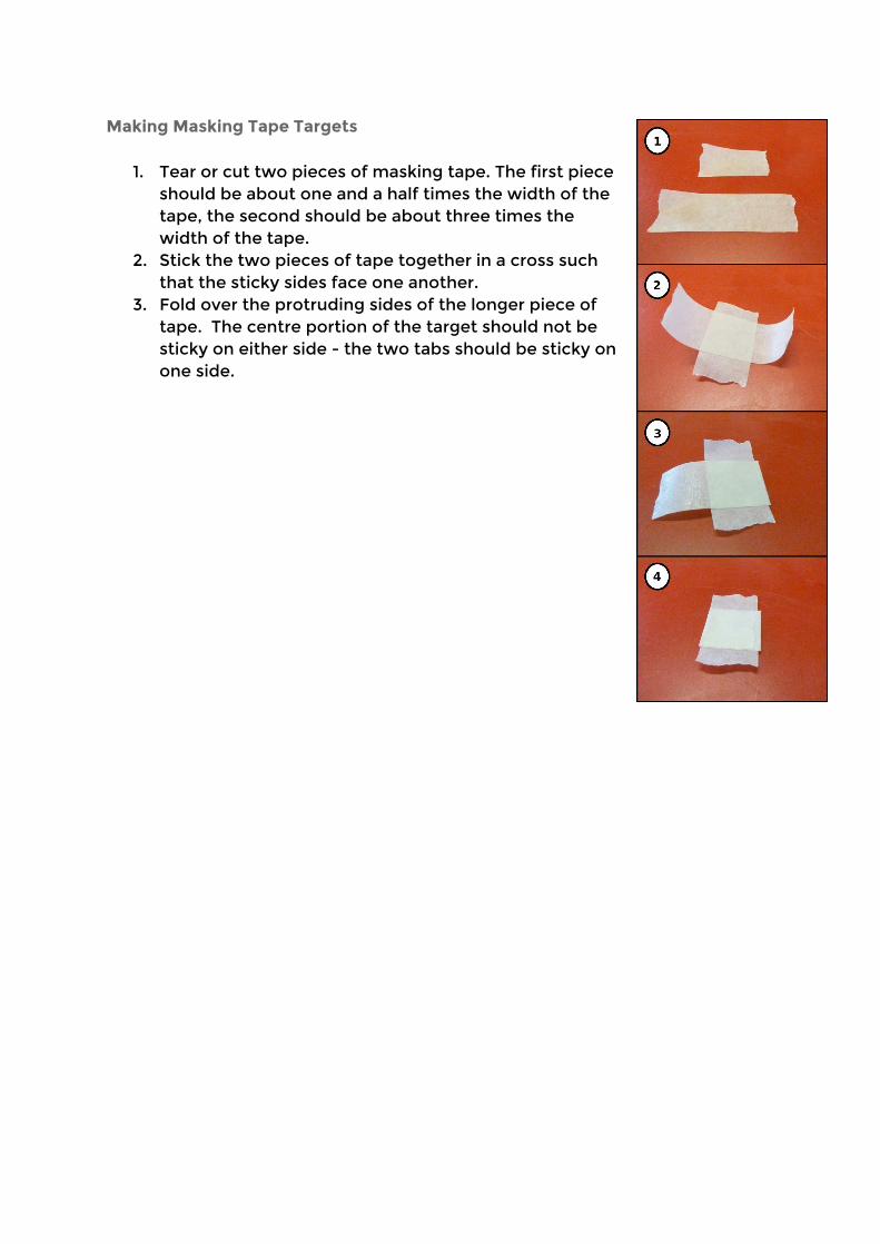
Making Masking Tape Targets
1. Tear or cut two pieces of masking tape. The first piece should be about one and a half times the width of the tape, the second should be about three times the width of the tape.
2. Stick the two pieces of tape together in a cross such that the sticky sides face one another.
3. Fold over the protruding sides of the longer piece of tape. The centre portion of the target should not be sticky on either side - the two tabs should be sticky on one side.
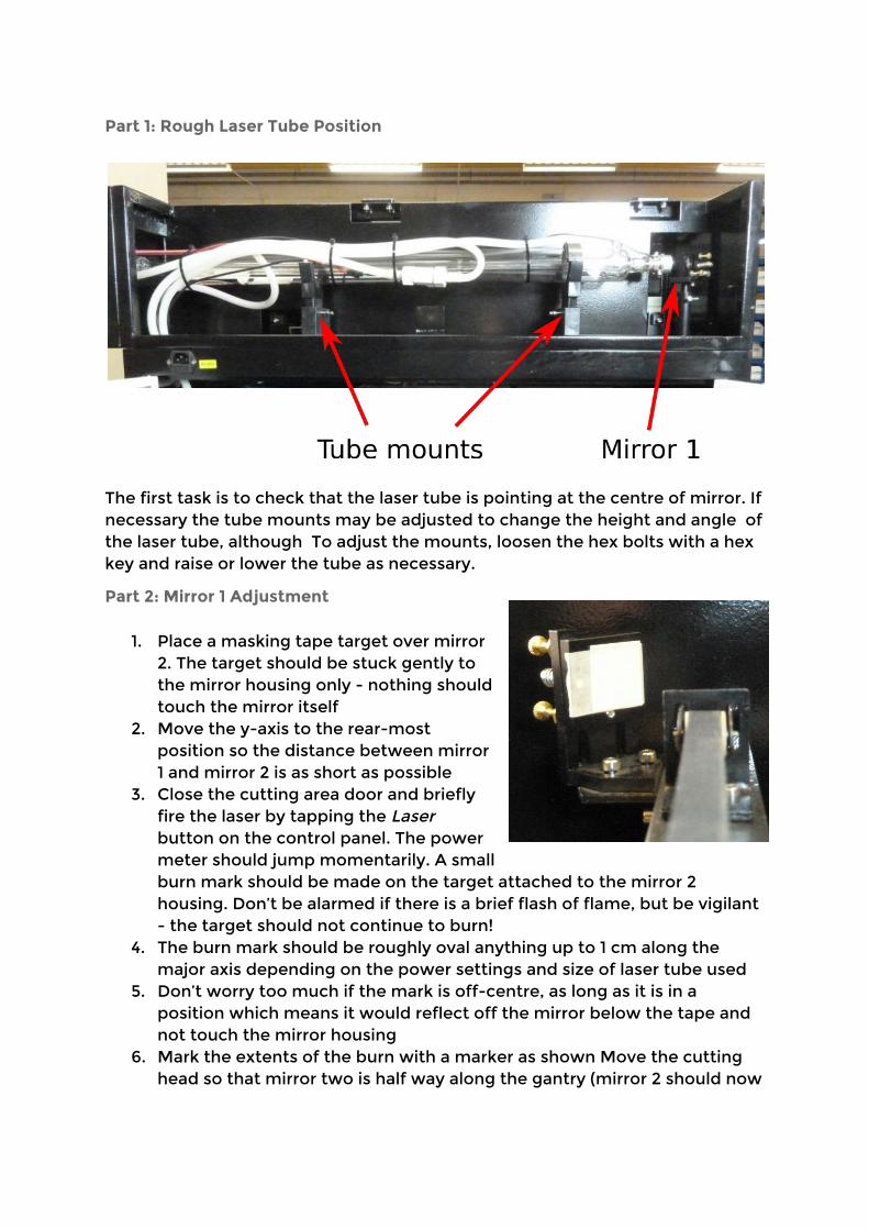
Part 1: Rough Laser Tube Position
The first task is to check that the laser tube is pointing at the centre of mirror. If necessary the tube mounts may be adjusted to change the height and angle of the laser tube, although To adjust the mounts, loosen the hex bolts with a hex key and raise or lower the tube as necessary.
Part 2: Mirror 1 Adjustment
1. Place a masking tape target over mirror 2. The target should be stuck gently to the mirror housing only - nothing should touch the mirror itself
2. Move the y-axis to the rear-most position so the distance between mirror 1 and mirror 2 is as short as possible
3. Close the cutting area door and briefly fire the laser by tapping the Laser button on the control panel. The power meter should jump momentarily. A small burn mark should be made on the target attached to the mirror 2 housing. Don’t be alarmed if there is a brief flash of flame, but be vigilant - the target should not continue to burn!
4. The burn mark should be roughly oval anything up to 1 cm along the major axis depending on the power settings and size of laser tube used
5. Don’t worry too much if the mark is off-centre, as long as it is in a position which means it would reflect off the mirror below the tape and not touch the mirror housing
6. Mark the extents of the burn with a marker as shown Move the cutting head so that mirror two is half way along the gantry (mirror 2 should now
be about half its maximum distance from mirror 1)
7. Stick a new piece of tape over the burn mark (the marker from the first burn should be visible through the tape)
8. Fire the laser again - a second mark should be made. If no new mark is made move the cutting head so as to half the distance between mirrors 1 and 2 and try again
9. If the second mark is not the same place as the first mark, make an adjustment to the position of mirror 1. Adjustments should be small - more more than 1/16th of a turn. If the second mark was too high, turn the top adjuster screw clockwise. If the second mark was to the left of the original mark, turn the bottom-left adjuster screw clockwise. Repeat items 8-10 in this list until the new mark is directly over the original mark
10. Move the cutting head to that mirror two is at the front of the cutting bed (so mirror 2 is as far from mirror 1 as it can be) and repeat items 8-10 until the new mark is directly over the original mark.
Mirror 1 should now be aligned.
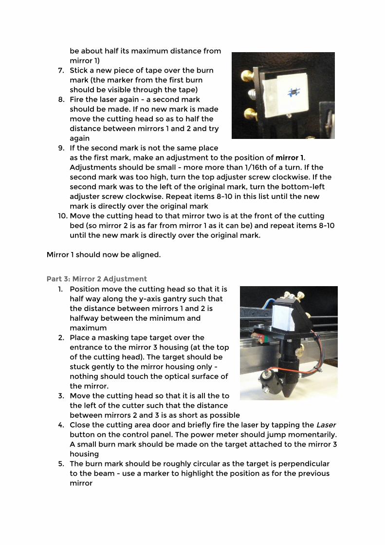
Part 3: Mirror 2 Adjustment 1. Position move the cutting head so that it is
half way along the y-axis gantry such that the distance between mirrors 1 and 2 is halfway between the minimum and maximum
2. Place a masking tape target over the entrance to the mirror 3 housing (at the top of the cutting head). The target should be stuck gently to the mirror housing only - nothing should touch the optical surface of the mirror.
3. Move the cutting head so that it is all the to the left of the cutter such that the distance between mirrors 2 and 3 is as short as possible
4. Close the cutting area door and briefly fire the laser by tapping the Laser button on the control panel. The power meter should jump momentarily. A small burn mark should be made on the target attached to the mirror 3 housing
5. The burn mark should be roughly circular as the target is perpendicular to the beam - use a marker to highlight the position as for the previous mirror
6. Stick a new piece of tape over the burn mark (the marker from the first burn should be visible through the tape)
7. Move the cutting head to the right-most extent and fire the laser again. If no mark appears on the target, halve the distance between mirrors 2 and three and try again (repeat until you see the second mark)
8. Use the adjustment screws on mirror 2 to change the position of the second mark. The top screw will move the mark down if turned clockwise, up if turned anti-clockwise. The screw at the lower right (as viewed from the side with the screw) will move the mark up and left when turned clockwise. The screw at the lower left will move the mark right when turned clockwise. After each small adjustment fire the laser and compare the new mark to the original mark. Repeat until the original and new mark are aligned
9. Check that the burn mark is in the same place when the cutting head is at all four corners of the cutting area, and in the centre
Mirrors 1 and 2 should now be roughly aligned.
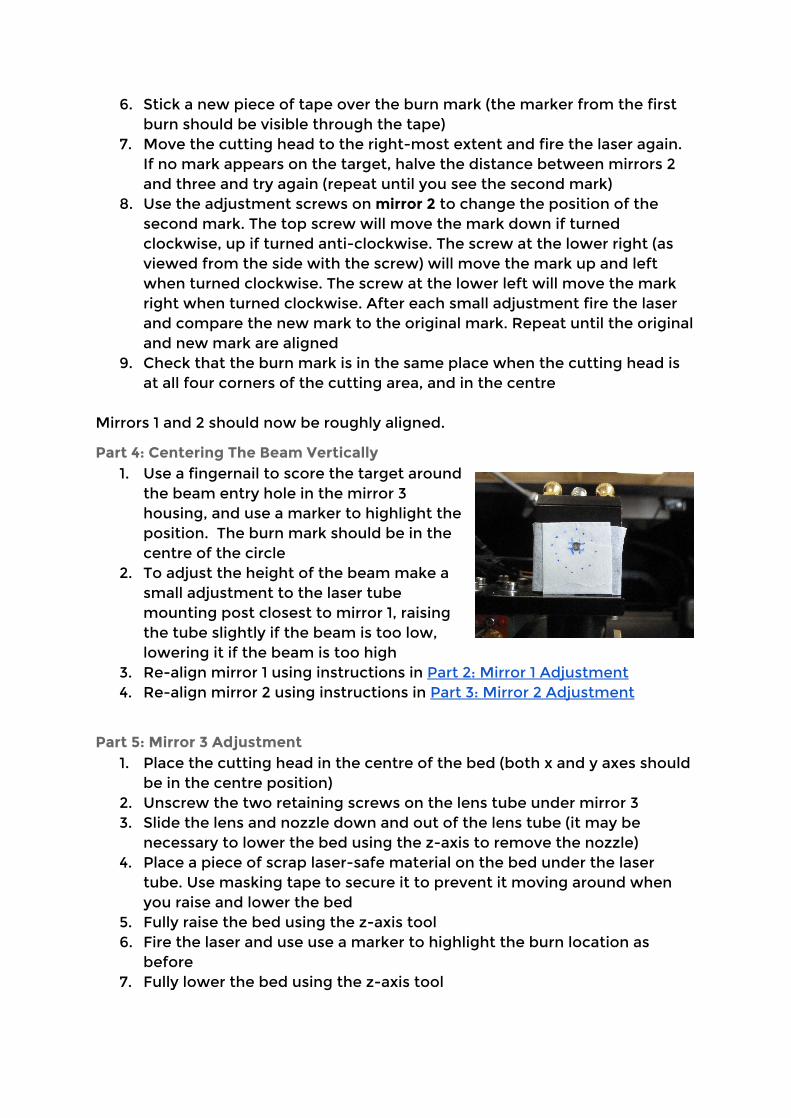
Part 4: Centering The Beam Vertically 1. Use a fingernail to score the target around
the beam entry hole in the mirror 3 housing, and use a marker to highlight the position. The burn mark should be in the centre of the circle
2. To adjust the height of the beam make a small adjustment to the laser tube mounting post closest to mirror 1, raising the tube slightly if the beam is too low, lowering it if the beam is too high
3. Re-align mirror 1 using instructions in Part 2: Mirror 1 Adjustment 4. Re-align mirror 2 using instructions in Part 3: Mirror 2 Adjustment
Part 5: Mirror 3 Adjustment 1. Place the cutting head in the centre of the bed (both x and y axes should
be in the centre position) 2. Unscrew the two retaining screws on the lens tube under mirror 3 3. Slide the lens and nozzle down and out of the lens tube (it may be
necessary to lower the bed using the z-axis to remove the nozzle) 4. Place a piece of scrap laser-safe material on the bed under the laser
tube. Use masking tape to secure it to prevent it moving around when you raise and lower the bed
5. Fully raise the bed using the z-axis tool 6. Fire the laser and use use a marker to highlight the burn location as
before 7. Fully lower the bed using the z-axis tool

8. Fire the laser again, and make adjustments to the screws on mirror three to move the new burn mark exactly over the first burn:
a. Turning the screw on the right side clockwise with move the burn mark to the right
b. Turning the left side front screw clockwise will move the burn and left and towards the front of the cutter
c. Turning the screw on the rear left clockwise will move the burn towards the rear of the cutter and left
9. Move the z-axis to the top-most position and repeat the procedure until the burn marks at both extents of the z-axis are in the same place
10. Replace the nozzle and lens in lens tube and secure with the retaining screws
11. Using the focus tool, adjust the z-axis position so that the laser is focused on the scrap material
12. Move the laser slightly so it is pointing at a clean piece of material and fire it - the resulting burn should be a very small, circular burn mark
Mirrors 1, 2 and 3 should now be properly aligned.

Troubleshooting
Symptom Cause Solution
Laser does not cut (no marks on material)
Lid not fully closed Close the lid
Laser cuts but not all the way through material
Focus incorrect Use the focus tool to set the correct z-axis position
Cutting speed to fast / power too low
Check the settings for the layer is not cutting, and reduce the speed or increase the power
Reduction in power (not cutting material which used to cut with same settings)
Dirty or damaged optics
Visually inspect the mirrors and lens for dirt and/or damage and clean if necessary (see here)
Software does not communicate with cutter (TODO: error messages screenshot?)
TODO: other software error messages