blade n’ bullet blind - cabelas.com cabelas.com or call 1-800-237-4444 for ... (with an attachment...
TRANSCRIPT
Please read this manual in its entirety prior to using this product.Visit cabelas.com or call 1-800-237-4444 for assistance.
Cabela’s Item Number: 466353
BLADE N’ BULLET BLIND

Table of ContentsPackage Contents
Instructions for Use
234-13
TABLE OF CONTENTS
2
TABLE OF CONTENTS
Please read this manual in its entirety prior to using this product.Visit cabelas.com or call 1-800-237-4444 for assistance.
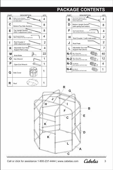
TABLE OF CONTENTS
Call or click for assistance 1-800-237-4444 | www.cabelas.com 3
A
B
C
D
F
G
E
H IJ
K
PACKAGE CONTENTS
A Bottom Corner Sections with attached upright connectors and stake plates
4 BTop Corner Sections with attached upright connectorswithout stake plates
4
C 8Bottom/Top Side SectionsD 8Bottom Upright Section
(with spring lock button)
PART DESCRIPTION QTY PART DESCRIPTION QTY
E 8Top Upright Section (With 5 adjustment holes)
F 4Roof Support Bracket (With an attachment tab on bottom end only)
G 4Roof Support Bracket (With an attachment tab on each end) H 2Roof Coupler 1 (with male ends)
I 2Roof Coupler 2 (With attachment tabs) J 2Roof Peak
K 4 L 7Adjustable Gun Rest/ Support Rail (Long)
Adjustable Gun rest/ Support Rail (Short)
M Knob Bolts22 N-1 M8 x 30mm Bolt
(with washers and lock nuts) 40
N-2 M8 x 35mm Bolt (with washers and lock nuts) 12
N-3 Bolt M8x40(with washers and lock nuts)
4
Bolt M8x15(with washers and lock nuts) 1N-4
O 1Hex Wrench
P 1Open End Wrench
Q Side Cover1
R Roof 1
L
C
R
K

PACKAGE CONTENTS
Please read this manual in its entirety prior to using this product.4
INSTRUCTIONS
STEP 1 | Step 1. Locate the 4- Bottom Corner Sections (A) with attached upright connectors and Stake Plates, along with 4 of the Bottom/Top Side Sections. (C) Fig 1.
Assemble the bottom of the frame by inserting each end of the Bottom/Top Side Sections (C) into each end of the Bottom Corner Sections (A). Be sure the stake plates on the Bottom Corner Sections (A) are positioned to the inside and the attached upright connectors are facing up. Secure the sections together using 8 of the (N1) M8 x 30mm bolts, washers and nuts. Note: To protect the fabric cover always insert the button head bolts from the outside of the frame with the Lock nuts on the inside. Also, hand tighten only all of the connections until all of the frame parts have been assembled. Fig 1.
Fig. 1
A
C
Fig. 1A
N-1
Call or click for assistance 1-800-237-4444 | www.cabelas.com 5
INSTRUCTIONS FOR USE
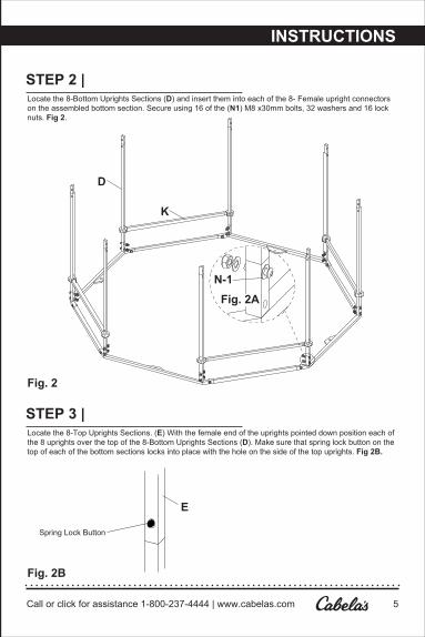
STEP 2 | Locate the 8-Bottom Uprights Sections (D) and insert them into each of the 8- Female upright connectors on the assembled bottom section. Secure using 16 of the (N1) M8 x30mm bolts, 32 washers and 16 lock nuts. Fig 2.
STEP 3 | Locate the 8-Top Uprights Sections. (E) With the female end of the uprights pointed down position each of the 8 uprights over the top of the 8-Bottom Uprights Sections (D). Make sure that spring lock button on the top of each of the bottom sections locks into place with the hole on the side of the top uprights. Fig 2B.
D
Fig. 2
Fig. 2B
Fig. 2A
K
N-1
Spring Lock Button
E
INSTRUCTIONS

Please read this manual in its entirety prior to using this product.6
INSTRUCTIONS FOR USE CONT.
STEP 4 | Locate the 4-Gun Rest/Support Rails (Long) (K), along with 8 of the Knob Bolts (M)
Place the nylon slides that are attached to the ends of the Gun Rest/Support Rails (Long) (K) over the top of the Top Uprights (E). Note: The rails should be centered directly over the section of the bottom frame without the stake plates attached (C) These will be the Gun/Rest Support Rails for the 4 long vertical shooting windows. Fig 2 and 2C.
Note: There are 2- small screw heads on the bottom side each of the rails, be sure they are facing down when installing the rails.
Thread one of the Knob bolts (M) into the threaded hole on front side of each end of the nylon slides. With one hand on each side of the rail push each rail down towards the ground. Fig 2C.
Note: To keep the shooting rails stacked in the correct order, you must complete Step 4 prior to starting on Step 5.
Fig. 2C
Fig. 3
KM
LK
F
D
E
INSTRUCTIONS
DOOR

Call or click for assistance 1-800-237-4444 | www.cabelas.com 7
INSTRUCTIONS FOR USE CONT.
STEP 5 | Locate 4 of the Adjustable Gun Rest/Support Rails (Short) (L), along with 8 -Knob Bolts (M).
Place the nylon slides that are attached to the ends of the Gun Rest/Support Rails (short) (L) over the top of the Top Uprights (E). Note: The rails should be centered directly over the section of the bottom frame with the stake plates attached. (A) These will be the lower Gun/Rest Support Rails for the 3 horizontal shooting windows and the Door support. Fig 3 and 4. Thread the Knob bolts (M) into the threaded holes on the front side of each end of the nylon slides. Fig 2C.
Note: There are 2- small screw heads on the bottom side of the rails, be sure they are facing down when installing these rails.
Fig. 4
Fig. 4AC
B
N-1
N-1
E
D
INSTRUCTIONS

Please read this manual in its entirety prior to using this product.8
INSTRUCTIONS FOR USE CONT.
STEP 6 | Locate the remaining 3 Adjustable Gun Rest/Support Rails (Short) (L), along with 6-Knob Bolts (M).
Center the 3 remaining (L) rails directly over the 3 rails that you just installed for the horizontal windows in Step 6. These will be the top rails for the 3 horizontal shooting windows. Fig 3 and 4. Thread the Knob bolts (M) into the threaded holes on the front side of each end of the nylon slides. Fig 2C.
STEP 7 | Assemble the Top frame by inserting each of the male ends on the Bottom/Top Side Sections (C) into the female ends on each of the Corner Sections (Top) (B). Secure the sections together using 8 of the (N3) M8 x30mm bolts, 16 washers and 8 lock nuts. (Fig. 4A)
STEP 8 | With help from another person, lift the assembled frame top up (with the upright connectors facing down) above the top of the uprights, placing it on top of the 8 uprights, be sure that you line up the Top Corner Sections (B) directly over the Bottom Corner Sections (A). Secure the sections together using 8 of the (N3) M8 x30mm bolts, 16 washers and 8 lock nuts. (Fig. 4 and 4A)
Note: There are 2 sets of holes in the upright connectors, use only the lower set of holes for this step. Fig 4A.
STEP 9 | Step 9. Locate the 4-Roof Support Brackets (F) (With an attachment tab on bottom end only) along with 2 of the Roof Coupler 1’s (H) (With 2-male ends)
Insert each end of one of the Roof couplers into the female ends of each of 2 of the Roof support brackets. Secure using 8 of the (N1) M8 x30mm bolts, 16 washers and 8 lock nuts. Repeat this step with the remaining 2 Roof Support Brackets (F) and Roof Couplers 1 (H). (Fig 5)
Fig. 5
G
F
Fig. 5C Fig. 5A
N-3
IJ
H
Fig. 5BN-4
J
N-2
INSTRUCTIONS

SAFETY AND CARE INSTRUCTIONS
Fig. 6
Fig. 6A
INSTRUCTIONS
Please read this manual in its entirety prior to using this product.10

INSTRUCTIONS
STEP 2 | Attaching the Fabric Side Cover and RoofFrom the inside of the blind locate the 8 shock corded S-Hooks that are sewn into the top and bottom of the fabric side cover. Stretch the shock cord over the top of the blind frame and insert the S-Hooks into the vertical slots that are cut in the frame uprights. (Fig. 7A) Repeat the above step on the bottom by having your helper lift up the bottom of the frame while you stretch the shock cord around the bottom of the frame securing the S-Hook in its slot on the lower uprights.
STEP 3 | Attaching the Fabric Side Cover and RoofWith the help of another person lift the waterproof roof over the top of the blind frame, rotate the roof cover around the frame until the air vents on the roof are centered above the long Vertical shooting windows and the attachment buckles and straps on the inside walls of the blind are aligned. Once aligned pull the edges of the roof down over the top of the fabric sides until it is tight. (Fig. 8) Then from the inside connect the 4 buckles sewn into the roof cover to the 4 buckles that are sewn to the inside of the fabric side cover. Once connected pull the strap tight to secure the roof to the fabric side walls.
Fig. 8
Please read this manual in its entirety prior to using this product.12
Call or click for assistance 1-800-237-4444 | www.cabelas.com 9
SAFETY AND CARE INSTRUCTIONS
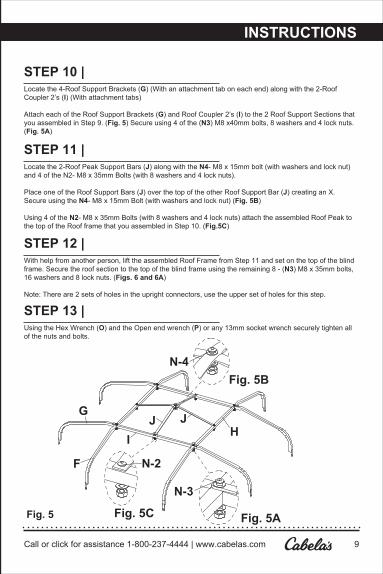
STEP 10 | Locate the 4-Roof Support Brackets (G) (With an attachment tab on each end) along with the 2-Roof Coupler 2’s (I) (With attachment tabs)
Attach each of the Roof Support Brackets (G) and Roof Coupler 2’s (I) to the 2 Roof Support Sections that you assembled in Step 9. (Fig. 5) Secure using 4 of the (N3) M8 x40mm bolts, 8 washers and 4 lock nuts. (Fig. 5A)
STEP 11 | Locate the 2-Roof Peak Support Bars (J) along with the N4- M8 x 15mm bolt (with washers and lock nut) and 4 of the N2- M8 x 35mm Bolts (with 8 washers and 4 lock nuts).
Place one of the Roof Support Bars (J) over the top of the other Roof Support Bar (J) creating an X. Secure using the N4- M8 x 15mm Bolt (with washers and lock nut) (Fig. 5B)
Using 4 of the N2- M8 x 35mm Bolts (with 8 washers and 4 lock nuts) attach the assembled Roof Peak to the top of the Roof frame that you assembled in Step 10. (Fig.5C)
STEP 12 | With help from another person, lift the assembled Roof Frame from Step 11 and set on the top of the blind frame. Secure the roof section to the top of the blind frame using the remaining 8 - (N3) M8 x 35mm bolts, 16 washers and 8 lock nuts. (Figs. 6 and 6A)
Note: There are 2 sets of holes in the upright connectors, use the upper set of holes for this step.
STEP 13 | Using the Hex Wrench (O) and the Open end wrench (P) or any 13mm socket wrench securely tighten all of the nuts and bolts.
Fig. 5
G
F
Fig. 5C Fig. 5A
N-3
IJ
H
Fig. 5BN-4
J
N-2
INSTRUCTIONS

Call or click for assistance 1-800-237-4444 | www.cabelas.com 11
INSTRUCTIONS
STEP 1 | Attaching the Fabric Side Cover and RoofWith the help of another person roll out the fabric side cover and find the door section. (The door section has the Cabela’s logo printed on it) With one person holding the zippered edge near the door and the other person holding the opposite zippered edge wrap the fabric around the frame being sure to keep the door centered in it section at the back of frame. With each person pulling the fabric ends together, connect the two ends using the long vertical zipper. Note: The fabric side cover is design to fit tightly around the blind frame so it will take both people working together to pull the ends together and get the zipper closed. It is recommended that once you have the zipper started, one person pulls on the zipper while the other pulls the two ends together just below the zipper pull. (Fig. 7)
Q
Fig. 7A
Fig. 7
Call or click for assistance 1-800-237-4444 | www.cabelas.com 13
INSTRUCTIONS
To return or exchange an item at one of our retail locations, please present a validphoto I.D. which will be recorded to authorize returns. Cabela’s reserves the right toaddress abuse of this policy and/or deny returns or exchanges. Other restrictions may apply. Please visit www.cabelas.com, visit your local retail store, or call 1.800.237.4444 for additional information.
STEP 1 | Adjusting the Gun Rest/ Support RailsThe height of the Gun Rest/ Support rails as well as the height of the window openings can easily be adjusted by loosening the Knob Bolts (M) and positioning the rails up or down, then simply retighten the Knob bolts. Note: Always use 2 hands (one on each side of the rail) to move the rail up and down trying to kept the rail in a level position to keep it from binding. You will notice that there are 5 holes at the bottom and one hole about 8” from the top of each of the Top upright section. These holes are used to position each rail at the same height. The upper hole should be used to positon the top rail on each of the 3 Horizontal windows and above the Door. Fig 6. Although the lower rails as well as the single rails on the long vertical windows can be set at any height, the 5 holes at the bottom of the top uprights can be used to lock the rails solid in place. Note: The Spring Button that is used to lock the upper and lower uprights sections together, will also move in out clearing the way when positioning the rails down to the lower portion of the bottom uprights, giving the clearance needed to use the long vertical windows for shooting a bow.