blade system design studies phase ii: final project...
TRANSCRIPT
SANDIA REPORT SAND2008-4648 Unlimited Release Printed July 2008
Blade System Design Studies Phase II: Final Project Report Derek S. Berry Prepared by Sandia National Laboratories Albuquerque, New Mexico 87185 and Livermore, California 94550 Sandia is a multiprogram laboratory operated by Sandia Corporation, a Lockheed Martin Company, for the United States Department of Energy’s National Nuclear Security Administration under Contract DE-AC04-94AL85000. Approved for public release; further dissemination unlimited.

2
Issued by Sandia National Laboratories, operated for the United States Department of Energy by Sandia Corporation. NOTICE: This report was prepared as an account of work sponsored by an agency of the United States Government. Neither the United States Government, nor any agency thereof, nor any of their employees, nor any of their contractors, subcontractors, or their employees, make any warranty, express or implied, or assume any legal liability or responsibility for the accuracy, completeness, or usefulness of any information, apparatus, product, or process disclosed, or represent that its use would not infringe privately owned rights. Reference herein to any specific commercial product, process, or service by trade name, trademark, manufacturer, or otherwise, does not necessarily constitute or imply its endorsement, recommendation, or favoring by the United States Government, any agency thereof, or any of their contractors or subcontractors. The views and opinions expressed herein do not necessarily state or reflect those of the United States Government, any agency thereof, or any of their contractors. Printed in the United States of America. This report has been reproduced directly from the best available copy. Available to DOE and DOE contractors from U.S. Department of Energy Office of Scientific and Technical Information P.O. Box 62 Oak Ridge, TN 37831 Telephone: (865) 576-8401 Facsimile: (865) 576-5728 E-Mail: [email protected] Online ordering: http://www.osti.gov/bridge Available to the public from U.S. Department of Commerce National Technical Information Service 5285 Port Royal Rd. Springfield, VA 22161 Telephone: (800) 553-6847 Facsimile: (703) 605-6900 E-Mail: [email protected] Online order: http://www.ntis.gov/help/ordermethods.asp?loc=7-4-0#online
3
SAND2008-4648 Unlimited Release Printed July 2008
Blade System Design Studies Phase II:
Final Project Report
Derek S. Berry TPI Composites, Inc.
373 Market Street Warren, RI 02885
Abstract
This report details the work completed under Phase II of the Sandia National Laboratories Blade System Design Study blade design and manufacturing project; an integrated 9 meter blade design, tooling design and manufacturing, assembly fixture design and fabrication, blade production, blade instrumentation and blade shipping. This project successfully demonstrated the design and manufacturing of a wind turbine blade integrating several innovations including flatback airfoils on inboard blade stations, a carbon fiber spar cap and an iterative blade design process. Flatback airfoils differ from truncated airfoils and offer the structural benefits of thicker sections without large aerodynamic losses. Although the concept of using carbon fiber for a spar cap had been considered by TPI before, this is the first instance in which details such as the best architecture of carbon fabric for infusibility and for load transfer, the optimal method to transition a carbon spar cap into the blade root and the manufacturing issues of handling, cutting and infusing carbon fiber have been worked out. The design approach used for this project demonstrated the myriad advantages of integrating the aerodynamic design, structural design and manufacturing efforts into an iterative process that sought to maximize the strengths of each area without detracting from the others. Following a detailed integrated design of the blade, TPI designed and produced production molds and assembly fixtures for this blade, culminated in the production, instrumentation and shipping of seven BSDS prototype blades. The resulting blade proved to be easier and cheaper to build, as well as lighter, compared with prior 9 meter blade designs.

4
Acknowledgements This project was supported by Sandia National Laboratories under Contract 15890 – Revision 4. The technical monitor was Dale Berg. The author would like to thank Thomas Ashwill, Paul Veers, Mark Rumsey, Dale Berg, Jose Zayas and Daniel Laird at Sandia for their guidance. The author would also like to thank Mike Zuteck at MDZ Consulting, Case van Dam at the University of California – Davis, Kevin Jackson at Dynamic Design and Stephen Nolet at TPI Composites for their help in completing this project.

5
Table of Contents Acknowledgements .. . . . . . . . . . . . . . . . . . . . . . . . . . . . . . . . . . . . . . . . . . . . . . . . . . . . . . . . . . . . . . . . . . . . . . . . . . . . . . . 4
Table of Contents .. . . . . . . . . . . . . . . . . . . . . . . . . . . . . . . . . . . . . . . . . . . . . . . . . . . . . . . . . . . . . . . . . . . . . . . . . . . . . . . . . 5
List of Figures .. . . . . . . . . . . . . . . . . . . . . . . . . . . . . . . . . . . . . . . . . . . . . . . . . . . . . . . . . . . . . . . . . . . . . . . . . . . . . . . . . . . . . . 6
Summary ... . . . . . . . . . . . . . . . . . . . . . . . . . . . . . . . . . . . . . . . . . . . . . . . . . . . . . . . . . . . . . . . . . . . . . . . . . . . . . . . . . . . . . . . . . . 11
1.0 Aerodynamic Analysis of Flatback Airfoils . . . . . . . . . . . . . . . . . . . . . . . . . . . . . . . . . . 13
2.0 BSDS Integrated Blade Design .. . . . . . . . . . . . . . . . . . . . . . . . . . . . . . . . . . . . . . . . . . . . . . . . . . . . 15 2.1 Design Objectives .. . . . . . . . . . . . . . . . . . . . . . . . . . . . . . . . . . . . . . . . . . . . . . . . . . . . . . . . . . . . . . . . . . . . . 15 2.2 Preliminary Design Assumptions .. . . . . . . . . . . . . . . . . . . . . . . . . . . . . . . . . . . . . . . . . . . . . . . . 16 2.3 Blade Design Workflow ... . . . . . . . . . . . . . . . . . . . . . . . . . . . . . . . . . . . . . . . . . . . . . . . . . . . . . . . . . . . 17 2.4 Blade Preliminary Design .. . . . . . . . . . . . . . . . . . . . . . . . . . . . . . . . . . . . . . . . . . . . . . . . . . . . . . . . . . 18 2.5 Blade Structural Design .. . . . . . . . . . . . . . . . . . . . . . . . . . . . . . . . . . . . . . . . . . . . . . . . . . . . . . . . . . . . . 28 2.6 Blade Computer Model . . . . . . . . . . . . . . . . . . . . . . . . . . . . . . . . . . . . . . . . . . . . . . . . . . . . . . . . . . . . . . . 29 2.7 Blade Buckling Analysis . . . . . . . . . . . . . . . . . . . . . . . . . . . . . . . . . . . . . . . . . . . . . . . . . . . . . . . . . . . . . 39 2.8 Blade Frequencies .. . . . . . . . . . . . . . . . . . . . . . . . . . . . . . . . . . . . . . . . . . . . . . . . . . . . . . . . . . . . . . . . . . . . . 40 2.9 Blade Laminate Schedule .. . . . . . . . . . . . . . . . . . . . . . . . . . . . . . . . . . . . . . . . . . . . . . . . . . . . . . . . . . . 40 2.10 Blade Bill of Material . . . . . . . . . . . . . . . . . . . . . . . . . . . . . . . . . . . . . . . . . . . . . . . . . . . . . . . . . . . . . . 43 2.11 Blade Work Instructions .. . . . . . . . . . . . . . . . . . . . . . . . . . . . . . . . . . . . . . . . . . . . . . . . . . . . . . . . . 45
3.0 BSDS Tooling .. . . . . . . . . . . . . . . . . . . . . . . . . . . . . . . . . . . . . . . . . . . . . . . . . . . . . . . . . . . . . . . . . . . . . . . . . . . . . 47 3.1 BSDS Plugs .. . . . . . . . . . . . . . . . . . . . . . . . . . . . . . . . . . . . . . . . . . . . . . . . . . . . . . . . . . . . . . . . . . . . . . . . . . . . . . 47 3.2 BSDS Molds .. . . . . . . . . . . . . . . . . . . . . . . . . . . . . . . . . . . . . . . . . . . . . . . . . . . . . . . . . . . . . . . . . . . . . . . . . . . . . 54 3.3 BSDS Root Stud Positioning Fixture .. . . . . . . . . . . . . . . . . . . . . . . . . . . . . . . . . . . . . . . . . . . 58 3.4 BSDS Blade Assembly Fixture .. . . . . . . . . . . . . . . . . . . . . . . . . . . . . . . . . . . . . . . . . . . . . . . . . . . 61
4.0 BSDS Blade Manufacturing .. . . . . . . . . . . . . . . . . . . . . . . . . . . . . . . . . . . . . . . . . . . . . . . . . . . . . . . . 63 4.1 BSDS Root Threaded Inserts . . . . . . . . . . . . . . . . . . . . . . . . . . . . . . . . . . . . . . . . . . . . . . . . . . . . . . . 63 4.2 BSDS Root Plates .. . . . . . . . . . . . . . . . . . . . . . . . . . . . . . . . . . . . . . . . . . . . . . . . . . . . . . . . . . . . . . . . . . . . . 64 4.3 BSDS Pattern Cutting .. . . . . . . . . . . . . . . . . . . . . . . . . . . . . . . . . . . . . . . . . . . . . . . . . . . . . . . . . . . . . . . . 65 4.4 BSDS Material Lay-Up ... . . . . . . . . . . . . . . . . . . . . . . . . . . . . . . . . . . . . . . . . . . . . . . . . . . . . . . . . . . . . 66 4.5 BSDS Infusion .. . . . . . . . . . . . . . . . . . . . . . . . . . . . . . . . . . . . . . . . . . . . . . . . . . . . . . . . . . . . . . . . . . . . . . . . . . 72 4.6 BSDS Blade Assembly.. . . . . . . . . . . . . . . . . . . . . . . . . . . . . . . . . . . . . . . . . . . . . . . . . . . . . . . . . . . . . . . 74 4.7 BSDS Blade Finishing .. . . . . . . . . . . . . . . . . . . . . . . . . . . . . . . . . . . . . . . . . . . . . . . . . . . . . . . . . . . . . . . 77 4.8 BSDS Instrumentation .. . . . . . . . . . . . . . . . . . . . . . . . . . . . . . . . . . . . . . . . . . . . . . . . . . . . . . . . . . . . . . . 80
5.0 BSDS Blade Shipping .. . . . . . . . . . . . . . . . . . . . . . . . . . . . . . . . . . . . . . . . . . . . . . . . . . . . . . . . . . . . . . . . . 82
6.0 Conclusion .. . . . . . . . . . . . . . . . . . . . . . . . . . . . . . . . . . . . . . . . . . . . . . . . . . . . . . . . . . . . . . . . . . . . . . . . . . . . . . . . . 84
7.0 References.. . . . . . . . . . . . . . . . . . . . . . . . . . . . . . . . . . . . . . . . . . . . . . . . . . . . . . . . . . . . . . . . . . . . . . . . . . . . . . . . . . 85

6
List of Figures Figure 1 – Preliminary Blade Input Data .. . . . . . . . . . . . . . . . . . . . . . . . . . . . . . . . . . . . . . . . . . . . . . . . 18
Figure 2 – Preliminary Blade Input Data .. . . . . . . . . . . . . . . . . . . . . . . . . . . . . . . . . . . . . . . . . . . . . . . . 19
Figure 3 – Preliminary Blade Input Data .. . . . . . . . . . . . . . . . . . . . . . . . . . . . . . . . . . . . . . . . . . . . . . . . 19
Figure 4 – Preliminary Blade Input Data .. . . . . . . . . . . . . . . . . . . . . . . . . . . . . . . . . . . . . . . . . . . . . . . . 20
Figure 5 – Preliminary Operational Model Output Data .. . . . . . . . . . . . . . . . . . . . . . . . . . . 20
Figure 6 – Preliminary Operational Model Output Data .. . . . . . . . . . . . . . . . . . . . . . . . . . . 21
Figure 7 – 9 Meter Blade Root Size Advantages.. . . . . . . . . . . . . . . . . . . . . . . . . . . . . . . . . . . . . . 21
Figure 8 – Flatback Airfoil Sections for Inboard Section .. . . . . . . . . . . . . . . . . . . . . . . . . 24
Figure 9 – S830 Outboard Airfoil . . . . . . . . . . . . . . . . . . . . . . . . . . . . . . . . . . . . . . . . . . . . . . . . . . . . . . . . . . . 25
Figure 10 – S831 Outboard Airfoil . . . . . . . . . . . . . . . . . . . . . . . . . . . . . . . . . . . . . . . . . . . . . . . . . . . . . . . . . 25
Figure 11 – Cross Section Drawing of CX-100 / TX-100 Threaded Root Insert. . . . . . . . . . . . . . . . . . . . . . . . . . . . . . . . . . . . . . . . . . . . . . . . . . . . . . . . . . . . . . . . . . . . . . . . . . . . . . . . . . . . . . . . . . . . . . . . . . . . . . . . . . . 26
Figure 12 – Root Face Geometry for CX-100 and TX-100 Blades .. . . . . . . . . . . . . 26
Figure 13 – Cross Section of Embedded Root Fastener .. . . . . . . . . . . . . . . . . . . . . . . . . . . . 27
Figure 14 – Root Rod Nominal Stress and Endurance Strengths .. . . . . . . . . . . . . . . . 27
Figure 15 – Internal Structural Design – Blade Station 25% (r/R) .. . . . . . . . . . . . . 29
Figure 16 – Blade Model Geometry Details – Revision A... . . . . . . . . . . . . . . . . . . . . . . . 29
Figure 17 – Original Airfoil Sections – Root View ... . . . . . . . . . . . . . . . . . . . . . . . . . . . . . . . . 30
Figure 18 – First Pass Loft of BSDS Blade .. . . . . . . . . . . . . . . . . . . . . . . . . . . . . . . . . . . . . . . . . . . . . 31
Figure 19 – First Pass Loft of BSDS Blade .. . . . . . . . . . . . . . . . . . . . . . . . . . . . . . . . . . . . . . . . . . . . . 31
Figure 20 – Intermediate Loft of BSDS Blade .. . . . . . . . . . . . . . . . . . . . . . . . . . . . . . . . . . . . . . . . . 32
Figure 21 – Intermediate Loft of BSDS Blade .. . . . . . . . . . . . . . . . . . . . . . . . . . . . . . . . . . . . . . . . . 32
Figure 22 – Intermediate Loft of BSDS Blade .. . . . . . . . . . . . . . . . . . . . . . . . . . . . . . . . . . . . . . . . . 33
Figure 23 – Blade Model Geometry Details – Twist Added .. . . . . . . . . . . . . . . . . . . . . . 33

7
Figure 24 – Twisted Airfoil Sections – Root View ... . . . . . . . . . . . . . . . . . . . . . . . . . . . . . . . . 34
Figure 25 – Blade Loft with Twisted Airfoil Sections .. . . . . . . . . . . . . . . . . . . . . . . . . . . . . . 34
Figure 26 – Check Planes for Flatback Geometry .. . . . . . . . . . . . . . . . . . . . . . . . . . . . . . . . . . . . 35
Figure 27 – Check Planes for Flatback Geometry .. . . . . . . . . . . . . . . . . . . . . . . . . . . . . . . . . . . . 35
Figure 28 – Lofted Surface Planar Cuts .. . . . . . . . . . . . . . . . . . . . . . . . . . . . . . . . . . . . . . . . . . . . . . . . . . 36
Figure 29 – Flatback Section Contour Lines .. . . . . . . . . . . . . . . . . . . . . . . . . . . . . . . . . . . . . . . . . . . 36
Figure 30 – Final BSDS Computer Model .. . . . . . . . . . . . . . . . . . . . . . . . . . . . . . . . . . . . . . . . . . . . . . . 37
Figure 31 – Final BSDS Computer Model .. . . . . . . . . . . . . . . . . . . . . . . . . . . . . . . . . . . . . . . . . . . . . . . 37
Figure 32 – Final BSDS Computer Model .. . . . . . . . . . . . . . . . . . . . . . . . . . . . . . . . . . . . . . . . . . . . . . . 38
Figure 33 – Final BSDS Computer Model .. . . . . . . . . . . . . . . . . . . . . . . . . . . . . . . . . . . . . . . . . . . . . . . 38
Figure 34 – Final BSDS Computer Model .. . . . . . . . . . . . . . . . . . . . . . . . . . . . . . . . . . . . . . . . . . . . . . . 39
Figure 35 – BSDS Blade First Frequencies .. . . . . . . . . . . . . . . . . . . . . . . . . . . . . . . . . . . . . . . . . . . . . 40
Figure 36 – Material List for BSDS Blade .. . . . . . . . . . . . . . . . . . . . . . . . . . . . . . . . . . . . . . . . . . . . . . 41
Figure 37 – BSDS Skin Laminate Schedule.. . . . . . . . . . . . . . . . . . . . . . . . . . . . . . . . . . . . . . . . . . . . . 41
Figure 38 – BSDS Flatback Panel Laminate Schedule .. . . . . . . . . . . . . . . . . . . . . . . . . . . . . . 42
Figure 39 – BSDS Shear Web Laminate Schedule .. . . . . . . . . . . . . . . . . . . . . . . . . . . . . . . . . . . . 42
Figure 40 – Fiber Volume Calculations – 3/4oz Mat .. . . . . . . . . . . . . . . . . . . . . . . . . . . . . . . . 43
Figure 41 – BSDS Blade Laminate and Assembly Specifications .. . . . . . . . . . . . . . 43
Figure 42 – Ply Build Up for the BSDS Shear Web ... . . . . . . . . . . . . . . . . . . . . . . . . . . . . . . . 44
Figure 43 – BSDS Blade Bonding Analysis. . . . . . . . . . . . . . . . . . . . . . . . . . . . . . . . . . . . . . . . . . . . . . 44
Figure 44 – BSDS Blade Root Hardware Analysis . . . . . . . . . . . . . . . . . . . . . . . . . . . . . . . . . . . . 44
Figure 45 – BSDS Skin Work Instruction .. . . . . . . . . . . . . . . . . . . . . . . . . . . . . . . . . . . . . . . . . . . . . . . 45
Figure 46 – BSDS Skin Work Instruction .. . . . . . . . . . . . . . . . . . . . . . . . . . . . . . . . . . . . . . . . . . . . . . . 45
Figure 47 – BSDS Skin Work Instruction .. . . . . . . . . . . . . . . . . . . . . . . . . . . . . . . . . . . . . . . . . . . . . . . 46
Figure 48 – BSDS Shear Web Work Instruction .. . . . . . . . . . . . . . . . . . . . . . . . . . . . . . . . . . . . . . 46
8
Figure 49 – BSDS Skin Plug .. . . . . . . . . . . . . . . . . . . . . . . . . . . . . . . . . . . . . . . . . . . . . . . . . . . . . . . . . . . . . . . . . 48
Figure 50 – BSDS Skin Plug .. . . . . . . . . . . . . . . . . . . . . . . . . . . . . . . . . . . . . . . . . . . . . . . . . . . . . . . . . . . . . . . . . 49
Figure 51 – BSDS Skin Plug .. . . . . . . . . . . . . . . . . . . . . . . . . . . . . . . . . . . . . . . . . . . . . . . . . . . . . . . . . . . . . . . . . 49
Figure 52 – BSDS Skin Plug .. . . . . . . . . . . . . . . . . . . . . . . . . . . . . . . . . . . . . . . . . . . . . . . . . . . . . . . . . . . . . . . . . 50
Figure 53 – BSDS Skin Plug .. . . . . . . . . . . . . . . . . . . . . . . . . . . . . . . . . . . . . . . . . . . . . . . . . . . . . . . . . . . . . . . . . 50
Figure 54 – BSDS Skin Plug .. . . . . . . . . . . . . . . . . . . . . . . . . . . . . . . . . . . . . . . . . . . . . . . . . . . . . . . . . . . . . . . . . 51
Figure 55 – BSDS Skin Plug .. . . . . . . . . . . . . . . . . . . . . . . . . . . . . . . . . . . . . . . . . . . . . . . . . . . . . . . . . . . . . . . . . 51
Figure 56 – BSDS Skin Plug .. . . . . . . . . . . . . . . . . . . . . . . . . . . . . . . . . . . . . . . . . . . . . . . . . . . . . . . . . . . . . . . . . 52
Figure 57 – BSDS Skin Plug .. . . . . . . . . . . . . . . . . . . . . . . . . . . . . . . . . . . . . . . . . . . . . . . . . . . . . . . . . . . . . . . . . 52
Figure 58 – BSDS Twisted Shear Web Plug .. . . . . . . . . . . . . . . . . . . . . . . . . . . . . . . . . . . . . . . . . . . . 53
Figure 59 – BSDS Twisted Shear Web Plug .. . . . . . . . . . . . . . . . . . . . . . . . . . . . . . . . . . . . . . . . . . . . 54
Figure 60 – BSDS Skin Mold .. . . . . . . . . . . . . . . . . . . . . . . . . . . . . . . . . . . . . . . . . . . . . . . . . . . . . . . . . . . . . . . . 55
Figure 61 – BSDS Skin Mold .. . . . . . . . . . . . . . . . . . . . . . . . . . . . . . . . . . . . . . . . . . . . . . . . . . . . . . . . . . . . . . . . 55
Figure 62 – BSDS Skin Mold .. . . . . . . . . . . . . . . . . . . . . . . . . . . . . . . . . . . . . . . . . . . . . . . . . . . . . . . . . . . . . . . . 56
Figure 63 – BSDS Shear Web Mold .. . . . . . . . . . . . . . . . . . . . . . . . . . . . . . . . . . . . . . . . . . . . . . . . . . . . . . . 57
Figure 64 – BSDS Shear Web Mold .. . . . . . . . . . . . . . . . . . . . . . . . . . . . . . . . . . . . . . . . . . . . . . . . . . . . . . . 57
Figure 65 – BSDS Root Stud Positioning Plate .. . . . . . . . . . . . . . . . . . . . . . . . . . . . . . . . . . . . . . . 58
Figure 66 – BSDS Root Stud Positioning Nut .. . . . . . . . . . . . . . . . . . . . . . . . . . . . . . . . . . . . . . . . . 58
Figure 67 – BSDS Root Stud Positioning Assembly .. . . . . . . . . . . . . . . . . . . . . . . . . . . . . . . . . 59
Figure 68 – BSDS Root Stud Positioning Assembly .. . . . . . . . . . . . . . . . . . . . . . . . . . . . . . . . . 59
Figure 69 – BSDS Root Stud Positioning Fixture .. . . . . . . . . . . . . . . . . . . . . . . . . . . . . . . . . . . . 60
Figure 70 – BSDS Root Stud Positioning Fixture .. . . . . . . . . . . . . . . . . . . . . . . . . . . . . . . . . . . . 60
Figure 71 – BSDS Blade Assembly Fixture Drawing.. . . . . . . . . . . . . . . . . . . . . . . . . . . . . . . . 61
Figure 72 – BSDS Blade Assembly Fixture .. . . . . . . . . . . . . . . . . . . . . . . . . . . . . . . . . . . . . . . . . . . . . 61
Figure 73 – BSDS Blade Assembly Fixture .. . . . . . . . . . . . . . . . . . . . . . . . . . . . . . . . . . . . . . . . . . . . . 62

9
Figure 74 – BSDS Blade Assembly Fixture .. . . . . . . . . . . . . . . . . . . . . . . . . . . . . . . . . . . . . . . . . . . . . 62
Figure 75 – BSDS Root Threaded Rod .. . . . . . . . . . . . . . . . . . . . . . . . . . . . . . . . . . . . . . . . . . . . . . . . . . . 63
Figure 76 – BSDS Root Threaded Rod Assembly (Units in Inches) .. . . . . . . . . . . 64
Figure 77 – BSDS Root Threaded Rods .. . . . . . . . . . . . . . . . . . . . . . . . . . . . . . . . . . . . . . . . . . . . . . . . . . 64
Figure 78 – BSDS Root Plate Drawing .. . . . . . . . . . . . . . . . . . . . . . . . . . . . . . . . . . . . . . . . . . . . . . . . . . . 65
Figure 79 – BSDS Lay-Up ... . . . . . . . . . . . . . . . . . . . . . . . . . . . . . . . . . . . . . . . . . . . . . . . . . . . . . . . . . . . . . . . . . . 67
Figure 80 – BSDS Lay-Up ... . . . . . . . . . . . . . . . . . . . . . . . . . . . . . . . . . . . . . . . . . . . . . . . . . . . . . . . . . . . . . . . . . . 67
Figure 81 – BSDS Lay-Up ... . . . . . . . . . . . . . . . . . . . . . . . . . . . . . . . . . . . . . . . . . . . . . . . . . . . . . . . . . . . . . . . . . . 68
Figure 82 – BSDS Lay-Up ... . . . . . . . . . . . . . . . . . . . . . . . . . . . . . . . . . . . . . . . . . . . . . . . . . . . . . . . . . . . . . . . . . . 68
Figure 83 – BSDS Lay-up .. . . . . . . . . . . . . . . . . . . . . . . . . . . . . . . . . . . . . . . . . . . . . . . . . . . . . . . . . . . . . . . . . . . . . 69
Figure 84 – BSDS Lay-Up ... . . . . . . . . . . . . . . . . . . . . . . . . . . . . . . . . . . . . . . . . . . . . . . . . . . . . . . . . . . . . . . . . . . 69
Figure 85 – BSDS Lay-Up ... . . . . . . . . . . . . . . . . . . . . . . . . . . . . . . . . . . . . . . . . . . . . . . . . . . . . . . . . . . . . . . . . . . 70
Figure 86 – BSDS Lay-Up ... . . . . . . . . . . . . . . . . . . . . . . . . . . . . . . . . . . . . . . . . . . . . . . . . . . . . . . . . . . . . . . . . . . 70
Figure 87 – BSDS Lay-Up ... . . . . . . . . . . . . . . . . . . . . . . . . . . . . . . . . . . . . . . . . . . . . . . . . . . . . . . . . . . . . . . . . . . 71
Figure 88 – BSDS Lay-Up ... . . . . . . . . . . . . . . . . . . . . . . . . . . . . . . . . . . . . . . . . . . . . . . . . . . . . . . . . . . . . . . . . . . 71
Figure 89 – BSDS Lay-Up ... . . . . . . . . . . . . . . . . . . . . . . . . . . . . . . . . . . . . . . . . . . . . . . . . . . . . . . . . . . . . . . . . . . 72
Figure 90 – BSDS Vacuum Bagging .. . . . . . . . . . . . . . . . . . . . . . . . . . . . . . . . . . . . . . . . . . . . . . . . . . . . . . . 72
Figure 91 – BSDS Vacuum Bagging .. . . . . . . . . . . . . . . . . . . . . . . . . . . . . . . . . . . . . . . . . . . . . . . . . . . . . . . 73
Figure 92 – BSDS Infusion .. . . . . . . . . . . . . . . . . . . . . . . . . . . . . . . . . . . . . . . . . . . . . . . . . . . . . . . . . . . . . . . . . . . 73
Figure 93 – BSDS Blade Assembly .. . . . . . . . . . . . . . . . . . . . . . . . . . . . . . . . . . . . . . . . . . . . . . . . . . . . . . . . 74
Figure 94 – BSDS Blade Assembly .. . . . . . . . . . . . . . . . . . . . . . . . . . . . . . . . . . . . . . . . . . . . . . . . . . . . . . . . 75
Figure 95 – BSDS Blade Assembly .. . . . . . . . . . . . . . . . . . . . . . . . . . . . . . . . . . . . . . . . . . . . . . . . . . . . . . . . 75
Figure 96 – BSDS Blade Assembly .. . . . . . . . . . . . . . . . . . . . . . . . . . . . . . . . . . . . . . . . . . . . . . . . . . . . . . . . 76
Figure 97 – BSDS Blade Assembly .. . . . . . . . . . . . . . . . . . . . . . . . . . . . . . . . . . . . . . . . . . . . . . . . . . . . . . . . 76
Figure 98 – BSDS Blade Assembly .. . . . . . . . . . . . . . . . . . . . . . . . . . . . . . . . . . . . . . . . . . . . . . . . . . . . . . . . 77

10
Figure 99 – BSDS Blade Finishing .. . . . . . . . . . . . . . . . . . . . . . . . . . . . . . . . . . . . . . . . . . . . . . . . . . . . . . . . 77
Figure 100 – BSDS Blade Finishing .. . . . . . . . . . . . . . . . . . . . . . . . . . . . . . . . . . . . . . . . . . . . . . . . . . . . . . . 78
Figure 101 – BSDS Blade Finishing .. . . . . . . . . . . . . . . . . . . . . . . . . . . . . . . . . . . . . . . . . . . . . . . . . . . . . . . 78
Figure 102 – BSDS Blade Finishing .. . . . . . . . . . . . . . . . . . . . . . . . . . . . . . . . . . . . . . . . . . . . . . . . . . . . . . . 79
Figure 103 – BSDS Blade Finishing .. . . . . . . . . . . . . . . . . . . . . . . . . . . . . . . . . . . . . . . . . . . . . . . . . . . . . . . 79
Figure 104 – BSDS Instrumentation Schematic .. . . . . . . . . . . . . . . . . . . . . . . . . . . . . . . . . . . . . . . 80
Figure 105 – Wheatstone Bridge Diagram... . . . . . . . . . . . . . . . . . . . . . . . . . . . . . . . . . . . . . . . . . . . . . 81
Figure 106 – BSDS Blade Weighing Configuration .. . . . . . . . . . . . . . . . . . . . . . . . . . . . . . . . . 82
Figure 107 – BSDS Weight and CG Table (English Units) . . . . . . . . . . . . . . . . . . . . . . . . 82
Figure 108 – BSDS Weight and CG Table (Metric Units) . . . . . . . . . . . . . . . . . . . . . . . . . . 82
Figure 109 – BSDS Shipping Preparation .. . . . . . . . . . . . . . . . . . . . . . . . . . . . . . . . . . . . . . . . . . . . . . . 83
Figure 110 – BSDS Shipping Preparation .. . . . . . . . . . . . . . . . . . . . . . . . . . . . . . . . . . . . . . . . . . . . . . . 83

11
Summary This report details the work completed under the BSDS blade design and manufacturing project. It presents integrated 9 meter blade design, tooling design and manufacturing, assembly fixture design and fabrication, blade production, blade instrumentation and blade shipping. This design and fabrication program is a follow on to an earlier Blade System Design Study (BSDS) contract [1]. Although the original work focused on broad designs of megawatt size blades (30m, 50m and 70m), due to logistical, economic and testing constraints, a decision was made to validate design concepts on a smaller scale. Through previous programs, TPI and Sandia have collaborated on several 9 meter blade design and fabrication efforts. Our experience in using the 100 kilowatt size blade as a research and testing platform has been positive. The team decided to proceed with a detailed design of a 9 meter blade utilizing the concepts studied in the first phase of the BSDS project. The root pattern of the BSDS blade was designed to allow the blades to be installed on existing Micon 65/13M turbines at the United States Department of Agriculture test site in Bushland, Texas. Upon completion of a Detailed Design Review, Sandia authorized the fabrication phase of the project. Using the three dimensional blade design model, TPI fabricated three plugs: a high pressure skin, a low pressure skin and a shear web. A production mold was then formed off of each plug. TPI also designed and fabricated an assembly fixture for this blade. Once all of the manufacturing equipment was complete, a production run of seven BSDS prototype blades was undertaken. Of those seven blades, four were instrumented with strain gauges before final assembly. After production at the TPI facility in Rhode Island, the blades were shipped to various test sites: two blades to the National Wind Technology Center at the National Renewable Energy Laboratory near Boulder, Colorado, two blades to Sandia National Laboratories in Albuquerque, New Mexico and three blades to the United States Department of Agriculture turbine field test facility in Bushland, Texas. The conclusion of this program is the kick-off of the blade testing at the three testing facilities.
This program successfully demonstrated several important innovations in the areas of aerodynamic design, structural design and manufacturing. Most importantly, the approach used for this project demonstrated the myriad advantages of integrating these three components of design into an iterative process that seeks to maximize the strengths of each area without detracting from the others. It has been typical in the past to complete the aerodynamic portion of the design before passing the project to structural design. Similarly, manufacturing details were often not considered until after the completion of the entire blade design. Although the aerodynamic performance of the blade was usually optimized with this approach, many compromises had to be made for the structure and production of the blade. As the size of blades has grown, these compromises have resulted in increased blade weights, increased material costs, increased production complexity and increased cycle time. All of these contributed to an overall inefficiency in the entire blade design. Ultimately, this resulted in heavier and more costly blades.
The team assembled to undertake the design of this 9 meter blade included an aerodynamicist, a dynamic designer, several structural engineers and a manufacturing engineer. Even at the onset of the design, the goal of the team was to consider important structural and manufacturing details while progressing with the aerodynamic design. What evolved, however, was a fully iterative design process where specific needs of each category

12
– aerodynamics, structures and production – often shaped the results of the other two areas. For example, as the structural design team sought a lighter blade that utilized less material, they asked the aerodynamicist to increase the thickness of the inboard airfoil sections. Upon confirming that this change in airfoil shape did not markedly decrease blade performance, the change was incorporated. Likewise, the manufacturing design team sought to decrease the number and complexity of the material plies to be cut and placed into the blade molds. Working with both the aerodynamicist and the structures team, the group balanced blade section properties and material properties to result in a constant width and constant thickness spar cap for most of the blade length. This allowed the production team to use single width material rolls – in this case carbon fiber – without the need for material cutting for most of the spar cap. With the results of this iterative design approach validated on a 9 meter blade platform, the relative economic advantages will grow with the increase in blade length.
In addition to an assessment of an iterative design process, the BSDS team undertook the project with the intent to evaluate several advanced blade design features. One of these was inboard flatback airfoils. Different from earlier studied truncated airfoils, flatback airfoils seemed to offer the structural benefits of thicker sections without large aerodynamic losses. Another design feature was the use of carbon fiber for a spar cap material. Although this concept has been considered before, there were many details that had not been worked out, such as the best architecture of carbon fabric for infusibility and for load transfer, the optimal method to transition a carbon spar cap into the blade root and the manufacturing issues of handling, cutting and infusing carbon fiber. Other project focuses included outboard high performance airfoils, optimal flatback mold configuration and root attachment methods.
This program was successful in discovering the many advantages, as well as some disadvantages, of the technologies mentioned above. With all that has been learned, the next logical step is to scale the promising technologies up to megawatt size blades.

13
1.0 Aerodynamic Analysis of Flatback Airfoils This research effort is a follow on to an earlier Blade System Design Study (BSDS). The goal of the BSDS effort was to investigate and evaluate innovative design and manufacturing solutions for wind turbine blades in the one to ten megawatt size range. Increasing the thickness of the inboard blade section was identified as one of the key techniques for improving structural efficiency and reducing blade weight [1,2,3,4,5]. To improve the aerodynamic performance and structural efficiency of these thick airfoils, a series of blunt trailing edge airfoils was developed. These so-called flatback airfoils resulted in a blade design having excellent power performance characteristics, especially under soiled surface conditions. However, several items, identified in references [4] through [6], required further investigation. First, very limited wind tunnel results available in the open literature support field implementation of the flatback airfoil design. Second, the flatback sections have excellent lift characteristics but high drag and the flow about these section shapes is often unsteady as a result of bluff-body vortex shedding. Third, the effect of blade rotation on the flow along the blunt trailing edge and the performance characteristics of flatback section shapes require further study. These three issues were addressed in a study paralleling the design and manufacturing of the 9 meter BSDS blade described in the this report [7,8].
Reference [7] presents an experimental investigation of blunt trailing edge or flatback airfoils conducted in the University of California, Davis Aeronautical Wind Tunnel. The flatback airfoil is created by symmetrically adding thickness to both sides of the camber line of the FB3500 airfoil, while maintaining the maximum thickness-to-chord ratio of 35%. Three airfoils of various trailing edge thicknesses (0.5%, 8.75%, and 17.5% chord) are discussed in this report. Each airfoil was tested under free and fixed boundary layer transition flow conditions at Reynolds numbers of 333,000 and 666,000. The fixed transition conditions were used to simulate surface soiling effects by placing artificial tripping devices at 2% chord on the suction surface and 5% chord on the pressure surface of each airfoil. The results of this investigation show the blunt trailing edge airfoil reduces the well-documented sensitivity to leading edge transition for thick airfoils. The nominally sharp trailing edge airfoil, with trailing edge thickness of 0.5% chord, performed well under free transition conditions, but the lift characteristics deteriorated significantly when the flow was tripped at the leading edge. As the trailing edge thickness was increased, the effect of leading edge transition diminished in that the airfoil lift performance became increasingly similar for free and fixed transition. The flatback airfoils yield increased drag coefficients over the sharp trailing edge airfoil due to an increase in base drag.
Reference [7] also presents a wind tunnel investigation on devices to reduce the base drag of blunt trailing edge or flatback airfoils. These airfoils do have the disadvantage of generating high levels of base drag as a result of the low-pressure steady or periodic flow in the near-wake of the blunt trailing edge. This report summarizes wind tunnel tests of six different trailing edge modification devices on a flatback airfoil at Re = 333,0000 and tripped flow conditions. These devices are intended to mitigate bluff body vortex shedding and reduce the base drag of flatback airfoils.
Reference [8] presents a computational fluid dynamics (CFD) study of blade rotational effects on flow and performance characteristics of flatback airfoils. CFD codes based on the

14
Reynolds-averaged Navier-Stokes equations are not yet practical tools to design and analyze wind turbines. As a result, CFD studies of rotating wind-turbine blades are still not very common. In part because of this lack of experience with these tools and the complexity of the flow problem, significant errors in rotor performance and blade aerodynamic load predictions are not uncommon [9]. This elevated risk of prediction error, in combination with the lack of experimental results for the rotor design presented in [4], led to the selection of the NREL Phase VI rotor [10,11] as the baseline configuration. Extensive wind-tunnel measurements are available for this rotor [10] and this allowed the validation of the computational tools applied in the current study before evaluating blade rotational effects on the performance characteristics of a modified rotor, including inboard flatback section shapes.

15
2.0 BSDS Integrated Blade Design
2.1 Design Objectives
Upon commencing this design and build project, the first task was to determine the guiding design objectives. This project is the second phase of an overall design study. Therefore, many of the design objectives have their roots in the first phase of the design project. During this preliminary effort, the team developed conceptual designs for two 50 meter blades – one using E-glass structural fiberglass and one hybrid using both E-glass and carbon fiber [4]. These results shaped the direction and scope of the following phase II design objectives:
• Demonstrate 50 meter blade design features in a feasible research and development sized platform. An overall objective of the BSDS program was to develop advanced design and manufacturing concepts for large wind turbine blades. The team originally performed parametric studies analyzing blade sizes ranging from 30 meters to 70 meters. Due to such factors as weight, cost, transportation, turbine size and current industry practices, a decision was made to focus on the design of a 50 meter blade [4]. When transitioning to the second (build) phase of the project, the project team recognized the impracticality of building and testing one or several 50 meter blades. The overall cost of such an endeavor would be prohibitive. Therefore, the team decided to use a 9 meter platform to complete this phase of the project. TPI Composites has many years of experience designing, tooling, manufacturing and testing similar sized blades [12]. Furthermore, the cost of producing, transporting and testing a 9 meter blade is far less than a multi-megawatt size blade. Choosing this route allowed the team to manufacture seven blades – to be used for modal testing, static testing, fatigue testing and flight testing. Most of the features being tested on the 9 meter blades could be scaled up to larger blades.
• Continue to build a knowledge base on manufacturing wind turbine blades using carbon fiber with epoxy resin. For several years, TPI Composites has investigated the processing dynamics of carbon fiber and epoxy resin. Among other projects, TPI collaborated with Sandia on several blade manufacturing efforts utilizing these materials [13]. Because future multi-megawatt blade designs may include carbon fiber, this project seeks to add design and manufacturing experience in this area.
• Develop manufacturing approaches to fabricating flatback airfoil blades. The first phase of the BSDS project investigated the possible benefits of flatback airfoils for large wind turbine blades. The team used phase II to develop methods to efficiently manufacture flatback blades. This was undertaken with the intent to be able to scale production approaches to multi-megawatt size blades.
• Flight test flatback airfoil blades. After analyzing computational models of flatback airfoils during phase I of the BSDS, the team attempted to further validate flatback aerodynamic performance through actual flight testing of the prototype blades. Although a direct comparison of flatback airfoils on a 9 meter blade and a 50 meter blade is difficult – due to differences in Reynolds numbers – the data from

16
flight testing the prototype BSDS blades should provide initial feedback as to the viability of the advanced airfoils for future blade design.
• Successfully employ an iterative design approach. In order to optimize all aspects of the blade design, including aerodynamics, structures and manufacturing, the design team utilized an iterative, feedback based design process. The key parameters of each phase of the design were accounted for in all other phases – driving the overall design toward a more optimized solution. The most profound change from past practices was allowing internal blade structural concerns and high volume blade production concerns to play a part in shaping the aerodynamic geometry of the blade.
2.2 Preliminary Design Assumptions
During the BSDS Phase II contract kick-off meeting at Sandia National Laboratories on 24 August, 2004, the project team agreed on several basic design assumptions and constraints with which to enter the detail design phase. These assumptions included:
• Design the blade for the existing Micon turbine at the USDA test site in Bushland, Texas. Three of the prototype BSDS blades would be flight tested by Sandia on this turbine. The original power rating for the test turbine was 110 kW at 55.5 rpm [14]. The team decided to tailor the design of the blade to achieve an output of 100 kW on the test turbine. If needed, the length of the blade would be adjusted to meet this target.
• Utilize a blade root configuration similar to several previous research blades – including the CX-100, TX-100 and NPS-100 wind turbine blades. This root consisted of 12 bonded threaded root inserts on a 300 mm bolt circle diameter [15,16]. This root style had performed well in both laboratory and operational testing. It was also a very familiar configuration to the design and manufacturing team.
• Design and fabricate an adapter plate to fit the existing Micon turbine at the USDA test site in Bushland, Texas. As with the CX-100 and TX-100 blades, an adapter plate would be designed to allow for operational field testing of the blades.
• Use Class II-B wind loading to design the structure of the blade. This direction was taken from the CX and TX projects – which will be tested at the same field location. As with the previous designs, one deviation of the design loads is to use Class III extreme parked loads so as not to over design the structure for a situation that it will not experience during the relatively short and controlled testing period.
• Use flatback airfoils as they exist. Although part of the scope of this project was to research the design of flatback airfoils, the team agreed to proceed with the design of the 9 meter blade using our existing knowledge of flatback airfoils. This would allow both tracks of the contract to work in parallel and not cause a delay in the design, fabrication and testing of the BSDS blades.

17
• Use Planform Fc from the BSDS Phase I Final Design as a starting point for the design of the 9 meter blade. Planform Fc was the final result of a conceptual blade design during the first phase of the BSDS project [4]. Although designed with megawatt scale blades in mind, the team agreed that the scaled research version of this blade would also benefit from the same planform.
• Use carbon fiber for the spar cap of the blade. This was one of the innovative design features explored during the initial phase of the project [4]. The team agreed that primarily unidirectional carbon fibers should be used as the main load carrying component in the skins of the blade. Specific details, such as fabric architecture, resin type and manufacturing process, would be decided as the blade design progressed.
• Explore the possibility of a three piece blade skin assembly. The traditional approach to blade fabrication is to have two skins – a high pressure skin and a low pressure skin. Because of the nascent geometry of the flatback airfoils, however, the team agreed to consider the possibility of having three skin pieces during assembly – an HP skin, an LP skin and a flatback panel. This would require three molds instead of two and would have to utilize a new approach to blade assembly. But there could be manufacturing logistic advantages to such an approach as blade size increases.
2.3 Blade Design Workflow
The final direction to emerge from the BSDS Phase II kick-off meeting at Sandia was the planned workflow of the blade design effort. As detailed in the steps below, this process would take the design objectives, assumptions and constraints presented in the previous sections and progress to a final blade design ready for the transition into the manufacturing phase of the project.
• Modify the starting planform and develop performance estimates. The first step took the initial 50 meter planform from the first phase of the BSDS project [4] and scaled it down to a 9 meter size blade. Using this starting point, preliminary blade and turbine performance estimates were developed.
• Develop the first pass section geometry. Utilizing the updated planform from the previous step, initial airfoils were chosen for the different spanwise locations of the blade.
• Develop the first pass blade shell model. Given the spanwise station locations and the associated airfoils, a three dimensional blade shell model was built using the solid modeling computer program SolidWorks.
• Iterate the blade model. This step is where the iterative design process took place. Over many major steps – about 12 in total – the outer geometry of the computer blade model was updated to account for design considerations including (but not limited to) blade aerodynamic performance, laminate thickness, blade twist, material cutting during production, overall blade weight, blade mold fabrication, production waste

18
percentages, blade stiffness, blade component assembly procedure and blade transportation. The outer blade geometry at the end of this step was used to design and produce the blade component plugs, molds and assembly fixtures.
• Develop the blade structural design. Although much of the blade structural design approach was solidified during the previous iterative step, during this step the final parameters of the blade structure were determined.
• Develop the blade laminate. Using the structural design and the composite materials available to the manufacturer, layer by layer blade component laminates were constructed.
• Develop the blade bill of material (BOM). In order to prepare for blade production, including material ordering, stocking, cutting and handling, a bill of material was created for all of the blade components.
• Develop the blade laminate schedules and work instructions. The final step of the design process prepared the blade design to be manufactured in the composite facility. This included creating step by step laminate placement documents to articulate the computer structural design to the production shop.
2.4 Blade Preliminary Design
The first pass at a preliminary 9 meter blade design was developed by Kevin Jackson at Dynamic Design. Using the baseline blade information provided by TPI in Figure 1, Jackson developed an operational model of the turbine blade. The input to the model included blade chord, blade twist, blade thickness, airfoil designations and operating Reynolds numbers. Examples of the input data can be seen in Figure 2 through Figure 4. The output of the model included such parameters as turbine electric power output and rotor power coefficient. Some of the results are presented in Figure 5 and Figure 6.
Figure 1 – Preliminary Blade Input Data

19
Figure 2 – Preliminary Blade Input Data
Figure 3 – Preliminary Blade Input Data

20
Figure 4 – Preliminary Blade Input Data
Figure 5 – Preliminary Operational Model Output Data

21
Figure 6 – Preliminary Operational Model Output Data
At this point, Mike Zuteck, from MDZ Consulting, took the lead on the preliminary structural design of the BSDS 9 meter blade. After a few early iterations of the blade design, Zuteck realized that a few of the original assumptions needed to be modified in order to develop an efficient design. The two main issues resulted in geometric and aerodynamic differences between the original 50 meter blade design and the actual 9 meter blade design. The first involved the thickness to chord ratios (t/c) of the airfoil sections of the 9 meter blade. Due to the difference in operational Reynolds Numbers between the 50 meter and the 9 meter blades, the t/c values selected for the 50 meter design do not scale appropriately for the 9 meter blade. The airfoils would be too thick for the resulting field test Reynolds Numbers. The other major issue involved the root geometry for the 9 meter blade. As noted above, the original plan was to utilize the same root geometry from the CX-100 and TX-100 blades. This would result in the need for an adapter plate to fasten the blades to the test turbine in Bushland, Texas. However, as noted in this early stage of design by Mike Zuteck, a larger root geometry would provide some benefits. The two obvious choices would be to stay with the CX/TX root diameter (about a 12” bolt circle diameter) or to switch to a root diameter equivalent to the hub on the current test turbine (about a 20” bolt circle diameter). Figure 7 presents a list developed by the team that examined the advantages of each approach.
Figure 7 – 9 Meter Blade Root Size Advantages

22
In order to update the team of the preliminary design iterations and to educate the team on the emerging design issues noted above, Mike Zuteck produced a first cut design summary document (presented below):
9m Flatback Blade 1st Cut Design Summary
From Mike Zuteck - November 22, 2004
Purpose The purpose of this short document is to provide a summary of certain key results from the first pass analysis of the 9m flatback blade design, and thereby provide a basis for team feedback before proceeding further into the design process.
Design Basis 9m Blade Length Planform Fc Scaled to 9m Class 2 Flatwise Loading
Airfoils 5% Circle 15% Flatback 67% - 12% 25% Flatback 45% - 8% 35% Flatback 35% - 6% 45% Flatback 29% - 4% 55% Hybrid 24% - 2% 65% S830 22% 75% S830 21% 85% S830/831 18% 95% S831 18%
Structure Gelcoat ¾ oz mat DB1708 outer and inner skins ¼” forward and aft panel balsa ¼” carbon spar DB1708/balsa/DB1708 shear web DB1708/balsa/DB1708 flatback
Discussion It has been noted previously that the design for the 9m blade was expected to differ from that of the 50m blade, in part because skin and core thicknesses for practical construction may not scale in proportion to length. To keep closer correspondence to a larger blade, a single layer of DB1708 was chosen for the skin construction, after the usual gelcoat and mat exterior layers. This is felt to be about as light as is practical for handling and use. Given the cited skin construction, executing the 50m design process resulted in greater thickness in the outer blade. This is undesirable, because the lower Reynolds numbers of a smaller blade will not
23
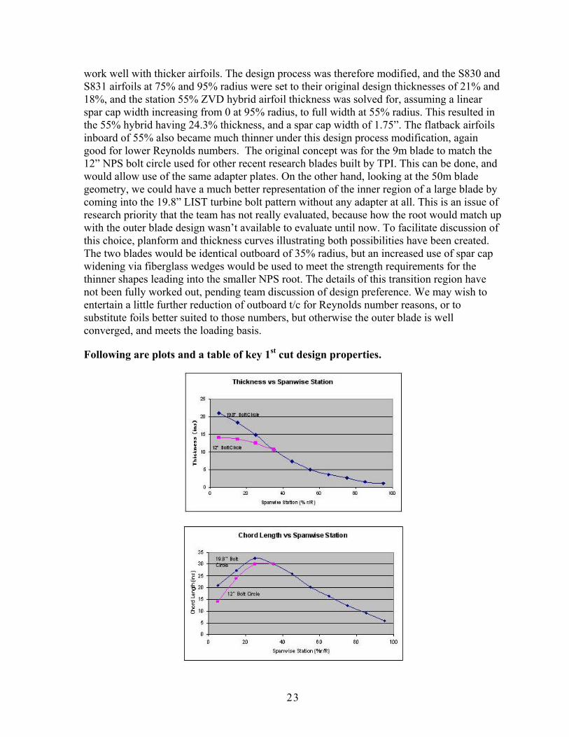
work well with thicker airfoils. The design process was therefore modified, and the S830 and S831 airfoils at 75% and 95% radius were set to their original design thicknesses of 21% and 18%, and the station 55% ZVD hybrid airfoil thickness was solved for, assuming a linear spar cap width increasing from 0 at 95% radius, to full width at 55% radius. This resulted in the 55% hybrid having 24.3% thickness, and a spar cap width of 1.75”. The flatback airfoils inboard of 55% also became much thinner under this design process modification, again good for lower Reynolds numbers. The original concept was for the 9m blade to match the 12” NPS bolt circle used for other recent research blades built by TPI. This can be done, and would allow use of the same adapter plates. On the other hand, looking at the 50m blade geometry, we could have a much better representation of the inner region of a large blade by coming into the 19.8” LIST turbine bolt pattern without any adapter at all. This is an issue of research priority that the team has not really evaluated, because how the root would match up with the outer blade design wasn’t available to evaluate until now. To facilitate discussion of this choice, planform and thickness curves illustrating both possibilities have been created. The two blades would be identical outboard of 35% radius, but an increased use of spar cap widening via fiberglass wedges would be used to meet the strength requirements for the thinner shapes leading into the smaller NPS root. The details of this transition region have not been fully worked out, pending team discussion of design preference. We may wish to entertain a little further reduction of outboard t/c for Reynolds number reasons, or to substitute foils better suited to those numbers, but otherwise the outer blade is well converged, and meets the loading basis.
Following are plots and a table of key 1st cut design properties.

24
After reviewing the design summary document presented above, the team weighed the merits and drawbacks of the design choices that were discussed. All agreed that somewhat thinner airfoils had to be employed on the 9 meter version of the blade due to the lower Reynolds Numbers during operation. Mike Zuteck worked with Case van Dam to develop airfoil geometries for regular spanwise intervals of the blade. The inboard portion of the blade utilized flatback airfoils, while the outboard section of the blade included high lift S830 and S831 airfoils. Because flatback airfoils are a nascent technology, the design team developed a standardized nomenclature to categorize the airfoils for this project. The generic series ‘FB-xxxx-yyyy’ was given to each airfoil. The FB at the beginning of the string refers to flatback airfoil. The ‘xxxx’ term refers to the thickness to chord ratio for the given airfoil and the ‘yyyy’ term refers to the trailing edge thickness to chord ratio. For example, an airfoil with the designation FB-4286-0802 is a flatback airfoil with a thickness to chord ratio of 0.4286 and a trailing edge thickness to chord ratio of 0.0802. Figure 8 shows the flatback airfoils developed for the inboard section of the blade, while Figure 9 and Figure 10 display the S830 and the S831 airfoils.
Figure 8 – Flatback Airfoil Sections for Inboard Section

25
Figure 9 – S830 Outboard Airfoil
Figure 10 – S831 Outboard Airfoil
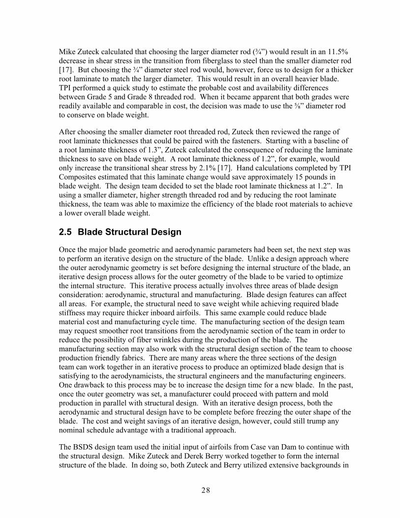
The other major design direction to be decided at this point was the root geometry. The team discussed the merits of changing the course of design for the 9 meter blade root. The starting design for the root was similar to the NPS-100 – 12 root fasteners on a bolt circle diameter of 300mm [15,16]. In order to better approximate a large (50 meter) blade design, the group felt it might make sense to enlarge the root diameter. This would better mimic the geometry of current multi-megawatt size blades. It would also allow for smaller, more numerous root fasteners – a practice also prevalent in large rotor blades. Finally, a larger root could match the current bolt pattern on the Micon test turbine at the USDA Bushland facility – thus allowing for a fit onto the turbine without the addition of an adapter plate. In consultation with Sandia, the group decided to make this change in the direction of the design. This required additional design details regarding the root fasteners. All previous 9 meter blades
26
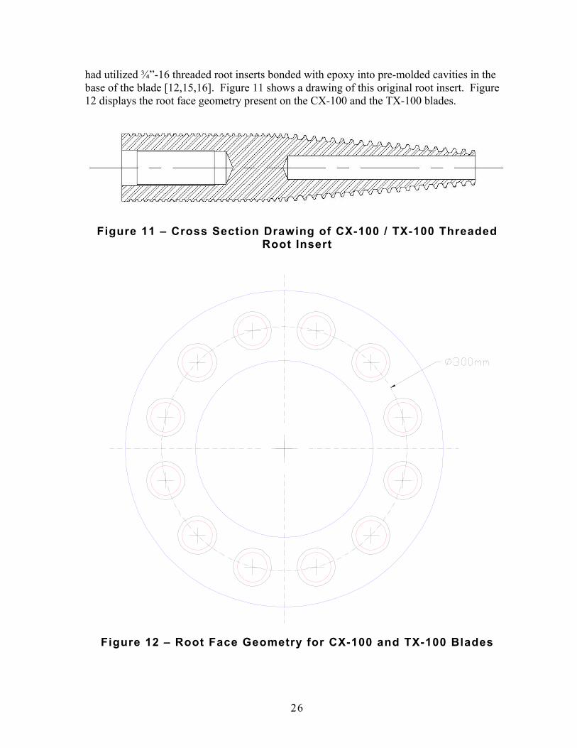
had utilized ¾”-16 threaded root inserts bonded with epoxy into pre-molded cavities in the base of the blade [12,15,16]. Figure 11 shows a drawing of this original root insert. Figure 12 displays the root face geometry present on the CX-100 and the TX-100 blades.
Figure 11 – Cross Section Drawing of CX-100 / TX-100 Threaded
Root Insert
Figure 12 – Root Face Geometry for CX-100 and TX-100 Blades

27
As mentioned above, in order to represent larger megawatt scale blades, the team decided to employ a greater number of smaller root fasteners. Mike Zuteck performed a design analysis on the required material, size and number of root fasteners required for the blade. Because the traditional threaded root inserts required a large amount of fiberglass root thickness, a decision was made to use imbedded threaded rod as the root fasteners. These threaded rods will slide into the holes on the hub of the test turbine – fastened on the rear side with washers and nuts. A cross section of a root fastener embedded in the blade is presented in Figure 13.
Figure 13 – Cross Section of Embedded Root Fastener
The number of root fasteners was set at 24 on a bolt circle diameter of 19.8” to match the hub of the Micon turbine [14]. In order to meet static and fatigue requirements for the blade root, the remainder of the design was a trade-off between threaded rod diameter and material strength. As shown in Figure 14, the nominal peak static stress on a ⅝” diameter steel rod would be about 21,068 psi, while a ¾” diameter rod would only register about 14,455 psi. Reviewing the endurance strengths of the various grades of steel, the team concluded that SAE Grade 5 steel would be fine for the ¾” diameter rod, while a ⅝” diameter rod would require the choice of SAE Grade 8 steel.
Figure 14 – Root Rod Nominal Stress and Endurance Strengths
28
Mike Zuteck calculated that choosing the larger diameter rod (¾”) would result in an 11.5% decrease in shear stress in the transition from fiberglass to steel than the smaller diameter rod [17]. But choosing the ¾” diameter steel rod would, however, force us to design for a thicker root laminate to match the larger diameter. This would result in an overall heavier blade. TPI performed a quick study to estimate the probable cost and availability differences between Grade 5 and Grade 8 threaded rod. When it became apparent that both grades were readily available and comparable in cost, the decision was made to use the ⅝” diameter rod to conserve on blade weight.
After choosing the smaller diameter root threaded rod, Zuteck then reviewed the range of root laminate thicknesses that could be paired with the fasteners. Starting with a baseline of a root laminate thickness of 1.3”, Zuteck calculated the consequence of reducing the laminate thickness to save on blade weight. A root laminate thickness of 1.2”, for example, would only increase the transitional shear stress by 2.1% [17]. Hand calculations completed by TPI Composites estimated that this laminate change would save approximately 15 pounds in blade weight. The design team decided to set the blade root laminate thickness at 1.2”. In using a smaller diameter, higher strength threaded rod and by reducing the root laminate thickness, the team was able to maximize the efficiency of the blade root materials to achieve a lower overall blade weight.
2.5 Blade Structural Design
Once the major blade geometric and aerodynamic parameters had been set, the next step was to perform an iterative design on the structure of the blade. Unlike a design approach where the outer aerodynamic geometry is set before designing the internal structure of the blade, an iterative design process allows for the outer geometry of the blade to be varied to optimize the internal structure. This iterative process actually involves three areas of blade design consideration: aerodynamic, structural and manufacturing. Blade design features can affect all areas. For example, the structural need to save weight while achieving required blade stiffness may require thicker inboard airfoils. This same example could reduce blade material cost and manufacturing cycle time. The manufacturing section of the design team may request smoother root transitions from the aerodynamic section of the team in order to reduce the possibility of fiber wrinkles during the production of the blade. The manufacturing section may also work with the structural design section of the team to choose production friendly fabrics. There are many areas where the three sections of the design team can work together in an iterative process to produce an optimized blade design that is satisfying to the aerodynamicists, the structural engineers and the manufacturing engineers. One drawback to this process may be to increase the design time for a new blade. In the past, once the outer geometry was set, a manufacturer could proceed with pattern and mold production in parallel with structural design. With an iterative design process, both the aerodynamic and structural design have to be complete before freezing the outer shape of the blade. The cost and weight savings of an iterative design, however, could still trump any nominal schedule advantage with a traditional approach.
The BSDS design team used the initial input of airfoils from Case van Dam to continue with the structural design. Mike Zuteck and Derek Berry worked together to form the internal structure of the blade. In doing so, both Zuteck and Berry utilized extensive backgrounds in

29
blade design and manufacturing to optimize the process. The team iterated on many occasions with Case van Dam to modify the airfoil sections as the design progressed.
Mike Zuteck produced blade airfoil section x-y coordinates at ten spanwise locations (measured in r/R): 15%, 20%, 25%, 35%, 45%, 55%, 65%, 75%, 85% and 95%. At the same time, Zuteck designed internal structural sections for each blade station. An example of an internal structural design for a blade station can be seen in Figure 15.
Figure 15 – Internal Structural Design – Blade Station 25% (r/R)
2.6 Blade Computer Model
At the same time, Derek Berry began to develop a three dimensional computer model of the outer geometry of the BSDS blade using the SolidWorks software program. In order to convert the airfoil coordinates into a blade model, the chart in Figure 16 was developed.
Figure 16 – Blade Model Geometry Details – Revision A

30
The overall radius of the turbine was set at 9 meters. With the existing hub radius on the Micon turbine, the blade length was calculated to be 8.325 meters. The root face of the blade occurred at an r/R of 7.5%. Using that information, all airfoil sections were then paired with a corresponding blade station. The chord length of each airfoil was determined using an AutoCAD drawing of the airfoil coordinates. This chord length, multiplied by a blade pitch axis location for each section, provided the actual center point of each airfoil for the three dimensional model. All ten sections were placed into a SolidWorks computer model using the proper x, y and z locations. Figure 17 shows a root end view of these airfoils in SolidWorks.
Figure 17 – Original Airfoil Sections – Root View
An initial lofting of the airfoil section, however, produced a less than desirable result – shown in Figures 18 and 19. The SolidWorks lofting routine assumes certain bounding conditions as it proceeds with the loft. For example, the program automatically chose where to bring the flatback section into the cylindrical root. Because the loft of the flatback panel converged into a very narrow arc of the root (about 15°), the resulting loft lines outboard became excessively wavy. In order to smooth the loft, the design team programmed the loft routine to enter the root at a larger arc (about 60°). As the team changed this and other design constraints, the resulting loft of the blade began to form the desired blade shape.

31
Figure 18 – First Pass Loft of BSDS Blade
Figure 19 – First Pass Loft of BSDS Blade

32
The design team completed many iterations to modify the blade geometry and the computer model to achieve the desired result. By tweaking the airfoil thickness, the flatback thickness ratio and the airfoil clocking position, the loft was improved significantly. Some of the intermediate results are presented in Figures 20 through 22.
Figure 20 – Intermediate Loft of BSDS Blade
Figure 21 – Intermediate Loft of BSDS Blade

33
Figure 22 – Intermediate Loft of BSDS Blade
After achieving satisfactory lofting results, blade twist was added to the three dimensional computer model. A new blade geometry table was created – adding twist for each blade section. This is shown in Figure 23.
Figure 23 – Blade Model Geometry Details – Twist Added

34
By rotating each blade section in the computer model, the blade airfoils were twisted to the indicated angle in the table above. Once all the sections were rotated, the model was lofted again. The results are displayed in Figure 24 and Figure 25.
Figure 24 – Twisted Airfoil Sections – Root View
Figure 25 – Blade Loft with Twisted Airfoil Sections

35
A total of 12 blade model iterations were performed in order to achieve the final blade geometry. During this process, the internal structural properties of the blade were continuously recalculated to ensure compliance with design. Also, a lot of thought was given to the eventual manufacturing process to be used to mold and assemble the blade. Checks were performed during the iterations at several blade locations to ensure smooth and even geometric contouring. An example of one of these checks is presented in Figures 26 through 29. A series of planes was used to cut the lofted surface. The planes were perpendicular to the chord at blade section 25% - and were located at 250mm, 300mm, 350mm, 400mm, 450mm and 500mm aft of the centerline. The planes cut through the flatback sections of the inboard airfoils. The resulting cuts in the lofted surface formed contour lines – like those on a map – that could be used to judge the change in elevation per unit transverse measurement.
Figure 26 – Check Planes for Flatback Geometry
Figure 27 – Check Planes for Flatback Geometry

36
Figure 28 – Lofted Surface Planar Cuts
Figure 29 – Flatback Section Contour Lines

37
The final version of the blade computer model included root cylinder thickness, root threaded rod and a blade tip. This version of the model is presented in Figures 30 through 34. It was at this point that the blade computer model was transferred to the TPI Tooling Department for pattern and mold production.
Figure 30 – Final BSDS Computer Model
Figure 31 – Final BSDS Computer Model

38
Figure 32 – Final BSDS Computer Model
Figure 33 – Final BSDS Computer Model

39
Figure 34 – Final BSDS Computer Model
2.7 Blade Buckling Analysis
After determining the blade’s internal structure and the outer geometry, Zuteck focused on confirming the stability of the blade under extreme loading. The area of the blade most susceptible to instability is the aft panel region of the low pressure skin at a spanwise location of maximum chord. The reason for this area’s heightened danger for buckling is because it is the largest area of unsupported panel on the compression skin (low pressure skin) of the blade. On the BSDS 9 meter blade, this area is centered on a spanwise location of 25% r/R. The key geometric parameters involved in buckling analysis include the core thickness, the skin thickness, the free-span dimensions of the panel, the radius of curvature and the panel aspect ratio [17]. Three buckling analysis methods were used to predict buckling in the specified location; the Peery method [18], the NACA TN 1928 method [19] and the SCI method [20]. The Peery method is the simplest, and computes a panel stiffness contribution and a panel curvature contribution. The method comes from Dave Peery, author of the book Aircraft Structures. The SCI method is based on work performed by Structural Composites, Inc., which did considerable work on composite wind turbine blades for NASA, including buckling predictions of composite blades. All of these methods were for uniform shell materials, with only the SCI method including oriented material effects [21]. All analyses were performed using conservative assumptions regarding panel fixity. Panels were assumed to be pinned at the shear webs, with no resistance to panel rotation at the attachment points [21].

40
The most stringent buckling result was returned by the Peery method with a buckling strain of 5,030 μs. The TN 1928 and the SCI methods returned values of 8,154 μs and 11,537 μs respectively [17]. Because the design limit strain for this area of the BSDS blade is 2,810 μs, the buckling margins for the three methods are, in order, 79%, 190% and 311%. The consensus of the three approaches verifies that the most obvious area susceptible to panel buckling on the BSDS blade has more than adequate margin at the design limit.
2.8 Blade Frequencies
The final analysis performed by Zuteck was a calculation of the blade’s first frequencies – both rotating and non-rotating. Figure 35 shows a table of the results.
Figure 35 – BSDS Blade First Frequencies
The relatively high blade frequencies are a result of thick airfoils, carbon spar caps and light weight blade skins [17].
2.9 Blade Laminate Schedule
Using the final blade geometry from the computer model, in conjunction with the final blade internal structural design, a laminate schedule was developed for the BSDS blade. Many of the materials used in the BSDS blade were also used to produce the CX-100 and TX-100 blades. A list of the materials included in the blade is presented in Figure 36.

41
Figure 36 – Material List for BSDS Blade
Using the materials above, laminates were developed for the high and low pressure skins, the flatback panel and the shear web. These laminates are presented in Figures 37 through 39.
Figure 37 – BSDS Skin Laminate Schedule

42
Figure 38 – BSDS Flatback Panel Laminate Schedule
Figure 39 – BSDS Shear Web Laminate Schedule

43
2.10 Blade Bill of Material
In preparation for the production of the BSDS blades, TPI constructed a Bill of Material (BOM). This aided TPI in purchasing material, planning labor, estimating material waste and managing the overall budget of the project. Using the material list and the laminate schedule presented in the previous section, TPI continued to develop a BOM with material infusion assumptions for each fabric and core material. An example of the fabric and matrix volume calculations is presented in Figure 40.
Figure 40 – Fiber Volume Calculations – 3/4oz Mat
Various blade specifications were also developed and organized to aid in the calculation of a BOM. A list of blade specifications related to the BSDS blade is shown in Figure 41.
Figure 41 – BSDS Blade Laminate and Assembly Specifications

44
Using the blade laminate schedule, the blade material list, the blade infusion assumptions and the blade specification list, a ply by ply property list was developed for the BSDS blade. The summation of the ply properties yields an overall blade part weight. The output material weights and volumes were used in the development of the final costs. Figure 42 shows the ply build up for the shear web.
Figure 42 – Ply Build Up for the BSDS Shear Web
A blade bonding analysis and a blade root insert analysis was completed to estimate the cost and weight of blade bonding materials and blade root hardware. These results are presented in Figure 43 and Figure 44.
Figure 43 – BSDS Blade Bonding Analysis
Figure 44 – BSDS Blade Root Hardware Analysis
Using all of the inputs above, a final BSDS blade bill of material was formulated. This BOM provided TPI with the costs associated with a production run of seven BSDS blades – including material scrap. This information was used to place a final order of manufacturing materials.

45
2.11 Blade Work Instructions
In preparation for a small production run of BSDS blades, shop floor work instructions were developed. As with the BOM, the initial set of work instructions was produced for the BSDS Detailed Design Review at Sandia. Both of these, however, are dynamic documents. By the time the seven BSDS blades were produced, the BOM had gone through three revisions, updating such items as base material costs, ply pattern areas, scrap percentages and bond gap tolerances. Likewise, the final set of BSDS shop floor work instructions were issued just prior to the production run. Each component of the BSDS blade assembly – HP skin, LP skin and shear web – had a set of work instructions. Figure 45 through Figure 48 show some examples of the work instructions.
Figure 45 – BSDS Skin Work Instruction
Figure 46 – BSDS Skin Work Instruction

46
Figure 47 – BSDS Skin Work Instruction
Figure 48 – BSDS Shear Web Work Instruction
47
3.0 BSDS Tooling
3.1 BSDS Plugs
After the Detailed Design Review, Sandia issued a “Go” for the remainder of the BSDS blade build project. At this point, TPI prepared to manufacture blade plugs, blade molds and blades assembly fixtures. In the past, TPI has relied on two-dimensional drawings to build blade plugs. For the first time, this project has given the company an opportunity to build a set of blade plugs from three-dimensional computer models. This enhances the accuracy of the project in many ways. Instead of hand lofting between sections on the shop floor, the geometry of any section can be cut and printed out from the computer model. Plug check templates were developed from the model and manufactured using a laser cutting process.
TPI tooling engineers used the BSDS three-dimensional computer model to create all of the necessary drawings for the HP plug, the LP plug and the shear web plug. A major design decision point was reached during the planning of BSDS plugs. The preliminary assumption going into the BSDS project was to have four molds (and thus four plugs) for the 9 meter flatback blade (HP skin, LP skin, flatback panel and shear web). However, TPI’s tooling department felt that two skin molds instead of three would present a simpler solution. The design group weighed the relative advantages and disadvantages of each approach (structural, manufacturing, similarity to 50 meter design, cost, etc.). TPI employee Roger McAlpine, who has had over 40 years of tooling experience, offered sound advice concerning the feasibility of each tooling scenario. After an in-depth discussion, the design group decided to produce a two piece mold for the BSDS blade.
After deciding on a two piece mold, the TPI prototype department was able to begin shaping the plug in that direction. One of the key decisions was where to place the split lines of the mold (and thus the blade). We decided to offset the split line on the leading edge onto the high pressure skin. We had done this with the ERS-100 (as well as the CX, TX and NPS) blade earlier [12,15,16]. The reasoning is to keep the split line – and thus any handwork (grinding) commonly associated with the manufacturing touch-up work on any seams – off of the critical nose of the airfoil. We had also decided with the ERS-100 that the high pressure skin was less sensitive to flow perturbation than the low pressure skin – thus the spit line was placed on the HP skin. TPI created a split line on the high pressure skin of the three-dimensional model. The placement of the split line was governed by two opposing conventions – locating the split far enough aft on the HP skin to ensure placement on a flat section of the airfoil while not progressing too far aft - which might endanger locking the infused skin in the mold. The team also had to be careful to create a smooth spanwise split line transition on the blade. The prototype department arrived at a solution that satisfied all of these conditions. The spit line was then added to the model and consequently the physical plug sections.
The TPI team also had to decide on a split line at the trailing edge. The three options included the joint between the HP skin and the flatback, the joint between the LP skin and the flatback or a joint created halfway down the flatback. Due to the possible difficulty of transitioning a split line from either joint (HP-flatback or LP-flatback) back to midpoint of

48
the root circle, we chose to create the split line halfway down the flatback surface. This allowed for a very even and smooth transition into the root split line.
After the decisions above were made, TPI embarked on the production of the plugs. A total of 22 two-dimensional airfoil sections were ‘cut’ from the surface model of the blade. These sections were offset for plug material thickness. Stringer notches were paced in predetermined locations. These sections were then sent out to be laser cut on half inch thick plywood. The completed sections were then set up on a strongback created on TPI’s shop floor for the purpose of constructing the BSDS plugs. Work then progressed on the surface of the BSDS 9 meter blade plug. The first plug to be worked on was the low pressure skin – the more difficult of the two skins. The LP skin includes the LE nose of the airfoil. Stringers and foam were added to the plywood airfoil sections. A layer of flexible (thin) plywood was then shaped over the top of the sections. The same process was followed for the HP plug. The final step of the process involved spraying a high-build surfacing gelcoat onto the outer surface of the plugs. This allowed the plugs to be polished in preparation for producing molds. Figure 49 through Figure 57 show the BSDS plugs in various stages of construction.
Figure 49 – BSDS Skin Plug

49
Figure 50 – BSDS Skin Plug
Figure 51 – BSDS Skin Plug

50
Figure 52 – BSDS Skin Plug
Figure 53 – BSDS Skin Plug

51
Figure 54 – BSDS Skin Plug
Figure 55 – BSDS Skin Plug

52
Figure 56 – BSDS Skin Plug
Figure 57 – BSDS Skin Plug

53
The team conducted discussions to decide the optimal method of producing a shear web plug and mold. The initial approach (tentatively decided upon during the start of the contract) was to form a shear web plug inside of the first set of blade skins. This would involve modifying a shear web produced out of the CX-100 or TX-100 web mold. The modified version of this web would then be used as a plug to create a new shear web mold for the BSDS blade. During the design phase of the BSDS blade, however, the team had several discussions concerning the merits and drawbacks of the existing shear web design. The current design has a web that is planar and flanges that twist to match blade angle. The result of this approach, however, is a shear web that is not perpendicular to the skins (spar caps) of the blade. (The web would be perpendicular in only one spanwise location.) The team agreed that a more sound approach would be to have the web twist in accordance with blade twist to always have the web perpendicular to the skins. In order to do this, however, TPI could not use the traditional approach of modifying a current shear web to produce a new shear web plug and mold. We would have to take a more extensive approach (in both cost and time) to produce a three-dimensional computer model of a twisted shear web and manufacture the shear web plug in a method very similar to the HP and LP skins discussed above. This would also introduce some uncertainty into the process – as it is not a direct fit method but one that is based on computer modeling including theoretical laminate and bond line thickness. Even with the additional risks, time and cost, however, we still felt this approach would result in a better blade design. Therefore, we proceeded to create a three-dimensional model of the shear web using the existing computer model of the outer blade skins. After completing the model, individual station sections were cut and assembled on a strong-back by the prototype department. Figure 58 and Figure 59 show the shear web plug in production.
Figure 58 – BSDS Twisted Shear Web Plug

54
Figure 59 – BSDS Twisted Shear Web Plug
3.2 BSDS Molds
The first step involved in manufacturing a composite mold is to build the cored fiberglass skin structure that becomes the female geometry of the mold surface. Once mold release had been applied to the high pressure and low pressure BSDS skin plugs, TPI’s prototype department sprayed tooling gelcoat onto the plug surface. This layer of gelcoat became the surface of the molds once the process was completed. After this first layer dried, the prototype department continued with the structural composite portion of the mold. Several layers of hand-lay-up glass as well as sprayed-chopped-fiber were applied to the entire surface. An intermediate layer of balsa core was added to provide stiffness. Finally, several more layers of chopped and hand-laid glass were added.
After building the fiberglass portion of the BSDS molds, the prototype department fabricated the steel bracing that becomes the legs and backbone of the molds. Square steel tubing (2”x2”) was welded together into a truss that mirrored the shape of the bottom of the skin molds. This steel truss was then suspended above the upside down molds (still in place on the plugs) using the shop crane. After the truss was positioned correctly, it was connected to the composite mold using fiberglass tabbing (hand-lay-up). The result of this is shown in Figure 60 through Figure 62.

55
Figure 60 – BSDS Skin Mold
Figure 61 – BSDS Skin Mold

56
Figure 62 – BSDS Skin Mold
Both BSDS skin molds were de-molded from the plugs and flipped onto their steel footing. At this point, the final details of mold finishing could be accomplished in preparation for blade molding. Both molds were cleaned and wiped down. The molds also required aluminum return flanges to be used during blade molding. These flanges bolted to the edges of the mold and provided a return flange to lay fabric under during manufacturing. These flanges had to be designed and produced to fit the exact contour of the skin molds. These flanges utilized embedded threaded inserts in the mold for fastening.
TPI also manufactured a shear web mold using the web plug discussed above. The same method was employed in producing this mold as was used for the skin molds. Figure 63 and Figure 64 show the shear web mold.

57
Figure 63 – BSDS Shear Web Mold
Figure 64 – BSDS Shear Web Mold

58
3.3 BSDS Root Stud Positioning Fixture
As mentioned earlier, the team decided to switch from threaded root inserts to threaded rod imbedded in the root of the BSDS blade. The assembly process no longer required a root stud insertion fixture. Instead, the ⅝” threaded rod had to be held in place at the root of the mold during laminate lay-up and infusion. In order to accomplish this, TPI designed and built a root stud positioning fixture. This fixture was attached to the root end of each of the skin molds during production of the blade. It held both the threaded rod inserts and blade root plates in place during manufacturing. Figure 65 through Figure 68 display the manufacturing drawings and assembly drawing for the fixture. Figure 69 and Figure 70 are pictures of the fixture during blade manufacturing.
Figure 65 – BSDS Root Stud Positioning Plate
Figure 66 – BSDS Root Stud Positioning Nut

59
Figure 67 – BSDS Root Stud Positioning Assembly
Figure 68 – BSDS Root Stud Positioning Assembly

60
Figure 69 – BSDS Root Stud Positioning Fixture
Figure 70 – BSDS Root Stud Positioning Fixture

61
3.4 BSDS Blade Assembly Fixture
TPI designed and manufactured a blade assembly fixture for the BSDS blades. The low pressure mold was used as the base for the assembly process. The shear web was bonded into place using jigs on the low pressure mold. The high pressure skin was secured into an assembly fixture with suction cups. Plates at the root end of the assemble fixture ensured that the BSDS bolt pattern was oriented correctly. Figure 71 shows a drawing of the root plates. Figure 72 shows a picture of the assembly fixture being constructed. Figure 73 and Figure 74 show the blade assembly fixture during production.
LP MOLD Figure 71 – BSDS Blade Assembly Fixture Drawing
Figure 72 – BSDS Blade Assembly Fixture

62
Figure 73 – BSDS Blade Assembly Fixture
Figure 74 – BSDS Blade Assembly Fixture

63
4.0 BSDS Blade Manufacturing
4.1 BSDS Root Threaded Inserts
The root fastening method of the BSDS blade was 24 ⅝”-18 threaded rods imbedded into the root laminate of the blade. The material of the threaded rod was SAE Grade 8 steel with rolled threads. The total length of the rod was 14”, including a 6” taper at the back end. The length of this taper was increased from 3” to 6” to decrease the load concentration on the outboard end of the threaded rod. Figure 75 shows a manufacturing drawing for the threaded rod.
Figure 75 – BSDS Root Threaded Rod
The threaded rod was imbedded into the fiberglass blade root by 9”. Another ½” was fastened into the BSDS root plate (discussed below). The remainder of the threaded rod extended outside of the root to be used to fasten the blade to the hub of the test turbine. Figure 76 displays a cross section of the assembly of the blade root and the turbine hub. Figure 77 shows threaded rods ready for insertion into the BSDS laminate.
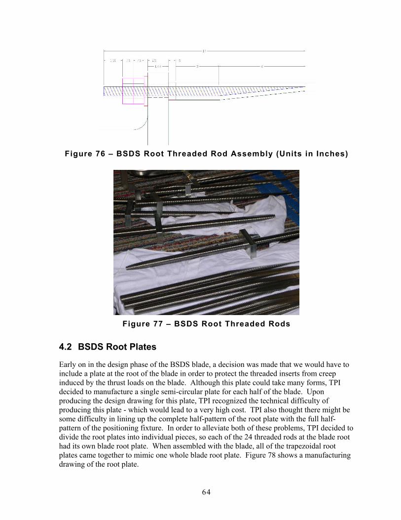
64
Figure 76 – BSDS Root Threaded Rod Assembly (Units in Inches)
Figure 77 – BSDS Root Threaded Rods
4.2 BSDS Root Plates
Early on in the design phase of the BSDS blade, a decision was made that we would have to include a plate at the root of the blade in order to protect the threaded inserts from creep induced by the thrust loads on the blade. Although this plate could take many forms, TPI decided to manufacture a single semi-circular plate for each half of the blade. Upon producing the design drawing for this plate, TPI recognized the technical difficulty of producing this plate - which would lead to a very high cost. TPI also thought there might be some difficulty in lining up the complete half-pattern of the root plate with the full half-pattern of the positioning fixture. In order to alleviate both of these problems, TPI decided to divide the root plates into individual pieces, so each of the 24 threaded rods at the blade root had its own blade root plate. When assembled with the blade, all of the trapezoidal root plates came together to mimic one whole blade root plate. Figure 78 shows a manufacturing drawing of the root plate.

65
Figure 78 – BSDS Root Plate Drawing
4.3 BSDS Pattern Cutting
Upon commencing manufacturing, the first step was to cut patterns for the entire production run. In the case of the BSDS, this included seven blades. The pattern shapes can be developed in two different ways. The first involves drawing patterns using a computer drafting program. If a three dimensional model of the blade is available, all of the material patterns can be extracted using the proper software. However, even with very accurate three dimensional representations of layer shapes, some hand trimming would have to be completed in the mold during ply insertion. Without the benefit of a three dimensional computer model of the blade, only some layers can be accurately drawn using a computer drafting program. Other layers have to be defined using paper patterns in the mold.
One of the critical laminate areas to be cut was the carbon spar cap. Each layer (there are seven layers of carbon spar cap per skin) was almost 9 meters long – but only 45mm wide. Furthermore, the layers tapered from this width down to a point at each end. These details ensured that cutting the spar cap layers would require great care. Even with these challenges, however, the cutting of the carbon went very well.
Other types of patterns were defined using the mold as a template. These patterns, such as the full skin layers, were detailed by laying paper in the three dimensional mold to define the

66
shape of the two dimensional pattern. Once the shape was defined, a more permanent template was produced using a material such as thin wood or cardboard. In order to cut these patterns using an automated cutting machine, these shapes would have to be digitized and turned into computer drawings. As mentioned above, the exception to this was the case where a three dimensional computer model is available – when all pattern shapes could be defined directly from computer data and thus cut on an automated machine without having to digitize hand patterns. The hand made patterns of the BSDS were not digitized because all patterns were cut by hand.
The final patterns created were for the balsa core in the aft and forward panels of the skin – as well as the flatback panel. These patterns, defined in the mold during the first lay-up of the skin, were then transferred to a more durable construction of thin wood. All of the material shapes were cut – 42 separate layers for each skin – and placed in order on a rolling manufacturing cart. These carts, called kits, were stationed next to the mold during the lay-up of the skins.
4.4 BSDS Material Lay-Up
After cutting the material patterns, the next step in the blade manufacturing process was to place the materials into the mold. All molds were prepared for demolding using a mold release agent. This step is known as Mold Prep. With newer, more efficient mold release agents, this application does not have to occur before each lay-up. The mold does, however, have to be cleaned before each lay-up.
The first layer to go down into the mold was the gelcoat. This became the outer layer of the blade, providing a clean finish to the blade as well as protecting the composite materials of the blade from the harmful effects of UV degradation. The gelcoat – colored white in the case of the BSDS – was sprayed onto the mold surface to a specified thickness. After the gelcoat was allowed to dry – or ‘tack’ – the rest of the laminate could then be placed into the mold.
After attaching the metal return flanges to the molds, skin layers number 2 through number 42 were placed into the molds utilizing the instructions of the floor laminate schedules. The layers included such materials as ¾ oz Mat, DBM-1708, DBM-1208, Carbon Triaxial, C260 and balsa core. Also included in the middle of the lay-up were the root threaded rods and fiberglass filler pieces (using scraps of C520 unidirectional fiberglass). Several of these layers are illustrated in Figures 79 through 89.
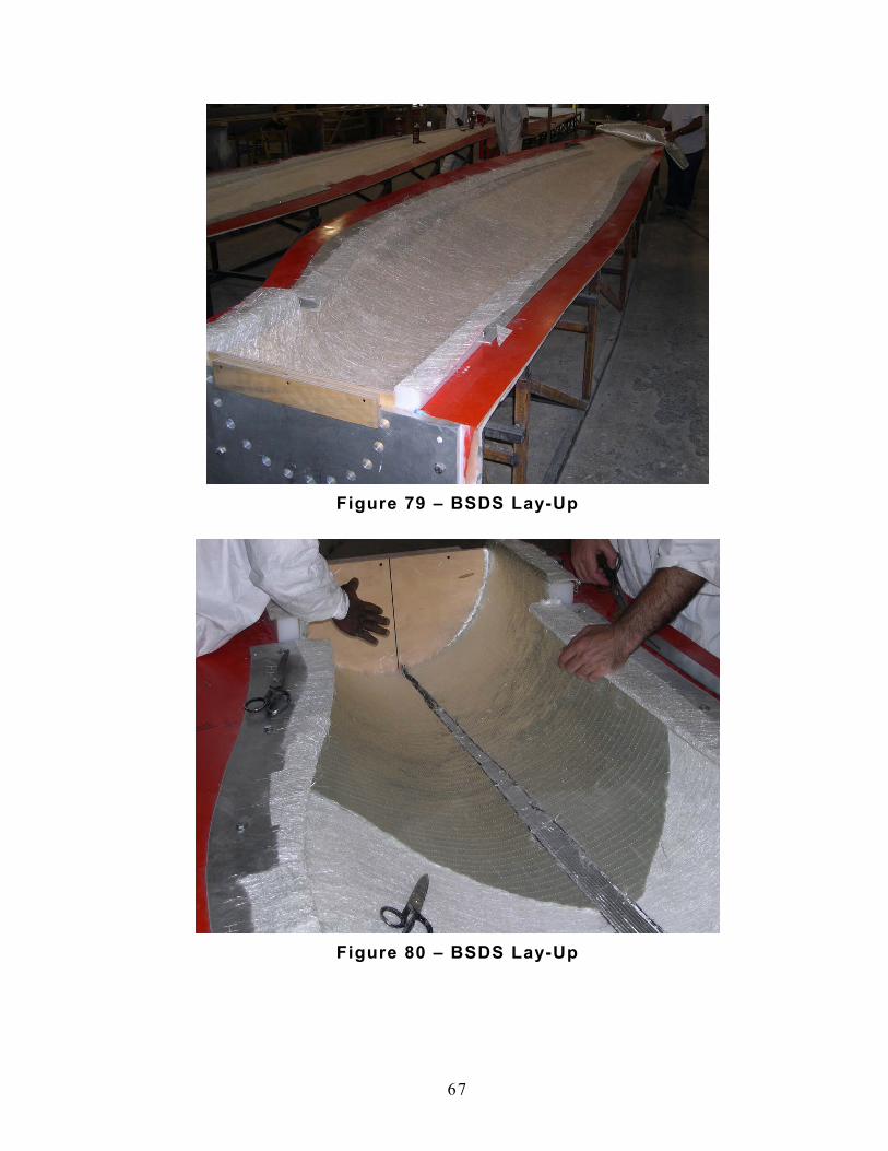
67
Figure 79 – BSDS Lay-Up
Figure 80 – BSDS Lay-Up

68
Figure 81 – BSDS Lay-Up
Figure 82 – BSDS Lay-Up
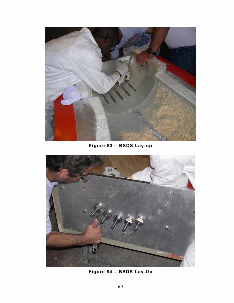
69
Figure 83 – BSDS Lay-up
Figure 84 – BSDS Lay-Up

70
Figure 85 – BSDS Lay-Up
Figure 86 – BSDS Lay-Up

71
Figure 87 – BSDS Lay-Up
Figure 88 – BSDS Lay-Up

72
Figure 89 – BSDS Lay-Up
4.5 BSDS Infusion
The manufacturing steps following material lay-up included vacuum bagging, infusion, post curing and demolding. The first step, vacuum bagging, occurred directly after all of the layers were placed into the mold. The blade was bagged using consumable materials. The main component was the nylon film vacuum bag. This covered the entire part and was sealed at the edges of the mold. Vacuum was pulled between the mold and the nylon bag, evacuating all air from the blade laminate. Also included in the process of vacuum bagging was placing all of the resin feed lines and the vacuum lines. These features, along with peel ply and infusion flow medium, augmented the infusion of epoxy into the dry blade laminate. Figures 90 through 91 demonstrate the process of vacuum bagging
Figure 90 – BSDS Vacuum Bagging
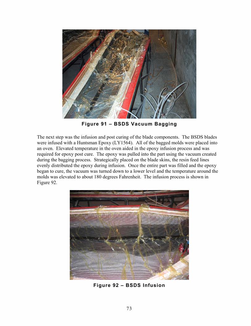
73
Figure 91 – BSDS Vacuum Bagging
The next step was the infusion and post curing of the blade components. The BSDS blades were infused with a Huntsman Epoxy (LY1564). All of the bagged molds were placed into an oven. Elevated temperature in the oven aided in the epoxy infusion process and was required for epoxy post cure. The epoxy was pulled into the part using the vacuum created during the bagging process. Strategically placed on the blade skins, the resin feed lines evenly distributed the epoxy during infusion. Once the entire part was filled and the epoxy began to cure, the vacuum was turned down to a lower level and the temperature around the molds was elevated to about 180 degrees Fahrenheit. The infusion process is shown in Figure 92.
Figure 92 – BSDS Infusion

74
4.6 BSDS Blade Assembly
After demolding the BSDS components – the low pressure skin, the high pressure skin and the shear web – the blade was assembled. The assembly of the BSDS blade included two major steps: web to LP skin and HP skin to web / LP skin.
Blade bonding occurred in the low pressure skin mold. After demolding and trimming, the LP skin was placed back into the LP mold and the HP skin was placed in the assembly fixture. The shear web was placed at the design location using computer generated templates. Using these templates as fixtures, the web was bonded into the LP skin with Plexus 550 adhesive. The blade assembly fixture placed the HP skin onto the top of the LP skin and web assembly. The high pressure skin was held in place in the assembly fixture using vacuum assisted suction cups. Once the lower shear web bond cured, the high pressure skin was bonded to the upper flange of the shear web and the leading and trailing edges of the low pressure skin using Plexus 550. This procedure was accomplished by applying adhesive to the surfaces of the low pressure skin and the shear web and then placing the high pressure skin onto the top of the assembly. The upper skin was held down with weights and straps – assuring a complete bond to the lower surfaces. The Plexus 550 was allowed to cure overnight while the blade was in the assembly fixture. Figure 93 through Figure 98 show the assembly process.
Figure 93 – BSDS Blade Assembly

75
Figure 94 – BSDS Blade Assembly
Figure 95 – BSDS Blade Assembly

76
Figure 96 – BSDS Blade Assembly
Figure 97 – BSDS Blade Assembly

77
Figure 98 – BSDS Blade Assembly
4.7 BSDS Blade Finishing
After completion of the assembly process, the blade proceeded to finishing. In this stage, the seams and edges were touched-up, gel coat was applied as necessary and the entire blade was buffed. Figure 99 through Figure 103 show the finishing process.
Figure 99 – BSDS Blade Finishing
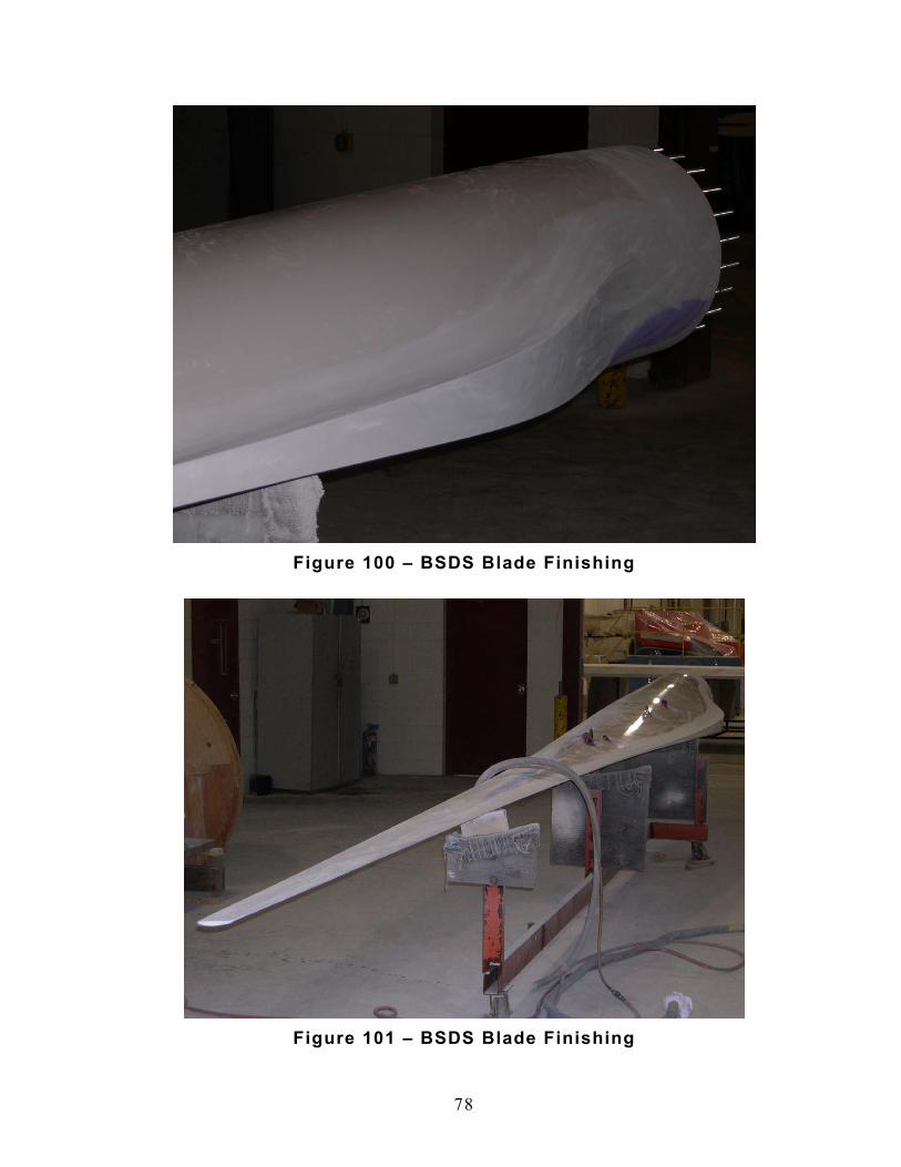
78
Figure 100 – BSDS Blade Finishing
Figure 101 – BSDS Blade Finishing

79
Figure 102 – BSDS Blade Finishing
Figure 103 – BSDS Blade Finishing

80
4.8 BSDS Instrumentation
During the assembly process, several of the BSDS blades were instrumented with strain gauges. A significant part of the BSDS project includes a flight test program to interrogate the performance of the blade. In an effort to support the test program and obtain useful data, TPI Composites and Sandia agreed to instrument four of the seven blades.
Blades #006 and #007 were fully instrumented with gages at approximately 75%, 50% and at 25% of span to measure flap wise bending strains. Additionally Blades #004, #005, #006 and #007 were instrumented with strain gages at the root to measure both flap wise and edge wise bending strains.
Figure 104 shows the full instrumentation applied to blades #006 and #007. Each pair of gages makes up a temperature-compensated half arm of a full bridge. Combining max and min bending strains (HP and LP skins) provides high bridge output for accurate strain measurement.
Figure 104 – BSDS Instrumentation Schematic
HP Skin LP Skin
Tra
ilin
g E
dge
Le
ad
ing
Ed
ge
Le
ad
ing
Ed
ge
Shear Web
Edgewise Root Moment F lapwise Root
Moment
15 mm
350 mm
2550
4500 mm
6750 mm
Wired as ful l bridge (see fig 4.31)
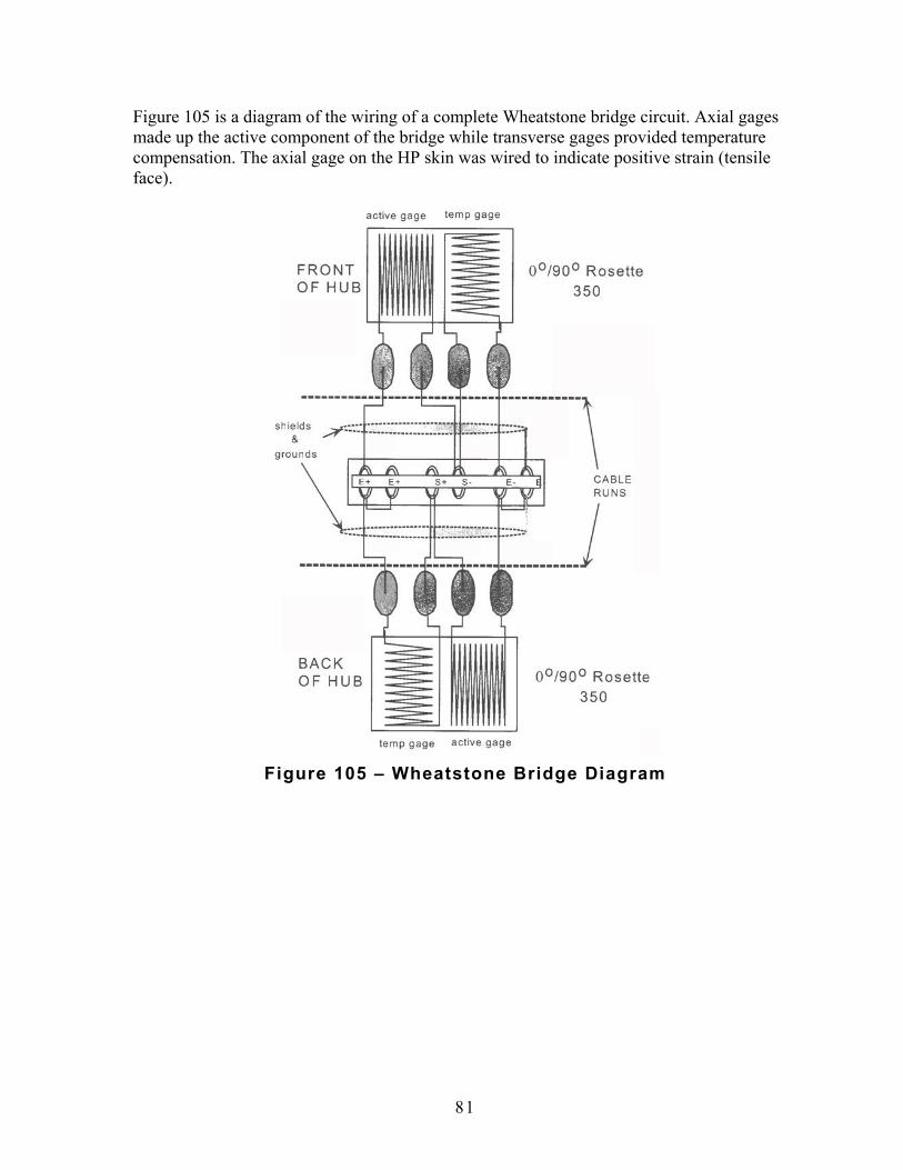
81
Figure 105 is a diagram of the wiring of a complete Wheatstone bridge circuit. Axial gages made up the active component of the bridge while transverse gages provided temperature compensation. The axial gage on the HP skin was wired to indicate positive strain (tensile face).
Figure 105 – Wheatstone Bridge Diagram

82
5.0 BSDS Blade Shipping Seven BSDS blades were manufactured at the TPI facility in Warren, Rhode Island. After production, each blade was weighed. Using the root and tip weights, the center of gravity of each blade was calculated. Figure 106 shows the configuration used to weigh each blade.
Figure 106 – BSDS Blade Weighing Configuration
The BSDS blade weights and centers of gravity were compiled into tables presented below. Figure 107 displays results in English units, while Figure 108 displays results in Metric units. Also included in each table are static balance, tip weight, blade notes and delivery location.
Figure 107 – BSDS Weight and CG Table (English Units)
Figure 108 – BSDS Weight and CG Table (Metric Units)

83
Finally, Figure 109 and Figure 110 show some of the preparations for shipping, including installation of plywood root covers and thread protection covers.
Figure 109 – BSDS Shipping Preparation
Figure 110 – BSDS Shipping Preparation

84
6.0 Conclusion The BSDS Phase II project successfully demonstrated the design and manufacturing of a full scale wind turbine blade using innovations developed during the first phase of the project. These innovations include flatback airfoils on inboard blade stations, a carbon fiber spar cap and an iterative blade design process.
Case van Dam led the development effort of the flatback airfoils used on the blade including the modeling and wind tunnel testing of the many airfoil variations. The inboard flatback shape proved to be very efficient structurally. The thick airfoils allowed for the reduction of material in the blade while still achieving the desired flapwise strength and stiffness. The flatback feature of the airfoils achieved the same results for the edgewise properties of the blade. Laboratory testing will determine the static strength, one fatigue data point and the modal properties of the BSDS blades. The blade field testing planned by Sandia will help to further determine the aerodynamic characteristics of the flatback airfoils. TPI Composites gained important experience in the manufacturing of flatback molds and blades. The benefit of the aerodynamic, structural and production knowledge of flatback airfoils acquired during this program will become more valuable as the technology is deployed on much larger turbine blades. An additional benefit may come with the reduced relative transportation costs associated with megawatt size flatback airfoil blades.
The BSDS project also continued to develop the design and manufacturing approach to using carbon in the spar cap of wind turbine blades. The spar caps were sized in conjunction with airfoil thickness to produce a constant thickness and constant width cap for more than 50% of the blade span. The outboard section of the spar cap continues with the same thickness, but includes a linear taper in width. This adds to the simplicity of the blade design and reduces the blade manufacturing part count and labor content. The BSDS blade design also focused on the material geometry required to bring a relatively thin carbon spar cap into a large fiberglass blade root. Using inboard spar cap width taper and off-axis fiberglass fabric, the spar cap structural loads are efficiently distributed to the blade root fastening system.
The BSDS blade team approached the design of the blade using an iterative process. Instead of a linear progression from aerodynamics to structures to manufacturing, the team gathered all design aspects into a circular flow to achieve an efficient design. For example, the structural engineers were able to reduce blade weight by working with the aerodynamicists to increase the thickness and flatback size of the airfoils. The manufacturing engineers also had an important role in designing for ease of production and robustness of process.
Although the 9 meter blade demonstrated the effectiveness of the innovations discussed above, greater benefits should be realized as these attributes are deployed on larger wind turbine blades. As the first phase of the BSDS project demonstrated, the intended target for these innovations are blades with a span of approximately 40 meters or longer. This project provides a solid foundation on which to build.
85
7.0 References
1. TPI Composites, "Parametric Study for Large Wind Turbine Blades," SAND2002-2519, Sandia National Laboratories, Albuquerque, NM, August 2002
2. TPI Composites, "Cost Study for Large Wind Turbine Blades," SAND2003-1428, Sandia National Laboratories, Albuquerque, NM, May 2003.
3. TPI Composites, "Innovative Design Approaches for Large Wind Turbine Blades," SAND2003-0723, Sandia National Laboratories, Albuquerque, NM, March 2003.
4. TPI Composites, "Innovative Design Approaches for Large Wind Turbine Blades–Final Report," SAND2004-0074, Sandia National Laboratories, Albuquerque, NM, May 2004.
5. Jackson, K., Zuteck, M., van Dam, C.P., Standish, K.J., and Berry, D., "Innovative Design Approaches for Large Wind Turbine Blades," Wind Energy, Vol. 8, No. 2, 2005, pp. 141-171.
6. Standish, K.J., and van Dam, C.P., "Aerodynamic Analysis of Blunt Trailing Edge Airfoils," Journal of Solar Energy Engineering, Vol. 125, No. 4, Nov. 2003, pp. 479-487.
7. Baker, J.P., van Dam, C.P., and Gilbert, B.L., "Flatback Airfoil Wind Tunnel Experiment," SAND2008-2008, Sandia National Laboratories, Albuquerque, NM, April 2008.
8. Chao, D.D., and van Dam, C.P., "CFD Analysis of Rotating Two-Bladed Flatback Wind Turbine Rotor," SAND2008-1688, Sandia National Laboratories, Albuquerque, NM., April 2008.
9. Simms, D., Schreck, S., Hand, M., and Fingersh, L.J., "NREL Unsteady Aerodynamics Experiment in the NASA-Ames Wind Tunnel: A Comparison of Predictions to Measurements," NREL/TP-500-29494, National Renewable Energy Laboratory, Golden, CO, June 2001.
10. Hand, M.M., Simms, D.A., Fingersh, L.J., Jager, D.W., Cotrell, J.R., Schreck, S.J., Larwood, S.M., "Unsteady Aerodynamics Experiment Phase VI: Wind Tunnel Test Configurations and Available Data Campaigns," NREL/TP-500-29955,National Renewable Energy Laboratory, Golden, CO, December 2001.
11. Giguère, P., and Selig, M.S., "Design of a Tapered and Twisted Blade for the NREL Combined Experiment Rotor," NREL/SR-500-26173, National Renewable Energy Laboratory, Golden, CO, April 1999.

86
12. TPI Composites, Inc. “Blade Manufacturing Improvements: Development of the ERS-100 Blade,” SAND2001-1381, Sandia National Laboratories, Albuquerque, NM, May 2001.
13. Griffin, D.A., Berry, D., Zuteck, M.D., and Ashwill, T.A. (January 2004). “Development of Prototype Carbon-Fiberglass Wind Turbine Blades: Conventional and Twist-Coupled Designs,” 2004 AIAA/ASME Wind Energy Symposium. Reno, NV.
14. Berry, D. Notes from BSDS Phase II contract kick-off meeting at Sandia National Laboratories on 24 August, 2004.
15. TPI Composites, "CX-100 Manufacturing Final Project Report," SAND2007-6065, Sandia National Laboratories, Albuquerque, NM, November 2007.
16. TPI Composites, "TX-100 Manufacturing Final Project Report," SAND2007-6066, Sandia National Laboratories, Albuquerque, NM, November 2007.
17. TPI Composites, “BSDS Phase II Design Review Package,” Presented at BSDS Phase II Design Review Meeting, February 2005, Sandia National Laboratories, Albuquerque, NM.
18. Peery, D. “Aircraft Structures,” McGraw Hill, 1950.
19. Bruhn, E.F., “Analysis and Design of Flight Vehicle Structures,” S.R. Jacobs, Indianapolis, IN, June 1973.
20. Wiengart, O. “Design, Evaluation and Fabrication of Low-Cost Composite Blades for Intermediate-Sized Wind Turbines,” Structural Composites Industries, Inc., September 1981.
21. Musial, W.D., Bourne, B, Hughes, S., and Zuteck, M.D. “Four-Point Bending Strength Testing of Pultruded Fiberglass Wind Turbine Blade Sections,” NREL/CP-500-30565, National Renewable Energy Laboratory, Golden, CO, September 2001.

87
DISTRIBUTION: Tom Acker Northern Arizona University PO Box 15600 Flagstaff, AZ 86011-5600 Ian Baring-Gould NREL/NWTC 1617 Cole Boulevard MS 3811 Golden, CO 80401 Keith Bennett U.S. Department of Energy Golden Field Office 1617 Cole Boulevard Golden, CO 80401-3393 Karl Bergey University of Oklahoma Aerospace Engineering Dept. Norman, OK 73069 Mike Bergey Bergey Wind Power Company 2200 Industrial Blvd. Norman, OK 73069 Derek Berry (10) TPI Composites, Inc. 373 Market Street Warren, RI 02885-0328 Gunjit Bir NREL/NWTC 1617 Cole Boulevard MS 3811 Golden, CO 80401 Marshall Buhl NREL/NWTC 1617 Cole Boulevard MS 3811 Golden, CO 80401
C.P. Sandy Butterfield NREL/NWTC 1617 Cole Boulevard MS 3811 Golden, CO 80401 Garrett Bywaters Northern Power Systems 182 Mad River Park Waitsfield, VT 05673 Doug Cairns Montana State University Dept. of Mechanical & Industrial Eng. College of Engineering PO Box 173800 Bozeman, MT 59717-3800 David Calley Southwest Windpower 1801 West Route 66 Flagstaff, AZ 86001 Larry Carr NASA Ames Research Center 24285 Summerhill Ave. Los Altos, CA 94024 Jamie Chapman Texas Tech University Wind Science & Eng. Research Center Box 41023 Lubbock, TX 79409-1023 Kip Cheney PO Box 456 Middlebury, CT 06762 Craig Christensen Clipper Windpower Technology, Inc. 6305 Carpinteria Ave. Suite 300 Carpinteria, CA 93013

88
R. Nolan Clark USDA - Agricultural Research Service PO Drawer 10 Bushland, TX 79012 C. Cohee Foam Matrix, Inc. 1123 E. Redondo Blvd. Inglewood, CA 90302 Joe Cohen Princeton Economic Research, Inc. 1700 Rockville Pike, Suite 550 Rockville, MD 20852 C. Jito Coleman Northern Power Systems 182 Mad River Park Waitsfield, VT 05673 Ken J. Deering The Wind Turbine Company PO Box 40569 Bellevue, WA 98015-4569 James Dehlsen Clipper Windpower Technology, Inc. 6305 Carpinteria Ave. Suite 300 Carpinteria, CA 93013 Edgar DeMeo Renewable Energy Consulting Services 2791 Emerson St. Palo Alto, CA 94306 S. Finn GE Global Research One Research Circle Niskayuna, NY 12309 Peter Finnegan GE Global Research One Research Circle Niskayuna, NY 12309
Trudy Forsyth NREL/NWTC 1617 Cole Boulevard Golden, CO 80401 Brian Glenn Clipper Windpower Technology, Inc. 6305 Carpinteria Ave. Suite 300 Carpinteria, CA 93013 R. Gopalakrishnan GE Wind Energy GTTC, 300 Garlington Road Greenville, SC 29602 Dayton Griffin Global Energy Concepts, LLC 1809 7th Ave., Suite 900 Seattle, WA 98101 Maureen Hand NREL/NWTC 1617 Cole Boulevard MS 3811 Golden, CO 80401 Thomas Hermann Odonata Research 202 Russell Ave. S. Minneapolis, MN 55405-1932 D. Hodges Georgia Institute of Technology 270 Ferst Drive Atlanta, GA 30332 William E. Holley GE Wind Energy GTTC, M/D 100D 300 Garlington Rd. PO Box 648 Greenville, SC 29602-0648 Adam Holman USDA - Agricultural Research Service PO Drawer 10 Bushland, TX 79012-0010

89
D.M. Hoyt NSE Composites 1101 N. Northlake Way, Suite 4 Seattle, WA 98103 Scott Hughes NREL/NWTC 1617 Cole Boulevard MS 3911 Golden, CO 80401 Kevin Jackson Dynamic Design 123 C Street Davis, CA 95616 Eric Jacobsen GE Wind Energy - GTTC 300 Garlington Rd. Greenville, SC 29602 George James Structures & Dynamics Branch Mail Code ES2 NASA Johnson Space Center 2101 NASA Rd 1 Houston, TX 77058 Jason Jonkman NREL/NWTC 1617 Cole Boulevard Golden, CO 80401 Gary Kanaby Knight & Carver Yacht Center 2423 Hoover Avenue National City, CA 91950 Benjamin Karlson EE2B/Forrestal Building Wind Energy Technology Department Room 5H-088 1000 Independence Ave. S.W. Washington, DC 20585
Jason Kiddy Aither Engineering, Inc. 4865 Walden Lane Lanham, MD 20706 M. Kramer Foam Matrix, Inc. PO Box 6394 Malibu, CA 90264 David Laino Windward Engineering 8219 Glen Arbor Dr. Rosedale, MD 21237-3379 Scott Larwood 1120 N. Stockton St. Stockton, CA 95203 Bill Leighty Alaska Applied Sciences, Inc. PO Box 20993 Juneau, AK 99802-0993 Wendy Lin GE Global Research One Research Circle Niskayuna, NY 12309 Steve Lockard TPI Composites, Inc. 373 Market Street Warren, RI 02885-0367 James Locke AIRBUS North America Eng., Inc. 213 Mead Street Wichita, KS 67202 James Lyons Novus Energy Partners 201 North Union St., Suite 350 Alexandria, VA 22314

90
David Malcolm Global Energy Concepts, LLC 1809 7th Ave., Suite 900 Seattle, WA 98101 John F. Mandell Montana State University 302 Cableigh Hall Bozeman, MT 59717 Tim McCoy Global Energy Concepts, LLC 1809 7th Ave., Suite 900 Seattle, WA 98101 L. McKittrick Montana State University Dept. of Mechanical & Industrial Eng. 220 Roberts Hall Bozeman, MT 59717 Amir Mikhail Clipper Windpower Technology, Inc. 6305 Carpinteria Ave. Suite 300 Carpinteria, CA 93013 Patrick Moriarty NREL/NWTC 1617 Cole Boulevard Golden, CO 80401 Walt Musial NREL/NWTC 1617 Cole Boulevard MS 3811 Golden, CO 80401 Library (5) NWTC NREL/NWTC 1617 Cole Boulevard Golden, CO 80401 Byron Neal USDA - Agricultural Research Service PO Drawer 10 Bushland, TX 79012
Steve Nolet TPI Composites, Inc. 373 Market Street Warren, RI 02885-0328 Richard Osgood NREL/NWTC 1617 Cole Boulevard Golden, CO 80401 Tim Olsen Tim Olsen Consulting 1428 S. Humboldt St. Denver, CO 80210 Robert Z. Poore Global Energy Concepts, LLC 1809 7th Ave., Suite 900 Seattle, WA 98101 Cecelia M. Poshedly (5) Office of Wind & Hydropower Techologies EE-2B Forrestal Building U.S. Department of Energy 1000 Independence Ave. SW Washington, DC 20585 Robert Preus Abundant Renewable Energy 22700 NE Mountain Top Road Newberg, OR 97132 Jim Richmond MDEC 3368 Mountain Trail Ave. Newberg Park, CA 91320 Michael Robinson NREL/NWTC 1617 Cole Boulevard Golden, CO 80401

91
Dan Sanchez U.S. Department of Energy NNSA/SSO PO Box 5400 MS 0184 Albuquerque, NM 87185-0184 Scott Schreck NREL/NWTC 1617 Cole Boulevard MS 3811 Golden, CO 80401 David Simms NREL/NWTC 1617 Cole Boulevard MS 3811 Golden, CO 80401 Brian Smith NREL/NWTC 1617 Cole Boulevard MS 3811 Golden, CO 80401 J. Sommer Molded Fieber Glass Companies/West 9400 Holly Road Adelanto, CA 92301 Ken Starcher Alternative Energy Institute West Texas A & M University PO Box 248 Canyon, TX 79016 Fred Stoll Webcore Technologies 8821 Washington Church Rd. Miamisburg, OH 45342 Herbert J. Sutherland HJS Consulting 1700 Camino Gusto NW Albuquerque, NM 87107-2615
Andrew Swift Texas Tech University Civil Engineering PO Box 41023 Lubbock, TX 79409-1023 J. Thompson ATK Composite Structures PO Box 160433 MS YC14 Clearfield, UT 84016-0433 Robert W. Thresher NREL/NWTC 1617 Cole Boulevard MS 3811 Golden, CO 80401 Steve Tsai Stanford University Aeronautics & Astronautics Durand Bldg. Room 381 Stanford, CA 94305-4035 William A. Vachon W. A. Vachon & Associates PO Box 149 Manchester, MA 01944 C.P. van Dam Dept. of Mechanical & Aerospace Eng. University of California, Davis One Shields Avenue Davis, CA 95616-5294 Jeroen van Dam Windward Engineering NREL/NWTC 1617 Cole Boulevard Golden, CO 80401 Brian Vick USDA - Agricultural Research Service PO Drawer 10 Bushland, TX 79012

92
Carl Weinberg Weinberg & Associates 42 Green Oaks Court Walnut Creek, CA 94596-5808 Kyle Wetzel Wetzel Engineering, Inc. PO Box 4153 Lawrence, KS 66046-1153 Mike Zuteck MDZ Consulting 601 Clear Lake Road Clear Lake Shores, TX 77565 INTERNAL DISTRIBUTION: MS 0557 D.T. Griffith, 1524 MS1124 J.R. Zayas, 6333 MS 1124 T.D. Ashwill, 6333 MS 1124 M.F. Barone, 6333 MS 1124 D.E. Berg, 6333 (10) MS 1124 S.M. Gershin, 6333 MS 1124 R.R. Hill, 6333 MS 1124 W. Johnson, 6333 MS 1124 D.L. Laird, 6333 MS 1124 D.W. Lobitz, 6333 MS 1124 J. Paquette, 6333 MS 1124 M.A. Rumsey, 6333 MS 1124 J. Stinebaugh, 6333 MS 1124 P.S. Veers, 6333 MS 0899 Technical Library, 9536 (Electronic)
