blast-it-all pressure blast cabinet
TRANSCRIPT
BLAST-IT-ALL® PRESSURE BLAST CABINET
NOTE: It is the responsibility of the user to read and understand this manual and to provide a safe workenvironment for any operator. No representation is intended as to the suitability of this equipment for anyspecific application. Media selection and production rates are the sole responsibility of the end user. Theuser takes full responsibility to insure compliance with regulations and safe operation on this equipment.
WARNINGDO NOT USE SAND. SAND WILL CAUSE SILICA DUST, WHICH IS THE CAUSEOF SILICOSIS DISEASE, A CONDITION OF MASSIVE FIBROSIS OF THE LUNGS. THISSTATEMENT INDICATES POTENTIAL PERSONNEL HAZARD.
FAILURE TO COMPLY WITH THESE INSTRUCTIONSMAY RESULT IN PERSONAL INJURY.
WEBSITE CONCERNING SILICOSIS:http://www.osha.gov/Silica/IT69D_1.html
MANUAL NUMBER: 669 DATE OF ISSUE: AUGUST 2009
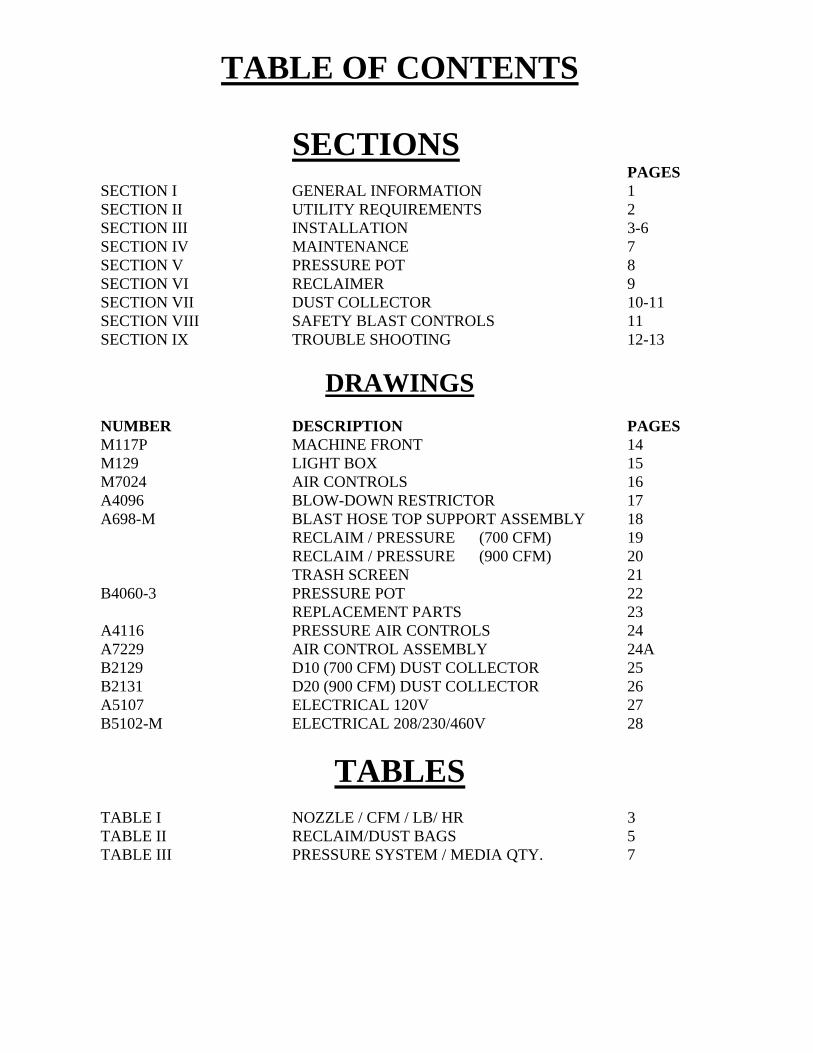
TABLE OF CONTENTS
SECTIONS
PAGES SECTION I GENERAL INFORMATION 1 SECTION II UTILITY REQUIREMENTS 2 SECTION III INSTALLATION 3-6 SECTION IV MAINTENANCE 7 SECTION V PRESSURE POT 8 SECTION VI RECLAIMER 9 SECTION VII DUST COLLECTOR 10-11 SECTION VIII SAFETY BLAST CONTROLS 11 SECTION IX TROUBLE SHOOTING 12-13
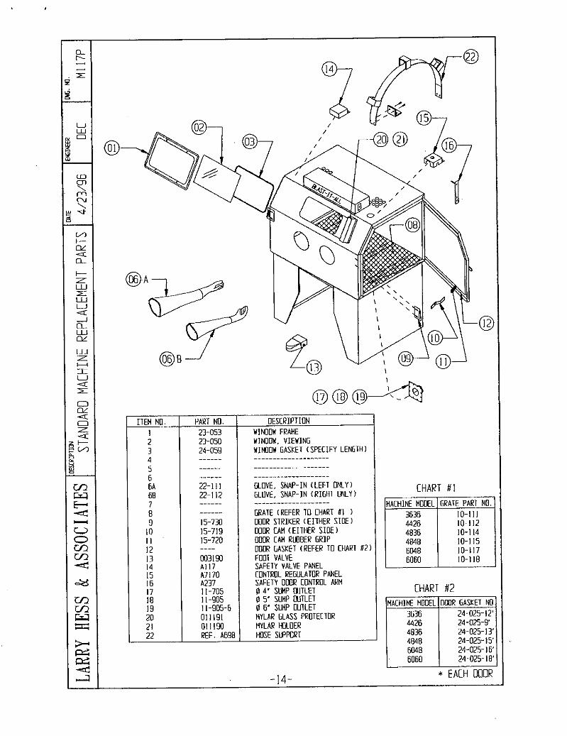
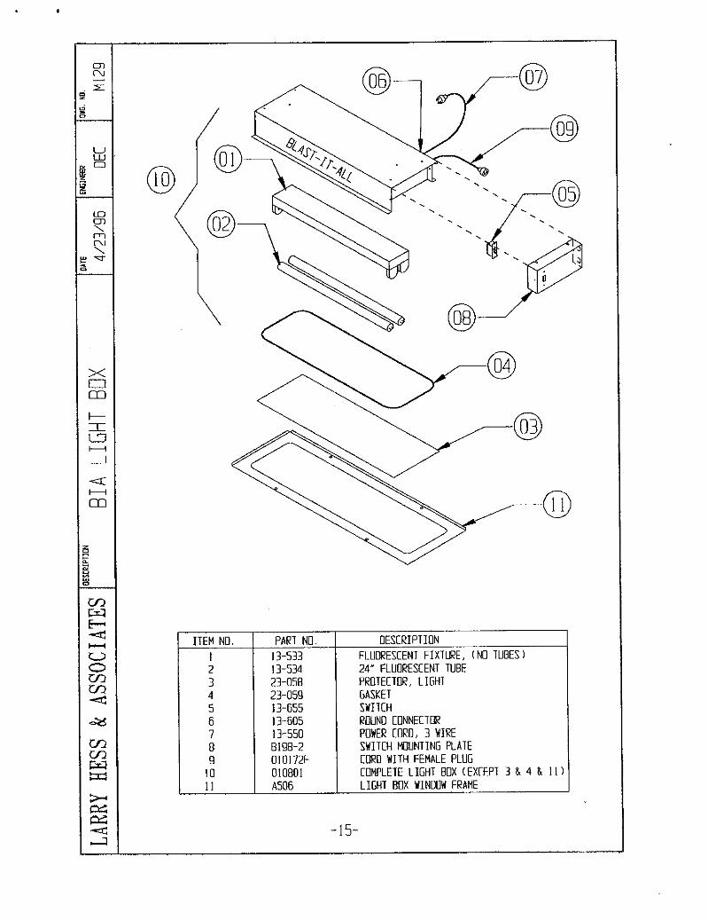
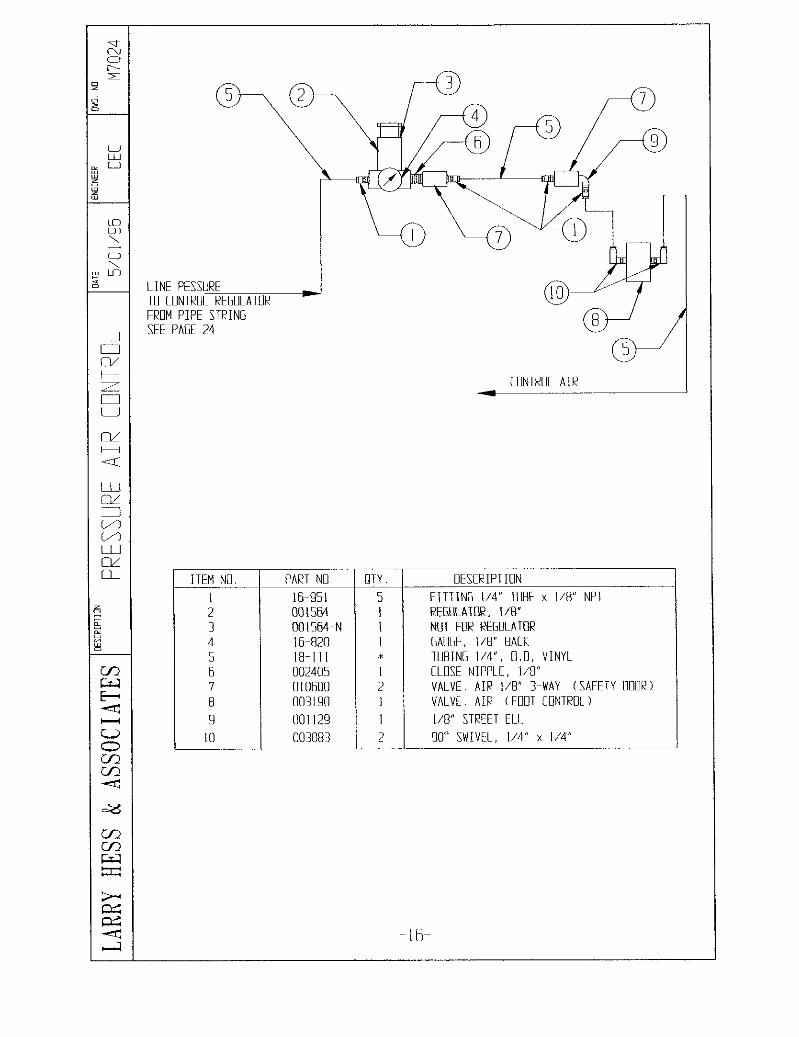
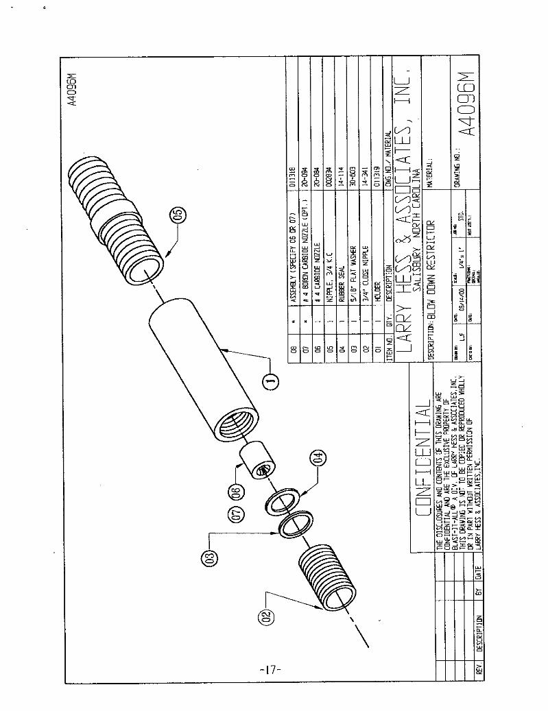
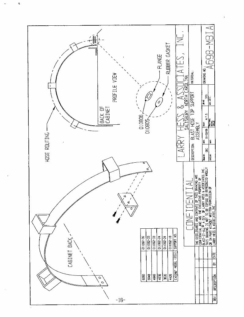
DRAWINGS NUMBER DESCRIPTION PAGES M117P MACHINE FRONT 14 M129 LIGHT BOX 15 M7024 AIR CONTROLS 16 A4096 BLOW-DOWN RESTRICTOR 17 A698-M BLAST HOSE TOP SUPPORT ASSEMBLY 18 RECLAIM / PRESSURE (700 CFM) 19 RECLAIM / PRESSURE (900 CFM) 20 TRASH SCREEN 21 B4060-3 PRESSURE POT 22
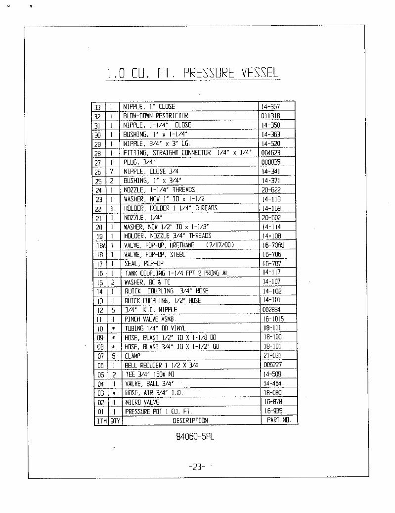
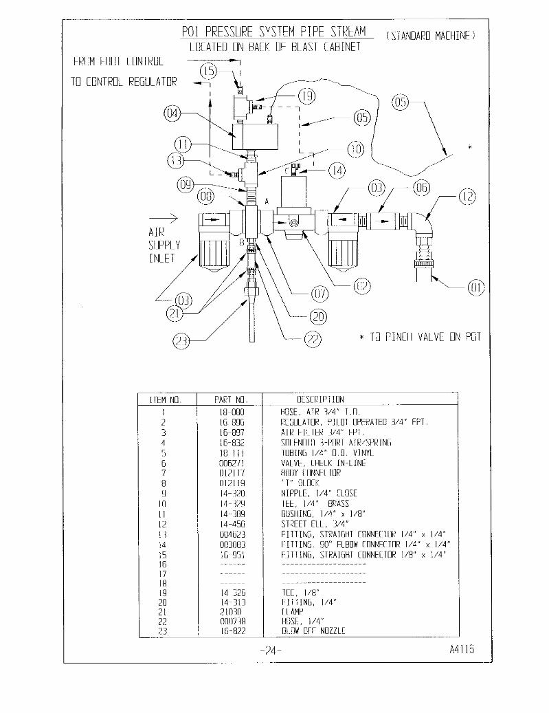
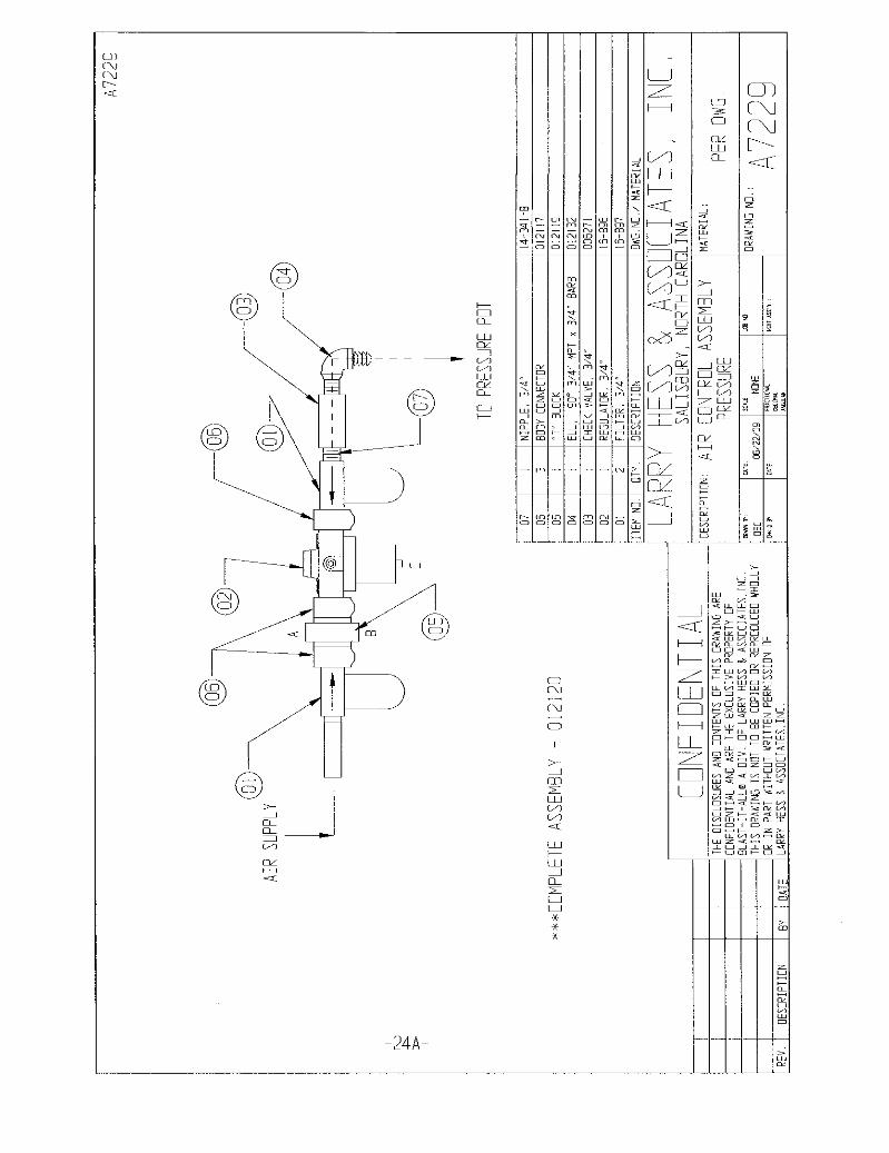
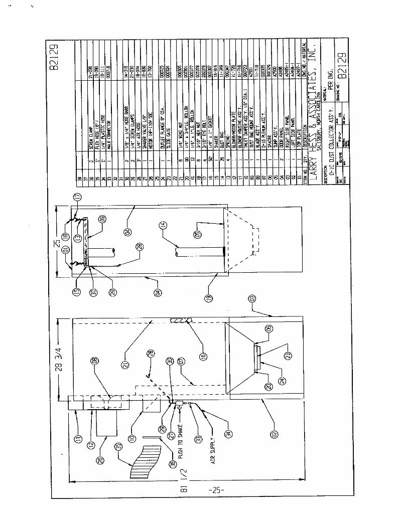
REPLACEMENT PARTS 23 A4116 PRESSURE AIR CONTROLS 24 A7229 AIR CONTROL ASSEMBLY 24A B2129 D10 (700 CFM) DUST COLLECTOR 25 B2131 D20 (900 CFM) DUST COLLECTOR 26 A5107 ELECTRICAL 120V 27 B5102-M ELECTRICAL 208/230/460V 28
TABLES TABLE I NOZZLE / CFM / LB/ HR 3
TABLE II RECLAIM/DUST BAGS 5 TABLE III PRESSURE SYSTEM / MEDIA QTY. 7
SECTION I DESCRIPTION AND GENERAL INFORMATION 1-1 Purpose and Scope
This publication contains operations and maintenance instructions with a trouble shooting guide and illustrated parts breakdown for the Larry Hess & Associates, Inc. Dry Blast Cabinet.
1-2 The blast cleaning machine is of the enclosed type. Parts for processing are loaded into
the cabinet through doors on the right or left side of the cabinet. The operator’s hands are inserted into a pair of gloves to protect the operator and to retain the media in the enclosure. Observation of parts in process is through a tempered glass window in the cabinet front. The unit also contains a sealed, two tube, fluorescent light which illuminates the work area. Machines are equipped with a safety interlocks which control the blasting process and provides a measure of safety for the blast operator.
An externally supplied compressed air pressure propels the media for abrasive blasting cleaning. The air pressure is routed through a moisture separator, pressure regulator, and blast control to the nozzle.
The blast cleaning machine is equipped with a media reclaiming cyclone separator. Media, dust, and debris are returned from the cabinet sump for separation. Reusable material drops through a filter screen where large particles are trapped, and into the storage hopper for reuse. The cyclone separator is equipped with an adjustable slide tube assembly, which controls the amount of dust being removed from the media.
Air and dust exhausted from the cyclone separator may be contained by several means. Standard means is the use of a Dust Bag attached to the outlet of the blower. OPTIONAL Dust collector systems are offered and easily installed with the machine.
1-3 General Information
This machine is designed primarily for blast cleaning with glass beads, (size 3-13) or aluminum oxide (size 46-220). Other types and sizes of blast media require special consideration. The nozzle pressure and media is determined by the application.
PAGE 1
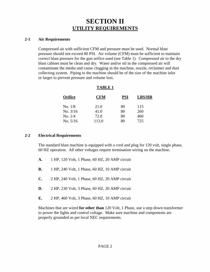
SECTION II UTILITY REQUIREMENTS 2-1 Air Requirements
Compressed air with sufficient CFM and pressure must be used. Normal blast pressure should not exceed 80 PSI. Air volume (CFM) must be sufficient to maintain correct blast pressure for the gun orifice used (see Table 1). Compressed air to the dry blast cabinet must be clean and dry. Water and/or oil in the compressed air will contaminate the media and cause clogging in the machine, nozzle, reclaimer and dust collecting system. Piping to the machine should be of the size of the machine inlet or larger to prevent pressure and volume loss. TABLE 1
Orifice CFM PSI LBS/HR
No. 1/8 21.0 80 115 No. 3/16 41.0 80 260 No. 1/4 72.0 80 460 No. 5/16 113.0 80 725
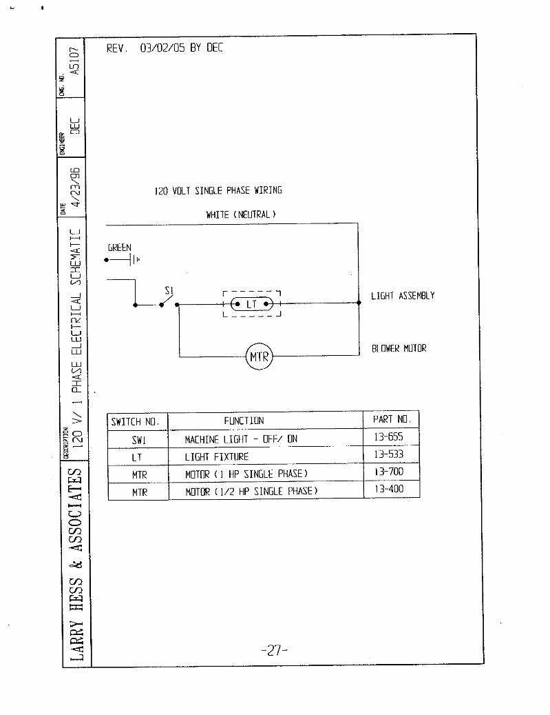
2-2 Electrical Requirements
The standard blast machine is equipped with a cord and plug for 120 volt, single phase, 60 HZ operation. All other voltages require termination wiring on the machine.
A. 1 HP, 120 Volt, 1 Phase, 60 HZ, 20 AMP circuit
B. 1 HP, 240 Volt, 1 Phase, 60 HZ, 10 AMP circuit
C. 2 HP, 240 Volt, 1 Phase, 60 HZ, 20 AMP circuit
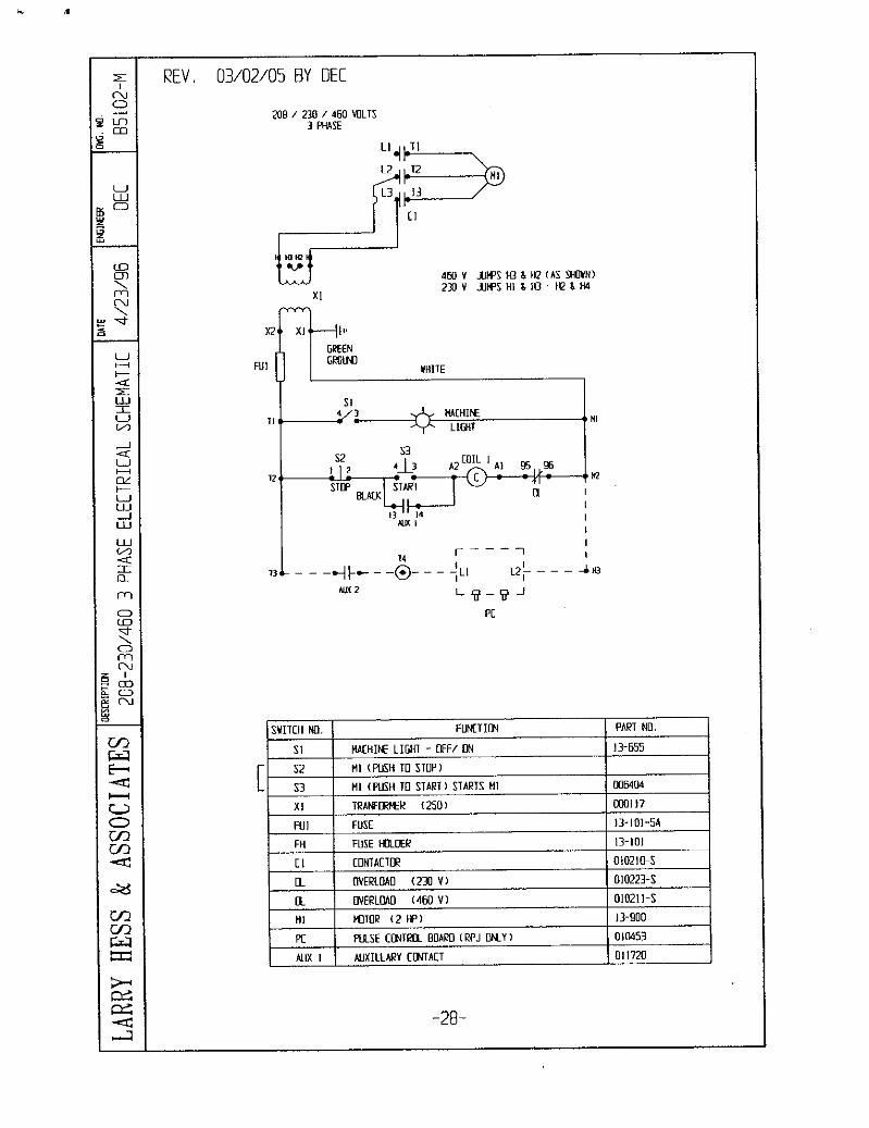
D. 2 HP, 230 Volt, 3 Phase, 60 HZ, 20 AMP circuit
E. 2 HP, 460 Volt, 3 Phase, 60 HZ, 10 AMP circuit
Machines that are wired for other than 120 Volt, 1 Phase, use a step down transformer to power the lights and control voltage. Make sure machine and components are properly grounded as per local NEC requirements.
PAGE 2
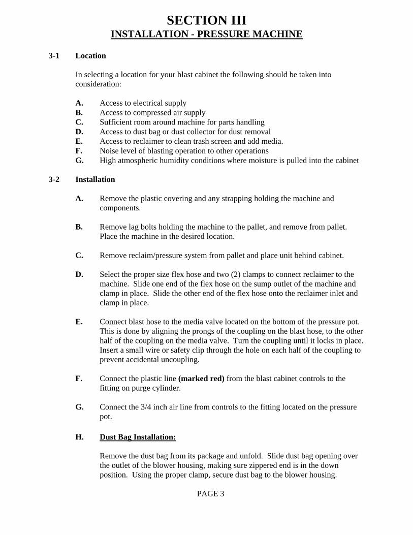
SECTION III INSTALLATION - PRESSURE MACHINE 3-1 Location
In selecting a location for your blast cabinet the following should be taken into consideration:
A. Access to electrical supply B. Access to compressed air supply C. Sufficient room around machine for parts handling D. Access to dust bag or dust collector for dust removal E. Access to reclaimer to clean trash screen and add media. F. Noise level of blasting operation to other operations G. High atmospheric humidity conditions where moisture is pulled into the cabinet
3-2 Installation
A. Remove the plastic covering and any strapping holding the machine and components.
B. Remove lag bolts holding the machine to the pallet, and remove from pallet. Place the machine in the desired location.
C. Remove reclaim/pressure system from pallet and place unit behind cabinet.
D. Select the proper size flex hose and two (2) clamps to connect reclaimer to the
machine. Slide one end of the flex hose on the sump outlet of the machine and clamp in place. Slide the other end of the flex hose onto the reclaimer inlet and clamp in place.
E. Connect blast hose to the media valve located on the bottom of the pressure pot. This is done by aligning the prongs of the coupling on the blast hose, to the other half of the coupling on the media valve. Turn the coupling until it locks in place. Insert a small wire or safety clip through the hole on each half of the coupling to prevent accidental uncoupling.
F. Connect the plastic line (marked red) from the blast cabinet controls to the
fitting on purge cylinder.
G. Connect the 3/4 inch air line from controls to the fitting located on the pressure pot.
H. Dust Bag Installation:
Remove the dust bag from its package and unfold. Slide dust bag opening over
the outlet of the blower housing, making sure zippered end is in the down position. Using the proper clamp, secure dust bag to the blower housing.
PAGE 3
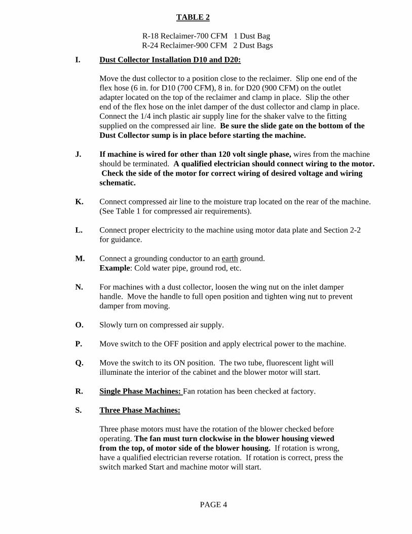
TABLE 2
R-18 Reclaimer-700 CFM 1 Dust Bag R-24 Reclaimer-900 CFM 2 Dust Bags
I. Dust Collector Installation D10 and D20:
Move the dust collector to a position close to the reclaimer. Slip one end of the flex hose (6 in. for D10 (700 CFM), 8 in. for D20 (900 CFM) on the outlet adapter located on the top of the reclaimer and clamp in place. Slip the other end of the flex hose on the inlet damper of the dust collector and clamp in place. Connect the 1/4 inch plastic air supply line for the shaker valve to the fitting supplied on the compressed air line. Be sure the slide gate on the bottom of the Dust Collector sump is in place before starting the machine.
J. If machine is wired for other than 120 volt single phase, wires from the machine should be terminated. A qualified electrician should connect wiring to the motor. Check the side of the motor for correct wiring of desired voltage and wiring schematic.
K. Connect compressed air line to the moisture trap located on the rear of the machine.
(See Table 1 for compressed air requirements).
L. Connect proper electricity to the machine using motor data plate and Section 2-2 for guidance.
M. Connect a grounding conductor to an earth ground. Example: Cold water pipe, ground rod, etc.
N. For machines with a dust collector, loosen the wing nut on the inlet damper
handle. Move the handle to full open position and tighten wing nut to prevent damper from moving.
O. Slowly turn on compressed air supply. P. Move switch to the OFF position and apply electrical power to the machine.
Q. Move the switch to its ON position. The two tube, fluorescent light will illuminate the interior of the cabinet and the blower motor will start.
R. Single Phase Machines: Fan rotation has been checked at factory.
S. Three Phase Machines:
Three phase motors must have the rotation of the blower checked before
operating. The fan must turn clockwise in the blower housing viewed from the top, of motor side of the blower housing. If rotation is wrong, have a qualified electrician reverse rotation. If rotation is correct, press the switch marked Start and machine motor will start.
PAGE 4
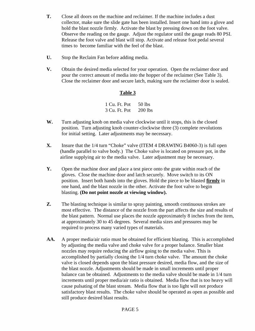
T. Close all doors on the machine and reclaimer. If the machine includes a dust
collector, make sure the slide gate has been installed. Insert one hand into a glove and hold the blast nozzle firmly. Activate the blast by pressing down on the foot valve. Observe the reading on the gauge. Adjust the regulator until the gauge reads 80 PSI. Release the foot valve and blast will stop. Activate and release foot pedal several times to become familiar with the feel of the blast.
U. Stop the Reclaim Fan before adding media.
V. Obtain the desired media selected for your operation. Open the reclaimer door and
pour the correct amount of media into the hopper of the reclaimer (See Table 3). Close the reclaimer door and secure latch, making sure the reclaimer door is sealed.
Table 3
1 Cu. Ft. Pot 50 lbs
3 Cu. Ft. Pot 200 lbs
W. Turn adjusting knob on media valve clockwise until it stops, this is the closed position. Turn adjusting knob counter-clockwise three (3) complete revolutions for initial setting. Later adjustments may be necessary.
X. Insure that the 1/4 turn “Choke” valve (ITEM 4 DRAWING B4060-3) is full open (handle parallel to valve body.) The Choke valve is located on pressure pot, in the airline supplying air to the media valve. Later adjustment may be necessary.
Y. Open the machine door and place a test piece onto the grate within reach of the
gloves. Close the machine door and latch securely. Move switch to its ON position. Insert both hands into the gloves. Hold the piece to be blasted firmly in
one hand, and the blast nozzle in the other. Activate the foot valve to begin blasting. (Do not point nozzle at viewing window).
Z. The blasting technique is similar to spray painting, smooth continuous strokes are most effective. The distance of the nozzle from the part affects the size and results of the blast pattern. Normal use places the nozzle approximately 8 inches from the item, at approximately 30 to 45 degrees. Several media sizes and pressures may be required to process many varied types of materials.
AA. A proper media/air ratio must be obtained for efficient blasting. This is accomplished
by adjusting the media valve and choke valve for a proper balance. Smaller blast nozzles may require reducing the airflow going to the media valve. This is accomplished by partially closing the 1/4 turn choke valve. The amount the choke valve is closed depends upon the blast pressure desired, media flow, and the size of the blast nozzle. Adjustments should be made in small increments until proper balance can be obtained. Adjustments to the media valve should be made in 1/4 turn increments until proper media/air ratio is obtained. Media flow that is too heavy will cause pulsating of the blast stream. Media flow that is too light will not produce satisfactory blast results. The choke valve should be operated as open as possible and still produce desired blast results.
PAGE 5
CC. Dust Removal - Dust Bags:
Obtain a container and place under the dust bag. Use the zipper in the bottom of
the dust bag to open the bag and allow the accumulated dust to flow into the container. When the dust has been transferred into the container, close the dust bag by moving the zipper to its closed position. CAUTION: Never open Dust Bag with Motor Running!
DD. Dust Removal - Dust Collector:
With motor off, press the button of the air operated vibrator valve mounted on the side of the dust collector. When vibrator is activated, you will be able to hear the vibrator shaking the bags inside the dust collector. The vibrator should be activated for one (1) minute before releasing. Obtain a container and place under the slide gate on the sump of the dust collector. Slowly move slide gate to its OPEN position and the accumulated dust will flow into the container. When dust has stopped flowing, close the slide gate.
CAUTION: NEVER ACTIVATE SHAKER OR SLIDE GATE WITH MOTOR RUNNING
Note:Dust removed from the dust bag or dust collector must be disposed of in an approved manner. This dust is WASTE and should NEVER BE PUT BACK INTO THE MACHINE.
PAGE 6
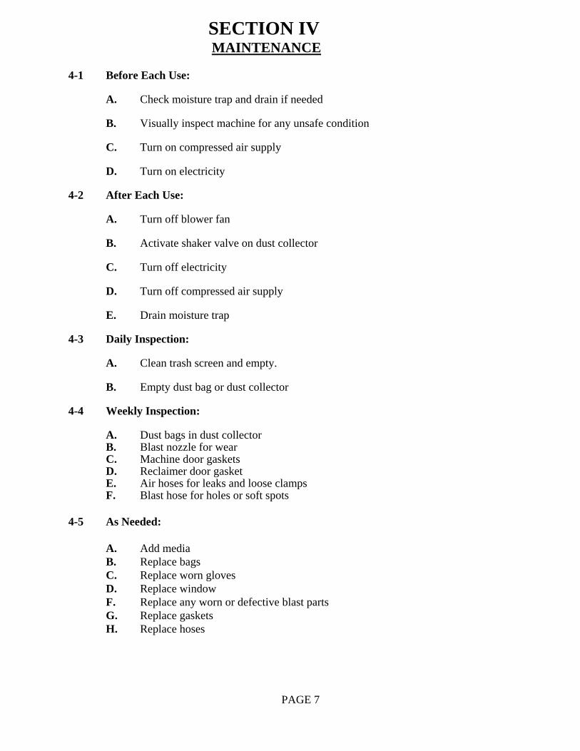
SECTION IV MAINTENANCE 4-1 Before Each Use:
A. Check moisture trap and drain if needed
B. Visually inspect machine for any unsafe condition
C. Turn on compressed air supply
D. Turn on electricity 4-2 After Each Use:
A. Turn off blower fan
B. Activate shaker valve on dust collector
C. Turn off electricity
D. Turn off compressed air supply
E. Drain moisture trap 4-3 Daily Inspection:
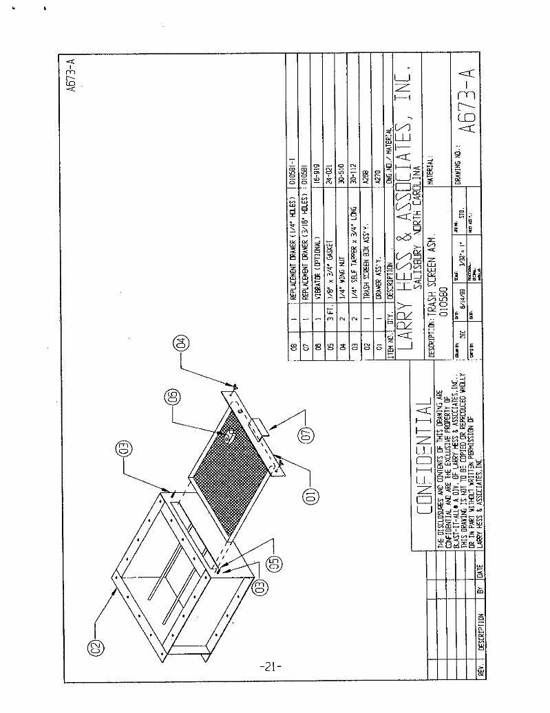
A. Clean trash screen and empty.
B. Empty dust bag or dust collector 4-4 Weekly Inspection:
A. Dust bags in dust collector B. Blast nozzle for wear C. Machine door gaskets D. Reclaimer door gasket E. Air hoses for leaks and loose clamps F. Blast hose for holes or soft spots
4-5 As Needed:
A. Add media B. Replace bags
C. Replace worn gloves D. Replace window F. Replace any worn or defective blast parts G. Replace gaskets H. Replace hoses
PAGE 7
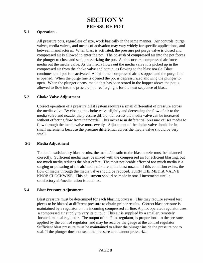
SECTION V PRESSURE POT 5-1 Operation -
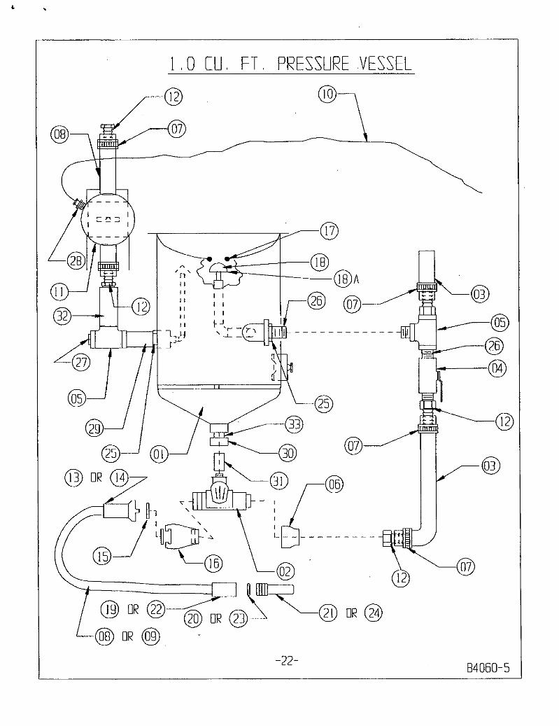
All pressure pots, regardless of size, work basically in the same manner. Air controls, purge valves, media valves, and means of activation may vary widely for specific applications, and between manufactures. When blast is activated, the pressure pot purge valve is closed and compressed air is allowed to enter the pot. The on-rush of compressed air into the pot forces the plunger to close and seal, pressurizing the pot. As this occurs, compressed air forces media out the media valve. As the media flows out the media valve it is picked up in the compressed air from the choke valve and continues flowing to the blast nozzle. Blast continues until pot is deactivated. At this time, compressed air is stopped and the purge line is opened. When the purge line is opened the pot is depressurized allowing the plunger to open. When the plunger opens, media that has been stored in the hopper above the pot is allowed to flow into the pressure pot, recharging it for the next sequence of blast.
5-2 Choke Valve Adjustment
Correct operation of a pressure blast system requires a small differential of pressure across the media valve. By closing the choke valve slightly and decreasing the flow of air to the media valve and nozzle, the pressure differential across the media valve can be increased without effecting flow from the nozzle. This increase in differential pressure causes media to flow through the media valve more evenly. Adjustment of the choke valve should be in small increments because the pressure differential across the media valve should be very small.
5-3 Media Adjustment
To obtain satisfactory blast results, the media/air ratio to the blast nozzle must be balanced correctly. Sufficient media must be mixed with the compressed air for efficient blasting, but too much media reduces the blast effect. The most noticeable effect of too much media is a surging or pulsating of the air/media mixture at the blast nozzle. If this condition exists, the flow of media through the media valve should be reduced. TURN THE MEDIA VALVE KNOB CLOCKWISE. This adjustment should be made in small increments until a satisfactory air/media ration is obtained.
5-4 Blast Pressure Adjustment
Blast pressure must be determined for each blasting process. This may require several test pieces to be blasted at different pressure to obtain proper results. Correct blast pressure is maintained by a regulator on the incoming compressed air line. A pilot operated regulator uses a compressed air supply to vary its output. This air is supplied by a smaller, remotely located, manual regulator. The output of the Pilot regulator, is proportional to the pressure applied by the control regulator, and may be read by the gauge at the control regulator. Sufficient blast pressure must be maintained to allow the plunger inside the pressure pot to seal. If the plunger does not seal, the pressure tank cannot pressurize.
PAGE 8
SECTION VI
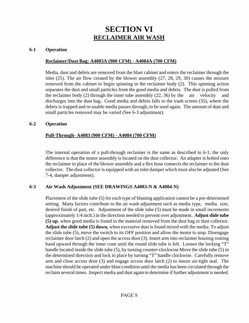
RECLAIMER AIR WASH 6-1 Operation
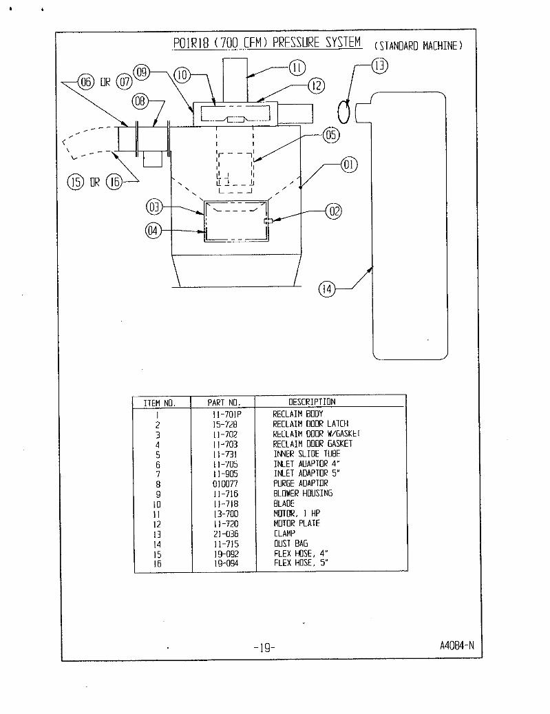
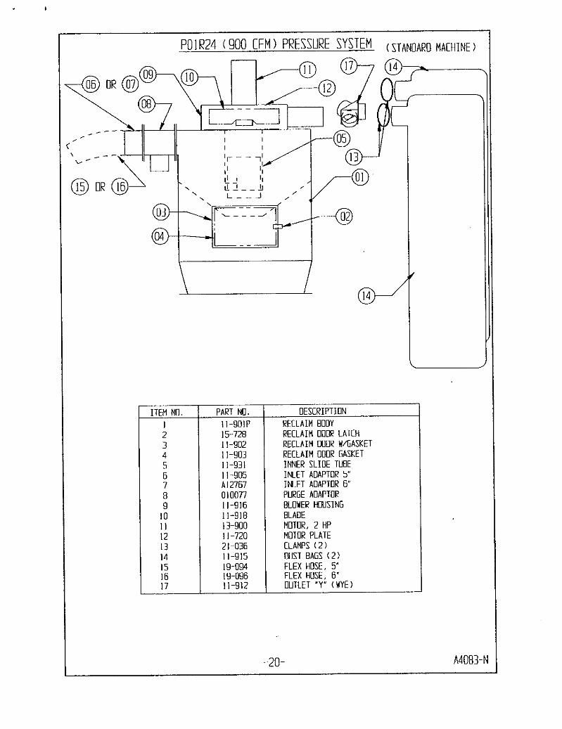
Reclaimer/Dust Bag: A4083A (900 CFM) - A4084A (700 CFM)
Media, dust and debris are removed from the blast cabinet and enters the reclaimer through the inlet (25). The air flow created by the blower assembly (27, 28, 29, 30) causes the mixture removed from the cabinet to begin spinning in the reclaimer body (2). This spinning action separates the dust and small particles from the good media and debris. The dust is pulled from the reclaimer body (2) through the inner tube assembly (22, 36) by the air velocity and discharges into the dust bag. Good media and debris falls to the trash screen (35), where the debris is trapped and re-usable media passes through, to be used again. The amount of dust and small particles removed may be varied (See 6-3 adjustment).
6-2 Operation
Pull-Through- A4083 (900 CFM) - A4084 (700 CFM)
The internal operation of a pull-through reclaimer is the same as described in 6-1; the only difference is that the motor assembly is located on the dust collector. An adapter is bolted onto the reclaimer in place of the blower assembly and a flex hose connects the reclaimer to the dust collector. The dust collector is equipped with an inlet damper which must also be adjusted (See 7-4, damper adjustment).
6-3 Air Wash Adjustment (SEE DRAWINGS A4083-N & A4084-N)
Placement of the slide tube (5) for each type of blasting application cannot be a pre-determined setting. Many factors contribute to the air wash adjustment such as media type, media size, desired finish of part, etc. Adjustment of the slide tube (5) must be made in small increments (approximately 1/4 inch.) in the direction needed to prevent over adjustment. Adjust slide tube (5) up, when good media is found in the material removed from the dust bag or dust collector. Adjust the slide tube (5) down, when excessive dust is found mixed with the media. To adjust the slide tube (5), move the switch to its OFF position and allow the motor to stop. Disengage reclaimer door latch (2) and open the access door (3). Insert arm into reclaimer housing routing hand upward through the inner cone until the round slide tube is felt. Loosen the locking “T” handle located inside the slide tube (5), by turning counter-clockwise Move the slide tube (5) in the determined direction and lock in place by turning “T” handle clockwise. Carefully remove arm and close access door (3) and engage access door latch (2) to insure air-tight seal. The machine should be operated under blast condition until the media has been circulated through the reclaim several times. Inspect media and dust again to determine if further adjustment is needed.
PAGE 9
SECTION VII
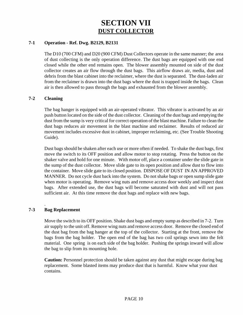
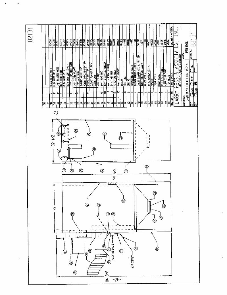
DUST COLLECTOR 7-1 Operation - Ref. Dwg. B2129, B2131
The D10 (700 CFM) and D20 (900 CFM) Dust Collectors operate in the same manner; the area of dust collecting is the only operation difference. The dust bags are equipped with one end closed while the other end remains open. The blower assembly mounted on side of the dust collector creates an air flow through the dust bags. This airflow draws air, media, dust and debris from the blast cabinet into the reclaimer, where the dust is separated. The dust-laden air from the reclaimer is drawn into the dust bags where the dust is trapped inside the bags. Clean air is then allowed to pass through the bags and exhausted from the blower assembly.
7-2 Cleaning
The bag hanger is equipped with an air-operated vibrator. This vibrator is activated by an air push button located on the side of the dust collector. Cleaning of the dust bags and emptying the dust from the sump is very critical for correct operation of the blast machine. Failure to clean the dust bags reduces air movement in the blast machine and reclaimer. Results of reduced air movement includes excessive dust in cabinet, improper reclaiming, etc. (See Trouble Shooting Guide).
Dust bags should be shaken after each use or more often if needed. To shake the dust bags, first move the switch to its OFF position and allow motor to stop rotating. Press the button on the shaker valve and hold for one minute. With motor off, place a container under the slide gate in the sump of the dust collector. Move slide gate to its open position and allow dust to flow into the container. Move slide gate to its closed position. DISPOSE OF DUST IN AN APPROVED MANNER. Do not cycle dust back into the system. Do not shake bags or open sump slide gate when motor is operating. Remove wing nuts and remove access door weekly and inspect dust bags. After extended use, the dust bags will become saturated with dust and will not pass sufficient air. At this time remove the dust bags and replace with new bags. .
7-3 Bag Replacement
Move the switch to its OFF position. Shake dust bags and empty sump as described in 7-2. Turn air supply to the unit off. Remove wing nuts and remove access door. Remove the closed end of the dust bag from the bag hanger at the top of the collector. Starting at the front, remove the bags from the bag holder. The open end of the bag has two coil springs sewn into the felt material. One spring is on each side of the bag holder. Pushing the springs inward will allow the bag to slip from its mounting hole.
Caution: Personnel protection should be taken against any dust that might escape during bag
replacement. Some blasted items may produce dust that is harmful. Know what your dust contains.
PAGE 10
To install new bags, begin by hanging the bags on the bag hanger using the loop sewn into the closed end of the bag. With the bags hanging in place, begin at the rear of the machine installing the open end of the dust bag into the bottom bag holder. Place one spring on each side of the bag holder metal. Working forward, install all bags carefully into their respective hole being careful not to cross any bags. Do not use any sharp object to install bags in bag holder. When all bags have been installed correctly, inspect and replace any worn gasket around the access door. Re-install door and tighten all wing nuts. When the blast machine is restarted, observe the exhaust from the blower for traces of dust. If dust is detected, remove access door and inspect bag installation and dust bags.
7-4 Damper Adjustment
Due to increased efficiency over the standard dust bag, the D10 and D20 dust collectors are equipped with an inlet damper. The inlet damper has an external adjustable handle which can be locked in place with a wing nut. The inlet damper should be open enough to maintain sufficient air flow for correct reclaiming and to clean dust from the cabinet. If inlet damper is open too far, it will tend to pull good media out of the reclaimer. Inspection of the dust removed from the dust collector will determine if the damper is open too far. A correct balance of the inlet damper of the dust collector and the air wash in the reclaimer will produce maximum use of selected media.
SECTION VIII Safety Blast Control
8-1 Operation
A. Air Operated A safety air valve is located above each cabinet door. This valve is activated when
door(s) are closed.
WARNING: By-passing safety valve could cause a hazardous condition to personnel
PAGE 11
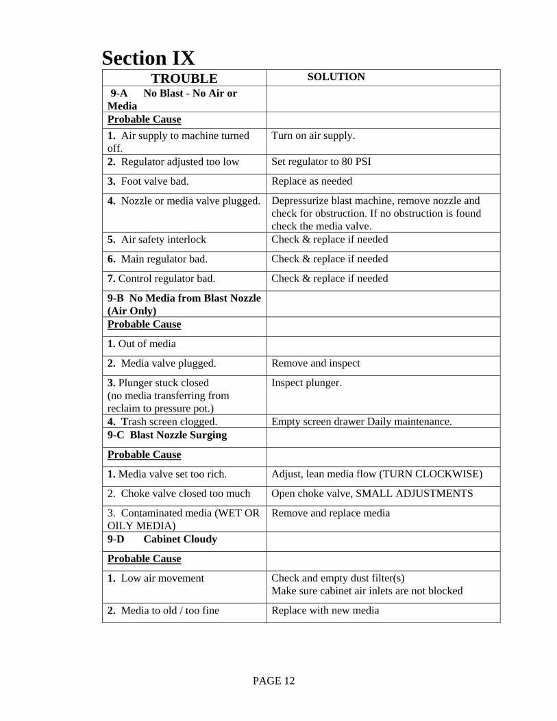
Section IX TROUBLE SOLUTION
9-A No Blast - No Air or Media
Probable Cause 1. Air supply to machine turned off.
Turn on air supply.
2. Regulator adjusted too low Set regulator to 80 PSI
3. Foot valve bad. Replace as needed
4. Nozzle or media valve plugged. Depressurize blast machine, remove nozzle and check for obstruction. If no obstruction is found check the media valve.
5. Air safety interlock Check & replace if needed
6. Main regulator bad. Check & replace if needed
7. Control regulator bad. Check & replace if needed
9-B No Media from Blast Nozzle (Air Only)
Probable Cause
1. Out of media
2. Media valve plugged. Remove and inspect
3. Plunger stuck closed (no media transferring from reclaim to pressure pot.)
Inspect plunger.
4. Trash screen clogged. Empty screen drawer Daily maintenance. 9-C Blast Nozzle Surging
Probable Cause
1. Media valve set too rich. Adjust, lean media flow (TURN CLOCKWISE)
2. Choke valve closed too much Open choke valve, SMALL ADJUSTMENTS
3. Contaminated media (WET OR OILY MEDIA)
Remove and replace media
9-D Cabinet Cloudy
Probable Cause
1. Low air movement Check and empty dust filter(s) Make sure cabinet air inlets are not blocked
2. Media to old / too fine Replace with new media
PAGE 12
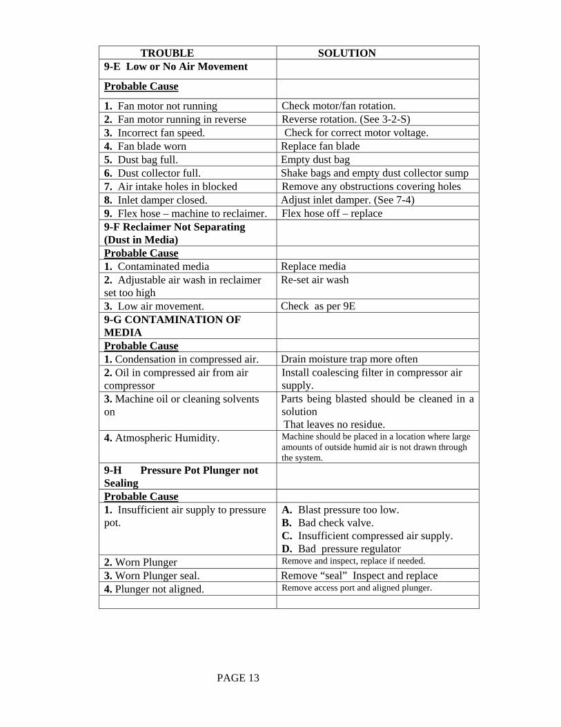
TROUBLE SOLUTION
9-E Low or No Air Movement
Probable Cause
1. Fan motor not running Check motor/fan rotation. 2. Fan motor running in reverse Reverse rotation. (See 3-2-S) 3. Incorrect fan speed. Check for correct motor voltage. 4. Fan blade worn Replace fan blade 5. Dust bag full. Empty dust bag 6. Dust collector full. Shake bags and empty dust collector sump 7. Air intake holes in blocked Remove any obstructions covering holes 8. Inlet damper closed. Adjust inlet damper. (See 7-4) 9. Flex hose – machine to reclaimer. Flex hose off – replace 9-F Reclaimer Not Separating (Dust in Media)
Probable Cause 1. Contaminated media Replace media 2. Adjustable air wash in reclaimer set too high
Re-set air wash
3. Low air movement. Check as per 9E 9-G CONTAMINATION OF MEDIA
Probable Cause 1. Condensation in compressed air. Drain moisture trap more often 2. Oil in compressed air from air compressor
Install coalescing filter in compressor air supply.
3. Machine oil or cleaning solvents on
Parts being blasted should be cleaned in a solution That leaves no residue.
4. Atmospheric Humidity. Machine should be placed in a location where large amounts of outside humid air is not drawn through the system.
9-H Pressure Pot Plunger not Sealing
Probable Cause 1. Insufficient air supply to pressure pot.
A. Blast pressure too low. B. Bad check valve. C. Insufficient compressed air supply. D. Bad pressure regulator
2. Worn Plunger Remove and inspect, replace if needed.
3. Worn Plunger seal. Remove “seal” Inspect and replace 4. Plunger not aligned. Remove access port and aligned plunger.
PAGE 13
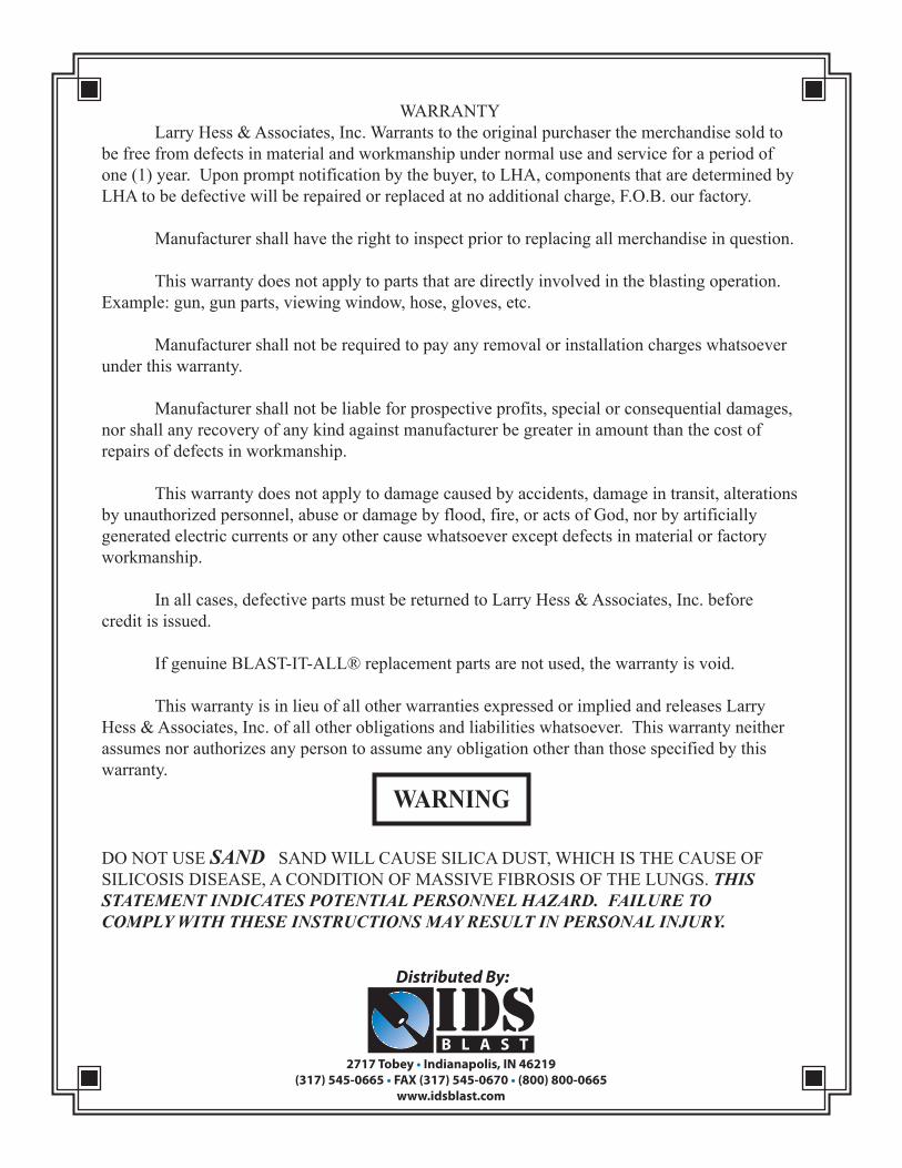
WARRANTY Larry Hess & Associates, Inc. Warrants to the original purchaser the merchandise sold to be free from defects in material and workmanship under normal use and service for a period of one (1) year. Upon prompt notification by the buyer, to LHA, components that are determined by LHA to be defective will be repaired or replaced at no additional charge, F.O.B. our factory.
Manufacturer shall have the right to inspect prior to replacing all merchandise in question.
This warranty does not apply to parts that are directly involved in the blasting operation.Example: gun, gun parts, viewing window, hose, gloves, etc.
Manufacturer shall not be required to pay any removal or installation charges whatsoever under this warranty.
Manufacturer shall not be liable for prospective profits, special or consequential damages, nor shall any recovery of any kind against manufacturer be greater in amount than the cost of repairs of defects in workmanship.
This warranty does not apply to damage caused by accidents, damage in transit, alterations by unauthorized personnel, abuse or damage by flood, fire, or acts of God, nor by artificially generated electric currents or any other cause whatsoever except defects in material or factory workmanship.
In all cases, defective parts must be returned to Larry Hess & Associates, Inc. before credit is issued.
If genuine BLAST-IT-ALL® replacement parts are not used, the warranty is void.
This warranty is in lieu of all other warranties expressed or implied and releases Larry Hess & Associates, Inc. of all other obligations and liabilities whatsoever. This warranty neither assumes nor authorizes any person to assume any obligation other than those specified by this warranty.
DO NOT USE SAND SAND WILL CAUSE SILICA DUST, WHICH IS THE CAUSE OF SILICOSIS DISEASE, A CONDITION OF MASSIVE FIBROSIS OF THE LUNGS. THIS STATEMENT INDICATES POTENTIAL PERSONNEL HAZARD. FAILURE TO COMPLY WITH THESE INSTRUCTIONS MAY RESULT IN PERSONAL INJURY.