blcen ethernet/iptm - pdb2.turck.de · 12 bootp/dhcp mode (93/94) the device obtains ip address...
TRANSCRIPT

BLCEN EtherNet/IPTM
Configuration Guide Version: 2.7.1
555T00006 11/2/2016

2
Contents
About this Guide ......................................................................................................................... 3
BLCEN Stations ............................................................................................................................ 4 Introduction ............................................................................................................................................. 4 BLCEN Common Features ........................................................................................................................ 4 BLCEN Product Design ............................................................................................................................. 4 Part Number Scheme .............................................................................................................................. 5 Data sheet ................................................................................................................................................ 6 Connection Diagrams .............................................................................................................................. 7 LED Diagnostics ........................................................................................................................................ 9 IO Data Structure ................................................................................................................................... 10 BLCEN-8M12LT-4AI-VI-8XSG-P IO data map.......................................................................................... 10
IP Address Setup ....................................................................................................................... 11 Default IP Address ................................................................................................................................. 11 Address Switches ................................................................................................................................... 11 BOOTP/DHCP Mode (93/94).................................................................................................................. 12 PGM-DHCP Mode (96) ........................................................................................................................... 13 PGM Mode (95) ..................................................................................................................................... 13 PGM (95) and Web Server ..................................................................................................................... 14 PGM (95) and TURCK IP address tool .................................................................................................. 17 RESTORE Mode (0) ................................................................................................................................. 18 RECOVERY Mode (99) ............................................................................................................................ 18
TURCK_BLOCK_STATIONS Catalog File ...................................................................................... 19 Download Catalog Files ......................................................................................................................... 19 Catalog File Distribution ........................................................................................................................ 21 Catalog File Content .............................................................................................................................. 23
Configure BLCEN using Catalog File ........................................................................................... 24 BLCEN Configuration Tag ....................................................................................................................... 26 BLCEN Input / Output Tags .................................................................................................................... 27 Read Parameters - Web Server ............................................................................................................. 28 Write Parameters - Web Server ............................................................................................................ 29

3
About this Guide
Following document is about configuration of the EtherNet/IP version of the BLCEN product family on AB ControlLogix and CompactLogix PLCs. The document applies to all BLCEN devices with the composite firmware revision 3.3.2.0. This revision supports device web server pages for the IO setup and monitoring.
The document is utilizing features of BLCEN-8M12LT-4AI-VI-8XSG-P station to
configure device using TURCK_BLOCK_STATIONS catalog file(s).

4
BLCEN Stations Introduction The BLCEN series are multiprotocol communication adapters which support multiple Ethernet standards: Modbus TCP/IP, EtherNet/IP and PROFINET. The factory default, “out of the box” setting, is that all Ethernet protocols are enabled. After power up, a multiprotocol station is listening on all necessary ports to detect on which kind of network it is used. The “Active Fieldbus Protocol” is defined as the first protocol to do one of the following actions:
Modbus TCP - Write to output register range.
EtherNet/IP - Establish Class 1 Exclusive Owner connection to device.
PROFINET RT - Connect request.
This “Configuration Guide” describes features and configuration procedure of the BLCEN series, using for example configuration of BLCEN-8M12LT-4AI-VI-8XSG-P in the EtherNet/IP network.
BLCEN Common Features The BLCEN common features are:
Support 3 protocols: EtherNet/IP, Modbus TCP/IP, PROFINET
ACD (Address Conflict Detection)
DLR (Device Level Ring)
QC (QuickConnect)
Two D-coded Ethernet ports ETH1 and ETH2. and embedded multiport switch
Two M12 24VDC power connectors, pass-through
Two rotary address switches
Advanced Web server
Device configuration using CIP Bridging and device “Catalog” file
1 or 2 slot housing accommodates up to two IO modules
Cost effective, flexible design, allows different combination of discrete, analog or
technology modules
BLCEN Product Design The BLCEN series is designed to accommodate up to two IO modules utilizing two different housing styles. The IO modules originate from BL67 product family1 thus providing standardization of IO modules across different applications. Two style IO connectors, M8 or M12, provide connection for a single or dual IO signals. Detailed device information is provided by the device data sheet.
1 BL67 User Manual – I/O Modules, D300529 2009

5
Part Number Scheme
6
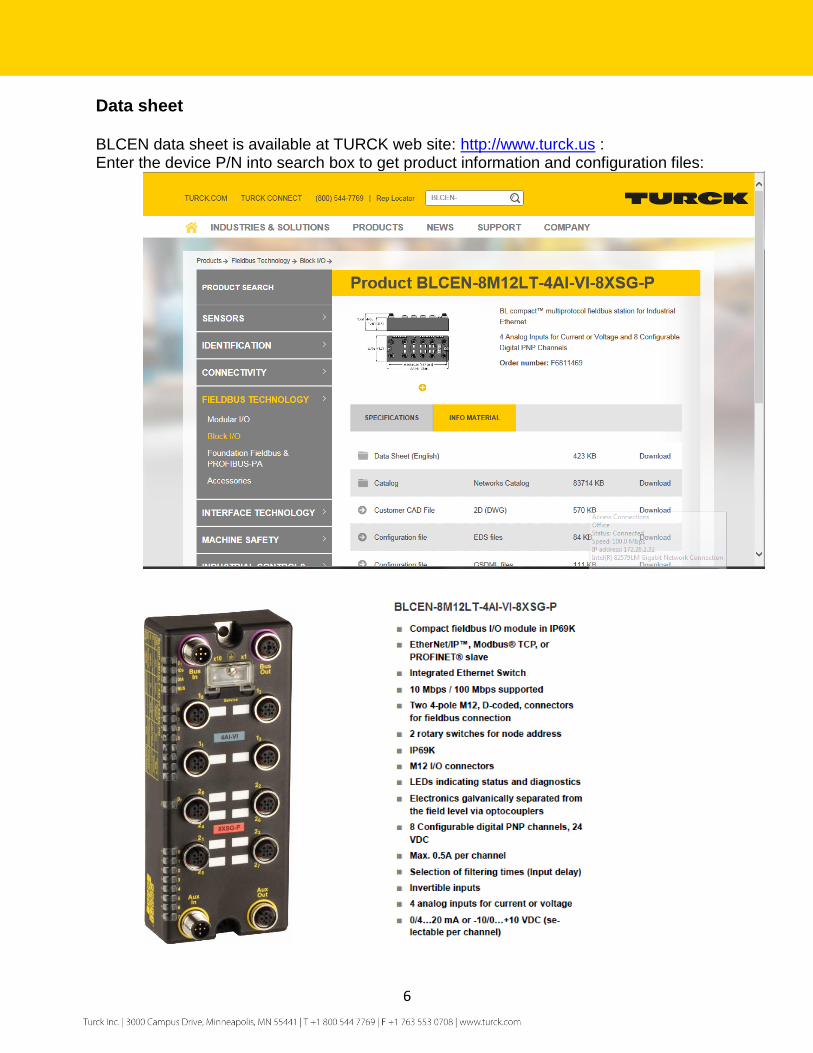
Data sheet BLCEN data sheet is available at TURCK web site: http://www.turck.us : Enter the device P/N into search box to get product information and configuration files:

7
Connection Diagrams Ethernet connectors:
IO connectors - slot 1:

8
IO connectors - slot 2:
AUX power connectors:
9
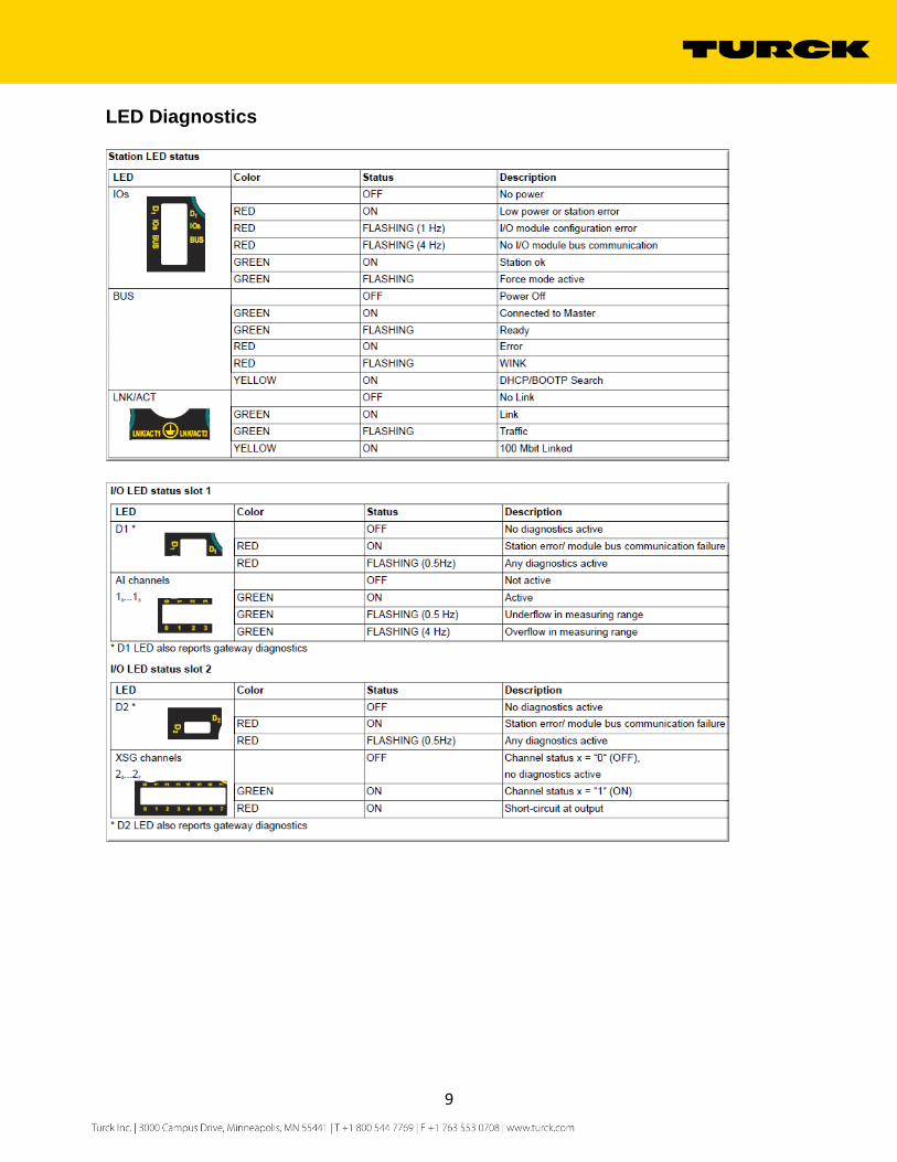
LED Diagnostics

10
IO Data Structure Refer to the station data sheet for information on exact IO data map.
BLCEN-8M12LT-4AI-VI-8XSG-P IO data map Input data map contains input and diagnostic data as follows:
Abbreviations: AI 1x Slot 1, analog input “x”, x=[0,1,2,3] LSB least significant byte MSB most significant byte DI 2y Slot 2, discrete input “y”, y=[0,1,…,7] Module number reporting diagnostic data = [1, 2] Diagnostic active bit, used in combination with module number Range error AI 1x Measurement range error, overflow / underflow2 Open Circuit AI 1x Current measurement < 4mA DO 2y Slot 2, discrete output “y”, y=[0,1,…,7] The device IO data not effectively used (up to 48 words) is populated by 0’s.
2 D300529 – BL67 User Manual IO Modules

11
IP Address Setup The general procedure for IP address setup is:
Set rotary switches to desired position
Cycle (reset) power to the station
Run IP address utility to assign IP address
Set address switches to rotary mode or PGM mode
Cycle power to the station
When address switches are in rotary mode, the last octet may be dialed in 1-92 range. Some address positions are reserved for dedicated functions.
Default IP Address The default IP address, when rotary switches are set to 0:
IP-address 192.168.1.254
Subnet mask 255.255.255.0
Default gateway 192.168.1.1
To reset IP address to the default, set address switches to 0 and cycle device power. Upon reset, set rotary switches to one of the modes as described hereafter.
Address Switches The BLCEN has two rotary switches marked as follows:
x10 sets the last digit of IP address to a 10’s value x1 sets the last digit of IP address to a 1’s value
Switch position determines either address or device mode of operation as follows:
0 - 192.168.1.254 1- 92 - Rotary mode 1..92 93 - BOOTP 94 - DHCP 95 - PGM 96 - PGM-DHCP 97- 99 - Vendor specific address
When using the static rotary mode, the last octet of the module’s IP address can be set via the rotary coding-switches in 1…92 range. The 100, …, 254 range is also available when rotary switches are set to PGM mode after assigning address using BOOTP, DHCP, PGM or PGM-DHCP mode. After running either mode, set rotary switches to PGM mode and cycle the power. The device retains assigned address in the TCP/IP object.

12
BOOTP/DHCP Mode (93/94) The device obtains IP address from the BOOTP or DHCP servers when address switches are set to 93 (BOOTP) or 94 (DHCP) position. The IP address, as well as the subnet mask assigned to the station, is stored in the device’s EEPROM. When the station is subsequently switched to rotary or PGM mode and its power reset, the IP address is read from the EEPROM.

13
PGM-DHCP Mode (96) When the rotary switches are set to 96 it enables PGM–DHCP mode of operation. This mode is the out-of-the-box mode and provides the customer with powerful and convenient IP address setup. Procedure is the identical to DHCP mode. When finished, click on “Disable BOOTP/DHCP” button. Leave address switches in 96 position and cycle power. The IP address is read from the EEPROM memory.
PGM Mode (95) When the rotary switches are set to 95 (PGM mode), the device will use either the factory default IP address on the first power-up or maintain current IP address whatever it is. While in the PGM mode, the device IP address may be changed, with software tools like:
Device WEB server
TURCK IP address tool
IOAssistant configuration tool

14
PGM (95) and Web Server
Set address switches to 95 and power-up device
Enter current IP address of the device into a Web browser (e.g. 192.168.1.36)
Sign-in as administrator; enter “password” into “Password” field and press Login. It will
enable read/write access to the device various parameters
The left-hand portion of the main page provides access to different device information, a few to mention:
Note that the composite firmware revision, which includes all device components, is
3.3.2.0
EtherNet/IP firmware revision is 2.7.15.0
“Addressing mode” indicates position of the address switches

15
The web server main page, when signed-in as the administrator, has additional entries like “Gateway Configuration and Network Configuration” pages:

16
The “network configuration” page provides administrator’s access to Ethernet address setup:
Select “Network Configuration” at the left column
Enter new IP address e.g. 192.168.1.136 and press “Submit”
Leave rotary switches in 95 position
The device immediately comes up with the new IP address:

17
PGM (95) and TURCK IP address tool TURCK IP address tool is used to search devices on the Ethernet network, identify devices using “Wink” command, change Ethernet address and reset device.
Start the IP address tool and press search
BLCEN is discovered at IP 192.168.1.136 (mode is PGM)
Highlight device, press “Change” , enter new IP address and press “Write to device”
Device comes up immediately with the new IP address:

18
RESTORE Mode (0) The RESTORE mode (0) is a special mode which restores the IP address to the factory default values, but leaves other device parameters as they are. Station responds to PING command, but it does not operate when switches are set to 0. Set address to 0 and cycle the power to the station to restore following values:
IP address: 192.168.1.254
Mask: 255.255.255.0
Gateway: 192.168.1.1
Set rotary switches to any position as previously described and cycle device power.
RECOVERY Mode (99) The RECOVERY mode (99) is a special mode which resets all device resources to factory default values. It will clear all previously assigned parameter values to the gateway and IO modules. Set rotary switches to 99 and cycle the power to the station. Wait for a moment, set rotary switches as previously described and cycle device power again.

19
TURCK_BLOCK_STATIONS Catalog File Download Catalog Files A catalog file is RSLogix5000 project which contains predefined configurations of block IO stations. Go to TURCK web site and enter “BLCEN” into search area:
Select device and click on name /link:
20
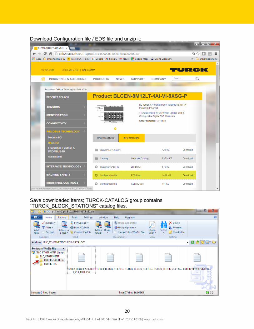
Download Configuration file / EDS file and unzip it:
Save downloaded items; TURCK-CATALOG group contains “TURCK_BLOCK_STATIONS” catalog files.

21
Catalog File Distribution The catalog files are distributed as “L5K” files and they are named as follows:
The files are created for users that may have different versions of RSLogix5000 or Studio5000 programming software. For example RSLogix5000 Lite or Mini version operates only CompactLogix PLCs. If you have RSLogix5000 / Studio5000 full edition, you may use any catalog file.
The catalog file “TURCK_BLOCK_STATIONS_V19_LITE.ACD” will be used throughout this document. It is based on the following entries:
- 1768-L45 CompactLogix 5345 controller
- 1768-ENBT Ethernet bridges
- The BLOCK_IO Ethernet bridge contains configurations of FEN20, TBEN-Lx, TBEN-Sx,
FGEN, FXEN
- The BLCEN Ethernet bridge contains configurations of all BLCEN stations

22
L5K file are imported into project as follows: - Start new project and select “Open”
- Go to location where you saved L5K files, highlight file to open and click “Open”:
- Click “Import” to save file into your location:

23
Catalog File Content “TURCK_BLOCK_STATIONS_V19_LITE.ACD”catalog file or project contains configurations of the following Turck stations, preconfigured using generic device profile:

24
Configure BLCEN using Catalog File The first step is to configure BLCEN with the controller. Open both your online project and the catalog in separate windows. Expand the “1768-ENTB/A BLCEN” bridge in the catalog and drag the “BLCEN_8M12LT_4AI_VI_8XSG_P” ”device from the catalog into your project into Ethernet group.

25
Highlight “ETHERNET-MODULE BLCEN_....” in the Controller Organizer and open “Module Properties” page:
The device is renamed as “BLCEN_X” and assigned an IP address of 192.168.1.36.
Click Apply and OK to complete device configuration.

26
BLCEN Configuration Tag Once the device is configured following tags are created:
The configuration tag BLCEN_X:C provides access to parameters used for IO module configuration, e.g. measurement range description shows: “Slot 1 - Analog In 0 - Measurement range (ENUM bit0): 0=0...10 V/0...20 mA, 1=-10...10 V/4...20 mA” where:
1: -10...10 V/4...20 mA range 0: 0...10 V/0...20 mA range
Note: Use the configuration tag to configure IO modules. The configuration is downloaded to the device from the controller each time communication with the device is established.

27
BLCEN Input / Output Tags Input tag provides multiple entries, like measurements:
Diagnostics:
Output tag:

28
It is important to emphasize that parameterization of the device IO ports has to be done using the configuration tag of your main project. DO NOT use web server or PACTware to do IO parameterization, because it will be overwritten during project download to the PLC, or after power-up of the station. The device Web server and/or PACTware may be used:
- To read current IO setup when device is connected to a PLC
- To read and write parameters during IO test when device is not connected to a PLC
Read Parameters - Web Server To read IOL parameters, open the main page and expand parameters entries:

29
Write Parameters - Web Server Log-in as administrator by entering “password”:
Select IO channel to configure, Analog In 0, and select operation mode: voltage or current.
Submit setting at the end.

30
Restore parameter(s) setup to the factory defaults, press “Reset to Factory Defaults”:

31
Factory default parameterization: