bldc motor operation control.pdf
TRANSCRIPT

7/29/2019 bldc motor operation control.pdf
http://slidepdf.com/reader/full/bldc-motor-operation-controlpdf 1/46
Model 4000 Instruction Manual Page v
Mailing Address: P.O. Box 2650 * Rock Hill, South Carolina USA 29732 * PHONE: 803-328-1888Shipping Address: 2606 Eden Terrace * Rock Hill, South Carolina USA 29730 * FAX: 803-328-187
www.powertecmotors.com
POWER TEC Publication # 4000NRIM
MADE IN USA
BRUSHLESS D.C.MOTOR CONTROL
INSTALLATION AND OPERATIONINSTRUCTION MANUAL
APRIL 12, 1993

7/29/2019 bldc motor operation control.pdf
http://slidepdf.com/reader/full/bldc-motor-operation-controlpdf 2/46
7/29/2019 bldc motor operation control.pdf
http://slidepdf.com/reader/full/bldc-motor-operation-controlpdf 3/46
Model 4000 Instruction Manual Page
MODEL 4000 INSTRUCTION MANUAL
TABLE OF CONTENTS
LIST OF ILLUSTRATIONS......................................................................................................... iiSUMMARY OF WARRANTY .................................................................................................... iiiWARNING NOTICE .................................................................................................................... iiiPOWERTEC SCHOOLS .............................................................................................................. iii
1.0 INTRODUCTION1.1 BRUSHLESS MOTOR TECHNOLOGY .........................................................................11.2 NON-REGEN VERSUS REGEN OPERATION .............................................................21.3 A BRUSHLESS DC PRIMER ...........................................................................................31.4 BRUSHLESS MOTOR BENEFITS ..................................................................................71.5 HOW TO USE THIS MANUAL .......................................................................................7
2.0 APPLICATION DATA2.1 ELECTRICAL RATINGS .................................................................................................92.2 DIMENSIONS ....................................................................................................................92.3 ENVIRONMENTAL ..........................................................................................................92.4 PERFORMANCE ............................................................................................................ 102.5 CUSTOMER ADJUSTMENTS ...................................................................................... 102.6 INDICATORS.................................................................................................................. 102.7 TERMINAL DESCRIPTIONS ....................................................................................... 10
3.0 PHYSICAL INSTALLATION3.1 RECEIVING..................................................................................................................... 113.2 BEFORE INSTALLATION............................................................................................ 113.3 INSTALLATION ............................................................................................................. 123.4 THERMAL CONSIDERATIONS .................................................................................. 12
4.0 ELECTRICAL INSTALLATION4.1 GENERAL REQUIREMENTS....................................................................................... 13
4.2 POWER SUPPLY ............................................................................................................ 134.3 CONNECTING THE MOTOR ....................................................................................... 154.3.1 MOTOR LEADS................................................................................................ 154.3.2 MOTOR GROUND ........................................................................................... 154.3.3 OUTPUT CONTACTOR .................................................................................. 164.3.4 MOTOR FEEDBACK CABLE......................................................................... 16
4.4 CONTROL CONNECTIONS ......................................................................................... 164.5 REFERENCE OPTIONS................................................................................................. 18
4.5.1 ANALOG REFERENCE ................................................................................... 184.5.2 DIGITAL REFERENCE ................................................................................... 19
4.6 AUXILIARY CIRCUITS ................................................................................................ 204.7 P.L.C. INTERFACE ........................................................................................................ 22
5.0 OPERATION
5.1 ANALOG INPUT OPERATION.................................................................................... 235.1.1 SPEED REFERENCE ....................................................................................... 235.1.2 MINIMUM SPEED ........................................................................................... 235.1.3 ACCEL AND DECEL ....................................................................................... 245.1.4 MAXIMUM SPEED .......................................................................................... 245.1.5 RAMP STOP ...................................................................................................... 255.1.6 JOG FUNCTION ............................................................................................... 255.1.7 BI-DIRECTIONAL JOG ................................................................................... 25

7/29/2019 bldc motor operation control.pdf
http://slidepdf.com/reader/full/bldc-motor-operation-controlpdf 4/46
Page ii copyright 1993, 1994 by POWER TECIndustrial Corporation Used by permission
1. Comparison of speed regulation................12. Stopping methods compared........................23. Input power section..............................................34. Power output bridge.............................................35. Single wye motor connections.....................46. Simplified drawing of motor ...........................47. Current flow at turn-on.......................................58. Motor rotation result.............................................59. The encoder assembly.......................................6
10. Parts layout of the Model 4000...................811. 4000 Chassis dimensions.............................1112. 4000 NEMA 1 dimensions............................1213. Standard connections......................................1414. Input power connections...............................1515. Output contactor ..................................................1616. Digital mode inputs............................................1917. Frequency output ................................................2018. Follower connection..........................................20
TABLE OF CONTENTS (continued)
5.0 OPERATION (CONTINUED)
5.2 DIGITAL MODE ............................................................................................................. 265.3 CURRENT LIMIT ........................................................................................................... 265.4 GAIN AND STABILITY ................................................................................................ 27
6.0 THEORY AND TROUBLESHOOTING6.1 INPUT POWER SECTION ............................................................................................ 296.2 CHARGING SECTION................................................................................................... 296.3 CURRENT SENSOR BOARD ....................................................................................... 306.4 POWER OUTPUT SECTION ........................................................................................ 316.5 CURRENT CONTROLLER BOARD ............................................................................ 336.6 SPEED CONTROLLER .................................................................................................. 346.7 TROUBLESHOOTING ................................................................................................... 35
7.0 SPARE PARTS ............................................................................................................................ 39
19. Auxiliary RUN relay...........................................2020. FAULT relay............................................................2121. ENABLE relay........................................................2122. ZERO SPEED relay...........................................2123. Chatter elimination.............................................2224. SINKING connection to PLC......................2225. SOURCING connection to PLC................2226. Connecting FAULT output to PLC.........2227. Connections for minimum speed............2328. Simplified drawing of power circuits....2829. Parts layout of Current Sensor board.3030. Layout of Base Driver board......................3131. Block diagram of the 4000...........................3232. Current Controller board layout...............3333. Speed Controller board layout..................3434. Typical configurations of semiconductors3735. Connections to DIGIMAX IV.......................38
LIST OF ILLUSTRATIONS

7/29/2019 bldc motor operation control.pdf
http://slidepdf.com/reader/full/bldc-motor-operation-controlpdf 5/46
Model 4000 Instruction Manual Page ii
SUMMARY OF WARRANTY AND DISCLAIMER
POWER TEC Industrial Corporation guarantees the Model 4000 Brushless DC motor controls which itmanufactures to be free from defects in materials and workmanship for a period of one year from the date ooriginal shipment, or, if purchased from an authorized distributor or original equipment manufacturer, for nomore than 18 months from the date of original shipment from the factory. Upon written notification to the factoryof a defect in materials or workmanship in a warranted unit, POWER TEC will, at its sole option, repair orreplace at the factory such defective parts as it deems necessary to restore the unit to service. Shipping chargesto and from the factory, taxes, and duties are the responsibility of the user.
There is no other warranty, expressed or implied, including fitness of purpose for the application intendedThis warranty does not cover accidental or intentional damage, accidental or intentional abuse, effects fromdefective or incorrect installation, effects on other equipment, or any other situation over which POWER TEChas no control.
This warranty does not encompass any other claims, including, but not limited to, special, incidental, orconsequential damages.
This manual has been written as a guide to the use of POWER TEC products. It represents the best effortsto compile the information contained herein. Such mistakes as may appear in no way affect the above stated
warranty. If mistakes of fact are found in this manual, please notify your distributor or POWER TEC at once
POWER TEC SCHOOLS
POWER TEC Industrial Corporation conducts periodic service schools to promote the training andunderstanding of its customers, representatives, and distributors. These schools are held at the factory in RockHill, South Carolina. Schools at other locations may be arranged with the service department.
The two-day school at POWER TEC emphasizes basic concepts, block diagram and schematic studysystems application, and there is a hands on training period. Attendees also tour POWER TEC's modern newfacility and meet the people who serve their needs.
There is a nominal charge to cover the cost of materials. Also included are two lunches, a dinner, andsnacks. The person attending is responsible for lodging, other meals, and transportation to and from Rock HillSC (20 miles south of Charlotte, North Carolina).
For further information, PHONE: 803-328-1888or FAX: 803-328-1870
WARNING!!
THE POWER TEC MODEL 4000 OPERATES NORMALLY AT HIGH VOLTAGE
AND POWER LEVELS WHICH CAN CAUSE INJURY OR DEATH!
ONLY PERSONNEL QUALIFIED IN THE MAINTENANCE OF HIGH VOLTAGE, HIGH POWER
EQUIPMENT SHOULD WORK ON THESE CONTROLS.
BEFORE WORKING ON THIS EQUIPMENT, READ THIS ENTIRE MANUAL.

7/29/2019 bldc motor operation control.pdf
http://slidepdf.com/reader/full/bldc-motor-operation-controlpdf 6/46
Page iv copyright 1993, 1994 by POWER TECIndustrial Corporation Used by permission
7/29/2019 bldc motor operation control.pdf
http://slidepdf.com/reader/full/bldc-motor-operation-controlpdf 7/46
Page Model 4000 Instruction Manual
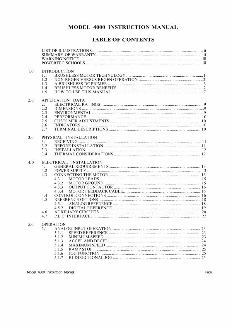
Figure 1: Comparison of speed regulation of typical
industrial motors from no load to full load.
1.1 BRUSHLESS DC MOTOR TECHNOLOGY
Traditional AC induction motors must “slip” (fall
behind their natural “synchronous” speed) in order todevelop torque. The synchronous speed is determined
by the frequency of the power at the motor terminals. At60 Hertz (the power line frequency in the USA) a four
pole AC induct ion motor will have a synchronous speedof 1800 RPM. With a full load on the motor, however,the motor will only be turning at 1740 RPM (curve A inFigure 1), due to the necessity of slip to develop torque.
An AC induction motor running near synchronousspeed does not develop any torque. The amount of slipvaries with the amount of torque required from themotor. Since slip is a percentage of the operating speed,and the amount of slip varies with the load, it is difficultto predict the speed at which an AC induction motor willrun under any given set of operating conditions, whether it is operated across-the-line or on the output of avariable frequency control. It is very difficult to main-
tain an exact speed when operating under varying loadconditions. Extraordinary means must be used to em-
ploy AC motors in speed sensitive applicat ions.Inverters do not help much with AC induction
motors, but they do improve speed regulation a little byincreasing the applied frequency as the load increases
(curve B in figure 1).Traditional brush-type DC motors are operatedusing mostly solid-state AC to DC power converterswhich have inherent limitations on their ability to pro-vide power when and as needed . At best they can supply
power on ly 360 t imes per s econd wi th t hree phase input power, or 120 t imes per second with s ingle phase input po wer. Worse, the brush- type DC motor is a se lf commutating device which uses the applied power inef-ficiently, and loses some of the power on the way to the
place where it real ly counts.
The speed of the DC motor is determined by thevoltage applied at the brushes where they come in con-tact with the commutator, which is a few windings, andmany voltage drops (known as IR losses), away from theoutput terminals of the motor control, where the motor' sCEMF (armature voltage) is often used to regulate speedSince the voltage differences between the brushes andthe motor control output vary with load, speed varieswith load. Extraordinary means must be used to employDC brush-type motors and solid-state SCR controls inspeed sensitive applications.
Even when a DC tachometer is used with a brush-type DC motor to regulate speed (curve C in Figur 1), thetachometer only reads an AVERAGE speed, and theresolution between speeds limits the response.
The Brushless DC motor and control system overcomes these problems to provide smooth and efficient
power and speed control. Its speed regulation is nomeasured in percentage of RPM, as is the case withother types of motor and control systems, but in physicashaft position within a single revolution. With a brush-type DC motor and solid state SCR control, speed regu-lation of +/-0.5% might be obtained with a very expen
sive tachometer. This means that a motor set for 1750RPM may be operating anywhere between 1741 RPMand 1759 RPM and still be within specifications. A
brushless DC motor set for 1750 RPM must run at 1750RPM, period. The only alternative is to be in currenlimit. Short of current limit, the brushless D.C. motormay not be more than 240 degrees behind its no loadshaft position with the standard control set at its mini-mum gain. The Brushless DC motor control does nolook at its speed, it looks at where the motor shaft is inrelation to where it should be.
The Brushless DC motor control also can supply power when and as needed at a rate which more than fivetimes the solid-state SCR control's line limited rate.
All of this comes in a compact package which wilexceed the performance of across the line operated ACmotors, AC adjustable frequency operated motors, orthe conventional DC brush-type motors.
POWER TEC's Brushless DC motors have the highreliability and low maintenance requirements whichhave always been associated with AC induction motorsBrushless D.C. motors have speed and torque controwhich are superior to the traditional brush-type DCmotor, plus a very high level of efficiency.
The Brushless DC motor and control give yourindustrial applications outstanding performance, longlife, and very efficient service in the the most demand-ing industrial conditions.
1.0 INTRODUCTION

7/29/2019 bldc motor operation control.pdf
http://slidepdf.com/reader/full/bldc-motor-operation-controlpdf 8/46
Page 2 copyright 1993, 1994 by POWER TECIndustrial Corporation Used by permission
1.2 NON-REGEN VS. REGEN OPERATION
The POWER TEC Model 4000 is a non-regen-erative Brushless DC motor control. They will not
accept any energy coming back from the motor due tooverhauling loads and high inertias during decelera-tion. The Model 4000RG from POWER TEC is regen-erative. This section explains the difference.
When a motor is operating with a load in such a waythat it is drawing current from the power supply, it is saidto be operating in the MOTORING mode. This is the mostcommon mode of motor operation, used to power industrial
processes in almost all applications. The motor is convert-ing the electrical energy from the plant power supply intomechanical energy (work) at the motor's output shaft.
When any electric motor rotates, it produces a poten-tial at its main terminals. This potential is due to the
movement of the rotor or armature windings through amagnetic field, as in the case of the brush type D.C. motor or the induction A.C. motor. This potential is called Counter-Electro-Motive-Force (CEMF, for short). CEMF is pro-duced by the motor even when it is drawing power from thesupply, and the CEMF tends to oppose the flow of currentfrom the supply to the motor. In the case of the brushlessD.C. motor, a field produced by the magnets on the rotor is
Figure 2: Stopping methods for motors compared.
moving around the stationary windings of the stator. If thevoltage produced by the rotation of the motor shaft (due tothe CEMF) exceeds the supply voltage, the motor can not
draw current from the supply as long as this situation exists.Usually this condition is produced when motor speed isgreater than the speed commanded by the reference, per-haps due to the amount of inertia of the load being greater than the amount of inertia which can be slowed by themotor in the time allotted, or when the load is being moved
by another force faster than the motor wants to turn.A load in motion will come to a free-wheeling stop by
“coasting” in an amount of time determined by the speed,inertia, and friction of the load. The faster a load is moving,the longer it requires to stop. Larger inertias (generallyspeaking, more mass) take longer to stop, but a higher friction load slows it down faster. A moving load stops in acoasting situation by dissipating the energy of motion asfrictional heat, which acts as a brake. If inertia is high andfriction is low, the load will take a longer time to stop.Mechanical brakes may be used to increase the amount of friction.
Non-regenerative motor controls do not have theability to slow down a load in a time which is less than themotor would normally slow down by itself, or come to astop, by coasting. It cannot act as a brake, so it shuts off andwaits for speed to fall below that commanded by thereference at the time (if the control is active). Braking forcemay be supplied by the motor by dissipating the energy into
passive resistors connected after the control is shut off (dynamic braking).
Regenerative motor controls are capable of supplying braking force while the motor control is active. A motor rotating at a speed which faster than its control is com-manding becomes a generator. The amount of power gener-ated is related to the speed, the total inertia, and the frictionof the load and motor combination.
It is also proportional to the dissipative and/or stor-age load presented by the controller, which must be ad-equate. The regenerative control will accept current fromthe motor, and will dissipate the energy received, as long asthe load it presents is sufficient to dissipate the energy.
When energy is being generated by the motor, and being accepted by the controller, then the motor is said to beREGENERATING. A motor in the regenerating mode
develops torque in the opposite direction of its rotation, andis not drawing power from the supply, as it is in themotoring mode.
Regenerative power capability gives the motor andcontrol the ability to change from higher speeds to lower speeds (including zero speed, and also including the rever-sal of motor direction) much more quickly than with non-regenerative types of controls, resulting in more rapid stopsand quick reversals of loads which would otherwise be a lotmore sluggish in these actions.

7/29/2019 bldc motor operation control.pdf
http://slidepdf.com/reader/full/bldc-motor-operation-controlpdf 9/46
Page Model 4000 Instruction Manual
1.3 A BRUSHLESS D.C. PRIMER
Three phase AC plant power is converted to DC by theinput side of a Brushless DC motor control to charge up a"bank" of storage capacitors (called the "buss"), whosefunction is to store energy and supply DC power to the
power transistors in the output bridge as power is required
by the motor. The size of the buss (the number of capaci-tors) varies with the size of the motor.
This rectification is accomplished by six diodes, which
may be in a single package or in several modules. Thediodes are protected by the input fuses, which are chosenfor their speed and interrupting capacity. An input choke inthe DC leg of the diode bridge protects against line tran-sients and limits the rate at which input current may in-crease or decrease.
This input section is self regulating. The highestvoltage level possible on the capacitors is 1.4 times theline-to line voltage (the peak voltage). Initially, before themotor is turned on, the capacitors will charge up to this peak
voltage. When the motor is started, it uses power from the buss to perform the work required. The effect of this is to partially discharge the capacitors, lowering the buss volt-age. With three phase input power, there are six periods ineach cycle of AC when the line-to line voltage is greater than the capacitor voltage. The capacitors will only drawcurrent from the power lines when the capacitor voltage islower than the instantaneous line-to-line voltage, and thenit will only draw enough power to replenish the energy used
by the motor since the last time the line-to line voltage wasgreater than the capacitor voltage.
Torque in a motor is a function of current. Power is afunction of speed AND torque. Even though the currentrequired by the motor to develop the torque may be large,the actual power used is small at low speeds. Because theenergy drawn from the capacitors is the actual power usedby the motor, the energy drawn from the input power linesis the actual power supplied to the motor. The BrushlessDC motor control is capable of running at very low speedsat very high torques while drawing very little current fromthe AC line. The result of this is that the RMS current at the
input of the Brushless DC motor control is directly propor-tional to the output power of the motor, rather than being
proportional to the motor's load.A Brushless DC motor is wound like an AC induction
motor, but it uses permanent magnets on the rotor instead o
shorted rotor bars. There are three power carrying wiresgoing to the motor. Each of these wires has to be, atsynchronized times, connected to either side of the DC
buss. This is accomplished with a six transistor poweroutput bridge configuration (figure 4).
Applying power to the motor requires turning on onetransistor connected to the positive side of the buss and onetransistor connected to the negative side of the buss, bunever the two transistors in the same leg of the output. Whentwo transistors are turned on, the entire buss voltage isapplied to the windings of the motor through the two wiresconnected to those transistors and current will flow (if theCEMF of the motor is not greater than the buss) until thetransistors are turned off. Due to the inductive nature of the
motor windings, the current will not cease immediatelywhen the transistors are turned off. It will decay quickly
but voltages in the bridge would rise dangerously if thesnubber network were not present to prevent this fromhappening.
If two transistors were turned on and left on for anylength of time, the current would build to very high levelstoo quickly, so the transistors are turned on for only brieintervals at a time. If the motor is lightly loaded, it will nottake a lot of current (torque) to get it going. If the motor isheavily loaded, each turn-on interval will cause the curren
to build up until there is sufficient torque to turn the loadOnce the motor has started turning, the current suppliedwill be, in either case, just enough to keep the motor andload turning. If a heavy load is taken off the motor, thecurrent will quickly drop to the new level, and an appliedheavy load will be quickly picked up. This accounts for thehigh efficiency of Brushless DC.
Figure 3: Simplified drawing o f input power section o f a
Brush less DC motor control.
Figure 4: The power output bridge consi sts of s ix power
transistors and associated snubber components.

7/29/2019 bldc motor operation control.pdf
http://slidepdf.com/reader/full/bldc-motor-operation-controlpdf 10/46
Page 4 copyright 1993, 1994 by POWER TECIndustrial Corporation Used by permission
Figure 5 is a schematic representation of the windingsof the Brushless DC motor. The connection shown in thedrawing is a single-wye. There are three other ways themotor windings can be connected which will change thespeed and horsepower (the torque remains constant in anygiven motor as the connections arechanged ), but these other connec-
tions are not made for differentvoltages as is the case with the ACinduction motor. The standard con-nection conventions of the ACmotor are followed in the assign-ment of markings on the motor leads, however. For further infor-mation on motor connections seethe POWER TEC motor manual.
Shown in Figure 6 are themajor parts of the POWER TECBrushless DC motor in the off state.The stator windings are connectedas in figure 5 and the motor is
operated from the power bridgeshown in figure 4. This drawing isvery simplified , showing only atwo pole motor, for simplicity. Most POWER TEC Brush-less DC motors are 4 pole or 8 pole motors.
Current is developed in the windings, producing torque by the interaction of magnetic fields, produced by the stator windings (with the power supplied from the control) and thefields of the permanent magnets mounted on the rotor.
The Brushless DC motor control has an "electroniccommutator", fed by an integral encoder mounted on themotor. This encoder tells the motor control which transis-tors should be turned on to obtain the maximum torque fromthe motor at whatever position the motor shaft happens to
be in at that point in time. This establishes a communication between the motor and its control which is not present in ACmotors and inverters, and which is not a part of the DC
brush-type motor and its SCR control. The Brushless DCmotor control always knows where the motor shaft is in itsrotation because the motor encoder is constantly monitor-ing it.
The control's power output bridge (figure 4) consistsof three "legs". Each leg has a
power transistor from the posi tive
side of the DC power buss to theoutput terminal (generally referredto as an "upper" transistor), andanother transistor from the outputterminal to the negative side of theDC power buss (herein referred toas a "lower" transistor). Each timea transistor turns on, it connectsan output terminal to one of thesides of the DC power buss. Eachoutput terminal also has a "free-wheeling" diode connected to eachside of the buss to carry currentswhich the transistors cannot con-
duct.Again, at whatever position
the rotor happens to be, the en-coder tells the drive which transistors should be turned onto deliver maximum torque from the motor. While this isactually done in an EPROM (an Electrically ProgrammableRead Only Memory integrated circuit), the simplified rep-resentation as a switch shown in figure 6 will suffice for our
purpose. Note that the longer arrow on the switch in thediagram governs the switching of the upper transistors,which are numbered 1, 2, and 3. The shorter arrow governsthe switching of the lower transistors 4, 5, and 6. Thearrangement is such that each of the upper transistors may
be operated with either of the lower transistors in the other
two output legs, but an upper transistor may never beoperated with the lower transistor in the same leg. To do sowould produce a short circuit across the DC power buss and
blow out the fuses, if not the transistors involved. Thedriver circuits are also logically interlocked to prevent theaccidental turning on of opposing transistors.
The rotor in figure 6 has two sets of magnets on it, a North Pole and a South pole, which will interact with theelectro-magnetic fields and poles which are produced bythe current in the stator windings (shown in figure 5 sche-matically and in their relative positions around the rotor infigure 6). Remember that the rotor is free to turn, but thestator windings are stationary.
When the control is turned on in the position shown(Figure 7), transistors 1 and 5 will turn on, allowing currentto flow from the positive side of the buss through thenumber 1 transistor out of the control terminal T1 into theT1 winding of the motor and through T4 to T7 and throughT10 to the center of the motor connection. Since the number 5 transistor is on, the current will flow through T11 to T8 toT5 and T2 in the motor to T2 on the motor control through
Figure 5: Sing le -wye connec ti ons fo r a
Brushless DC motor.
Figure 6: Simpli fied drawing of the major par ts of the
Brushless DC motor.

7/29/2019 bldc motor operation control.pdf
http://slidepdf.com/reader/full/bldc-motor-operation-controlpdf 11/46
Page Model 4000 Instruction Manual
the number 5 transistor to the negative side of the buss. Thecurrents will be as indicated in figure 7, setting up magnetic
poles in the stator as shown (North poles at T1-T4 and T11-
T8, and South poles at T7-T10 and T2-T5). The North polesin the stator attract the South pole of the rotor and repel the
North pole of the rotor, and the South poles in the stator attract the North pole of the rotor and repel the South pole.Rotation will occur in the indicated direction as torque isdeveloped in the motor.
Since the load is heavily inductive, this current would build in a nearly linear way if the transistors were oncontinuously, but the switching of the lower transistors is
pulse-width modulated, i.e ., switched on and off at a rela-tively high frequency. The width of each pulse is deter-mined by the torque required to turn the motor, which isunder speed and, effectively, position control. The amountof torque required is determined by the load on the motor
shaft. The lighter the load, the narrower the pulse width. Asthe load gets heavier, the pulses will get wider until theyreach their maximum width.
With each pulse the current will build up a little untilthe end of the period of time that the two transistors are on,which will occur when the motor has turned far enough toturn off the 5 transistor. In this example, that will occur when the rotor has turned 60 degrees (in the actual motor,that will occur in 60 electrical degrees, not in 60 physicaldegrees as in the illustration. There may be as many as 1440electrical degrees per revolution in a motor). Then the nextstep will occur as the 5 transistor turns off, and the 6transistor turns on (figure 8).
Between the pulses and between stages of operation,
the inductive current will want to continue to flow (sincecurrent cannot be created nor destroyed instantaneously inan inductive circuit) if the energy is not used by the turningof the load, and the continued flow of current is allowedthrough the free-wheeling diodes which are in inverse
parallel connection with each output transistors. In this casethe current, which is entering the motor at T1 and exiting at
T2, will be forced to flow through the diodes aroundtransistors 2 and 4. This current will decay rapidly, and ihas the effect of slowing the motor down by loading it. Italso has the effect of charging up the buss, but unless themotor has a large inertia on its shaft, and is turning at a veryhigh speed, it will have little effect.
After the motor has turned about 60 electrical degree
from the position shown in figure 7, the 5 transistor will turnoff and the current in the T11-T8-T5-T2 leg will die out; the6 transistor will pick up the operation. Then the current flowwill be through the T1-T4-T7-T10 leg to the center of thewye, and out through the T12-T9-T6-T3 leg. The statormagnetic poles will have shifted 60 degrees, causing therotor to continue to move in that direction.
Unlike the DC brush-type DC motor, which can onlyfire its SCR pairs every 2.6 milliseconds (.0026 second) a
best , the brushless DC motor control can operate its transistors during the entire commutation cycle. A 2 kilohertzPWM frequency allows the operation of a transistor every500 microseconds (.0005 seconds). Frequencies from 2kilohertz to 20 kilohertz or more are common. There is also
no need to wait for the power line conditions to shut off thetransistor; it may be cut off at any time. This allows for verytight control of the current and speed of the BLDC motorSince speed and current (torque) are tightly controlled
power is also. The tightcontrol of the power going to themotor results in very high efficiency.
While the field moves around the stator, the rotorfollows it. Unlike the induction AC motor, in which alwindings are continuously excited, the brushless DC statoris a DC excited field, and it moves because the windings arecontinuously switched in response to the movement of therotor. The non-excited windings are carrying no currentsince the windings in a brushless DC motor are either on ooff. They do not go through the slow transitions that the ACmotor windings goes through. If winding switching were tostop, the motor would come to a halt.
Figure 8: When the motor rotates 60 degrees the encoder
swi tches the output transistors to rotate the f ie ld.
Figure 7: Current flows in the stator of the motor after
the control is turned on in the position shown.
7/29/2019 bldc motor operation control.pdf
http://slidepdf.com/reader/full/bldc-motor-operation-controlpdf 12/46
Page 6 copyright 1993, 1994 by POWER TECIndustrial Corporation Used by permission
available to the motor. If there are more reference pulsesthan feedback pulses, the accumulation is positive, and thecurrent to the motor is positive, i.e., motoring current. This
positive current will try to accelerate the motor to eliminatethe pulse count. If there are more feedback pulses than there
are reference pulses, the count is negative, and the motor current will be shut off (the motor will coast along) until theaccumulated count becomes positive again.
A motor running at no load will accumulate only a few pulses of position error, but a fully loaded motor willaccumulate 2/3 of the pulses necessary for current limit.Loads between no load and full load will accumulate somenumber between 0 and the full load value. The maximumnumber of error pulses which may accumulate is about 100(this is an adjustable “gain” function) at which time the
brushless drive will be in current limit. When the maximumnumber of pulses are accumulated, the control is in currentlimit and further reference pulses will be ignored until themotor turns far enough to eliminate the excess pulses in the
counter.As long as the current limiting condition is avoided,
the motor can track the reference frequency pulse for pulse.IT IS IMPORTANT TO NOTE THAT, SHORT OF CUR-RENT LIMIT, THIS PULSE ACCUMULATION DOES
NOT AFFECT SPEED. It only affects the shaft posi tionrelative to the no load shaft position. Most motors talk about speed regulation in terms of revolutions per minutedifference between set speed and actual speed. A brushlessDC motor set to run at 1750 RPM (with a frequencyreference), will be running at 1750 RPM, period.
For motors operating at a steady speed and at a steadyload, the pulse accumulation will not change, staying at thevalue necessary to drive that load at that speed. If the load
should change, the pulse accumulation in the up/downcounter will change to a value necessary to drive the newload. If the speed changes, the pulse accumulation will notchange if the torque required by the load is the same at thenew speed as the torque required at the old speed.
This is a brief, very simplified, introduction to theoperation of brushless D.C. motors. It does not and cannotcover all the points necessary for a full or complete under-standing. There are books available on the subject of Brush-less DC motors.
POWER TEC manuals contain a great deal of infor-mation and further understanding will come also with use of the motors and controls.
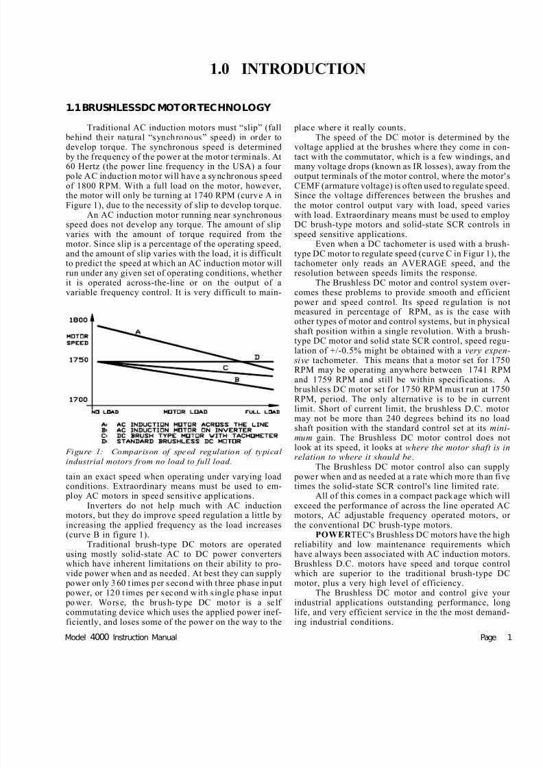
The switching of windings is controlled by a threechannel position encoder mounted on the motor shaft. Thehall effect transistors which are mounted on the feedback assembly are turned on and off by magnets in the encoder’s“xolox wheel”. These magnets are aligned with the mag-
nets on the rotor. The hall effect switches, which are non-contact (electrically isolated) devices, are mounted in posi-tions 60 degrees apart ( on a four-pole motor, they are 30degrees apart on an eight pole motor). It is not possible for the three switches to be all on or all off at the same time.There will always be two on and one off, or one on and twooff, at all times.
The speed of POWER TEC’s four pole brushless DCmotor is regulated by a two channel, 30 pulse (60 pole)digital tachometer on the motor shaft, which indicates bothspeed and direction of rotation. Eight pole motors (frames280 and larger, except over 2500 RPM) have 120 magnetic
poles around the outside of the xolox wheel. These polesalternately turn on and off two hall effect switches whichare connected to the control for speed control. There are twospeed feedback channels which are offset by 90 electricaldegrees, in quadrature.
These 30 pulse per revolution signals from the motor are electronically multiplied by 4 to supply a pulse every 3degrees of shaft rotation (larger motors use a 60 pulsetachometer, yielding 240 pulses per revolution, a pulse
every 1.5 degrees). Reference pulses are compared to pulsescoming back from the motor’s encoder. If the number of
pulses from the motor (the absolute number, not the fre-quency) do not equal the number of reference pulses ap-
plied, a position error count accumulates in an up/downcounter on the Speed Controller board. The number of accumulated pulses determines how much current is made
Figure 9: The encoder assembly - four magnet s
indicate position; outer magnets indicate speed
and direction.

7/29/2019 bldc motor operation control.pdf
http://slidepdf.com/reader/full/bldc-motor-operation-controlpdf 13/46
Page Model 4000 Instruction Manual
1.5 HOW TO USE THIS MANUAL
This manual is arranged into sections covering all ofthe stages of using the Model 4000:
1.0 Orientation to product.2.0 Specification3.0 Installation/Layout4.0 Wiring/Design5.0 Startup6.0 Troubleshooting7.0 Maintenance8.0 Performance options
Reading of the entire manual will assist in understanding of Brushless DC motors and controls. While thereare no schematic diagrams of the boards used in the Mode3500 in this manual, there are plenty of block diagrams andsimplified diagrams which will help the person using thismanual to observe and understand what is going on, and toisolate problems to the board level, if and when they shouldoccur.
If any questions about this manual arise, contact youdistributor, representative, or POWER TEC directly.
1.4 BRUSHLESS MOTOR BENEFITS
POWER TEC Industrial Corporation manufacturesBrushless DC motors and controls for the industrial envi-ronment. Other manufacturers produce brushless DC mo-tors for some specialized applications, but onlyPOWER TEC makes a full line of Brushless DC motors andcontrols from fractional to 600 Horsepower for use onindustrial power sources (230, 380, and 460 VAC three
phase) in standard NEMA (National Electrical Manufactur-ers Association) frame sizes at prices competitive withconventional DC and Adjustable Frequeny AC, includingvector.
Some important benefits of using POWER TEC Brush-less DC motors and controls are:
ABSOLUTE SPEED CONTROL REGARDLESSOF LOAD -- The speed regulation of the POWER TECBrushless DC motor and control system is 0%! The speedof the motor does not change from no load to full load.Options include a speed accuracy of 50 PPM (parts per million) and absolute ratio control.
INCREDIBLY HIGH EFFICIENCY -- The effi-ciency of the POWER TEC Brushless DC motor and con-trol exceeds that of either conventional DC or induction ACmotors and inverters. The Brushless DC motors are often insmaller frames than comparable motors. This efficiencycontributes to low cooling costs for rooms where BrushlessDC motors are installed as well.
VERY LOW MAINTENANCE -- The POWER TECBrushless DC motor is as rugged and reliable as the AC
induction motor. There are no brushes to change, no fieldsto burn up, and no commutator to be maintained. The bearings are long-life bearings, capable of years of opera-tion with only regular lubrication.
ABSOLUTE TRACKING -- Two motors can be setup to track pulse for pulse. Their shafts will be very nearlysynchronized. This capability is standard . Options includethe ability to operate at an absolute ratio from 0.0001 to7.9999.
The POWER TEC Brushless DC motor and control provide performance in their stan-dard configuration which exceeds the perfor-
mance of other types of motors and controls.Even when the other types of motors andcontrols are combined with expensive addedcost options, they do not perform as well as theBrushless DC motor and control do right out of the box.

7/29/2019 bldc motor operation control.pdf
http://slidepdf.com/reader/full/bldc-motor-operation-controlpdf 14/46

7/29/2019 bldc motor operation control.pdf
http://slidepdf.com/reader/full/bldc-motor-operation-controlpdf 15/46
Model 4000 Instruction Manual Page 9
2.1 ELECTRICAL RATINGS
LINE APPROX MAXIMUM MAXIMUM MAXIMUM TRIP * HP ** HALL
VOLTS LINE MOTOR HEAT HEAT CALIBRATE CALIBRATE SENSOR
VAC HORSE KILO CURRENT CURRENT OUTPUT IN RESISTOR RESISTOR STYLEPOWER WATTS AAC RMS AAC RMS WATTS BTU/HR OHMS OHMS CSLA1_ _
230 60 45 135 220 2450 8361 22 K 6.34 K DK 230 75 56 163 270 3030 10342 39 K 5.36 K DK
380 100 75 125 235 2675 9130 22 K 5.90 K DK 380 125 93 165 272 3150 10751 39 K 5.36 K DK
460 100 75 107 223 2041 6966 10 K 7.15 K DK 460 125 93 134 223 2551 8706 22 K 6.34 K DK 460 150 112 160 265 3062 10451 39 K 5.36 K DK
* Trip resistor is on Current Sensor board TB3 terminals 1 and 2; OPEN means no resistor is needed. All resistors are 1/4 watt, 1%
** HP calibration resistor is on Current Sensor board TB3 terminals 4 and 5; All resistors are 1/4 watt, 1% tolerance.Hall Sensor style refers to part number of Hall Effect Current Sensors. The number is on the sensor.
2.2 DIMENSIONS
Model 4000 chassis 39.00"H x 33.00"W x 13.00"D (991mmH x 838mmW x 330mmD)Weight = 242 lbs (110Kg)Model 4000 NEMA 1: 42.06"H x 36.06"W x 16.06"D (1068mmH x 916mmW x 408mmD Weight = 297 lbs (135Kg)Model 4000 NEMA 1A: 60.06"H x 36.06"W x 16.06"D (1524mmH x 914mmW x 406mmD)Weight = 325 lbs (147Kg)
Standard dimensions and weights do not include options.Nema 1 listed does NOT include space for options. Nema 1A has space for options.
2.3 ENVIRONMENTAL
ALTITUDE: Use above 3300 ft (1000 m) requires deratingAMBIENT TEMPERATURE:
Chassis 55°C (131°F) maximum NEMA 1 40°C (104°F) maximum
INPUT VOLTAGE TOLERANCE: +10%, -5% at all timesINPUT POWER FREQUENCY: 48 to 62 HertzRELATIVE HUMIDITY: 95% (non-condensing)SERVICE FACTOR: 1.0MAXIMUM SERVICE CAPACITY: 100 KVA (limited by input fuses AIC rating)STORAGE TEMPERATURE: -40°C to +65°C
2.4 PERFORMANCE
MAXIMUM LOAD: 125% for 1 minute out of 10 minutesSPEED REGULATION: 0% (no load to full load)SPEED ACCURACY:(percentages referred to set speed over 100:1 speed range)
2.0 SPECIFICATIONS

7/29/2019 bldc motor operation control.pdf
http://slidepdf.com/reader/full/bldc-motor-operation-controlpdf 16/46
Page 10 copyright 1993, 1994 by POWER TECIndustrial Corporation Used by permission
Analog Mode: +/- 1.0% (typical with speed pot supplied by internal reference)linearity: +/- 0.5% (typical from external reference source)Digital Mode: 0% (+/- 3/4 revolution of motor shaft)
DISPLACEMENT POWER FACTOR: 0.96
2.5 CUSTOMER ADJUSTMENTS
ACCELERATION TIME: 2 to 30 seconds, linear, analog modeDECELERATION TIME 2 to 30 seconds, linear, analog modeMAXIMUM SPEED: 600 to 5000 RPM, motor dependentJOG SPEED: 0 to 30% of maximum speed, analog mode onlyCURRENT LIMIT: 0 to 150%, resistor calibratedGAIN RANGE: 10 to 1STABILITY: 20 to 1 dynamic rangeMINIMUM SPEED: 0 to 15% (with 5K speed pot)JUMPERS JP1 IN: ramp to stop OUT: coast to stop
JP2 IN: standard accel and decel OUT: 50 millisecond accel and decel
2.6 INDICATORS
Current Controller board Speed Controller board Current Sensor boardHS1, HS2, HS3 (encoder) RUN Under Voltage
Low level POWER Current Limit Undervoltage Time OutOVervoltage/UNdervoltage Zero S peed Over VoltagePower Loss Heatsink Over TemperatureInstantaneous Over Current THer MaLBUSS (charging/ready) Base Driver board RELAY ONENABLE Base Drivers (6)
2.7 TERMINAL DESCRIPTIONS
TB1 Current Controller Board (141-108)
1 Shields and Ground connection
2 HS1 position encoder
3 HS3 position encoder
4 HS2 position encoder
5 HS4 speed encoder
6 HS5 speed encoder
7 Common for encoder ONLY
8 +5 VDC for encoder ONLY
9 Common for terminals 10 and 11
10 Auto/Manual Selection +24 VDC
11 External Frequency Input +24 VDC
12 Collector of FAULT transistor
13 Emitter of FAULT transistor
14 Load output (-2VDC = 150%)
15 Auxiliary Supply output
16 Power Common
TB2 Speed Controller Board (141-107)
1 RUN contact (closes on RUN)
2 RUN contact 1 Amp 125 VAC
3 -24 VDC raw supply 50 mA max4 RUN input +24VDC to RUN5 RUN hold (junction of RUN and STOP)6 SPARE (tie point for motor thermal7 Emergency STOP +24VDC to RUN8 +24 VDC RUN Logic Supply 50 mA max
9 +10 VDC reference supply10 Speed reference input 0 to +10VDC11 Minimum speed connection for speed pot12 Signal common13 Jog input +24VDC to JOG14 Forward/Reverse input +24VDC to reverse15 Frequency output open collector to common16 Zero speed output open collector to common17 +24VDC raw supply 50 mA max
18 Current reference 0 to +10VDC (velocity error)
TB3Current Sensor Board (144-9)1 Trip calibration resistor
2 Trip Calibration resistor
3 RTO output
4 Horsepower calibration resistor
5 Horsepower calibration resistor
6 Motor Thermal input
7 Motor Load output (-10VDC = 180%)
8 Common9 -24 VDC
10 Contactor control

7/29/2019 bldc motor operation control.pdf
http://slidepdf.com/reader/full/bldc-motor-operation-controlpdf 17/46
Model 4000 Instruction Manual Page 11
3.1 RECEIVING
POWER TEC products are packed carefully for ship-ment, but occasionly damage may occur between the factoryand the site at which the equipment will be installed. When the
equipment is first received, a physical inspection should bemade of the shipment to determine if there is any visible physical damage which may have occurred in shipping. If inspection is put off until later, damage discovered may delayinstallation.
If damage is found, notify the carrier of the equipmentimmediately. Equipment is shipped F.O.B. the factory. Ship-
ping claims must be filed by the receiver directly to the carrier.POWER TEC will assist claims with information necessary toassess and repair damage.
In unpacking, be sure to remove all packing materials,since materials left in the control or motor may interfere withair flow necessary to cool the equipment.
DO NOT THROW AWAY THE MANUALS, CONNEC-TION DIAGRAMS, OR OTHER INFORMATION SENT INTHE SHIPPING CONTAINER
3.2 BEFORE INSTALLATION
Improper lifting practices can cause serious personalinjury. Use proper equipment to move materials.
DANGEROUSLY HIGH VOLTAGES ARE NORMAL INTHIS EQUIPMENT! WHEN POWER IS REMOVED, THECAPACITORS ARE NOT DISCHARGED AT ONCE! BESURE THE INPUTPOWER IS OFF
AND THE CAPACI-TORS ARE DIS-CHARGED BE-FORE WORKINGON THE MOTOR OR THE MOTOR CONTROL.
POWER TEC'sModel 4000 has beencompletely tested atthe factory and is builtto standards appliedto all POWER TEC's
other drives.This test-ing is done to ensuresafety of the basicunit. It is the respon-sibility of the user of this equipment to en-sure that the installa-
tion complies with all other national, state, and local codeswhich apply to this equipment and to the installation. Thisapplies to grounding of the motor, motor control chassis and
enclosures as well.
The use of external circuitry or devices and peripheraequipment not supplied by POWER TEC as a part of theequipment, or equipment which is supplied separately byPOWER TEC for wiring by the customer at the user's requestis done entirely at the user’s risk.
DO NOT DISCONNECT, UNPLUG, OR REMOVE ANY CONNEC-
TIONS ON THE MOTOR OR ON THE MOTOR CONTROL
WHILE POWER IS APPLIED. SEVERE DAMAGE AND/OR
PERSONAL INJURY MAY RESULT FROM THESE ACTIONS
THE USE OF TEST EQUIPMENT ON THE MOTOR AND
CONTROL IS VERY HAZARDOUS. THIS EQUIPMENTSHOULD BE SERVICED ONLY BY PERSONNEL EXPERIENCED IN THE SERVICING AND MAINTENANCE OFHIGH POWER ELECTRONIC EQUIPMENT! USE THEPROPER TEST EQUIPMENT AND PROCEDURES!
Do not use a megger on the electronic equipment with-out consulting the factory. If a megger is used on the motor orthe wiring to the motor, disconnect the wiring from the controlDO NOT USE A MEGGER ON THE MOTOR ENCODERCABLE AT ANY TIME!
Figure 11: The mounting dimensions of the chassis version of Model 4000.
3.0 PHYSICAL INSTALLATION

7/29/2019 bldc motor operation control.pdf
http://slidepdf.com/reader/full/bldc-motor-operation-controlpdf 18/46
Page 12 copyright 1993, 1994 by POWER TECIndustrial Corporation Used by permission
promote air flow through the heatsink. Avoid mounting onechassis directly above another too closely with the result thathot air from the lower chassis flows directly up into the other chassis.
The NEMA 1 enclosure should be mounted vertically inan area which allows a free flow of air around the enclosure andsome air flow around the back. Maximum ambient tempera-
ture of the air surrounding the NEMA 1 control should notexceed 40°C (104°F).
There must be at least 6" (150 mm) of free air space inall directions around the NEMA 1 enclosure. If there are twounits mounted directly in line vertically, there should be atleast 12" (300 mm) between the units.
The size of the enclosure for the chassis units is deter-mined by the total heat dissipation within the enclosure. Theheat output of the controls is given in section 2.1 on page 9.Enclosures which use air flow for cooling (NEMA 1, 1A, and
NEMA 12 ventilated) must have an air flow of 1 CFM (cubicfeet per minute) for each 10 watts of dissipation (1 cubic meter /minute for each 350 watts).
Totally enclosed units (NEMA 3,4, or 12) must allow 1
square foot of enclosure surface area (including front, sides,top and bottom surface areas) for each 7 watts of dissipation(75 watts per square meter).
For further information, consult POWER TEC's publi-cation "THERMAL MANAGEMENT".
3.3 INSTALLATION
Figure 11 gives the basic dimensions of the 4000 chas-sis. The basic dimensions of the NEMA 1 version of the Model4000 are shown in figure 12.
When mounting the chassis in an enclosure, care should be exercised to avoid handling the chassis by parts which may
bend or come loose. This especially applies to the plexiglasscover of the unit. Try to support the chassis as much as
possible by the outside edges of the heatsink.
WARNING! : IF THE CHASSIS HAS BEEN BENCH TESTED PRIOR TO INSTALLATION, CHECK TOMAKE SURE THAT THE BUSS CAPACITORS HAVEFULLY DISCHARGED BEFORE ATTEMPTING TOINSTALL THE CHASSIS.
3.4 THERMAL CONSIDERATIONS
The 4000 chassis may be mounted in a vertical position(fuses up) in a suitable enclosure. The Model 4000 may also be
mounted "sideways" with the fans on the bottom. The ambienttemperature of the air immediately surrounding the chassismay not exceed 55 degrees C (131 degrees F).
When the chassis is installed in an enclosure there must be at least 9" (150 mm) of free space on each side of thechassis, this space allowed for the proper air flow through theheatsink fans. The chassis must be mounted vertically to
Figure 12: Physical dimensions of the NEMA 1 version of the POWERTEC Model 4000.

7/29/2019 bldc motor operation control.pdf
http://slidepdf.com/reader/full/bldc-motor-operation-controlpdf 19/46
Model 4000 Instruction Manual Page 13
After manufacturing and testing, the most im-
portant time in the useful life of a motor or motor
control is the installation process. Decisions are
made, or not made, on all of the considerations which
are to be involved in the environment in which the
motor and control will spend their operational life.
Issues ignored during installation are sure to crop up
at a later time, and the time and manner in which they
crop up may be very inconvenient and/or very pain-
ful, not to mention very costly.
4.1 GENERAL REQUIREMENTS
POWER TEC motors and controls require no more careand concern in the installation than any other precise motor and control, although they do require more consideration of the environment than run-of-the-mill motors and controlswhich do no more than run a motor, period. If superior
performance is expected, then it is normal to expect superior care in installation.
One of the most frequent problems encountered withdigital type equipment is electrical noise. Noise is an insidious
problem which is capable of causing not only destructive problems, but also intermittent, annoying problems. The meth-ods used in the installation of the equipment plays a large partin prevention of electrical noise interference in the operation.
Any digital type control requires that extra care be taken inthe grounding of the equipment, the shielding of wires andcables and placement of wires in the conduit runs. Payattention to the sections which address the precautions againstnoise, whether in the control, in the motor, in the wiring, or inany auxiliary equipment. Follow the directions of other manu-facturers for other equipment that come with the other equip-ment to be used in the system.
4.2 POWER SUPPLY
The POWER TEC Model 4000 Brushless DC motor controls requires a source of three phase input power with a
KVA rating at least equal to its horsepower rating. The branchservice rating (in KVA) supplying the control should not bemore than 10 times the rating of the control, or specialdisconnecting means ratings or sizes may be required.
An ISOLATION TRANSFORMER is not necessary for the operation of the POWER TEC Brushless DC motor con-trol, but, if it is desired to use one, or if one is required by localcode requirements, it should be sized (in KVA) at least as largeas the horsepower rating of the motor control.
The fuses which are supplied on the input of the Mode
4000 Brushless DC motor control are designed to protect thesemiconductor elements of the unit. THEY MAY OR MAY
NOT MEET THE REQUIREMENTS OF NATIONALSTATE AND/OR LOCAL CODES.
The responsibility for meeting the branch serviceprotection and other code requirements of nationalstate and local codes belongs to the user.
Since POWER TEC controls are supplied without inputdisconnects, the user must supply a disconnecting meanswhich meets applicable code requirements. The maximuminterrupting capacity (AIC) of the fuses on the input of theModel 4000 is 200,000 amperes. If the maximum short circuit
current available on the service is greater than this, a disconnect with an AIC rating greater than 200,000 amperes will berequired.
Wire sizes for the input of the control may be determined by the fuse sizes on the control. The output current of aBrushless DC motor control is always greater than the inputcurrent. Check the nameplate of the control for input currentrequirements and output current limitations. Check the motornameplate for its required current.
NOTICE: THE INPUT CURRENT OF THEBRUSHLESS DC MOTOR CONTROL IS NOT REP-RESENTATIVE OF THE LOAD CURRENT ONTHE MOTOR! The input current is representative of
the POWER output of the motor. The only point atwhich the input AC line current reaches its full valueis when the motor is operating at full speed with fulload. DO NOT ATTEMPT TO MEASURE MOTORLOAD BY MEASURING THE AC INPUT LINE CUR-RENT TO THE BRUSHLESS DC MOTOR CONTROL
The tolerance of the input voltage to the Brushless DCmotor control Model 4000 is plus ten percent (+10%) to minusfive percent (-5%) of the nominal voltage listed on the name
plate of the control. Measuring the voltage at the input to thecontrol when the control is off neglects the effects of load onthe power source. The actual input voltage to the controshould be measured while the control is operating the motor in
a loaded condition.Transient power line disturbances of a minor nature wil
not normally disturb the motor controls. There is a built inability to "coast through" an interruption of AC power of op to80 milliseconds. Nor does the Model 3500 generate significannoise back onto its power service.
Any effects which tend to distort the AC waveform mayhowever, be detected as an under-voltage or phase loss condi-tion. Some types of motor controls with diode front ends may
4.0 ELECTRICAL INSTALLATION

7/29/2019 bldc motor operation control.pdf
http://slidepdf.com/reader/full/bldc-motor-operation-controlpdf 20/46
Page 14 copyright 1993, 1994 by POWER TECIndustrial Corporation Used by permission
Figure 13: Standard connections for the POWERTEC Model 4000.

7/29/2019 bldc motor operation control.pdf
http://slidepdf.com/reader/full/bldc-motor-operation-controlpdf 21/46
Model 4000 Instruction Manual Page 15
tend to flatten the peak of the AC sine wave, causing the peak voltage to be significantly less than it should be. This is usuallycaused by a service which is not stiff enough to supply theconnected capacity or by external line impedances whichcause excessive voltage drops in the feeders.
A service which supplies the Model 4000 as well as ACmotors must be capable of supporting the starting current of the motors without dropping more than 5%.
The power source also must be capable of supporting acurrent limit condition for short periods without pulling downthe input voltage below the low voltage threshold. Otherwisetrips will occur.
4.3 CONNECTING THE MOTOR
4.3.1 Motor LeadsA wiring card for STANDARD CONNECTIONS is
supplied with every drive shipped from the factory. It showshow to connect the Brushless DC motor to the motor control.
It is vitally important that the connections to the motor be made properly. Figure 13 on page 14 is a reproduction of theconnection card. Figure 14 is a drawing of the power input fuseand motor output connection area of the Model 4000, showingthe location of the other fuses.
The wires to T1, T2, and T3 on the control must beconnected to the corresponding connections of the motor. If these wires are not in the proper order, the motor will notoperate. If any of these connections should open up, the motor
will run erratically, if at all. The motor leads marked T1, T2and T3 will always connect to T1, T2, and T3 on the controlalthough the other motor wires connected with T1, T2, and T3at the motor will vary with the connection of the motorwindings.There may be other wires connected to T1, T2 andT3 at the control, such as Dynamic Braking wiring, if the DB
option is installed.
4.3.2 Motor GroundA ground connection may be picked up at any bolt or
screw in the motor junction box, and this ground connectionneeds to be run to the control with the motor power wires andconnected to the same ground as the control’s ground. Thecontrol ground must be connected to earth ground as close as
possible to the power ground.
THIS GROUND WIRE MUST BE RUNIN ADDITION TO THE GROUNDING OFTHE MOTOR FRAME TO ITS MOUNTING
The purpose of this separate ground is to equalize the potential between the motor's frame and the control chassisThough the motor may be grounded to its mounting frame, andthe frame may be connected to a ground, there may be enoughimpedance between the motor and the control chassis to
broadcast EMI and RFI. A direct wire connection between themotor frame and the drive chassis will minimize the effects oRFI and EMI.
Figure 14: Input power fuses and output connections of the Model 4000. .

7/29/2019 bldc motor operation control.pdf
http://slidepdf.com/reader/full/bldc-motor-operation-controlpdf 22/46
Page 16 copyright 1993, 1994 by POWER TECIndustrial Corporation Used by permission
4.3.3 Output Contactor
If an output contactor is used with the Model 4000 motor control, provisions MUST be made in the control circuits tointerlock the output contactor with the Emergency Stop cir-cuits. If the output contactor is not properly interlockedwith the motor control, damage to the motor control WILL
result.The requirements are:1. The contactor must close the main power contacts
BEFORE the drive is enabled; AND2. The contactor may only open its contacts AFTER
the drive is disabled.3. The contactor must be able to carry the rated motor
current, but is not required to make or break higher levels of current, as AC motors must do.
Figure 15 shows the plan for connections for using aseparately powered output contactor (which is available fromPOWER TEC) with the Model 4000 control. In this configu-ration, the contactor will energize when there is a run com-mand and de-energize ONLY on an emergency stop. The
contactor will stay energized during normal stops.POWER TEC makes available a track mount PC board
(Part # 156-012) with the circuitry shown for sequencing of output contactors and dynamic braking contactors..
DO NOT break the ground connection or the cableconnections with the output contactor.
It is strongly recommended that a maintained type of Emergency Stop button (twist or pull to release) be used in anyEmergency Stop system.
ALWAYS BE SURE THAT EMERGENCY STOP HASBEEN ACTIVATED BEFORE GOING NEAR DRIVENEQUIPMENT USING AN OUTPUT CONTACTOR CON-
NECTED AS SHOWN.
4.3.4 Motor Feedback Cable
The encoder feedback cable must be a shielded cable.See figure 8 on page 14 for shield connections at the motor end.The shield is connected to TB1 terminal 1 on the control end.Standard installation calls for a nine conductor shielded cable(Belden part #9539 or equivalent). The colors of this cable
correspond to the colors of the wires in the motor and on theconnection diagram. The Purple and White wires may beinterchanged without ill effect. Likewise, the connections onTB5 terminals 1 and 3 may be reversed without difficulty.
If the motor thermal protector is to be used in a 120 VACcircuit, it should be run in wiring outside of the cable, andseven conductor shielded cable may be used. In this case, if thecable wire colors are different from the diagram, they need to
be checked carefully to be sure that the proper connections aremade. Also the shield must be continuous all the way from themotor to the control. (Do NOT ground the shield at intermedi-ate points). This applies to all junction boxes which may beinstalled between the motor and control.
DO NOT USE THE SHIELD OF THE ENCODER CABLE AS AN ACTIVE CONDUCTOR !
4.4 CONTROL CONNECTIONS
The control circuits of the POWER TEC Brushless DCmotor controls operate on 48 VDC. This voltage is derivedfrom the raw +24 VDC (with respect to common) and the raw-24 VDC supplies. Using 48VDC tends to balance the load of relays and other devices on the supplies instead of placing the
burden on one of the supplies, and requires less operatingcurrent than 24 VDC devices.
Some of the relays used with the Model 4000 must be
24VDC when used with open collector functions (see section4.6). The maximum current from each of the raw supplies is 50milliamps. Due to this supply limitation, when several 24VDC external relays are used, they should be externally
powered from a separate supply..THE POWER SUPPLIES OF THE MODEL 4000
SHOULD NOT BE USED FOR EXTERNAL EQUIPMENT!POWER TEC has an optional power supply (part # 127-101)available to supply additional power.
It is possible to operate the control circuits with a varietyof devices. Standard operator devices may be used, but thecurrent flowing through these devices is very small. Whencontrol push-button and other operators are to be located morethan 30 feet away from the motor control, the use of 120 VACcontrol circuits should be considered. The 120 VAC relaysmust be run by a customer supplied transformer, and normallyopen and normally closed contacts substituted for the nor-mally open and normally closed contacts shown in the connec-tion diagram (figure 13). Take note in the last section of the useof 120 VAC on the motor thermal.
Figure 15: Connecting an output contactor wi th an
externally powered coil to a Model 4000.

7/29/2019 bldc motor operation control.pdf
http://slidepdf.com/reader/full/bldc-motor-operation-controlpdf 23/46
Model 4000 Instruction Manual Page 17
EMERGENCYSTOP
TB2-7 and TB2-6 ** Must be closed to RUN. Enables RUN circuits on closing.
On opening, disables all control functions immediately.
DO NOT JUMPER THESE TERMINALS, especially if
the RAMP STOP jumper is installed!
MOTOR THERMAL
TB2-8 and TB2-6 ** Normally closed thermal switch in the motor.. Acts likeE. Stop on opening if the control circuits are wired in the
standard configuration shown in figure 14. THE MOTOR
THERMAL SWITCH MUST BE CONNECTED IN
ORDER TO PROTECT THE MOTOR PROPERLY!.
RAMP STOP TB2-7 and TB2-5 Must be closed to run. On opening, drive will ramp to
zero speed if RAMP STOP jumper is installed and control
is in analog mode. Otherwise, motor will coast to a stop.
In digital mode frequency input must be reduced to zero.
RUN TB2-5 and TB2-4 Momentary close to run. Must be open if momentary
STOP is used to terminal 5. RUN relay CR latches
between the terminals if terminal 5 is energized. Must be
held closed if two-wire connection is used (4 and 7).
RUNCONTACT
TB2-1 and TB2-2 Closes when terminal 4 is energized. Stays closed as long
as relay CR is maintained by RAMP STOP button on
terminal 5, or two-wire connection maintains connection
on terminal 4. DOES NOT OPEN ON FAULT!
ZERO SPEED TB2-16 and TB2-12 Open collector transistor, C on 16, E on 12. Rated at 50
mA @ 50VDC. Turns on above 10 RPM and off below
10 RPM. May chatter at very low speeds.
JOG TB2-5 and TB2-13 Starts control in JOG mode (no latching). The control
operates while JOG circuit is closed. Speed set by pot on
board if in analog mode, otherwise frequency must be
supplied. JOG OVERRIDES RUN!
REVERSE TB2-8 and TB2-14 Close in analog mode to cause motor to go to zero speed
and return to set speed in the opposite direction. Open to
do same thing in opposite direction. May be applied at
any speed. Does not work in digital mode unless input
frequency is reduced to zero..
FAULTOUTPUT
TB1-12 and TB1-13 Isolated opticoupler transistor, C on 12, E on 13. Rated at
50 mA @ 80 VDC. Turns on when buss is at proper level.
Turns off on trip condition.
ANALOG /DIGITAL
SWITCH
TB1-10 and TB1-9 Apply +24 VDC at terminal 10 with respect to terminal 9
to change from analog to digital mode. Frequency must be
applied at terminal 11 with respect to terminal 9.
** NOTE: TB2 terminal 6 is a "dead" terminal which has no connection on the board and is used as a tie point.
Table 1: Control circuit connections for the Model 4000.
7/29/2019 bldc motor operation control.pdf
http://slidepdf.com/reader/full/bldc-motor-operation-controlpdf 24/46
Page 18 copyright 1993, 1994 by POWER TECIndustrial Corporation Used by permission
Table I is an explanation of the connection and functionof the control circuits of the Brushless DC motor control. Readthe descriptions of the operations of the circuits carefully,since there are some differences between the operations in theanalog and digital modes.
In some installations there is a temptation to place a jumper across Emergency Stop terminals, rather than to install
ESTOP buttons. This could set up an UNSAFE situation. IT ISSTRONGLY RECOMMENDED THAT THE EMER-GENCY STOP BUTTON (or ESTOP relay) BE IN-STALLED ON THE 4000! They have a ramp stop functionwhich causes the motor control to decelerate the motor (in theanalog mode) to zero speed before shutting off. (In digitalmode, the external frequency must be reduced to zero for thisfunction.) Even if the RAMP STOP jumper is removed in a
particular installation, a replacement board or control may be put in at a later date with the jumper installed, creating a safety problem. If the control does not stop when the RAMP STOPis pushed, for any reason, the Emergency Stop is the only wayto stop it, short of removing power from the control.
The motor thermal must be used to adequately protect
the motor from overheating. The motor thermal on thePOWER TEC Brushless DC motor is able to protect the motor
because it is located where the heat is produced in the motor,in then stator windings. Very little heat is produced in the rotor of the Brushless DC motor.
Many of the control functions are changed slightly whenthe drive is changed from the analog to the digital mode. Theanalog mode uses the analog reference input (TB2 terminal 10)to set speed. In digital mode they look for an external fre-quency at TB1 terminals 11 and 9 (see section 4.5), and ignorethe level of the analog input. It always looks at TB2 terminal14 for the direction of rotation (forward or reverse).
The use of "two wire" control between terminals 7 and4 on TB2 DOES NOT disable the RAMP STOP function. The
only way to disable the RAMP STOP function is to remove theRAMP STOP jumper.
The RAMP STOP function in the analog mode shorts theanalog reference input to zero, causing the motor to decelerateto zero speed before shutting off. In digital mode, the externalfrequency must be reduced to zero for the RAMP STOP tofunction. POWER TEC's DIGIMAX IV takes care of thisfunction when it is installed according to standard connections(see page 38), but in other configurations the system designer must make sure that the frequency goes to zero. The externalfrequency may simply be taken away (such as by the openinga relay contact), in which case the motor will coast to zerospeed and then the control will shut off.
The zero speed output may "chatter" at low speeds, particularly when the motor is unloaded. This may be over-come by using the zero speed relay as a holding contact (seesection 4.6)
Note that the JOG function OVERRIDES the RUNfunction. If the JOG input (+24 VDC at terminal 13 is activatedwhile the in the RUN mode, it will be ignored.
In analog mode, the JOG speed is set by the on board pot(acceleration in current limit), but in digital mode the speed isset by the external frequency (see section 5.1.7 for settingmotor direction in Jog). RAMP STOP is active during the JOGmode, but deceleration time will be determined by the "coasttime", since the speed signal from the on board JOG potenti-ometer bypasses the accel/decel circuits. In digital mode, the
accel rates is set by the rate of change of the externalfrequency, or current limit, if the rate is too fast. The decel ratein digital mode will be determined by the "coast time" (seesection 1-2) if it is longer than the decel time set.
4.5 REFERENCE OPTIONS
There are options available for speed control of thePOWER TEC Models 4000 Brushless DC motor control.They break down into two types: ANALOG and DIGITAL.Both types are contained in the basic control. The selection ismade by the application of +24 VDC at TB1 terminal 11 withrespect to TB1 terminal 9. This is an optically coupled input
which is not referenced to the control common.
4.5.1 Analog reference
Analog speed control is the most common type used for motors and controls. The Model 4000 has a positive 10 VDCspeed references built in. The reference source is accuratewithin 1%.
The analog control of speed consists of supplying a 0VDC (for zero speed) to +10 VDC for full speed forward or reverse. Directional selection is made at TB2 terminal 14.
This analog signal is applied to TB2 terminal 10 withrespect to TB2 terminal 12, which is the signal common of themotor control.
This analog signal might come from a speed potentiom-eter which is connected to include the use of the minimumspeed potentiometer on the Speed Controller board:
High side of potTB2 terminal 9 (+10 VDC source)
Wiper of potTB2 terminal 10 (reference input)
Low side of potTB2 terminal 11 (common)
The speed potentiometer may also be connected for operation without a minimum speed adjustment:
High side of potTB2 terminal 9 (+10 VDC source)
Wiper of potTB2 terminal 10 (reference input)
Low side of potTB2 terminal 12 (common)

7/29/2019 bldc motor operation control.pdf
http://slidepdf.com/reader/full/bldc-motor-operation-controlpdf 25/46
Model 4000 Instruction Manual Page 19
Of course, in the analog speed mode, any 0 to +10 VDCreference signal will act as a speed command as long as it isreferenced to TB2 terminal 12, and the direction of rotationwill depend upon the polarity of the voltage at TB2 terminal 14with respect to TB2 terminal 12 in the analog speed mode.
Input voltages greater than +10.6 VDC or -0.6 VDC areclamped by the input circuits. Nominal input impedance for
voltages less than +10VDC is 50Kohms. Potentiometers usedfor speed pots should be no less than 2 Kohm (reference supplylimitation, and not greater than 10K. Above 10 Kohms the potis non-linear, so a setting of 50% may give a speed of 47%.This is especially true with multi-turn potentiometers, whennon-linearity is made most noticeable by the dial reading.
When a manual speed potentiometer which is supplied by TB2 terminal 9 is used, the speed accuracy (versus refer-ence) of the control will be dependent on the stability of thereference source and temperature and noise effects. This isgenerally better than 1% after the drive and motor havereached their operating temperatures.
If an external reference source is used, the control willtrack the input voltage at TB2 terminal 10 within +/- 0.5%.
The tolerances of analog circuitry determine how well thecontrol will do with an analog reference. While the abovenumbers represent the worst cases, typical speed accuracy
performance in a load and temperature stabilized system can be expected to be better than 0.1% of setpoint.
In analog mode of operation, maximum motor speed inrelation to the applied reference is determined by adjustmentof the MAX SPEED potentiometer on the Speed Controller.This pot calibrates the motor speed for the applied reference.The brushless DC motor, by itself, will not exceed its basespeed by very much when it is heavily loaded. It is possiblethat, if the MAX SPEED pot is turned up too far, and the loadis light, it will seem to have no effect. The maximum speed of the motor will not be attained until the motor has reached
operating temperature. Like any NEMA standard DC motor,a warm-up time is necessary to reach operating temperature,due to the fact that a cold motor develops more CEMF (andtherefore more torque). The MAX SPEED adjustment has noeffect in digital mode.
The on-board JOG pot is analog. It is activated by theJOG circuit, which overrides the RUN circuits. The on boardJOG pot does not determine the JOG speed while the controlis operating in the DIGITAL MODE.
It is not necessary to reduce the input reference to zero before starting or stopping the drive. The reference inputcircuits and the accel/decel circuits are clamped while thecontrol is stopped. The clamp is released when the RUN isactivated. The clamp is turned on also for the RAMP STOPfunction. The speed pot may be left at its speed setting, or anexternal reference may be left connected while the control isdecelerating during the RAMP STOP function, or while thecontrol is stopped. When RUN is restored, the control willaccelerate at the Accel rate.
4.5.2 Digital Reference:
Since the Brushless DC motor control system is inherently digital, the performance in the digital mode of operationfar exceeds the performance in the analog mode. In the digitamode the control and motor respond to a frequency signawhich is fed to the control from an external source.
In the digital mode the same digital control circuitry isused for the speed control as is used in the analog mode. Theanalog output of the accel/decel circuits drives a voltage-controlled-oscillator (VCO), which in turn feeds the digital
circuitry. In digital mode the VCO is bypassed and an externareference frequency is used to control speed.
The digital mode is activated by applying a nominal +24VDC voltage to TB1 terminal 10, positive with respect to TB1terminal 9 (figure 16). There is also a jumper next to P2 on theCurrent Controller board (141-108) which, when placed in theAF position of the jumper, switches the control into the digitamode without energizing terminal 10 with an external voltage(see figure 32 on page 33).
Either of these actions disconnects the control's internaVCO and looks for a frequency at TB1 terminal 11, which mus
be positive with respect to TB1 terminal 9. This frequencysignal must meet certain specifications:
“ON” VOLTAGE: 18 VDC min, 30 VDC max“OFF” VOLTAGE: less than 1.5 VDCFREQUENCY: 2X desired RPM (250 frames orsmaller)DUTY CYCLE: 25% min, 75% maxMAXIMUM FREQ: 50 KiloHertz
The best tracking is gained by “ramping” the frequencychanging the frequency gradually. If a frequency is presenwhen the control is turned on, the motor accelerates in currenlimit. The nature of the Brushless DC motor control is that themotor must return a pulse for each reference pulse suppliedexcept in current limit! If the control goes into current limit
pulses will be lost. So it is best to not change the externafrequency so rapidly that the motor cannot respond withoutgoing into current limit.
Figure 16: Analog/digital switch and frequency inpu
circuits of the POWER TEC Brushless DC motor control

7/29/2019 bldc motor operation control.pdf
http://slidepdf.com/reader/full/bldc-motor-operation-controlpdf 26/46

7/29/2019 bldc motor operation control.pdf
http://slidepdf.com/reader/full/bldc-motor-operation-controlpdf 27/46
Model 4000 Instruction Manual Page 21
FAULT RELAY
A 48 VDC relay may be connected to the POWER TEC brushless DC motor control in the manner shown in Figure 20.
Using an auxiliary relay makes fault contacts available to 120VAC control circuits (the fault output of the board is the outputtransistor portion of an optical coupler, and the optical coupler can only operate direct current circuits up to 50 VDC at 50milliamps). The diode around the coil of the fault relay isnecessary for surge protection.
The fault circuits are designed to be fail safe. If there isno fault, the relay is energized. If the relay should fail for anyreason, the relay will be off, indicating a fault.
ENABLE RELAY
On the POWER TEC Model 4000 there is a way toobtain an enable relay output which combines the functionaeffect of the RUN and the FAULT relays.
The RUN relay is pulled in by the application of +24VDC to TB2 terminal 4. The RUN relay will stay on as long
as there is a sufficiently positive voltage on that terminal. TheRUN relay does not drop out when a trip occurs. It only dropsout when both terminals 4 and 5 on TB2 are open.
The FAULT relay pulls in when there are no faults (i.e.when the buss is charged up after application of power, or, aftera previous fault is reset by pressing the STOP button). It onlydrops out after a trip occurs.
Neither the RUN nor the fault tells the user by itself thathe control is actually in an operational state, but the combination of the two, when both are ON, says that the control is onand that there are no faults. This circuitry will shut off whenthe RUN circuit is dropped, even if the control is deceleratingin RAMP STOP.
Figure 21 illustrates the wiring and connections to
connect an ENABLE relay to the drive. The maximum currenis 50 mA. The diode around the coil must be installed.
ZERO SPEED RELAY
A 24 VDC relay may be connected from the +24 VDCunswitched supply to the zero speed output terminal TB2terminal 1 (see Figure 22).
The zero speed output is an open collector transistorwith the collector connected to TB2 terminal 1 and the emitterto control common. The Zero Speed relay may be used toindicate that the motor is actually running.
The relay coil current must be limited to a maximum of50 milliamps. The diode around the relay coil must beinstalled to prevent any high voltage transients at turn-off from
Figure 20: Adding a FAULT relay.
Figure 21: Obtaining an ENABLE indication.
Figure 22: Connecting a ZERO SPEED re lay. Note tha
the relay coil is 24VDC, so current should be kept low.

7/29/2019 bldc motor operation control.pdf
http://slidepdf.com/reader/full/bldc-motor-operation-controlpdf 28/46
Page 22 copyright 1993, 1994 by POWER TECIndustrial Corporation Used by permission
damaging the transistor or the power supply of the control. DO NOT USE THE ZERO SPEED RELAY CONNECTIONSHOWN IN FIGURE 22 WITHOUT CONNECTING THEDIODE AS SHOWN.
The relay turns on when the motor is turning more than10 RPM and stays on until the motor is no longer turning faster than 10 RPM. There is a small hysteresis built in.
The zero speed output is useful for determining if themotor is actually running. The pulses which control the zerospeed output come directly from the motor. It is not necessaryto use an external zero speed circuit to shut off the Model 4000.There is a built in RAMP STOP function. However, it issometimes necessary to detect zero speed in a system.
On light loads at very low speed, the motor speed maychange enough to cause the zero speed relay to “chatter”,especially with high gain or an incorrect STABILITY adjust-ment. This is caused by the rapid accumulation and dischargeof pulses in the counting circuits which determine zero speed.Chatter does not affect the internal RAMP STOP function. Thechatter is most likely to occur at low speeds and when thingsare happening quickly. As the load increases on the motor, the
amount of chatter will be less.The chatter may
be overcome by usingthe zero speed outputto indirectly control anexternal relay whichwill perform the zerospeed function, shut-ting off the first timethe zero speed relayopens up and requir-ing some other signal
to turn on again. A typical circuit is shown in figure 23.
4.7 PLC INTERFACE
The interface of the Model 3500 with a process control-ler is dependent upon the ability of the PC to handle therequired signals. Most of the signals are +24 VDC or +24 VDCand -24 VDC for control, or +10 VDC for speed. Computer
Figure 23: A circuit to eliminate
chatter on the zero speed relay.
generated frequency signals may also be used for speed (seesection 4.5.2 and figures 16 and 17).
Figure 24 illustrates the method for using an opencollector output to “sink” the input of a +24 VDC PC inputmodule. There are two types of input modules. A “sourcing”
connection supplies voltage from the input source, but in the
“sinking” connection, voltage supplied by the module andconnected (sunk) to common by the connected input device.Figure 25 shows a sourcing connection.
Connections similar to those in figures 24 and 25 may bemade to a PLC input module with the FAULT output of thecontrol at TB1 terminals 12 and 13 to sense a FAULT in thedrive. This is illustrated in figure 26. Remember that theFAULT output transistor is “ON” when there is no fault
present in the control. This means a positive level at terminal12 is a fault indication.
It is recommended that all operation of the controlcircuits of the Model 4000 be done with relays. These circuitssee 24VDC to ground, but they operate at 48VDC . RUN, JOG,STOP and EMERGENCY STOP operate on +24 VDC sup-
plies, but the circuitry is connected between positive andnegative supplies, and it is difficult to make connections whichdo not involve both power supplies.
Figure 24: SINKING connection to a PLC.
Figure 26: Connecting FAULT output to a PLC.
Figure 25: SOURCING connect ion to a PLC.

7/29/2019 bldc motor operation control.pdf
http://slidepdf.com/reader/full/bldc-motor-operation-controlpdf 29/46
Model 4000 Instruction Manual Page 2
5.0 OPERATION
Figure 27: Connections for using or not us ing a minimum
speed pot with the Model 4000.
5.1 ANALOG INPUT OPERATION
The POWER TEC Brushless DC motor control is basi-cally a digital type of control. The analog speed reference
input capability is supplied for those who prefer to operate thecontrol with a speed pot or from an external analog referencesource. This input reference must be in the form of voltage. If a current based reference source is used, it must be convertedto a voltage.
5.1.1 SPEED REFERENCEIn the analog mode, the speed of the motor is determined
by a DC voltage reference applied to TB2 terminal 10 (withrespect to TB2 terminal 12). A +10VDC reference source isavailable at TB2 terminal 9, referenced to drive common (TB2terminal 12).
A reference voltage of +10 VDC will cause the motor torun in the “forward” direction at full speed (as determined by
the MAX SPD pot setting - see section 5.1.4) if terminal 14 onTB2 (the Forward/Reverse input) is open. The motor may bereversed by applying +24VDC to terminal 14 (with respact toTB2 terminal 12, which is a drive common terminal).
Zero volts input at TB2 terminal 10 will produce zerospeed. Be aware, however, that the Model 4000 will respondto inputs of more than 70 millivolts(0.07 volts), and the "zerovolts" input must be less than this amount, or the motor willcreep because of the offset.
The reference may come from any source capable of developing the required voltage. The input impedance atterminal 10 on TB2 with respect to TB2 terminal 12 is about50 Kilohms for voltages up to +10.6 VDC. (Negative voltageswill be clamped at -0.6VDC.) This high input impedance may
cause the drive to respond to electrical noisepresent on thereference input. Shielded cable should be used for the refer-ence input wiring. If long, exposed, wires are used from thereference source, it may be necessary to use a filter on thereference input to get rid of electrical noise.
If a 4 -> 20 mA current source is used, it must beconverted to +10 VDC by either a fixed resistor (such as a 499ohms, 1/2 watt, 1%) between TB2 terminal 10 and TB2terminal 12 (if zero and span adjustments are not required for
the process), or by an optional Process Follower Board (Part#148-300 -- available at additional cost from POWER TEC)
The input DC voltage reference level may be changed aany rate desired and does not need to be removed while theModel 3500 is off. While the 3500 control is off, the input iheld at zero by an input reference clamping circuit. This clampis released as soon as a valid run command is given and theenable circuit is activated.
5.1.2 MINIMUM SPEEDThere is a minimun speed potentiometer on the Speed
Controller board (141-107) which may be used to establish aminimum reference voltage when the motor control's operatorspeed pot is turned to its minimum setting. This minimumreference voltage becomes a part of the full reference.
The value of the mimimum speed potentiometer on theSpeed Controller board is 1 Kilohm. With a 5 Kohm speed potthe minimum speed may be adjusted from 0 to 15% of ful
speed. With a 10 Kilohm speed pot, the adjustment will be only0 to 10 % of full speed.
This minimum speed pot is only be effective in theanalog mode when a speed pot is used and the lower side of thespeed pot is connected to terminal 11. It does not perform theminimum speed function when an external reference source isused or when the Model 4000 is used in the digital mode ooperation. [A reference source for a speed pot (the high side)does not have to come from terminal 9.]
This section addresses the use of adjustments, option jumpers, and system setup to obtain the best performancefrom the POWER TEC Model 4000 Brushless DC motor control for your application. After the physical andelectrical installations are done, it is desirable to "tune" the control and motor to the process it is operating. Thereare some things which may be done with the motor and control and some things which may not be done. These thingsare what this section is about.
All customer adjustments and option jumpers are on the Speed Controller board (part number 141-107). Thereare option jumpers on some versions of the Current Controller board (part number 141-108), but these are used onlyfor testing purposes. The Current Sensor board has calibration adjustments only. There are no adjustments on theBase Driver board (part number 151-049). The locations of all jumpers, adjustments, and test points are shown inthe appropriate drawings in this section and the next section.
As pointed out in section 4, there are two distinct modes of operation of the POWER TEC Brushless DC motorcontrol - Analog mode and Digital mode.
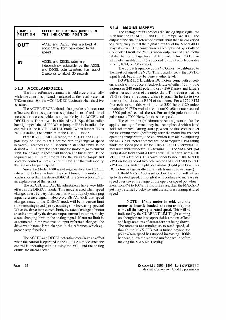
7/29/2019 bldc motor operation control.pdf
http://slidepdf.com/reader/full/bldc-motor-operation-controlpdf 30/46
Page 24 copyright 1993, 1994 by POWER TECIndustrial Corporation Used by permission
5.1.3 ACCEL AND DECELThe input reference command is held at zero internally
while the control is off, and is released at the level present atTB2 terminal 10 to the ACCEL/DECEL circuit when the driveis started.
The ACCEL/DECEL circuit changes the reference rate
of increase from a step, or near-step function to a fixed rate of increase or decrease which is adjustable by the ACCEL andDECEL pots. The rate will be affected by the Speed Controller
board jumper labeled JP2.When jumper JP2 is installed, thecontrol is in the RATE LIMITED mode. When jumper JP2 is
NOT installed, the control is in the DIRECT mode.In the RATE LIMITED mode, the ACCEL and DECEL
pots may be used to set a desired rate of change of speed between 2 seconds and 30 seconds in standard units. If thedesired ACCEL rate does not cause the motor to go to currentlimit, the change in speed will happen at a linear rate. If therequired ACCEL rate is too fast for the available torque andload, the control will reach current limit, and that will modifythe rate of change of speed
Since the Model 4000 is not regenerative, the DECELrate will only be effective if the coast time of the motor andload is shorter than the desired DECEL rate (see section 1.2 for an explanation of the terms).
The ACCEL and DECEL adjustments have very littleeffect in the DIRECT mode. This mode is used when speedchanges must be very fast, such as with a rapidly changinginput reference signal. However, BE AWARE that speedchanges made in the DIRECT mode will be in current limit(for increasing speeds) or by coasting (for decreasing speeds)!When the drive is in current limit, the rate of change of motor speed is limited by the drive's output current limitation, not bya rate changing limit in the analog signal. If current limit isencountered in the response to input reference changes, thedrive won’t track large changes in the reference which ap-
proach step functions.
The ACCEL and DECEL potentiometers have no effectwhen the control is operated in the DIGITAL mode since thecontrol is operating without using the VCO and the analogciruits are disconnected.
5.1.4 MAXIMUM SPEEDThe analog circuits process the analog input signal for
such functions as ACCEL and DECEL ramps, and JOG. Theoutput of the analog reference circuits must then be convertedto a frequency so that the digital circuitry of the Model 4000may take over. This conversion is accomplished by aVoltageControlled Oscillator (VCO), whose output in hertz is directly
related to the voltage level at its input. This VCO is aninfinitely variable circuit (as opposed to circuit which operatesin 512, 1024, or 2048 steps).
The output frequency of the VCO must be calibrated tothe input voltage of the VCO. This is usually set at the 10 VDCinput level, but it may be done at other levels.
POWER TEC Brushless DC motors come with encod-ers which will produce a feedback rate of either 120 (4 polemotors) or 240 (eight pole motors - 280 frames and larger)
pulses per revolution of the motor shaft. This requires that theVCO produce a frequency which is equal (in hertz) to twotimes or four times the RPM of the motor. For a 1750 RPMfour pole motor, this works out to 3500 hertz (120 pules/revolution X 1750 revolutions/ minute X 1/60 minutes/ second
= 3500 pulses/ second (hertz). For an eight pole motor, the pulse rate is 7000 Hertz for the same speed.
The calibration (maximum speed) adjustment for theapplied analog reference may be accomplished with a handheld tachometer. During start-up, when the time comes to setthe maximum speed (preferably after the motor has reachedoperating temperature), the calibration is made by adjustingthe MAX SPD potentiometer for the nameplate RPM ratingwhile the speed pot is set for +10VDC at TB2 terminal 10,measured with respect to TB2 terminal 12. The MAX SPD potis adjustable from about 2000 to about 10000 hertz (with a +10VDC input reference). This corresponds to about 1000 to 5000RPM on the standard two pole motor and about 500 to 2500RPM on the standard eight pole motor. (Eight pole brushless
DC motors are generally those with frames 280 or larger).If the MAX SPD pot is set too low, the motor will not run
up to its rated speed, although it will continue to increase itsspeed over the entire range of the operator speed pot adjust-ment from 0% to 100%. If this is the case, then the MAX SPD
pot may be turned clockwise until the motor is running at ratedspeed.
NOTE: If the motor is cold, and themotor is heavily loaded, the motor may notcome all the way up to rated speed. This will beindicated by the CURRENT LIMIT light comingon, though there is no appreciable amount of loadand large amounts of current are not being drawn.The motor is not running up to rated speed, al-though the MAX SPD pot is turned beyond the
point where speed has stopped increasing. If thishappens, allow the motor to run for a while beforemaking the MAX SPD setting.
JUMPERPOSITION
EFFECT OF PUTTING JUMPER INTHE INDICATED POSITION
OUT ACCEL and DECEL rates are fixed atabout 50mS from zero speed to fullspeed.
IN ACCEL and DECEL rates areindependently adjustable by the ACCELand DECEL potentiometers from about2 seconds to about 30 seconds.

7/29/2019 bldc motor operation control.pdf
http://slidepdf.com/reader/full/bldc-motor-operation-controlpdf 31/46
Model 4000 Instruction Manual Page 2
If the MAX SPD is set too high, the motor will stopincreasing in speed before the operator speed pot reaches itsfull range (100% clockwise). In this case the CURRENTLIMIT light will come on, though little current is being used,and the speed will be erratic. Turn the MAX SPD pot counter-clockwise until the CURRENT LIMIT light goes out (even if this is below base speed) to attain speed control, and then set
the MAX SPD pot (see the cold motor note above).Remember that this Model 4000 maximum speed ad-
justment is in reality just a calibration to the input reference of 10 VDC. It is not an absolute speed limit. If more than 10VDC is applied to the reference input, the motor will go faster (the input circuits clamp the input reference at +10.6 VDC andnegative voltages to -0.6VDC).
DO NOT ATTEMPT TO MAKE A MOTOR RUN ATANY SPEED GREATER THAN ITS BASE SPEED UN-LESS THE MOTOR WAS PURCHASED FOR HIGHSPEED OPERATION FROM THE FACTORY.
5.1.5 RAMP STOPThe RAMP STOP jumper, when installed, maintains the
control in the enable condition after a stop command is given(+24VDC is removed from TB2 terminal 5 by the ramp stop
button, or from TB2 terminal 4 when a switch or contact isused). The input speed reference is clamped to zero. This willdecelerate the motor to zero speed (the motor will coast to restif the coast time is greater than the DECEL time), and, whenthe motor gets below about 10 RPM, the control will shut off and after that it must be re-started with a RUN command toTB2 terminal 4.
If the RAMP stop jumper is not installed, a ramp stopshuts off the control and the motor will coast to a stop.
5.1.6 JOG FUNCTIONThe POWER TEC Model 4000 has a built-in JOG
function which may be used to turn the motor, usually for shor periods of time, without using the RUN function.
The JOG function does not seal in and hold itself on asdoes the RUN function. JOG will accelerate the motor veryrapidly when +24 VDC is applied to TB2 terminal 13 and then
decelerate the motor very rapidly to zero speed when thevoltage at terminal 13 is removed (the +24 VDC should comefrom a point after the Emergency Stop button). See section 4.4and Table 1 on page 17).
Speed is determined, in the analog mode, by the settingof the on-board JOG potentiometer, which is adjustable fromzero to about 15% of the MAX SPEED setting. (Speed in thedigital mode is determined by an external frequency which isapplied while the JOG function is active.)
There is no ACCEL or DECEL ramp in the analog JOGmode. The JOG reference will produce the JOG speed outputas a step function, where the acceleration or deceleration of themotor will be limited only by CURRENT LIMIT.
If a jog function with ACCEL and DECEL is desired, i
is better to use a non-latching RUN function for jog. This may be accomplished by opening up the connection to the RUNholding terminal TB2 terminal 5 and applying a RUN command to the RUN terminal at TB2 terminal 4. As long as TB2terminal 5 is open, the drive will RUN only as long as contactclosure on TB2 terminal 4 is maintained. When that contact isopened, the control will ramp stop the motor, if the ramp stop
jumper is installed. Speed in this mode will not come from theJOG pot, but from the reference input at TB2 terminal 10.
The JOG function is NOT locked out during the RUNfunction. If the JOG function is energized while the RUNfunction is active, the JOG function will override the RUN.
5.1.7 BI-DIRECTIONAL JOG
The capability for jogging in either direction in a systemmust be installed. It is not built into the system. This requiressimultaneous application of a directional signal (+24 VDC aTB2 terminal 14) and a speed signal (from the JOG pot inANALOG mode, or a frequency representing JOG speed inDIGITAL mode).
In ANALOG mode, the direction of the motor in JOG isdetermined by the presence or absence of +24 VDC at TB2terminal 14. With the FWD/REV terminal 14 at 0 VDC (or ifthe terminal is open), forward JOG will result if the JOG inpu(TB2 terminal 13) is activated. Activating the JOG with+24VDC applied at terminal 14 will result in a reverse JOGSpeed command in JOG comes from the JOG pot.
Bi-directional JOG may be accomplished in the sameway in the DIGITAL mode, but if the control remains in theDIGITAL mode during the JOG function, a frequency forthe JOG speed must be supplied at TB1 terminal 11, withrespect to TB1 terminal 9, which is NOT the drive commonTB1 terminal 10, which is the input for the DIGITAL modeis also referenced to terminal 9. Terminals 9, 10 and 11 onTB1 are an isolated circuit. See figure 16, section 4.5.2.
RAMP STOP JUMPER TABLE
ANALOG MODE
IN
Upon the RAMP STOP command, the motordecelerates to zero speed at the DECEL rate, orcoasts to stop if coast time is longer than DECELtime, then the control shuts off.
O U TControl shuts off immediately upon a RAMP STOPcommand. The motor will coast to a stop.
DIGITAL MODE
IN
The input frequency must be reduced to zero whenthe RAMP STOP command is given; the motorcoasts to a stop if the frequency is reduced fasterthan the coast time of the motor and load, then thecontrol shuts off.
O U TControl shuts off immediately upon a RAMP STOPcommand. The motor will coast to a stop.

7/29/2019 bldc motor operation control.pdf
http://slidepdf.com/reader/full/bldc-motor-operation-controlpdf 32/46
Page 26 copyright 1993, 1994 by POWER TECIndustrial Corporation Used by permission
5.2 DIGITAL MODE
When +24 VDC is applied to TB1 terminal 10 withrespect to TB1 terminal 9, the Model 4000 or is switched intothe DIGITAL MODE. This means that the speed of the drivewill no longer be dictated by the input reference at TB2terminal 10, nor will it respond to the ACCEL and DECEL
pots, or to the JOG function. MAX SPEED will have no effecton speed and the position of the JP2 jumper will have nomeaning in DIGITAL mode.
The control will now respond to a properly appliedsignal at TB1 terminal 11 with respect to TB1 terminal 9 (seesection 4.5). For four pole motors, this will be a square wavefrequency of 2 times the motor RPM desired in hertz (1750RPM = 3500 Hertz). Eight pole motors require a frequency of 4 times the motor RPM (1750 RPM = 7000 Hertz). Thereference to frequency is only for the sake of convenience indescribing the input waveform. The motor control will re-spond pulse for pulse to this input.
The standard eight pole motor, after processing by the pulse circuits, produces 240 feedback pulses for each revolu-
tion of the motor. Each reference pulse applied at TB1terminal 11 causes the motor to turn 1.5 degrees. This willapply whether the motor is at or near zero speed, or if it isturning at or near base speed. There isn’t any acceleration or deceleration rate associated with these pulses. They are ap-
plied and responded to immediately.Each pulse of reference increases the amount of torque
available to the motor (accelerates the motor) and each motor feedback pulse decreases the amount of torque available to themotor (decelerates the motor). For any given load and speed,the amount of torque required to run the load will cause anumber of pulses to be accumulated which is proportional tothe amount of torque required to run the load.
Once the amount of torque required to run the load is
developed, every pulse of reference must be answeredby a pulse of feedback from the motor or the control accumulatesenough pulses to go into current limit. The only times that
pulses will be lost is if the 4000 goes into current limit, or if a rapid decrease in the pules rate cannot be responded to
because of high inertia. The Model 4000 is not regenerativeand cannot brake the motor to match a rapidly decreasing pulsetrain. If the drive does not go into current limit and the load issuch that the motor can slow down as fast as the pulse rate, theneach pulse turns the motor 3 degrees. With eight pole motors,each pulse results in 1-1/2 degrees of rotation .
A GAIN potentiometer determines how many pulseswill be accumulated to reach current limit. At the minimumsetting of the GAIN pot (full counter-clockwise), about 90
pulses will be needed to reach current limit. At the maximumsetting (clockwise), only about 10 pulses will accumulate
before current limit is reached. Since each pulse represents 3degrees of a motor revolution, the motor cannot be off morethan 270 degrees from where it should be before current limitis reached. If 1750 RPM is being commanded, the motor must
run at exactly 1750 RPM, and can’t lose even a single revolu-tion, even over a period of time, regardless of load short of current limit. This means the speed regulation is zero percent(no loss of speed from no load to full load).
The frequency may be ramped from zero to the desiredspeed, or ramped from one speed to another, to avoid currentlimit. If losing pulses during acceleration or deceleration is not
a concern, the input frequency may be applied all at once, or even left running into the input while the control is off. Themotor must run at the commanded speed, or be in current limit.
In DIGITAL mode, a RAMP STOP command willdecelerate the motor to zero speed and shut off ONLY IF theRAMP STOP jumper JP1 is installed and the frequency at TB1terminals 11 and 9 (see section 4.5) is reduced to zero when theramp stop is initiated. If the frequency is not reduced to zero,the motor will continue to run at the speed dictated by thefrequency until some other action is taken (such as EMER-GENCY STOP). DO NOT USE RAMP STOP IN DIGITALMODE UNLESS EMERGENCY STOP IS CONNECTEDTO A PUSHBUTTON OR EMERGENCY STOP SYSTEM!
The JOG function may be simulated in DIGITAL mode
by applying a string of some number of pulses to the frequencyinput, then cutting off the string of pulses. It is also possibleto interrupt the TB1 terminal 10 connection during the JOGfunction to allow use of the analog JOG mode.
THERE IS NO MAXIMUM SPEED PROTECTIONWHILE OPERATING IN THE DIGITAL MODE.
IT IS THE RESPONSIBILITY OF THE USER TO MAKE SURE THAT THE SPEED COM-MANDED DOES NOT EXCEED THE MOTOR’SMAXIMUM SAFE SPEED WHILE OPERAT-ING IN THE DIGITAL MODE!!
5.3 CURRENT LIMIT
CURRENT LIMIT is the maximum amount of outputcurrent which the drive will be allowed to give when it is
powering the load, i.e., power is being drawn by the motor to perform work. The current limit is a peak-detecting circuitwhich will limit the current drawn on every PWM pulse. Theamount of current allowed is determined by the motor rating,allowing no more than 150% of nameplate current.
The current limit and the TRIP levels are calibrated for each individual control by a Horsepower calibration Resistor on Terminals 1 and 3 of TB3 on the Capacitor Board (part #141-106). Horsepower Calibration resistor values are listed insection 2.1 on page 9 of this manual. Those values are calcu-lated values which will be close to the best value for that sizeunit. The Trip and Horsepower calibration resistor values mayvary for the various sizes for the following reasons:
It is the nature of brushless DC motors that the amountof current drawn by any given Horsepower and Voltage rating

7/29/2019 bldc motor operation control.pdf
http://slidepdf.com/reader/full/bldc-motor-operation-controlpdf 33/46
Model 4000 Instruction Manual Page 2
will vary somewhat with the RPM’s of the motor. For thisreason, the Horsepower calibration resistors of units shippedfrom the factory may vary from unit to unit.
The hall effect sensors on the Capacitor Board may vary,not so much from unit to unit, as from batch to batch.
Each motor control is calibrated at the factory and itscalibration resistor is installed under actual load test.
Trip and current feedback calibration adjustments on theCapacitor Board are also set at the factory.
DO NOT CHANGE THE VALUE OF THE HORSE-POWER CALIBRATION RESISTOR WITHOUTCONSULTING THE FACTORY. THERE AREMANY FACTORS INVOLVED IN THE CHOICEOF THE CALIBRATION RESISTOR.
The current limit potentiometer may be adjusted any-where from 0% to 100% of its rotation. When the pot is at 0%(full CCW), the current limit is 0%. Full clockwise rotationgives 150% current. The pot may be set anywhere in itsrotation. The current setting is linear through the rotation (i.e.,
50% rotation is about 75% of full load current).Current limit in the motoring mode will result in the
motor finding a speed (which may be zero) at which it canmaintain the load at the current level allowed by the currentlimit. It will continue to find whatever speed it can maintainas long as it is in current limit, and that speed may vary.
When current limit is reached, it means that the controlis putting out all of the current allowed. If current limit isreached frequently, other than during periods of rapid accel-eration, the motor and/or the control size should be increased.
DO NOT ATTEMPT TO SOLVE THIS PROBLEMBY CHANGING THE CALIBRATION RESISTOR.THIS MAY CAUSE DAMAGE TO THE MOTOR
AND/OR THE CONTROL.
A condition which gives a “current limit” indication, butis not current limit, occurs when the motor is running as fast asits counter-EMF (CEMF is the voltage generated by the motor)will allow. This condition normally occurs with no load or alight load, and, most of the time,when the motor is cold. As thespeed command increases, the motor will not speed up anymore and the current limit light comes on, though little currentis being drawn.
This condition is referred to as “running against the buss” because the motor speed is being limited by the available buss voltage. A cold motor may do this below base speed, because a cold motor produces more CEMF (and more torque per amp also). After a cold motor warms up, its speed willincrease.
If a warmed up motor appears to be up against the buss,turn down the MAX SPEED until the current limit light goesout and recheck the speed.
5.4 GAIN AND STABILITY
A certain level of current must be drawn from thecontrol by the motor to develop the torque required to turn theload at any given speed. The POWER TEC Brushless DCmotor control works on the basis of balancing the number ofreference pulses against the number of feedback pulses from
the motor. The output current from the control is directly proportional to the number of pulses in an up/down counterwhich accumulates the difference between the number ofreference and feedback pulses. This difference is between the
NUMBER of pulses, NOT the frequency of the pulse train. Thecounter will accumulate pulses until it has developed thecurrent which the motor is demanding to satisfy the speedloop. The accumulated pulses will remain in the counter untithe load changes. Each feedback pulse from the motor represents 3 degrees of shaft rotation on a four pole motor.
Once the pulses necessary to develop the current areaccumulated, each one of the reference pulses must be an-swered by a feedback pulse from the motor. If the load isdecreased, the torque required is decreased, and the drive
responds by shedding some of the accumulated pulses.Increasing the GAIN pot reduces the number of pulses
needed to reach the required current level. This shows up as amore responsive control since the effect of each pulse is more
pronounced. When the GAIN pot is set fully CCW, the numberof pulses needed to reach current limit is about 90. Each pulseaccumulated will increase the current output of the control by1/60th of the full load current level. If the GAIN pot is turnedfully clockwise, only about 10 pulses will have to accumulate
before the control reaches current limit. Then each pulse wilincrease the current output of the drive by 1/10th of the currenlimit level. Only six or seven pulses will be required to reachfull load.
While this may seem desirable from the standpoint o
having a tight control, it produces a lot of “jitter” in the motorshaft at low speeds, particularly on unloaded or lightly loadedmotors. The large change in current level causes the motor to“overshoot” (it only has to go a few degrees to “overshoot”)This overshoot causes the counter to count down to zero. Thenit has to wait for more reference pulses before it can accumulate enough pulses to put out current again.
Experience has shown that in single motor applicationsa setting of about 50% on the GAIN pot gives good results inANALOG mode. In DIGITAL mode higher settings may beneeded so that the input pulses may be more closely tracked
The STABILITY adjustment is a dynamic adjustmentIn general, as the GAIN adjustment is turned higher, theSTABILITY adjustment must be increased. Lower settings othe STABILITY will produce a jittery operation while higher(CW) adjustments will produce sluggish operation.
The STABILITY adjustment has a 20:1 dynamic rangeSince different motor loads have different values of frictioninertia, and cyclic properties, there is no procedure to seSTABILITY. The best advice is to start at 50% of the porotation and adjust for best results.

7/29/2019 bldc motor operation control.pdf
http://slidepdf.com/reader/full/bldc-motor-operation-controlpdf 34/46
Page 28 copyright 1993, 1994 by POWER TECIndustrial Corporation Used by permission
Figure 28: Simplified schematic drawing of the Model 4000 power circuits.
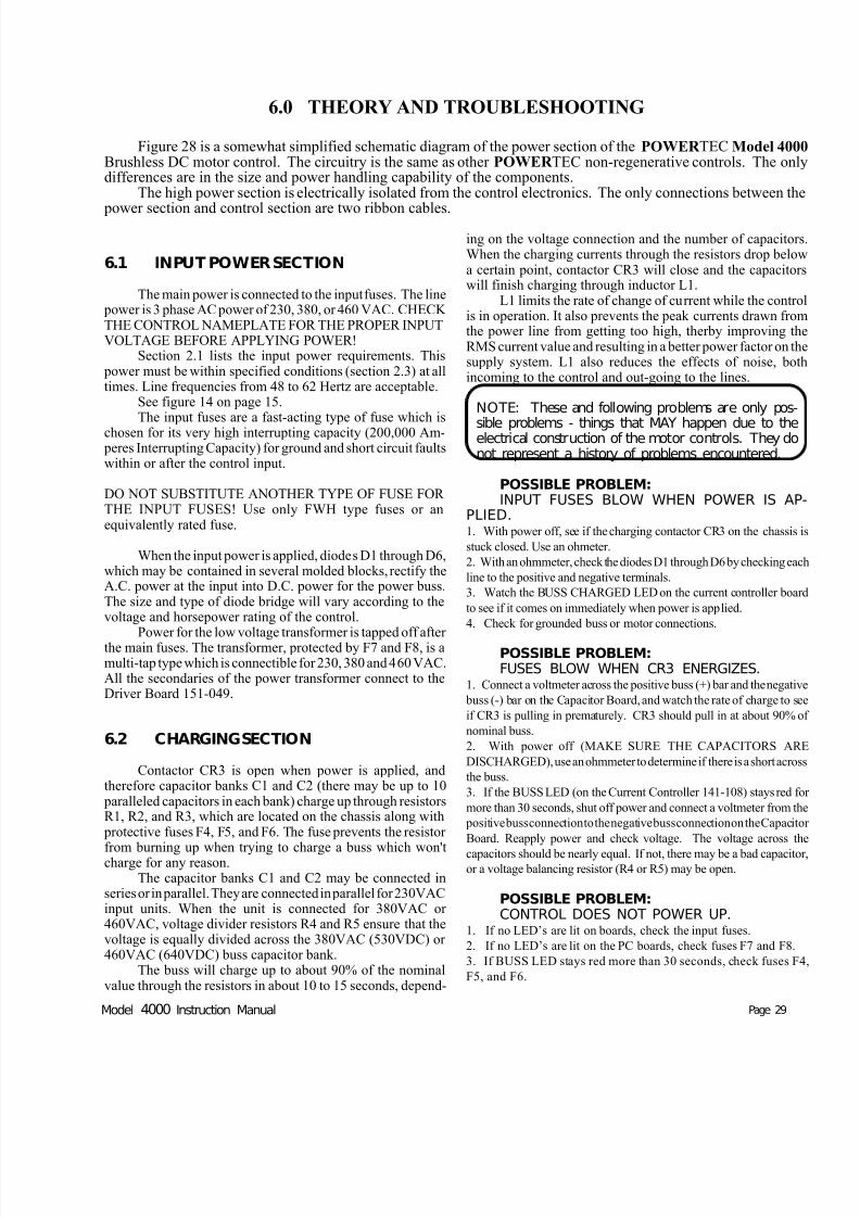
7/29/2019 bldc motor operation control.pdf
http://slidepdf.com/reader/full/bldc-motor-operation-controlpdf 35/46
Model 4000 Instruction Manual Page 29
6.1 INPUT POWER SECTION
The main power is connected to the input fuses. The line power is 3 phase AC power of 230, 380, or 460 VAC. CHECK THE CONTROL NAMEPLATE FOR THE PROPER INPUTVOLTAGE BEFORE APPLYING POWER!
Section 2.1 lists the input power requirements. This power must be within specified conditions (section 2.3) at alltimes. Line frequencies from 48 to 62 Hertz are acceptable.
See figure 14 on page 15.The input fuses are a fast-acting type of fuse which is
chosen for its very high interrupting capacity (200,000 Am- peres Interrupting Capacity) for ground and short circuit faultswithin or after the control input.
DO NOT SUBSTITUTE ANOTHER TYPE OF FUSE FOR THE INPUT FUSES! Use only FWH type fuses or anequivalently rated fuse.
When the input power is applied, diodes D1 through D6,which may be contained in several molded blocks, rectify theA.C. power at the input into D.C. power for the power buss.The size and type of diode bridge will vary according to thevoltage and horsepower rating of the control.
Power for the low voltage transformer is tapped off after the main fuses. The transformer, protected by F7 and F8, is amulti-tap type which is connectible for 230, 380 and 460 VAC.All the secondaries of the power transformer connect to theDriver Board 151-049.
6.2 CHARGING SECTION
Contactor CR3 is open when power is applied, andtherefore capacitor banks C1 and C2 (there may be up to 10
paralleled capacitors in each bank) charge up through resistorsR1, R2, and R3, which are located on the chassis along with
protective fuses F4, F5, and F6. The fuse prevents the resistor
from burning up when trying to charge a buss which won'tcharge for any reason.The capacitor banks C1 and C2 may be connected in
series or in parallel. They are connected in parallel for 230VACinput units. When the unit is connected for 380VAC or 460VAC, voltage divider resistors R4 and R5 ensure that thevoltage is equally divided across the 380VAC (530VDC) or 460VAC (640VDC) buss capacitor bank.
The buss will charge up to about 90% of the nominalvalue through the resistors in about 10 to 15 seconds, depend-
ing on the voltage connection and the number of capacitorsWhen the charging currents through the resistors drop belowa certain point, contactor CR3 will close and the capacitorswill finish charging through inductor L1.
L1 limits the rate of change of current while the controis in operation. It also prevents the peak currents drawn fromthe power line from getting too high, therby improving theRMS current value and resulting in a better power factor on thesupply system. L1 also reduces the effects of noise, bothincoming to the control and out-going to the lines.
NOTE: These and following problems are only pos-
sible problems - things that MAY happen due to theelectrical construction of the motor controls. They donot represent a history of problems encountered.
POSSIBLE PROBLEM:INPUT FUSES BLOW WHEN POWER IS AP-
PLIED.1. With power off, see if the charging contactor CR3 on the chassis i
stuck closed. Use an ohmeter.
2. With an ohmmeter, check the diodes D1 through D6 by checking each
line to the positive and negative terminals.
3. Watch the BUSS CHARGED LED on the current controller board
to see if it comes on immediately when power is applied.
4. Check for grounded buss or motor connections.
POSSIBLE PROBLEM:FUSES BLOW WHEN CR3 ENERGIZES.
1. Connect a voltmeter across the positive buss (+) bar and the negative
buss (-) bar on the Capacitor Board, and watch the rate of charge to see
if CR3 is pulling in prematurely. CR3 should pull in at about 90% o
nominal buss.
2. With power off (MAKE SURE THE CAPACITORS ARE
DISCHARGED), use an ohmmeter to determine if there is a short across
the buss.
3. If the BUSS LED (on the Current Controller 141-108) stays red fo
more than 30 seconds, shut off power and connect a voltmeter from the
positive buss connection to the negative buss connection on the Capacito
Board. Reapply power and check voltage. The voltage across the
capacitors should be nearly equal. If not, there may be a bad capacitoror a voltage balancing resistor (R4 or R5) may be open.
POSSIBLE PROBLEM:CONTROL DOES NOT POWER UP.
1. If no LED’s are lit on boards, check the input fuses.
2. If no LED’s are lit on the PC boards, check fuses F7 and F8.
3. If BUSS LED stays red more than 30 seconds, check fuses F4
F5, and F6.
Figure 28 is a somewhat simplified schematic diagram of the power section of the POWER TEC Model 4000Brushless DC motor control. The circuitry is the same as other POWER TEC non-regenerative controls. The onlydifferences are in the size and power handling capability of the components.
The high power section is electrically isolated from the control electronics. The only connections between the
power section and control section are two ribbon cables.
6.0 THEORY AND TROUBLESHOOTING
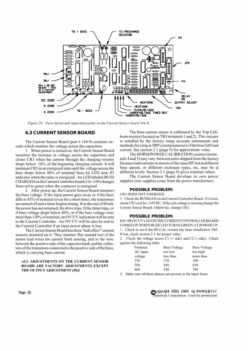
7/29/2019 bldc motor operation control.pdf
http://slidepdf.com/reader/full/bldc-motor-operation-controlpdf 36/46
Page 30 copyright 1993, 1994 by POWER TECIndustrial Corporation Used by permission
The buss current sensor is calibrated by the Trip Cali- brate resistor (located on TB3 terminals 1 and 2). This resistor is installed by the factory using accurate instruments andmethods for a trip at 300% (instantaneous) of the buss full loadcurrent. See section 2.1 (page 9) for approximate value.
The HORSEPOWER CALIBRATION resistor (termi-nals 4 and 5) may vary between units shipped from the factory
because load currents in motors of the same HP, but at different base speeds, or different enclosure types, etc, may be atdifferent levels. Section 2.1 (page 9) gives nominal values.
The Current Sensor Board develops its own power supplies (raw supplies come from the power transformer).
POSSIBLE PROBLEM:CR3 DOES NOT ENERGIZE.
1. Check the BUSS LED on the Current Controller Board. If it is on,
check CR3 coil for +24VDC. If the coil voltage is missing change the
Current Sensor Board. Otherwise, change CR3.
POSSIBLE PROBLEM:IOC OR OV/UV LED ON THE CURRENT CONTROLLER BOARD
COMES ON WHEN BUSS LED TURNS GREEN AT POWER UP.
1. Check to see if the HP CAL resistor has been installed on TB3.
If not, check section 2-1 for proper value.
2. Check the voltage across C1 (+ side) and C2 (- side). Check
against the following table:
Nominal Buss Voltage Buss Voltage
AC input too low too high
voltage less than more than
230 270 390
380 450 650
460 550 780
3. Make sure all three phases are present at the input fuses.
Figure 29: Parts layout and important points on the Current Sensor board 144-9.
6.3 CURRENT SENSOR BOARD
The Current Sensor Board (part # 144-9) contains cir-cuits which monitor the voltage across the capacitors:
1. When power is turned on, the Current Sensor Boardmonitors the increase in voltage across the capacitors andcloses CR3 when the current through the charging resistor drops below 10% of the beginning charging current. It willmaintain CR3 in an energized state until the voltage across the
buss drops below 80% of nominal buss.An LED near P3indicates when the relay is energized. An LED labeled BUSSCHARGED on the Current Controller board (141-108) changesfrom red to green when the contactor is energized.
2. After power up, the Current Sensor Board monitorsthe buss voltage. If the input power goes away or if the bussfalls to 85% of nominal (even for a short time), the transistorsare turned off and a timer begins timing. If at the end of 80mS,the power has not returned, the drive trips. If the timer trips, or if buss voltage drops below 80%, or if the buss voltage risesmore than 120% of nominal, an OV/UV indication will be sentto the Current Controller. An OV/UV will be also be sent tothe Current Controller if an input power phase is lost.
The Current Sensor Board has three “hall effect” currentsensors mounted on it. They monitor flux around two of themotor lead wires for current limit sensing, and in the wire
between the positive side of the capacitor bank and the collec-tors of the transistors connected to the positive side of the buss,which is carrying buss current.
ALL ADJUSTMENTS ON THE CURRENT SENSOR
BOARD ARE FACTORY ADJUSTMENTS EXCEPT
THE OUTPUT ADJUSTMENT (P6)!

7/29/2019 bldc motor operation control.pdf
http://slidepdf.com/reader/full/bldc-motor-operation-controlpdf 37/46
Model 4000 Instruction Manual Page 31
6.4 POWER OUTPUT SECTION
The output transistors are turned on and off (no morethan two on at the same time) to supply current to the brushlessmotor as determined by the speed and load regulation circuitryon the Speed and Current Controller boards.. Control power
for the output transistors come from the base driver boards (seefigure 28). The output transistors are protected by snubber elements to suppress high spikes and transients caused byswitching high voltages on an inductive load at high frequen-cies (up to 1.8 Kilohertz). “Free wheeling diodes” built intothe transistor packages carry circulating currents which occur when the transistors are off.
It is very important that the terminals T1, T2, and T3 beconnected to T1, T2, and T3 respectively on the motor. Theother connections at the motor end will vary with the speed,horsepower, and voltage of the motor.
The three base driver boards (part # 151-049) are switchedon and off by the Current Controller Board through the P2cable. The boards each serve two transistors. An LED
indicates that an output transistor is turned on. These lightsmay be difficult to see when the motor is lightly loaded due tothe Pulse Width Modulation. The length of time that thetransistors are on is proportional to load on the motor.
The base driver boards are each supplied by two wind-ings on the transformer, one winding for the A driver, and onewinding for the B driver. The base driver board supplies raw
power supplies (+24VDC and -24VDC to common) to theother PC boards, so one of the boards gets an extra windingconnection (the green-green/yellow-green winding) on its P1connector. It does not matter which on gets the connection.
The base and emitter wires going from the Base Driver boards are color coded to prevent mix-ups (figure 30). IT ISVITALLY IMPORTANT THAT THESE WIRES NOT GETMIXED UP. Connecting the wrong wires to the wrong transistors on the output WILL DAMAGE THE CONTROL!
POSSIBLE PROBLEM:
MOTOR DOES NOT TURN.1. Check to be sure T1, T2 and T3 are connected properly.
2. Make sure motor cable is properly connected.
3. Check for ENABLE light on Current Controller board.
4. Check to see if any Base Driver Board LED’s are lit.
5. Check for trip on Current Controller Board.
POSSIBLE PROBLEM:INPUT FUSES BLOW WHEN THE RUN OR JOG
CIRCUIT IS ACTIVATED.1. With power off (wait for the capacitors to discharge), disconnec
motor leads at T1, T2, and T3.
2. With an ohmmeter (preferably with a diode scale) check for
shorted transistor in the output bridge.
3. If no shorted transistor is found, power up with the motor leadT1, T2, and T3 disconnected. Turn speed pot to about 10%. If the
fuses do not blow when run is commanded, check the wiring to the
motor for grounds or shorts..
POSSIBLE PROBLEM:CURRENT LIMIT OR TRIP ON START OR JOG
1. Make sure the shaft of the motor is free to turn.
2. Uncouple the motor from the load, and try to operate the motor
3. Check motor connections, both power and cable.
4. Make sure that the HORSEPOWER CALIBRATION resistor i
installed on Capacitor Board.
Figure 30: Layout and connections of the Base Driver Board 151-049.

7/29/2019 bldc motor operation control.pdf
http://slidepdf.com/reader/full/bldc-motor-operation-controlpdf 38/46

7/29/2019 bldc motor operation control.pdf
http://slidepdf.com/reader/full/bldc-motor-operation-controlpdf 39/46
Model 4000 Instruction Manual Page 33
6.5 CURRENT CONTROLLER 141-108
Refer to the BLOCK DIAGRAM in figure 31.The Current Controller Board (part #141-108) contains
the main operational and protective logic of the POWER TEC
brushless DC motor control. It develops low level power supplies (+24VDC and -24VDC) from AC power suppliedthrough the cable connected to the base driver board anddevelops its own regulated supplies (+15VDC, -15VDC, and+5VDC). The Current Controller has the following functions:
1. It will lock out the drive on a fault if it recieves asignal from the capacitor board (Over or Under Voltage or OverCurrent), from the base driver board (Power Loss), or from its own fault monitor . When in the fault mode it turns off an optical coupler which communicates with the outside world(TB1 terminals 12 and 13). This coupler is normally turned on.STOP is NOT a fault mode.
A fault is reset when the run command at TB2 terminal4 is removed if the RESET SELECTOR (see figure 32 below)
is in the INT position (the left two pins of the jumper). If the jumper is on the right two pins (the MAN position), the controlwill not reset a fault unless the input power is turned off andthen on again, or the jumper is moved to the middle two pinsmomentarily (there should not be a RUN command presentwhen this is done!) and then placed on either the left two pins(internal reset) or the right two pins (manual reset). The controlwill not run with the jumper on the middle pins.
2. It determines if an outside frequency is called for (+24VDC between TB1 terminals 10 (+) and 9(-)), and substi-tutes the frequency at TB1 terminals 11(+) and 9(-) for theinternal VCO frequency.
3. It will accept a run enable request from the Speedcontroller board, and, if there is no fault, it will return an
ENABLE signal. The enable request is interlocked through aconnection on the Current Sensor board.
4. It compares a current reference command (velocityerror) from the Speed Controller board against the currentsignal recieved from the Current Sensor Board. If the actualcurrent is greater than the amount of current allowed, thecurrent output is limited the by adjusting the pulse-widthmodulation. Current limit is checked every PWM pulse.
5. It takes a sample of the current in a sample and holdcircuit, where it may be monitored by external means betweenTB1 terminals 14(-) and 16(common). The current level iscalibrated by the Horsepower Calibration resistor on theCurrent Sensor board (-2VDC = 150% of full load current).
6. It receives the encoder signals from the encoder onthe motor. There are five channels. Three of the channels areused to determine shaft position (HS1, HS2, and HS3). TheCurrent Controller board generates the complementary sig-nals and feeds all six signals to the EPROM in the L3 socket(a 141-300 is standard). The position channels of the encoder are used by the Current Controller to determine the outputtransistor firing sequence. There are three lights on the Current
Controller board which monitor the position encoder channels(labelled HS1, HS2, and HS3).
The other two channels (HS4 and HS5) are used toregulate speed and to determine direction of rotation of themotor. The signals from HS4 and HS5 have the same pulserate, but they are in "quadrature" (90° out of phase ). TheCurrent Controller board detects the leading and trailing edges
of each of the speed signals and combines them to allow theEPROM to select a X4, X2, or X1 feedback rate. The standardEPROM (141-300) multiplies the single channel pulse rate byfour (X4). For a four-pole motor (140, 180, 210, and 250frames), the sixty pole encoder wheel supplies a 30 PPRfeedback rate in each of the HS4 and HS5 channels. Thestandard EPROM multiplies this by four to supply a 120PPRfeedback rate to the Speed Controller board. Other EPROMmay supply other feedback rates.
7. The Current Controller board gives the signals to the base driver boards to turn the output transistors on and off, asdetermined by the position encoder signals, by the direction ofrotation commanded, and controls the PWM frequency ac-cording to the motor conditions.
POSSIBLE PROBLEM:ENCODER LIGHT OR LIGHTS NOT CHANGING
1. Check the power supply at TB1 terminals 8(+) and 7(-). It should
be 5.0VDC +/- 0.1VDC.
Figure 32: Major parts of the 141-108 Current Controller board.

7/29/2019 bldc motor operation control.pdf
http://slidepdf.com/reader/full/bldc-motor-operation-controlpdf 40/46
Page 34 copyright 1993, 1994 by POWER TECIndustrial Corporation Used by permission
2. Check the signals at TB1 terminals 2, 3, and 4. The proper signals
are illustrated on page 8 of the Motor manual.
3. Change the Current Controller Board.
6.6 SPEED CONTROLLER 141-107
The Speed Controller Board (part #141-107) handles thespeed control of the control. It also takes care of the start, stop,
jog, emergency stop, and reverse control logic functions of theBrushless DC motor control.
CONTROL LOGIC FUNCTIONS -- The SpeedController supplies +24VDC (terminal 8 on TB2) to theoperator devices and accepts signals for Emergency Stop(immediate coast stop) on terminal 7 on TB2, ramp stop(decelerate to zero speed before shutting off - E.Stop mustremain energized during the ramp stop period) on TB2 termi-nal 5, and RUN (momentary with holding contact, or two-wire) on TB2 terminal 4. A jog function is entered on TB2terminal 13, but be aware that the Jog function will override theRUN function if it is activated while the RUN is active.
The direction of rotation of the motor when operating in
either digital or analog input mode is determined by the presence of +24VDC at the reversing terminal. If +24VDC isnot applied to TB2 terminal 14, the motor will operate in the"forward" direction. Applying +24VDC at TB2 terminal 14will cause the motor to decelerate to zero speed (if it is notalready there), electronically reverse the motor at zero speed,and then accelerate the motor at the ACCEL rate to the speedset at the speed pot.
If the control is operating in the digital mode, thefrequency input must be reduced to zero when the reversecommand is applied, then the frequency can be reapplied oncethe motor comes to a stop.
SPEED REGULATOR FUNCTION -- All customer
adjusments are located on the Speed Controller board. Thereare also jumpers to range the ACCEL and DECEL times andto set up the RAMP STOP function.
The speed command is ramped to and from changingsetpoints by the ACC/DEC circuit (removing the JP2 jumper shortens the time to about 50 milliseconds full scale). Theoutput of the ACC/DEC circuit is fed to a voltage-controlledoscillator (VCO) which is linear within 0.5% over the speedrange. The VCO frequency is routed through the CurrentController in case an external frequency is desired.
The reference frequency is routed to the up/down counter as “count up” pulses. The pulses from the speed encoder (Current Controller Board) is routed to the up/down counter as“count down” pulses. A register holds the accumulatednumber of error pulses, which is converted into an error voltage to be used as a current reference by the CurrentController. The number of pulses accumulated is directly
proportional to the output current of the control.
Under all normal operating conditions (whichexcludescurrent limit), the number of pulses received from the speedreference must be balanced by the feedback pulses from themotor. In the standard control, the pulse rate from the motor will be 120 pulses per revolution (PPR). If the motor is notstarted, or at zero speed, those numbers are zero and zero. If themotor is running with a steady speed reference, the reference
and feedback pulse rates must be the same or the counter wouldsaturate and the drive would be in current limit.
When a change is made from a steady state condition,such as an increase in speed command (starting from zero is anexample), pulses are accumulated in the counter until themotor is drawing enough current to accelerate the shaft andreturn more pulses from the encoder than are coming from thereference. Each extra reference pulse increases the outputcurrent from the control. When the current is sufficient toaccellerate the motor to a speed higher than that required by thereference pulses, the extra feedback pulses caused by thehigher speed will reduce the current level until the reference
pulses and the feedback pulses are again in balance. Notice that this has nothing to do with the frequency of
the pulse trains. The important thing is the number of pulses inthe reference versus the number of pulses in the feedback pulsetrain. The counter stores the difference in the number of total
pulses. As long as the counter does not saturate (an adjustable
Figure 33: Major parts of the 141-107 Speed Controller board.

7/29/2019 bldc motor operation control.pdf
http://slidepdf.com/reader/full/bldc-motor-operation-controlpdf 41/46
Model 4000 Instruction Manual Page 35
GAIN function), the motor will turn according to the number of pulses received.
LED indicators are provided for RUN, CURRENTLIMIT, and ZERO SPEED.6.7 TROUBLESHOOTING
When troubleshooting the Model 4000, it is just as
important to know WHEN something happens as it is to knowWHAT happens. In other words, the SEQUENCE OF EVENTSis important in trying to resolve what, if any, problems theremay be. There may be times when it seems that something iswrong, but the problem may actually be in the sequence of events.
A Start Up Procedure is shipped with each control. Itshould be used to put the unit into operation and may also beused to find problems. If problems are experienced in theoperation of the control, go back and follow the start up
procedure from the beginning, and make note of when and howthings go wrong. This way, POWER TEC's service personnelwill be able to pinpoint the problem more easily.
EFFECTIVE AND EFFICIENT TROUBLE-SHOOTING ALSO REQUIRES A SUPPLY OF SPAREPARTS FOR THE EQUIPMENT BEING WORKED ON.
Before attempting to do any troubleshooting, studyfigure 13 on page 14 (standard connection diagram), readsections 4 and 5 of this manual, and look at the power diagram(figure 28 on page 28) and the block diagram on page 32(figure 31). This will familiarize you with the circuitry in-volved.
The LED indicators are designed to give a ready indica-tion of the status of the control. They are an immediate visualreference of the present conditions in the drive, and may beused as a troubleshooting aid. It is recommended that the status
of these LED's be checked frequently while starting up and/or troubleshooting the control.
Using the LED indicators, here are some suggestions asto possible problems and solutions, based upon the electricalwiring of the Model 4000 motor control (follow the sugges-tions in the order given):
PWR LED (green) This LED should be ON whenever thereis power applied to the control. If the LED is not ON:1. Check incoming power.2. Turn off power, wait 3 minutes, and check fuses FU1, FU2,FU3, and FU4.3. Re-apply power, and check the following power supplies:
TB2 terminal 12 is common+24 VDC at TB2 terminal 8+24 VDC at TB2 terminal 17-24 VDC at TB2 terminal 3+10 VDC at TB2 terminal 10+5 VDC at TB1 terminal 8If supplies are O.K., the PWR LED may be bad.
4. Change Current Controller Board.
5. Change Driver Board.6. Change power transformer T1.7. Change entire controller.
BUSS LED (red on power-up, then green) This LED should be RED when power is first applied, then change to greenwithin 30 seconds.
If it stays RED for more than 30 seconds:1. Check incoming power.2. Turn off power, wait 3 minutes, and check all fuses(including the one on the capacitor board).3. Re-apply power and listen for the contactor CR3 on thechassis pulling in.4. Replace Current Sensor Board.5. Replace Current Controller Board.6. Change entire control.
OV / UV (red) This LED will come on to indicate severaadverse conditions which cause an electronic trip. If this LEDcomes on:1. Check the incoming power.
2. Turn off power, wait 3 minutes, and check the fuses.3. Reapply power and listen for the CR3 contactor pulling in4. Ckeck the buss voltage (see capacitor board layout in figure29 on page 30).
If buss voltage is greater than 1.6 times nominal line voltage for that unit
the trip is overvoltage (OV).
If buss voltage is less than 1.2 times nominal line voltage for the unit, i
is under-voltage (UV).
It may be necessary to check the buss voltage while running under load
5. Replace Current Sensor Board.6. Replace Current Controller Board.
PL (red) This LED indicates one of several power problemon the incoming lines. If this LED is on:
1. Check the incoming power.2. Turn off power, wait 3 minutes, and check the fuses.3. Check incoming power while the control is running underload (it may be necessary to use an oscilloscope.4. Change the Current Controller board.
IOC (red) This LED indicates dangerous current levels haveoccured in the output transistors. If this LED is on:1. If control will run, check motor current with AC clamp onammeter while the motor is under load.2. Disconnect motor and try to run.3. Call POWER TEC service.
ENABLE (yellow) This LED indicates that the control is inthe RUN mode (the RUN LED on the Speed Controller boardshould also be on) and there are no faults. If the motor is norunning, a speed reference signal may be needed.
If this LED stays off, or goes off when a RUNcommand is given to the control:1. Check to see if a trip indicator is on.

7/29/2019 bldc motor operation control.pdf
http://slidepdf.com/reader/full/bldc-motor-operation-controlpdf 42/46
Page 36 copyright 1993, 1994 by POWER TECIndustrial Corporation Used by permission
2. Check for +24 VDC at TB2 terminals 7, 5 and 4 (TB2terminal 12 is common).3. Make sure the ribbon cables are firmly seated.4. Change the Current Controller board.5. Change the Speed Controller board.
HS1, HS2, HS3 (red) Thess LED's indicate the operation of
the LED switches as the motor turns.If one or more of these LED's is not working:
1. See section 6.4 on page 33.2. Check the hall sensors as in CURRENT LIMIT sectionunder Speed Controller board below.
SPEED CONTROLLER 147-101
RUN (green) This LED indicates that the control is beinggiven a RUN command.
If this LED is not on:1. Check for +24 VDC at TB2 terminal 8, 7, and 4 (TB2terminal 12 is common).2. Change the Speed Controller board.
3. Change the Current Controller board.
CURRENT LIMIT (red) This LED indicates the UP/DOWN counter is saturated.
If this LED is on:1. Make sure that the motor is physically capable of turning.2. Check the current going to the motor (when the motor isstalled, this will require a DC amp probe).3. Check the hall effect feedback terminals on TB1 whileturning the motor by hand (the control power must be on, butthe ESTOP circuit should be open).
TB1 terminal 1 is common
TB1 terminals 2, 3, and 4 will switch between 0 VDC and 8.8 VDC
TB1 terminals 5 and 6 will switch between 0 and 8.8 VDC, but at a
much faster rate
TB1 terminal 7 is also common
TB1 terminal 8 is +5 VDC
ZERO SPEED (yellow) This LED indicates that the motor is turning faster than 10 RPM.
If this LED is not on:1. Check to make sure the motor is turning.2. Check the hall sensor input lights HS1, HS2, and HS3 onthe Current Controller board.3. Change the Speed Controller board.4. Change the Current Controller board.
CURRENT SENSOR 144-9
THERMAL (yellow) This LED indicates that the heatsink thermal is closed (not overheated).
If this LED is not on:1. Check for -24 VDC at TB3 terminal 9 (TB3 terminal 10 iscommon). CR3 should be energized.
2. Check for -24 VDC at TB3 terminal 6. If missing, and step1 is correct, thermal is open or wire is broken.3. Check the wires for loose or broken connections.4. Change the Current Sensor board.5. Change the heatsink thermal switch.
UNDERVOLTAGE (red) This LED indicates that an
undervoltage condition of less than 80% buss level hasoccurred (this is a latching indication which is reset by thestart/stop circuits).
If this LED is on:1. Check the buss voltage across the entire buss and acrosseach half of the buss (on 380VDC and 460VAC controls). CR3should be energized. If the voltage is correct, press the stop
button and restart the control. If the comes on again, or if itremains on, proceed to next step.2. Check the voltage at the Current Sensor board from A to B(should be 0 VDC if CR3 is in). [See figure 29 on page 30 for locations of points A, B, and C]3. Check the voltage from A to C on the Current Sensor board(it should be the buss level).
4. Change the Current Sensor board.
UNDERVOLTAGE TIME OUT (red) This LED indicatesthat power was lost at the input for at least 80 milliseconds,and/or an undervoltage condition of less than 80% buss levelhas occurred (this is a latching indication which is reset by thestart/stop circuits).
If this LED is on:1. Check the buss voltage across the entire buss and acrosseach half of the buss (on 380VDC and 460VAC controls). CR3should be energized. If the voltage is correct, press the stop
button and restart the control. If the comes on again, or if itremains on, proceed to next step.2. Check the voltage at the Current Sensor board from A to B
(should be 0 VDC if CR3 is in). [See figure 29 on page 30 for locations of points A, B, and C]3. Check the voltage from A to C on the Current Sensor board(it should be the buss level).4. Change the Current Sensor board.5. Change the Current Controller board.
OVERVOLTAGE (red) This LED indicates that an over-voltage condition of more than 115% buss level has occurred(this is a latching indication which is reset by the start/stopcircuits).
If this LED is on:1. Check the buss voltage across the entire buss and acrosseach half of the buss (on 380VDC and 460VAC controls). CR3should be energized. If the voltage is correct, press the stop
button and restart the control. If the comes on again, or if itremains on, proceed to next step.2. Check the voltage at the Current Sensor board from A to B(should be 0 VDC if CR3 is in). [See figure 29 on page 30 for locations of points A, B, and C]3. Check the voltage from A to C on the Current Sensor board(it should be the buss level).4. Change the Current Sensor board.
HOT (red) This LED is the latched version of THERMAL.

7/29/2019 bldc motor operation control.pdf
http://slidepdf.com/reader/full/bldc-motor-operation-controlpdf 43/46
Model 4000 Instruction Manual Page 37
Figure 34: Some typical physical configurations of power semiconductors.

7/29/2019 bldc motor operation control.pdf
http://slidepdf.com/reader/full/bldc-motor-operation-controlpdf 44/46
Page 38 copyright 1993, 1994 by POWER TECIndustrial Corporation Used by permission
Figure 35: Connections of the Model 4000 to the optional POWER TEC DIGIMAX IV.

7/29/2019 bldc motor operation control.pdf
http://slidepdf.com/reader/full/bldc-motor-operation-controlpdf 45/46
Model 4000 Instruction Manual Page 39
7.0 SPARE PARTS
Spare parts are necessary to assure continuation of service in the event that something goes wrong. Theability to effectively troubleshoot and repair motor controls requires that spare parts be available. It is stronglyrecommended that some or all of the following parts be carried in stock, and that at least one person becomefamiliar with them and their usage in the repair of POWER TEC controls.
QUANTITY DESCRIPTION PART NO.
1 Current Controller PCB 141-108
1 Speed Controller PCB 141-107
1 Base Driver PCB 151-049
1 Current Sensor Board 144-9.3
3 Fuses F4, F5, F6 FNQ1/2
1 Fuse F7, F8 FNQ 2
1 Diode Bridge See Below
1 Transistor Bridge See Below
1 Transformer T1 151-49
1 Charge Resistor P/FS02-65-500
H.P. VOLTAGE MODEL DIODE TRANSISTOR MAIN FUSES
60 230 4000 IRKE91-12 KS621K60 FWH-25075 230 4000 IRKE91-12 KS621K60 FWH-250
100 380 4000 IRKE91-12 KS621K60 FWH-250125 380 4000 IRKE91-12 KS621K60 FWH-250
100 460 4000 IRKE91-12 KS621K40 FWH-250125 460 4000 IRKE91-12 KS621K60 FWH-250150 460 4000 IRKE91-12 KS621K60 FWH-250
When ordering spare parts, have the serial number of your control(s) handy.Parts may be substituted by POWER TEC due to availability.Older drives may have to use cross-referenced parts.

7/29/2019 bldc motor operation control.pdf
http://slidepdf.com/reader/full/bldc-motor-operation-controlpdf 46/46