bldc motors and vector control pmsm drives, 1 pmsm … control using a three-phase, six-step 120°...
TRANSCRIPT

© Festo Didactic 86373-00 11
When you have completed this exercise, you will be familiar with six-step 120° modulation. You will know how to control a PMSM (i.e., adjust the rotation speed of a PMSM) using a three-phase, six-step 120° modulation inverter, as well as the main drawbacks related to this control method.
The Discussion of this exercise covers the following points:
Operation of a three-phase, six-step 120° modulation inverter
PMSM control using a three-phase, six-step 120° modulation inverter
Operation of a three-phase, six-step 120° modulation inverter
Six-step 120° modulation is a type of modulation that can be implemented in a three-phase inverter. Figure 8 shows the typical configuration of a three-phase, six-step 120° modulation inverter connected to a three-phase load.
PMSM Control Using a Three-Phase, Six-Step 120 Modulation Inverter
Exercise 1
EXERCISE OBJECTIVE
DISCUSSION OUTLINE
DISCUSSION
For brevity purposes, a
three-phase inverter in
which six-step 120° modula-
tion is implemented is re-
ferred to as a three-phase,
six-step 120° modulation
inverter.

Exercise 1 – PMSM Control Using a Three-Phase, Six-Step 120û Modulation Inverter Discussion
12 © Festo Didactic 86373-00
Figure 8. Typical configuration of a three-phase, six-step 120° modulation inverter connected to a three-phase load.
When implementing six-step 120° modulation in a three-phase inverter, rectangular switching control signals are sent to the electronic switches of the three-phase inverter. These switching control signals cause the three-phase inverter to convert the dc power supplied by the dc power source into ac power. Six-step 120° modulation does not use PWM and therefore results in fixed voltage at the ac side of the three-phase inverter. In order to vary the voltage at the ac side of the three-phase inverter, it is necessary to adjust the voltage at the dc side of the inverter (i.e., the dc power source voltage). Because of this, three-phase, six-step 120° modulation inverters are typically powered by a variable-voltage dc power source (see Figure 8).
Figure 9 shows the switching control signals for each electronic switch of the three-phase, six-step 120° modulation inverter in Figure 8. Figure 9 also shows the resulting voltage across each phase of the three-phase, six-step 120° modulation inverter. Note that the amplitude of the voltage across each phase of the inverter is equal to half the voltage of the dc power source. Also note that the phase voltage waveforms in Figure 9 are obtained when the three-phase, six-step 120° modulation inverter is connected to a load that is purely resistive (in this case, the waveforms of the line currents are identical to the phase voltage waveforms).
Variable-voltagedc power source
A
B
C
B
A
C
N
Three-phase inverter
Switching control signals
Negative
Positive
6
Six-step 120° modulation controller
Inverter
frequency

Exercise 1 – PMSM Control Using a Three-Phase, Six-Step 120û Modulation Inverter Discussion
© Festo Didactic 86373-00 13
Figure 9. Switching control signals sent to each electronic switch of a three-phase, six-step 120° modulation inverter and resulting voltage across each phase.
switchingcontrol signal
switchingcontrol signal
switchingcontrol signal
switchingcontrol signal
switchingcontrol signal
switchingcontrol signal
Vo
lta
ge
(V
) V
olta
ge
(V
) V
olta
ge
(V
) V
olta
ge
(V
) V
olta
ge
(V
) V
olta
ge
(V
)
Phase A voltage
( )
Phase B voltage
( )
Phase C voltage
( )
Vo
lta
ge
(V
) V
olta
ge
(V
) V
olta
ge
(V
)
0° 60° 120° 180° 240° 300° 0°
Step 1 Step 2 Step 3 Step 4 Step 5 Step 6
0
0
0
0
0
0
0
0
0
Exercise 1 – PMSM Control Using a Three-Phase, Six-Step 120û Modulation Inverter Discussion
14 © Festo Didactic 86373-00
As Figure 9 shows, in a three-phase, six-step 120° modulation inverter, a complete commutation cycle is divided into six steps of 60°. Also, each switching control signal is high for an angular interval of 120° (hence the name 120° modulation), then low for an angular interval of 240°. During any given step, only
two of the three pairs of electronic switches (i.e., - , - , and - ) contain a switch that is on, which means that in the other pair of electronic switches, both switches are off. Therefore, at any moment, current only flows in two of the three phases of the inverter, while no current flows in the third phase.
The frequency of the voltages at the ac side of the three-phase, six-step 120° modulation inverter is the same as the frequency of the switching control signals. For example, when one cycle of the switching control signals shown in Figure 9 repeats 50 times per second, the frequency of the voltages at the ac side of the three-phase, six-step 120° modulation inverter is equal to 50 Hz. Note that the frequency of the voltages produced by the three-phase, 120° modulation inverter
depends on the value of the inverter frequency ( ) parameter input to the six-step 120° modulation controller shown in Figure 8.
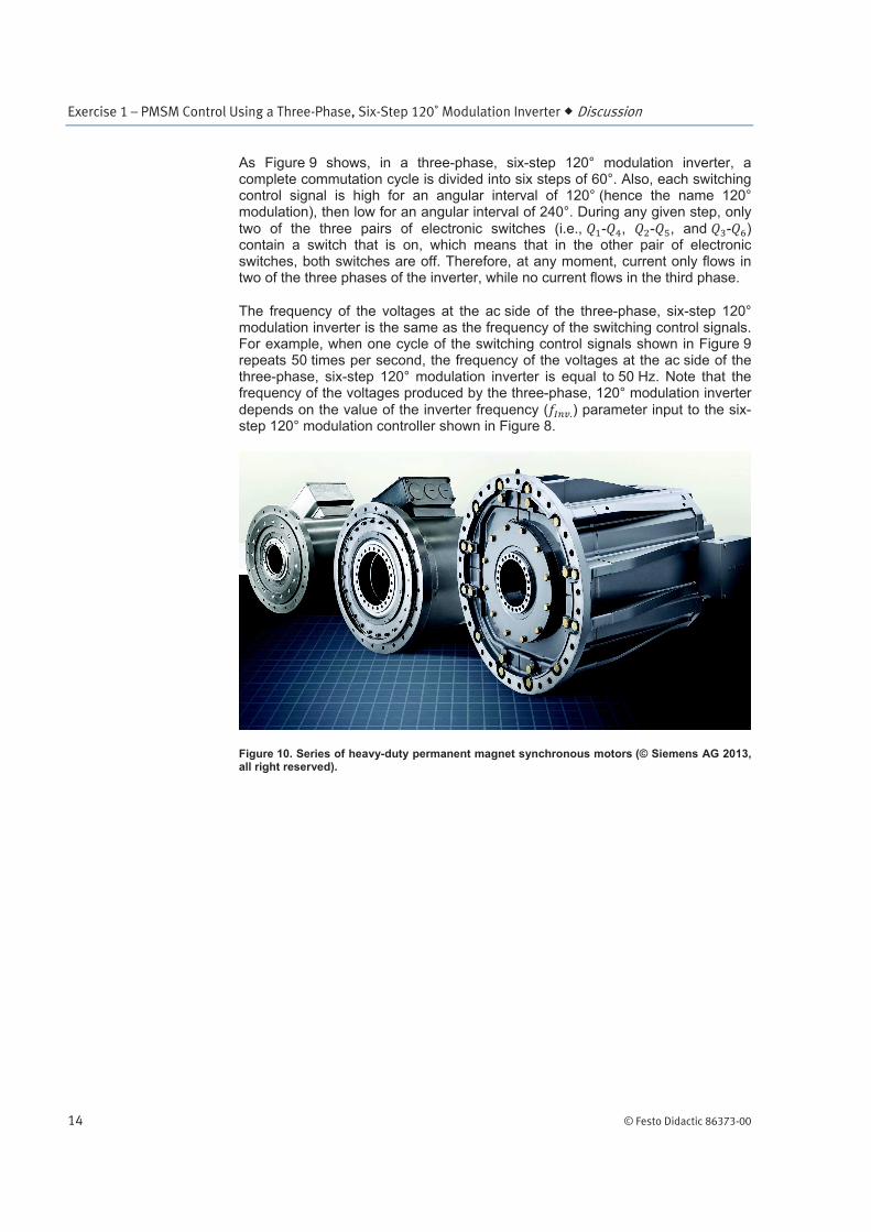
Figure 10. Series of heavy-duty permanent magnet synchronous motors (© Siemens AG 2013, all right reserved).
Exercise 1 – PMSM Control Using a Three-Phase, Six-Step 120û Modulation Inverter Discussion
© Festo Didactic 86373-00 15
PMSM control using a three-phase, six-step 120° modulation inverter
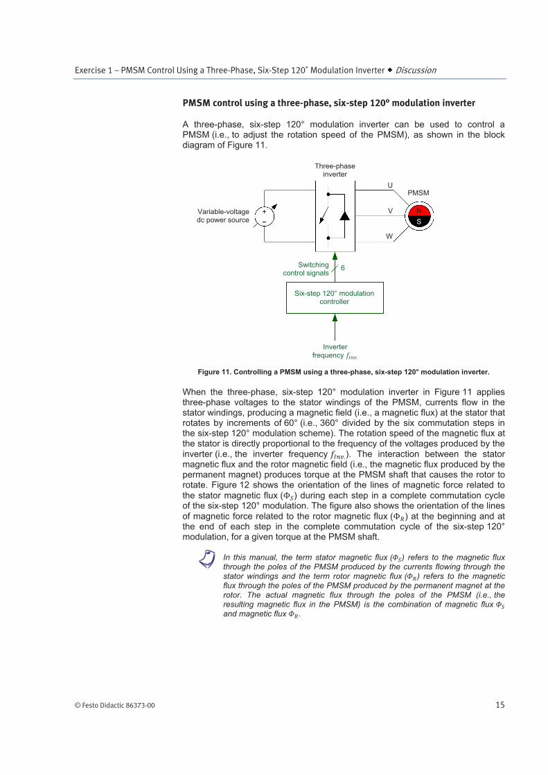
A three-phase, six-step 120° modulation inverter can be used to control a PMSM (i.e., to adjust the rotation speed of the PMSM), as shown in the block diagram of Figure 11.
Figure 11. Controlling a PMSM using a three-phase, six-step 120° modulation inverter.
When the three-phase, six-step 120° modulation inverter in Figure 11 applies three-phase voltages to the stator windings of the PMSM, currents flow in the stator windings, producing a magnetic field (i.e., a magnetic flux) at the stator that rotates by increments of 60° (i.e., 360° divided by the six commutation steps in the six-step 120° modulation scheme). The rotation speed of the magnetic flux at the stator is directly proportional to the frequency of the voltages produced by the inverter (i.e., the inverter frequency ). The interaction between the stator magnetic flux and the rotor magnetic field (i.e., the magnetic flux produced by the permanent magnet) produces torque at the PMSM shaft that causes the rotor to rotate. Figure 12 shows the orientation of the lines of magnetic force related to
the stator magnetic flux ( ) during each step in a complete commutation cycle of the six-step 120° modulation. The figure also shows the orientation of the lines
of magnetic force related to the rotor magnetic flux ( ) at the beginning and at the end of each step in the complete commutation cycle of the six-step 120° modulation, for a given torque at the PMSM shaft.
a In this manual, the term stator magnetic flux ( ) refers to the magnetic flux through the poles of the PMSM produced by the currents flowing through the stator windings and the term rotor magnetic flux ( ) refers to the magnetic flux through the poles of the PMSM produced by the permanent magnet at the rotor. The actual magnetic flux through the poles of the PMSM (i.e., the resulting magnetic flux in the PMSM) is the combination of magnetic flux and magnetic flux .
Variable-voltagedc power source
Three-phase inverter
N
S
PMSM
Switchingcontrol signals
6
Six-step 120° modulation controller
Inverter
frequency
U
V
W

Exercise 1 – PMSM Control Using a Three-Phase, Six-Step 120û Modulation Inverter Discussion
16 © Festo Didactic 86373-00
Figure 12. Direction of the lines of magnetic force related to the stator magnetic flux and rotor magnetic flux in the PMSM for each of the six steps in a complete cycle of the six-step 120° modulation scheme.
N
N’
S
S’
60°
0°
60°
120°
180°
240°
300°
U
U’
V’
V
W’
W
N
U
U’
V’
V
W’
W
N
U
U’
V’
V
W’
W
N
U
U’
V’
V
W’
W
N
U
U’
V’
V
W’
W
N
U
U’
V’
V
W’
W
N
NN’
S
S’
60°
N
N’
S
S’
60°
N N’
SS’
60°
N
N’ S
S’60°
N
N’S
S’ 60°
’
’
’
’
’
’

Exercise 1 – PMSM Control Using a Three-Phase, Six-Step 120û Modulation Inverter Discussion
© Festo Didactic 86373-00 17
Figure 12 shows that the rotor of the PMSM rotates in the clockwise direction (illustrated by the orientation of the rotor magnetic flux) as the orientation of the stator magnetic flux rotates step by step from step 1 to step 6 of the commutation sequence. At the beginning of each step, the stator magnetic
flux momentarily leads the rotor magnetic flux . However, during the time interval leading to the next step of the commutation sequence, the rotor magnetic
flux progressively catches up with the stator magnetic flux , then begins to lead the stator magnetic flux . The initial lag of the rotor magnetic flux in relation to the stator magnetic flux (i.e., the rotor magnetic flux lag at the beginning of each step) is proportional to the torque produced by the PMSM, which itself depends on the mechanical load applied to the PMSM (i.e., the load torque). The higher the mechanical load applied to the PMSM, the higher the
PMSM torque, and thus the greater the initial lag of the rotor magnetic flux in relation to the stator magnetic flux . Consequently, powering a PMSM using a three-phase, six-step 120° modulation inverter allows the PMSM rotation speed to be controlled, but does not provide any control over the torque produced by the PMSM.
PMSM control using a three-phase, six-step 120° modulation inverter has major drawbacks and is not used in actual applications. The three main drawbacks are listed below:
1. The PMSM rotation speed can only be varied by gradually adjusting the frequency of the voltages applied to the PMSM stator windings (i.e., the inverter frequency) to avoid the PMSM rotor from pulling out of synchronization. Any significant and sudden variation in the frequency of the voltages applied to the stator windings of the PMSM causes the magnetic flux at the stator to suddenly rotate at a faster speed and the rotor to pull out of synchronization because of its inertia and that of the load (if any). In other words, the torque required to accelerate the rotor in this situation exceeds the PMSM pull-out torque. Because of this, bringing the PMSM rotation speed to the desired value is a rather slow process.
2. Any significant and sudden increase in the mechanical load applied to the PMSM causes the rotor to pull out of synchronization. This is due to the lack of control over the torque produced by the PMSM. Consequently, it cannot be adjusted as required when the mechanical load applied to the PMSM varies suddenly, thereby causing the rotor to pull out of synchronization.
3. The magnitude of the voltages produced by the three-phase inverter must be continually adjusted at the same time as their frequency in order to maintain the V/f ratio at the PMSM constant. This is necessary to prevent either saturation of the PMSM stator or the stator magnetic flux from becoming too weak.
You will see in Exercise 2 that installing a shaft encoder on the shaft of the PMSM in order to measure the position and speed of the rotor eliminates these drawbacks and allows a three-phase, six-step 120° modulation inverter to be used much more effectively to control a PMSM.
Physics defines the magnet-
ic flux as a scalar value (i.e.,
a number without an imagi-
nary part) that quantifies the
lines of magnetic force
passing through a surface.
For the study of the BLDC
motor and PMSM, the mag-
netic flux through the poles
of the machine is of interest,
but the direction of the lines
of magnetic force related to
this magnetic flux must also
be considered. Consequent-
ly, in the rest of this manual,
the term magnetic flux is
used to refer to both the
magnetic flux itself and the
direction of the lines of
magnetic force related to
the magnetic flux. In other
words, the term magnetic
flux is used to refer to a flux
vector.
Exercise 1 – PMSM Control Using a Three-Phase, Six-Step 120û Modulation Inverter Procedure Outline
18 © Festo Didactic 86373-00
The Procedure is divided into the following sections:
Setup and connections
Operation of a three-phase, six-step 120° modulation inverter
PMSM control using a three-phase, six-step 120° modulation inverter
Setup and connections
In this section, you will set up a three-phase, six-step 120° modulation inverter connected to a resistive load.
1. Refer to the Equipment Utilization Chart in Appendix A to obtain the list of equipment required to perform this exercise.
Install the required equipment in the Workstation.
2. Make sure the main power switch on the Four-Quadrant Dynamometer/ Power Supply is set to the O (off) position, then connect its Power Input to an ac power outlet.
Connect the Power Input of the Data Acquisition and Control Interface to a 24 V ac power supply.
Connect the Low Power Input of the IGBT Chopper/Inverter module to the Power Input of the Data Acquisition and Control Interface. Turn the 24 V ac power supply on.
3. Connect the USB port of the Data Acquisition and Control Interface to a USB port of the host computer.
Connect the USB port of the Four-Quadrant Dynamometer/Power Supply to a USB port of the host computer.
4. Turn the Four-Quadrant Dynamometer/Power Supply on, then set the Operating Mode switch to Power Supply.
5. Turn the host computer on, then start the LVDAC-EMS software.
In the LVDAC-EMS Start-Up window, make sure the Data Acquisition and Control Interface and the Four-Quadrant Dynamometer/Power Supply are detected. Make sure the Computer-Based Instrumentation and BLDC Motor/PMSM Control functions are available for the Data Acquisition and Control Interface module. Also, select the network voltage and frequency that correspond to the voltage and frequency of your local ac power network, then click the OK button to close the LVDAC-EMS Start-Up window.
PROCEDURE OUTLINE
PROCEDURE

Exercise 1 – PMSM Control Using a Three-Phase, Six-Step 120û Modulation Inverter Procedure
© Festo Didactic 86373-00 19
6. Connect the equipment as shown in Figure 13. Use the Four-Quadrant Dynamometer/Power Supply to implement the variable-voltage dc power source. Also, use the IGBT Chopper/Inverter module to implement the three-phase inverter. Use two shielded three-phase cables to make the connections between the three-phase inverter, the current inputs (inputs I1, I2, and I3), and the resistive load. Also, connect the shield of the shielded three-phase cables to ground.
Figure 13. Three-phase, six-step 120° modulation inverter connected to a resistive load.
a Appendix D shows in more detail the equipment and connections that are required for each circuit diagram symbol used in this manual.
7. On the Resistive Load, make the necessary switch settings to obtain the required resistance value.
a Appendix C lists the switch settings required on the Resistive Load, the Inductive Load, and the Capacitive Load in order to obtain various resistance (or reactance) values.
8. Make all the low-power connections shown in Figure 14. Connection of Switching Control Inputs 1 to 6 of the IGBT Chopper/Inverter to Analog Inputs 1 to 6 of the Data Acquisition and Control Interface enables the observation of the switching control signals of the inverter (from the Digital Outputs of the Data Acquisition and Control Interface).
Three-phase inverter
- 171
- 171
- 171
Switching control signals from DACI

Exercise 1 – PMSM Control Using a Three-Phase, Six-Step 120û Modulation Inverter Procedure
20 © Festo Didactic 86373-00
Figure 14. Low-power connections required to study the operation of the three-phase, six-step 120° modulation inverter shown in Figure 13.
9. In LVDAC-EMS, open the BLDC Motor/PMSM Control window, then make the following settings:
Make sure the Function parameter is set to Three-Phase, Six-Step 120° Modulation Inverter. This function makes the Data Acquisition and Control Interface send the switching control signals required for six-step 120° modulation to the three-phase inverter in Figure 13.
Make sure the Phase Sequence parameter is set to Fwd (1-2-3). This sets the phase sequence of the ac voltages across the three-phase, six-step 120° modulation inverter to 1-2-3.
Make sure the Frequency parameter is set to 60 Hz. This parameter determines the frequency of the switching control signals sent to the three-phase inverter.
Note that parameters Q1 to Q6 are set to Six-Step 120° Modulation.
Make sure the Status parameter is set to Stopped.
10. In LVDAC-EMS, open the Four-Quadrant Dynamometer/Power Supply window, then make the following settings:
Make sure the Function parameter is set to DC Voltage Source.
Make sure the Voltage Control parameter is set to Knob.
Set the Voltage parameter to 147 V.
Make sure the Status parameter is set to Stopped.
Data Acquisition and Control Interface Model 9063
IGBT Chopper/Inverter Model 8837
1
2 Switching Control Inputs
9 DB9 cable
1
3
4
5
6
2
3
4
5
6
A
Analog Inputs
Digital Outputs

Exercise 1 – PMSM Control Using a Three-Phase, Six-Step 120û Modulation Inverter Procedure
© Festo Didactic 86373-00 21
Operation of a three-phase, six-step 120° modulation inverter
In this section, you will start the three-phase, six-step 120° modulation inverter. Using the Oscilloscope, you will observe and analyze the six switching control signals in the three-phase, six-step 120° modulation inverter. You will also observe and analyze the waveforms of the phase voltages and currents at the output of the three-phase, six-step 120° modulation inverter. You will confirm that varying the dc power source voltage varies the amplitude of the ac voltages produced by the three-phase, six-step 120° modulation inverter.
11. In the Four-Quadrant Dynamometer/Power Supply window, start the dc voltage source by clicking the Start/Stop button or by setting the Status parameter to Started.
In the BLDC Motor/PMSM Control window, start the three-phase, six-step 120° modulation inverter by clicking the Start/Stop button or by setting the Status parameter to Started.
12. In LVDAC-EMS, open the Oscilloscope, then make the appropriate settings in order to display the six switching control signals in the three-phase, six-step 120° modulation inverter (Analog Inputs 1 to 6).
Select the Continuous Refresh mode, set the time base to 5 ms/div, and set the trigger controls so that the Oscilloscope triggers on the rising edge of the switching control signal applied to electronic switch with a trigger level of 1 V.
13. On the Oscilloscope, observe the six switching control signals in the three-phase, six-step 120° modulation inverter.
How many pairs of electronic switches (i.e., - , - , and - ) contain a switch that is on during any given step of the six-step 120° modulation scheme?
Does this confirm the theory presented in this exercise discussion?
Yes No
14. On the Oscilloscope, clear the previous settings, then make the appropriate settings in order to display the waveforms of voltages , , and produced by the three-phase, six-step 120° modulation inverter (inputs E1, E2, and E3).
Set the trigger controls so that the Oscilloscope triggers on the rising edge of
the waveform of voltage .

Exercise 1 – PMSM Control Using a Three-Phase, Six-Step 120û Modulation Inverter Procedure
22 © Festo Didactic 86373-00
15. On the Oscilloscope, observe the waveforms of voltages , , and produced by the three-phase, six-step 120° modulation inverter. Using the vertical cursors on the Oscilloscope, determine the phase shift between the phase voltage waveforms. Record the phase shift values below.
Phase shift between and °
Phase shift between and °
Phase shift between and °
Does this confirm the theory presented in this exercise discussion?
Yes No
16. On the Oscilloscope, observe the amplitude of voltages , , and produced by the three-phase, six-step 120° modulation inverter.
What is the ratio between the amplitude of voltages , , and produced by the three-phase, six-step 120° modulation inverter and the dc power source voltage?
Does this confirm the theory presented in this exercise discussion?
Yes No
17. On the Oscilloscope, observe the waveforms of voltages , , and produced by the three-phase, six-step 120° modulation inverter.
Determine the polarity ( , , or 0) of each phase voltage at each step of a complete modulation cycle.
1st step:
2nd
step:
3rd
step:
4th step:
5th step:
6th step:
18. On the Oscilloscope, keep the previous settings, then make the appropriate
settings in order to display the waveforms of currents , , and flowing in each phase of the three-phase, six-step 120° modulation inverter (inputs I1, I2, and I3).

Exercise 1 – PMSM Control Using a Three-Phase, Six-Step 120û Modulation Inverter Procedure
© Festo Didactic 86373-00 23
19. On the Oscilloscope, observe the waveforms of voltages , , and produced by the three-phase, six-step 120° modulation inverter, as
well as the waveforms of currents , , and flowing in each phase of the three-phase, six-step 120° modulation inverter.
Is the current flowing in each phase of the three-phase, six-step 120° modulation inverter in phase with the corresponding phase voltage produced by the three-phase, six-step 120° modulation inverter?
Yes No
Do the voltage and current waveforms displayed on the Oscilloscope confirm that, during any given step of the six-step 120° modulation scheme, voltage is applied to only two of the three phases of the six-step 120° modulation inverter and current flows in only two of the three phases of the six-step 120° modulation inverter?
Yes No
Does this confirm the theory presented in this exercise discussion?
Yes No
20. In the Four-Quadrant Dynamometer/Power Supply window, vary the dc power source voltage using the Voltage Control knob. As you do so, observe what happens to the phase voltage waveforms displayed on the Oscilloscope. Explain briefly.
21. In the BLDC Motor/PMSM Control window, stop the three-phase, six-step 120° modulation inverter by clicking the Start/Stop button or by setting the Status parameter to Stopped.
In the Four-Quadrant Dynamometer/Power Supply window, stop the dc voltage source by clicking the Start/Stop button or by setting the Status parameter to Stopped.

Exercise 1 – PMSM Control Using a Three-Phase, Six-Step 120û Modulation Inverter Procedure
24 © Festo Didactic 86373-00
PMSM control using a three-phase, six-step 120° modulation inverter
In this section, you will replace the three-phase resistive load by a PMSM, and use the three-phase, six-step 120° modulation inverter to control the rotation speed of the PMSM. You will confirm that a three-phase, six-step 120° modulation inverter can be used to control the rotation speed of a PMSM, but that significant and sudden variations in the frequency of the voltages applied to the PMSM stator windings cause the rotor of the PMSM to pull out of synchronization.
22. Modify the equipment connections to obtain the circuit shown in Figure 15. Note that, in the circuit, the three-phase resistive load is replaced by the Permanent Magnet Synchronous Machine. Also, voltage inputs E1, E2, and E3 are removed from the circuit. All other connections remain the same. Keep the shielded three-phase cables for interconnecting the three-phase inverter, current inputs, and Permanent Magnet Synchronous Machine.
Figure 15. PMSM controlled using a three-phase, six-step 120° modulation inverter.
Three-phase inverter
Switching control signals from DACI
PMSM
U
V
W

Exercise 1 – PMSM Control Using a Three-Phase, Six-Step 120û Modulation Inverter Procedure
© Festo Didactic 86373-00 25
23. Modify the low-power connections as shown in Figure 16.
The connection of the Thermistor Output of the Permanent Magnet Synchronous Machine to the Thermistor Input of the Four-Quadrant Dynamometer/Power Supply is required to prevent the Permanent Magnet Synchronous Machine from overheating (see step 26 for further information).
Figure 16. Low-power connections required to study the operation of the three-phase, six-step 120° modulation inverter shown in Figure 15.
24. In LVDAC-EMS, open the Metering window. Make the required settings in
order to measure the rms value (ac) of the line currents , , and (inputs I1, I2, and I3) flowing in each phase of the PMSM stator windings. Also, make the required settings in order to measure the BLDC motor speed (via the A+ and B+ shaft encoder signals of the Permanent Magnet Synchronous Machine).
25. In the Data Acquisition and Control Settings window of LVDAC-EMS, set the A/B Encoder (PPR) parameter to 2048 pulses per revolution (PPR). This setting indicates to LVDAC-EMS the number of pulses which the shaft encoder of the Permanent Magnet Synchronous Machine produces per revolution.
Data Acquisition and Control Interface Model 9063
Permanent Magnet Synchronous MachineModel 8245
To Switching Control Inputs of IGBT Chopper/Inverter,
Model 8837
Four-Quadrant Dynamometer/Power Supply
Model 8960
Thermistor Input
Thermistor Output
A+
B+Encoder Outputs
Shielded cable
9
DB9 cable
D
Encoder A
Encoder BDigital Inputs

Exercise 1 – PMSM Control Using a Three-Phase, Six-Step 120û Modulation Inverter Procedure
26 © Festo Didactic 86373-00
26. In the Four-Quadrant Dynamometer/Power Supply window, make the following settings:
Make sure the Function parameter is set to DC Voltage Source.
Make sure the Voltage Control parameter is set to Knob.
Set the Voltage parameter to 12 V.
Set the Thermistor Type parameter to LV Type 3. When this type of thermistor is selected, a Machine Overheat indicator appears in the Four-Quadrant Dynamometer/Power Supply window. This indicator turns on as soon as the temperature measured by the thermistor in the Permanent-Magnet Synchronous Machine becomes too high. When this happens, the functions currently selected in the Four-Quadrant Dynamometer/Power Supply window and the BLDC Motor/PMSM Control window automatically stop. It is then recommended to let the machine cool down for at least 10 minutes before operating the machine again.
Set the Status parameter to Started.
In the BLDC Motor/PMSM Control window, set the Frequency parameter to 5 Hz, then start the three-phase, six-step 120° modulation inverter. As you do so, observe what happens to the PMSM.
Describe what happens when you start the dc voltage source and the three-phase, six-step 120° modulation inverter?
Record the speed of the PMSM below.
Speed r/min
27. In the BLDC Motor/PMSM Control window, slowly increase the Frequency parameter of the three-phase, six-step 120° modulation inverter to 120 Hz.
As you do so, maintain the line currents , , and (indicated in the Metering window) flowing in each phase of the PMSM stator windings close to about 2 A by adjusting the dc power source voltage in the Four-Quadrant Dynamometer/Power Supply window.
a If the PMSM stops rotating and begins vibrating, stop both the three-phase, six-step 120° modulation inverter in the BLDC Motor/PMSM Control window and the dc power source in the Four-Quadrant Dynamometer/Power Supply window. Then, proceed again from step 25, increasing the inverter frequency at a slower rate.

Exercise 1 – PMSM Control Using a Three-Phase, Six-Step 120û Modulation Inverter Procedure
© Festo Didactic 86373-00 27
What happens to the speed of the PMSM as you slowly increase the frequency of the switching control signals in the three-phase, six-step 120° modulation inverter (i.e., the frequency of the ac voltages produced by the inverter) to 120 Hz?
Record the speed of the PMSM below.
Speed r/min
28. In the BLDC Motor/PMSM Control window, slowly decrease the Frequency parameter of the three-phase, six-step 120° modulation inverter to 60 Hz. As
you do so, maintain the line currents , , and (indicated in the Metering window) flowing in each phase of the PMSM stator windings close to about 2 A by adjusting the dc power source voltage in the Four-Quadrant Dynamometer/Power Supply window.
Record the speed of the PMSM below.
Speed r/min
29. In the BLDC Motor/PMSM Control window, set the Frequency parameter of the three-phase, six-step 120° modulation inverter to 70 Hz. As you do so, observe what happens.
Describe what happens as you suddenly increase the frequency of the switching control signals in the three-phase, six-step 120° modulation inverter (i.e., the frequency of the ac voltages produced by the inverter) from 60 Hz to 70 Hz? Explain briefly.

Exercise 1 – PMSM Control Using a Three-Phase, Six-Step 120û Modulation Inverter Conclusion
28 © Festo Didactic 86373-00
30. In the BLDC Motor/PMSM Control window, stop the three-phase, six-step 120° modulation inverter.
In the Four-Quadrant Dynamometer/Power Supply window, stop the dc voltage source.
31. From your observations, can you conclude that it is possible to make a PMSM rotate by powering it using a three-phase, six-step 120° modulation inverter?
Yes No
From your observations, is it possible to effectively control the rotation speed of a PMSM using a three-phase, six-step 120° modulation inverter? Explain briefly.
32. Close LVDAC-EMS, then turn off all the equipment. Disconnect all leads and return them to their storage location.
In this exercise, you became familiar with six-step 120° modulation. You learned how to control the rotation speed of a PMSM using a three-phase, six-step 120° modulation inverter, as well as the main drawbacks of using this control method.
1. What is the main difference between conventional synchronous machines and PMSMs?
CONCLUSION
REVIEW QUESTIONS

Exercise 1 – PMSM Control Using a Three-Phase, Six-Step 120û Modulation Inverter Review Questions
© Festo Didactic 86373-00 29
2. Give two advantages of PMSMs over conventional synchronous machines. Explain each one briefly.
3. Briefly describe the switching control signals in a three-phase, six-step 120° modulation inverter during a complete commutation cycle.
4. How is it possible to adjust the rotation speed of a PMSM controlled using a three-phase, six-step 120° modulation inverter? Explain briefly.

Exercise 1 – PMSM Control Using a Three-Phase, Six-Step 120û Modulation Inverter Review Questions
30 © Festo Didactic 86373-00
5. What are the drawbacks of using a three-phase, six-step 120° modulation inverter to control the rotation speed of a PMSM? Explain each one briefly.