blind folio 157 certprs8/ccna cisco certified network
TRANSCRIPT

CertPrs8/CCNA® Cisco Certified Network Associate Study Guide/Richard Deal/149728-5/Chapter 6 Blind Folio 157
Part IITCP/IP Protocol
Suite
CHAPTERS
6 TCP/IP and the Internet Layer
7 TCP/IP Addressing and Subnetting
8 VLSM
9 TCP/IP Transport Layer
10 Sending and Receiving TCP/IP Packets
ch06.indd 157 3/20/08 2:55:50 PM
CertPrs8/CCNA® Cisco Certified Network Associate Study Guide/Richard Deal/149728-5/Chapter 6 Blind Folio 159
6TCP/IP and the Internet Layer
CERTIFICATION OBJECTIVES
6.01 TCP/IP Protocol Stack
6.02 TCP/IP Internet Protocols
6.03 TCP/IP Tools for Windows PCs
✓ Two-Minute Drill
Q&A Self Test
ch06.indd 159 3/20/08 2:55:50 PM

160 Chapter 6: TCP/IP and the Internet Layer
CertPrs8/CCNA® Cisco Certified Network Associate Study Guide/Richard Deal/149728-5/Chapter 6
The Transmission Control Protocol/Internet Protocol (TCP/IP) is a standard that includes many protocols. It defines how machines on an internetwork can communicate with each other. It was initially funded by and developed for the Defense Advanced Research
Projects Agency (DARPA), which is a conglomeration of US military and government organizations. Developed initially for the government, it was later made available to the public, mainly seen on Unix systems. First specified in RFC 791, it has become the de facto standard for networking protocols. The Internet uses TCP/IP to carry data between networks, and most corporations today use TCP/IP for their networks. This chapter provides an overview of TCP/IP version 4 (IPv4), focusing on layer 3, the Internet layer. Chapters 7, 8, and 9 expand upon TCP/IP, covering IP addressing, the transport layer, and how TCP/IP communications occur. Chapter 24 covers the newest version of TCP/IP, IP version 6 (IPv6).
CERTIFICATION OBJECTIVE 6.01
TCP/IP Protocol StackTo help clarify how data moves between devices running TCP/IP, a model was developed that resembles the OSI Reference Model discussed in Chapter 2. Figure 6-1 compares the two models. As you can see, the two models are different. Where the OSI model has seven layers, the TCP/IP protocol stack only has four layers. Its application layer covers the application, presentation, and session layers of the OSI Reference
Model, its network layer uses the term Internet to describe layer 3, and the network access layer includes both the data link and physical layers. The TCP/IP protocol stack actually doesn’t define the components of the network access layer in the TCP/IP standards, but it uses the term to refer to layer 2 and layer 1 functions.
Internet LayerThe rest of this chapter focuses on the Internet layer, layer 3 of the TCP/IP protocol stack. The corresponding layer in the OSI Reference Model is the network layer. IP protocols at the Internet layer include Address Resolution Protocol (ARP), Reverse Address Resolution Protocol (RARP), Internet Control Management Protocol
The TCP/IP protocol stack has four layers: application, transport, internet, and network access.
ch06.indd 160 3/20/08 2:55:51 PM

TCP/IP Protocol Stack 161
CertPrs8/CCNA® Cisco Certified Network Associate Study Guide/Richard Deal/149728-5/Chapter 6
(ICMP), Open Shortest Path First (OSPF), and many others. The next few sections explain the components of an IP packet and some of the protocols that function at the Internet layer.
The Internet Protocol (IP) is just one of the protocols that reside at the Internet layer. It is common in the industry to hear people refer to TCP/IP as just IP; however, this is a misnomer, since IP is just one of many protocols within the TCP/IP protocol suite.
The IP protocol is mainly responsible for these functions:
■ Connectionless data delivery: best effort delivery with no data recovery capabilities
■ Hierarchical logical addressing to provide for highly scalable internetworks
FIGURE 6-1
OSI Reference Model and TCP/IP protocol stack
IP provides a connectionless, unreliable delivery to other devices at layer 3. It treats packets individually. If reliability and flow control are required, TCP, at the transport layer, can provide this function. TCP is discussed in Chapter 9.
OSI Reference Model
Layer 7
Layer 6
Layer 5
Layer 4
Layer 3
Layer 2
Layer 1
Application
Presentation
Session
Transport
Network
Data link
Physical
Application
Transport
Internet
Network access
TCP/IP Protocol Stack
ch06.indd 161 3/20/08 2:55:52 PM

162 Chapter 6: TCP/IP and the Internet Layer
CertPrs8/CCNA® Cisco Certified Network Associate Study Guide/Richard Deal/149728-5/Chapter 6
Where the transport layer uses segments to transfer information between machines, the Internet layer uses datagrams. Datagram is just another word for packet, if you recall from Chapter 2. Table 6-1 shows the components of the IP datagram. Without any options, the IP header is 20 bytes in length.
IP Field NameLength (in bits) Definition
Version 4 IP version number, such as IPv4
Header Length 4 Length of the IP header in 32-bit word values
Priority and TOS (Type of Service)
8 Defines how the IP network should treat the datagram
Total Length 16 Length of the IP datagram, including the header and encapsulated data
Identification 16 Identifies the datagram component if the datagram has been fragmented
Flags 3 Is set if the datagram is a fragment; also used for other purposes
Fragment Offset 13 Defines information about the datagram if it is a fragment
TTL (Time-To-Live) 8 Sets the number of allowed layer 3 hops the datagram is allowed to traverse
Protocol 8 Identifies the protocol (such as TCP, UDP, ICMP, OSPF, etc.) that was used to encapsulate payload information. A complete list of IP protocols and their numbers can be found at www.iana.org/assignments/protocol-numbers.
Header Checksum 16 Checksum on just the IP header fields
Source IP Address 32 IP address of the source device
Destination IP address 32 IP address of the destination device
Options 0–32 Allows IP to support various options, such as security
Data Protocol information (such as an encapsulated TCP or UDP segment or ICMP packet information)
TABLE 6-1
IP Datagram Components
ch06.indd 162 3/20/08 2:55:53 PM

TCP/IP Protocol Stack 163
CertPrs8/CCNA® Cisco Certified Network Associate Study Guide/Richard Deal/149728-5/Chapter 6
The main function of the IP datagram is to carry protocol information for either Internet layer protocols (other TCP/IP layer 3 protocols) or encapsulated transport layer protocols (TCP and User Datagram Protocol, or UDP). To designate what protocol the IP datagram is carrying in the data field, the IP datagram carries the protocol’s number in the Protocol field.
Introduction to TCP/IP AddressingProbably one of the most confusing aspects of the TCP/IP stack is the addresses used at the Internet layer, referred to as IP addresses. This chapter introduces you to IPv4 addressing; however, the details of IP addressing are discussed in later chapters. Note that two different versions of TCP/IP exist: IPv4 and IPv6. IPv4 addressing is covered in Chapter 7 and IPv6 in Chapter 24.
IPv4 addresses are 32 bits in length. However, to make the addresses readable, they are broken into 4 bytes (called octets), with a period (decimal) between each byte. Remember that there are 8 bits in a byte (this was discussed in Chapter 3). So that the address is understandable to the human eye, the four sets of binary numbers are then converted to decimal. Let’s look at a simple example: 11111111111111111111111111111111, which is 32, 1s. This is broken up into four octets, like this: 11111111.11111111.11111111.11111111. Then each of these octets is converted into decimal, resulting in an IP address of 255.255.255.255. The format of this address is commonly called dotted decimal.
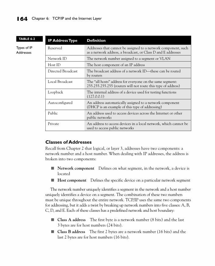
Types of AddressesMany different types of IP addresses exist. Table 6-2 offers a brief description of these types.
IP uses a TTL field to limit the number of hops a datagram can travel. This is discussed in more depth in Chapters 15 and 19. Here are some
common IP protocols and their protocol numbers: ICMP (1), IPv6 (41), TCP (6), UDP (17), Enhanced Interior Gateway Routing Protocol (EIGRP) (88), and OSPF (89).
ch06.indd 163 3/20/08 2:55:53 PM
164 Chapter 6: TCP/IP and the Internet Layer
CertPrs8/CCNA® Cisco Certified Network Associate Study Guide/Richard Deal/149728-5/Chapter 6
Classes of AddressesRecall from Chapter 2 that logical, or layer 3, addresses have two components: a network number and a host number. When dealing with IP addresses, the address is broken into two components:
■ Network component Defines on what segment, in the network, a device is located
■ Host component Defines the specific device on a particular network segment
The network number uniquely identifies a segment in the network and a host number uniquely identifies a device on a segment. The combination of these two numbers must be unique throughout the entire network. TCP/IP uses the same two components for addressing, but it adds a twist by breaking up network numbers into five classes: A, B, C, D, and E. Each of these classes has a predefined network and host boundary:
■ Class A address The first byte is a network number (8 bits) and the last 3 bytes are for host numbers (24 bits).
■ Class B address The first 2 bytes are a network number (16 bits) and the last 2 bytes are for host numbers (16 bits).
IP Address Type Definition
Reserved Addresses that cannot be assigned to a network component, such as a network address, a broadcast, or Class D and E addresses
Network ID The network number assigned to a segment or VLAN
Host ID The host component of an IP address
Directed Broadcast The broadcast address of a network ID—these can be routed by routers
Local Broadcast The “all hosts” address for everyone on the same segment: 255.255.255.255 (routers will not route this type of address)
Loopback The internal address of a device used for testing functions (127.0.0.1)
Autoconfigured An address automatically assigned to a network component (DHCP is an example of this type of addressing)
Public An address used to access devices across the Internet or other public networks
Private An address to access devices in a local network, which cannot be used to access public networks
TABLE 6-2
Types of IP Addresses
ch06.indd 164 3/20/08 2:55:53 PM

TCP/IP Protocol Stack 165
CertPrs8/CCNA® Cisco Certified Network Associate Study Guide/Richard Deal/149728-5/Chapter 6
■ Class C address The first 3 bytes are a network number (24 bits) and the last 1 byte is for host numbers (8 bits).
■ Class D and E addresses Used for multicasting and Class E addresses are reserved.
Given the distinctions discussed so far, it would seem that addressing for IPv4 is easy. However, what distinguishes the different classes of addresses are the settings to which the first bit to 5 bits are set:
■ Class A addresses always begin with a 0 in the highest order bit.
■ Class B addresses always begin with 10 in the highest order bits.
■ Class C addresses always begin with 110 in the highest order bits.
■ Class D addresses always begin with 1110 in the highest order bits.
■ Class E addresses always begin with 11110 in the highest order bits.
When talking about the highest order bit or bits, this includes all 32 bits. Therefore, this would be the very first bit on the left of the address (the most significant bit). If the first octet contains 1000001, this represents 129 in decimal, which would be a Class B address.
Given these distinctions with the assigned high order bit values, it is easy to predict, for a given address, to what class of network numbers it belongs:
■ Class A addresses range from 1 to 126: 0 is reserved and represents all IP addresses; 127 is a reserved address and is used for testing, such as a loopback on an interface.
■ Class B addresses range from 128 to 191: binary 10000000-10111111.
■ Class C addresses range from 192 to 223: binary 11000000-11011111.
■ Class D addresses range from 224 to 239: binary 11100000-11101111.
■ Class E addresses range from 240 to 254: 255 is a reserved address and is used for local broadcasting purposes.
Remember the five classes of IP addresses, and the fact that Class A
addresses have, by default, 8 network bits, Class B 16 bits, and Class C 24 bits.
ch06.indd 165 3/20/08 2:55:54 PM

166 Chapter 6: TCP/IP and the Internet Layer
CertPrs8/CCNA® Cisco Certified Network Associate Study Guide/Richard Deal/149728-5/Chapter 6
Given these restrictions with beginning bit values, it is fairly easy to predict what address belongs to what class. Simply look at the first number in the dotted-decimal notation and see which range it falls into.
When you are dealing with IP addresses, two numbers are always reserved for each network number: the first address in the network represents the network’s address, and the last address in the network represents the broadcast address for this network, commonly called a directed broadcast. When you look at IP itself, two IP addresses are reserved: 0.0.0.0 (the very first address), which represents all IP addresses, and 255.255.255.255 (the very last address), which is the local broadcast address (all devices should process this datagram). Don’t get too worried at this point if this is confusing, because Chapter 7 will delve into IPv4 addressing in a lot of depth.
Public and Private AddressesAs to assigning addresses to devices, two general types of addresses can be used: public and private. Public addresses are Class A, B, and C addresses that can be used to access devices in other public networks, such as the Internet. The Internet Assigned Numbers Authority (IANA) is ultimately responsible for handing out and managing public addresses. Normally you get public addresses directly from your ISP, which, in turn, requests them from one of five upstream address registries:
■ American Registry for Internet Numbers (ARIN)
■ Reseaux IP Europeans Network Coordination Center (RIPE NCC)
■ Asia Pacific Registry for Internet Numbers (APNIC)
■ Latin American and Caribbean Internet Address Registry (LACNIC)
■ African Network Information Centre (AfriNIC)
Class A addresses range from 1 to 126, Class B from 128 to 191, Class C from 192 to 223, Class D from 224 to 239, and Class E from 240 to 254. 127 is reserved for the loopback interface (internal testing). Also remember the ranges
in binary. Remember the binary values that IP addresses begin with, and you should be able to determine, by looking at the first binary byte, whether the address is a Class A, B, C, D, or E address.
ch06.indd 166 3/20/08 2:55:54 PM

TCP/IP Protocol Stack 167
CertPrs8/CCNA® Cisco Certified Network Associate Study Guide/Richard Deal/149728-5/Chapter 6
Within this range of addresses for Class A, B, and C addresses are some reserved addresses, commonly called private addresses. All the other addresses in these classes are called public addresses. Anyone can use private addresses; however, this creates a problem if you want to access the Internet. Remember that each device in the network (in this case, this includes the Internet) must have a unique IP address. If two networks are using the same private addresses, you would run into reachability issues. To access the Internet, your source IP addresses must have a unique Internet public address. This can be accomplished through address translation. Here is a list of private addresses that are assigned in RFC 1918:
■ Class A: 10.0.0.0–10.255.255.255 (1 Class A network)
■ Class B: 172.16.0.0–172.31.255.255 (16 Class B networks)
■ Class C: 192.168.0.0–192.168.255.255 (256 Class C networks)
Private and public addresses, as well as address translation, are discussed in Chapter 23.
DNSOne of the problems with using IP addresses to access destinations is that as a person, it can be difficult to remember dozens of addresses of devices. People tend to be better at remembering names than lists of dotted-decimal numbers. However, since network components are uniquely identified by IP addresses, something is needed to translate names to addresses, which is what the Domain Name System (DNS) does. DNS is used to resolve names to IP addresses. DNS is a TCP/IP application that other applications such as File Transfer Protocol (FTP) applications, telnet, web browsers, and e-mail use to resolve the names a user enters to real IP addresses.
To use DNS, a network component needs to define a DNS server that will handle the resolution process. Most components, such as Windows PCs, allow two DNS servers to be configured for redundancy. You can manually define the DNS servers to use or acquire them dynamically via Dynamic Host Configuration Protocol (DHCP, discussed a bit later).
Remember the list of private networks, which must be translated when accessing public networks: 10.0.0.0,
172.16.0.0–172.31.0.0, and 192.168.0.0–192.168.255.0.
ch06.indd 167 3/20/08 2:55:54 PM

168 Chapter 6: TCP/IP and the Internet Layer
CertPrs8/CCNA® Cisco Certified Network Associate Study Guide/Richard Deal/149728-5/Chapter 6
CERTIFICATION OBJECTIVE 6.02
TCP/IP Internet ProtocolsMany, many protocols function at the Internet layer. If you go out to IANA’s web site, you’ll see more than 100 protocols defined for the Internet layer. The most commonly used of these protocols is IP, which is used to transport data for these other protocols. This part of the chapter will discuss some of the more common ones: Dynamic Host Configuration Protocol (DHCP), Address Resolution Protocol (ARP), and Internet Control Message Protocol (ICMP).
DHCPDHCP allows devices to acquire their addressing information dynamically. Originally defined in RFC 2131 and updated in 2939, DHCP is actually based on the Bootstrap Protocol (BOOTP). It is built on a client/server model and defines two components:
■ Server Delivering host configuration information
■ Client Requesting and acquiring host configuration information
DHCP provides the following advantages:
■ It reduces the amount of configuration on devices.
■ It reduces the likelihood of configuration errors on devices acquiring address information.
■ It gives you more administrative control by centralizing IP addressing information and management.
Most networks today employ DHCP because it is easy to implement and manage. Imagine you work for a company that is bought by another company and you must re-address your network, which contains 2000 devices. If you previously configured the IP
addresses on these machines manually, then you now must manually change each device’s configuration. However, if you were using DHCP, you have to change the
Remember the advantages that DHCP provides.
ch06.indd 168 3/20/08 2:55:55 PM

TCP/IP Internet Protocols 169
CertPrs8/CCNA® Cisco Certified Network Associate Study Guide/Richard Deal/149728-5/Chapter 6
configuration on only the DHCP servers, and when the clients either reboot or must renew their addressing information, they’ll acquire the addressing information from the new addressing scheme.
As mentioned, DHCP contains two types of devices: servers and clients. Cisco IOS routers support both functions. Servers are responsible for assigning addressing information to clients, and clients request addressing information from servers. A DHCP server can use three mechanisms, which are described in Table 6-3, when allocating address information. Most DHCP implementations use the dynamic allocation type.
When acquiring addressing information, a DHCP client goes through four steps:
1. A client generates a DHCPDISCOVER local broadcast to discover who the DHCP servers are on the LAN segment.
2. All DHCP servers on the segment can respond to the client with a DHCPOFFER unicast message, which offers IP addressing information to the client. If a client receives messages from multiple servers, it chooses one (typically the first one). DHCPOFFER server messages include the following information: IP address of the client, subnet mask of the segment, IP address of the default gateway, DNS domain name, DNS server address or addresses, WINS server address or addresses, and TFTP server address or addresses. Note that this is not an all-encompassing list.
3. Upon choosing one of the offers, the client responds to the corresponding server with a DHCPREQUEST message, telling the server that it wants to use the addressing information the server sent. If only one server is available and the server’s information conflicts with the client’s configuration, the client will respond with a DHCPDECLINE message.
Allocation Type Explanation
Automatic Server assigns a permanent IP address to the client
Dynamic Server assigns an IP address to a client for a period of time, referred to as a lease
Manual IP address is manually configured on the client, and DHCP is used to convey additional addressing information and verification
TABLE 6-3
DHCP Address Allocation Types
ch06.indd 169 3/20/08 2:55:55 PM

170 Chapter 6: TCP/IP and the Internet Layer
CertPrs8/CCNA® Cisco Certified Network Associate Study Guide/Richard Deal/149728-5/Chapter 6
4. The DHCP server responds with a DHCPACK, which is an acknowledgment to the client indicating that it received the DHCPREQUEST message and that the client accepted the addressing information. The server can also re-spond with a DHCPNACK, which tells the client the offer is no longer valid and the client should request addressing information again. This can happen if the client is tardy in responding with a DHCPREQUEST message after the server generated the DHCPOFFER message.
When a client shuts down gracefully, it can generate a DHCPRELEASE message, telling the server it no longer needs its assigned IP address. Most DHCP configurations involve a lease time, which specifies a time period that the client is allowed to use the address. Upon reaching this time limit, the client must renew its lease with the current server or get new IP addressing information.
If a server does not respond to the client, the client’s TCP/IP protocol stack will automatically pick an IP address from the range of this Class B network: 169.254.0.1–169.254.255.254, based on the RFC. This process is referred to as Automatic Private IP Addressing (APIP). However, I know of only Microsoft Windows operating systems that perform APIP; other operating systems, such as Linux, won’t enable the NIC if they can’t obtain IP addressing for the NIC.
ARPThe Address Resolution Protocol (ARP) is an Internet layer protocol that helps TCP/IP network components find other devices in the same broadcast domain. ARP uses a local broadcast (255.255.255.255) at layer 3 and FF:FF:FF:FF:FF:FF at layer 2 to discover neighboring devices. Basically stated, you have the IP address you want to reach, but you need a physical (MAC) address to send the frame to the destination at layer 2. ARP resolves an IP address of a destination to the MAC
Remember the four steps that DHCP goes through when a client requests addressing information as well as the information that can be included
in a DHCPOFFER message: an IP address and a subnet mask; a default gateway; DNS server, TFTP server, and WINS server addresses; and a domain name.
ch06.indd 170 3/20/08 2:55:55 PM

TCP/IP Internet Protocols 171
CertPrs8/CCNA® Cisco Certified Network Associate Study Guide/Richard Deal/149728-5/Chapter 6
address of the destination on the same data link layer medium, such as Ethernet. Remember that for two devices to talk to each other in Ethernet (as with most layer 2 technologies), the data link layer uses a physical address (MAC) to differentiate the machines on the segment. When Ethernet devices talk to each other at the data link layer, they need to know each other’s MAC addresses.
Single-Segment ARP ExampleThe top part of Figure 6-2 shows an example of the use of ARP. In this example PC-A wants to send information directly to PC-B. PC-A knows PC-B’s IP address (or has DNS resolve it to an IP address); however, it doesn’t know PC-B’s Ethernet MAC address. To resolve the IP to a MAC address, PC-A generates an ARP request. In the ARP datagram, the source IP address is 10.1.1.1 and the destination is 255.255.255.255 (the local broadcast represents every device on the
FIGURE 6-2
ARP and RARP examples
ch06.indd 171 3/20/08 2:55:56 PM

172 Chapter 6: TCP/IP and the Internet Layer
CertPrs8/CCNA® Cisco Certified Network Associate Study Guide/Richard Deal/149728-5/Chapter 6
Ethernet segment). PC-A includes PC-B’s IP address in the data field of the ARP datagram. This is encapsulated into an Ethernet frame, with a source MAC address of 0000.0CCC.1111 (PC-A’s MAC address) and a destination MAC address of FF:FF:FF:FF:FF:FF (the local broadcast address) and is then placed on the Ethernet segment. Both PC-B and PC-C see this frame. Both devices’ NICs notice the data link layer broadcast address and assume that this frame is for them since the destination MAC address is a broadcast, so they strip off the Ethernet frame and pass the IP datagram with the ARP request up to the Internet layer. Again, there is a broadcast address in the destination IP address field, so both devices’ TCP/IP protocol stacks will examine the data payload. PC-B notices that this is an ARP and that this is its own IP address in the query, and therefore responds directly back to PC-A with PC-B’s MAC address. PC-C, however, sees that this is not an ARP for its MAC address and ignores the datagram.
One important thing that both PC-B and PC-C will do is add PC-A’s MAC address to their local ARP tables. They do this so that if either device needs to communicate with PC-A, neither will have to perform the ARP request as PC-A had to. Entries in the ARP table will time out after a period of non-use of the MAC address. This time period is dependent on the operating system used, but it can typically be changed by the user or administrator. Also, a device can generate what is called a gratuitous ARP. A gratuitous ARP is an ARP reply that is generated without a corresponding ARP request. This is commonly used when a device might change its IP address or MAC address and wants to notify all other devices on the segment about the change so that the other devices have the correct information in their local ARP tables.
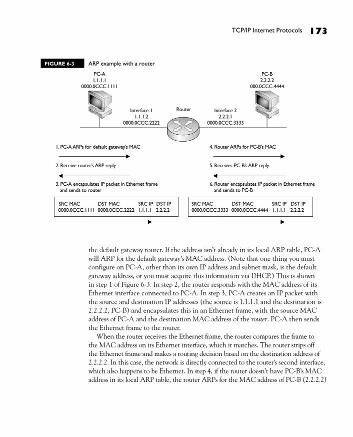
Two-Segment ARP ExampleFigure 6-3 shows a more detailed example of the use of ARP. In this example, PC-A wants to connect to PC-B using IP. The source address is 1.1.1.1 (PC-A) and the destination is 2.2.2.2 (PC-B). Since the two devices are on different networks, a router is used to communicate between the networks. Therefore, if PC-A wants to send something to PC-B, it has to be sent via the intermediate router. However, this communication does not occur at the network layer using IP; instead, it occurs at the data link layer.
Assume that Ethernet is being used in this example. The first thing that PC-A will do is to determine whether the destination, based on the layer 3 address, is local to this subnet or on another subnet. (This process is discussed in Chapter 7.) In this example, it’s a remote location, so PC-A will need to know the MAC address of
ch06.indd 172 3/20/08 2:55:57 PM
TCP/IP Internet Protocols 173
CertPrs8/CCNA® Cisco Certified Network Associate Study Guide/Richard Deal/149728-5/Chapter 6
the default gateway router. If the address isn’t already in its local ARP table, PC-A will ARP for the default gateway’s MAC address. (Note that one thing you must configure on PC-A, other than its own IP address and subnet mask, is the default gateway address, or you must acquire this information via DHCP.) This is shown in step 1 of Figure 6-3. In step 2, the router responds with the MAC address of its Ethernet interface connected to PC-A. In step 3, PC-A creates an IP packet with the source and destination IP addresses (the source is 1.1.1.1 and the destination is 2.2.2.2, PC-B) and encapsulates this in an Ethernet frame, with the source MAC address of PC-A and the destination MAC address of the router. PC-A then sends the Ethernet frame to the router.
When the router receives the Ethernet frame, the router compares the frame to the MAC address on its Ethernet interface, which it matches. The router strips off the Ethernet frame and makes a routing decision based on the destination address of 2.2.2.2. In this case, the network is directly connected to the router’s second interface, which also happens to be Ethernet. In step 4, if the router doesn’t have PC-B’s MAC address in its local ARP table, the router ARPs for the MAC address of PC-B (2.2.2.2)
FIGURE 6-3 ARP example with a router
ch06.indd 173 3/20/08 2:55:59 PM

174 Chapter 6: TCP/IP and the Internet Layer
CertPrs8/CCNA® Cisco Certified Network Associate Study Guide/Richard Deal/149728-5/Chapter 6
and receives the response in step 5. The router then encapsulates the original IP packet in a new Ethernet frame in step 6, placing its second interface’s MAC address, which is sourcing the frame, in the source MAC address field and PC-B’s MAC address in the destination field. When PC-B receives this, it knows the frame is for itself (matching destination MAC address) and that PC-A originated the IP packet that’s encapsulated based on the source IP address in the IP header at layer 3.
Note that in this example, the original IP addressing in the packet was not altered by the router, but two Ethernet frames are used to get the IP packet to the destination. Also, each device will keep the MAC addresses in a local ARP table, so the next time PC-A needs to send something to PC-B, the devices will not have to ARP other intermediate devices again.
The assumption with ARP is that the device being ARPed is on the same segment. For example, in Figure 6-4, PC-A assumes 1.1.1.2 (the router’s IP address) is in the same broadcast domain based on the IP address of the router, which is true. If PC-A generated a broadcast ARP for the router’s MAC address, the router would see the request. However, you might encounter a situation in which you’ve moved a device from one part of the network to another, but you must keep the device’s original IP address when moving it.
If you examine Figure 6-4, you can see that PC-C was moved from the left-hand segment to the right-hand segment, but its IP address was kept the same.
Be familiar with what device talks to what other device at both layer 2 and layer 3. With a router between the source and destination, the source at layer 2 uses its own MAC address as
the source but the default gateway MAC address as the destination. Note that the IP addresses used at layer 3 are not changed by the router.
Proxy ARP allows the router to respond with its own MAC address in an ARP reply for a device on a different network segment. Proxy ARP is used when
you need to move a device from one segment to another but cannot change its current IP addressing information.
ch06.indd 174 3/20/08 2:56:00 PM

TCP/IP Internet Protocols 175
CertPrs8/CCNA® Cisco Certified Network Associate Study Guide/Richard Deal/149728-5/Chapter 6
However, PC-A still assumes that PC-C is on the local segment. To solve this reachability problem, two things need to occur:
■ The router will need a static host route that directs traffic sent to the host address that was moved to the devices’ new network segment.
■ The proxy ARP must be enabled on the router’s interface that’s connected to the original network segment.
Proxy ARP is a feature that allows a router to reply with its own MAC address to an ARP query when the destination device isn’t on the same segment. For example, in Figure 6-4, since PC-C won’t see the local broadcast ARP query from PC-A, and the router has a static host route for 1.1.1.3 that points to the right-hand segment, when the router receives the ARP request for 1.1.1.3, the router will respond with its own MAC address (0000.0CCC.2222). This creates the illusion for PC-A that PC-C is still on the same segment. PC-A will then forward its traffic to the router (thinking that it is actually sending it directly to PC-C), and the router will then route the traffic to the correct network segment.
The example shown in Figure 6-4 is not a recommended practice in a network: if you move a device from one segment to another, you should change its IP addressing information to match the network number of the new segment. The only two times that you might need Proxy ARP are if an application has hard-coded the IP address and therefore you can’t change it when moving the server to a different network number; and in certain cases with assigning of IP addressing information to remote access IPSec clients.
PC-C1.1.1.3
0000.0CCC.5555
Interface 11.1.1.2
0000.0CCC.2222
Interface 22.2.2.1
0000.0CCC.3333
PC-A1.1.1.1
0000.0CCC.1111
PC-B2.2.2.2
0000.0CCC.4444
Router
FIGURE 6-4
Proxy ARP example
ch06.indd 175 3/20/08 2:56:02 PM

176 Chapter 6: TCP/IP and the Internet Layer
CertPrs8/CCNA® Cisco Certified Network Associate Study Guide/Richard Deal/149728-5/Chapter 6
RARPRARP is sort of the reverse of an ARP. In an ARP, the device knows the layer 3 address, but not the data link layer address. With a RARP, the device doesn’t have an IP address and wants to acquire one. The only address that this device has is a MAC address. Common protocols that use RARP are BOOTP and DHCP.
The bottom part of Figure 6-2 shows a RARP example. In this example, PC-D doesn’t have an IP address and wants to acquire one. It generates a data link layer broadcast (FF:FF:FF:FF:FF:FF) with an encapsulated RARP request. This example assumes that the RARP is associated with BOOTP. If there is a BOOTP server on the segment, and if it has an IP address for this machine, it will respond. In this example, the BOOTP server, 10.1.1.5, has an address (10.1.1.4) and assigns this to PC-D, sending this address as a response to PC-D.
ICMPICMP is used to send error and control information between TCP/IP devices at the Internet layer. ICMP, originally defined in RFC 792, includes many different messages that devices can generate or respond to. Here is a brief list of these messages: Address Reply, Address Request, Destination Unreachable, Echo, Echo Reply, Information Reply, Information Request, Parameter Problem, Redirect, Subnet Mask Request, Time Exceeded, Timestamp, and Timestamp Reply.
One of the most common applications that uses ICMP is ping. Ping uses a few ICMP messages, including echo, echo request, destination unreachable, and others. Ping is used to test whether or not a destination is available. A source generates an ICMP echo packet. If the destination is available, it will respond with an echo reply packet. If an intermediate router doesn’t know how to reach the destination, it will respond with a destination unreachable message. However, if the router knows how to reach the destination, but the destination host doesn’t respond to the echo packets, you’ll see a request timed out message. Traceroute, sometimes called trace, is an application that will list the IP addresses of the routers along the way to the destination, displaying the path the packet took to reach the destination. Some traceroute applications use ICMP messages, while others use UDP to transport their messages. These tools are discussed in more depth in the next section, as well as in Chapter 17.
Two common applications that use ICMP are ping and traceroute.
Ping uses an ICMP echo message to test connectivity to a remote device.
ch06.indd 176 3/20/08 2:56:03 PM

TCP/IP Tools for Windows PCs 177
CertPrs8/CCNA® Cisco Certified Network Associate Study Guide/Richard Deal/149728-5/Chapter 6
CERTIFICATION OBJECTIVE 6.03
TCP/IP Tools for Windows PCsYou can use various tools on a device to check its IP configuration, as well as to test connectivity to and between devices. This part of the book will focus on tools you can use on a Windows-based PC: ipconfig, ping, tracert, and arp.
ipconfig CommandThe ipconfig command is a CLI tool that displays your PC’s IP configuration. To execute the command, you must open up a command window: Go to Start | Run, and enter cmd.exe in the Open text box. Then click the OK button. To see all of the optional parameters available to you, execute ipconfig /all from the CLI. The available options are shown in Table 6-4.
Option Description
/all Displays the complete TCP/IP configuration for all adapters in the PC; omitting this parameter displays only the IP address, subnet mask, and default gateway setting for each adapter.
/renew [adapter] Renews a DHCP acquired address for all adapters or the specified adapter.
/release [adapter]
Has the PC send a DHCPRELEASE message to the DHCP server indicating that the PC is no longer using the address; it also causes the PC to disable the use of DHCP to acquire addressing information.
/flushdns Flushes the PC’s DNS cache of resolves names and addresses.
/displaydns Displays the PC’s local DNS cache of resolved names and addresses.
/registerdns Initiates dynamic DNS, having the PC publish its name and IP address to a DNS server. This is commonly used when PCs are acquiring their IP addresses dynamically via DNS, where their addresses can differ over time, but the PC’s name remains the same.
/showclassid [adapter]
Displays the DHCP class ID.
/setclassid [adapter [classID]]
Sets the DHCP class ID value to be used, which can be sent to a DHCP server to help it in assigning the right addressing information to the PC.
TABLE 6-4 ipconfig Command Options
ch06.indd 177 3/20/08 2:56:04 PM

178 Chapter 6: TCP/IP and the Internet Layer
CertPrs8/CCNA® Cisco Certified Network Associate Study Guide/Richard Deal/149728-5/Chapter 6
Here is an example using the /all parameter:
C:\> ipconfig /all Windows IP Configuration Host Name . . . . . . . . . . . . : D620 Primary Dns Suffix . . . . . . . : Node Type . . . . . . . . . . . . : Hybrid IP Routing Enabled. . . . . . . . : No WINS Proxy Enabled. . . . . . . . : No Ethernet adapter Wireless: Connection-specific DNS Suffix . : Description . . . . . . . . . . . : Intel(R) PRO/Wireless 3945ABG Network Connection Physical Address. . . . . . . . . : 00-18-DE-8A-52-A6 Dhcp Enabled. . . . . . . . . . . : No IP Address. . . . . . . . . . . . : 192.168.1.66 Subnet Mask . . . . . . . . . . . : 255.255.255.0 Default Gateway . . . . . . . . . : 192.168.1.1 DNS Servers . . . . . . . . . . . : 4.2.2.1 4.2.2.2
Notice that in this example, the IP addressing information has been manually configured on the PC for the wireless adapter—DHCP is not being used to acquire addressing information. If DHCP were used, you would also see when the address was obtained and when the lease would expire for the IP addressing information.
ipconfig is used for Windows NT machines and later; Windows 98 and earlier machines use the winipcfg command.
In addition to using the ipconfig CLI command, you can also view information about the configuration of an adapter from the Network Connection tab in Windows. In Windows XP, to pull up this window, choose Start | Connect To | Show All Connections. Double-click the name of an adapter in the Network Connections window and then click the Properties button. Click Internet Protocol (TCP/IP) and then click the Properties button. If the radio buttons Obtain An IP Address Automatically and Obtain DNS Server Address Automatically are selected, DHCP will be used to acquire the IP addressing information for the adapter.
ch06.indd 178 3/20/08 2:56:04 PM

TCP/IP Tools for Windows PCs 179
CertPrs8/CCNA® Cisco Certified Network Associate Study Guide/Richard Deal/149728-5/Chapter 6
CompTIA recommends that you systematically test connectivity by pinging from local to remote networks or destinations.
The ping CommandThe Windows ping command is used to test layer 3 connectivity between two devices. The source sends an ICMP echo message and if the destination is reachable, it replies with an ICMP echo reply message. If the destination is not reachable and an intermediate router is between the source and destination, the router closest to the problem will send back an appropriate ICMP message. If the router is connected to the same segment as the destination device and the destination device is not reachable, the router will respond with an ICMP destination host unreachable message; otherwise, if the router doesn’t have a route to the destination network, it will reply with an ICMP destination network unreachable message.
Ping uses ICMP echo messages to initiate the test. If the destination is reachable, the destination responds with an echo reply message
for each echo sent by the source. Both the Windows PC ping and tracert commands test layer 3 connectivity.
ch06.indd 179 3/20/08 2:56:04 PM

180 Chapter 6: TCP/IP and the Internet Layer
CertPrs8/CCNA® Cisco Certified Network Associate Study Guide/Richard Deal/149728-5/Chapter 6
The Windows ping command is executed from the CLI command prompt. Table 6-5 lists the more common options you can specify with the command.
Here is an example of using the ping command:
C:\ > ping 4.2.2.2 Pinging 4.2.2.2 with 32 bytes of data: Request timed out. Reply from 4.2.2.2: bytes=32 time=20ms TTL=53 Reply from 4.2.2.2: bytes=32 time=22ms TTL=53 Reply from 4.2.2.2: bytes=32 time=20ms TTL=53
Option Description
-t Sends a continuous string of echo request messages to the destination: use CTRL-C to abort the process.
-a Performs a reverse name lookup, resolving the entered IP address to a fully qualified domain name.
-n count Sends the specified number of echo request messages; if you omit this parameter, the default is 4 echo requests.
-l size Specifies the size, in bytes, of the echo request message; if you omit this parameter, the default is 32 bytes.
-f Sets the don’t fragment flag in the IP header.
-w seconds Specifies the number of seconds to wait for an echo reply message before giving up on the reply; if you omit this parameter, the default is 2 seconds.
TABLE 6-5
Windows ping Command Options
When troubleshooting PC problems, first determine whether the user can ping the loopback address: ping 127.0.0.1. If this fails, then something is wrong with the TCP/IP stack installation on the PC. Next, have the user try to ping the locally configured IP address.
If this fails, something is wrong with the IP address configuration on the PC. Next, have the user ping the default gateway. If this fails, then something is wrong with the configured default gateway address, the default gateway itself, or the subnet mask value configured on the user’s PC.
ch06.indd 180 3/20/08 2:56:05 PM

TCP/IP Tools for Windows PCs 181
CertPrs8/CCNA® Cisco Certified Network Associate Study Guide/Richard Deal/149728-5/Chapter 6
Ping statistics for 4.2.2.2: Packets: Sent = 4, Received = 3, Lost = 1 (25% loss), Approximate round trip times in milli-seconds: Minimum = 20ms, Maximum = 25ms, Average = 21ms
Notice that the first echo request message timed out, but the following three were successful—this is probably because this PC, as well as intermediate routers, had to perform ARPs to find the next hop layer 3 device’s MAC address, causing the time to exceed 2 seconds. In the successful echo replies, you can see the time it took for the round-trip between the source and destination; for example, the last echo request and reply took 20 milliseconds to complete.
The tracert CommandOne limitation of ping is that this command will not tell you, between you and the destination device, where layer 3 connectivity is broken. The Windows tracert command (short for traceroute), on the other hand, will list each router along the way, including the final destination. Therefore, if a layer 3 connection problem exists, with traceroute, you’ll know at least where the problem begins. Table 6-6 lists the more common options you can specify with the tracert command.
If the first echo request times out, but the rest of the echo requests are successful, the first request probably timed out because the source and possibly intermediate devices were performing ARPs. If you see intermixed echo replies and destination unreachable messages,
you know that either a lot of traffic lies between you and the destination, causing a large delay in the returning echo replies, or a physical layer problem exists somewhere between the source and destination causing corruption of sent data.
Option Explanation
-d Specifies that a reverse DNS lookup should not be performed for each hop to, and including, the destination
-h maximum_hops Specifies the maximum number of hops that the trace can traverse to the destination
-w timeout Specifies the number of seconds to wait for an echo reply message before giving up on the reply; if you omit this parameter, the default is 2 seconds
TABLE 6-6
Windows tracert Command Options
ch06.indd 181 3/20/08 2:56:05 PM

182 Chapter 6: TCP/IP and the Internet Layer
CertPrs8/CCNA® Cisco Certified Network Associate Study Guide/Richard Deal/149728-5/Chapter 6
Here is an example of the use of the tracert command:
C:\ > tracert -d 4.2.2.2 Tracing route to 4.2.2.2 over a maximum of 30 hops 1 1 ms 1 ms 1 ms 192.168.1.1 2 8 ms 7 ms 9 ms 10.122.208.1 3 10 ms 20 ms 12 ms 24.95.231.65 . . . 8 27 ms 26 ms 20 ms 4.68.103.68 9 21 ms 20 ms 24 ms 4.2.2.2 Trace complete.
In this example, it took nine hops to reach the destination (4.2.2.2). Three probes were sent to each next-hop layer 3 device, which the round-trip time, in milliseconds, displayed for each probe. If you see an asterisk (*) for the probe reply, either the traceroute probe message reply came back after the timeout period or it didn’t come back at all.
I highly recommend that you use the -d parameter when executing the tracert command; this disables the reverse DNS lookup to find the name of each layer 3 device along the way to the destination. If you don’t use this option, your trace will take much longer to finish.
The arp CommandThe Windows arp command allows you to display the ARP table, delete entries in it, or add static entries to it. The more common parameters to the command are shown in Table 6-7.
Option Description
-a or –g Displays the entries in the ARP table.
-d [inet_addr] Deletes all the entries in the ARP table unless a specific IP address is entered.
-s inet_addr eth_addr Adds a static ARP entry, where you need to specify the IP and MAC addresses, in that order, of the destination device. This is normally not configured unless for security purposes.
TABLE 6-7
Windows arp Command Options
ch06.indd 182 3/20/08 2:56:05 PM
TCP/IP Tools for Windows PCs 183
CertPrs8/CCNA® Cisco Certified Network Associate Study Guide/Richard Deal/149728-5/Chapter 6
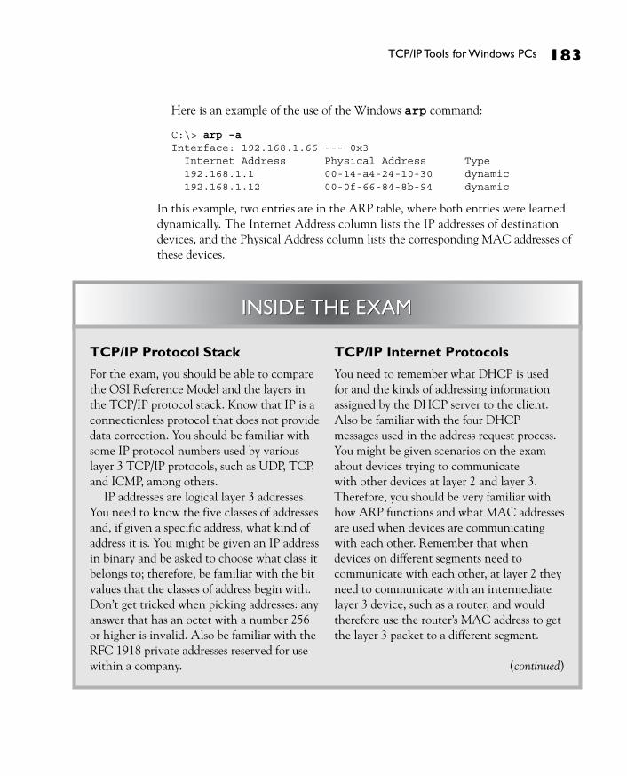
Here is an example of the use of the Windows arp command:
C:\> arp –a Interface: 192.168.1.66 --- 0x3 Internet Address Physical Address Type 192.168.1.1 00-14-a4-24-10-30 dynamic 192.168.1.12 00-0f-66-84-8b-94 dynamic
In this example, two entries are in the ARP table, where both entries were learned dynamically. The Internet Address column lists the IP addresses of destination devices, and the Physical Address column lists the corresponding MAC addresses of these devices.
INSIDE THE EXAM
TCP/IP Protocol Stack
For the exam, you should be able to compare the OSI Reference Model and the layers in the TCP/IP protocol stack. Know that IP is a connectionless protocol that does not provide data correction. You should be familiar with some IP protocol numbers used by various layer 3 TCP/IP protocols, such as UDP, TCP, and ICMP, among others.
IP addresses are logical layer 3 addresses. You need to know the five classes of addresses and, if given a specific address, what kind of address it is. You might be given an IP address in binary and be asked to choose what class it belongs to; therefore, be familiar with the bit values that the classes of address begin with. Don’t get tricked when picking addresses: any answer that has an octet with a number 256 or higher is invalid. Also be familiar with the RFC 1918 private addresses reserved for use within a company.
TCP/IP Internet Protocols
You need to remember what DHCP is used for and the kinds of addressing information assigned by the DHCP server to the client. Also be familiar with the four DHCP messages used in the address request process. You might be given scenarios on the exam about devices trying to communicate with other devices at layer 2 and layer 3. Therefore, you should be very familiar with how ARP functions and what MAC addresses are used when devices are communicating with each other. Remember that when devices on different segments need to communicate with each other, at layer 2 they need to communicate with an intermediate layer 3 device, such as a router, and would therefore use the router’s MAC address to get the layer 3 packet to a different segment.
(continued)
INSIDE THE EXAM
ch06.indd 183 3/20/08 2:56:06 PM
184 Chapter 6: TCP/IP and the Internet Layer
CertPrs8/CCNA® Cisco Certified Network Associate Study Guide/Richard Deal/149728-5/Chapter 6
CERTIFICATION SUMMARYTCP/IP has four layers: application, transport, internet, and network access. IP functions at the Internet layer and transports protocols such as ICMP, ARP, RARP, OSPF, EIGRP, and others. ICMP is used to test connections. IP provides a best effort, connectionless delivery of datagrams with no data recovery capabilities. Through hierarchical addressing, IP can scale networks to very large sizes.
IP addresses are 32 bits in length and are broken up into 4 bytes, with a period between the bytes. This format is referred to as dotted decimal. There are five classes of IP addresses: A (1–126), B (128–191), C (192–223), D (224–239), and E (240–254). Class A, B, and C addresses have two components, network and host, where the combination of these components must be unique in the network. Class A addresses have 1 network byte and 3 host bytes. Class B addresses have 2 network and 2 host bytes. Class C addresses have 3 network bytes and 1 host byte. Private IP addresses include networks 10.0.0.0, 172.16.0.0–172.31.0.0, and 192.168.0.0–192.168.255.0. Address 127.0.0.0 is reserved for loopback functions on devices to perform local testing. To make dealing with IP addresses easier, names can be used to access remote devices instead of addresses; in this instance, DNS will resolve the name to its corresponding IP address.
ICMP is commonly used to test connectivity at layer 3. If you receive a destination unreachable message, an intermediate layer 3 device is indicating that either no path exists to the destination or the destination itself is not reachable. Traceroute is used to determine where a layer 3 problem exists between two devices.
TCP/IP Tools for Windows PCs
You need to be familiar with the Windows commands to troubleshoot connectivity, especially ping. Remember that pinging 127.0.0.1 tests whether or not the TCP/IP protocol stack has or hasn’t been installed successfully on a local device. Also remember the different scenarios as to when you might see “request timeout”: ARPs, physical layer problems, and/or delay issues.
ch06.indd 184 3/20/08 2:56:06 PM

Certifi cation Summary 185
CertPrs8/CCNA® Cisco Certified Network Associate Study Guide/Richard Deal/149728-5/Chapter 6
DHCP is used to assign addressing information dynamically to devices. This can include an IP address, a subnet mask, a default gateway address, two DNS server addresses, two WINS server addresses, a TFTP server address, and the length of the lease. ARP resolves an IP address to a MAC address. RARP, used by BOOTP and DHCP, resolves a MAC address to an IP address (used to acquire IP addressing information on a device). ICMP is used to send control and error information between devices. The most common application that uses ICMP is ping, which is used to test connectivity between devices. Common Windows commands to troubleshoot layer 3 connectivity include ipconfig, ping, tracert, and arp.
ch06.indd 185 3/20/08 2:56:06 PM

186 Chapter 6: TCP/IP and the Internet Layer
CertPrs8/CCNA® Cisco Certified Network Associate Study Guide/Richard Deal/149728-5/Chapter 6
TWO-MINUTE DRILLTCP/IP Protocol Stack
❑ The TCP/IP protocol stack has the following four layers: network access, internet, transport, and application.
❑ The Internet layer corresponds to the network layer of the OSI Reference Model, where the IP protocol resides.
❑ IP provides connectionless, best effort delivery of datagrams.
❑ Common TCP/IP protocols include IP, ICMP, TCP, UDP, EIGRP, and OSPF.
❑ The TTL field in the IP header is used to restrict the maximum number of hops a datagram can travel.
❑ IP addresses are 32 bits in length and are broken into 4 bytes (8 bits) with a period between the bytes. This format is called dotted decimal.
❑ IP addresses are broken into five classes: A (1–126), B (128–191), C (192–223), D (224–239), and E (240–254). IP addresses are broken into two components: network and host. With Class A addresses, the first byte is a network number, Class B, the first 2 bytes are network numbers, and Class C, the first 3 bytes are network numbers.
❑ A Class A, B, and C address has two components: network and host. The combination of these must be unique throughout the network.
❑ Private addresses include 10.0.0.0-10.255.255.255, 172.16.0.0–172.31.255.255, and 192.168.0.0–192.168.255.255
❑ Network 127.0.0.0 is reserved for loopback testing on a device. If you can ping 127.0.0.1 on your device, the TCP/IP protocol stack is installed and operational.
TCP/IP Internet Protocols
❑ Many protocols function at the Internet layer, such as ARP, RARP, and ICMP. ARP resolves IP to MAC addresses, RARP is used by BOOTP and DHCP to help a device acquire an IP address, and ICMP is used to send error and control information. The ping application uses ICMP.
✓
ch06.indd 186 3/20/08 2:56:07 PM

Two-Minute Drill 187
CertPrs8/CCNA® Cisco Certified Network Associate Study Guide/Richard Deal/149728-5/Chapter 6
❑ DHCP allows clients to acquire their addressing dynamically, reducing the amount of configuration on a device and the likelihood of user error.
❑ When requesting an address, DHCP goes through four steps. DHCP addressing information sent to a client can include an IP address and subnet mask, a default gateway address, one or two DNS server addresses, a WINS server address, and a TFTP server address.
❑ ARP resolves layer 3 IP addresses to layer 2 MAC addresses: The source sends out a layer 2 local broadcast with the encapsulated ARP packet to discover the layer 3 address of a destination on the same segment or broadcast domain.
❑ If a router sits between the source and destination, the IP addresses are the actual source and destination, but two Ethernet frames are used. The first frame has a source MAC address of the source and a destination MAC address of the router; the second frame has a source MAC address of the router and a destination MAC address of the actual destination.
❑ ICMP is used to test layer 3 connectivity between network components.
TCP/IP Tools for Windows PCs
❑ ipconfig allows you to view a Windows PC TCP/IP configuration.
❑ ping and tracert allow you to test layer 3 connectivity on a Windows PC.
❑ arp allows you to view, modify, and delete ARP table entries on a Windows PC.
ch06.indd 187 3/20/08 2:56:07 PM

188 Chapter 6: TCP/IP and the Internet Layer
CertPrs8/CCNA® Cisco Certified Network Associate Study Guide/Richard Deal/149728-5/Chapter 6
SELF TESTThe following Self Test questions will help you measure your understanding of the material presented in this chapter. Read all the choices carefully, as there may be more than one correct answer. Choose all correct answers for each question.
TCP/IP Protocol Stack 1. How many layers does the TCP/IP protocol stack have?
A. 3 B. 4 C. 5 D. 7
2. Which of the following is not true concerning the IP protocol and the TCP/IP protocol stack?
A. The Internet layer corresponds to layer 3 of the OSI Reference Model. B. The IP protocol provides for connectionless delivery of datagrams. C. The IP protocol provides for best effort delivery, with data recovery capabilities. D. The source and destination address in an IP header totals 64 bits.
3. A Class A address has __________ host bits.
A. 8 B. 16 C. 20 D. 24
4. 191.75.39.24 is a Class __________ address.
A. A B. B C. C D. None of the above
5. 172.16.240.256 is a Class __________ address.
A. A B. B C. C D. None of the above
ch06.indd 188 3/20/08 2:56:08 PM

Self Test 189
CertPrs8/CCNA® Cisco Certified Network Associate Study Guide/Richard Deal/149728-5/Chapter 6
6. Which of the following is a private IP address?
A. 10.189.289.66 B. 172.32.18.19 C. 192.169.1.1 D. None of the above
TCP/IP Internet Protocols 7. You are testing connectivity with the ping command and getting a “request timeout” or
“destination unreachable” message in reply. At what layer of the OSI Reference Model does this indicate a problem?
A. Transport or lower B. Data link or lower C. Network or lower D. Application or lower
8. Examine Figure 6-3. PC-A wants to send a packet to PC-B. When PC-A ARPs for the correct MAC address, what will the response be in the ARP reply?
A. 0000.0CCC.1111 B. 0000.0CCC.2222 C. 0000.0CCC.3333 D. 0000.0CCC.4444
TCP/IP Tools for Windows PCs 9. You execute ping 127.0.0.1 on your Windows PC and you get echo replies to the ping.
What does this behavior indicate?
A. You have connectivity to other layer 3 devices. B. You have connectivity to other hosts on the same segment or broadcast domain. C. You have correctly installed TCP/IP on your PC. D. You have correctly configured your DNS and default gateway settings on your PC.
10. You execute the Windows ping command. The first echo request times out, but the last three are successful. What would typically cause this problem?
A. DHCP is occurring. B. ARP is occurring. C. The routers are running a routing protocol to find a destination. D. There is an application layer problem.
ch06.indd 189 3/20/08 2:56:08 PM

190 Chapter 6: TCP/IP and the Internet Layer
CertPrs8/CCNA® Cisco Certified Network Associate Study Guide/Richard Deal/149728-5/Chapter 6
SELF TEST ANSWERS
TCP/IP Protocol Stack 1. ®✓ B. The TCP/IP protocol stack has four layers: network access, internet, transport, and
application. ®̊ A, C, and D are incorrect.
2. ®✓ C. The IP protocol does not provide for data recovery capabilities—if this is needed, TCP is used. ®̊ A, B, and D are true and are therefore incorrect answers.
3. ®✓ D. Class A addresses have 24 host bits and 8 networking bits. ®̊ A is true for Class C networks. B is true for Class B networks. C can only be true for subnetted Class A and B networks.
4. ®✓ B. 191.75.39.24 is a Class B network. Class B networks range from 128 to 191. ®̊ A addresses range from 1 to 126. C addresses range from 192 to 223. Since there is an answer, D is incorrect.
5. ®✓ D. It’s impossible to represent 256 in a byte value (see the fourth octet)—the values range from 0 to 255 in a byte value. ®̊ A, B, and C are incorrect.
6. ®✓ D. None of the answers are correct. ®̊ A is incorrect because 289 cannot be represented in a byte (the maximum number is 256). B is incorrect because the reserved range of Class B addresses are 172.16.0.0 to 172.31.255.255. C is incorrect because the reserved range of Class C addresses are 192.168.0.0 to 192.168.255.255.
TCP/IP Internet Protocols 7. ®✓ C. Ping uses the ICMP protocol, which operates at layer 3, the network or Internet layer,
and is used to discover problems at this layer or lower. ®̊ A, B, and D are incorrect because ICMP functions at the network layer.
8. ®✓ B. The next-hop layer 3 device will respond with the MAC address of the NIC connected to the source device. ®̊ A is incorrect because this is the source itself. C and D are incorrect because these are on a different segment/broadcast domain than the source, PC-A.
ch06.indd 190 3/20/08 2:56:09 PM

Self Test Answers 191
CertPrs8/CCNA® Cisco Certified Network Associate Study Guide/Richard Deal/149728-5/Chapter 6
TCP/IP Tools for Windows PCs 9. ®✓ C. 127.0.0.1 is a loopback address and represents the local device itself—if you can ping
this address, then you have correctly installed the TCP/IP protocol stack on the device. ®̊ A and B are incorrect because 127.0.0.1 represents the local host, not other devices. D is incorrect because you would ping the DNS server or default gateway addresses to test connectivity with these devices.
10. ®✓ B. If the first echo request times out, and the rest are successful, this typically indicates that the first echo request timed out because of the ARP process taking place for devices to talk to each other on each segment/broadcast domain. ®̊ A is incorrect because DHCP is used to acquire addressing information, not to test connectivity. C is incorrect because if a router doesn’t have a path to a destination, it drops the packet and sends a “destination unreachable” message, which you would expect for all the echo requests sent by ping. D is incorrect because ping operates at the Internet layer, not the application layer.
ch06.indd 191 3/20/08 2:56:09 PM