blower package plc - emerson electric · blower package plc operation manual •vilter/emerson •...
TRANSCRIPT
Blower Package PLCOperation manual

iBlower Package PLC Operation Manual •Vilter/Emerson • 35391BLP
Seller warrants all new assembled equipment manufactured by it and supplied to Buyer to be free from defects in materials and workmanship for a period of (a) eighteen (18) months from the date of shipment or (b) twelve (12) months from the date of installation at the end user’s location, whichever occurs fi rst.
If within such period any such product shall be proved to Seller’s satisfaction to be defective, such product shall be repaired or replaced at Seller’s option. Such repair or replacement shall be Seller’s sole obligation and Buyer’s ex-clusive remedy hereunder and shall be conditioned upon (a) Seller’s receiving written notice of any alleged defect within ten (10) days after its discovery, (b) payment in full of all amounts owed by Buyer to Seller and (c) at Seller’s option, Buyer shall have delivered such products to Seller, all expenses prepaid to its factory. Expenses incurred by Buyer in repairing or replacing any defective product (including, without limitation, labor, lost refrigerant or gas and freight costs) will not be allowed except by written permission of Seller. Further, Seller shall not be liable for any other direct, indirect, consequential, incidental, or special damages arising out of a breach of warranty.
This warranty is only applicable to products properly maintained and used according to Seller’s instructions. This warranty does not apply (i) to ordinary wear and tear, damage caused by corrosion, misuse, overloading, neglect, improper use or operation (including, without limitation, operation beyond rated capacity), substitution of parts not approved by Seller, accident or alteration, as determined by Seller or (ii) if the product is operated on a gas with an H2S level not approved by Seller. In addition, Seller does not warrant that any equipment and features meet the requirements of any local, state or federal laws or regulations. Products supplied by Seller hereunder which are manufactured by someone else are not warranted by Seller in any way, but Seller agrees to assign to Buyer any warranty rights in such products that Seller may have from the original manufacturer. Labor and ex-penses for repair are not covered by warranty.
THE WARRANTY CONTAINED HEREIN IS EXCLUSIVE AND IN LIEU OF ALL OTHER REPRESENTATIONS AND WARRANTIES, EXPRESS OR IMPLIED, AND SELLER EXPRESSLY DISCLAIMS AND EXCLUDES ANY IMPLIED WARRANTY OF MERCHANTABILITY OR IMPLIED WARRANTY OF FITNESS FOR A PARTICULAR PURPOSE.
Any description of the products, whether in writing or made orally by Seller or Seller’s agents, specifi cations, samples, models, bulletins, drawings, diagrams, engineering sheets or similar materials used in connection with Buyer’s order are for the sole purpose of identifying the products and shall not be construed as an express war-ranty. Any suggestions by Seller or Seller’s agents regarding use, application or suitability of the products shall not be construed as an express warranty unless confi rmed to be such in writing by Seller.
Blower Packages - Standard Vilter Warranty Statement

ii Blower Package PLC Operation Manual •Vilter/Emerson • 35391BLP
READ CAREFULLY BEFORE INSTALLING AND STARTING YOUR BLOWER.
The following instructions have been prepared to assist in installation, operation and maintenance of Vilter blower packages. Following these instructions will result in a long life of the package with satisfactory operation.
The entire manual should be reviewed before attempting to install, operate, service or repair any part of the package.
A blower is a positive displacement machine. It is designed to compress gas. The blower must not be subjected to liquid carry over. Care must be exercised in properly designing and maintaining the system to prevent conditions that could lead to liquid carry over. Vilter Manufacturing is not responsible for the system or the controls needed to prevent liquid carry over and as such Vilter Manufacturing cannot warrant equipment damaged by improperly protected or operating systems.
Vilter components are thoroughly inspected at the factory. However, damage can occur in shipment. For this reason, the equipment should be thoroughly inspected upon arrival. Any damage noted should be re-ported immediately to the Transportation Company. This way, an authorized agent can examine the unit, determine the extent of damage and take necessary steps to rectify the claim with no serious or costly delays. At the same time, the local Vilter representative or the home office should be notified of any claim made.
All inquires should include the Vilter sales order number, serial and model number. These can be found on the nameplate on the blower.
All requests for information, services or parts should be directed to:
Vilter Manufacturing LLCCustomer Service Department
P.O. Box 89045555 South Packard Ave
Cudahy, WI 53110-8904 USATelephone: 1-414-744-0111
Fax:1-414-744-3483E-mail: [email protected]
Equipment Identification Numbers:
Vilter Order Number: _______________________Blower Serial Number: _________________Vilter Order Number: _______________________Blower Serial Number: _________________Vilter Order Number: _______________________Blower Serial Number: _________________Vilter Order Number: _______________________Blower Serial Number: _________________
Important Message
TOC - 1Blower Package PLC Operation Manual •Vilter/Emerson • 35391BLP
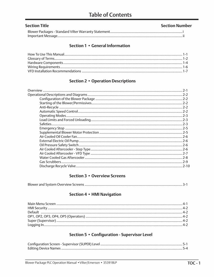
Table of Contents
Section Title Section NumberBlower Packages - Standard Vilter Warranty Statement .......................................................................... iImportant Message................................................................................................................................ ii
Section 1 • General Information
How To Use This Manual ......................................................................................................................... 1-1Glossary of Terms ................................................................................................................................... 1-2Hardware Components .......................................................................................................................... 1-4Wiring Requirements ............................................................................................................................. 1-6VFD Installation Recommendations ....................................................................................................... 1-7
Section 2 • Operation Descriptions
Overview ............................................................................................................................................... 2-1Operational Descriptions and Diagrams ................................................................................................. 2-2 Configuration of the Blower Package ......................................................................................... 2-2 Starting of the Blower/Permissives ............................................................................................. 2-2 Anti-Recycle .............................................................................................................................. 2-2 Automatic Speed Control ........................................................................................................... 2-2 Operating Modes ....................................................................................................................... 2-3 Load Limits and Forced Unloading..............................................................................................2-3 Safeties ...................................................................................................................................... 2-3 Emergency Stop ........................................................................................................................ 2-5 Supplemental Blower Motor Protection ..................................................................................... 2-5 Air Cooled Oil Cooler Fan ............................................................................................................ 2-6 External Electric Oil Pump .......................................................................................................... 2-6 Oil Pressure Safety Switch .......................................................................................................... 2-6 Air Cooled Aftercooler - Step Type .............................................................................................. 2-6 Air Cooled Aftercooler - VFD Type .............................................................................................. 2-7 Water Cooled Gas Aftercooler .................................................................................................... 2-8 Gas Scrubbers ............................................................................................................................ 2-9 Discharge Recycle Valve ............................................................................................................. 2-10
Section 3 • Overview Screens
Blower and System Overview Screens .................................................................................................... 3-1
Section 4 • HMI Navigation
Main Menu Screen ................................................................................................................................. 4-1HMI Security .......................................................................................................................................... 4-2Default ................................................................................................................................................. 4-2OP1, OP2, OP3, OP4, OP5 (Operators) ................................................................................................... 4-2Super (Supervisor) ................................................................................................................................. 4-2Logging In .............................................................................................................................................. 4-2
Section 5 • Configuration - Supervisor Level
Configuration Screen - Supervisor (SUPER) Level .................................................................................... 5-1Editing Device Names ............................................................................................................................ 5-4
TOC - 2 Blower Package PLC Operation Manual •Vilter/Emerson • 35391BLP
Table of Contents
Section Title Section Number
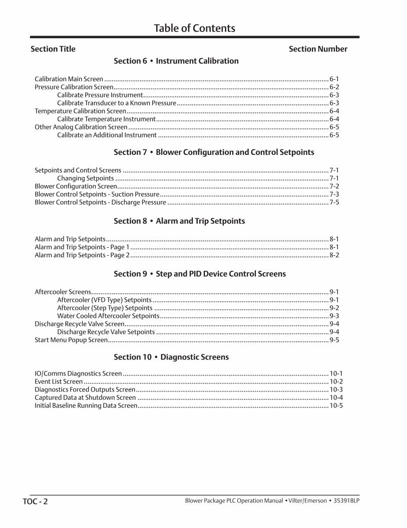
Section 6 • Instrument Calibration
Calibration Main Screen ......................................................................................................................... 6-1Pressure Calibration Screen .................................................................................................................... 6-2 Calibrate Pressure Instrument .................................................................................................... 6-3 Calibrate Transducer to a Known Pressure .................................................................................. 6-3Temperature Calibration Screen ............................................................................................................. 6-4 Calibrate Temperature Instrument .............................................................................................6-4Other Analog Calibration Screen ............................................................................................................ 6-5 Calibrate an Additional Instrument ............................................................................................ 6-5
Section 7 • Blower Configuration and Control Setpoints
Setpoints and Control Screens ............................................................................................................... 7-1 Changing Setpoints ................................................................................................................... 7-1Blower Configuration Screen .................................................................................................................. 7-2Blower Control Setpoints - Suction Pressure ........................................................................................... 7-3Blower Control Setpoints - Discharge Pressure ....................................................................................... 7-5
Section 8 • Alarm and Trip Setpoints
Alarm and Trip Setpoints ........................................................................................................................ 8-1Alarm and Trip Setpoints - Page 1 ........................................................................................................... 8-1Alarm and Trip Setpoints - Page 2 ........................................................................................................... 8-2
Section 9 • Step and PID Device Control Screens
Aftercooler Screens ................................................................................................................................ 9-1 Aftercooler (VFD Type) Setpoints ............................................................................................... 9-1 Aftercooler (Step Type) Setpoints .............................................................................................. 9-2 Water Cooled Aftercooler Setpoints ...........................................................................................9-3Discharge Recycle Valve Screen .............................................................................................................. 9-4 Discharge Recycle Valve Setpoints ............................................................................................. 9-4Start Menu Popup Screen ....................................................................................................................... 9-5
Section 10 • Diagnostic Screens
IO/Comms Diagnostics Screen ............................................................................................................... 10-1Event List Screen .................................................................................................................................... 10-2Diagnostics Forced Outputs Screen ........................................................................................................ 10-3Captured Data at Shutdown Screen ....................................................................................................... 10-4Initial Baseline Running Data Screen ....................................................................................................... 10-5

TOC - 3Blower Package PLC Operation Manual •Vilter/Emerson • 35391BLP
Section 11 • Alarms, Trips, Status Information and Troubleshooting
Alarm and Trips ...................................................................................................................................... 11-1Alarm Listing .......................................................................................................................................... 11-2Trip Listing ............................................................................................................................................. 11-9Status Messages and Blower State Indicator ........................................................................................... 11-18Troubleshooting .................................................................................................................................... 11-22 If the Blower Will Not Start ......................................................................................................... 11-22 If Control Power Will Not Turn On .............................................................................................. 11-22
Section 12 • Central Controller Communications
Communication with a Central Controller/DCS ...................................................................................... 12-1 VPN Access ................................................................................................................................ 12-1 Setting Up Communications ...................................................................................................... 12-1 Watchdog Timer ........................................................................................................................ 12-1Data that can be Read from the Blower PLC ............................................................................................ 12-1 Live Instrument Data ................................................................................................................. 12-1Alarm and Trip Data ............................................................................................................................... 12-8Status Data ............................................................................................................................................ 12-17States of Discrete I/O ............................................................................................................................. 12-21Blower State Indicator ............................................................................................................................ 12-25Data that can be Written to the Blower PLC ............................................................................................ 12-26 Discrete Blower Commands ....................................................................................................... 12-26
Section Title Section Number
Table of Contents
TOC - 4 Blower Package PLC Operation Manual •Vilter/Emerson • 35391BLP
List of Tables and Figures
Table/Figure Section Number Tables
Table 11-1. Alarm Listing ........................................................................................................................ 11-2Table 11-2. Trip Listing ........................................................................................................................... 11-9Table 11-3. Status Listing ....................................................................................................................... 11-16
Table 12-1. Engineered Units Value Interpretation (INT_OUT[x]) ........................................................... 12-2 Table 12-2. Live Instrument Data ............................................................................................................ 12-2Table 12-3. Alarm Data ........................................................................................................................... 12-8Table 12-4. Trip Data .............................................................................................................................. 12-12Table 12-5. Status Data .......................................................................................................................... 12-17Table 12-6. Discrete Input States ............................................................................................................ 12-21Table 12-7. Discrete Output States ......................................................................................................... 12-23Table 12-8. State Indicator ..................................................................................................................... 12-25Table 12-9. Blower Command (Real)....................................................................................................... 12-26Table 12-10. Blower Command (Double Integer) .................................................................................... 12-26
Figures
Figure 2-1. Operational Diagram - Load Limits / Forced Unloading (Example) ......................................... 2-4Figure 2-2. Control Panel Master Power and Emergency Stop Electrical Circuit ....................................... 2-5Figure 2-3. Operational Diagram - Air Cooled Aftercooler (Step Type) ..................................................... 2-6Figure 2-4. Operational Diagram - Air Cooled Aftercooler (VFD Type) ..................................................... 2-7Figure 2-5. Operational Diagram - Water Cooled Gas Aftercooler ........................................................... 2-8Figure 2-6. Operational Diagram - Discharge Recycle Valve .................................................................... 2-10
Figure 3-1. Basic Blower Package Screen ................................................................................................ 3-1
Figure 4-1. Main Menu Screen ................................................................................................................ 4-1Figure 4-3. Login Popup Screen .............................................................................................................. 4-2Figure 4-4. Login Screen Keyboard ......................................................................................................... 4-3
Figure 5-1. Configuration Screen - All Options Shown (Supervisor Level) ................................................ 5-1Figure 5-2. Set Date/Time Pop-Up Screen - Supervisor Level ................................................................... 5-2Figure 5-3. Change Password Pop-Up Screen - Supervisor Level .............................................................. 5-3Figure 5-4. Define Device Names - Devices and Vessels (Supervisor Level) .............................................. 5-4Figure 5-5. Define Device Names - Instrumentation (Supervisor Level) ................................................... 5-5Figure 5-6. Define Device Names - Alarm and Trip 1 (Supervisor Level) (1 of 2) ....................................... 5-6Figure 5-7. Define Device Names - Alarm and Trip 2 (Supervisor Level) (2 of 2) ....................................... 5-7
Figure 6-1. Instrument Calibration Overview Screen .............................................................................. 6-1Figure 6-2. Pressure Calibration Screen - 1 of 3 ....................................................................................... 6-2Figure 6-3. Pressure Calibration Screen - 3 of 3 ....................................................................................... 6-3Figure 6-4. Temperature Calibration Screen ........................................................................................... 6-4Figure 6-5. Other Analog Calibration Screen .......................................................................................... 6-5
Figure 7-1. Numeric Entry Pop-up Screen ............................................................................................... 7-1Figure 7-2. Blower Configuration Screen ................................................................................................ 7-2 Figure 7-3. Blower Control Screen - Suction Pressure .............................................................................. 7-4Figure 7-4. Blower Control Screen - Discharge Pressure .......................................................................... 7-5
TOC - 5Blower Package PLC Operation Manual •Vilter/Emerson • 35391BLP
Figure 8-1. Alarm and Trip Setpoints Screen - 1 of 2 ................................................................................ 8-1Figure 8-2. Alarm and Trip Setpoints Screen - 2 of 2 ................................................................................ 8-2
Figure 9-1. Aftercooler (VFD Type) Screen .............................................................................................. 9-1Figure 9-2. Aftercooler (Step Type) Screen ............................................................................................. 9-2Figure 9-3. Water Cooled Aftercooler Screen .......................................................................................... 9-3Figure 9-4. Discharge Recycle Valve Screen ............................................................................................ 9-4Figure 9-5. Start Menu ........................................................................................................................... 9-5
Figure 10-1. IO/Comms Diagnostics Screen ........................................................................................... 10-1 Figure 10-2. Event List Screen ................................................................................................................. 10-2Figure 10-3. Diagnostics Forced Output Screen ...................................................................................... 10-3Figure 10-4. Captured Data at Shutdown Screen .................................................................................... 10-4Figure 10-5. Initial Baseline Running Data Screen ................................................................................... 10-5
Figure 11-1. Alarm/Trip/Status Bars (Main Menu Screen) ........................................................................ 11-1Figure 11-2. Alarm Popup Screen ........................................................................................................... 11-1Figure 11-3. Alarm/Trip/Status Bars (Main Menu Screen) ........................................................................ 11-18
List of Tables and Figures
Table/Figure Section Number

Blank / TOC Blower Package PLC Operation Manual •Vilter/Emerson • 35391BLP
1 – 1Blower Package PLC Operation Manual •Vilter/Emerson • 35391BLP
Section 1 • General Information
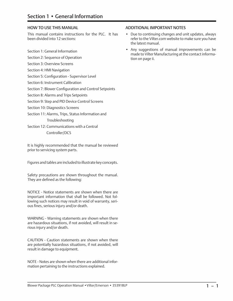
HOW TO USE THIS MANUAL
This manual contains instructions for the PLC. It has been divided into 12 sections:
Section 1: General Information
Section 2: Sequence of Operation
Section 3: Overview Screens
Section 4: HMI Navigation
Section 5: Confi guration - Supervisor Level
Section 6: Instrument Calibration
Section 7: Blower Confi guration and Control Setpoints
Section 8: Alarms and Trips Setpoints
Section 9: Step and PID Device Control Screens
Section 10: Diagnostics Screens
Section 11: Alarms, Trips, Status Information and
Troubleshooting
Section 12: Communications with a Central
Controller/DCS
It is highly recommended that the manual be reviewed prior to servicing system parts.
Figures and tables are included to illustrate key concepts.
Safety precautions are shown throughout the manual. They are defi ned as the following:
NOTICE - Notice statements are shown when there are important information that shall be followed. Not fol-lowing such notices may result in void of warranty, seri-ous fi nes, serious injury and/or death.
WARNING - Warning statements are shown when there are hazardous situations, if not avoided, will result in se-rious injury and/or death.
CAUTION - Caution statements are shown when there are potentially hazardous situations, if not avoided, will result in damage to equipment.
NOTE - Notes are shown when there are additional infor-mation pertaining to the instructions explained.
ADDITIONAL IMPORTANT NOTES
• Due to continuing changes and unit updates, always refer to the Vilter.com website to make sure you have the latest manual.
• Any suggestions of manual improvements can be made to Vilter Manufacturing at the contact informa-tion on page ii.

1 – 2 Blower Package PLC Operation Manual •Vilter/Emerson • 35391BLP
Section 1 • General Information
Discharge Recycle Control PressurePressure of discharge gas measured at the Discharge Recycle Valve. Used to control the Discharge Recycle Valve.
Discharge Recycle Valve
Motorized or Air Actuated Valve that recycles discharge gas back to the suction side of the blower package.
Discharge Pressure
Pressure of the refrigerant or gas measured at the outlet of the blower.
Discharge Temperature
Temperature of the refrigerant or gas measured at the outlet of the blower.
Ethernet IP
Communication protocol used to communicate to the blower PLC.
General TripShutdown condition that applies to the entire blower package. If active, will shut down the entire package.
HMI
HMI stands for “Human-Machine Interface.” The blower HMI is a touchscreen terminal mounted in the door of the blower control enclosure.
Inlet Scrubber
Vessel located on the inlet side of gas blower or gas chill-er to remove moisture and/or contaminants.
Inlet Scrubber Inlet Pressure
Pressure of gas measured at the inlet of the inlet scrubber.
Inlet Scrubber Outlet Pressure
Pressure of gas measured at the outlet of the inlet scrubber.
Inlet Scrubber Pressure Drop
Pressure differential between inlet and outlet of the in-let scrubber. Calculated: Scrubber Inlet Pressure minus Scrubber Outlet Pressure.
Main Motor
AC induction motor that is coupled to and drives the blower.
Aftercooler Heat Exchanger
Used to cool discharge gas from the blower package.
Aftercooler Outlet Temperature
Temperature of gas measured at the outlet of the Aftercooler.
Alarm Warning
Annunciated by the blower PLC that an operational or process condition is abnormal. When active, alarms will be displayed but will not shut down the blower package.
Bearing Temperature
Temperature of the bearings of the blower main motor measured by an RTD.
Blower
Positive displacement rotary compressor intended to move high volume of gas at relatively low pressure.
Blower Offset Dwell Time
Amount of time between starting individual blowers. Used in applications where all blowers on a package starting at the same time would put too great of a bur-den on the electrical infrastructure.
Blower Package
Arrangement of up to 4 blowers controlled by a com-mon PLC controller.
Blower-Specifi c Trip
A shutdown condition that applies to a specifi c blower.
Differential Pressure
The difference between two pressures.
Discharge Recycle Control Pressure
Pressure of discharge gas measured at the Discharge Recycle Valve. Used to control the Discharge Recycle Valve.
Glossary of Terms
1 – 3Blower Package PLC Operation Manual •Vilter/Emerson • 35391BLP
Section 1 • General Information
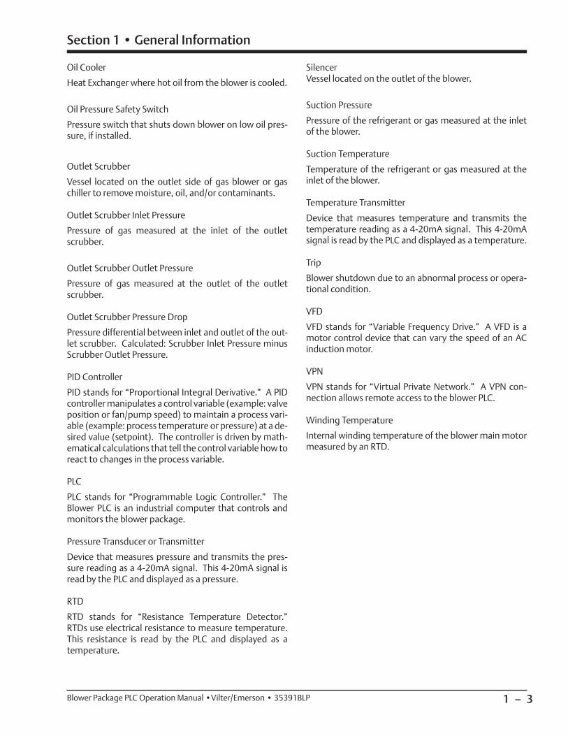
Oil Cooler
Heat Exchanger where hot oil from the blower is cooled.
Oil Pressure Safety Switch
Pressure switch that shuts down blower on low oil pres-sure, if installed.
Outlet Scrubber
Vessel located on the outlet side of gas blower or gas chiller to remove moisture, oil, and/or contaminants.
Outlet Scrubber Inlet Pressure
Pressure of gas measured at the inlet of the outlet scrubber.
Outlet Scrubber Outlet Pressure
Pressure of gas measured at the outlet of the outlet scrubber.
Outlet Scrubber Pressure Drop
Pressure differential between inlet and outlet of the out-let scrubber. Calculated: Scrubber Inlet Pressure minus Scrubber Outlet Pressure.
PID Controller
PID stands for “Proportional Integral Derivative.” A PID controller manipulates a control variable (example: valve position or fan/pump speed) to maintain a process vari-able (example: process temperature or pressure) at a de-sired value (setpoint). The controller is driven by math-ematical calculations that tell the control variable how to react to changes in the process variable.
PLC
PLC stands for “Programmable Logic Controller.” The Blower PLC is an industrial computer that controls and monitors the blower package.
Pressure Transducer or Transmitter
Device that measures pressure and transmits the pres-sure reading as a 4-20mA signal. This 4-20mA signal is read by the PLC and displayed as a pressure.
RTD
RTD stands for “Resistance Temperature Detector.” RTDs use electrical resistance to measure temperature. This resistance is read by the PLC and displayed as a temperature.
SilencerVessel located on the outlet of the blower.
Suction Pressure
Pressure of the refrigerant or gas measured at the inlet of the blower.
Suction Temperature
Temperature of the refrigerant or gas measured at the inlet of the blower.
Temperature Transmitter
Device that measures temperature and transmits the temperature reading as a 4-20mA signal. This 4-20mA signal is read by the PLC and displayed as a temperature.
Trip
Blower shutdown due to an abnormal process or opera-tional condition.
VFD
VFD stands for “Variable Frequency Drive.” A VFD is a motor control device that can vary the speed of an AC induction motor.
VPN
VPN stands for “Virtual Private Network.” A VPN con-nection allows remote access to the blower PLC.
Winding Temperature
Internal winding temperature of the blower main motor measured by an RTD.
1 – 4 Blower Package PLC Operation Manual •Vilter/Emerson • 35391BLP
Section 1 • General Information
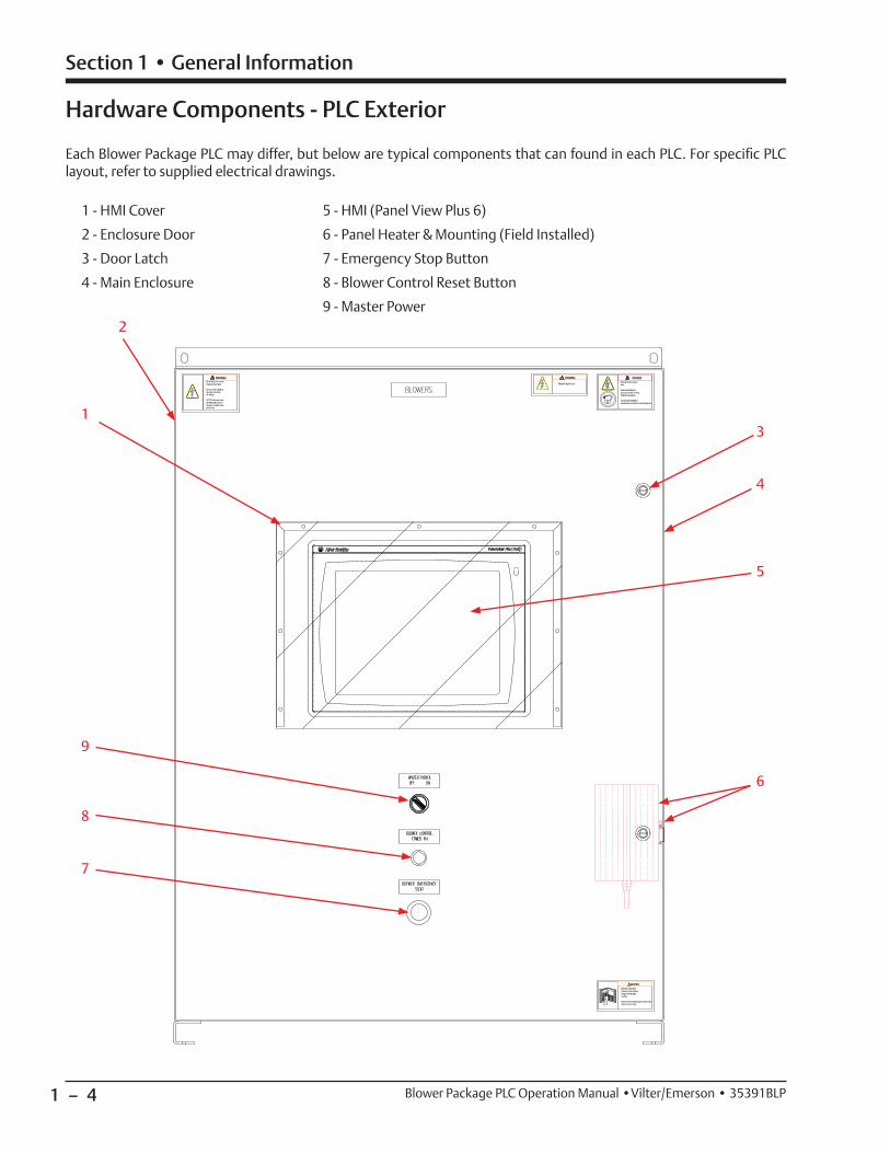
Hardware Components - PLC Exterior
Each Blower Package PLC may differ, but below are typical components that can found in each PLC. For specifi c PLC layout, refer to supplied electrical drawings.
1 - HMI Cover
2 - Enclosure Door
3 - Door Latch
4 - Main Enclosure
5 - HMI (Panel View Plus 6)
6 - Panel Heater & Mounting (Field Installed)
7 - Emergency Stop Button
8 - Blower Control Reset Button
9 - Master Power
1
2
4
3
7
8
9
5
6
1 – 5Blower Package PLC Operation Manual •Vilter/Emerson • 35391BLP
Section 1 • General Information
N1
11111112111311141115
20512071209121112131215121712191221122312251227122912311233125312551
2831
N1N1N1N1N1N1N1N1N1
10811081
108110811081
2591
1081
2571
100111001210031
1007210091
10131
10151101521017110172101911019210211102121023110251
1011110112
10252
1029110292103111031210331
26112631265126712691271127312751277127912811
3231
30313051307130913111313131513171
31913211
32713251
329133113331
41814321434146814701472147414761
10332
10352103711039110392
10351
10511
105311053210571105721059110611
10512
10612
106511065210671106721069110692
10712107311075110752
10711
11011
11031110321105111052
11012
111311113211151111521117111172
1124211262
47814801
N1
GN
D
1281
1282
N1N1
GND1011
5071
5101
5131
5161
5661
5601SH SHSH SH 5191
5631
6051
5751
5781SH 6111
6061
6141SH 5691
5721SH 6211
6201SH 5221
5251SH 5281
5571 SH 6121
SH 6151
1584
6551
6561
SH 6581
6591
SH6641
6651
6701
6711
SH 6731
6741
6761
6771
SHSH SH SH SH SH SH 6081
6091
SH SH SH SH 6241
6231 SH 6271
6261 SH 6301
6291 SH SH 6611
6621
SH SH 6791
6801
SH SH SH
48214841
1584
1584
1584
1584
1584
1584
1584
1584
1584
1584
1584
1584
1584
1584
1584
1134
2
GN
D
100321005110071
1081
10811081
1081
1081
1081
1081
1161211632
GN
D
1583
GN
D
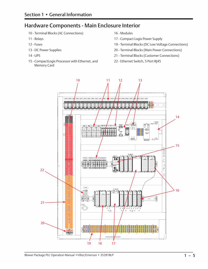
10 - Terminal Blocks (AC Connections)
11 - Relays
12 - Fuses
13 - DC Power Supplies
14 - UPS
15 - CompactLogix Processor with Ethernet, and Memory Card
16 - Modules
17 - Compact Logix Power Supply
19 - Terminal Blocks (DC Low Voltage Connections)
20 - Terminal Blocks (Main Power Connections)
21 - Terminal Blocks (Customer Connections)
22 - Ethernet Switch, 5 Port RJ45
Hardware Components - Main Enclosure Interior
10 11 12 13
22
21
20
19 17
16
16
14
15
1 – 6 Blower Package PLC Operation Manual •Vilter/Emerson • 35391BLP
Section 1 • General Information
• Incoming power enters on the left bottom wall of the PLC control enclosure. Route these conductors in the space between the sub-panel and inside wall of the enclosure.
• DC control, analog and communications or network wiring enters on the right bottom wall of the PLC con-trol enclosure.
• Wiring external to the panel per NEC (NFPA 70), ANSI 12.12.01 and UL-598A.
• Panel construction and wiring per UL-508A for all panels and ANSI 12.12.01 and UL-698A for hazardous locations.
• Electrical transmission, control, and alarm wiring shall be stranded copper no smaller than #14 AWG. Use JIC color code, unless otherwise noted.
• All control circuits from a source outside of this panel are to be #14 AWG Orange.
• All control circuit neutrals from a source outside of this panel are to be no smaller than #14 AWG White/Orange Tracer.
• All analog inputs are to be connected with shielded cable. Shield terminated at panel side and isolated at device side.
• All shielding is to be grounded at a single point on the chassis.
• Analog wiring must be run separate from AC wiring and kept separate within the enclosure.
• All analog signal wiring shall be grounded at one end only. Ground shield of signal cables.
• Use alpha P/N 2423C, 3 Cond, 18 AWG, shielded or approved equal.
• Only one customer network cable to switch.
• Unused defi ned as having a previous assignment. Spare defi ned as no previous assignment.
• Where applicable, remove jumper between connec-tions if used.
• All power circuits from a source outside of this panel are to be no smaller than #12 AWG Orange.
• All power circuit neutrals from a source outside of this panel are to be no smaller than #12 AWG White/Orange Tracer.
• All equipment grounds must be Green/Yellow. For ground conductors larger than #6 AWG, apply Green/Yellow heat shrink or color conductor with marker at both ends.
• All power sources for heating devices shall be sup-plied by others.
• Designated for a trip function (i.e. limit trip, se-quence shutdown, etc.). Recommended hard wire connection.
• Use alpha P/N 2422C, 2 Cond, 18 AWG, shielded or approved equal.
• Category 6 Ethernet cable is recommended for all of our equipment.
SEPARATION OF INTRINSICALLY SAFE CIRCUITS (IF USED)
The intrinsically safe wiring enters on the bottom-left wall of the PLC control enclosure.
To reduce the possibility of interconnection, additional requirements exist for the separation of intrinsically safe and non-intrinsically safe circuits. Exceptions to this rule may be found in NEC Section 504-30(A)(1) and (2).
Separation by distance:
• The distance between intrinsically safe fi eld wiring terminals and non-intrinsically safe fi eld wiring termi-nals shall be a minimum 8 inches.
• The distance between intrinsically safe fi eld wiring terminals and non-intrinsically safe fi eld circuits shall be a minimum 5 inches.
• The distance between intrinsically safe fi eld wiring terminals and non-intrinsically safe fi eld circuits and wiring shall be a minimum 5 inches.
• The distance between intrinsically safe fi eld wiring terminals and non-intrinsically safe internal wiring shall be a minimum 2 inches.
Wiring Requirements
1 – 7Blower Package PLC Operation Manual •Vilter/Emerson • 35391BLP
Section 1 • General Information
• All wiring to and from the Variable Frequency Drive (VFD) starter shall conform to the National Fire Protetcion Association 70 (NFPA-70), local codes and the manufacturer’s guidelines and specifi cations.
• Thoroughly read the manufacturer’s VFD installation and instruction manuals.
• In the event of a code and manufacturer recom-mendation confl ict, always use the more stringent standard.
• Only use an inverter duty rated motor built to NEMA MG1 PART 30 & 31.
• Always used copper conductors to feed the VFD starter and motor. Use cable with thermoset insula-tion such as XLPE or XHHW-2 from the VFD to motor.
• It is preferred to use VFD cable, service wire company or equal, between the VFD and the motor per manu-facturer’s instructions.
• It is preferred to use continuous metal conduit to the VFD starter to the motor.
• If non-metallic conduit is used, VFD cable must be used.
• If using VFD cable in metal conduit, the metal con-duit must be insulated at the motor, so that the metal conduit is not a continuous run.
• Always use fl exible metallic liquid-tight conduit to feed the motor from metallic conduit.
• Grounding conductor must run from the VFD ground terminals directly to the motor conduit box. Always use proper grounding techniques (Star Method) and sized according to the NFPA 70 NEC.
• Always use bonding bushings on all conduit ends,
• Always use bonding bushings on all conduit ends, with proper size braided copper cable bonded to the starter panel.
• All grounding and bonding conductors and lugs must terminate on bare metal and not to painted surfaces.
• Always use a minimum of 3% impedance line reactor such as MTE or equal.
• Where the cables to the motor are longer than 50’, always use a load reactor (customer must provide Vilter with cable lengths from feeder to starter and from starter to motor).
• Where the cables to the motor are longer than 500’, always use a DV/DT load fi lter (customer must pro-vide Vilter with cable lengths from feeder to starter and from starter to motor).
• Where the cables to the motor are longer than 1000’, always use a sine fi lter (customer must provide Vilter with cable lengths from feeder to starter and from starter to motor).
• Line and load conductors must be separated, as much as the starter cabinet will allow, and cannot be in the same conduit or cable chase.
• By no means shall power and control cables run in parallel - cables must be separated, as much as the starter cabinet will allow, and cannot be in the same conduit or cable chase.
• For analog signals, use twisted shielded control cable rated for 600V.
• When a generator is feeding a VFD starter, use a 5% line reactor.
• Some countries require RFI/EMI fi lters -- please con-sult country codes and standards.
• As an insurance policy against motor shaft currents, use a split ring bearing protection ring on the motor shaft with the non-load bearing insulated.
VFD Installation Recommendations

1 – 8 / Blank Blower Package PLC Operation Manual •Vilter/Emerson • 35391BLP
2 – 1
Section 2 • Operational Descriptions
Blower Package PLC Operation Manual •Vilter/Emerson • 35391BLP
Overview
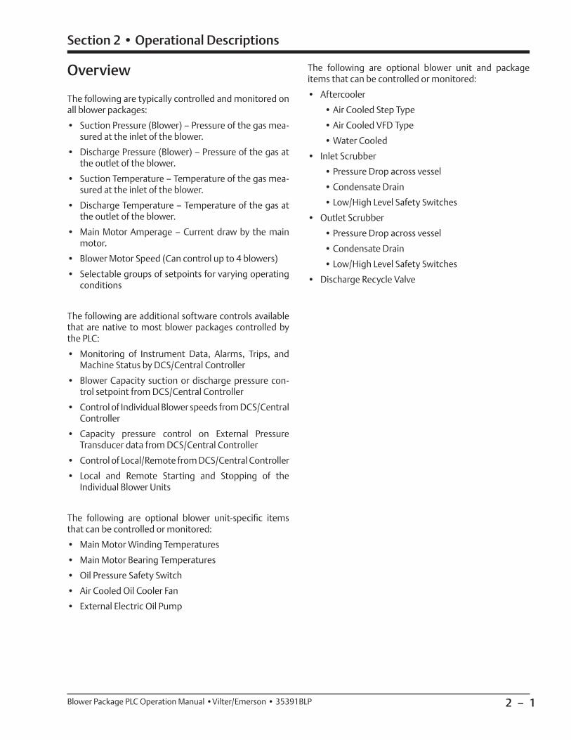
The following are typically controlled and monitored on all blower packages:
• Suction Pressure (Blower) – Pressure of the gas mea-sured at the inlet of the blower.
• Discharge Pressure (Blower) – Pressure of the gas at the outlet of the blower.
• Suction Temperature – Temperature of the gas mea-sured at the inlet of the blower.
• Discharge Temperature – Temperature of the gas at the outlet of the blower.
• Main Motor Amperage – Current draw by the main motor.
• Blower Motor Speed (Can control up to 4 blowers)
• Selectable groups of setpoints for varying operating conditions
The following are additional software controls available that are native to most blower packages controlled by the PLC:
• Monitoring of Instrument Data, Alarms, Trips, and Machine Status by DCS/Central Controller
• Blower Capacity suction or discharge pressure con-trol setpoint from DCS/Central Controller
• Control of Individual Blower speeds from DCS/Central Controller
• Capacity pressure control on External Pressure Transducer data from DCS/Central Controller
• Control of Local/Remote from DCS/Central Controller
• Local and Remote Starting and Stopping of the Individual Blower Units
The following are optional blower unit-specifi c items that can be controlled or monitored:
• Main Motor Winding Temperatures
• Main Motor Bearing Temperatures
• Oil Pressure Safety Switch
• Air Cooled Oil Cooler Fan
• External Electric Oil Pump
The following are optional blower unit and package items that can be controlled or monitored:
• Aftercooler
• Air Cooled Step Type
• Air Cooled VFD Type
• Water Cooled
• Inlet Scrubber
• Pressure Drop across vessel
• Condensate Drain
• Low/High Level Safety Switches
• Outlet Scrubber
• Pressure Drop across vessel
• Condensate Drain
• Low/High Level Safety Switches
• Discharge Recycle Valve
2 – 2
Section 2 • Operational Descriptions
Blower Package PLC Operation Manual •Vilter/Emerson • 35391BLP
Operational Descriptions and Diagrams
CONFIGURATION OF THE BLOWER PACKAGE
The Blower package PLC can control up to 4 blowers. The blowers can be independently confi gured to run on a fi xed speed setpoint, PID Control (variable speed), or taken out of service:
• Fixed Speed: In auto mode, individual blowers can be confi gured to run on 1 of 4 fi xed speeds.
• Variable Speed: The individual blower’s speed will be controlled by a PID controller to hold a suction or discharge pressure setpoint. If multiple blowers are confi gured to run on PID control, all will run off of a common speed command from the PID controller.
• Out of Service: Individual blowers may be taken out of service for demand considerations or mainte-nance. When a blower is out of service, alarms, trips, and status messages specifi c to that blower will not be generated.
Additionally, individual blowers may be enabled and dis-abled “on the fl y,” either locally or remotely (by commu-nications) without having to take them out of service.
Functions such as anti-recycle, and selected alarms and trips are blower specifi c, meaning if active, they apply only to the affected blower. This way if one blower trips or is in anti-recycle, the other blowers are allowed to run.
At start, the blowers may be confi gured to start offset from each other, to lessen the burden on the electrical infrastructure due to motor inrush.
STARTING OF THE BLOWER/PERMISSIVES
To run the blower package, it must me started from the “Start Menu” screen on the control panel HMI. Pressing “Unit Start” in the “Start Menu” screen will initiate a start if all permissives to initiate a start are met. To initiate a start, the following conditions must be met:
• Control Power is ON (Emergency Stop button is not pressed and Master Control Relay is energized, indi-cated by pilot light on front of panel)
• Blower Confi guration is valid
• No Active General Trips (trips that apply to the whole blower package)
NOTE
If an individual blower trips, in order to restart blower, it must fi rst clear trip condition and be re-enabled locally
at the control panel.
When a start is initiated, the blower package will start if all permissives to run are met. If all permissives to run
are not met, the control will wait in a “standby” mode until all conditions to run are satisfi ed. Any condition that the control is waiting on is annunciated on the over-view and menu screens and logged in the Event List. For the blowers to start running, the following must be met:
• Control Power is ON (Emergency Stop button is not pressed and Master Control Relay is energized, indi-cated by pilot light on front of panel)
• No Active General Trips
• Blower Package start has been initiated by pressing “Unit Start” in the “Start Menu” screen.
• Remote Permissive input is ON
• Soft run permissive from the DCS/Central Controller is ON (if control by communications selected)
• Blower Anti-Recycle Timer is not active (specifi c to each blower – each blower has its own anti-recycle function.)
• No Blower-Specifi c Trips Active (specifi c to each blower)
ANTI-RECYCLE
After a blower motor stops, it is not allowed to re-start again for a settable time. This is to protect the blower motor. If the Anti-Recycle timer is active, a banner will appear next to the specifi c blower on the main screen that shows the remaining time. If a start is initiated, the blower state indicator will indicate “Standby” until the Anti-Recycle timer is done. If all other permissives are met, the blower will re-start when its anti-recycle timer expires. In multiple-blower applications, the anti-recycle function is blower specifi c – one or more blowers may be in anti-recycle without affecting the operation of other blowers on the package.
AUTOMATIC SPEED CONTROL
For blowers that are confi gured to run on PID speed con-trol, a PID controller will adjust the speed of the blowers to hold a pressure set point. Two control methods are available:
• Discharge Pressure Control: Blower increases speed to increase discharge Pressure to desired setpoint
• Suction Pressure Control: Blower increases speed to lower suction pressure to desired setpoint
Any blowers confi gured to run on PID speed control re-ceive the same speed command from the PID control-ler. Blowers confi gured to run on fi xed speed control will maintain their fi xed speed set point. Variables that fac-tor in to the automatic speed control are the following:
• Target pressure – the desired suction or discharge pressure the blower package will try to maintain.
2 – 3
Section 2 • Operational Descriptions
Blower Package PLC Operation Manual •Vilter/Emerson • 35391BLP
• Deadband – Range above and below target pressure where no speed adjustment will be made.
• Proportional Gain (Kp) – Proportional Term of the PID equation
• Integral Gain (Ki) – Integral term of the PID equation
• Derivative Gain (Kd) – Derivative Gain of the PID equation.
OPERATING MODES
The speed control of the blower package can be confi g-ured to operate in several ways, depending on the needs of the site. This mode selection is made at the “Start Menu” screen. There are four basic modes, described below:
• Local-Auto: The blower controller will adjust the speed of the blowers to maintain the target pressure set point. The target pressure setpoint is set on the local HMI. Blowers will run off of the PID controller’s speed command or fi xed speed set point, according to how the individual blowers are confi gured.
• Local-Manual: The operator is in control of the indi-vidual blower speeds from the local HMI. When in Local-Manual mode, the operator controls the speed of each blower by adjusting the manual speed set points on the blower overview screen.
• Remote-Auto: The blower controller will adjust the speed of the blowers to maintain the target pressure set point. Blowers will run off of the PID controller’s speed command or fi xed speed set point, according to how the individual blowers are confi gured. The tar-get pressure setpoint is defi ned by the DCS/Central Controller via communications. (NOTE: Control by Communications must be enabled to use this mode.)
• Remote-Manual: Individual blower speed commands are controlled by a DCS or Central Controller via com-munications. (NOTE: Control by Communications must be enabled to use this method.)
In any of the above modes, all local alarms and trips will still apply.
For safety reasons, remote mode is only enabled if Control by Communications is enabled.
In the event that the communications link between the blower PLC and the central controller/DCS is lost, the ac-tion taken is selectable from the Confi guration screen. The machine will Trip or revert to Local mode and con-tinue to run depending on the selection.
The blower PLC can be remotely commanded to Local or Remote Mode if Control by Communications is enabled.
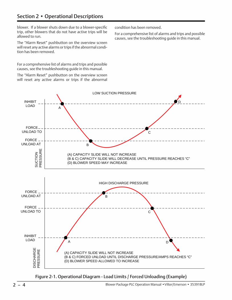
LOAD LIMITS AND FORCED UNLOADING
Reference example, Figure 2-1
To protect the blower package and process, the control-ler will inhibit the blower from increasing speed or force it to decrease speed if certain variables get outside of set ranges. Load limits and forced unloading will also affect blowers that are confi gured to PID speed control. The load limiting variable depends on what control mode the blower package is in.
• In Discharge Pressure Control, the load limiting will be controlled by suction pressure.
• In Suction Pressure Control, the load limiting will be controlled by discharge pressure.
Three set points are used to control load limits and forced unloading:
• Inhibit Loading: when this setpoint is reached, the blower will not be allowed to increase speed
• Unload at: when this setpoint is reached, the blower motor will decrease speed by a settable rate (forced unload) until the “Unload To” setpoint is reached.
• Unload To: this is the setpoint at which the blower motor will stop decreasing speed from a forced un-load condition.
When a load limit or forced unload condition is active it will be annunciated in the status banner on the overview and menu HMI screens, and will also be logged in the event list.
SAFETIES
The blower controller continuously monitors opera-tional and process data and annunciates an alarm and/or stops the machine if any condition becomes abnormal. Two levels of safeties exist when an abnormal condition is detected.
• Alarm: If active, alarms are annunciated on the blow-er HMI. When activated, a popup screen showing the date and time of the alarm and alarm message will appear. Alarms are also logged in the Event List. An alarm serves only as a warning to the operator; if an alarm is active the machine is still allowed to run.
• Trip: If active, trips will shut the machine down or not allow the blower to start. Trips are annunciated on the blower HMI. When activated, a popup screen showing the date and time of the trip and trip mes-sage will appear. Trips are also logged in the Event List.
Alarms and Trips may be general or blower-specifi c. A general trip will shut down the entire blower package, a blower-specifi c trip will only shut down the affected
2 – 4
Section 2 • Operational Descriptions
Blower Package PLC Operation Manual •Vilter/Emerson • 35391BLP
blower. If a blower shuts down due to a blower-specifi c trip, other blowers that do not have active trips will be allowed to run.
The “Alarm Reset” pushbutton on the overview screen will reset any active alarms or trips if the abnormal condi-tion has been removed.
For a comprehensive list of alarms and trips and possible causes, see the troubleshooting guide in this manual.
The “Alarm Reset” pushbutton on the overview screen will reset any active alarms or trips if the abnormal
condition has been removed.
For a comprehensive list of alarms and trips and possible causes, see the troubleshooting guide in this manual.
INHIBIT LOAD
FORCEUNLOAD TO
FORCE UNLOAD AT
DIS
CH
AR
GE
P
RE
SS
UR
E
LOW SUCTION PRESSURE
A
B
C
D
INHIBIT LOAD
FORCE UNLOAD TO
FORCE UNLOAD AT
HIGH DISCHARGE PRESSURE
A
B
C
D
(A) CAPACITY SLIDE WILL NOT INCREASE(B & C) CAPACITY SLIDE WILL DECREASE UNTIL PRESSURE REACHES “C”(D) BLOWER SPEED MAY INCREASE
(A) CAPACITY SLIDE WILL NOT INCREASE(B & C) FORCED UNLOAD UNTIL DISCHARGE PRESSURE/AMPS REACHES “C”(D) BLOWER SPEED ALLOWED TO INCREASE
SU
CTI
ON
P
RE
SS
UR
E
Figure 2-1. Operational Diagram - Load Limits / Forced Unloading (Example)

2 – 5
Section 2 • Operational Descriptions
Blower Package PLC Operation Manual •Vilter/Emerson • 35391BLP
EMERGENCY STOP
Reference Figure 2-2
The Emergency Stop circuit in the blower control pan-el energizes the Master Control Relay, which provides power to PLC outputs that control actuators, heaters, motor starters, valves, etc. The Master Control Relay may be energized by pressing the “Control Power On” illuminated pushbutton on the door of the blower con-trol panel. When the Master Control Relay is energized, the “Control Power On” pushbutton will illuminate. The following conditions must be satisfi ed to energize the Master Control Relay:
• Emergency Stop pushbutton on the door of the blow-er control panel must be pulled out.
• Any additional Emergency stops or safety devices tied in to the Emergency Stop circuit must be reset.
• The blower PLC must be booted up and operational.
• The 24-volt DC power supplies in the blower control panel must be powered up and OK.
SUPPLEMENTAL BLOWER MOTOR PROTECTION
In the event that the controller detects a blower motor running when it is not being commanded to run by the controller, the controller will energize a blower-specifi c supplemental shutdown output. This output can be used to control a shunt trip, under-voltage release, iso-lation contactor, or other safety power removal device.
Figure 2-2. Control Panel Master Power and Emergency Stop Electrical Circuit
2 – 6
Section 2 • Operational Descriptions
Blower Package PLC Operation Manual •Vilter/Emerson • 35391BLP
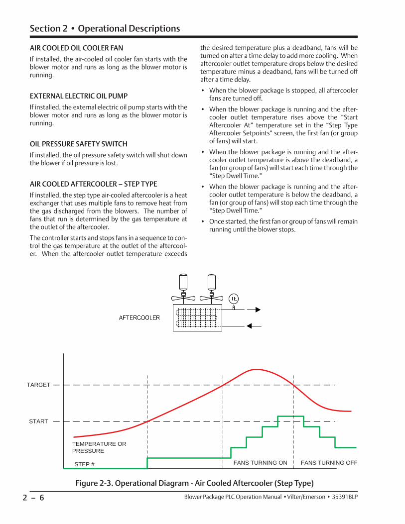
AIR COOLED OIL COOLER FAN
If installed, the air-cooled oil cooler fan starts with the blower motor and runs as long as the blower motor is running.
EXTERNAL ELECTRIC OIL PUMP
If installed, the external electric oil pump starts with the blower motor and runs as long as the blower motor is running.
OIL PRESSURE SAFETY SWITCH
If installed, the oil pressure safety switch will shut down the blower if oil pressure is lost.
AIR COOLED AFTERCOOLER – STEP TYPE
If installed, the step type air-cooled aftercooler is a heat exchanger that uses multiple fans to remove heat from the gas discharged from the blowers. The number of fans that run is determined by the gas temperature at the outlet of the aftercooler.
The controller starts and stops fans in a sequence to con-trol the gas temperature at the outlet of the aftercool-er. When the aftercooler outlet temperature exceeds
the desired temperature plus a deadband, fans will be turned on after a time delay to add more cooling. When aftercooler outlet temperature drops below the desired temperature minus a deadband, fans will be turned off after a time delay.
• When the blower package is stopped, all aftercooler fans are turned off.
• When the blower package is running and the after-cooler outlet temperature rises above the “Start Aftercooler At” temperature set in the “Step Type Aftercooler Setpoints” screen, the fi rst fan (or group of fans) will start.
• When the blower package is running and the after-cooler outlet temperature is above the deadband, a fan (or group of fans) will start each time through the “Step Dwell Time.”
• When the blower package is running and the after-cooler outlet temperature is below the deadband, a fan (or group of fans) will stop each time through the “Step Dwell Time.”
• Once started, the fi rst fan or group of fans will remain running until the blower stops.
START
STEP #
TARGET
TEMPERATURE OR PRESSURE
FANS TURNING ON FANS TURNING OFF
Figure 2-3. Operational Diagram - Air Cooled Aftercooler (Step Type)

2 – 7
Section 2 • Operational Descriptions
Blower Package PLC Operation Manual •Vilter/Emerson • 35391BLP
AIR COOLED AFTERCOOLER – VFD TYPE
If installed, the VFD type air cooled aftercooler is a heat exchanger that uses one or more fans running on a VFD to remove heat from the gas discharged from the blow-ers. The VFD speeds up or slows down the fan motor to control the amount of cooling done by the aftercooler.
A PID controller adjusts the speed of the fan(s) to main-tain the outlet gas temperature of the aftercooler. When the aftercooler outlet temperature exceeds the desired temperature plus a deadband, the fan(s) will increase speed to add more cooling. When aftercooler outlet temperature drops below the desired temperature mi-nus a deadband, the fan(s) will decrease speed.
• When the blower package is stopped, the aftercooler fan(s) will stop.
• When the blower package is running and the gas af-tercooler outlet temperature rises above the “Start Aftercooler At” set in the “VFD Type Aftercooler Setpoints” screen, the fan(s) will start at a settable
Figure 2-4. Operational Diagram - Air Cooled Aftercooler (VFD Type)
minimum speed.
• When the blower package is running and the after-cooler outlet temperature is above the deadband, the PID controller will increase fan speed.
• When the blower package is running and the after-cooler outlet temperature is below the deadband, the PID controller will decrease fan speed.
2 – 8
Section 2 • Operational Descriptions
Blower Package PLC Operation Manual •Vilter/Emerson • 35391BLP
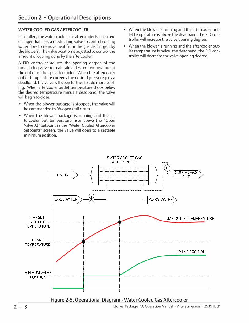
WATER COOLED GAS AFTERCOOLER
If installed, the water-cooled gas aftercooler is a heat ex-changer that uses a modulating valve to control cooling water fl ow to remove heat from the gas discharged by the blowers. The valve position is adjusted to control the amount of cooling done by the aftercooler.
A PID controller adjusts the opening degree of the modulating valve to maintain a desired temperature at the outlet of the gas aftercooler. When the aftercooler outlet temperature exceeds the desired pressure plus a deadband, the valve will open further to add more cool-ing. When aftercooler outlet temperature drops below the desired temperature minus a deadband, the valve will begin to close.
• When the blower package is stopped, the valve will be commanded to 0% open (full close).
• When the blower package is running and the af-tercooler out temperature rises above the “Open Valve At” setpoint in the “Water Cooled Aftercooler Setpoints” screen, the valve will open to a settable minimum position.
• When the blower is running and the aftercooler out-let temperature is above the deadband, the PID con-troller will increase the valve opening degree.
• When the blower is running and the aftercooler out-let temperature is below the deadband, the PID con-troller will decrease the valve opening degree.
Figure 2-5. Operational Diagram - Water Cooled Gas Aftercooler
2 – 9
Section 2 • Operational Descriptions
Blower Package PLC Operation Manual •Vilter/Emerson • 35391BLP
GAS SCRUBBERS
A gas scrubber (or knockout drum) is a vessel with a vane pack and/or coalescing elements installed to remove moisture and other contaminants from the gas stream. Gas scrubbers may be installed on the suction side or discharge side of a blower package (if an aftercooler is used, the scrubber is installed downstream of the after-cooler). A condensate pump or solenoid valve drains ac-cumulated moisture from the vessel.
Gas scrubbers include the following devices:
• Pressure transducers on the inlet and outlet of the vessel – used to measure pressure drop across the demister pad or coalescing elements to help deter-mine when to clean or replace.
• Level switches to monitor the condensate level:
• LSH (High Level) – when liquid level reaches the LSH level switch, an alarm is annunciated on the blower HMI.
• LSHH (High High Level) – when liquid level reaches the LSHH level switch, an alarm or trip is annunci-ated on the blower HMI. The alarm or trip action is confi gurable depending on the site and location
of the vessel. If trip action is selected, the blower will shut down if the LSHH is activated. Typically the purpose of the LSHH is to alarm or shut down the blower package to prevent bringing liquid into the blower suction.
• LSLL (Low Low Level) – when liquid level drops below the LSLL level switch, an alarm or trip is an-nunciated on the blower HMI. The alarm or trip action is confi gurable depending on the site and location of the vessel. If trip action is selected, the blower will shut down if the LSLL is activated. Typically the purpose of the LSLL is to detect if the liquid seal is lost to prevent introducing gas into the condensate drain system.
• Condensate Drain System:
• A drain pump or solenoid valve will turn on when the liquid level in the scrubber reaches the “Cutin” level switch.
• The drain pump or solenoid valve will turn off when the liquid level in the scrubber drops to the “Cutout” level switch.
• Dual pumps may be used. Selection of Pump A or B is made in the Confi guration screen.
2 – 10
Section 2 • Operational Descriptions
Blower Package PLC Operation Manual •Vilter/Emerson • 35391BLP
BLOWERCONTROLTARGET
0
100
DISCHARGE RECYCLE SETTING
DISCHARGEPRESSURE
DISCHARGE RECYCLE VALVE
POSITION (% OPEN)
Figure 2-6. Operational Diagram - Discharge Recycle Valve
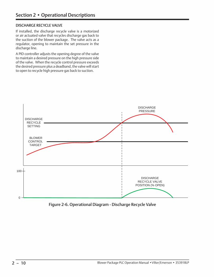
DISCHARGE RECYCLE VALVE
If installed, the discharge recycle valve is a motorized or air actuated valve that recycles discharge gas back to the suction of the blower package. The valve acts as a regulator, opening to maintain the set pressure in the discharge line.
A PID controller adjusts the opening degree of the valve to maintain a desired pressure on the high pressure side of the valve. When the recycle control pressure exceeds the desired pressure plus a deadband, the valve will start to open to recycle high pressure gas back to suction.
3 – 1
Section 3 • Overview Screens
Blower Package PLC Operation Manual •Vilter/Emerson • 35391BLP
Figure 3-1. Basic Blower Package Screen
Blower and System Overview Screens
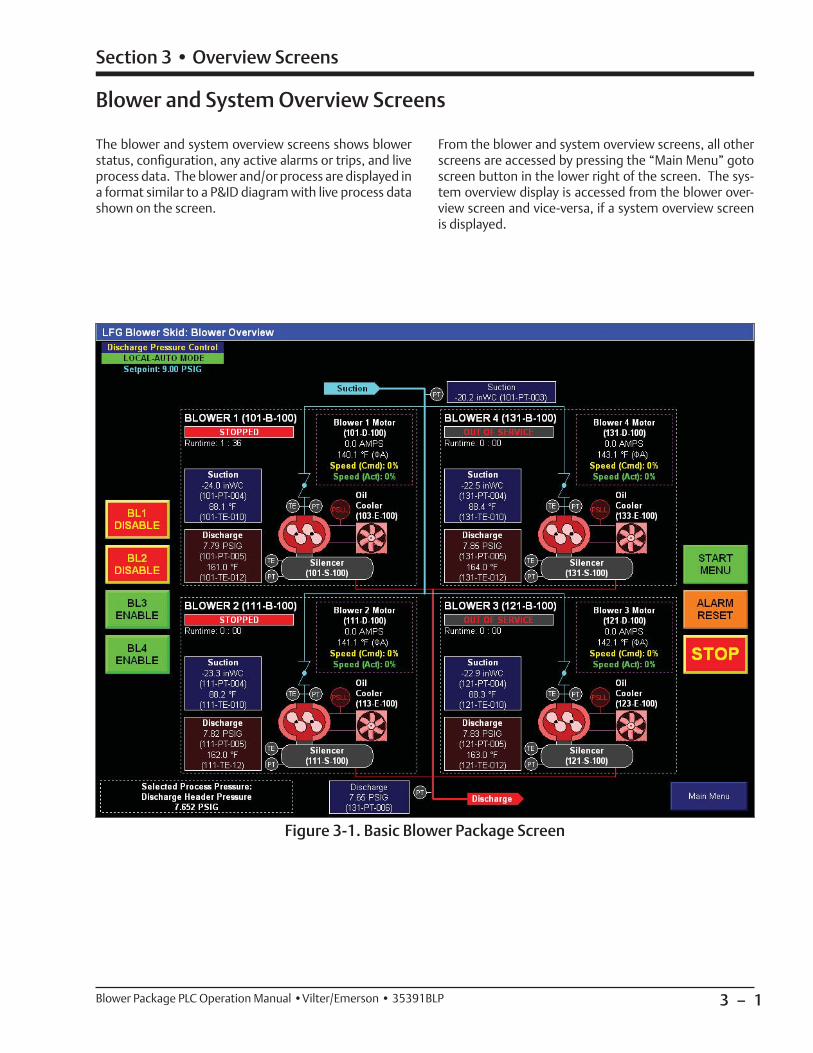
The blower and system overview screens shows blower status, confi guration, any active alarms or trips, and live process data. The blower and/or process are displayed in a format similar to a P&ID diagram with live process data shown on the screen.
From the blower and system overview screens, all other screens are accessed by pressing the “Main Menu” goto screen button in the lower right of the screen. The sys-tem overview display is accessed from the blower over-view screen and vice-versa, if a system overview screen is displayed.

3 – 2 / Blank Blower Package PLC Operation Manual •Vilter/Emerson • 35391BLP

4 – 1
Section 4 • HMI Navigation
Blower Package PLC Operation Manual •Vilter/Emerson • 35391BLP
Main Menu Screen
HMI screens are accessed by using the navigation but-tons on each screen. When the HMI boots up, the blower overview screen is displayed by default. The HMI Screens are divided into groups, all of which are acces-sible from the Main Menu Screen.
Figure 4-1. Main Menu Screen
The Main Menu Screen allows the user to view basic blower confi guration, status, active alarms and trips, as well as navigate to confi guration, control, calibration, and diagnostics screens.
An electronic copy of the blower PLC manual is accessed from the Main Menu Screen.

4 – 2
Section 4 • HMI Navigation
Blower Package PLC Operation Manual •Vilter/Emerson • 35391BLP
HMI Security
Some items and screens on the HMI require a login to be viewed or changed.
Login accounts are described below, each with its de-fault password and level of access.
DEFAULT
• This is the user account that is active when the HMI boots up or the user logs out of another user account.
• Permissions:
• May start and stop the machine
• May change Remote-Local and Auto-Manual modes
• May view setpoints, calibration data, and diagnostics
OP1, OP2, OP3, OP4, OP5
• These user accounts are intended for operators.
• Default Password: 1
• Permissions
• May start and stop the machine
• May change Remote-Local and Auto-Manual modes
• May Operate the machine in Manual mode
• May view setpoints, calibration data, and diagnostics
• May change setpoints
SUPER
• This user account is intended for site supervisors, managers, and superintendents.
• Default Password: 1
• Permissions
• May start and stop the machine
• May change Remote-Local and Auto-Manual modes
• May Operate the machine in Manual mode
• May view setpoints, calibration data, and diagnostics
• May change setpoints
• May force Discrete and Analog outputs on the PLC
• May make changes to machine confi guration selections
LOGGING IN
To log on, press the “Log On” button. The “Log On” but-ton is located in the Upper-Right corner of most screens, and in the lower right corner of the menu screen. The login popup screen will appear, shown in Figure 4-3. Enter User Name and password using the popup keyboard.
It is recommended to log out when fi nished. Every login is recorded in the blower control’s event list. After 10 minutes of inactivity, the HMI will automatically log out the current user.
Figure 4-2. Login Popup Screen

4 – 3
Section 4 • HMI Navigation
Blower Package PLC Operation Manual •Vilter/Emerson • 35391BLP
Figure 4-3. Login Screen Keyboard

4 – 4 / Blank Blower Package PLC Operation Manual •Vilter/Emerson • 35391BLP
5 – 1
Section 5 • Configuration - Supervisor Level
Blower Package PLC Operation Manual •Vilter/Emerson • 35391BLP
Confi guration Screen - Supervisor Level
Figure 5-1. Confi guration Screen - All Options Shown (Supervisor Level)
NOTE
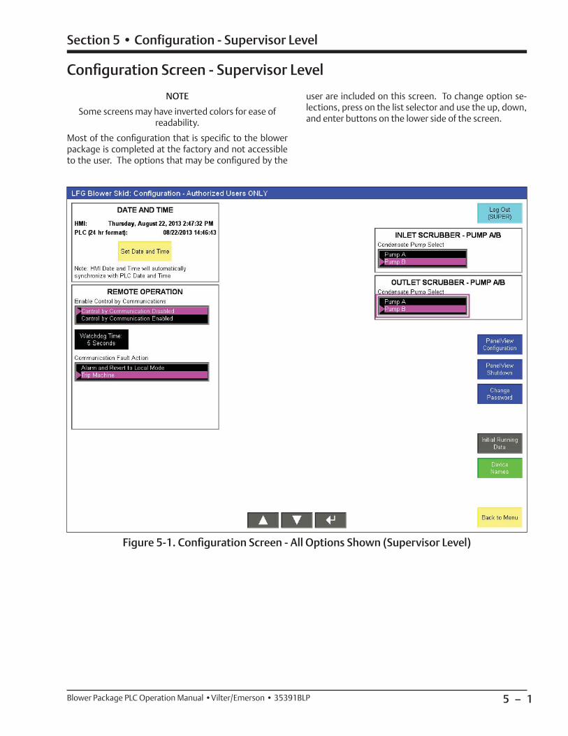
Some screens may have inverted colors for ease of readability.
Most of the confi guration that is specifi c to the blower package is completed at the factory and not accessible to the user. The options that may be confi gured by the
user are included on this screen. To change option se-lections, press on the list selector and use the up, down, and enter buttons on the lower side of the screen.

5 – 2
Section 5 • Configuration - Supervisor Level
Blower Package PLC Operation Manual •Vilter/Emerson • 35391BLP
Figure 5-2. Set Date/Time Pop-Up Screen - Supervisor Level
DATE AND TIME
Allows the Real Time Clock in the PLC to be set. Pressing “Set Date and Time” will bring up the “Set Date and Time” popup screen.
• Date and Time must be set in 24-hour format.
• Pressing “Set Date and Time” will set the PLC time clock.
• The HMI time clock will automatically synchronize to the PLC time clock.
REMOTE OPERATION
For the blower control to accept commands from a DCS or Central Controller, Control by Communications must be enabled. For more details on remote opera-tion, see Section 12, Communication with DCS/Central Controller.
• Control by Communications
• If enabled, allows a central controller/DCS to send commands to the blower PLC
• If disabled, allows a central controller/DCS to read data only.
• Communications Watchdog and Communication Fault Action
• The settable watchdog time defi nes the amount of time a loss in communications can be detected before triggering a communication fault
• Action taken on communication fault is selectable:
• Alarm and Revert to local mode – The blower controller will generate an alarm, and change mode to local-auto. The machine will contin-ue to run (if running) in local mode.
• Trip Machine – Communication Fault will shut the machine down.
MOTOR RTDs
Selects if Motor Winding and Bearing Temperatures are being monitored by the controller.
INLET / OUTLET SCRUBBER PUMP A / B
If the inlet and/or outlet scrubbers include dual conden-sate pumps, this selection determines which pump is active.
CHANGE PASSWORD
Pressing the “Change Password” button opens the “Change Password” pop-up screen, see Figure 5-3 To change a password on an account, the user must be logged in under that account.

5 – 3
Section 5 • Configuration - Supervisor Level
Blower Package PLC Operation Manual •Vilter/Emerson • 35391BLP
Figure 5-3. Change Password Pop-Up Screen - Supervisor Level
PANELVIEW CONFIGURATION
Pressing the “Panelview Confi guration” button closes the blower control application running on the HMI and opens the Factory Talk View ME Station confi guration screens.
INITIAL RUNNING DATA
Pressing the “Initial Running Data” Button opens the Initial Running Data Screen which shows baseline data logged when the blower was new. See Section X “Diagnostics Screens” for more information.
DEVICE NAMES
Pressing the “Device Names” button navigates to the Defi ne Device Names screens. See “Defi ne Device Names” later in this section for more information.
BACK TO MENU
Pressing the “Back to Menu” button navigates back to the main menu screen.

5 – 4
Section 5 • Configuration - Supervisor Level
Blower Package PLC Operation Manual •Vilter/Emerson • 35391BLP
Editing Device Names
The “Device Names” group of screens allows a user logged in as “SUPER” to edit names shown on the screen identifying blower unit and package equipment, instru-mentation, and alarm and trip designations. To edit the text fi elds in this group of screens, press on the string in-put button and use the popup keyboard to edit the text.
Typically, the device names entered in this group of screens are the designations for each device, instru-ment, or alarm that relate it back to the P&ID diagram.
The “Device Names” group of screens is divided into three sections, see Figure 5-3.
Figure 5-4. Defi ne Device Names - Devices and Vessels (Supervisor Level)
DEVICES AND VESSELS
In Figure 5-4, this screen the user may edit device names shown on the screen for devices, vessels, and equipment installed on the blower package.
The user may navigate to other screens within the “Defi ne Device Names” group by using the navigation buttons on the right side of the screen.

5 – 5
Section 5 • Configuration - Supervisor Level
Blower Package PLC Operation Manual •Vilter/Emerson • 35391BLP
INSTRUMENTATION
In Figure 5-5, this screen allows the user to edit device names shown on the screen for instrumentation in-stalled on the blower unit or package.
Figure 5-5. Defi ne Device Names - Instrumentation (Supervisor Level)
5 – 6
Section 5 • Configuration - Supervisor Level
Blower Package PLC Operation Manual •Vilter/Emerson • 35391BLP
ALARM AND TRIP
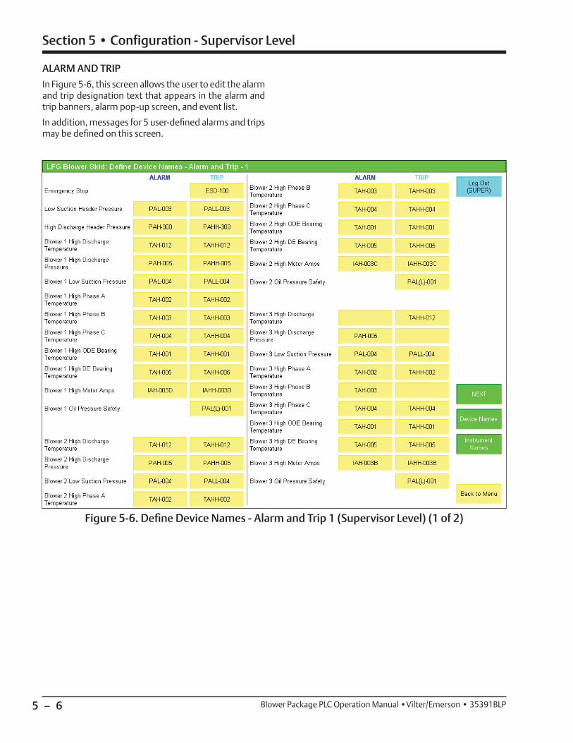
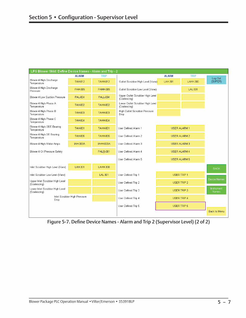
In Figure 5-6, this screen allows the user to edit the alarm and trip designation text that appears in the alarm and trip banners, alarm pop-up screen, and event list.
In addition, messages for 5 user-defi ned alarms and trips may be defi ned on this screen.
Figure 5-6. Defi ne Device Names - Alarm and Trip 1 (Supervisor Level) (1 of 2)
5 – 7
Section 5 • Configuration - Supervisor Level
Blower Package PLC Operation Manual •Vilter/Emerson • 35391BLP
Figure 5-7. Defi ne Device Names - Alarm and Trip 2 (Supervisor Level) (2 of 2)

5 – 8 / Blank Blower Package PLC Operation Manual •Vilter/Emerson • 35391BLP
6 – 1
Section 6 • Instrument Calibration
Blower Package PLC Operation Manual •Vilter/Emerson • 35391BLP
Calibration Main Screen
Figure 6-1. Instrument Calibration Overview Screen
NOTE
Some screens may have inverted colors for ease of readability.
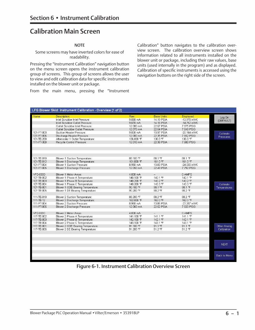
Pressing the “Instrument Calibration” navigation button on the menu screen opens the instrument calibration group of screens. This group of screens allows the user to view and edit calibration data for specifi c instruments installed on the blower unit or package.
From the main menu, pressing the “Instrument
Calibration” button navigates to the calibration over-view screen. The calibration overview screen shows information related to all instruments installed on the blower unit or package, including their raw values, base units (used internally in the program) and as displayed. Calibration of specifi c instruments is accessed using the navigation buttons on the right side of the screen.

6 – 2
Section 6 • Instrument Calibration
Blower Package PLC Operation Manual •Vilter/Emerson • 35391BLP
Pressure Calibration Screen
Figure 6-2. Pressure Calibration Screen - 1 of 3
In Figure 6-2, the temperature calibration group of screens allows the user to change the pressure units displayed on the screen as well as calibrate pressure instruments.
Pressure units are specifi c to individual pressure instru-ments. Changing the pressure display units for a trans-ducer also converts all pressure setpoints related to that transducer to the new selected units.
The following pressure units are available for display:
• PSIG (Pounds/square inch gage)
• PSIA (Pounds/square inch absolute)
• kPa[A] (Kilopascals absolute)
• kPa[G] (Kilopascals gage)
• kg/cm2[A] (Kilograms/square centimeter absolute)
• kg/cm2[G] (Kilograms/square centimeter gage)
• inHg (inches of mercury) – Vacuum is shown in inHg, positive pressure is shown in PSIG
• inWC (gage)
• Bar[A] (absolute)
• Bar[G] (gage)
• Torr[A] (absolute)
• Torr[G] (gage)
6 – 3
Section 6 • Instrument Calibration
Blower Package PLC Operation Manual •Vilter/Emerson • 35391BLP
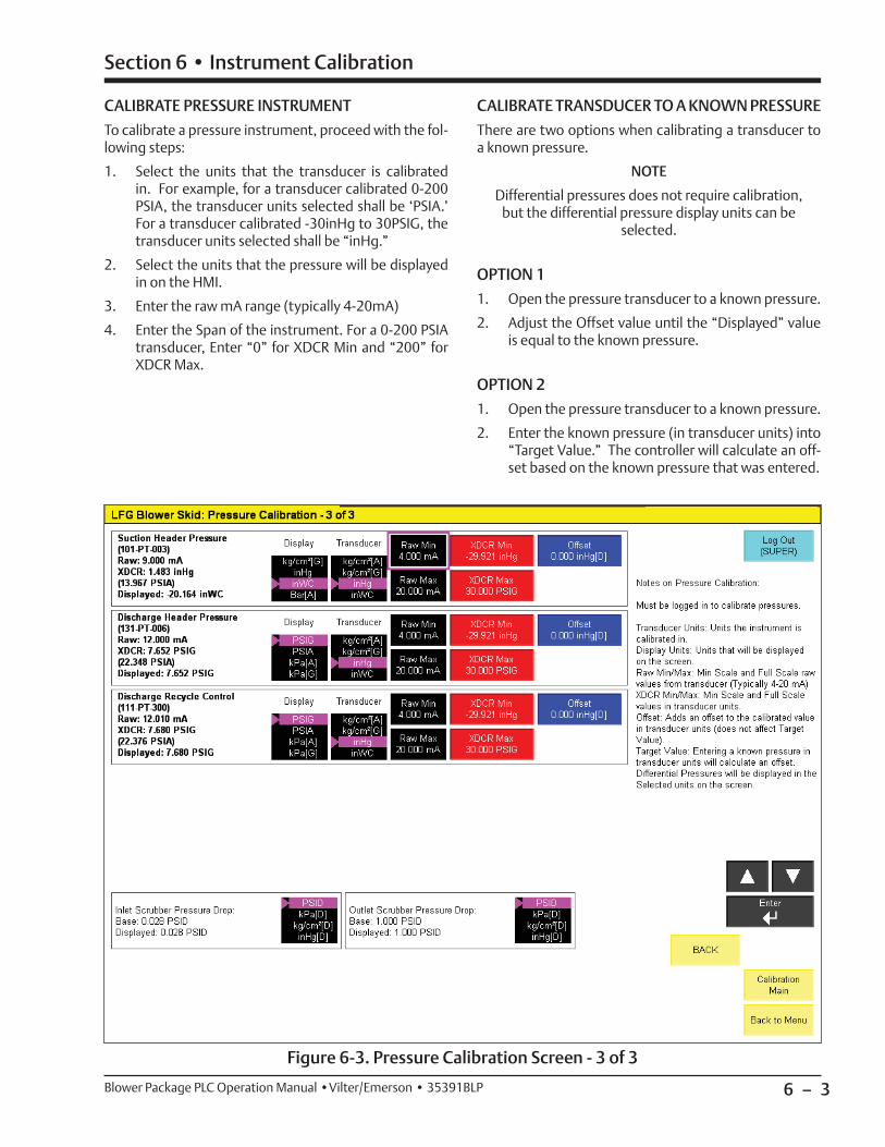
Figure 6-3. Pressure Calibration Screen - 3 of 3
CALIBRATE PRESSURE INSTRUMENT
To calibrate a pressure instrument, proceed with the fol-lowing steps:
1. Select the units that the transducer is calibrated in. For example, for a transducer calibrated 0-200 PSIA, the transducer units selected shall be ‘PSIA.’ For a transducer calibrated -30inHg to 30PSIG, the transducer units selected shall be “inHg.”
2. Select the units that the pressure will be displayed in on the HMI.
3. Enter the raw mA range (typically 4-20mA)
4. Enter the Span of the instrument. For a 0-200 PSIA transducer, Enter “0” for XDCR Min and “200” for XDCR Max.
CALIBRATE TRANSDUCER TO A KNOWN PRESSURE
There are two options when calibrating a transducer to a known pressure.
NOTE
Differential pressures does not require calibration, but the differential pressure display units can be
selected.
OPTION 1
1. Open the pressure transducer to a known pressure.
2. Adjust the Offset value until the “Displayed” value is equal to the known pressure.
OPTION 2
1. Open the pressure transducer to a known pressure.
2. Enter the known pressure (in transducer units) into “Target Value.” The controller will calculate an off-set based on the known pressure that was entered.

6 – 4
Section 6 • Instrument Calibration
Blower Package PLC Operation Manual •Vilter/Emerson • 35391BLP
Figure 6-4. Temperature Calibration Screen
The temperature calibration group of screens allows the user to change the temperature units displayed on the screen as well as calibrate temperature instruments.
Four Temperature units are available for display:
• Fahrenheit
• Celsius or Centigrade
• Kelvin (Absolute Celsius temperature scale)
• Rankine (Absolute Fahrenheit temperature scale)
Temperature units can be changed by touching on the list selector in any temperature calibration screen and using the up, down, and enter buttons. Changing the temperature display units also converts all temperature setpoints to the new selected units.
CALIBRATE TEMPERATURE INSTRUMENTS
There two types of temperature instruments that can be calibrated, RTDs and temperature transmitters.
To calibrate an RTD, proceed with the following steps.NOTE
Typically, RTDs are very accurate and do not require calibration.
1. Expose the RTD to a known temperature (such as a slurry of crushed ice and water).
2. Enter an offset so the displayed temperature is equal to the known temperature.
To calibrate a temperature transmitter, proceed with the following steps.1. Enter the raw mA range (typically 4-20mA).
2. Enter the span of the transmitter in degrees Fahrenheit. For a 32-392 Fahrenheit transmitter, Enter “32” for XDCR Min and “392” for XDCR Max.
Temperature Calibration Screen
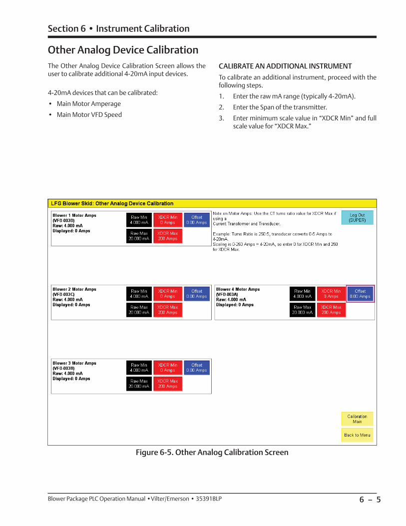
6 – 5
Section 6 • Instrument Calibration
Blower Package PLC Operation Manual •Vilter/Emerson • 35391BLP
The Other Analog Device Calibration Screen allows the user to calibrate additional 4-20mA input devices.
4-20mA devices that can be calibrated:
• Main Motor Amperage
• Main Motor VFD Speed
CALIBRATE AN ADDITIONAL INSTRUMENT
To calibrate an additional instrument, proceed with the following steps.
1. Enter the raw mA range (typically 4-20mA).
2. Enter the Span of the transmitter.
3. Enter minimum scale value in “XDCR Min” and full scale value for “XDCR Max.”
Other Analog Device Calibration
Figure 6-5. Other Analog Calibration Screen

6 – 6 / Blank Blower Package PLC Operation Manual •Vilter/Emerson • 35391BLP
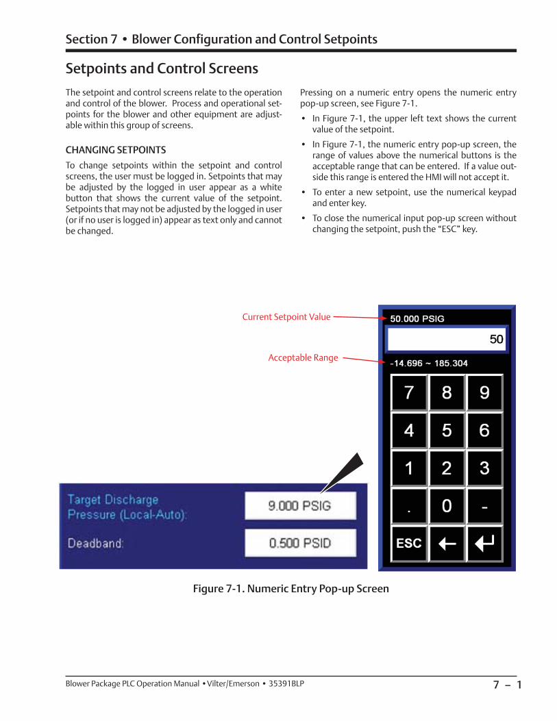
7 – 1
Section 7 • Blower Configuration and Control Setpoints
Blower Package PLC Operation Manual •Vilter/Emerson • 35391BLP
Setpoints and Control Screens
The setpoint and control screens relate to the operation and control of the blower. Process and operational set-points for the blower and other equipment are adjust-able within this group of screens.
CHANGING SETPOINTS
To change setpoints within the setpoint and control screens, the user must be logged in. Setpoints that may be adjusted by the logged in user appear as a white button that shows the current value of the setpoint. Setpoints that may not be adjusted by the logged in user (or if no user is logged in) appear as text only and cannot be changed.
Figure 7-1. Numeric Entry Pop-up Screen
Pressing on a numeric entry opens the numeric entry pop-up screen, see Figure 7-1.
• In Figure 7-1, the upper left text shows the current value of the setpoint.
• In Figure 7-1, the numeric entry pop-up screen, the range of values above the numerical buttons is the acceptable range that can be entered. If a value out-side this range is entered the HMI will not accept it.
• To enter a new setpoint, use the numerical keypad and enter key.
• To close the numerical input pop-up screen without changing the setpoint, push the “ESC” key.
Current Setpoint Value
Acceptable Range
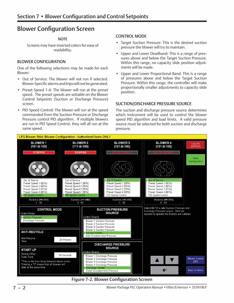
7 – 2
Section 7 • Blower Configuration and Control Setpoints
Blower Package PLC Operation Manual •Vilter/Emerson • 35391BLP
Figure 7-2. Blower Confi guration Screen
NOTE
Screens may have inverted colors for ease of readability.
BLOWER CONFIGURATION
One of the following selections may be made for each Blower:
• Out of Service: The blower will not run if selected. Blower-Specifi c alarms and trips will not be generated.
• Preset Speed 1-4: The blower will run at the preset speed. The preset speeds are settable on the Blower Control Setpoints (Suction or Discharge Pressure) screen.
• PID Speed Control: The blower will run at the speed commanded from the Suction Pressure or Discharge Pressure control PID algorithm. If multiple blowers are run in PID Speed Control, they will all run at the same speed.
CONTROL MODE
• Target Suction Pressure: This is the desired suction pressure the blower will try to maintain.
• Upper and Lower Deadband: This is a range of pres-sures above and below the Target Suction Pressure. Within this range, no capacity slide position adjust-ments will be made.
• Upper and Lower Proportional Band: This is a range of pressures above and below the Target Suction Pressure. Within this range, the controller will make proportionally smaller adjustments to capacity slide position.
SUCTION/DISCHARGE PRESSURE SOURCE
The suction and discharge pressure source determines which instrument will be used to control the blower speed PID algorithm and load limits. A valid pressure source must be selected for both suction and discharge pressure.
Blower Confi guration Screen
7 – 3
Section 7 • Blower Configuration and Control Setpoints
Blower Package PLC Operation Manual •Vilter/Emerson • 35391BLP
• If suction pressure control is selected, the selected suction pressure source will control the blower speed command, and the selected discharge pressure source will control load limiting and forced unloading.
• If discharge pressure control is selected, the selected discharge pressure source will control the blower speed command, and the selected suction pressure source will control load limiting and forced unloading.
ANTI-RECYCLE
After a blower motor stops, the anti-recycle function will become active. The motor will not be allowed to re-start until the anti-recycle time is up. The anti-recycle func-tion is blower specifi c: one blower in anti-recycle will not affect the other blowers on the package. If the blower package is started and a blower confi gured to run is in anti-recycle, that blower will start once the anti-recycle timer is up.
START UP
When multiple blowers are starting up, they start se-quentially and increase in order. The offset dwell time is what determines the amount of delay between starting each individual blower. The purpose of this function is to reduce the load on the electrical infrastructure when necessary. Setting this time to “0” means that all blow-ers confi gured to run will start at the same time.
In order to be able to start the blower package, the blow-er confi guration must be valid. For the blower confi gura-tion to be valid, all of the following rules must be met:
• At least one blower must be in service (selected to run in preset speed or PID Speed Control).
• The selected suction and discharge pressure source must be valid based on the confi guration of the pack-age. (Example: to select a header pressure transduc-er as a control source, the header pressure transducer must be installed, to select a blower suction or dis-charge pressure transducer as a control source, that particular blower must be in service.
Blower Control Setpoints - Suction Pressure
The Blower Control Setpoints page 1 (Suction Pressure) screen appears when navigating to “Blower Control Setpoints” from the menu screen when Suction Pressure control is selected. Setpoints for desired suction pres-sure, PID Tuning, and Load Limits are accessible from this screen. For more information and operational de-scriptions, see section 2 “Operational Descriptions.”
SUCTION PRESSURE CONTROL
• Target Suction Pressure: This is the desired suction pressure the blower will try to maintain.
• Deadband: This is a range of pressures above and be-low the Target Suction Pressure. Within this range, no speed adjustments will be made.
PID TUNING
• Loop Update Time: This is the cycle time of the PID controller.
• Proportional Gain (Kp): This is the proportional con-stant of the PID calculation.
• Integral Gain (Ki): This is the integral constant of the PID calculation.
• Derivative Gain (Kd): This is the derivative constant of the PID calculation.
HIGH DISCHARGE PRESSURE LOAD LIMITS
• Inhibit Loading: Blower will not be allowed to increase speed if Discharge Pressure rises above this setpoint.
• Unload At: Blower will begin continuously decreasing speed if Discharge Pressure rises above this setpoint.
• Unload To: If forced unloading is active, the blower will unload continuously until Discharge Pressure reaches this setpoint.
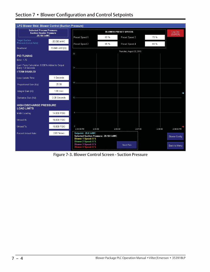
7 – 4
Section 7 • Blower Configuration and Control Setpoints
Blower Package PLC Operation Manual •Vilter/Emerson • 35391BLP
Figure 7-3. Blower Control Screen - Suction Pressure

7 – 5
Section 7 • Blower Configuration and Control Setpoints
Blower Package PLC Operation Manual •Vilter/Emerson • 35391BLP
Figure 7-4. Blower Control Screen - Discharge Pressure
Blower Control Setpoints - Discharge Pressure
The Blower Control Setpoints page 1 (Discharge Pressure) screen appears when navigating to “Blower Control Setpoints” from the menu screen when Discharge Pressure control is selected. Setpoints for desired discharge pressure, PID Tuning, and Load Limits are accessible from this screen. For more information and operational descriptions, see section 2 “Operational Descriptions.”
DISCHARGE PRESSURE CONTROL
• Target Discharge Pressure: This is the desired suction pressure the blower will try to maintain.
• Deadband: This is a range of pressures above and be-low the Target Suction Pressure. Within this range, no speed adjustments will be made.
PID TUNING
• Loop Update Time: This is the cycle time of the PID
controller.
• Proportional Gain (Kp): This is the proportional con-stant of the PID calculation.
• Integral Gain (Ki): This is the integral constant of the PID calculation.
• Derivative Gain (Kd): This is the derivative constant of the PID calculation.
LOW SUCTION PRESSURE LOAD LIMITS
• Inhibit Loading: Blower will not be allowed to increase speed if Suction Pressure falls below this setpoint.
• Unload At: Blower will begin continuously decreasing speed if Suction Pressure falls below this setpoint.
• Unload To: If forced unloading is active, the blower will decrease its speed continuously until Suction Pressure reaches this setpoint.

7 – 6 / Blank Blower Package PLC Operation Manual •Vilter/Emerson • 35391BLP
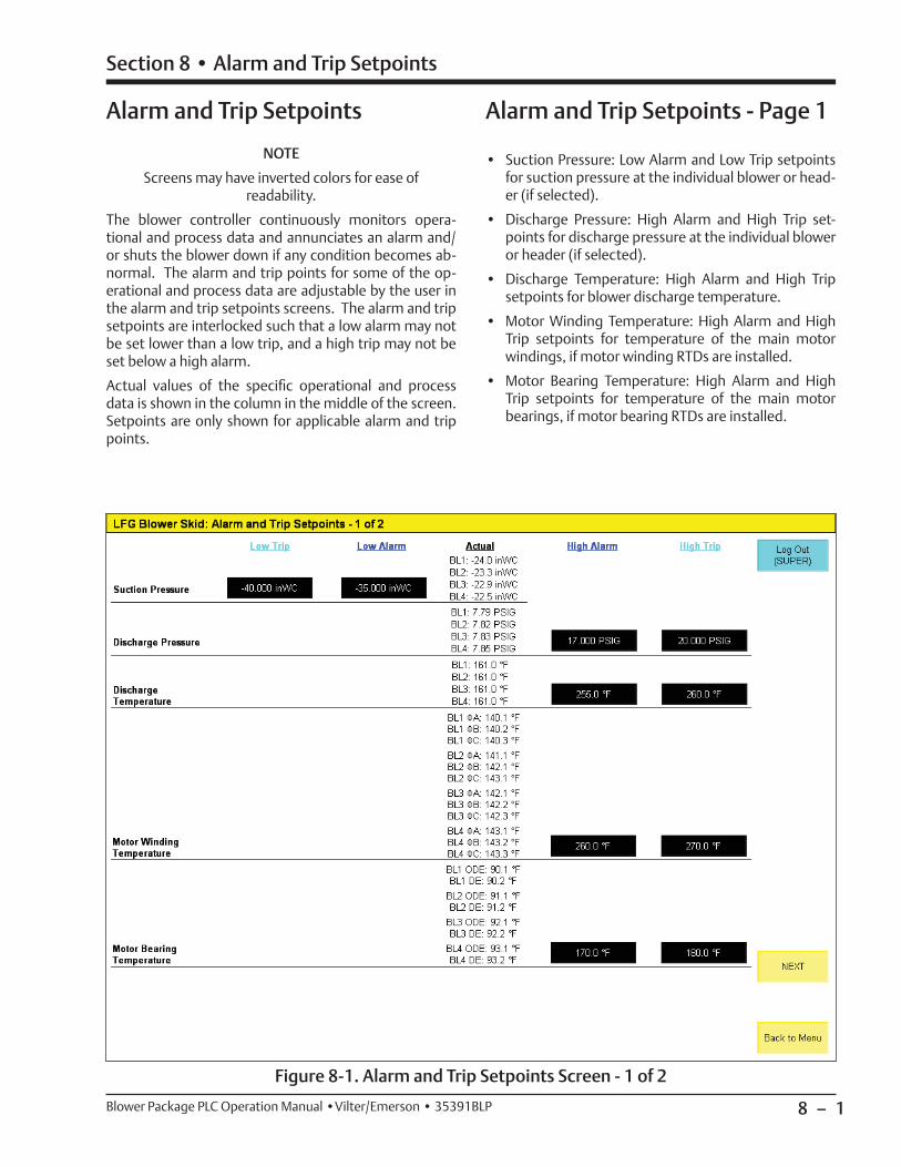
8 – 1
Section 8 • Alarm and Trip Setpoints
Blower Package PLC Operation Manual •Vilter/Emerson • 35391BLP
Alarm and Trip Setpoints
Figure 8-1. Alarm and Trip Setpoints Screen - 1 of 2
NOTE
Screens may have inverted colors for ease of readability.
The blower controller continuously monitors opera-tional and process data and annunciates an alarm and/or shuts the blower down if any condition becomes ab-normal. The alarm and trip points for some of the op-erational and process data are adjustable by the user in the alarm and trip setpoints screens. The alarm and trip setpoints are interlocked such that a low alarm may not be set lower than a low trip, and a high trip may not be set below a high alarm.
Actual values of the specifi c operational and process data is shown in the column in the middle of the screen. Setpoints are only shown for applicable alarm and trip points.
Alarm and Trip Setpoints - Page 1
• Suction Pressure: Low Alarm and Low Trip setpoints for suction pressure at the individual blower or head-er (if selected).
• Discharge Pressure: High Alarm and High Trip set-points for discharge pressure at the individual blower or header (if selected).
• Discharge Temperature: High Alarm and High Trip setpoints for blower discharge temperature.
• Motor Winding Temperature: High Alarm and High Trip setpoints for temperature of the main motor windings, if motor winding RTDs are installed.
• Motor Bearing Temperature: High Alarm and High Trip setpoints for temperature of the main motor bearings, if motor bearing RTDs are installed.
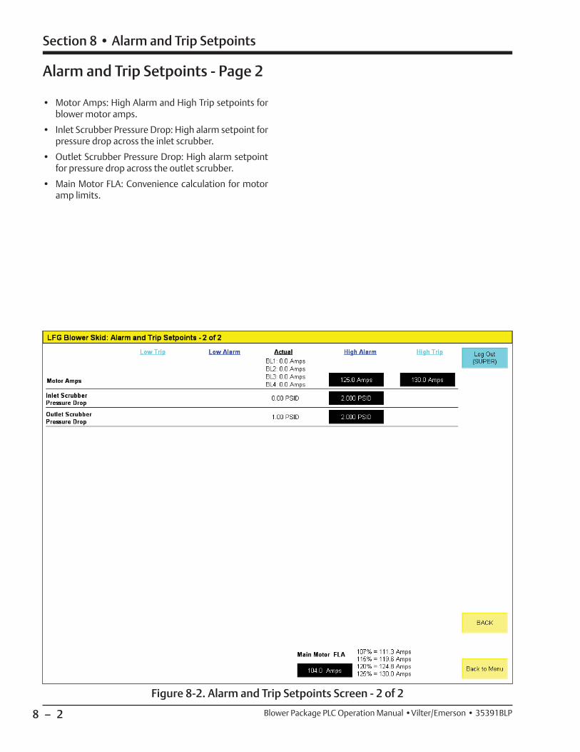
8 – 2
Section 8 • Alarm and Trip Setpoints
Blower Package PLC Operation Manual •Vilter/Emerson • 35391BLP
Figure 8-2. Alarm and Trip Setpoints Screen - 2 of 2
Alarm and Trip Setpoints - Page 2
• Motor Amps: High Alarm and High Trip setpoints for blower motor amps.
• Inlet Scrubber Pressure Drop: High alarm setpoint for pressure drop across the inlet scrubber.
• Outlet Scrubber Pressure Drop: High alarm setpoint for pressure drop across the outlet scrubber.
• Main Motor FLA: Convenience calculation for motor amp limits.
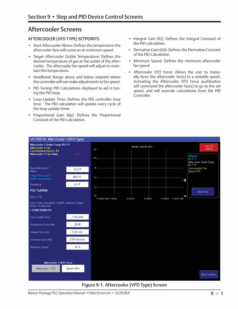
9 – 1
Section 9 • Step and PID Device Control Screens
Blower Package PLC Operation Manual •Vilter/Emerson • 35391BLP
Figure 9-1. Aftercooler (VFD Type) Screen
AFTERCOOLER (VFD TYPE) SETPOINTS
• Start Aftercooler Above: Defi nes the temperature the aftercooler fans will come on at minimum speed.
• Target Aftercooler Outlet Temperature: Defi nes the desired temperature of gas at the outlet of the after-cooler. The aftercooler fan speed will adjust to main-tain this temperature.
• Deadband: Range above and below setpoint where the controller will not make adjustments to fan speed.
• PID Tuning: PID Calculations displayed to aid in tun-ing the PID loop.
• Loop Update Time: Defi nes the PID controller loop time. The PID calculation will update every cycle of the loop update timer.
• Proportional Gain (Kp): Defi nes the Proportional Constant of the PID calculation.
• Integral Gain (Ki): Defi nes the Integral Constant of the PID calculation.
• Derivative Gain (Kd): Defi nes the Derivative Constant of the PID Calculation.
• Minimum Speed: Defi nes the minimum aftercooler fan speed.
• Aftercooler VFD Force: Allows the user to manu-ally force the aftercooler fan(s) to a settable speed. Activating the Aftercooler VFD Force pushbutton will command the aftercooler fan(s) to go to the set speed, and will override calculations from the PID Controller.
Aftercooler Screens
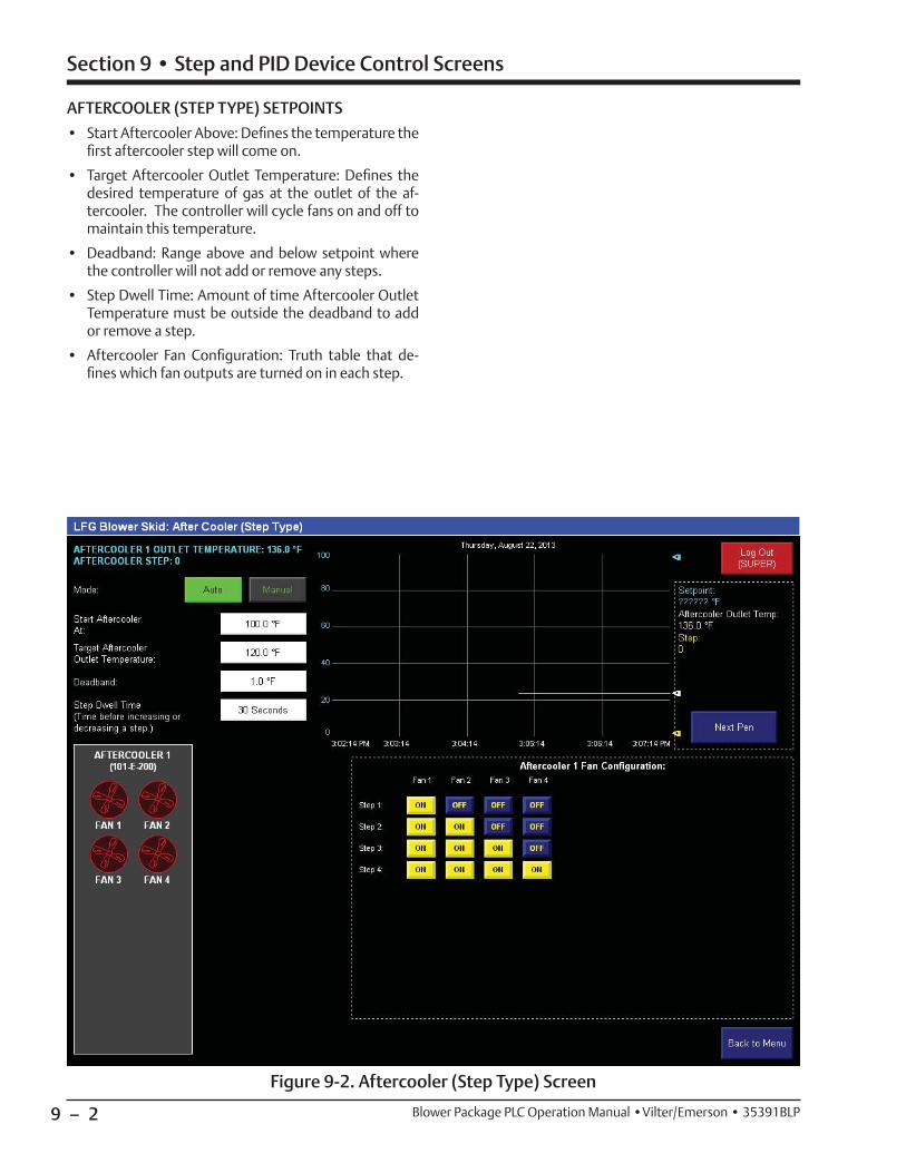
9 – 2
Section 9 • Step and PID Device Control Screens
Blower Package PLC Operation Manual •Vilter/Emerson • 35391BLP
Figure 9-2. Aftercooler (Step Type) Screen
AFTERCOOLER (STEP TYPE) SETPOINTS
• Start Aftercooler Above: Defi nes the temperature the fi rst aftercooler step will come on.
• Target Aftercooler Outlet Temperature: Defi nes the desired temperature of gas at the outlet of the af-tercooler. The controller will cycle fans on and off to maintain this temperature.
• Deadband: Range above and below setpoint where the controller will not add or remove any steps.
• Step Dwell Time: Amount of time Aftercooler Outlet Temperature must be outside the deadband to add or remove a step.
• Aftercooler Fan Confi guration: Truth table that de-fi nes which fan outputs are turned on in each step.
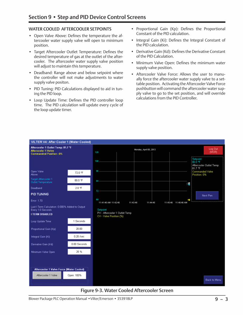
9 – 3
Section 9 • Step and PID Device Control Screens
Blower Package PLC Operation Manual •Vilter/Emerson • 35391BLP
Figure 9-3. Water Cooled Aftercooler Screen
WATER COOLED AFTERCOOLER SETPOINTS
• Open Valve Above: Defi nes the temperature the af-tercooler water supply valve will open to minimum position.
• Target Aftercooler Outlet Temperature: Defi nes the desired temperature of gas at the outlet of the after-cooler. The aftercooler water supply valve position will adjust to maintain this temperature.
• Deadband: Range above and below setpoint where the controller will not make adjustments to water supply valve positon.
• PID Tuning: PID Calculations displayed to aid in tun-ing the PID loop.
• Loop Update Time: Defi nes the PID controller loop time. The PID calculation will update every cycle of the loop update timer.
• Proportional Gain (Kp): Defi nes the Proportional Constant of the PID calculation.
• Integral Gain (Ki): Defi nes the Integral Constant of the PID calculation.
• Derivative Gain (Kd): Defi nes the Derivative Constant of the PID Calculation.
• Minimum Valve Open: Defi nes the minimum water supply valve position.
• Aftercooler Valve Force: Allows the user to manu-ally force the aftercooler water supply valve to a set-table position. Activating the Aftercooler Valve Force pushbutton will command the aftercooler water sup-ply valve to go to the set position, and will override calculations from the PID Controller.
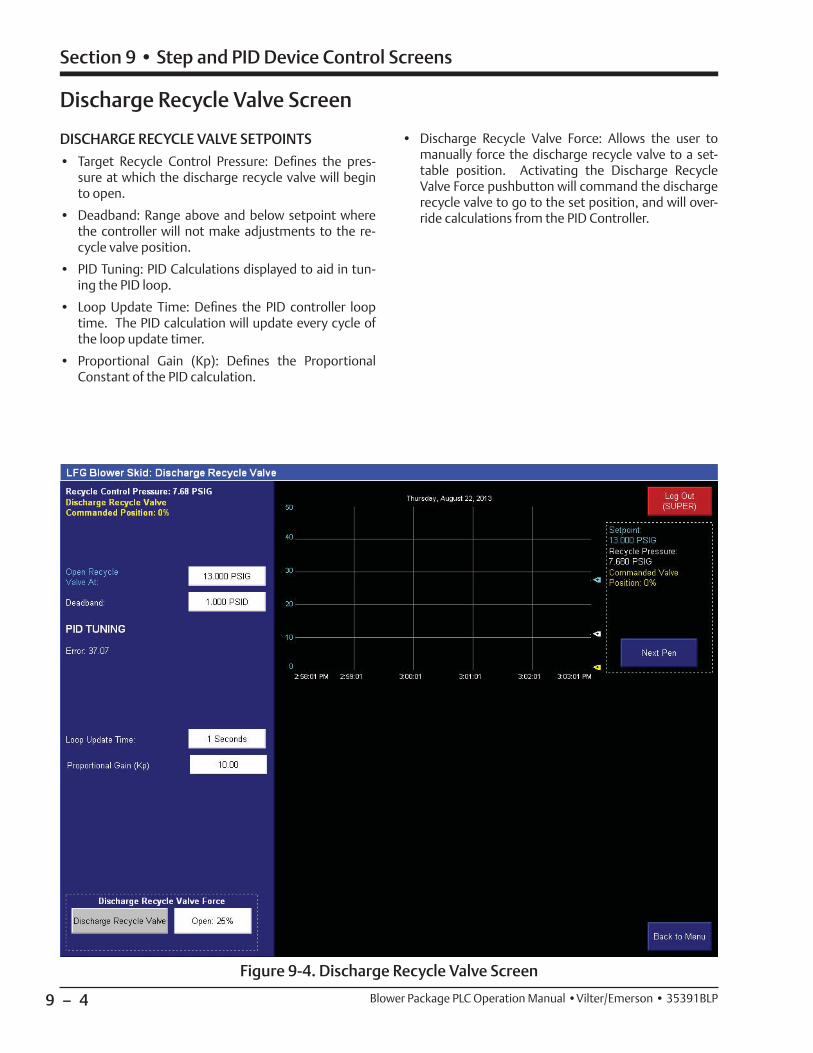
9 – 4
Section 9 • Step and PID Device Control Screens
Blower Package PLC Operation Manual •Vilter/Emerson • 35391BLP
Figure 9-4. Discharge Recycle Valve Screen
Discharge Recycle Valve Screen
DISCHARGE RECYCLE VALVE SETPOINTS
• Target Recycle Control Pressure: Defi nes the pres-sure at which the discharge recycle valve will begin to open.
• Deadband: Range above and below setpoint where the controller will not make adjustments to the re-cycle valve position.
• PID Tuning: PID Calculations displayed to aid in tun-ing the PID loop.
• Loop Update Time: Defi nes the PID controller loop time. The PID calculation will update every cycle of the loop update timer.
• Proportional Gain (Kp): Defi nes the Proportional Constant of the PID calculation.
• Discharge Recycle Valve Force: Allows the user to manually force the discharge recycle valve to a set-table position. Activating the Discharge Recycle Valve Force pushbutton will command the discharge recycle valve to go to the set position, and will over-ride calculations from the PID Controller.
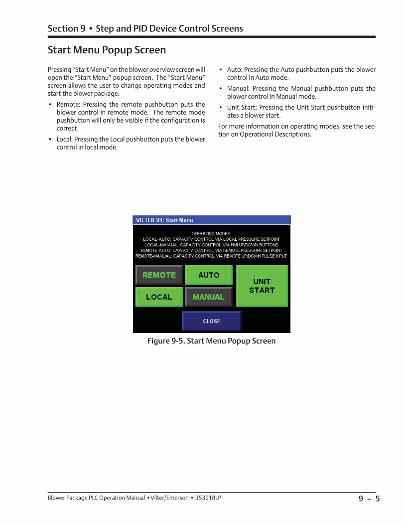
9 – 5
Section 9 • Step and PID Device Control Screens
Blower Package PLC Operation Manual •Vilter/Emerson • 35391BLP
Start Menu Popup Screen
Figure 9-5. Start Menu Popup Screen
Pressing “Start Menu” on the blower overview screen will open the “Start Menu” popup screen. The “Start Menu” screen allows the user to change operating modes and start the blower package.
• Remote: Pressing the remote pushbutton puts the blower control in remote mode. The remote mode pushbutton will only be visible if the confi guration is correct
• Local: Pressing the Local pushbutton puts the blower control in local mode.
• Auto: Pressing the Auto pushbutton puts the blower control in Auto mode.
• Manual: Pressing the Manual pushbutton puts the blower control in Manual mode.
• Unit Start: Pressing the Unit Start pushbutton initi-ates a blower start.
For more information on operating modes, see the sec-tion on Operational Descriptions.

9 – 6 / Blank Blower Package PLC Operation Manual •Vilter/Emerson • 35391BLP
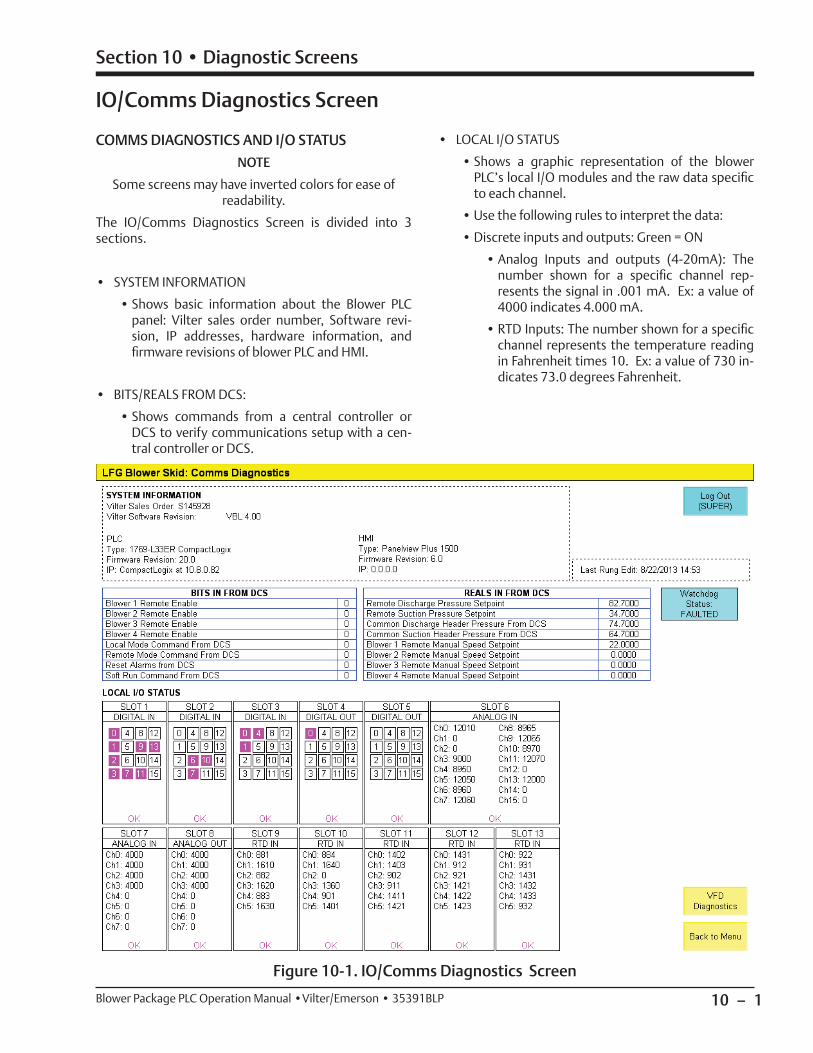
10 – 1
Section 10 • Diagnostic Screens
Blower Package PLC Operation Manual •Vilter/Emerson • 35391BLP
IO/Comms Diagnostics Screen
Figure 10-1. IO/Comms Diagnostics Screen
COMMS DIAGNOSTICS AND I/O STATUS
NOTE
Some screens may have inverted colors for ease of readability.
The IO/Comms Diagnostics Screen is divided into 3 sections.
• SYSTEM INFORMATION
• Shows basic information about the Blower PLC panel: Vilter sales order number, Software revi-sion, IP addresses, hardware information, and fi rmware revisions of blower PLC and HMI.
• BITS/REALS FROM DCS:
• Shows commands from a central controller or DCS to verify communications setup with a cen-tral controller or DCS.
• LOCAL I/O STATUS
• Shows a graphic representation of the blower PLC’s local I/O modules and the raw data specifi c to each channel.
• Use the following rules to interpret the data:
• Discrete inputs and outputs: Green = ON
• Analog Inputs and outputs (4-20mA): The number shown for a specifi c channel rep-resents the signal in .001 mA. Ex: a value of 4000 indicates 4.000 mA.
• RTD Inputs: The number shown for a specifi c channel represents the temperature reading in Fahrenheit times 10. Ex: a value of 730 in-dicates 73.0 degrees Fahrenheit.
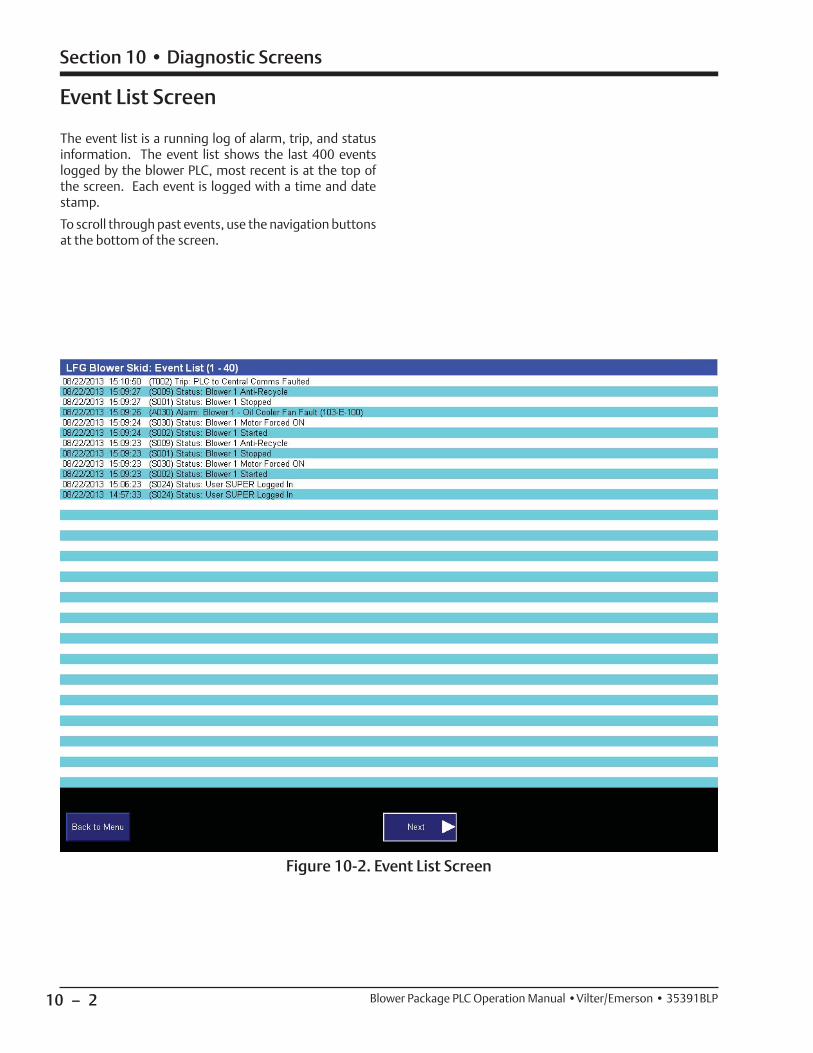
10 – 2
Section 10 • Diagnostic Screens
Blower Package PLC Operation Manual •Vilter/Emerson • 35391BLP
Event List Screen
Figure 10-2. Event List Screen
The event list is a running log of alarm, trip, and status information. The event list shows the last 400 events logged by the blower PLC, most recent is at the top of the screen. Each event is logged with a time and date stamp.
To scroll through past events, use the navigation buttons at the bottom of the screen.
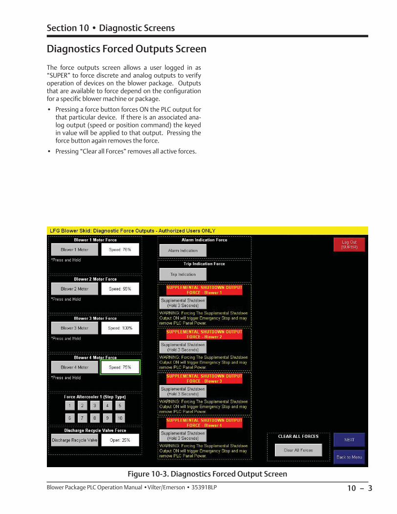
10 – 3
Section 10 • Diagnostic Screens
Blower Package PLC Operation Manual •Vilter/Emerson • 35391BLP
Diagnostics Forced Outputs Screen
Figure 10-3. Diagnostics Forced Output Screen
The force outputs screen allows a user logged in as “SUPER” to force discrete and analog outputs to verify operation of devices on the blower package. Outputs that are available to force depend on the confi guration for a specifi c blower machine or package.
• Pressing a force button forces ON the PLC output for that particular device. If there is an associated ana-log output (speed or position command) the keyed in value will be applied to that output. Pressing the force button again removes the force.
• Pressing “Clear all Forces” removes all active forces.

10 – 4
Section 10 • Diagnostic Screens
Blower Package PLC Operation Manual •Vilter/Emerson • 35391BLP
Captured Data at Shutdown Screen
Figure 10-4. Captured Data at Shutdown Screen
The captured data at shutdown screen shows process and operational data at the time the blower shuts down. Data from the last 5 shutdowns are logged. Each shut-down is given a time and date stamp. The most recent shutdown is on the left.
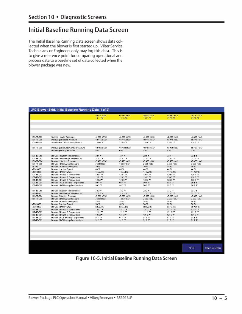
10 – 5
Section 10 • Diagnostic Screens
Blower Package PLC Operation Manual •Vilter/Emerson • 35391BLP
Initial Baseline Running Data Screen
The Initial Baseline Running Data screen shows data col-lected when the blower is fi rst started up. Vilter Service Technicians or Engineers only may log this data. This is to give a reference point for comparing operational and process data to a baseline set of data collected when the blower package was new.
Figure 10-5. Initial Baseline Running Data Screen

10 – 6 / Blank Blower Package PLC Operation Manual •Vilter/Emerson • 35391BLP
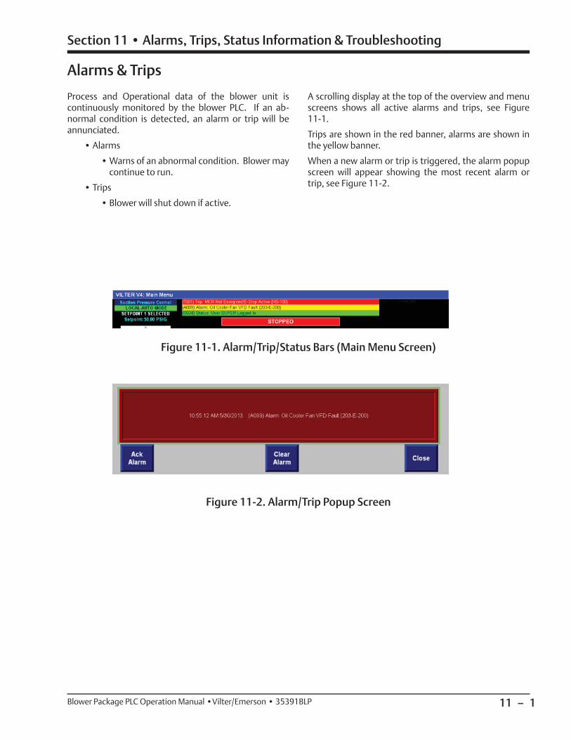
11 – 1
Section 11 • Alarms, Trips, Status Information & Troubleshooting
Blower Package PLC Operation Manual •Vilter/Emerson • 35391BLP
Alarms & Trips
Process and Operational data of the blower unit is continuously monitored by the blower PLC. If an ab-normal condition is detected, an alarm or trip will be annunciated.
• Alarms
• Warns of an abnormal condition. Blower may continue to run.
• Trips
• Blower will shut down if active.
A scrolling display at the top of the overview and menu screens shows all active alarms and trips, see Figure 11-1.
Trips are shown in the red banner, alarms are shown in the yellow banner.
When a new alarm or trip is triggered, the alarm popup screen will appear showing the most recent alarm or trip, see Figure 11-2.
Figure 11-1. Alarm/Trip/Status Bars (Main Menu Screen)
Figure 11-2. Alarm/Trip Popup Screen
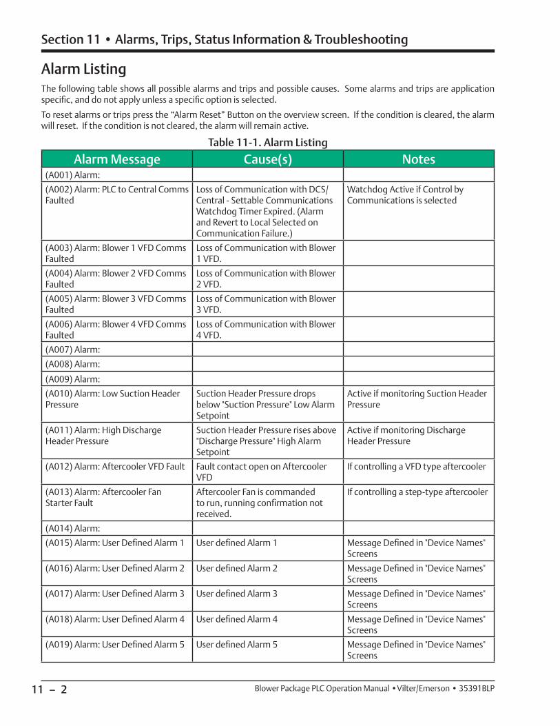
11 – 2
Section 11 • Alarms, Trips, Status Information & Troubleshooting
Blower Package PLC Operation Manual •Vilter/Emerson • 35391BLP
Alarm Message Cause(s) Notes(A001) Alarm:
(A002) Alarm: PLC to Central Comms Faulted
Loss of Communication with DCS/Central - Settable Communications Watchdog Timer Expired. (Alarm and Revert to Local Selected on Communication Failure.)
Watchdog Active if Control by Communications is selected
(A003) Alarm: Blower 1 VFD Comms Faulted
Loss of Communication with Blower 1 VFD.
(A004) Alarm: Blower 2 VFD Comms Faulted
Loss of Communication with Blower 2 VFD.
(A005) Alarm: Blower 3 VFD Comms Faulted
Loss of Communication with Blower 3 VFD.
(A006) Alarm: Blower 4 VFD Comms Faulted
Loss of Communication with Blower 4 VFD.
(A007) Alarm:
(A008) Alarm:
(A009) Alarm:
(A010) Alarm: Low Suction Header Pressure
Suction Header Pressure drops below "Suction Pressure" Low Alarm Setpoint
Active if monitoring Suction Header Pressure
(A011) Alarm: High Discharge Header Pressure
Suction Header Pressure rises above "Discharge Pressure" High Alarm Setpoint
Active if monitoring Discharge Header Pressure
(A012) Alarm: Aftercooler VFD Fault Fault contact open on Aftercooler VFD
If controlling a VFD type aftercooler
(A013) Alarm: Aftercooler Fan Starter Fault
Aftercooler Fan is commanded to run, running confi rmation not received.
If controlling a step-type aftercooler
(A014) Alarm:
(A015) Alarm: User Defi ned Alarm 1 User defi ned Alarm 1 Message Defi ned in "Device Names" Screens
(A016) Alarm: User Defi ned Alarm 2 User defi ned Alarm 2 Message Defi ned in "Device Names" Screens
(A017) Alarm: User Defi ned Alarm 3 User defi ned Alarm 3 Message Defi ned in "Device Names" Screens
(A018) Alarm: User Defi ned Alarm 4 User defi ned Alarm 4 Message Defi ned in "Device Names" Screens
(A019) Alarm: User Defi ned Alarm 5 User defi ned Alarm 5 Message Defi ned in "Device Names" Screens
Table 11-1. Alarm Listing
Alarm ListingThe following table shows all possible alarms and trips and possible causes. Some alarms and trips are application specifi c, and do not apply unless a specifi c option is selected.
To reset alarms or trips press the “Alarm Reset” Button on the overview screen. If the condition is cleared, the alarm will reset. If the condition is not cleared, the alarm will remain active.
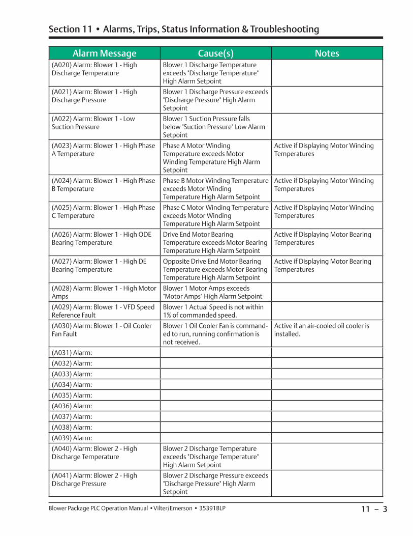
11 – 3
Section 11 • Alarms, Trips, Status Information & Troubleshooting
Blower Package PLC Operation Manual •Vilter/Emerson • 35391BLP
Alarm Message Cause(s) Notes(A020) Alarm: Blower 1 - High Discharge Temperature
Blower 1 Discharge Temperature exceeds "Discharge Temperature" High Alarm Setpoint
(A021) Alarm: Blower 1 - High Discharge Pressure
Blower 1 Discharge Pressure exceeds "Discharge Pressure" High Alarm Setpoint
(A022) Alarm: Blower 1 - Low Suction Pressure
Blower 1 Suction Pressure falls below "Suction Pressure" Low Alarm Setpoint
(A023) Alarm: Blower 1 - High Phase A Temperature
Phase A Motor Winding Temperature exceeds Motor Winding Temperature High Alarm Setpoint
Active if Displaying Motor Winding Temperatures
(A024) Alarm: Blower 1 - High Phase B Temperature
Phase B Motor Winding Temperature exceeds Motor Winding Temperature High Alarm Setpoint
Active if Displaying Motor Winding Temperatures
(A025) Alarm: Blower 1 - High Phase C Temperature
Phase C Motor Winding Temperature exceeds Motor Winding Temperature High Alarm Setpoint
Active if Displaying Motor Winding Temperatures
(A026) Alarm: Blower 1 - High ODE Bearing Temperature
Drive End Motor Bearing Temperature exceeds Motor Bearing Temperature High Alarm Setpoint
Active if Displaying Motor Bearing Temperatures
(A027) Alarm: Blower 1 - High DE Bearing Temperature
Opposite Drive End Motor Bearing Temperature exceeds Motor Bearing Temperature High Alarm Setpoint
Active if Displaying Motor Bearing Temperatures
(A028) Alarm: Blower 1 - High Motor Amps
Blower 1 Motor Amps exceeds "Motor Amps" High Alarm Setpoint
(A029) Alarm: Blower 1 - VFD Speed Reference Fault
Blower 1 Actual Speed is not within 1% of commanded speed.
(A030) Alarm: Blower 1 - Oil Cooler Fan Fault
Blower 1 Oil Cooler Fan is command-ed to run, running confi rmation is not received.
Active if an air-cooled oil cooler is installed.
(A031) Alarm:
(A032) Alarm:
(A033) Alarm:
(A034) Alarm:
(A035) Alarm:
(A036) Alarm:
(A037) Alarm:
(A038) Alarm:
(A039) Alarm:
(A040) Alarm: Blower 2 - High Discharge Temperature
Blower 2 Discharge Temperature exceeds "Discharge Temperature" High Alarm Setpoint
(A041) Alarm: Blower 2 - High Discharge Pressure
Blower 2 Discharge Pressure exceeds "Discharge Pressure" High Alarm Setpoint
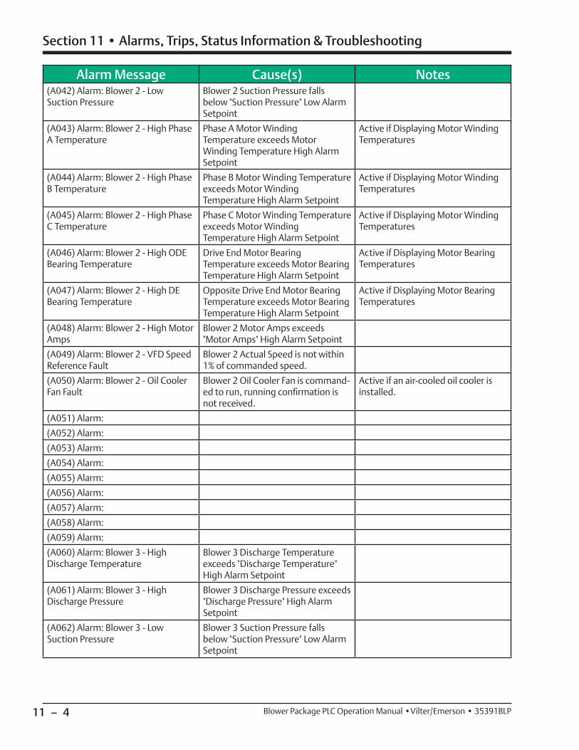
11 – 4
Section 11 • Alarms, Trips, Status Information & Troubleshooting
Blower Package PLC Operation Manual •Vilter/Emerson • 35391BLP
Alarm Message Cause(s) Notes(A042) Alarm: Blower 2 - Low Suction Pressure
Blower 2 Suction Pressure falls below "Suction Pressure" Low Alarm Setpoint
(A043) Alarm: Blower 2 - High Phase A Temperature
Phase A Motor Winding Temperature exceeds Motor Winding Temperature High Alarm Setpoint
Active if Displaying Motor Winding Temperatures
(A044) Alarm: Blower 2 - High Phase B Temperature
Phase B Motor Winding Temperature exceeds Motor Winding Temperature High Alarm Setpoint
Active if Displaying Motor Winding Temperatures
(A045) Alarm: Blower 2 - High Phase C Temperature
Phase C Motor Winding Temperature exceeds Motor Winding Temperature High Alarm Setpoint
Active if Displaying Motor Winding Temperatures
(A046) Alarm: Blower 2 - High ODE Bearing Temperature
Drive End Motor Bearing Temperature exceeds Motor Bearing Temperature High Alarm Setpoint
Active if Displaying Motor Bearing Temperatures
(A047) Alarm: Blower 2 - High DE Bearing Temperature
Opposite Drive End Motor Bearing Temperature exceeds Motor Bearing Temperature High Alarm Setpoint
Active if Displaying Motor Bearing Temperatures
(A048) Alarm: Blower 2 - High Motor Amps
Blower 2 Motor Amps exceeds "Motor Amps" High Alarm Setpoint
(A049) Alarm: Blower 2 - VFD Speed Reference Fault
Blower 2 Actual Speed is not within 1% of commanded speed.
(A050) Alarm: Blower 2 - Oil Cooler Fan Fault
Blower 2 Oil Cooler Fan is command-ed to run, running confi rmation is not received.
Active if an air-cooled oil cooler is installed.
(A051) Alarm:
(A052) Alarm:
(A053) Alarm:
(A054) Alarm:
(A055) Alarm:
(A056) Alarm:
(A057) Alarm:
(A058) Alarm:
(A059) Alarm:
(A060) Alarm: Blower 3 - High Discharge Temperature
Blower 3 Discharge Temperature exceeds "Discharge Temperature" High Alarm Setpoint
(A061) Alarm: Blower 3 - High Discharge Pressure
Blower 3 Discharge Pressure exceeds "Discharge Pressure" High Alarm Setpoint
(A062) Alarm: Blower 3 - Low Suction Pressure
Blower 3 Suction Pressure falls below "Suction Pressure" Low Alarm Setpoint

11 – 5
Section 11 • Alarms, Trips, Status Information & Troubleshooting
Blower Package PLC Operation Manual •Vilter/Emerson • 35391BLP
Alarm Message Cause(s) Notes(A063) Alarm: Blower 3 - High Phase A Temperature
Phase A Motor Winding Temperature exceeds Motor Winding Temperature High Alarm Setpoint
Active if Displaying Motor Winding Temperatures
(A064) Alarm: Blower 3 - High Phase B Temperature
Phase B Motor Winding Temperature exceeds Motor Winding Temperature High Alarm Setpoint
Active if Displaying Motor Winding Temperatures
(A065) Alarm: Blower 3 - High Phase C Temperature
Phase C Motor Winding Temperature exceeds Motor Winding Temperature High Alarm Setpoint
Active if Displaying Motor Winding Temperatures
(A066) Alarm: Blower 3 - High ODE Bearing Temperature
Drive End Motor Bearing Temperature exceeds Motor Bearing Temperature High Alarm Setpoint
Active if Displaying Motor Bearing Temperatures
(A067) Alarm: Blower 3 - High DE Bearing Temperature
Opposite Drive End Motor Bearing Temperature exceeds Motor Bearing Temperature High Alarm Setpoint
Active if Displaying Motor Bearing Temperatures
(A068) Alarm: Blower 3 - High Motor Amps
Blower 3 Motor Amps exceeds "Motor Amps" High Alarm Setpoint
(A069) Alarm: Blower 3 - VFD Speed Reference Fault
Blower 3 Actual Speed is not within 1% of commanded speed.
(A070) Alarm: Blower 3 - Oil Cooler Fan Fault
Blower 3 Oil Cooler Fan is command-ed to run, running confi rmation is not received.
Active if an air-cooled oil cooler is installed.
(A071) Alarm:
(A072) Alarm:
(A073) Alarm:
(A074) Alarm:
(A075) Alarm:
(A076) Alarm:
(A077) Alarm:
(A078) Alarm:
(A079) Alarm:
(A080) Alarm: Blower 4 - High Discharge Temperature
Blower 4 Discharge Temperature exceeds "Discharge Temperature" High Alarm Setpoint
(A081) Alarm: Blower 4 - High Discharge Pressure
Blower 4 Discharge Pressure exceeds "Discharge Pressure" High Alarm Setpoint
(A082) Alarm: Blower 4 - Low Suction Pressure
Blower 4 Suction Pressure falls below "Suction Pressure" Low Alarm Setpoint
(A083) Alarm: Blower 4 - High Phase A Temperature
Phase A Motor Winding Temperature exceeds Motor Winding Temperature High Alarm Setpoint
Active if Displaying Motor Winding Temperatures
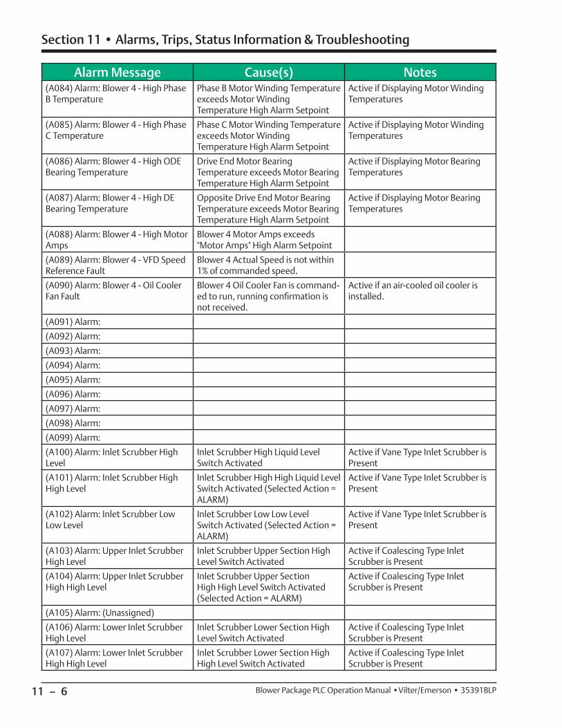
11 – 6
Section 11 • Alarms, Trips, Status Information & Troubleshooting
Blower Package PLC Operation Manual •Vilter/Emerson • 35391BLP
Alarm Message Cause(s) Notes(A084) Alarm: Blower 4 - High Phase B Temperature
Phase B Motor Winding Temperature exceeds Motor Winding Temperature High Alarm Setpoint
Active if Displaying Motor Winding Temperatures
(A085) Alarm: Blower 4 - High Phase C Temperature
Phase C Motor Winding Temperature exceeds Motor Winding Temperature High Alarm Setpoint
Active if Displaying Motor Winding Temperatures
(A086) Alarm: Blower 4 - High ODE Bearing Temperature
Drive End Motor Bearing Temperature exceeds Motor Bearing Temperature High Alarm Setpoint
Active if Displaying Motor Bearing Temperatures
(A087) Alarm: Blower 4 - High DE Bearing Temperature
Opposite Drive End Motor Bearing Temperature exceeds Motor Bearing Temperature High Alarm Setpoint
Active if Displaying Motor Bearing Temperatures
(A088) Alarm: Blower 4 - High Motor Amps
Blower 4 Motor Amps exceeds "Motor Amps" High Alarm Setpoint
(A089) Alarm: Blower 4 - VFD Speed Reference Fault
Blower 4 Actual Speed is not within 1% of commanded speed.
(A090) Alarm: Blower 4 - Oil Cooler Fan Fault
Blower 4 Oil Cooler Fan is command-ed to run, running confi rmation is not received.
Active if an air-cooled oil cooler is installed.
(A091) Alarm:
(A092) Alarm:
(A093) Alarm:
(A094) Alarm:
(A095) Alarm:
(A096) Alarm:
(A097) Alarm:
(A098) Alarm:
(A099) Alarm:
(A100) Alarm: Inlet Scrubber High Level
Inlet Scrubber High Liquid Level Switch Activated
Active if Vane Type Inlet Scrubber is Present
(A101) Alarm: Inlet Scrubber High High Level
Inlet Scrubber High High Liquid Level Switch Activated (Selected Action = ALARM)
Active if Vane Type Inlet Scrubber is Present
(A102) Alarm: Inlet Scrubber Low Low Level
Inlet Scrubber Low Low Level Switch Activated (Selected Action = ALARM)
Active if Vane Type Inlet Scrubber is Present
(A103) Alarm: Upper Inlet Scrubber High Level
Inlet Scrubber Upper Section High Level Switch Activated
Active if Coalescing Type Inlet Scrubber is Present
(A104) Alarm: Upper Inlet Scrubber High High Level
Inlet Scrubber Upper Section High High Level Switch Activated (Selected Action = ALARM)
Active if Coalescing Type Inlet Scrubber is Present
(A105) Alarm: (Unassigned)
(A106) Alarm: Lower Inlet Scrubber High Level
Inlet Scrubber Lower Section High Level Switch Activated
Active if Coalescing Type Inlet Scrubber is Present
(A107) Alarm: Lower Inlet Scrubber High High Level
Inlet Scrubber Lower Section High High Level Switch Activated
Active if Coalescing Type Inlet Scrubber is Present
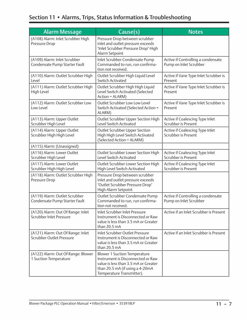
11 – 7
Section 11 • Alarms, Trips, Status Information & Troubleshooting
Blower Package PLC Operation Manual •Vilter/Emerson • 35391BLP
Alarm Message Cause(s) Notes(A108) Alarm: Inlet Scrubber High Pressure Drop
Pressure Drop between scrubber inlet and outlet pressure exceeds "Inlet Scrubber Pressure Drop" High Alarm Setpoint
(A109) Alarm: Inlet Scrubber Condensate Pump Starter Fault
Inlet Scrubber Condensate Pump Commanded to run, run confi rma-tion not received.
Active if Controlling a condensate Pump on Inlet Scrubber
(A110) Alarm: Outlet Scrubber High Level
Outlet Scrubber High Liquid Level Switch Activated
Active if Vane Type Inlet Scrubber is Present
(A111) Alarm: Outlet Scrubber High High Level
Outlet Scrubber High High Liquid Level Switch Activated (Selected Action = ALARM)
Active if Vane Type Inlet Scrubber is Present
(A112) Alarm: Outlet Scrubber Low Low Level
Outlet Scrubber Low Low Level Switch Activated (Selected Action = ALARM)
Active if Vane Type Inlet Scrubber is Present
(A113) Alarm: Upper Outlet Scrubber High Level
Outlet Scrubber Upper Section High Level Switch Activated
Active if Coalescing Type Inlet Scrubber is Present
(A114) Alarm: Upper Outlet Scrubber High High Level
Outlet Scrubber Upper Section High High Level Switch Activated (Selected Action = ALARM)
Active if Coalescing Type Inlet Scrubber is Present
(A115) Alarm: (Unassigned)
(A116) Alarm: Lower Outlet Scrubber High Level
Outlet Scrubber Lower Section High Level Switch Activated
Active if Coalescing Type Inlet Scrubber is Present
(A117) Alarm: Lower Outlet Scrubber High High Level
Outlet Scrubber Lower Section High High Level Switch Activated
Active if Coalescing Type Inlet Scrubber is Present
(A118) Alarm: Outlet Scrubber High Pressure Drop
Pressure Drop between scrubber inlet and outlet pressure exceeds "Outlet Scrubber Pressure Drop" High Alarm Setpoint
(A119) Alarm: Outlet Scrubber Condensate Pump Starter Fault
Outlet Scrubber Condensate Pump Commanded to run, run confi rma-tion not received.
Active if Controlling a condensate Pump on Inlet Scrubber
(A120) Alarm: Out Of Range: Inlet Scrubber Inlet Pressure
Inlet Scrubber Inlet Pressure Instrument is Disconnected or Raw value is less than 3.5 mA or Greater than 20.5 mA
Active if an Inlet Scrubber is Present
(A121) Alarm: Out Of Range: Inlet Scrubber Outlet Pressure
Inlet Scrubber Outlet Pressure Instrument is Disconnected or Raw value is less than 3.5 mA or Greater than 20.5 mA
Active if an Inlet Scrubber is Present
(A122) Alarm: Out Of Range: Blower 1 Suction Temperature
Blower 1 Suction Temperature Instrument is Disconnected or Raw value is less than 3.5 mA or Greater than 20.5 mA (if using a 4-20mA Temperature Transmitter).
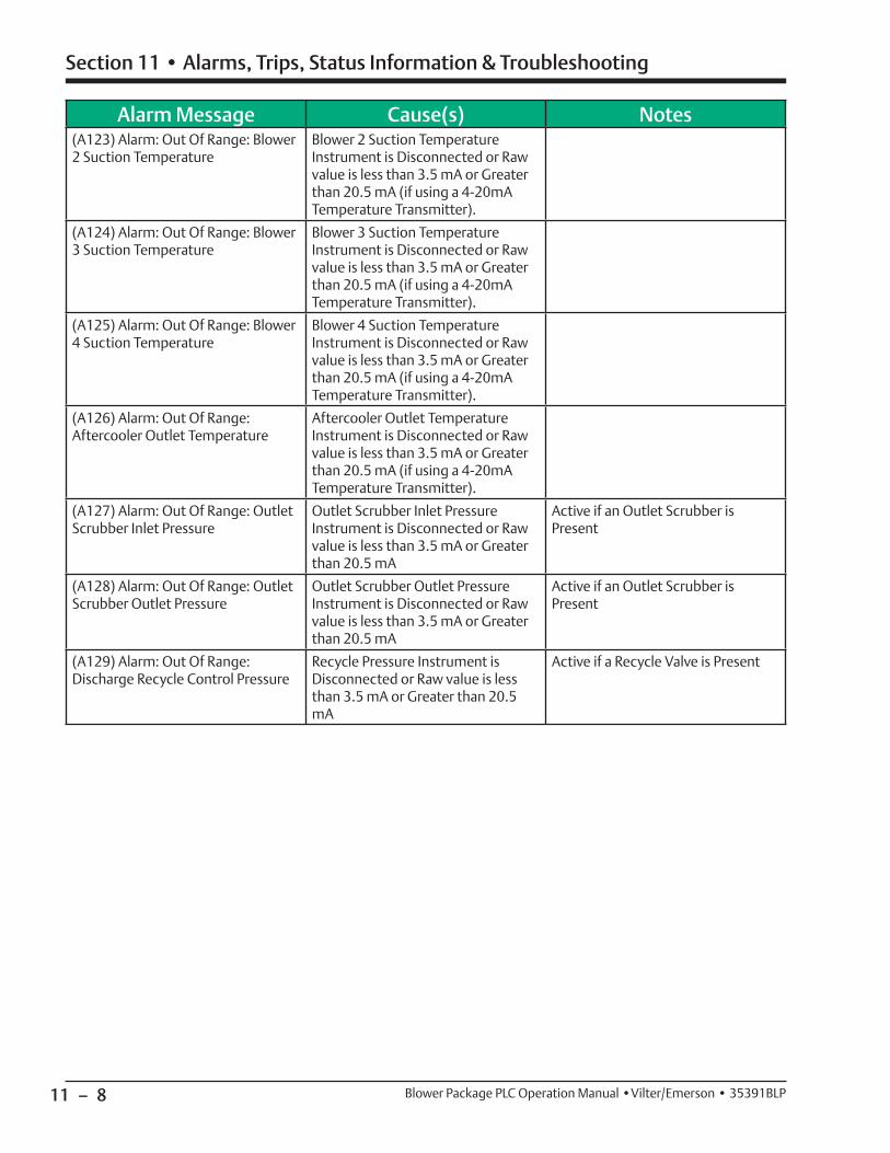
11 – 8
Section 11 • Alarms, Trips, Status Information & Troubleshooting
Blower Package PLC Operation Manual •Vilter/Emerson • 35391BLP
Alarm Message Cause(s) Notes(A123) Alarm: Out Of Range: Blower 2 Suction Temperature
Blower 2 Suction Temperature Instrument is Disconnected or Raw value is less than 3.5 mA or Greater than 20.5 mA (if using a 4-20mA Temperature Transmitter).
(A124) Alarm: Out Of Range: Blower 3 Suction Temperature
Blower 3 Suction Temperature Instrument is Disconnected or Raw value is less than 3.5 mA or Greater than 20.5 mA (if using a 4-20mA Temperature Transmitter).
(A125) Alarm: Out Of Range: Blower 4 Suction Temperature
Blower 4 Suction Temperature Instrument is Disconnected or Raw value is less than 3.5 mA or Greater than 20.5 mA (if using a 4-20mA Temperature Transmitter).
(A126) Alarm: Out Of Range: Aftercooler Outlet Temperature
Aftercooler Outlet Temperature Instrument is Disconnected or Raw value is less than 3.5 mA or Greater than 20.5 mA (if using a 4-20mA Temperature Transmitter).
(A127) Alarm: Out Of Range: Outlet Scrubber Inlet Pressure
Outlet Scrubber Inlet Pressure Instrument is Disconnected or Raw value is less than 3.5 mA or Greater than 20.5 mA
Active if an Outlet Scrubber is Present
(A128) Alarm: Out Of Range: Outlet Scrubber Outlet Pressure
Outlet Scrubber Outlet Pressure Instrument is Disconnected or Raw value is less than 3.5 mA or Greater than 20.5 mA
Active if an Outlet Scrubber is Present
(A129) Alarm: Out Of Range: Discharge Recycle Control Pressure
Recycle Pressure Instrument is Disconnected or Raw value is less than 3.5 mA or Greater than 20.5 mA
Active if a Recycle Valve is Present
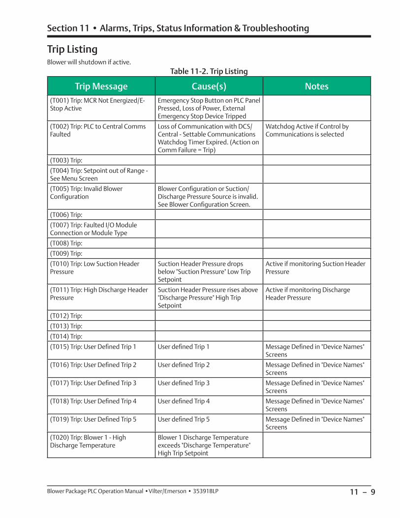
11 – 9
Section 11 • Alarms, Trips, Status Information & Troubleshooting
Blower Package PLC Operation Manual •Vilter/Emerson • 35391BLP
Trip Message Cause(s) Notes(T001) Trip: MCR Not Energized/E-Stop Active
Emergency Stop Button on PLC Panel Pressed, Loss of Power, External Emergency Stop Device Tripped
(T002) Trip: PLC to Central Comms Faulted
Loss of Communication with DCS/Central - Settable Communications Watchdog Timer Expired. (Action on Comm Failure = Trip)
Watchdog Active if Control by Communications is selected
(T003) Trip:
(T004) Trip: Setpoint out of Range - See Menu Screen
(T005) Trip: Invalid Blower Confi guration
Blower Confi guration or Suction/Discharge Pressure Source is invalid. See Blower Confi guration Screen.
(T006) Trip:
(T007) Trip: Faulted I/O Module Connection or Module Type
(T008) Trip:
(T009) Trip:
(T010) Trip: Low Suction Header Pressure
Suction Header Pressure drops below "Suction Pressure" Low Trip Setpoint
Active if monitoring Suction Header Pressure
(T011) Trip: High Discharge Header Pressure
Suction Header Pressure rises above "Discharge Pressure" High Trip Setpoint
Active if monitoring Discharge Header Pressure
(T012) Trip:
(T013) Trip:
(T014) Trip:
(T015) Trip: User Defi ned Trip 1 User defi ned Trip 1 Message Defi ned in "Device Names" Screens
(T016) Trip: User Defi ned Trip 2 User defi ned Trip 2 Message Defi ned in "Device Names" Screens
(T017) Trip: User Defi ned Trip 3 User defi ned Trip 3 Message Defi ned in "Device Names" Screens
(T018) Trip: User Defi ned Trip 4 User defi ned Trip 4 Message Defi ned in "Device Names" Screens
(T019) Trip: User Defi ned Trip 5 User defi ned Trip 5 Message Defi ned in "Device Names" Screens
(T020) Trip: Blower 1 - High Discharge Temperature
Blower 1 Discharge Temperature exceeds "Discharge Temperature" High Trip Setpoint
Trip Listing
Table 11-2. Trip ListingBlower will shutdown if active.
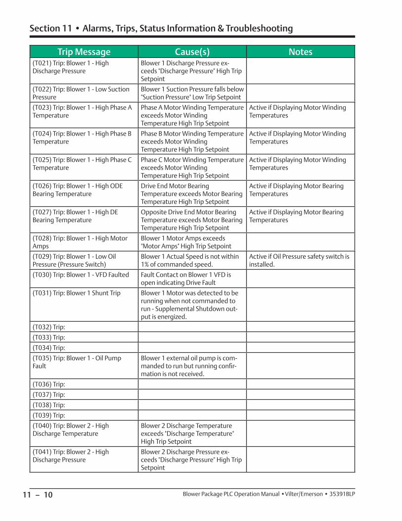
11 – 10
Section 11 • Alarms, Trips, Status Information & Troubleshooting
Blower Package PLC Operation Manual •Vilter/Emerson • 35391BLP
Trip Message Cause(s) Notes(T021) Trip: Blower 1 - High Discharge Pressure
Blower 1 Discharge Pressure ex-ceeds "Discharge Pressure" High Trip Setpoint
(T022) Trip: Blower 1 - Low Suction Pressure
Blower 1 Suction Pressure falls below "Suction Pressure" Low Trip Setpoint
(T023) Trip: Blower 1 - High Phase A Temperature
Phase A Motor Winding Temperature exceeds Motor Winding Temperature High Trip Setpoint
Active if Displaying Motor Winding Temperatures
(T024) Trip: Blower 1 - High Phase B Temperature
Phase B Motor Winding Temperature exceeds Motor Winding Temperature High Trip Setpoint
Active if Displaying Motor Winding Temperatures
(T025) Trip: Blower 1 - High Phase C Temperature
Phase C Motor Winding Temperature exceeds Motor Winding Temperature High Trip Setpoint
Active if Displaying Motor Winding Temperatures
(T026) Trip: Blower 1 - High ODE Bearing Temperature
Drive End Motor Bearing Temperature exceeds Motor Bearing Temperature High Trip Setpoint
Active if Displaying Motor Bearing Temperatures
(T027) Trip: Blower 1 - High DE Bearing Temperature
Opposite Drive End Motor Bearing Temperature exceeds Motor Bearing Temperature High Trip Setpoint
Active if Displaying Motor Bearing Temperatures
(T028) Trip: Blower 1 - High Motor Amps
Blower 1 Motor Amps exceeds "Motor Amps" High Trip Setpoint
(T029) Trip: Blower 1 - Low Oil Pressure (Pressure Switch)
Blower 1 Actual Speed is not within 1% of commanded speed.
Active if Oil Pressure safety switch is installed.
(T030) Trip: Blower 1 - VFD Faulted Fault Contact on Blower 1 VFD is open indicating Drive Fault
(T031) Trip: Blower 1 Shunt Trip Blower 1 Motor was detected to be running when not commanded to run - Supplemental Shutdown out-put is energized.
(T032) Trip:
(T033) Trip:
(T034) Trip:
(T035) Trip: Blower 1 - Oil Pump Fault
Blower 1 external oil pump is com-manded to run but running confi r-mation is not received.
(T036) Trip:
(T037) Trip:
(T038) Trip:
(T039) Trip:
(T040) Trip: Blower 2 - High Discharge Temperature
Blower 2 Discharge Temperature exceeds "Discharge Temperature" High Trip Setpoint
(T041) Trip: Blower 2 - High Discharge Pressure
Blower 2 Discharge Pressure ex-ceeds "Discharge Pressure" High Trip Setpoint
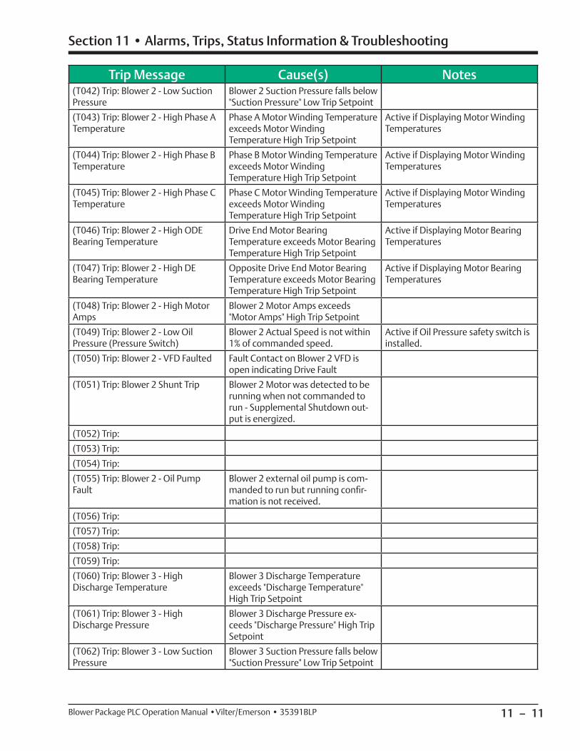
11 – 11
Section 11 • Alarms, Trips, Status Information & Troubleshooting
Blower Package PLC Operation Manual •Vilter/Emerson • 35391BLP
Trip Message Cause(s) Notes(T042) Trip: Blower 2 - Low Suction Pressure
Blower 2 Suction Pressure falls below "Suction Pressure" Low Trip Setpoint
(T043) Trip: Blower 2 - High Phase A Temperature
Phase A Motor Winding Temperature exceeds Motor Winding Temperature High Trip Setpoint
Active if Displaying Motor Winding Temperatures
(T044) Trip: Blower 2 - High Phase B Temperature
Phase B Motor Winding Temperature exceeds Motor Winding Temperature High Trip Setpoint
Active if Displaying Motor Winding Temperatures
(T045) Trip: Blower 2 - High Phase C Temperature
Phase C Motor Winding Temperature exceeds Motor Winding Temperature High Trip Setpoint
Active if Displaying Motor Winding Temperatures
(T046) Trip: Blower 2 - High ODE Bearing Temperature
Drive End Motor Bearing Temperature exceeds Motor Bearing Temperature High Trip Setpoint
Active if Displaying Motor Bearing Temperatures
(T047) Trip: Blower 2 - High DE Bearing Temperature
Opposite Drive End Motor Bearing Temperature exceeds Motor Bearing Temperature High Trip Setpoint
Active if Displaying Motor Bearing Temperatures
(T048) Trip: Blower 2 - High Motor Amps
Blower 2 Motor Amps exceeds "Motor Amps" High Trip Setpoint
(T049) Trip: Blower 2 - Low Oil Pressure (Pressure Switch)
Blower 2 Actual Speed is not within 1% of commanded speed.
Active if Oil Pressure safety switch is installed.
(T050) Trip: Blower 2 - VFD Faulted Fault Contact on Blower 2 VFD is open indicating Drive Fault
(T051) Trip: Blower 2 Shunt Trip Blower 2 Motor was detected to be running when not commanded to run - Supplemental Shutdown out-put is energized.
(T052) Trip:
(T053) Trip:
(T054) Trip:
(T055) Trip: Blower 2 - Oil Pump Fault
Blower 2 external oil pump is com-manded to run but running confi r-mation is not received.
(T056) Trip:
(T057) Trip:
(T058) Trip:
(T059) Trip:
(T060) Trip: Blower 3 - High Discharge Temperature
Blower 3 Discharge Temperature exceeds "Discharge Temperature" High Trip Setpoint
(T061) Trip: Blower 3 - High Discharge Pressure
Blower 3 Discharge Pressure ex-ceeds "Discharge Pressure" High Trip Setpoint
(T062) Trip: Blower 3 - Low Suction Pressure
Blower 3 Suction Pressure falls below "Suction Pressure" Low Trip Setpoint
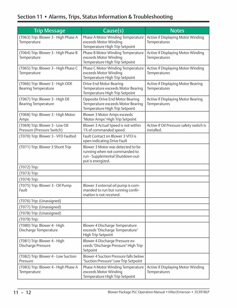
11 – 12
Section 11 • Alarms, Trips, Status Information & Troubleshooting
Blower Package PLC Operation Manual •Vilter/Emerson • 35391BLP
Trip Message Cause(s) Notes(T063) Trip: Blower 3 - High Phase A Temperature
Phase A Motor Winding Temperature exceeds Motor Winding Temperature High Trip Setpoint
Active if Displaying Motor Winding Temperatures
(T064) Trip: Blower 3 - High Phase B Temperature
Phase B Motor Winding Temperature exceeds Motor Winding Temperature High Trip Setpoint
Active if Displaying Motor Winding Temperatures
(T065) Trip: Blower 3 - High Phase C Temperature
Phase C Motor Winding Temperature exceeds Motor Winding Temperature High Trip Setpoint
Active if Displaying Motor Winding Temperatures
(T066) Trip: Blower 3 - High ODE Bearing Temperature
Drive End Motor Bearing Temperature exceeds Motor Bearing Temperature High Trip Setpoint
Active if Displaying Motor Bearing Temperatures
(T067) Trip: Blower 3 - High DE Bearing Temperature
Opposite Drive End Motor Bearing Temperature exceeds Motor Bearing Temperature High Trip Setpoint
Active if Displaying Motor Bearing Temperatures
(T068) Trip: Blower 3 - High Motor Amps
Blower 3 Motor Amps exceeds "Motor Amps" High Trip Setpoint
(T069) Trip: Blower 3 - Low Oil Pressure (Pressure Switch)
Blower 3 Actual Speed is not within 1% of commanded speed.
Active if Oil Pressure safety switch is installed.
(T070) Trip: Blower 3 - VFD Faulted Fault Contact on Blower 3 VFD is open indicating Drive Fault
(T071) Trip: Blower 3 Shunt Trip Blower 3 Motor was detected to be running when not commanded to run - Supplemental Shutdown out-put is energized.
(T072) Trip:
(T073) Trip:
(T074) Trip:
(T075) Trip: Blower 3 - Oil Pump Fault
Blower 3 external oil pump is com-manded to run but running confi r-mation is not received.
(T076) Trip: (Unassigned)
(T077) Trip: (Unassigned)
(T078) Trip: (Unassigned)
(T079) Trip:
(T080) Trip: Blower 4 - High Discharge Temperature
Blower 4 Discharge Temperature exceeds "Discharge Temperature" High Trip Setpoint
(T081) Trip: Blower 4 - High Discharge Pressure
Blower 4 Discharge Pressure ex-ceeds "Discharge Pressure" High Trip Setpoint
(T082) Trip: Blower 4 - Low Suction Pressure
Blower 4 Suction Pressure falls below "Suction Pressure" Low Trip Setpoint
(T083) Trip: Blower 4 - High Phase A Temperature
Phase A Motor Winding Temperature exceeds Motor Winding Temperature High Trip Setpoint
Active if Displaying Motor Winding Temperatures
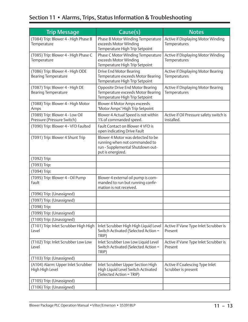
11 – 13
Section 11 • Alarms, Trips, Status Information & Troubleshooting
Blower Package PLC Operation Manual •Vilter/Emerson • 35391BLP
Trip Message Cause(s) Notes(T084) Trip: Blower 4 - High Phase B Temperature
Phase B Motor Winding Temperature exceeds Motor Winding Temperature High Trip Setpoint
Active if Displaying Motor Winding Temperatures
(T085) Trip: Blower 4 - High Phase C Temperature
Phase C Motor Winding Temperature exceeds Motor Winding Temperature High Trip Setpoint
Active if Displaying Motor Winding Temperatures
(T086) Trip: Blower 4 - High ODE Bearing Temperature
Drive End Motor Bearing Temperature exceeds Motor Bearing Temperature High Trip Setpoint
Active if Displaying Motor Bearing Temperatures
(T087) Trip: Blower 4 - High DE Bearing Temperature
Opposite Drive End Motor Bearing Temperature exceeds Motor Bearing Temperature High Trip Setpoint
Active if Displaying Motor Bearing Temperatures
(T088) Trip: Blower 4 - High Motor Amps
Blower 4 Motor Amps exceeds "Motor Amps" High Trip Setpoint
(T089) Trip: Blower 4 - Low Oil Pressure (Pressure Switch)
Blower 4 Actual Speed is not within 1% of commanded speed.
Active if Oil Pressure safety switch is installed.
(T090) Trip: Blower 4 - VFD Faulted Fault Contact on Blower 4 VFD is open indicating Drive Fault
(T091) Trip: Blower 4 Shunt Trip Blower 4 Motor was detected to be running when not commanded to run - Supplemental Shutdown out-put is energized.
(T092) Trip:
(T093) Trip:
(T094) Trip:
(T095) Trip: Blower 4 - Oil Pump Fault
Blower 4 external oil pump is com-manded to run but running confi r-mation is not received.
(T096) Trip: (Unassigned)
(T097) Trip: (Unassigned)
(T098) Trip:
(T099) Trip: (Unassigned)
(T100) Trip: (Unassigned)
(T101) Trip: Inlet Scrubber High High Level
Inlet Scrubber High High Liquid Level Switch Activated (Selected Action = TRIP)
Active if Vane Type Inlet Scrubber is Present
(T102) Trip: Inlet Scrubber Low Low Level
Inlet Scrubber Low Low Liquid Level Switch Activated (Selected Action = TRIP)
Active if Vane Type Inlet Scrubber is Present
(T103) Trip: (Unassigned)
(A104) Alarm: Upper Inlet Scrubber High High Level
Inlet Scrubber Upper Section High High Liquid Level Switch Activated (Selected Action = TRIP)
Active if Coalescing Type Inlet Scrubber is present
(T105) Trip: (Unassigned)
(T106) Trip: (Unassigned)

11 – 14
Section 11 • Alarms, Trips, Status Information & Troubleshooting
Blower Package PLC Operation Manual •Vilter/Emerson • 35391BLP
Trip Message Cause(s) Notes(T107) Alarm: Lower Inlet Scrubber High High Level
Inlet Scrubber Lower Section High High Liquid Level Switch Activated (Selected Action = TRIP)
Active if Coalescing Type Inlet Scrubber is present
(T108) Trip: (Unassigned)
(T109) Trip: (Unassigned)
(T110) Trip: (Unassigned)
(T111) Alarm: Outlet Scrubber High High Level
Outlet Scrubber High High Liquid Level Switch Activated (Selected Action = TRIP)
Active if Vane Type Outlet Scrubber is Present
(T112) Alarm: Outlet Scrubber Low Low Level
Outlet Scrubber Low Low Liquid Level Switch Activated (Selected Action = TRIP)
Active if Vane Type Outlet Scrubber is Present
(T113) Trip: (Unassigned)
(T114) Alarm: Upper Outlet Scrubber High High Level
Outlet Scrubber Upper Section High High Liquid Level Switch Activated (Selected Action = TRIP)
Active if Coalescing Type Outlet Scrubber is present
(T115) Trip: (Unassigned)
(T116) Trip: (Unassigned)
(T117) Alarm: Lower Outlet Scrubber High High Level
Outlet Scrubber Lower Section High High Liquid Level Switch Activated (Selected Action = TRIP)
Active if Coalescing Type Outlet Scrubber is present
(T118) Trip: (Unassigned)
(T119) Trip: (Unassigned)
(T120) Trip: Out Of Range: Suction Header Pressure
Pressure Instrument is Disconnected or Raw Value is less than 3.5 mA or greater than 20 mA
Active if Suction Header Pressure is Being Monitored
(T121) Trip: Out Of Range: Blower 1 Suction Pressure
Pressure Instrument is Disconnected or Raw Value is less than 3.5 mA or greater than 20 mA
(T122) Trip: Out Of Range: Blower 1 Discharge Pressure
Pressure Instrument is Disconnected or Raw Value is less than 3.5 mA or greater than 20 mA
(T123) Trip: Out Of Range: Blower 1 Discharge Temperature
RTD Input is Disconnected or Raw Value is less than 3.5 mA or greater than 20 mA (If using 4-20mA Transmitter)
(T124) Trip: Out Of Range: Blower 1 Phase A Temperature
RTD Input is Disconnected or Raw Value is less than 3.5 mA or greater than 20 mA (If using 4-20mA Transmitter)
Active if Winding Temperatures are being monitored.
(T125) Trip: Out Of Range: Blower 1 Phase B Temperature
RTD Input is Disconnected or Raw Value is less than 3.5 mA or greater than 20 mA (If using 4-20mA Transmitter)
Active if Winding Temperatures are being monitored.
(T126) Trip: Out Of Range: Blower 1 Phase C Temperature
RTD Input is Disconnected or Raw Value is less than 3.5 mA or greater than 20 mA (If using 4-20mA Transmitter)
Active if Winding Temperatures are being monitored.
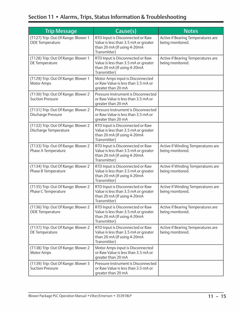
11 – 15
Section 11 • Alarms, Trips, Status Information & Troubleshooting
Blower Package PLC Operation Manual •Vilter/Emerson • 35391BLP
Trip Message Cause(s) Notes(T127) Trip: Out Of Range: Blower 1 ODE Temperature
RTD Input is Disconnected or Raw Value is less than 3.5 mA or greater than 20 mA (If using 4-20mA Transmitter)
Active if Bearing Temperatures are being monitored.
(T128) Trip: Out Of Range: Blower 1 DE Temperature
RTD Input is Disconnected or Raw Value is less than 3.5 mA or greater than 20 mA (If using 4-20mA Transmitter)
Active if Bearing Temperatures are being monitored.
(T129) Trip: Out Of Range: Blower 1 Motor Amps
Motor Amps input is Disconnected or Raw Value is less than 3.5 mA or greater than 20 mA
(T130) Trip: Out Of Range: Blower 2 Suction Pressure
Pressure Instrument is Disconnected or Raw Value is less than 3.5 mA or greater than 20 mA
(T131) Trip: Out Of Range: Blower 2 Discharge Pressure
Pressure Instrument is Disconnected or Raw Value is less than 3.5 mA or greater than 20 mA
(T132) Trip: Out Of Range: Blower 2 Discharge Temperature
RTD Input is Disconnected or Raw Value is less than 3.5 mA or greater than 20 mA (If using 4-20mA Transmitter)
(T133) Trip: Out Of Range: Blower 2 Phase A Temperature
RTD Input is Disconnected or Raw Value is less than 3.5 mA or greater than 20 mA (If using 4-20mA Transmitter)
Active if Winding Temperatures are being monitored.
(T134) Trip: Out Of Range: Blower 2 Phase B Temperature
RTD Input is Disconnected or Raw Value is less than 3.5 mA or greater than 20 mA (If using 4-20mA Transmitter)
Active if Winding Temperatures are being monitored.
(T135) Trip: Out Of Range: Blower 2 Phase C Temperature
RTD Input is Disconnected or Raw Value is less than 3.5 mA or greater than 20 mA (If using 4-20mA Transmitter)
Active if Winding Temperatures are being monitored.
(T136) Trip: Out Of Range: Blower 2 ODE Temperature
RTD Input is Disconnected or Raw Value is less than 3.5 mA or greater than 20 mA (If using 4-20mA Transmitter)
Active if Bearing Temperatures are being monitored.
(T137) Trip: Out Of Range: Blower 2 DE Temperature
RTD Input is Disconnected or Raw Value is less than 3.5 mA or greater than 20 mA (If using 4-20mA Transmitter)
Active if Bearing Temperatures are being monitored.
(T138) Trip: Out Of Range: Blower 2 Motor Amps
Motor Amps input is Disconnected or Raw Value is less than 3.5 mA or greater than 20 mA
(T139) Trip: Out Of Range: Blower 3 Suction Pressure
Pressure Instrument is Disconnected or Raw Value is less than 3.5 mA or greater than 20 mA
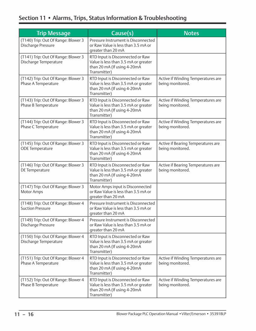
11 – 16
Section 11 • Alarms, Trips, Status Information & Troubleshooting
Blower Package PLC Operation Manual •Vilter/Emerson • 35391BLP
Trip Message Cause(s) Notes(T140) Trip: Out Of Range: Blower 3 Discharge Pressure
Pressure Instrument is Disconnected or Raw Value is less than 3.5 mA or greater than 20 mA
(T141) Trip: Out Of Range: Blower 3 Discharge Temperature
RTD Input is Disconnected or Raw Value is less than 3.5 mA or greater than 20 mA (If using 4-20mA Transmitter)
(T142) Trip: Out Of Range: Blower 3 Phase A Temperature
RTD Input is Disconnected or Raw Value is less than 3.5 mA or greater than 20 mA (If using 4-20mA Transmitter)
Active if Winding Temperatures are being monitored.
(T143) Trip: Out Of Range: Blower 3 Phase B Temperature
RTD Input is Disconnected or Raw Value is less than 3.5 mA or greater than 20 mA (If using 4-20mA Transmitter)
Active if Winding Temperatures are being monitored.
(T144) Trip: Out Of Range: Blower 3 Phase C Temperature
RTD Input is Disconnected or Raw Value is less than 3.5 mA or greater than 20 mA (If using 4-20mA Transmitter)
Active if Winding Temperatures are being monitored.
(T145) Trip: Out Of Range: Blower 3 ODE Temperature
RTD Input is Disconnected or Raw Value is less than 3.5 mA or greater than 20 mA (If using 4-20mA Transmitter)
Active if Bearing Temperatures are being monitored.
(T146) Trip: Out Of Range: Blower 3 DE Temperature
RTD Input is Disconnected or Raw Value is less than 3.5 mA or greater than 20 mA (If using 4-20mA Transmitter)
Active if Bearing Temperatures are being monitored.
(T147) Trip: Out Of Range: Blower 3 Motor Amps
Motor Amps input is Disconnected or Raw Value is less than 3.5 mA or greater than 20 mA
(T148) Trip: Out Of Range: Blower 4 Suction Pressure
Pressure Instrument is Disconnected or Raw Value is less than 3.5 mA or greater than 20 mA
(T149) Trip: Out Of Range: Blower 4 Discharge Pressure
Pressure Instrument is Disconnected or Raw Value is less than 3.5 mA or greater than 20 mA
(T150) Trip: Out Of Range: Blower 4 Discharge Temperature
RTD Input is Disconnected or Raw Value is less than 3.5 mA or greater than 20 mA (If using 4-20mA Transmitter)
(T151) Trip: Out Of Range: Blower 4 Phase A Temperature
RTD Input is Disconnected or Raw Value is less than 3.5 mA or greater than 20 mA (If using 4-20mA Transmitter)
Active if Winding Temperatures are being monitored.
(T152) Trip: Out Of Range: Blower 4 Phase B Temperature
RTD Input is Disconnected or Raw Value is less than 3.5 mA or greater than 20 mA (If using 4-20mA Transmitter)
Active if Winding Temperatures are being monitored.
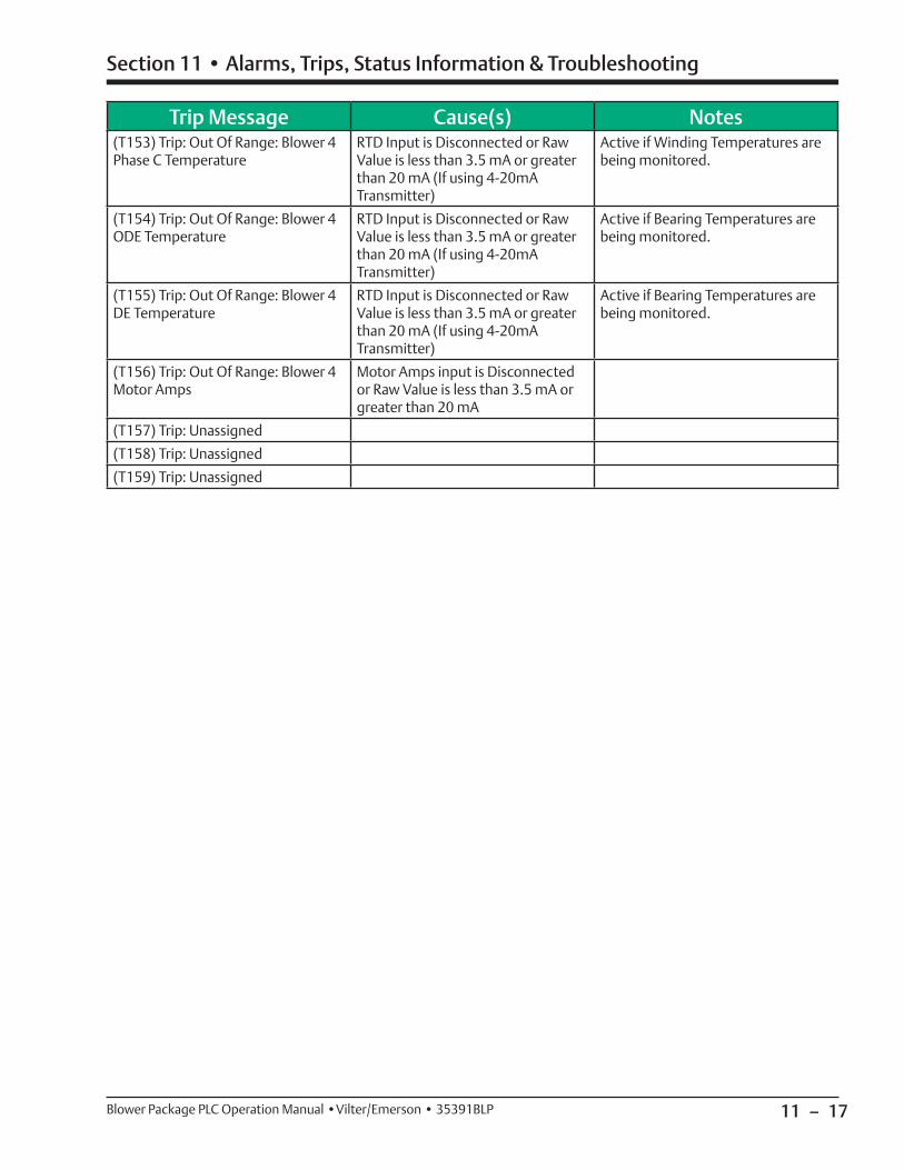
11 – 17
Section 11 • Alarms, Trips, Status Information & Troubleshooting
Blower Package PLC Operation Manual •Vilter/Emerson • 35391BLP
Trip Message Cause(s) Notes(T153) Trip: Out Of Range: Blower 4 Phase C Temperature
RTD Input is Disconnected or Raw Value is less than 3.5 mA or greater than 20 mA (If using 4-20mA Transmitter)
Active if Winding Temperatures are being monitored.
(T154) Trip: Out Of Range: Blower 4 ODE Temperature
RTD Input is Disconnected or Raw Value is less than 3.5 mA or greater than 20 mA (If using 4-20mA Transmitter)
Active if Bearing Temperatures are being monitored.
(T155) Trip: Out Of Range: Blower 4 DE Temperature
RTD Input is Disconnected or Raw Value is less than 3.5 mA or greater than 20 mA (If using 4-20mA Transmitter)
Active if Bearing Temperatures are being monitored.
(T156) Trip: Out Of Range: Blower 4 Motor Amps
Motor Amps input is Disconnected or Raw Value is less than 3.5 mA or greater than 20 mA
(T157) Trip: Unassigned
(T158) Trip: Unassigned
(T159) Trip: Unassigned
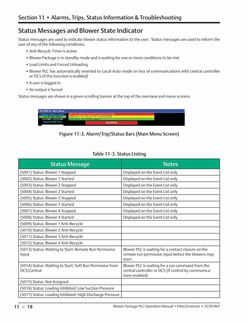
11 – 18
Section 11 • Alarms, Trips, Status Information & Troubleshooting
Blower Package PLC Operation Manual •Vilter/Emerson • 35391BLP
Status Messages and Blower State IndicatorStatus messages are used to indicate blower status information to the user. Status messages are used to inform the user of any of the following conditions.
• Anti-Recycle Timer is active
• Blower Package is in standby mode and is waiting for one or more conditions to be met
• Load Limits and Forced Unloading
• Blower PLC has automatically reverted to Local-Auto mode on loss of communications with central controller or DCS (if this function is enabled)
• A user is logged in
• An output is forced
Status messages are shown in a green scrolling banner at the top of the overview and menu screens.
Figure 11-3. Alarm/Trip/Status Bars (Main Menu Screen)
Status Message Notes(S001) Status: Blower 1 Stopped Displayed on the Event List only
(S002) Status: Blower 1 Started Displayed on the Event List only
(S003) Status: Blower 2 Stopped Displayed on the Event List only
(S004) Status: Blower 2 Started Displayed on the Event List only
(S005) Status: Blower 3 Stopped Displayed on the Event List only
(S006) Status: Blower 3 Started Displayed on the Event List only
(S007) Status: Blower 4 Stopped Displayed on the Event List only
(S008) Status: Blower 4 Started Displayed on the Event List only
(S009) Status: Blower 1 Anti-Recycle
(S010) Status: Blower 2 Anti-Recycle
(S011) Status: Blower 3 Anti-Recycle
(S012) Status: Blower 4 Anti-Recycle
(S013) Status: Waiting to Start: Remote Run Permissive Input
Blower PLC is waiting for a contact closure on the remote run permissive input before the blowers may start.
(S014) Status: Waiting to Start: Soft Run Permissive from DCS/Central
Blower PLC is waiting for a run command from the central controller or DCS (if control by communica-tions enabled)
(S015) Status: Not Assigned
(S016) Status: Loading Inhibited: Low Suction Pressure
(S017) Status: Loading Inhibited: High Discharge Pressure
Table 11-3. Status Listing
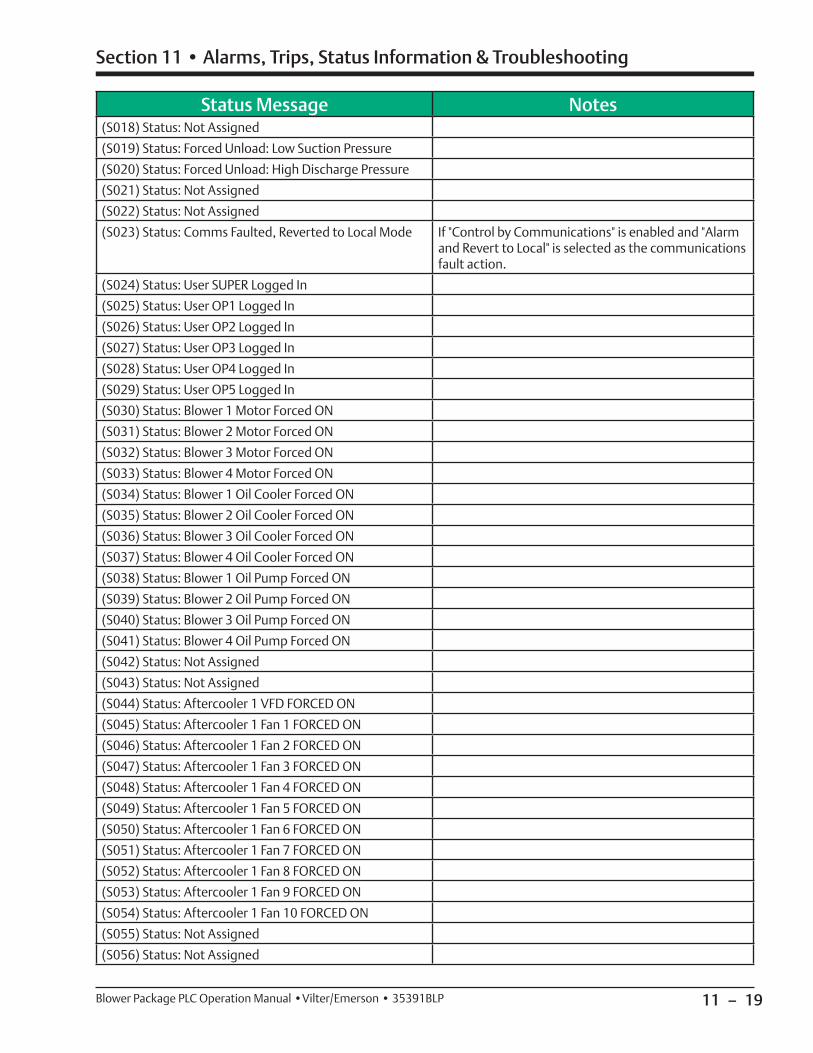
11 – 19
Section 11 • Alarms, Trips, Status Information & Troubleshooting
Blower Package PLC Operation Manual •Vilter/Emerson • 35391BLP
Status Message Notes(S018) Status: Not Assigned
(S019) Status: Forced Unload: Low Suction Pressure
(S020) Status: Forced Unload: High Discharge Pressure
(S021) Status: Not Assigned
(S022) Status: Not Assigned
(S023) Status: Comms Faulted, Reverted to Local Mode If "Control by Communications" is enabled and "Alarm and Revert to Local" is selected as the communications fault action.
(S024) Status: User SUPER Logged In
(S025) Status: User OP1 Logged In
(S026) Status: User OP2 Logged In
(S027) Status: User OP3 Logged In
(S028) Status: User OP4 Logged In
(S029) Status: User OP5 Logged In
(S030) Status: Blower 1 Motor Forced ON
(S031) Status: Blower 2 Motor Forced ON
(S032) Status: Blower 3 Motor Forced ON
(S033) Status: Blower 4 Motor Forced ON
(S034) Status: Blower 1 Oil Cooler Forced ON
(S035) Status: Blower 2 Oil Cooler Forced ON
(S036) Status: Blower 3 Oil Cooler Forced ON
(S037) Status: Blower 4 Oil Cooler Forced ON
(S038) Status: Blower 1 Oil Pump Forced ON
(S039) Status: Blower 2 Oil Pump Forced ON
(S040) Status: Blower 3 Oil Pump Forced ON
(S041) Status: Blower 4 Oil Pump Forced ON
(S042) Status: Not Assigned
(S043) Status: Not Assigned
(S044) Status: Aftercooler 1 VFD FORCED ON
(S045) Status: Aftercooler 1 Fan 1 FORCED ON
(S046) Status: Aftercooler 1 Fan 2 FORCED ON
(S047) Status: Aftercooler 1 Fan 3 FORCED ON
(S048) Status: Aftercooler 1 Fan 4 FORCED ON
(S049) Status: Aftercooler 1 Fan 5 FORCED ON
(S050) Status: Aftercooler 1 Fan 6 FORCED ON
(S051) Status: Aftercooler 1 Fan 7 FORCED ON
(S052) Status: Aftercooler 1 Fan 8 FORCED ON
(S053) Status: Aftercooler 1 Fan 9 FORCED ON
(S054) Status: Aftercooler 1 Fan 10 FORCED ON
(S055) Status: Not Assigned
(S056) Status: Not Assigned
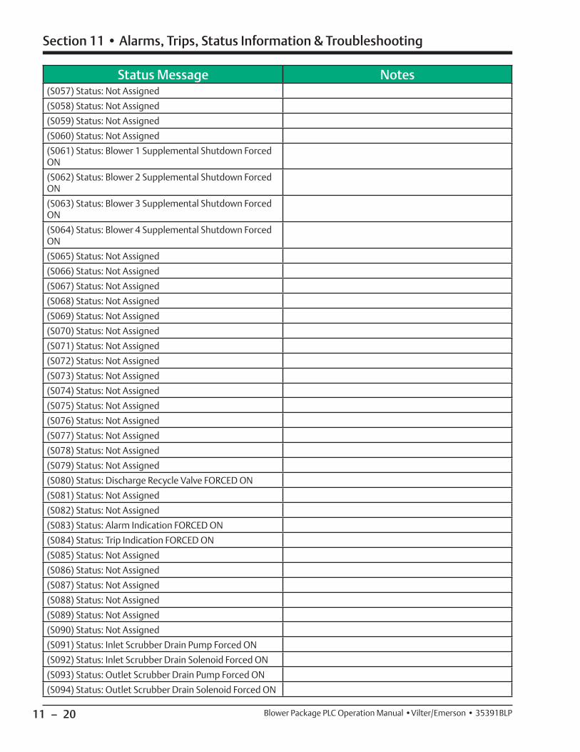
11 – 20
Section 11 • Alarms, Trips, Status Information & Troubleshooting
Blower Package PLC Operation Manual •Vilter/Emerson • 35391BLP
Status Message Notes(S057) Status: Not Assigned
(S058) Status: Not Assigned
(S059) Status: Not Assigned
(S060) Status: Not Assigned
(S061) Status: Blower 1 Supplemental Shutdown Forced ON
(S062) Status: Blower 2 Supplemental Shutdown Forced ON
(S063) Status: Blower 3 Supplemental Shutdown Forced ON
(S064) Status: Blower 4 Supplemental Shutdown Forced ON
(S065) Status: Not Assigned
(S066) Status: Not Assigned
(S067) Status: Not Assigned
(S068) Status: Not Assigned
(S069) Status: Not Assigned
(S070) Status: Not Assigned
(S071) Status: Not Assigned
(S072) Status: Not Assigned
(S073) Status: Not Assigned
(S074) Status: Not Assigned
(S075) Status: Not Assigned
(S076) Status: Not Assigned
(S077) Status: Not Assigned
(S078) Status: Not Assigned
(S079) Status: Not Assigned
(S080) Status: Discharge Recycle Valve FORCED ON
(S081) Status: Not Assigned
(S082) Status: Not Assigned
(S083) Status: Alarm Indication FORCED ON
(S084) Status: Trip Indication FORCED ON
(S085) Status: Not Assigned
(S086) Status: Not Assigned
(S087) Status: Not Assigned
(S088) Status: Not Assigned
(S089) Status: Not Assigned
(S090) Status: Not Assigned
(S091) Status: Inlet Scrubber Drain Pump Forced ON
(S092) Status: Inlet Scrubber Drain Solenoid Forced ON
(S093) Status: Outlet Scrubber Drain Pump Forced ON
(S094) Status: Outlet Scrubber Drain Solenoid Forced ON
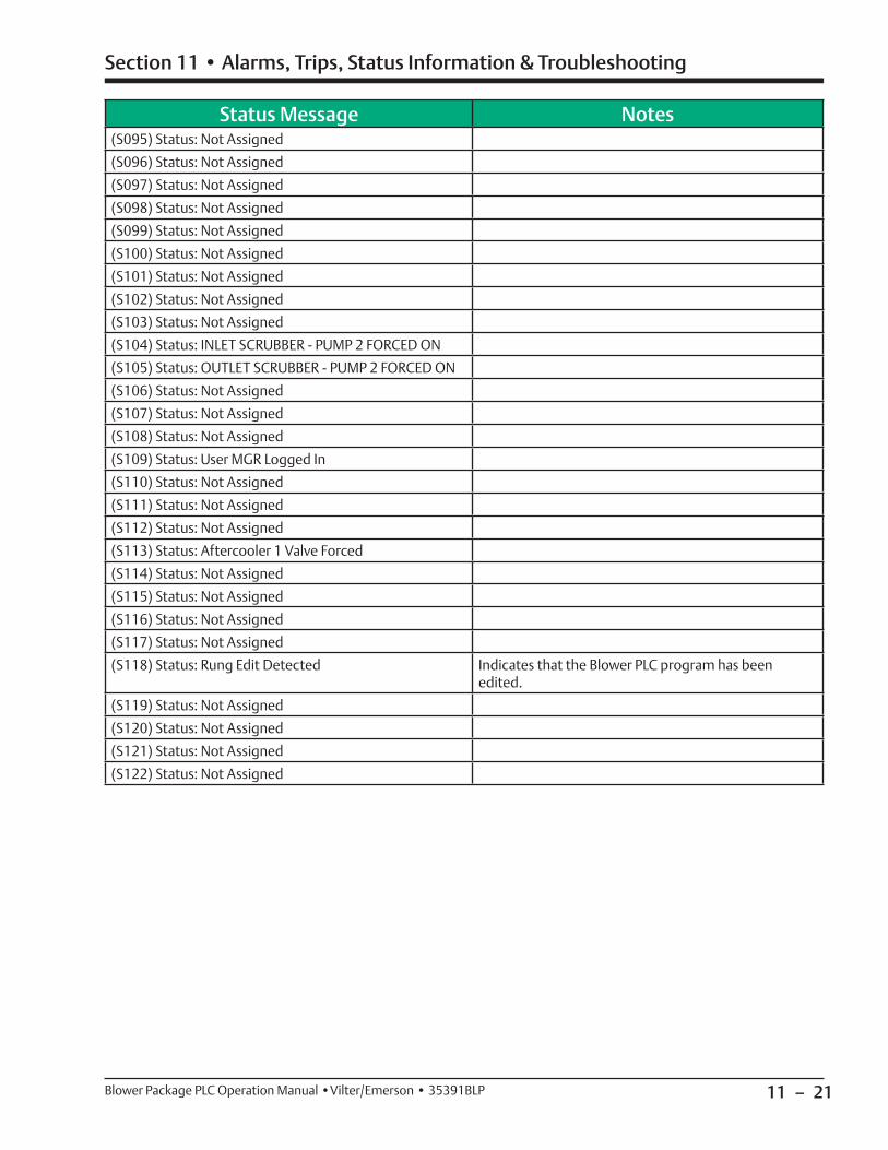
11 – 21
Section 11 • Alarms, Trips, Status Information & Troubleshooting
Blower Package PLC Operation Manual •Vilter/Emerson • 35391BLP
Status Message Notes(S095) Status: Not Assigned
(S096) Status: Not Assigned
(S097) Status: Not Assigned
(S098) Status: Not Assigned
(S099) Status: Not Assigned
(S100) Status: Not Assigned
(S101) Status: Not Assigned
(S102) Status: Not Assigned
(S103) Status: Not Assigned
(S104) Status: INLET SCRUBBER - PUMP 2 FORCED ON
(S105) Status: OUTLET SCRUBBER - PUMP 2 FORCED ON
(S106) Status: Not Assigned
(S107) Status: Not Assigned
(S108) Status: Not Assigned
(S109) Status: User MGR Logged In
(S110) Status: Not Assigned
(S111) Status: Not Assigned
(S112) Status: Not Assigned
(S113) Status: Aftercooler 1 Valve Forced
(S114) Status: Not Assigned
(S115) Status: Not Assigned
(S116) Status: Not Assigned
(S117) Status: Not Assigned
(S118) Status: Rung Edit Detected Indicates that the Blower PLC program has been edited.
(S119) Status: Not Assigned
(S120) Status: Not Assigned
(S121) Status: Not Assigned
(S122) Status: Not Assigned

11 – 22
Section 11 • Alarms, Trips, Status Information & Troubleshooting
Blower Package PLC Operation Manual •Vilter/Emerson • 35391BLP
Troubleshooting
IF THE BLOWER(S) WILL NOT START
In order to initiate a start at the blower package, make sure all permissives to initiate a start are met.
To initiate a start, the following conditions must be met:
• Control Power is ON (Emergency Stop button is not pressed and Master Control Relay is energized, indicated by pilot light on front of panel)
• No Active Trips
If a start has been initiated and the blower has not started, it is in standby mode. When in standby mode, the status banner will indicate the condition that is preventing the blower from starting.
IF CONTROL POWER WILL NOT TURN ON
If unable to turn on control power/reset an emergency stop, check the following conditions:
To energize the Master Control Relay, the following conditions must be met:
• Blower PLC Panel must be supplied with 120VAC power.
• “Master Power” Selector Switch must be ON
• Local Emergency Stop pushbutton (mounted on PLC enclosure door) must be pulled out.
• DC power supplies must be powered up and functional, “DC OK” Relay must be energized.
• CompactLogix processor must be powered up and functional, “PLC OK” Output must be ON.
• Optional/External Emergency Stop Devices are not tripped.
12 – 1
Section 12 • Communications with a Central Controller/DCS
Blower Package PLC Operation Manual •Vilter/Emerson • 35391BLP
Communication with a Central Controller/DCS
It is possible for a central controller/DCS to read live data and other information from the blower PLC as well as send commands to the blower PLC. The following sec-tion outlines the PLC addresses that are used for inter-face between the blower PLC and central controller/DCS.
VPN ACCESS
VPN access allows Vilter engineers and technicians con-nect remotely to the blower PLC for greater ease of sup-port and troubleshooting. If possible, it is recommend-ed that VPN access be provided.
To allow VPN access to a blower PLC, the following are required:
• A physical Ethernet Connection from the blower PLC to the site control network
• IP address, Subnet Mask, and Gateway address must be defi ned for each blower PLC and HMI on the site control network
• A VPN server linked to the site control network
• VPN server login information
SETTING UP COMMUNICATIONS
The blower PLC communicates using the Ethernet IP pro-tocol. Communication to other devices compatible with Ehternet IP is as simple as setting up CIP message in-structions and does not require any additional hardware other than that required for the physical connection.
Interface Data in the blower PLC is organized into arrays for simple access of data. For example, all live instru-ment data is arranged into a single block 200 elements long. To get all of the data, only one message would need to be confi gured to read an array of registers, Data type REAL, Length of 200. See the communication ta-bles below for specifi cs.
NOTE
Setting up communications using a protocol other than Ethernet IP is possible (Example Modbus RTU
or Modbus TCP), but additional hardware, software, programming, and setup are required.
WATCHDOG TIMER
A watchdog timer is used to monitor the status of the communication link between the blower PLC and Central Controller/DCS. It is only necessary to write watch-dog logic when the Central Controller/DCS is sending
commands to the blower PLC. If reading data only, the Watchdog timer is not used.
The watchdog timer works by “passing a bit” back and forth between the Blower PLC and central controller/DCS. If the blower PLC sees the bit in the same state for a settable watchdog time, the communications are faulted. The Communication fault action is selectable between “Alarm and Revert to Local Mode” or “Trip Machine.” If “Alarm and Revert to Local Mode” is se-lected, the blower will continue to run if running. If “Trip Machine” is selected, the blower will trip and shut down. The settable watchdog time and communications fault action are selected on the Confi guration Screen.
The watchdog bits that are used are:
• Blower to Central/DCS: BOOL_OUT[0].0
• Central/DCS to Blower: BOOL_IN[0].0
When the Blower PLC sees BOOL_IN[0].0 OFF it will turn BOOL_OUT[0].0 ON. To maintain the handshake, the Central Controller/DCS shall Turn BOOL_IN[0].0 ON When it sees BOOL_OUT[0].0 ON.
Data that can be Read from the Blower PLC
LIVE INSTRUMENT DATA
Tags “REAL_OUT[0]” through “REAL_OUT[99]” present the live data values as they appear on the HMI screen in the selected engineering units. The Tags “REAL_OUT[100]” through “REAL_OUT[199]” present all live data values in base units, which are PSIA for pressures and Degrees Fahrenheit for Temperatures. For data other than Pressures and Temperatures, the engineering units are fi xed and not selectable, and will appear the same in “REAL_OUT[0]” through “REAL_OUT[99]” as they will in “REAL_OUT[100]” through “REAL_OUT[199].” The en-gineering units selected are presented in the tags “INT_OUT[0]” through “INT_OUT[99].”

12 – 2
Section 12 • Communications with a Central Controller/DCS
Blower Package PLC Operation Manual •Vilter/Emerson • 35391BLP
Live Instrument Data: "REAL_OUT" (Data Type = REAL, Length = 200)Interface Tag Description Units
REAL_OUT[0] Inlet Scrubber Inlet Pressure INT_OUT[0]
REAL_OUT[1] Inlet Scrubber Outlet Pressure INT_OUT[1]
REAL_OUT[2] Inlet Scrubber Pressure Drop INT_OUT[2]
REAL_OUT[3] Outlet Scrubber Inlet Pressure INT_OUT[3]
REAL_OUT[4] Outlet Scrubber Outlet Pressure INT_OUT[4]
REAL_OUT[5] Outlet Scrubber Pressure Drop INT_OUT[5]
REAL_OUT[6] Suction Header Pressure INT_OUT[6]
REAL_OUT[7] Discharge Header Pressure INT_OUT[7]
REAL_OUT[8] Aftercooler 1 Outlet Temp INT_OUT[8]
REAL_OUT[9] Aftercooler 1 VFD Speed % Speed (100%=60Hz)
REAL_OUT[10] Discharge Recycle Control Pressure INT_OUT[10]
REAL_OUT[11] Discharge Recycle Commanded Postion % Position
REAL_OUT[12]
REAL_OUT[13]
REAL_OUT[14]
REAL_OUT[15]
REAL_OUT[16]
REAL_OUT[17]
REAL_OUT[18]
REAL_OUT[19]
Table 12-2. Live Instrument Data
Pressure Units INT_OUT[x] Value
PSIG 0
PSIA (PSID) 1
kPa[A] (kPa[D]) 2
kPa[G] 12
kg/cm^2[A] (kg/cm^2[D]) 3
kg/cm^2[G] 13
inHg (vac) PSIG (pressure)
(If positive, value is in PSIG. If negative, value is in inch-es Hg.)
4
inWC 15
Bar[A] 6
Bar[G] 16
Torr[A] 7
Torr[G] 17
Table 12-1. Engineered Units Value Interpretation (INT_OUT[x])
Temperature Units INT_OUT[x] Value
Degrees Fahrenheit 0
Degrees Celsius 1
Kelvin 2
Degrees Rankine 3
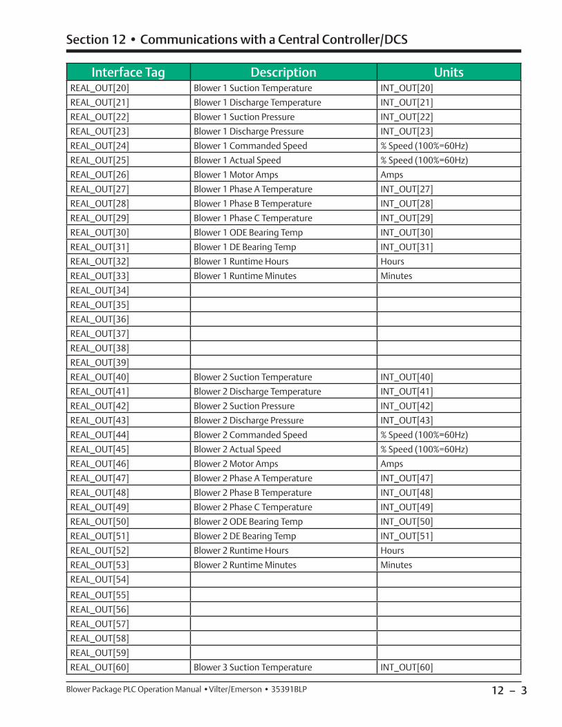
12 – 3
Section 12 • Communications with a Central Controller/DCS
Blower Package PLC Operation Manual •Vilter/Emerson • 35391BLP
Interface Tag Description UnitsREAL_OUT[20] Blower 1 Suction Temperature INT_OUT[20]
REAL_OUT[21] Blower 1 Discharge Temperature INT_OUT[21]
REAL_OUT[22] Blower 1 Suction Pressure INT_OUT[22]
REAL_OUT[23] Blower 1 Discharge Pressure INT_OUT[23]
REAL_OUT[24] Blower 1 Commanded Speed % Speed (100%=60Hz)
REAL_OUT[25] Blower 1 Actual Speed % Speed (100%=60Hz)
REAL_OUT[26] Blower 1 Motor Amps Amps
REAL_OUT[27] Blower 1 Phase A Temperature INT_OUT[27]
REAL_OUT[28] Blower 1 Phase B Temperature INT_OUT[28]
REAL_OUT[29] Blower 1 Phase C Temperature INT_OUT[29]
REAL_OUT[30] Blower 1 ODE Bearing Temp INT_OUT[30]
REAL_OUT[31] Blower 1 DE Bearing Temp INT_OUT[31]
REAL_OUT[32] Blower 1 Runtime Hours Hours
REAL_OUT[33] Blower 1 Runtime Minutes Minutes
REAL_OUT[34]
REAL_OUT[35]
REAL_OUT[36]
REAL_OUT[37]
REAL_OUT[38]
REAL_OUT[39]
REAL_OUT[40] Blower 2 Suction Temperature INT_OUT[40]
REAL_OUT[41] Blower 2 Discharge Temperature INT_OUT[41]
REAL_OUT[42] Blower 2 Suction Pressure INT_OUT[42]
REAL_OUT[43] Blower 2 Discharge Pressure INT_OUT[43]
REAL_OUT[44] Blower 2 Commanded Speed % Speed (100%=60Hz)
REAL_OUT[45] Blower 2 Actual Speed % Speed (100%=60Hz)
REAL_OUT[46] Blower 2 Motor Amps Amps
REAL_OUT[47] Blower 2 Phase A Temperature INT_OUT[47]
REAL_OUT[48] Blower 2 Phase B Temperature INT_OUT[48]
REAL_OUT[49] Blower 2 Phase C Temperature INT_OUT[49]
REAL_OUT[50] Blower 2 ODE Bearing Temp INT_OUT[50]
REAL_OUT[51] Blower 2 DE Bearing Temp INT_OUT[51]
REAL_OUT[52] Blower 2 Runtime Hours Hours
REAL_OUT[53] Blower 2 Runtime Minutes Minutes
REAL_OUT[54]
REAL_OUT[55]
REAL_OUT[56]
REAL_OUT[57]
REAL_OUT[58]
REAL_OUT[59]
REAL_OUT[60] Blower 3 Suction Temperature INT_OUT[60]

12 – 4
Section 12 • Communications with a Central Controller/DCS
Blower Package PLC Operation Manual •Vilter/Emerson • 35391BLP
Interface Tag Description UnitsREAL_OUT[61] Blower 3 Discharge Temperature INT_OUT[61]
REAL_OUT[62] Blower 3 Suction Pressure INT_OUT[62]
REAL_OUT[63] Blower 3 Discharge Pressure INT_OUT[63]
REAL_OUT[64] Blower 3 Commanded Speed % Speed (100%=60Hz)
REAL_OUT[65] Blower 3 Actual Speed % Speed (100%=60Hz)
REAL_OUT[66] Blower 3 Motor Amps Amps
REAL_OUT[67] Blower 3 Phase A Temperature INT_OUT[67]
REAL_OUT[68] Blower 3 Phase B Temperature INT_OUT[68]
REAL_OUT[69] Blower 3 Phase C Temperature INT_OUT[69]
REAL_OUT[70] Blower 3 ODE Bearing Temp INT_OUT[70]
REAL_OUT[71] Blower 3 DE Bearing Temp INT_OUT[71]
REAL_OUT[72] Blower 3 Runtime Hours Hours
REAL_OUT[73] Blower 3 Runtime Minutes Minutes
REAL_OUT[74]
REAL_OUT[75]
REAL_OUT[76]
REAL_OUT[77]
REAL_OUT[78]
REAL_OUT[79]
REAL_OUT[80] Blower 4 Suction Temperature INT_OUT[80]
REAL_OUT[81] Blower 4 Discharge Temperature INT_OUT[81]
REAL_OUT[82] Blower 4 Suction Pressure INT_OUT[82]
REAL_OUT[83] Blower 4 Discharge Pressure INT_OUT[83]
REAL_OUT[84] Blower 4 Commanded Speed % Speed (100%=60Hz)
REAL_OUT[85] Blower 4 Actual Speed % Speed (100%=60Hz)
REAL_OUT[86] Blower 4 Motor Amps Amps
REAL_OUT[87] Blower 4 Phase A Temperature INT_OUT[87]
REAL_OUT[88] Blower 4 Phase B Temperature INT_OUT[88]
REAL_OUT[89] Blower 4 Phase C Temperature INT_OUT[89]
REAL_OUT[90] Blower 4 ODE Bearing Temp INT_OUT[90]
REAL_OUT[91] Blower 4 DE Bearing Temp INT_OUT[91]
REAL_OUT[92] Blower 4 Runtime Hours Hours
REAL_OUT[93] Blower 4 Runtime Minutes Minutes
REAL_OUT[94]
REAL_OUT[95]
REAL_OUT[96]
REAL_OUT[97]
REAL_OUT[98]
REAL_OUT[99]
REAL_OUT[100] Inlet Scrubber Inlet Pressure PSIA
REAL_OUT[101] Inlet Scrubber Outlet Pressure PSIA
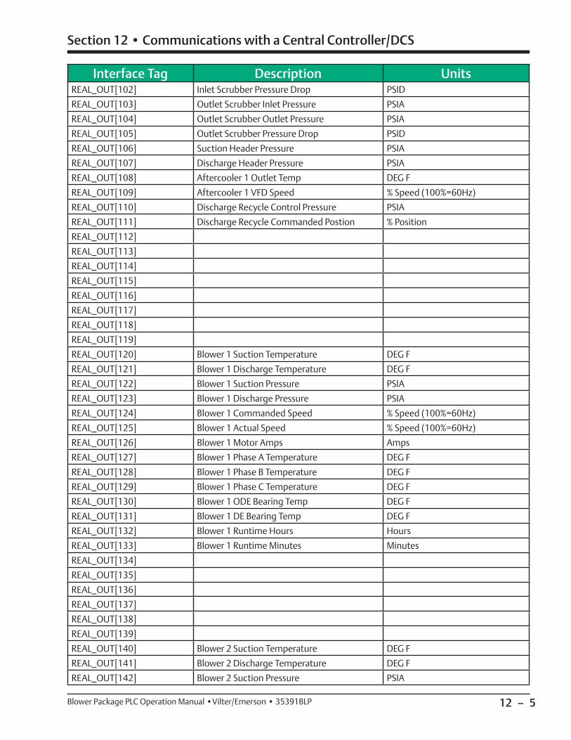
12 – 5
Section 12 • Communications with a Central Controller/DCS
Blower Package PLC Operation Manual •Vilter/Emerson • 35391BLP
Interface Tag Description UnitsREAL_OUT[102] Inlet Scrubber Pressure Drop PSID
REAL_OUT[103] Outlet Scrubber Inlet Pressure PSIA
REAL_OUT[104] Outlet Scrubber Outlet Pressure PSIA
REAL_OUT[105] Outlet Scrubber Pressure Drop PSID
REAL_OUT[106] Suction Header Pressure PSIA
REAL_OUT[107] Discharge Header Pressure PSIA
REAL_OUT[108] Aftercooler 1 Outlet Temp DEG F
REAL_OUT[109] Aftercooler 1 VFD Speed % Speed (100%=60Hz)
REAL_OUT[110] Discharge Recycle Control Pressure PSIA
REAL_OUT[111] Discharge Recycle Commanded Postion % Position
REAL_OUT[112]
REAL_OUT[113]
REAL_OUT[114]
REAL_OUT[115]
REAL_OUT[116]
REAL_OUT[117]
REAL_OUT[118]
REAL_OUT[119]
REAL_OUT[120] Blower 1 Suction Temperature DEG F
REAL_OUT[121] Blower 1 Discharge Temperature DEG F
REAL_OUT[122] Blower 1 Suction Pressure PSIA
REAL_OUT[123] Blower 1 Discharge Pressure PSIA
REAL_OUT[124] Blower 1 Commanded Speed % Speed (100%=60Hz)
REAL_OUT[125] Blower 1 Actual Speed % Speed (100%=60Hz)
REAL_OUT[126] Blower 1 Motor Amps Amps
REAL_OUT[127] Blower 1 Phase A Temperature DEG F
REAL_OUT[128] Blower 1 Phase B Temperature DEG F
REAL_OUT[129] Blower 1 Phase C Temperature DEG F
REAL_OUT[130] Blower 1 ODE Bearing Temp DEG F
REAL_OUT[131] Blower 1 DE Bearing Temp DEG F
REAL_OUT[132] Blower 1 Runtime Hours Hours
REAL_OUT[133] Blower 1 Runtime Minutes Minutes
REAL_OUT[134]
REAL_OUT[135]
REAL_OUT[136]
REAL_OUT[137]
REAL_OUT[138]
REAL_OUT[139]
REAL_OUT[140] Blower 2 Suction Temperature DEG F
REAL_OUT[141] Blower 2 Discharge Temperature DEG F
REAL_OUT[142] Blower 2 Suction Pressure PSIA
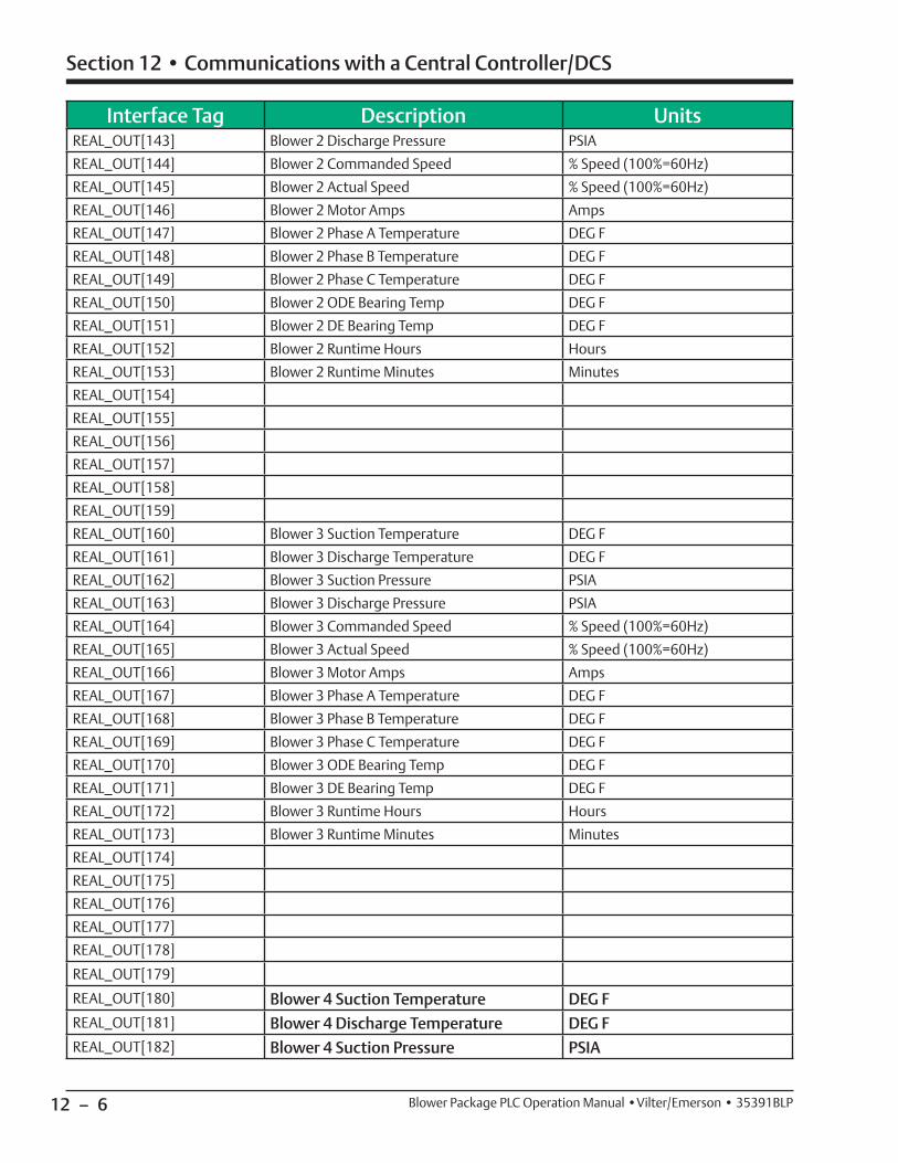
12 – 6
Section 12 • Communications with a Central Controller/DCS
Blower Package PLC Operation Manual •Vilter/Emerson • 35391BLP
Interface Tag Description UnitsREAL_OUT[143] Blower 2 Discharge Pressure PSIA
REAL_OUT[144] Blower 2 Commanded Speed % Speed (100%=60Hz)
REAL_OUT[145] Blower 2 Actual Speed % Speed (100%=60Hz)
REAL_OUT[146] Blower 2 Motor Amps Amps
REAL_OUT[147] Blower 2 Phase A Temperature DEG F
REAL_OUT[148] Blower 2 Phase B Temperature DEG F
REAL_OUT[149] Blower 2 Phase C Temperature DEG F
REAL_OUT[150] Blower 2 ODE Bearing Temp DEG F
REAL_OUT[151] Blower 2 DE Bearing Temp DEG F
REAL_OUT[152] Blower 2 Runtime Hours Hours
REAL_OUT[153] Blower 2 Runtime Minutes Minutes
REAL_OUT[154]
REAL_OUT[155]
REAL_OUT[156]
REAL_OUT[157]
REAL_OUT[158]
REAL_OUT[159]
REAL_OUT[160] Blower 3 Suction Temperature DEG F
REAL_OUT[161] Blower 3 Discharge Temperature DEG F
REAL_OUT[162] Blower 3 Suction Pressure PSIA
REAL_OUT[163] Blower 3 Discharge Pressure PSIA
REAL_OUT[164] Blower 3 Commanded Speed % Speed (100%=60Hz)
REAL_OUT[165] Blower 3 Actual Speed % Speed (100%=60Hz)
REAL_OUT[166] Blower 3 Motor Amps Amps
REAL_OUT[167] Blower 3 Phase A Temperature DEG F
REAL_OUT[168] Blower 3 Phase B Temperature DEG F
REAL_OUT[169] Blower 3 Phase C Temperature DEG F
REAL_OUT[170] Blower 3 ODE Bearing Temp DEG F
REAL_OUT[171] Blower 3 DE Bearing Temp DEG F
REAL_OUT[172] Blower 3 Runtime Hours Hours
REAL_OUT[173] Blower 3 Runtime Minutes Minutes
REAL_OUT[174]
REAL_OUT[175]
REAL_OUT[176]
REAL_OUT[177]
REAL_OUT[178] REAL_OUT[179] REAL_OUT[180] Blower 4 Suction Temperature DEG FREAL_OUT[181] Blower 4 Discharge Temperature DEG FREAL_OUT[182] Blower 4 Suction Pressure PSIA
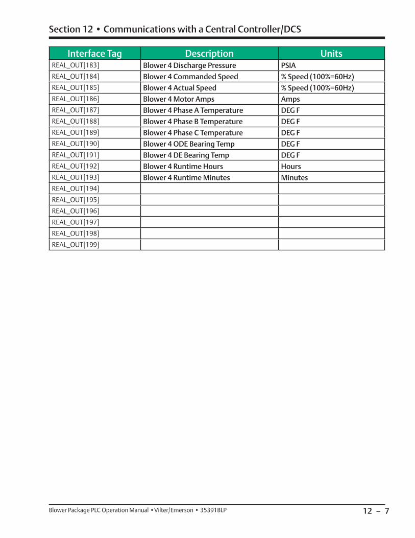
12 – 7
Section 12 • Communications with a Central Controller/DCS
Blower Package PLC Operation Manual •Vilter/Emerson • 35391BLP
Interface Tag Description UnitsREAL_OUT[183] Blower 4 Discharge Pressure PSIAREAL_OUT[184] Blower 4 Commanded Speed % Speed (100%=60Hz)REAL_OUT[185] Blower 4 Actual Speed % Speed (100%=60Hz)REAL_OUT[186] Blower 4 Motor Amps AmpsREAL_OUT[187] Blower 4 Phase A Temperature DEG FREAL_OUT[188] Blower 4 Phase B Temperature DEG FREAL_OUT[189] Blower 4 Phase C Temperature DEG FREAL_OUT[190] Blower 4 ODE Bearing Temp DEG FREAL_OUT[191] Blower 4 DE Bearing Temp DEG FREAL_OUT[192] Blower 4 Runtime Hours HoursREAL_OUT[193] Blower 4 Runtime Minutes MinutesREAL_OUT[194] REAL_OUT[195] REAL_OUT[196] REAL_OUT[197] REAL_OUT[198] REAL_OUT[199]
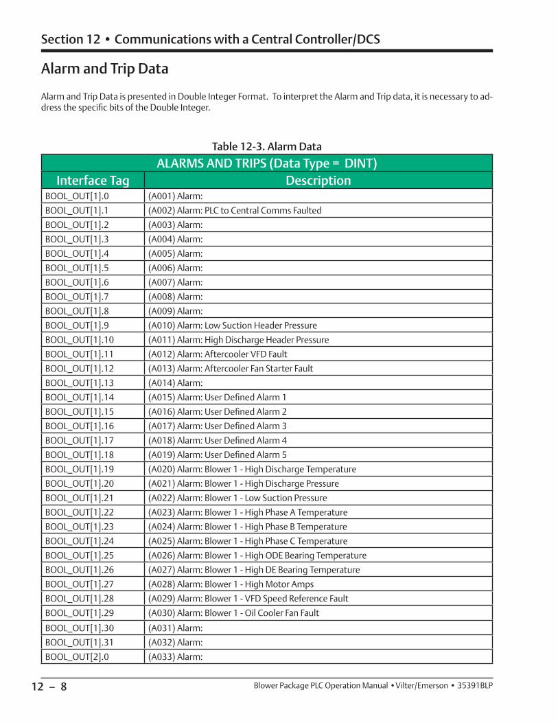
12 – 8
Section 12 • Communications with a Central Controller/DCS
Blower Package PLC Operation Manual •Vilter/Emerson • 35391BLP
Alarm and Trip Data
Alarm and Trip Data is presented in Double Integer Format. To interpret the Alarm and Trip data, it is necessary to ad-dress the specifi c bits of the Double Integer.
ALARMS AND TRIPS (Data Type = DINT)Interface Tag Description
BOOL_OUT[1].0 (A001) Alarm:
BOOL_OUT[1].1 (A002) Alarm: PLC to Central Comms Faulted
BOOL_OUT[1].2 (A003) Alarm:
BOOL_OUT[1].3 (A004) Alarm:
BOOL_OUT[1].4 (A005) Alarm:
BOOL_OUT[1].5 (A006) Alarm:
BOOL_OUT[1].6 (A007) Alarm:
BOOL_OUT[1].7 (A008) Alarm:
BOOL_OUT[1].8 (A009) Alarm:
BOOL_OUT[1].9 (A010) Alarm: Low Suction Header Pressure
BOOL_OUT[1].10 (A011) Alarm: High Discharge Header Pressure
BOOL_OUT[1].11 (A012) Alarm: Aftercooler VFD Fault
BOOL_OUT[1].12 (A013) Alarm: Aftercooler Fan Starter Fault
BOOL_OUT[1].13 (A014) Alarm:
BOOL_OUT[1].14 (A015) Alarm: User Defi ned Alarm 1
BOOL_OUT[1].15 (A016) Alarm: User Defi ned Alarm 2
BOOL_OUT[1].16 (A017) Alarm: User Defi ned Alarm 3
BOOL_OUT[1].17 (A018) Alarm: User Defi ned Alarm 4
BOOL_OUT[1].18 (A019) Alarm: User Defi ned Alarm 5
BOOL_OUT[1].19 (A020) Alarm: Blower 1 - High Discharge Temperature
BOOL_OUT[1].20 (A021) Alarm: Blower 1 - High Discharge Pressure
BOOL_OUT[1].21 (A022) Alarm: Blower 1 - Low Suction Pressure
BOOL_OUT[1].22 (A023) Alarm: Blower 1 - High Phase A Temperature
BOOL_OUT[1].23 (A024) Alarm: Blower 1 - High Phase B Temperature
BOOL_OUT[1].24 (A025) Alarm: Blower 1 - High Phase C Temperature
BOOL_OUT[1].25 (A026) Alarm: Blower 1 - High ODE Bearing Temperature
BOOL_OUT[1].26 (A027) Alarm: Blower 1 - High DE Bearing Temperature
BOOL_OUT[1].27 (A028) Alarm: Blower 1 - High Motor Amps
BOOL_OUT[1].28 (A029) Alarm: Blower 1 - VFD Speed Reference Fault
BOOL_OUT[1].29 (A030) Alarm: Blower 1 - Oil Cooler Fan Fault
BOOL_OUT[1].30 (A031) Alarm:
BOOL_OUT[1].31 (A032) Alarm:
BOOL_OUT[2].0 (A033) Alarm:
Table 12-3. Alarm Data
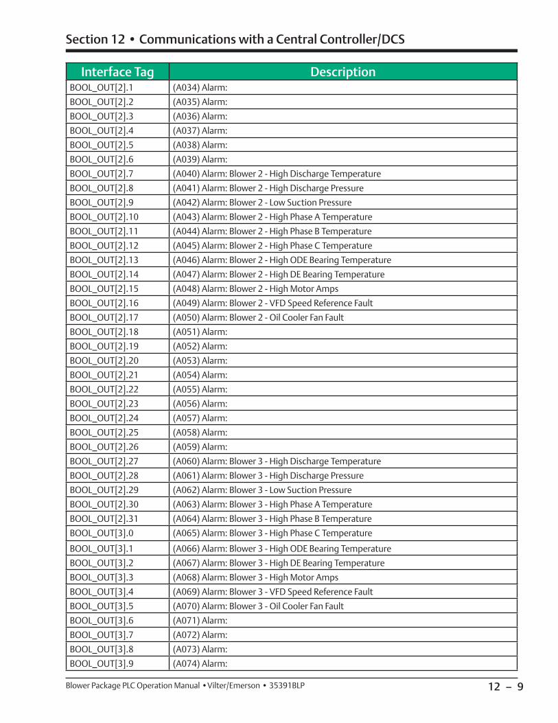
12 – 9
Section 12 • Communications with a Central Controller/DCS
Blower Package PLC Operation Manual •Vilter/Emerson • 35391BLP
Interface Tag DescriptionBOOL_OUT[2].1 (A034) Alarm:
BOOL_OUT[2].2 (A035) Alarm:
BOOL_OUT[2].3 (A036) Alarm:
BOOL_OUT[2].4 (A037) Alarm:
BOOL_OUT[2].5 (A038) Alarm:
BOOL_OUT[2].6 (A039) Alarm:
BOOL_OUT[2].7 (A040) Alarm: Blower 2 - High Discharge Temperature
BOOL_OUT[2].8 (A041) Alarm: Blower 2 - High Discharge Pressure
BOOL_OUT[2].9 (A042) Alarm: Blower 2 - Low Suction Pressure
BOOL_OUT[2].10 (A043) Alarm: Blower 2 - High Phase A Temperature
BOOL_OUT[2].11 (A044) Alarm: Blower 2 - High Phase B Temperature
BOOL_OUT[2].12 (A045) Alarm: Blower 2 - High Phase C Temperature
BOOL_OUT[2].13 (A046) Alarm: Blower 2 - High ODE Bearing Temperature
BOOL_OUT[2].14 (A047) Alarm: Blower 2 - High DE Bearing Temperature
BOOL_OUT[2].15 (A048) Alarm: Blower 2 - High Motor Amps
BOOL_OUT[2].16 (A049) Alarm: Blower 2 - VFD Speed Reference Fault
BOOL_OUT[2].17 (A050) Alarm: Blower 2 - Oil Cooler Fan Fault
BOOL_OUT[2].18 (A051) Alarm:
BOOL_OUT[2].19 (A052) Alarm:
BOOL_OUT[2].20 (A053) Alarm:
BOOL_OUT[2].21 (A054) Alarm:
BOOL_OUT[2].22 (A055) Alarm:
BOOL_OUT[2].23 (A056) Alarm:
BOOL_OUT[2].24 (A057) Alarm:
BOOL_OUT[2].25 (A058) Alarm:
BOOL_OUT[2].26 (A059) Alarm:
BOOL_OUT[2].27 (A060) Alarm: Blower 3 - High Discharge Temperature
BOOL_OUT[2].28 (A061) Alarm: Blower 3 - High Discharge Pressure
BOOL_OUT[2].29 (A062) Alarm: Blower 3 - Low Suction Pressure
BOOL_OUT[2].30 (A063) Alarm: Blower 3 - High Phase A Temperature
BOOL_OUT[2].31 (A064) Alarm: Blower 3 - High Phase B Temperature
BOOL_OUT[3].0 (A065) Alarm: Blower 3 - High Phase C Temperature
BOOL_OUT[3].1 (A066) Alarm: Blower 3 - High ODE Bearing Temperature
BOOL_OUT[3].2 (A067) Alarm: Blower 3 - High DE Bearing Temperature
BOOL_OUT[3].3 (A068) Alarm: Blower 3 - High Motor Amps
BOOL_OUT[3].4 (A069) Alarm: Blower 3 - VFD Speed Reference Fault
BOOL_OUT[3].5 (A070) Alarm: Blower 3 - Oil Cooler Fan Fault
BOOL_OUT[3].6 (A071) Alarm:
BOOL_OUT[3].7 (A072) Alarm:
BOOL_OUT[3].8 (A073) Alarm:
BOOL_OUT[3].9 (A074) Alarm:

12 – 10
Section 12 • Communications with a Central Controller/DCS
Blower Package PLC Operation Manual •Vilter/Emerson • 35391BLP
Interface Tag DescriptionBOOL_OUT[3].10 (A075) Alarm:
BOOL_OUT[3].11 (A076) Alarm:
BOOL_OUT[3].12 (A077) Alarm:
BOOL_OUT[3].13 (A078) Alarm:
BOOL_OUT[3].14 (A079) Alarm:
BOOL_OUT[3].15 (A080) Alarm: Blower 4 - High Discharge Temperature
BOOL_OUT[3].16 (A081) Alarm: Blower 4 - High Discharge Pressure
BOOL_OUT[3].17 (A082) Alarm: Blower 4 - Low Suction Pressure
BOOL_OUT[3].18 (A083) Alarm: Blower 4 - High Phase A Temperature
BOOL_OUT[3].19 (A084) Alarm: Blower 4 - High Phase B Temperature
BOOL_OUT[3].20 (A085) Alarm: Blower 4 - High Phase C Temperature
BOOL_OUT[3].21 (A086) Alarm: Blower 4 - High ODE Bearing Temperature
BOOL_OUT[3].22 (A087) Alarm: Blower 4 - High DE Bearing Temperature
BOOL_OUT[3].23 (A088) Alarm: Blower 4 - High Motor Amps
BOOL_OUT[3].24 (A089) Alarm: Blower 4 - VFD Speed Reference Fault
BOOL_OUT[3].25 (A090) Alarm: Blower 4 - Oil Cooler Fan Fault
BOOL_OUT[3].26 (A091) Alarm:
BOOL_OUT[3].27 (A092) Alarm:
BOOL_OUT[3].28 (A093) Alarm:
BOOL_OUT[3].29 (A094) Alarm:
BOOL_OUT[3].30 (A095) Alarm:
BOOL_OUT[3].31 (A096) Alarm:
BOOL_OUT[4].0 (A097) Alarm:
BOOL_OUT[4].1 (A098) Alarm:
BOOL_OUT[4].2 (A099) Alarm:
BOOL_OUT[4].3 (A100) Alarm: Inlet Scrubber High Level
BOOL_OUT[4].4 (A101) Alarm: Inlet Scrubber High High Level
BOOL_OUT[4].5 (A102) Alarm: Inlet Scrubber Low Low Level
BOOL_OUT[4].6 (A103) Alarm: Upper Inlet Scrubber High Level
BOOL_OUT[4].7 (A104) Alarm: Upper Inlet Scrubber High High Level
BOOL_OUT[4].8 (A105) Alarm: (Unassigned)
BOOL_OUT[4].9 (A106) Alarm: Lower Inlet Scrubber High Level
BOOL_OUT[4].10 (A107) Alarm: Lower Inlet Scrubber High High Level
BOOL_OUT[4].11 (A108) Alarm: Inlet Scrubber High Pressure Drop
BOOL_OUT[4].12 (A109) Alarm: Inlet Scrubber Condensate Pump Starter Fault
BOOL_OUT[4].13 (A110) Alarm: Outlet Scrubber High Level
BOOL_OUT[4].14 (A111) Alarm: Outlet Scrubber High High Level
BOOL_OUT[4].15 (A112) Alarm: Outlet Scrubber Low Low Level
BOOL_OUT[4].16 (A113) Alarm: Upper Outlet Scrubber High Level
BOOL_OUT[4].17 (A114) Alarm: Upper Outlet Scrubber High High Level
BOOL_OUT[4].18 (A115) Alarm: (Unassigned)
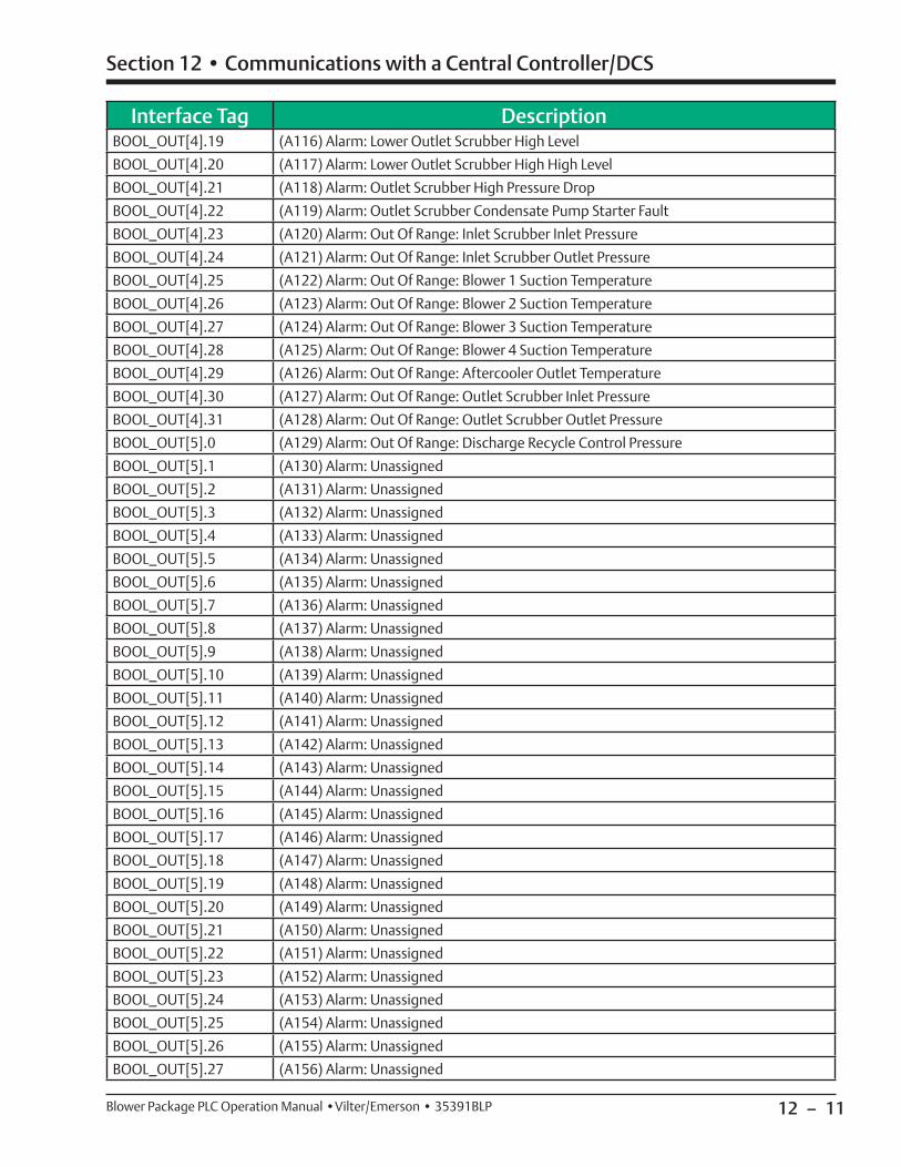
12 – 11
Section 12 • Communications with a Central Controller/DCS
Blower Package PLC Operation Manual •Vilter/Emerson • 35391BLP
Interface Tag DescriptionBOOL_OUT[4].19 (A116) Alarm: Lower Outlet Scrubber High Level
BOOL_OUT[4].20 (A117) Alarm: Lower Outlet Scrubber High High Level
BOOL_OUT[4].21 (A118) Alarm: Outlet Scrubber High Pressure Drop
BOOL_OUT[4].22 (A119) Alarm: Outlet Scrubber Condensate Pump Starter Fault
BOOL_OUT[4].23 (A120) Alarm: Out Of Range: Inlet Scrubber Inlet Pressure
BOOL_OUT[4].24 (A121) Alarm: Out Of Range: Inlet Scrubber Outlet Pressure
BOOL_OUT[4].25 (A122) Alarm: Out Of Range: Blower 1 Suction Temperature
BOOL_OUT[4].26 (A123) Alarm: Out Of Range: Blower 2 Suction Temperature
BOOL_OUT[4].27 (A124) Alarm: Out Of Range: Blower 3 Suction Temperature
BOOL_OUT[4].28 (A125) Alarm: Out Of Range: Blower 4 Suction Temperature
BOOL_OUT[4].29 (A126) Alarm: Out Of Range: Aftercooler Outlet Temperature
BOOL_OUT[4].30 (A127) Alarm: Out Of Range: Outlet Scrubber Inlet Pressure
BOOL_OUT[4].31 (A128) Alarm: Out Of Range: Outlet Scrubber Outlet Pressure
BOOL_OUT[5].0 (A129) Alarm: Out Of Range: Discharge Recycle Control Pressure
BOOL_OUT[5].1 (A130) Alarm: Unassigned
BOOL_OUT[5].2 (A131) Alarm: Unassigned
BOOL_OUT[5].3 (A132) Alarm: Unassigned
BOOL_OUT[5].4 (A133) Alarm: Unassigned
BOOL_OUT[5].5 (A134) Alarm: Unassigned
BOOL_OUT[5].6 (A135) Alarm: Unassigned
BOOL_OUT[5].7 (A136) Alarm: Unassigned
BOOL_OUT[5].8 (A137) Alarm: Unassigned
BOOL_OUT[5].9 (A138) Alarm: Unassigned
BOOL_OUT[5].10 (A139) Alarm: Unassigned
BOOL_OUT[5].11 (A140) Alarm: Unassigned
BOOL_OUT[5].12 (A141) Alarm: Unassigned
BOOL_OUT[5].13 (A142) Alarm: Unassigned
BOOL_OUT[5].14 (A143) Alarm: Unassigned
BOOL_OUT[5].15 (A144) Alarm: Unassigned
BOOL_OUT[5].16 (A145) Alarm: Unassigned
BOOL_OUT[5].17 (A146) Alarm: Unassigned
BOOL_OUT[5].18 (A147) Alarm: Unassigned
BOOL_OUT[5].19 (A148) Alarm: Unassigned
BOOL_OUT[5].20 (A149) Alarm: Unassigned
BOOL_OUT[5].21 (A150) Alarm: Unassigned
BOOL_OUT[5].22 (A151) Alarm: Unassigned
BOOL_OUT[5].23 (A152) Alarm: Unassigned
BOOL_OUT[5].24 (A153) Alarm: Unassigned
BOOL_OUT[5].25 (A154) Alarm: Unassigned
BOOL_OUT[5].26 (A155) Alarm: Unassigned
BOOL_OUT[5].27 (A156) Alarm: Unassigned
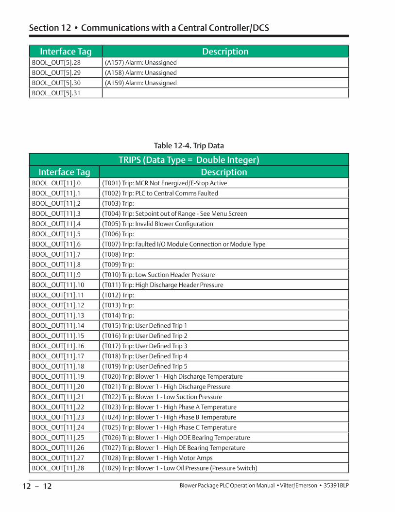
12 – 12
Section 12 • Communications with a Central Controller/DCS
Blower Package PLC Operation Manual •Vilter/Emerson • 35391BLP
Interface Tag DescriptionBOOL_OUT[5].28 (A157) Alarm: Unassigned
BOOL_OUT[5].29 (A158) Alarm: Unassigned
BOOL_OUT[5].30 (A159) Alarm: Unassigned
BOOL_OUT[5].31
TRIPS (Data Type = Double Integer)Interface Tag Description
BOOL_OUT[11].0 (T001) Trip: MCR Not Energized/E-Stop Active
BOOL_OUT[11].1 (T002) Trip: PLC to Central Comms Faulted
BOOL_OUT[11].2 (T003) Trip:
BOOL_OUT[11].3 (T004) Trip: Setpoint out of Range - See Menu Screen
BOOL_OUT[11].4 (T005) Trip: Invalid Blower Confi guration
BOOL_OUT[11].5 (T006) Trip:
BOOL_OUT[11].6 (T007) Trip: Faulted I/O Module Connection or Module Type
BOOL_OUT[11].7 (T008) Trip:
BOOL_OUT[11].8 (T009) Trip:
BOOL_OUT[11].9 (T010) Trip: Low Suction Header Pressure
BOOL_OUT[11].10 (T011) Trip: High Discharge Header Pressure
BOOL_OUT[11].11 (T012) Trip:
BOOL_OUT[11].12 (T013) Trip:
BOOL_OUT[11].13 (T014) Trip:
BOOL_OUT[11].14 (T015) Trip: User Defi ned Trip 1
BOOL_OUT[11].15 (T016) Trip: User Defi ned Trip 2
BOOL_OUT[11].16 (T017) Trip: User Defi ned Trip 3
BOOL_OUT[11].17 (T018) Trip: User Defi ned Trip 4
BOOL_OUT[11].18 (T019) Trip: User Defi ned Trip 5
BOOL_OUT[11].19 (T020) Trip: Blower 1 - High Discharge Temperature
BOOL_OUT[11].20 (T021) Trip: Blower 1 - High Discharge Pressure
BOOL_OUT[11].21 (T022) Trip: Blower 1 - Low Suction Pressure
BOOL_OUT[11].22 (T023) Trip: Blower 1 - High Phase A Temperature
BOOL_OUT[11].23 (T024) Trip: Blower 1 - High Phase B Temperature
BOOL_OUT[11].24 (T025) Trip: Blower 1 - High Phase C Temperature
BOOL_OUT[11].25 (T026) Trip: Blower 1 - High ODE Bearing Temperature
BOOL_OUT[11].26 (T027) Trip: Blower 1 - High DE Bearing Temperature
BOOL_OUT[11].27 (T028) Trip: Blower 1 - High Motor Amps
BOOL_OUT[11].28 (T029) Trip: Blower 1 - Low Oil Pressure (Pressure Switch)
Table 12-4. Trip Data
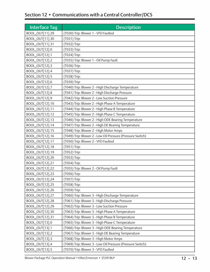
12 – 13
Section 12 • Communications with a Central Controller/DCS
Blower Package PLC Operation Manual •Vilter/Emerson • 35391BLP
Interface Tag DescriptionBOOL_OUT[11].29 (T030) Trip: Blower 1 - VFD Faulted
BOOL_OUT[11].30 (T031) Trip:
BOOL_OUT[11].31 (T032) Trip:
BOOL_OUT[12].0 (T033) Trip:
BOOL_OUT[12].1 (T034) Trip:
BOOL_OUT[12].2 (T035) Trip: Blower 1 - Oil Pump Fault
BOOL_OUT[12].3 (T036) Trip:
BOOL_OUT[12].4 (T037) Trip:
BOOL_OUT[12].5 (T038) Trip:
BOOL_OUT[12].6 (T039) Trip:
BOOL_OUT[12].7 (T040) Trip: Blower 2 - High Discharge Temperature
BOOL_OUT[12].8 (T041) Trip: Blower 2 - High Discharge Pressure
BOOL_OUT[12].9 (T042) Trip: Blower 2 - Low Suction Pressure
BOOL_OUT[12].10 (T043) Trip: Blower 2 - High Phase A Temperature
BOOL_OUT[12].11 (T044) Trip: Blower 2 - High Phase B Temperature
BOOL_OUT[12].12 (T045) Trip: Blower 2 - High Phase C Temperature
BOOL_OUT[12].13 (T046) Trip: Blower 2 - High ODE Bearing Temperature
BOOL_OUT[12].14 (T047) Trip: Blower 2 - High DE Bearing Temperature
BOOL_OUT[12].15 (T048) Trip: Blower 2 - High Motor Amps
BOOL_OUT[12].16 (T049) Trip: Blower 2 - Low Oil Pressure (Pressure Switch)
BOOL_OUT[12].17 (T050) Trip: Blower 2 - VFD Faulted
BOOL_OUT[12].18 (T051) Trip:
BOOL_OUT[12].19 (T052) Trip:
BOOL_OUT[12].20 (T053) Trip:
BOOL_OUT[12].21 (T054) Trip:
BOOL_OUT[12].22 (T055) Trip: Blower 2 - Oil Pump Fault
BOOL_OUT[12].23 (T056) Trip:
BOOL_OUT[12].24 (T057) Trip:
BOOL_OUT[12].25 (T058) Trip:
BOOL_OUT[12].26 (T059) Trip:
BOOL_OUT[12].27 (T060) Trip: Blower 3 - High Discharge Temperature
BOOL_OUT[12].28 (T061) Trip: Blower 3 - High Discharge Pressure
BOOL_OUT[12].29 (T062) Trip: Blower 3 - Low Suction Pressure
BOOL_OUT[12].30 (T063) Trip: Blower 3 - High Phase A Temperature
BOOL_OUT[12].31 (T064) Trip: Blower 3 - High Phase B Temperature
BOOL_OUT[13].0 (T065) Trip: Blower 3 - High Phase C Temperature
BOOL_OUT[13].1 (T066) Trip: Blower 3 - High ODE Bearing Temperature
BOOL_OUT[13].2 (T067) Trip: Blower 3 - High DE Bearing Temperature
BOOL_OUT[13].3 (T068) Trip: Blower 3 - High Motor Amps
BOOL_OUT[13].4 (T069) Trip: Blower 3 - Low Oil Pressure (Pressure Switch)
BOOL_OUT[13].5 (T070) Trip: Blower 3 - VFD Faulted
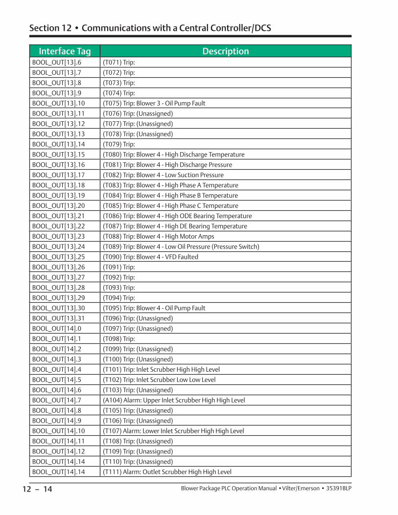
12 – 14
Section 12 • Communications with a Central Controller/DCS
Blower Package PLC Operation Manual •Vilter/Emerson • 35391BLP
Interface Tag DescriptionBOOL_OUT[13].6 (T071) Trip:
BOOL_OUT[13].7 (T072) Trip:
BOOL_OUT[13].8 (T073) Trip:
BOOL_OUT[13].9 (T074) Trip:
BOOL_OUT[13].10 (T075) Trip: Blower 3 - Oil Pump Fault
BOOL_OUT[13].11 (T076) Trip: (Unassigned)
BOOL_OUT[13].12 (T077) Trip: (Unassigned)
BOOL_OUT[13].13 (T078) Trip: (Unassigned)
BOOL_OUT[13].14 (T079) Trip:
BOOL_OUT[13].15 (T080) Trip: Blower 4 - High Discharge Temperature
BOOL_OUT[13].16 (T081) Trip: Blower 4 - High Discharge Pressure
BOOL_OUT[13].17 (T082) Trip: Blower 4 - Low Suction Pressure
BOOL_OUT[13].18 (T083) Trip: Blower 4 - High Phase A Temperature
BOOL_OUT[13].19 (T084) Trip: Blower 4 - High Phase B Temperature
BOOL_OUT[13].20 (T085) Trip: Blower 4 - High Phase C Temperature
BOOL_OUT[13].21 (T086) Trip: Blower 4 - High ODE Bearing Temperature
BOOL_OUT[13].22 (T087) Trip: Blower 4 - High DE Bearing Temperature
BOOL_OUT[13].23 (T088) Trip: Blower 4 - High Motor Amps
BOOL_OUT[13].24 (T089) Trip: Blower 4 - Low Oil Pressure (Pressure Switch)
BOOL_OUT[13].25 (T090) Trip: Blower 4 - VFD Faulted
BOOL_OUT[13].26 (T091) Trip:
BOOL_OUT[13].27 (T092) Trip:
BOOL_OUT[13].28 (T093) Trip:
BOOL_OUT[13].29 (T094) Trip:
BOOL_OUT[13].30 (T095) Trip: Blower 4 - Oil Pump Fault
BOOL_OUT[13].31 (T096) Trip: (Unassigned)
BOOL_OUT[14].0 (T097) Trip: (Unassigned)
BOOL_OUT[14].1 (T098) Trip:
BOOL_OUT[14].2 (T099) Trip: (Unassigned)
BOOL_OUT[14].3 (T100) Trip: (Unassigned)
BOOL_OUT[14].4 (T101) Trip: Inlet Scrubber High High Level
BOOL_OUT[14].5 (T102) Trip: Inlet Scrubber Low Low Level
BOOL_OUT[14].6 (T103) Trip: (Unassigned)
BOOL_OUT[14].7 (A104) Alarm: Upper Inlet Scrubber High High Level
BOOL_OUT[14].8 (T105) Trip: (Unassigned)
BOOL_OUT[14].9 (T106) Trip: (Unassigned)
BOOL_OUT[14].10 (T107) Alarm: Lower Inlet Scrubber High High Level
BOOL_OUT[14].11 (T108) Trip: (Unassigned)
BOOL_OUT[14].12 (T109) Trip: (Unassigned)
BOOL_OUT[14].14 (T110) Trip: (Unassigned)
BOOL_OUT[14].14 (T111) Alarm: Outlet Scrubber High High Level
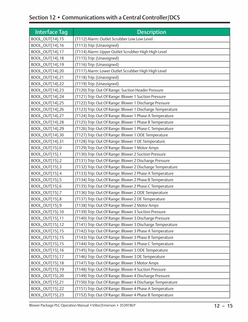
12 – 15
Section 12 • Communications with a Central Controller/DCS
Blower Package PLC Operation Manual •Vilter/Emerson • 35391BLP
Interface Tag DescriptionBOOL_OUT[14].15 (T112) Alarm: Outlet Scrubber Low Low Level
BOOL_OUT[14].16 (T113) Trip: (Unassigned)
BOOL_OUT[14].17 (T114) Alarm: Upper Outlet Scrubber High High Level
BOOL_OUT[14].18 (T115) Trip: (Unassigned)
BOOL_OUT[14].19 (T116) Trip: (Unassigned)
BOOL_OUT[14].20 (T117) Alarm: Lower Outlet Scrubber High High Level
BOOL_OUT[14].21 (T118) Trip: (Unassigned)
BOOL_OUT[14].22 (T119) Trip: (Unassigned)
BOOL_OUT[14].23 (T120) Trip: Out Of Range: Suction Header Pressure
BOOL_OUT[14].24 (T121) Trip: Out Of Range: Blower 1 Suction Pressure
BOOL_OUT[14].25 (T122) Trip: Out Of Range: Blower 1 Discharge Pressure
BOOL_OUT[14].26 (T123) Trip: Out Of Range: Blower 1 Discharge Temperature
BOOL_OUT[14].27 (T124) Trip: Out Of Range: Blower 1 Phase A Temperature
BOOL_OUT[14].28 (T125) Trip: Out Of Range: Blower 1 Phase B Temperature
BOOL_OUT[14].29 (T126) Trip: Out Of Range: Blower 1 Phase C Temperature
BOOL_OUT[14].30 (T127) Trip: Out Of Range: Blower 1 ODE Temperature
BOOL_OUT[14].31 (T128) Trip: Out Of Range: Blower 1 DE Temperature
BOOL_OUT[15].0 (T129) Trip: Out Of Range: Blower 1 Motor Amps
BOOL_OUT[15].1 (T130) Trip: Out Of Range: Blower 2 Suction Pressure
BOOL_OUT[15].2 (T131) Trip: Out Of Range: Blower 2 Discharge Pressure
BOOL_OUT[15].3 (T132) Trip: Out Of Range: Blower 2 Discharge Temperature
BOOL_OUT[15].4 (T133) Trip: Out Of Range: Blower 2 Phase A Temperature
BOOL_OUT[15].5 (T134) Trip: Out Of Range: Blower 2 Phase B Temperature
BOOL_OUT[15].6 (T135) Trip: Out Of Range: Blower 2 Phase C Temperature
BOOL_OUT[15].7 (T136) Trip: Out Of Range: Blower 2 ODE Temperature
BOOL_OUT[15].8 (T137) Trip: Out Of Range: Blower 2 DE Temperature
BOOL_OUT[15].9 (T138) Trip: Out Of Range: Blower 2 Motor Amps
BOOL_OUT[15].10 (T139) Trip: Out Of Range: Blower 3 Suction Pressure
BOOL_OUT[15].11 (T140) Trip: Out Of Range: Blower 3 Discharge Pressure
BOOL_OUT[15].12 (T141) Trip: Out Of Range: Blower 3 Discharge Temperature
BOOL_OUT[15].15 (T142) Trip: Out Of Range: Blower 3 Phase A Temperature
BOOL_OUT[15].15 (T143) Trip: Out Of Range: Blower 3 Phase B Temperature
BOOL_OUT[15].15 (T144) Trip: Out Of Range: Blower 3 Phase C Temperature
BOOL_OUT[15].16 (T145) Trip: Out Of Range: Blower 3 ODE Temperature
BOOL_OUT[15].17 (T146) Trip: Out Of Range: Blower 3 DE Temperature
BOOL_OUT[15].18 (T147) Trip: Out Of Range: Blower 3 Motor Amps
BOOL_OUT[15].19 (T148) Trip: Out Of Range: Blower 4 Suction Pressure
BOOL_OUT[15].20 (T149) Trip: Out Of Range: Blower 4 Discharge Pressure
BOOL_OUT[15].21 (T150) Trip: Out Of Range: Blower 4 Discharge Temperature
BOOL_OUT[15].22 (T151) Trip: Out Of Range: Blower 4 Phase A Temperature
BOOL_OUT[15].23 (T152) Trip: Out Of Range: Blower 4 Phase B Temperature
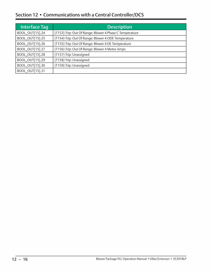
12 – 16
Section 12 • Communications with a Central Controller/DCS
Blower Package PLC Operation Manual •Vilter/Emerson • 35391BLP
Interface Tag DescriptionBOOL_OUT[15].24 (T153) Trip: Out Of Range: Blower 4 Phase C Temperature
BOOL_OUT[15].25 (T154) Trip: Out Of Range: Blower 4 ODE Temperature
BOOL_OUT[15].26 (T155) Trip: Out Of Range: Blower 4 DE Temperature
BOOL_OUT[15].27 (T156) Trip: Out Of Range: Blower 4 Motor Amps
BOOL_OUT[15].28 (T157) Trip: Unassigned
BOOL_OUT[15].29 (T158) Trip: Unassigned
BOOL_OUT[15].30 (T159) Trip: Unassigned
BOOL_OUT[15].31
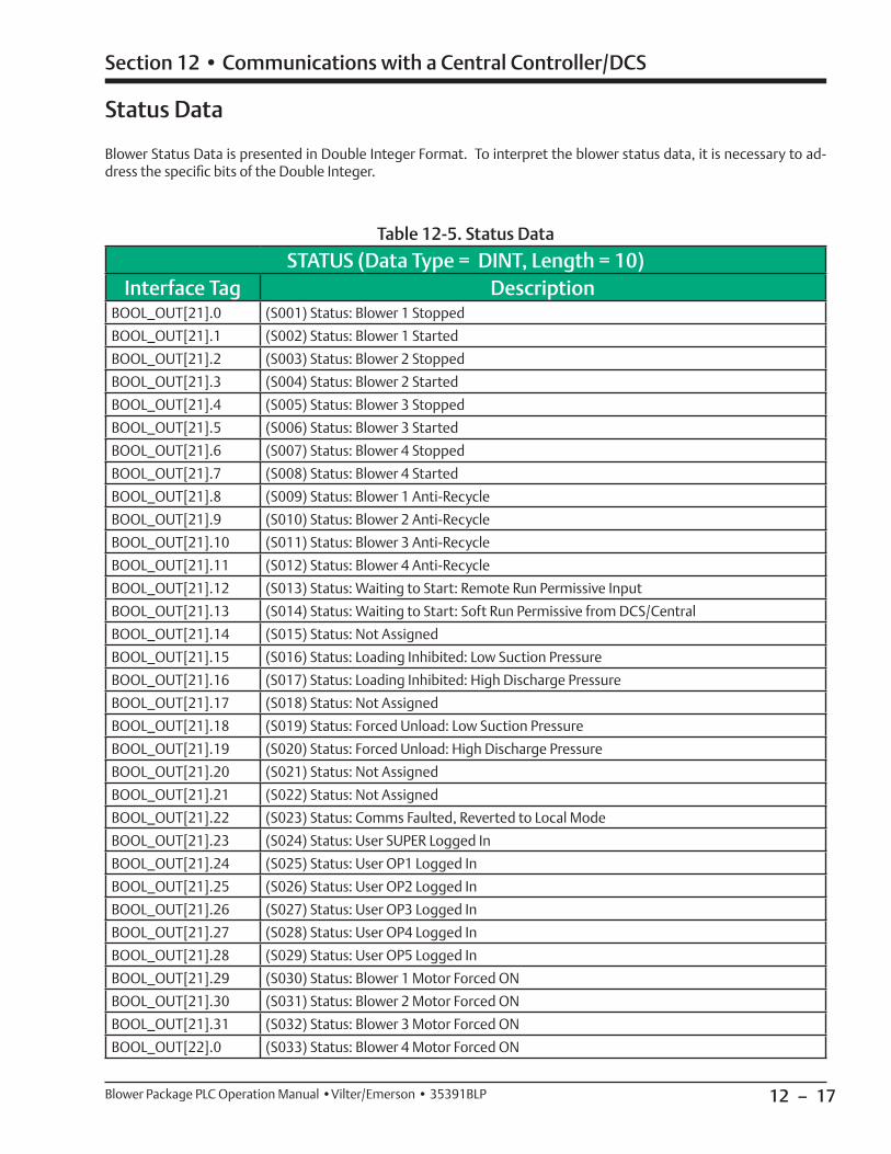
12 – 17
Section 12 • Communications with a Central Controller/DCS
Blower Package PLC Operation Manual •Vilter/Emerson • 35391BLP
STATUS (Data Type = DINT, Length = 10)Interface Tag Description
BOOL_OUT[21].0 (S001) Status: Blower 1 Stopped
BOOL_OUT[21].1 (S002) Status: Blower 1 Started
BOOL_OUT[21].2 (S003) Status: Blower 2 Stopped
BOOL_OUT[21].3 (S004) Status: Blower 2 Started
BOOL_OUT[21].4 (S005) Status: Blower 3 Stopped
BOOL_OUT[21].5 (S006) Status: Blower 3 Started
BOOL_OUT[21].6 (S007) Status: Blower 4 Stopped
BOOL_OUT[21].7 (S008) Status: Blower 4 Started
BOOL_OUT[21].8 (S009) Status: Blower 1 Anti-Recycle
BOOL_OUT[21].9 (S010) Status: Blower 2 Anti-Recycle
BOOL_OUT[21].10 (S011) Status: Blower 3 Anti-Recycle
BOOL_OUT[21].11 (S012) Status: Blower 4 Anti-Recycle
BOOL_OUT[21].12 (S013) Status: Waiting to Start: Remote Run Permissive Input
BOOL_OUT[21].13 (S014) Status: Waiting to Start: Soft Run Permissive from DCS/Central
BOOL_OUT[21].14 (S015) Status: Not Assigned
BOOL_OUT[21].15 (S016) Status: Loading Inhibited: Low Suction Pressure
BOOL_OUT[21].16 (S017) Status: Loading Inhibited: High Discharge Pressure
BOOL_OUT[21].17 (S018) Status: Not Assigned
BOOL_OUT[21].18 (S019) Status: Forced Unload: Low Suction Pressure
BOOL_OUT[21].19 (S020) Status: Forced Unload: High Discharge Pressure
BOOL_OUT[21].20 (S021) Status: Not Assigned
BOOL_OUT[21].21 (S022) Status: Not Assigned
BOOL_OUT[21].22 (S023) Status: Comms Faulted, Reverted to Local Mode
BOOL_OUT[21].23 (S024) Status: User SUPER Logged In
BOOL_OUT[21].24 (S025) Status: User OP1 Logged In
BOOL_OUT[21].25 (S026) Status: User OP2 Logged In
BOOL_OUT[21].26 (S027) Status: User OP3 Logged In
BOOL_OUT[21].27 (S028) Status: User OP4 Logged In
BOOL_OUT[21].28 (S029) Status: User OP5 Logged In
BOOL_OUT[21].29 (S030) Status: Blower 1 Motor Forced ON
BOOL_OUT[21].30 (S031) Status: Blower 2 Motor Forced ON
BOOL_OUT[21].31 (S032) Status: Blower 3 Motor Forced ON
BOOL_OUT[22].0 (S033) Status: Blower 4 Motor Forced ON
Status Data
Blower Status Data is presented in Double Integer Format. To interpret the blower status data, it is necessary to ad-dress the specifi c bits of the Double Integer.
Table 12-5. Status Data
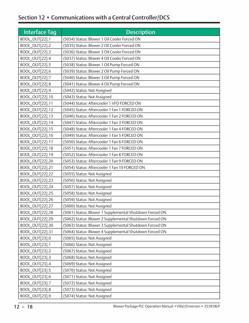
12 – 18
Section 12 • Communications with a Central Controller/DCS
Blower Package PLC Operation Manual •Vilter/Emerson • 35391BLP
Interface Tag DescriptionBOOL_OUT[22].1 (S034) Status: Blower 1 Oil Cooler Forced ON
BOOL_OUT[22].2 (S035) Status: Blower 2 Oil Cooler Forced ON
BOOL_OUT[22].3 (S036) Status: Blower 3 Oil Cooler Forced ON
BOOL_OUT[22].4 (S037) Status: Blower 4 Oil Cooler Forced ON
BOOL_OUT[22].5 (S038) Status: Blower 1 Oil Pump Forced ON
BOOL_OUT[22].6 (S039) Status: Blower 2 Oil Pump Forced ON
BOOL_OUT[22].7 (S040) Status: Blower 3 Oil Pump Forced ON
BOOL_OUT[22].8 (S041) Status: Blower 4 Oil Pump Forced ON
BOOL_OUT[22].9 (S042) Status: Not Assigned
BOOL_OUT[22].10 (S043) Status: Not Assigned
BOOL_OUT[22].11 (S044) Status: Aftercooler 1 VFD FORCED ON
BOOL_OUT[22].12 (S045) Status: Aftercooler 1 Fan 1 FORCED ON
BOOL_OUT[22].13 (S046) Status: Aftercooler 1 Fan 2 FORCED ON
BOOL_OUT[22].14 (S047) Status: Aftercooler 1 Fan 3 FORCED ON
BOOL_OUT[22].15 (S048) Status: Aftercooler 1 Fan 4 FORCED ON
BOOL_OUT[22].16 (S049) Status: Aftercooler 1 Fan 5 FORCED ON
BOOL_OUT[22].17 (S050) Status: Aftercooler 1 Fan 6 FORCED ON
BOOL_OUT[22].18 (S051) Status: Aftercooler 1 Fan 7 FORCED ON
BOOL_OUT[22].19 (S052) Status: Aftercooler 1 Fan 8 FORCED ON
BOOL_OUT[22].20 (S053) Status: Aftercooler 1 Fan 9 FORCED ON
BOOL_OUT[22].21 (S054) Status: Aftercooler 1 Fan 10 FORCED ON
BOOL_OUT[22].22 (S055) Status: Not Assigned
BOOL_OUT[22].23 (S056) Status: Not Assigned
BOOL_OUT[22].24 (S057) Status: Not Assigned
BOOL_OUT[22].25 (S058) Status: Not Assigned
BOOL_OUT[22].26 (S059) Status: Not Assigned
BOOL_OUT[22].27 (S060) Status: Not Assigned
BOOL_OUT[22].28 (S061) Status: Blower 1 Supplemental Shutdown Forced ON
BOOL_OUT[22].29 (S062) Status: Blower 2 Supplemental Shutdown Forced ON
BOOL_OUT[22].30 (S063) Status: Blower 3 Supplemental Shutdown Forced ON
BOOL_OUT[22].31 (S064) Status: Blower 4 Supplemental Shutdown Forced ON
BOOL_OUT[23].0 (S065) Status: Not Assigned
BOOL_OUT[23].1 (S066) Status: Not Assigned
BOOL_OUT[23].2 (S067) Status: Not Assigned
BOOL_OUT[23].3 (S068) Status: Not Assigned
BOOL_OUT[23].4 (S069) Status: Not Assigned
BOOL_OUT[23].5 (S070) Status: Not Assigned
BOOL_OUT[23].6 (S071) Status: Not Assigned
BOOL_OUT[23].7 (S072) Status: Not Assigned
BOOL_OUT[23].8 (S073) Status: Not Assigned
BOOL_OUT[23].9 (S074) Status: Not Assigned
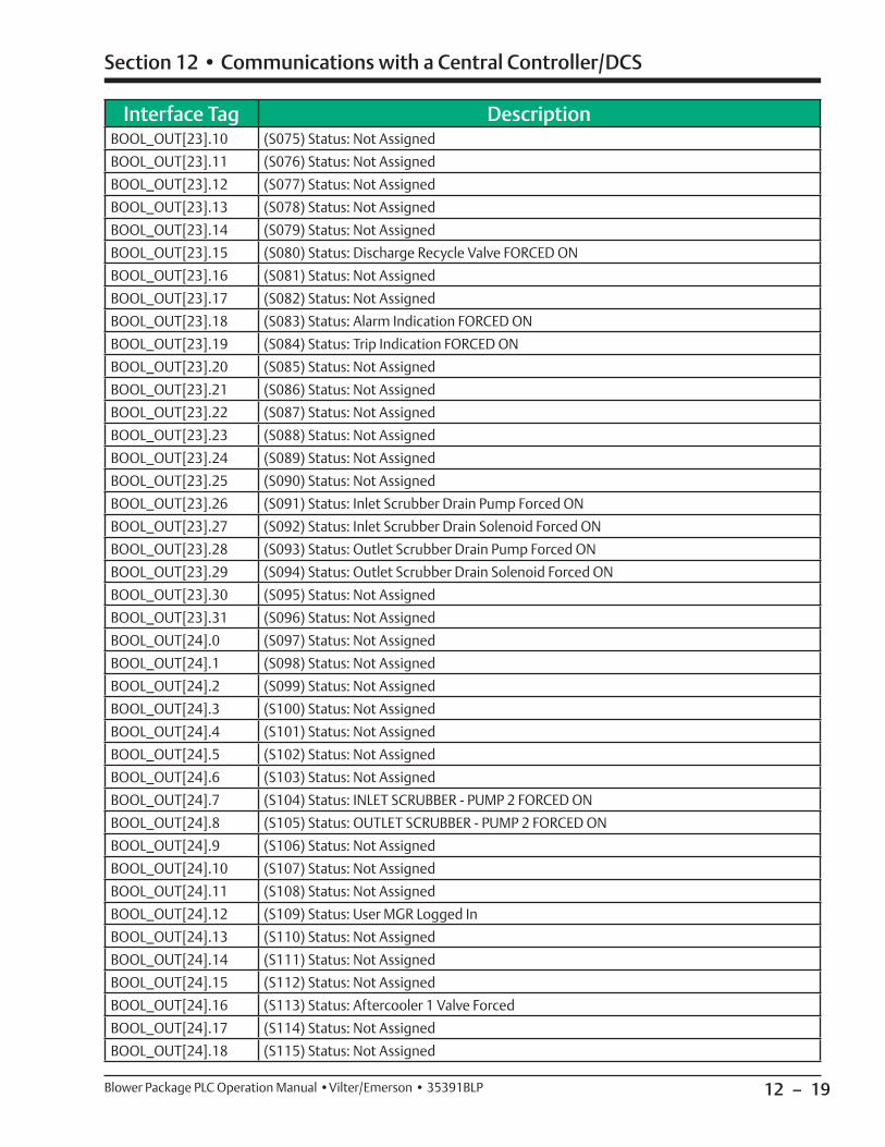
12 – 19
Section 12 • Communications with a Central Controller/DCS
Blower Package PLC Operation Manual •Vilter/Emerson • 35391BLP
Interface Tag DescriptionBOOL_OUT[23].10 (S075) Status: Not Assigned
BOOL_OUT[23].11 (S076) Status: Not Assigned
BOOL_OUT[23].12 (S077) Status: Not Assigned
BOOL_OUT[23].13 (S078) Status: Not Assigned
BOOL_OUT[23].14 (S079) Status: Not Assigned
BOOL_OUT[23].15 (S080) Status: Discharge Recycle Valve FORCED ON
BOOL_OUT[23].16 (S081) Status: Not Assigned
BOOL_OUT[23].17 (S082) Status: Not Assigned
BOOL_OUT[23].18 (S083) Status: Alarm Indication FORCED ON
BOOL_OUT[23].19 (S084) Status: Trip Indication FORCED ON
BOOL_OUT[23].20 (S085) Status: Not Assigned
BOOL_OUT[23].21 (S086) Status: Not Assigned
BOOL_OUT[23].22 (S087) Status: Not Assigned
BOOL_OUT[23].23 (S088) Status: Not Assigned
BOOL_OUT[23].24 (S089) Status: Not Assigned
BOOL_OUT[23].25 (S090) Status: Not Assigned
BOOL_OUT[23].26 (S091) Status: Inlet Scrubber Drain Pump Forced ON
BOOL_OUT[23].27 (S092) Status: Inlet Scrubber Drain Solenoid Forced ON
BOOL_OUT[23].28 (S093) Status: Outlet Scrubber Drain Pump Forced ON
BOOL_OUT[23].29 (S094) Status: Outlet Scrubber Drain Solenoid Forced ON
BOOL_OUT[23].30 (S095) Status: Not Assigned
BOOL_OUT[23].31 (S096) Status: Not Assigned
BOOL_OUT[24].0 (S097) Status: Not Assigned
BOOL_OUT[24].1 (S098) Status: Not Assigned
BOOL_OUT[24].2 (S099) Status: Not Assigned
BOOL_OUT[24].3 (S100) Status: Not Assigned
BOOL_OUT[24].4 (S101) Status: Not Assigned
BOOL_OUT[24].5 (S102) Status: Not Assigned
BOOL_OUT[24].6 (S103) Status: Not Assigned
BOOL_OUT[24].7 (S104) Status: INLET SCRUBBER - PUMP 2 FORCED ON
BOOL_OUT[24].8 (S105) Status: OUTLET SCRUBBER - PUMP 2 FORCED ON
BOOL_OUT[24].9 (S106) Status: Not Assigned
BOOL_OUT[24].10 (S107) Status: Not Assigned
BOOL_OUT[24].11 (S108) Status: Not Assigned
BOOL_OUT[24].12 (S109) Status: User MGR Logged In
BOOL_OUT[24].13 (S110) Status: Not Assigned
BOOL_OUT[24].14 (S111) Status: Not Assigned
BOOL_OUT[24].15 (S112) Status: Not Assigned
BOOL_OUT[24].16 (S113) Status: Aftercooler 1 Valve Forced
BOOL_OUT[24].17 (S114) Status: Not Assigned
BOOL_OUT[24].18 (S115) Status: Not Assigned

12 – 20
Section 12 • Communications with a Central Controller/DCS
Blower Package PLC Operation Manual •Vilter/Emerson • 35391BLP
Interface Tag DescriptionBOOL_OUT[24].19 (S116) Status: Not Assigned
BOOL_OUT[24].20 (S117) Status: Not Assigned
BOOL_OUT[24].21 (S118) Status: Rung Edit Detected
BOOL_OUT[24].22 (S119) Status: Not Assigned
BOOL_OUT[24].23 (S120) Status: Not Assigned
BOOL_OUT[24].24 (S121) Status: Not Assigned
BOOL_OUT[24].25 (S122) Status: Not Assigned

12 – 21
Section 12 • Communications with a Central Controller/DCS
Blower Package PLC Operation Manual •Vilter/Emerson • 35391BLP
States of Discrete I/O
States of the Discrete Inputs and Outputs is presented in Double Integer Format. To interpret the IO State data, it is necessary to address the specifi c bits of the Double Integer.
Discrete Input States (Data Type = DINT)Interface Tag Description
BOOL_OUT[31].0 Aftercooler 1 Fan Aux Contact (Step Type)
BOOL_OUT[31].1 Aftercooler 1 Fan Aux Contact (Step Type)
BOOL_OUT[31].2 Aftercooler 1 Fan Aux Contact (Step Type)
BOOL_OUT[31].3 Aftercooler 1 Fan Aux Contact (Step Type)
BOOL_OUT[31].4 Aftercooler 1 Fan Aux Contact (Step Type)
BOOL_OUT[31].5 Aftercooler 1 Fan Aux Contact (Step Type)
BOOL_OUT[31].6 Aftercooler 1 Fan Aux Contact (Step Type)
BOOL_OUT[31].7 Aftercooler 1 Fan Aux Contact (Step Type)
BOOL_OUT[31].8 Aftercooler 1 Fan Aux Contact (Step Type)
BOOL_OUT[31].9 Aftercooler 1 Fan Aux Contact (Step Type)
BOOL_OUT[31].10 Aftercooler 1 VFD Faulted (VFD Type)
BOOL_OUT[31].11 Aftercooler 1 VFD Running
BOOL_OUT[31].12 Blower 1 Oil Pressure Switch (1=OK)
BOOL_OUT[31].13 Blower 1 Oil Cooler Fan Running
BOOL_OUT[31].14 Blower 1 Oil Pump Running
BOOL_OUT[31].15 Blower 1 VFD Faulted (0=Faulted)
BOOL_OUT[31].16 Blower 1 VFD Running
BOOL_OUT[31].17 Blower 2 Oil Pressure Switch (1=OK)
BOOL_OUT[31].18 Blower 2 Oil Cooler Fan Running
BOOL_OUT[31].19 Blower 2 Oil Pump Running
BOOL_OUT[31].20 Blower 2 VFD Faulted (0=Faulted)
BOOL_OUT[31].21 Blower 2 VFD Running
BOOL_OUT[31].22 Blower 3 Oil Pressure Switch (1=OK)
BOOL_OUT[31].23 Blower 3 Oil Cooler Fan Running
BOOL_OUT[31].24 Blower 3 Oil Pump Running
BOOL_OUT[31].25 Blower 3 VFD Faulted (0=Faulted)
BOOL_OUT[31].26 Blower 3 VFD Running
BOOL_OUT[31].27 Blower 4 Oil Pressure Switch (1=OK)
BOOL_OUT[31].28 Blower 4 Oil Cooler Fan Running
BOOL_OUT[31].29 Blower 4 Oil Pump Running
BOOL_OUT[31].30 Blower 4 VFD Faulted (0=Faulted)
BOOL_OUT[31].31 Blower 4 VFD Running
BOOL_OUT[32].0 E-stop OK and MCR energized
Table 12-6. Discrete Input
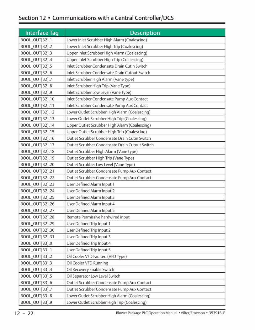
12 – 22
Section 12 • Communications with a Central Controller/DCS
Blower Package PLC Operation Manual •Vilter/Emerson • 35391BLP
Interface Tag DescriptionBOOL_OUT[32].1 Lower Inlet Scrubber High Alarm (Coalescing)
BOOL_OUT[32].2 Lower Inlet Scrubber High Trip (Coalescing)
BOOL_OUT[32].3 Upper Inlet Scrubber High Alarm (Coalescing)
BOOL_OUT[32].4 Upper Inlet Scrubber High Trip (Coalescing)
BOOL_OUT[32].5 Inlet Scrubber Condensate Drain Cutin Switch
BOOL_OUT[32].6 Inlet Scrubber Condensate Drain Cutout Switch
BOOL_OUT[32].7 Inlet Scrubber High Alarm (Vane type)
BOOL_OUT[32].8 Inlet Scrubber High Trip (Vane Type)
BOOL_OUT[32].9 Inlet Scrubber Low Level (Vane Type)
BOOL_OUT[32].10 Inlet Scrubber Condensate Pump Aux Contact
BOOL_OUT[32].11 Inlet Scrubber Condensate Pump Aux Contact
BOOL_OUT[32].12 Lower Outlet Scrubber High Alarm (Coalescing)
BOOL_OUT[32].13 Lower Outlet Scrubber High Trip (Coalescing)
BOOL_OUT[32].14 Upper Outlet Scrubber High Alarm (Coalescing)
BOOL_OUT[32].15 Upper Outlet Scrubber High Trip (Coalescing)
BOOL_OUT[32].16 Outlet Scrubber Condensate Drain Cutin Switch
BOOL_OUT[32].17 Outlet Scrubber Condensate Drain Cutout Switch
BOOL_OUT[32].18 Outlet Scrubber High Alarm (Vane type)
BOOL_OUT[32].19 Outlet Scrubber High Trip (Vane Type)
BOOL_OUT[32].20 Outlet Scrubber Low Level (Vane Type)
BOOL_OUT[32].21 Outlet Scrubber Condensate Pump Aux Contact
BOOL_OUT[32].22 Outlet Scrubber Condensate Pump Aux Contact
BOOL_OUT[32].23 User Defi ned Alarm Input 1
BOOL_OUT[32].24 User Defi ned Alarm Input 2
BOOL_OUT[32].25 User Defi ned Alarm Input 3
BOOL_OUT[32].26 User Defi ned Alarm Input 4
BOOL_OUT[32].27 User Defi ned Alarm Input 5
BOOL_OUT[32].28 Remote Permissive hardwired input
BOOL_OUT[32].29 User Defi ned Trip Input 1
BOOL_OUT[32].30 User Defi ned Trip Input 2
BOOL_OUT[32].31 User Defi ned Trip Input 3
BOOL_OUT[33].0 User Defi ned Trip Input 4
BOOL_OUT[33].1 User Defi ned Trip Input 5
BOOL_OUT[33].2 Oil Cooler VFD Faulted (VFD Type)
BOOL_OUT[33].3 Oil Cooler VFD Running
BOOL_OUT[33].4 Oil Recovery Enable Switch
BOOL_OUT[33].5 Oil Separator Low Level Switch
BOOL_OUT[33].6 Outlet Scrubber Condensate Pump Aux Contact
BOOL_OUT[33].7 Outlet Scrubber Condensate Pump Aux Contact
BOOL_OUT[33].8 Lower Outlet Scrubber High Alarm (Coalescing)
BOOL_OUT[33].9 Lower Outlet Scrubber High Trip (Coalescing)

12 – 23
Section 12 • Communications with a Central Controller/DCS
Blower Package PLC Operation Manual •Vilter/Emerson • 35391BLP
Discrete Output States (Data Type = DINT)Interface Tag Description
BOOL_OUT[36].0 Aftercooler 1 Fan Starter (Step Type)
BOOL_OUT[36].1 Aftercooler 1 Fan Starter (Step Type)
BOOL_OUT[36].2 Aftercooler 1 Fan Starter (Step Type)
BOOL_OUT[36].3 Aftercooler 1 Fan Starter (Step Type)
BOOL_OUT[36].4 Aftercooler 1 Fan Starter (Step Type)
BOOL_OUT[36].5 Aftercooler 1 Fan Starter (Step Type)
BOOL_OUT[36].6 Aftercooler 1 Fan Starter (Step Type)
BOOL_OUT[36].7 Aftercooler 1 Fan Starter (Step Type)
BOOL_OUT[36].8 Aftercooler 1 Fan Starter (Step Type)
BOOL_OUT[36].9 Aftercooler 1 Fan Starter (Step Type)
BOOL_OUT[36].10 Aftercooler 1 Fan Starter (Step Type)
BOOL_OUT[36].11 Aftercooler 1 VFD Start Command
BOOL_OUT[36].12 Alarm Indication (0=ALARM)
BOOL_OUT[36].13 Blower 1 Shunt Trip Output
Interface Tag DescriptionBOOL_OUT[33].10 Upper Outlet Scrubber High Alarm (Coalescing)
BOOL_OUT[33].11 Upper Outlet Scrubber High Trip (Coalescing)
BOOL_OUT[33].12 Outlet Scrubber Condensate Drain Cutin Switch
BOOL_OUT[33].13 Outlet Scrubber Condensate Drain Cutout Switch
BOOL_OUT[33].14 Outlet Scrubber High Alarm (Vane type)
BOOL_OUT[33].15 Outlet Scrubber High Trip (Vane Type)
BOOL_OUT[33].16 Outlet Scrubber Low Level (Vane Type)
BOOL_OUT[33].17 User Defi ned Alarm Input 1
BOOL_OUT[33].18 User Defi ned Alarm Input 2
BOOL_OUT[33].19 User Defi ned Alarm Input 3
BOOL_OUT[33].20 User Defi ned Alarm Input 4
BOOL_OUT[33].21 User Defi ned Alarm Input 5
BOOL_OUT[33].22 Remote Manual Capacity Decrease Input
BOOL_OUT[33].23 Remote Manual Capacity Increase Input
BOOL_OUT[33].24 Remote Permissive hardwired input
BOOL_OUT[33].25 User Defi ned Trip Input 1
BOOL_OUT[33].26 User Defi ned Trip Input 2
BOOL_OUT[33].27 User Defi ned Trip Input 3
BOOL_OUT[33].28 User Defi ned Trip Input 4
BOOL_OUT[33].29 User Defi ned Trip Input 5
BOOL_OUT[33].30 Smoke Detector Input
BOOL_OUT[33].31
Table 12-7. Discrete Output
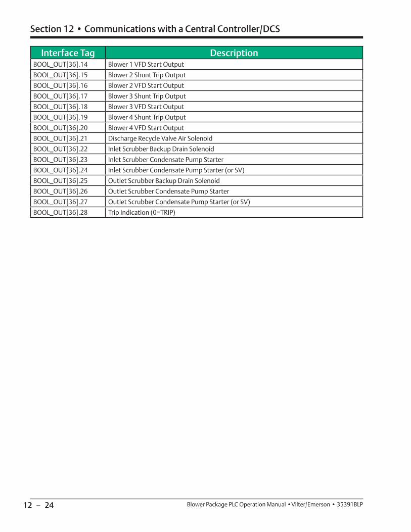
12 – 24
Section 12 • Communications with a Central Controller/DCS
Blower Package PLC Operation Manual •Vilter/Emerson • 35391BLP
Interface Tag DescriptionBOOL_OUT[36].14 Blower 1 VFD Start Output
BOOL_OUT[36].15 Blower 2 Shunt Trip Output
BOOL_OUT[36].16 Blower 2 VFD Start Output
BOOL_OUT[36].17 Blower 3 Shunt Trip Output
BOOL_OUT[36].18 Blower 3 VFD Start Output
BOOL_OUT[36].19 Blower 4 Shunt Trip Output
BOOL_OUT[36].20 Blower 4 VFD Start Output
BOOL_OUT[36].21 Discharge Recycle Valve Air Solenoid
BOOL_OUT[36].22 Inlet Scrubber Backup Drain Solenoid
BOOL_OUT[36].23 Inlet Scrubber Condensate Pump Starter
BOOL_OUT[36].24 Inlet Scrubber Condensate Pump Starter (or SV)
BOOL_OUT[36].25 Outlet Scrubber Backup Drain Solenoid
BOOL_OUT[36].26 Outlet Scrubber Condensate Pump Starter
BOOL_OUT[36].27 Outlet Scrubber Condensate Pump Starter (or SV)
BOOL_OUT[36].28 Trip Indication (0=TRIP)
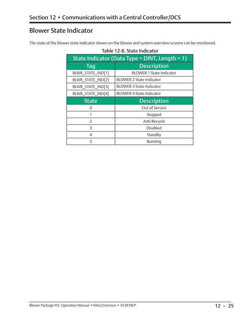
12 – 25
Section 12 • Communications with a Central Controller/DCS
Blower Package PLC Operation Manual •Vilter/Emerson • 35391BLP
Blower State Indicator
The state of the blower state indicator shown on the blower and system overview screens can be monitored.
State Indicator (Data Type = DINT, Length = 1)Tag Description
BLWR_STATE_IND[1] BLOWER 1 State Indicator
BLWR_STATE_IND[2] BLOWER 2 State Indicator
BLWR_STATE_IND[3] BLOWER 3 State Indicator
BLWR_STATE_IND[4] BLOWER 4 State Indicator
State Description0 Out of Service
1 Stopped
2 Anti-Recycle
3 Disabled
4 Standby
5 Running
Table 12-8. State Indicator

12 – 26
Section 12 • Communications with a Central Controller/DCS
Blower Package PLC Operation Manual •Vilter/Emerson • 35391BLP
Blower Commands: “REAL_IN” (Data Type = REAL)Interface Tag Description Units
REAL_IN[0] Remote Discharge Pressure Setpoint PSIA
REAL_IN[1]
REAL_IN[2] Remote Suction Pressure Setpoint PSIA
REAL_IN[3] Common Discharge Header Pressure From DCS PSIA
REAL_IN[4] Common Suction Header Pressure From DCS PSIA
REAL_IN[5] Blower 1 Remote Manual Speed % Speed
REAL_IN[6] Blower 2 Remote Manual Speed % Speed
REAL_IN[7] Blower 3 Remote Manual Speed % Speed
REAL_IN[8] Blower 4 Remote Manual Speed % Speed
Table 12-9. Blower Command (Real)
DISCRETE BLOWER COMMANDS
Discrete Blower commands are presented in Double Integer Format. To send discrete commands, it is neces-sary to address the specifi c bits of the Double Integer.
If Control by communications is enabled from the
Write Data: “BOOL_IN” (Data Type = DINT)Interface Tag Description
BOOL_IN[1].0
BOOL_IN[1].1 Blower 1 Remote Enable (1=Enable)
BOOL_IN[1].2 Blower 2 Remote Enable (1=Enable)
BOOL_IN[1].3 Blower 3 Remote Enable (1=Enable)
BOOL_IN[1].4 Blower 4 Remote Enable (1=Enable)
BOOL_IN[1].5
BOOL_IN[1].6 Local Mode Command from DCS
BOOL_IN[1].7 Remote Mode Command from DCS
BOOL_IN[1].8 Reset Alarms from DCS
BOOL_IN[1].9 Soft Run Command from DCS
Table 12-10. Blower Command (Double Integer)
Confi guration Screen, the soft run command (BOOL_IN[1].5) must be held HIGH in addition to the remote permissive physical input.
Data that can be Written to the Blower PLC
To send commands to the Blower PLC, Control by Communications must be enabled from the Confi guration screen and the watchdog must show that communications between the Blower PLC and Central Controller/DCS are not faulted. On a communication fault, the commands from the Central controller will stay in their last state/value in the blower PLC.


35391BLP Rev. 0 (9/13) Emerson and Vilter are trademarks of Emerson Electric Co. or one of its affi liated companies. © 2013 Emerson Climate Technologies, Inc. All rights reserved. Printed in the USA.