blp30 ac-dc series data sheet 30 watts
TRANSCRIPT

MCD10026 Rev. 1.0 Page 1 of 6 www.power-one.com
BLP30 AC-DC Series Data Sheet30 Watts
Description
The BLP30 Series’ economical and compact construction provides single or three-output AC to DC power conversion to meet the requirements of most commercial and industrial applications.
Single-Output Model Selection Model Nominal
Output Voltage (VDC)
Min-Max Output Current (Amps),
Convection
Min-Max Output Current (Amps),
Forced Air 1
Peak Output Current (Amps) 2
Total Regulation
(%) 3
Ripple & Noise
pk-pk % 4 BLP30-1005G 5V 0 – 5 0 – 6 7.2 ± 2 1
BLP30-1012G 12V 0 – 2.1 0 – 2.5 3.0 ± 2 1
BLP30-1024G 24V 0 – 1.0 0 – 1.25 1.5 ± 2 0.6
Triple-Output Model Selection Model Nominal
Output Voltage (VDC)
Min-Max Output Current (Amps),
Convection
Min-Max Output Current (Amps),
Forced Air 1
Peak Output Current (Amps) 2
Total Regulation
(%) 3
Ripple & Noise
pk-pk % 4 +5V 0.2 – 2.5 0.2 – 3.5 5 ±2 1%
BLP30-3000G +12V 0.1 – 1.2 0.1 – 2.0 3 ±5 1%
-12V 0.0 – 0.3 0.0 – 0.5 1 ±5 1%
1 10 CFM or 260 LFM (average measurement of six equally-distributed points through a 3.5" x 1.6" (9 cm x 4 cm) cross-sectional area with power supply mounted on a 0.25" (6.35 mm) standoffs. Recommended airflow direction is from the AC input to the DC output.
2 Peak current duration for less than 30 seconds with a max duty cycle of 10%. 3 At 25 °C ambient including voltage set point tolerance, line, and load regulation 4 Maximum peak-to-peak noise expressed as a percentage of output voltage, 20 MHz bandwidth, measured with a twisted pair differentially
across a 10 µF E-cap and a 0.1 µF ceramic cap in parallel. The point of measurement is within 1 cm of the output connection. Model numbers highlighted in yellow or shaded are not recommended for new designs.
Applications
• Datacom (hubs, routers) • POS terminals • Industrial • Cable modems • External disk storage • Medical instrumentation • Computers
Features • RoHS compliant for all six substances • 2” x 4” footprint • Component height less than 1” • 25 W rating with natural convection cooling • 30 W rating with 10 CFM airflow • Compliance to EMI Class B • Universal AC input • Short-circuit protection • Overvoltage protection • CE marked to Low Voltage Directive (Pending) • Compliance to EN61000-4-2/-3/-4/-5/-6/-8/-11 • Two-year warranty
Courtesy of Steven Engineering, Inc.-230 Ryan Way, South San Francisco, CA 94080-6370-Main Office: (650) 588-9200-Outside Local Area: (800) 258-9200-www.stevenengineering.com

MCD10026 Rev. 1.0 Page 2 of 6 www.power-one.com
BLP30 AC-DC Series Data Sheet30 Watts
ELECTRICAL SPECIFICATIONS
Input Specifications Parameter Conditions/Description Min. Nom. Max. Units
Input Voltage - AC Single-phase continuous input range 90 100 - 250 264 VAC
Input Voltage - DC 127 160/325 375 VDC
Input Frequency AC Input 47 50 - 60 63 Hz
Input Current At 90 VAC input., 30W 0.75 A rms
Inrush Surge Current Internally limited. 115 VAC, Max Power, 25 °C Internally limited. 230 VAC, Max Power, 25 °C
16 32
A pk A pk
Input fuse Non-user serviceable internally located AC input line fuse is provided.
Efficiency At maximum output power. 70 75 %
Switching Frequency 60 69 kHz
Output Specifications Parameter Conditions/Description Min. Nom. Max. Units
Output power With convection cooling. See Model Selection. With forced-air cooling. See Model Selection.
25 30
Watts
Load transient Vo1, Vo2, or Vo3 deviation due to a 50 to 100%load change at a rate of 1A/µs.
±5 %
Turn on Delay Time required for outputs to be within regulation after initial application of AC input.
1.5 Sec
Rise Time Time required for output voltage to rise from 10% to 90%.
20 ms
Hold-up Time At 30W, 115 VAC, 60 Hz. 20 Ms
Overvoltage Protection Main output. 5V: 12V: 24V:
5.6 14.0 29.0
6.9 16.7 34.2
V
Short-circuit Protection Fully-protected against output short circuit.
Overshoot Single-output models. 2 %
Overshoot Triple-output models. 5 %
Courtesy of Steven Engineering, Inc.-230 Ryan Way, South San Francisco, CA 94080-6370-Main Office: (650) 588-9200-Outside Local Area: (800) 258-9200-www.stevenengineering.com

MCD10026 Rev. 1.0 Page 3 of 6 www.power-one.com
BLP30 AC-DC Series Data Sheet30 Watts
Regulatory & Safety Approvals
Parameter Conditions/Description Min. Nom. Max. Units UL60950-1 All models are approved.
CSA-C22.2, No. 60950-1-03
All models are approved.
EN 60950-1 /IEC 60950-1
All models are approved.
CE Mark for LVD All models are approved.
CB Approval Completed.
Ground Continuity At 12 VDC. 30 A
Dielectric Withstand Voltage
Input-to-Ground (Basic) . Input-to-Output (Reinforced). The primary to secondary test is not performed on completed assemblies. Output-to-Ground (Functional).
2121
4242
500
VDC
VDC
VDC
Electromagnetic Interference
FCC Part 15. Conducted: CISPR 22 and CISPR 11. Conducted:
B B
Class
ESD Per EN 61000-4-2, level 2.
Radiated Susceptibility Per EN 61000-4-3, level 3. 3 V/m
EFT/Burst Per EN 61000-4-4, level 3. 1 kV
Input Transient Protection
Per EN 61000-4-5, class 3. Line-to-Line: Line-to-Ground:
1 2
kV
RF Immunity Per EN 61000-4-6, level 3. 3 V/m
Magnetic Fields Per EN 61000-4-8. 1 A/m
Voltage Interruptions Per EN 61000-4-11
Leakage Current Per EN 60950 At 115 VAC: At 230 VAC:
0.2 0.4
mA
Courtesy of Steven Engineering, Inc.-230 Ryan Way, South San Francisco, CA 94080-6370-Main Office: (650) 588-9200-Outside Local Area: (800) 258-9200-www.stevenengineering.com

MCD10026 Rev. 1.0 Page 4 of 6 www.power-one.com
BLP30 AC-DC Series Data Sheet30 Watts
Environmental Specifications Parameter Conditions/Description Min. Nom. Max. Units
Altitude Operating. Non-Operating.
10K 50K
ASL ft ASL ft
Operating Temp 0 ºC to 70 ºC with linear derating to 50% above 50 ºC. Unit will start-up at -20 ºC, but will not meet all published specifications.
0 50 70 ºC
Storage Temp -40 85 ºC
Temperature Coefficient
0 ºC to 70 ºC (after 15-minute warm-up). ±0.02 %/ ºC
Relative Humidity 95% relative humidity @ 40 ºC, non-condensing 95 %RH
Shock Operating: half-sine, 11 ±3 ms, 3-axis. Non-Operating: half-sine, 11 ±3 ms, 3-axis.
15
40
G
G
Vibration Operating: Random vibration; 5 to 500 Hz (10 minutes, each axis). Non-Operating: Random vibration; 5 to 500 Hz(10 minutes, each axis).
2.4
6
Grms
Grms
Courtesy of Steven Engineering, Inc.-230 Ryan Way, South San Francisco, CA 94080-6370-Main Office: (650) 588-9200-Outside Local Area: (800) 258-9200-www.stevenengineering.com

MCD10026 Rev. 1.0 Page 5 of 6 www.power-one.com
BLP30 AC-DC Series Data Sheet30 Watts
Mechanical Drawing – Single Output Models All dimensions are in inches.
RECOMMENDED MATING CONNECTORS*
HOUSING PIN CN1 and CN2 MOLEX 22-01-2051 MOLEX 08-52-0123
MOLEX 22-01-2057 MOLEX 08-52-0101 MOLEX 22-01-3057 LEOCO 2530S05000 LEOCO 2533TPB0000
* Equivalent housings and pins can also be used.
4.00 +/- 02
2.07+/-.02
1.07+/-.02
0.91
0.1
0.06
3.750
1.750
Ø 0.16 (4 places)
Printed Circuit Board
fastenerclearance area0.25 DIA (4places)
CN1 inputconnector
CN2 - DC outputconnector(see pin-outtable)
Pin 1 VOUTPin 2 DC COMPin 3 VOUTPin 4 DC COMPin 5 VOUT
TOP VIEW
SIDE VIEW END VIEW
CN2 - DC CON
Pin 1 AC NeutralPin 3 AC LinePin 5 AC Ground
CN1 - AC CONN.
Pin #1
Pin #1
PCB AC Ground ConnectionPoint - Solder side
Courtesy of Steven Engineering, Inc.-230 Ryan Way, South San Francisco, CA 94080-6370-Main Office: (650) 588-9200-Outside Local Area: (800) 258-9200-www.stevenengineering.com

MCD10026 Rev. 1.0 Page 6 of 6 www.power-one.com
BLP30 AC-DC Series Data Sheet30 Watts
Mechanical Drawing – Triple Output Model All dimensions are in inches.
RECOMMENDED MATING CONNECTORS*
HOUSING PIN CN1 and CN2 MOLEX 22-01-2051 MOLEX 08-52-0123
MOLEX 22-01-2057 MOLEX 08-52-0101 MOLEX 22-01-3057 LEOCO 2530S05000 LEOCO 2533TPB0000
* Equivalent housings and pins can also be used.
NUCLEAR AND MEDICAL APPLICATIONS - Power-One products are not designed, intended for use in, or authorized for use as critical components in life support systems, equipment used in hazardous environments, or nuclear control systems without the express written consent of the respective divisional president of Power-One, Inc.
TECHNICAL REVISIONS - The appearance of products, including safety agency certifications pictured on labels, may change depending on the date manufactured. Specifications are subject to change without notice.
4.00 +/- 02
2.00+/-.02
1.07+/-.02
0.91
0.1
0.06
3.750
1.750
Ø 0.16 (4 places)
Printed Circuit Board
fastenerclearance area0.25 DIA (4places)
CN1 inputconnector
CN2 - DC outputconnector(see pin-outtable)
Pin 1 Vo3Pin 2 DC ComPin 3 Vo1Pin 4 DC COMPin 5 Vo2
TOP VIEW
SIDE VIEW END VIEW
CN2 - DC CON
Pin 1 AC NeutralPin 3 AC LinePin 5 AC Ground
CN1 - AC CONN.
Pin #1
Pin #1
PCB AC Ground ConnectionPoint - Solder side
Courtesy of Steven Engineering, Inc.-230 Ryan Way, South San Francisco, CA 94080-6370-Main Office: (650) 588-9200-Outside Local Area: (800) 258-9200-www.stevenengineering.com

BLP40 AC-DC Series Data Sheet40 Watts
MCD10027 Rev. 1.0 Page 1 of 5 www.power-one.com
Features• RoHS lead-free solder and lead-solder-exempted
products are available• Industry-standard 3” x 5” footprint• Main output remote sense• CE marked to Low Voltage Directive (Pending)• Compliance to EN61000-4-2/-3/-4/-5/-6/-8
The BLP40 Series’ economical and compact construction provides single or three-output ac-dc power conversion tomeet the requirements of networking and data communications systems, as well as commercial and industrialconfigurations.The BLP40 is rated for convection, as well as forced-air cooling. Full output power is available with external forced-air cooling. Other features include main-output remote sense and an internal EMI filter.
Description
Ordering Information:
OPTIONS SUFFIXES TO ADD TO PART NUMBER
RoHS lead-solder exemption No RoHS suffix character required.RoHS compliant for all 6 substances Add “G” as the last character of the part number.
Single Output Model SelectionMODEL NOMINAL OUTPUT MIN-MAXIMUM OUTPUT MIN-MAXIMUM OUTPUT PEAK OUTPUT TOTAL RIPPLE & NOISE
VOLTAGE (VDC) CURRENT, CONVECTION CURRENT 1 CURRENT 2 REGULATION % 3 %p-p 4
BLP40-1005 5V 0 to 5A 0 to 8A 9A ±2 1BLP40-1012 12V 0 to 2.1A 0 to 3.3A 3.7A ±2 1BLP40-1024 24V 0 to 1.1A 0 to 1.8A 1.9A ±2 1
Triple Output Model SelectionMODEL NOMINAL OUTPUT MIN-MAXIMUM OUTPUT MIN-MAXIMUM OUTPUT PEAK OUTPUT TOTAL RIPPLE & NOISE
VOLTAGE (VDC) CURRENT, CONVECTION CURRENT 1 CURRENT 2 REGULATION % 3 %p-p 4
+5V 0.3 to 3A 0.3 to 4A 5A ±2 1BLP40-3000 +12V 0.1 to 1.5A 0.1 to 2A 3A ±5 1
-12V 0.0 to 0.5A 0.0 to 0.7A 1 ±5 1+5V 0.3 to 3A 0.3 to 4A 5A ±2 1
BLP40-3003* +15V 0.1 to 1.5A 0.1 to 2A 2.5A ±5 1-15V 0.0 to 0.5A 0.0 to 0.7A 1A ±5 1
* Advanced Product Release
NOTES: 1 10 CFM or 150 LFM (average measurement of six equally-distanced points through a 3.5” x 1.6” cross-sectional area) with power supply mountedon 0.25” standoffs. Recommended airflow direction is from the AC side to the DC side.
2 Peak current duration for less than 30 Sec with a maximum duty cycle of 10%.3 At 25 °C ambient including voltage set point tolerance, line, and load regulation.4 Maximum peak-to-peak noise expressed as a percentage of output voltage, 20 MHz bandwidth, and bypass capacitors of 10 μF and 0.1 μF.
Model numbers highlighted in yellow or shaded are not recommended for new designs.
Courtesy of Steven Engineering, Inc.-230 Ryan Way, South San Francisco, CA 94080-6370-Main Office: (650) 588-9200-Outside Local Area: (800) 258-9200-www.stevenengineering.com

BLP40 AC-DC Series Data Sheet40 Watts
MCD10027 Rev. 1.0 Page 2 of 5 www.power-one.com
Input SpecificationsPARAMETER CONDITIONS/DESCRIPTION MIN NOM MAX UNITS
Input Voltage - AC Single-phase continuous input range. 85 100-250 264 VACInput Voltage - DC Consult factory.Input Frequency AC input. 47 50/60 63 HzInput Current At 115 VAC input. 0.8 ARMS
Inrush Surge Current Internally limited. Vin = 115 VAC, Max Power, 25 °C. 18 APK
Internally limited. Vin = 230 VAC, Max Power, 25 °C. 36 APK
Input Fuse Internally located AC input line fuse rated at F, 250 V, 3.15 A.Efficiency At Max Power. 70 %
Output SpecificationsPARAMETER CONDITIONS/DESCRIPTION MIN NOM MAX UNITS
Output Power With convection cooling. See Model Selection Table 25 WattsWith forced-air cooling. See Model Selection Table 40
Output DC Adjustability: Adjustability of Vo1 (Vo2/Vo3 are not adjustable). -5%, +10% Of NomOvershoot 5 %Load Transient Vo1, Vo2, or Vo3 deviation due to a 50 to 100% load change ±3 %
at a rate of 1A/µs.Turn-On Time from AC ON Time required for output voltage to reach within regulation after initial application 1.5 Sec
of AC input.Turn-On Delay Time required for output voltage to rise from 10% to 90%. 20 msHold-Up Time At 25 W, 115 VAC 20 msRemote Sense Total compensation for cable losses on Vo1. 500 mV
(Remote Sense is not available for Vo2 or Vo3)
Interface Signals and Internal ProtectionPARAMETER CONDITIONS/DESCRIPTION MIN NOM MAX UNITS
Overvoltage Protection Main output. 5 V: 5.7 6.812 V: 13.8 16.2 V24 V: 27.6 32.4
Short Circuit Protection Fully-protected against output short circuit.
Courtesy of Steven Engineering, Inc.-230 Ryan Way, South San Francisco, CA 94080-6370-Main Office: (650) 588-9200-Outside Local Area: (800) 258-9200-www.stevenengineering.com

BLP40 AC-DC Series Data Sheet40 Watts
MCD10027 Rev. 1.0 Page 3 of 5 www.power-one.com
Environmental SpecificationsPARAMETER CONDITIONS/DESCRIPTION MIN NOM MAX UNITS
Altitude Operating. 10k ASL Ft.Non-Operating. 50k ASL Ft.
Operating Temperature 0 °C to 70 °C with linear derating to 50% above 50 °C. Unit will start up at 0 25 70 °C-20 °C, but will not meet all published specifications.
Storage Temperature -40 85 °CForced-Air Cooling Forced-air cooling of 150 LFM at 10 CFM is required for full output power. (NOTE 1)
(See Model Selection Table).Convection Cooling When unit is mounted horizontally with free-air convection. 25 W
(See Model Selection Table).Temperature Coefficient 0 °C to 70 °C (after 15-minute warm-up). ±0.02 %/°CRelative Humidity Non-Condensing @ 40 °C 5 95 %RHShock Operating: half-sine 11 ±3ms, 3 axis. 15 G
Non-operating: half-sine 11±3ms, 3 axis. 40Vibration Operating: Random vibration, 5-500 Hz (10 minutes each axis). 2.4 Grms
Non-operating: Random vibration, 5-500 Hz (10 minutes each axis). 6.0 Grms
NOTES: 1) 10 CFM or 150 LFM (average measurement of six equally-distanced points through a 3.5” x 1.6” cross-sectional area) with power supply mountedon 0.25” standoffs. Recommended airflow direction is from the AC side to the DC side.
Safety, Regulatory, and EMI SpecificationsPARAMETER CONDITIONS/DESCRIPTION MIN NOM MAX UNITS
Agency Approvals UL60950-1/CSA 22.2 No. 60950-1-03.EN 60950-1/IEC 60950-1.CB Approval.CE Mark for LVD.
Ground Continuity 40 ADielectric Withstand Voltage Input-to-Ground (Basic). 1500 VAC
2121 VDC
Input-to-Ouput (Reinforced). The primary to secondary test is not performed 3000 VACon completed assemblies. 4242 VDC
Output-to-Ground (Functional). 500 VDCElectromagnetic Interference FCC Part 15. Conducted: B Class
CISPR 22 and CISPR 11. Conducted: BESD Per EN61000-4-2, level 3.Flicker Per EN61000-3-3.Radiated Susceptibility Per EN61000-4-3, level 3. 3 V/mEFT/Burst Per EN61000-4-4, level 3. 1 kVInput Transient Protection Per EN61000-4-5, class 3. Line-to-Line: 1 kV
Line-to-Ground: 2RF Immunity Per EN61000-4-6, level 3. 3 V/mMagnetic Fields Per EN61000-4-8. 1 A/mLeakage Current Per EN60950. BLP40-1XXX At 264 VAC: 0.48 mA
BLP40-3XXX AT 264 VAC: 0.72
BLP40-3003Pending Approval.
Courtesy of Steven Engineering, Inc.-230 Ryan Way, South San Francisco, CA 94080-6370-Main Office: (650) 588-9200-Outside Local Area: (800) 258-9200-www.stevenengineering.com

BLP40 AC-DC Series Data Sheet40 Watts
MCD10027 Rev. 1.0 Page 4 of 5 www.power-one.com
5.00(127.0)
3.00
(76.2)
CN4
1.23
1.07
(27.2)
(2.5)
0.1
0.06
4.55
2.55
Ø 0.16 (4 PL)
PRINTED CIRCUIT BOARD
FASTENER
CLEARANCE AREA
(4 PL) 0.27" DIA
(6.86)
SAFETY GROUND
CONNECTION POINT #1
CN1 INPUT
CONNECTOR
CN2 - DC OUTPUT
CONNECTOR
(SEE PINOUT
TABLE)
PIN 1 VOUT
PIN 2 VOUT
PIN 3 VOUT
PIN 4 DC COM
PIN 5 DC COM
PIN 6 DC COM
TOP VIEW
SIDE VIEW END VIEW
PIN 1 + SENSE
PIN 2 - SENSE
CN2 - DC CON
CN3 - REMOTE SENSE.CON
PIN 1 NEUTRAL
PIN 2 MISSING PIN
PIN 3 LINE
CN1 - AC CONN.
PIN #1
PIN #1
SAFETY GROUND CONNECTION POINT #2, FASTON TAB,
0.25", 0.03" THICK
SECONDARY GROUND
CN3 - REMOTE SENSE
CONNECTOR
(APPROX. LOCATION)
PIN #1
(115.6)
(64.8)
(31.2)
(1.5)
RECOMMENDED MATING CONNECTORS
CN1 MOLEX 09-50-8031 08-52-0113
LEOCO 3940S030000 3983TCB0000
CN2 MOLEX 09-50-8061 08-52-0113
LEOCO 3940S060000 3983TCB0000
CN3 MOLEX 22-01-3027 08-52-0113
LEOCO 2530S020000 2533TPB0000
HOUSING PIN
(4.1)
Overall Size: 3.00" x 5.00" x 1.23" (76.2mm x 127.0mm x 31.2mm) Weight: 0.51 lb (0.23 kg)
Mechanical Drawing
(Single-Output Models)
NOTE: This is an outline drawing only. The detailed location of components is not shown.
Courtesy of Steven Engineering, Inc.-230 Ryan Way, South San Francisco, CA 94080-6370-Main Office: (650) 588-9200-Outside Local Area: (800) 258-9200-www.stevenengineering.com

BLP40 AC-DC Series Data Sheet40 Watts
MCD10027 Rev. 1.0 Page 5 of 5 www.power-one.com
5.00(127.0)
3.00
(76.2)
1.23
1.07
(27.2)
(2.5)
0.1
0.06
4.55
2.55
Ø 0.16 (4 PL)
PRINTED CIRCUIT BOARD
FASTENER
CLEARANCE AREA
(4 PL)
SAFETY GROUND
CONNECTION POINT #1
CN1 INPUT
CONNECTOR
CN2 - DC OUTPUT
CONNECTOR
(SEE PINOUT
TABLE)
PIN 1 V2
PIN 2 V1
PIN 3 V1
PIN 4 DC COM
PIN 5 DC COM
PIN 6 V3
TOP VIEW
SIDE VIEW END VIEW
PIN 1 + SENSE
PIN 2 - SENSE
CN2 - DC CON
CN3 - REMOTE SENSE.CON
PIN 1 NEUTRAL
PIN 2 MISSING PIN
PIN 3 LINE
CN1 - AC CONN.
PIN #1
PIN #1
SAFETY GROUND CONNECTION POINT #2, FASTON TAB,
0.25", 0.03" THICK
SECONDARY GROUND
CN3 - REMOTE SENSE
CONNECTOR
(APPROX. LOCATION)
PIN #1
(115.6)
(64.8)
(31.2)
(1.5)
RECOMMENDED MATING CONNECTORS
CN1 MOLEX 09-50-8031 08-52-0113
LEOCO 3940S030000 3983TCB0000
CN2 MOLEX 09-50-8061 08-52-0113
LEOCO 3940S060000 3983TCB0000
CN3 MOLEX 22-01-3027 08-52-0113
LEOCO 2530S020000 2533TPB0000
HOUSING PIN
0.27" DIA
(6.86)
(4.1)
CN4
NUCLEAR AND MEDICAL APPLICATIONS - Power-One products are not designed, intended for use in, or authorized for use as critical componentsin life support systems, equipment used in hazardous environments, or nuclear control systems without the express written consent of the respectivedivisional president of Power-One, Inc.
TECHNICAL REVISIONS - The appearance of products, including safety agency certifications pictured on labels, may change depending on thedate manufactured. Specifications are subject to change without notice.
Overall Size: 3.00" x 5.00" x 1.23" (76.2mm x 127.0mm x 31.2mm) Weight: 0.51 lb (0.23 kg)
Mechanical Drawing
(Triple-Output Models)
NOTE: This is an outline drawing only. The detailed location of components is not shown.
Courtesy of Steven Engineering, Inc.-230 Ryan Way, South San Francisco, CA 94080-6370-Main Office: (650) 588-9200-Outside Local Area: (800) 258-9200-www.stevenengineering.com

BLP55 AC-DC Series Data Sheet55 Watts
REV. MAR 31, 2006 Page 1 of 5 www.power-one.com
Features• RoHS lead-free solder and lead-solder-exempted
products are available• Industry-standard 3” x 5” footprint• Main output remote sense• CE marked to Low Voltage Directive• Compliance to EN61000-4-2/-3/-4/-5/-6/-8
Single Output Model SelectionMODEL NOMINAL OUTPUT MIN-MAXIMUM OUTPUT MIN-MAXIMUM OUTPUT PEAK OUTPUT TOTAL RIPPLE & NOISE
VOLTAGE (VDC) CURRENT, CONVECTION CURRENT 1 CURRENT 2 REGULATION % 3 %p-p 4
BLP55-1005 5V 0 to 8A 0 to 11A 12A ±2 1BLP55-1012 12V 0 to 3.3A 0 to 4.5A 5A ±2 1BLP55-1024 24V 0 to 1.6A 0 to 2.3A 2.5A ±2 1
Triple Output Model SelectionMODEL NOMINAL OUTPUT MIN-MAXIMUM OUTPUT MIN-MAXIMUM OUTPUT PEAK OUTPUT TOTAL RIPPLE & NOISE
VOLTAGE (VDC) CURRENT, CONVECTION CURRENT 1 CURRENT 2 REGULATION % 3 %p-p 4
+5V 0.4 to 4A 0.5 to 5A 7A ±2 1BLP55-3000 +12V 0.2 to 2A 0.2 to 2.5A 4A ±5 1
-12V 0.0 to 0.5A 0.0 to 0.7A 1 ±5 1+3.3V 0.5 to 4A 0.5 to 5A 7A ±2.5 1
BLP55-3300 +5V 0.0 to 2A 0.0 to 2.5A 4A ±2.5 1+12V 0.0 to 0.5A 0.0 to 0.7A 1A ±5 1
NOTES: 1 10 CFM or 150 LFM (average measurement of six equally-distanced points through a 3.5” x 1.6” cross-sectional area) with power supply mountedon 0.25” standoffs. Recommended airflow direction is from the AC side to the DC side.
2 Peak current duration for less than 30 Sec with a maximum duty cycle of 10%.3 At 25 °C ambient including voltage set point tolerance, line, and load regulation.4 Maximum peak-to-peak noise expressed as a percentage of output voltage, 20 MHz bandwidth, and bypass capacitors of 10 μF and 0.1 μF.
The BLP55 Series’ economical and compact construction provides single or three-output ac-dc power conversion tomeet the requirements of networking and data communications systems, as well as commercial and industrialconfigurations.The BLP55 is rated for convection, as well as forced-air cooling. Full output power is available with external forced-air cooling. Other features include main-output remote sense and an internal EMI filter.
Description
Ordering Information:OPTIONS SUFFIXES TO ADD TO PART NUMBER
RoHS lead solder exempt No RoHS character required.RoHS compliant for all 6 substances Add “G” as the last character of the part number.
Courtesy of Steven Engineering, Inc.-230 Ryan Way, South San Francisco, CA 94080-6370-Main Office: (650) 588-9200-Outside Local Area: (800) 258-9200-www.stevenengineering.com

BLP55 AC-DC Series Data Sheet55 Watts
REV. MAR 31, 2006 Page 2 of 5 www.power-one.com
Input SpecificationsPARAMETER CONDITIONS/DESCRIPTION MIN NOM MAX UNITS
Input Voltage - AC Single-phase continuous input range. 85 100-250 264 VACInput Voltage - DC Consult factory.Input Frequency AC input. 47 50/60 63 HzInput Current At 115 VAC input. 1 ARMS
Inrush Surge Current Internally limited. Vin = 115 VAC, Max Power, 25 °C. 18 APK
Internally limited. Vin = 230VAC, Max Power, 25 °C. 36 APK
Input Fuse Internally located AC input line fuse rated at F, 250 V, 3.15 A.Efficiency At Max Power, -3300 60% nominal. 70 %
Output SpecificationsPARAMETER CONDITIONS/DESCRIPTION MIN NOM MAX UNITS
Output Power With convection cooling (-3300 25 W). See Model Selection Table 40 WattsWith forced-air cooling (-3300 41 W). See Model Selection Table 55
Output DC Adjustability: Adjustability of Vo1 (Vo2/Vo3 are not adjustable). -5%, +10% Of NomOvershoot 5 %Load Transient Vo1, Vo2, or Vo3 deviation due to a 50 to 100% load change ±3 %
at a rate of 1A/µs.Turn-On Time from AC ON Time required for output voltage to reach within regulation after initial application 1.5 Sec
of AC input.Turn-On Delay Time required for output voltage to rise from 10% to 90%. 20 msHold-Up Time At 40 W, 115 VAC 20 msRemote Sense Total compensation for cable losses on Vo1. 500 mV
(Remote Sense is not available for Vo2 or Vo3)
Interface Signals and Internal ProtectionPARAMETER CONDITIONS/DESCRIPTION MIN NOM MAX UNITS
Overvoltage Protection Main output. 3.3V: 3.8 4.55V: 5.7 6.8
12V: 13.8 16.2 V24V: 27.6 32.448V: 52.8 56.4
Short Circuit Protection Fully-protected against output short circuit.
Courtesy of Steven Engineering, Inc.-230 Ryan Way, South San Francisco, CA 94080-6370-Main Office: (650) 588-9200-Outside Local Area: (800) 258-9200-www.stevenengineering.com

BLP55 AC-DC Series Data Sheet55 Watts
REV. MAR 31, 2006 Page 3 of 5 www.power-one.com
Environmental SpecificationsPARAMETER CONDITIONS/DESCRIPTION MIN NOM MAX UNITS
Altitude Operating. 10k ASL Ft.Non-Operating. 50k ASL Ft.
Operating Temperature 0 °C to 70 °C with linear derating to 50% above 50 °C. Unit will start up at 0 25 70 °C-20 °C but will not meet all published specifications.
Storage Temperature -40 85 °CForced-Air Cooling Forced-air cooling of 150 LFM at 10 CFM is required for full output power.1
(See Model Selection Table).Convection Cooling When unit is mounted horizontally with free-air convection. 40 W
(See Model Selection Table).Temperature Coefficient 0 °C to 70 °C (after 15-minute warm-up). ±0.02 %/°CRelative Humidity Non-Condensing. 5 95 %RHShock Operating: half-sine 11 ±3ms, 3 axis. 15 G
Non-operating: half-sine 11±3ms, 3 axis. 40Vibration Operating: Random vibration, 5-500 Hz (10 minutes each axis). 2.4 Grms
Non-operating: Random vibration, 5-500 Hz (10 minutes each axis). 6.0 Grms
NOTES: 1 10 CFM or 150 LFM (average measurement of six equally-distanced points through a 3.5” x 1.6” cross-sectional area) with power supply mountedon 0.25” standoffs. Recommended airflow direction is from the AC side to the DC side.
Safety, Regulatory, and EMI SpecificationsPARAMETER CONDITIONS/DESCRIPTION MIN NOM MAX UNITS
Agency Approvals UL60950-1/CSA 22.2 No. 60950-1-03.EN 60950-1/IEC 60950-1.CB Approval.CE Mark for LVD.
Ground Continuity 40 ADielectric Withstand Voltage Input-to-Ground (Basic). 1500 VAC
2121 VDC
Input-to-Ouput (Reinforced). The primary to secondary test is not performed 3000 VACon completed assemblies. 4242 VDC
Output-to-Ground (Functional). 500 VDCElectromagnetic Interference FCC Part 15. Conducted: B Class
CISPR 22 and CISPR 11. Conducted: BESD Per EN61000-4-2, level 3.Flicker Per EN61000-3-3.Radiated Susceptibility Per EN61000-4-3, level 3. 3 V/mEFT/Burst Per EN61000-4-4, level 3. 1 kVInput Transient Protection Per EN61000-4-5, class 3. Line-to-Line: 1 kV
Line-to-Ground: 2RF Immunity Per EN61000-4-6, level 3. 3 V/mMagnetic Fields Per EN61000-4-8. 1 A/mLeakage Current Per EN60950. BLP55-1XXX At 264 VAC: 0.48 mA
BLP55-3XXX AT 264 VAC: 0.72
Courtesy of Steven Engineering, Inc.-230 Ryan Way, South San Francisco, CA 94080-6370-Main Office: (650) 588-9200-Outside Local Area: (800) 258-9200-www.stevenengineering.com

BLP55 AC-DC Series Data Sheet55 Watts
REV. MAR 31, 2006 Page 4 of 5 www.power-one.com
5.00(127.0)
3.00
(76.2)
CN4
1.23
1.07
(27.2)
(2.5)
0.1
0.06
4.55
2.55
Ø 0.16 (4 PL)
PRINTED CIRCUIT BOARD
FASTENER
CLEARANCE AREA
(4 PL) 0.27" DIA
(6.86)
SAFETY GROUND
CONNECTION POINT #1
CN1 INPUT
CONNECTOR
CN2 - DC OUTPUT
CONNECTOR
(SEE PINOUT
TABLE)
PIN 1 VOUT
PIN 2 VOUT
PIN 3 VOUT
PIN 4 DC COM
PIN 5 DC COM
PIN 6 DC COM
TOP VIEW
SIDE VIEW END VIEW
PIN 1 + SENSE
PIN 2 - SENSE
CN2 - DC CON
CN3 - REMOTE SENSE.CON
PIN 1 NEUTRAL
PIN 2 MISSING PIN
PIN 3 LINE
CN1 - AC CONN.
PIN #1
PIN #1
SAFETY GROUND CONNECTION POINT #2, FASTON TAB,
0.25", 0.03" THICK
SECONDARY GROUND
CN3 - REMOTE SENSE
CONNECTOR
(APPROX. LOCATION)
PIN #1
(115.6)
(64.8)
(31.2)
(1.5)
RECOMMENDED MATING CONNECTORS
CN1 MOLEX 09-50-8031 08-52-0113
LEOCO 3940S030000 3983TCB0000
CN2 MOLEX 09-50-8061 08-52-0113
LEOCO 3940S060000 3983TCB0000
CN3 MOLEX 22-01-3027 08-52-0113
LEOCO 2530S020000 2533TPB0000
HOUSING PIN
(4.1)
Overall Size: 3.00" x 5.00" x 1.23" (76.2mm x 127.0mm x 31.2mm) Weight: 0.51 lb (0.23 kg)
Mechanical Drawing
(Single-Output Models)
NOTE: This is an outline drawing only. The detailed location of components is not shown.
Courtesy of Steven Engineering, Inc.-230 Ryan Way, South San Francisco, CA 94080-6370-Main Office: (650) 588-9200-Outside Local Area: (800) 258-9200-www.stevenengineering.com

BLP55 AC-DC Series Data Sheet55 Watts
REV. MAR 31, 2006 Page 5 of 5 www.power-one.com
5.00(127.0)
3.00
(76.2)
1.23
1.07
(27.2)
(2.5)
0.1
0.06
4.55
2.55
Ø 0.16 (4 PL)
PRINTED CIRCUIT BOARD
FASTENER
CLEARANCE AREA
(4 PL)
SAFETY GROUND
CONNECTION POINT #1
CN1 INPUT
CONNECTOR
CN2 - DC OUTPUT
CONNECTOR
(SEE PINOUT
TABLE)
PIN 1 V2
PIN 2 V1
PIN 3 V1
PIN 4 DC COM
PIN 5 DC COM
PIN 6 V3
TOP VIEW
SIDE VIEW END VIEW
PIN 1 + SENSE
PIN 2 - SENSE
CN2 - DC CON
CN3 - REMOTE SENSE.CON
PIN 1 NEUTRAL
PIN 2 MISSING PIN
PIN 3 LINE
CN1 - AC CONN.
PIN #1
PIN #1
SAFETY GROUND CONNECTION POINT #2, FASTON TAB,
0.25", 0.03" THICK
SECONDARY GROUND
CN3 - REMOTE SENSE
CONNECTOR
(APPROX. LOCATION)
PIN #1
(115.6)
(64.8)
(31.2)
(1.5)
RECOMMENDED MATING CONNECTORS
CN1 MOLEX 09-50-8031 08-52-0113
LEOCO 3940S030000 3983TCB0000
CN2 MOLEX 09-50-8061 08-52-0113
LEOCO 3940S060000 3983TCB0000
CN3 MOLEX 22-01-3027 08-52-0113
LEOCO 2530S020000 2533TPB0000
HOUSING PIN
0.27" DIA
(6.86)
(4.1)
CN4
NUCLEAR AND MEDICAL APPLICATIONS - Power-One products are not designed, intended for use in, or authorized for use as critical componentsin life support systems, equipment used in hazardous environments, or nuclear control systems without the express written consent of the respectivedivisional president of Power-One, Inc.
TECHNICAL REVISIONS - The appearance of products, including safety agency certifications pictured on labels, may change depending on thedate manufactured. Specifications are subject to change without notice.
Overall Size: 3.00" x 5.00" x 1.23" (76.2mm x 127.0mm x 31.2mm) Weight: 0.51 lb (0.23 kg)
Mechanical Drawing
(Triple-Output Models)
NOTE: This is an outline drawing only. The detailed location of components is not shown.
Courtesy of Steven Engineering, Inc.-230 Ryan Way, South San Francisco, CA 94080-6370-Main Office: (650) 588-9200-Outside Local Area: (800) 258-9200-www.stevenengineering.com

Features• 1 to 12 isolated outputs with full user
configurability• 1.45V to 28V standard output voltages• Isolated bias supply voltage of 5V @ 50mA• Class B conducted emissions• 400, 600 and 1000 Watts of output power• Series and parallel capability• Zero-load operation• EN61000-3-2 compliant• Universal input• Fully-floating outputs• Individual control signals on each module• Modular construction• Industry-standard footprint• 2-year warranty
Applications• Industrial equipment• Test and measurement• Telecommunications• Peripherals
ESP provides an instant, no-compromise power solution for any power requirements where a unique set of voltageand current requirements is needed. Power-One, Inc. has coupled a 2-transistor forward converter front end withplanar magnetic main transformer technology and modular magnetic amplifier output stages to provide a fast turn-around, production line built power solution that can be matched to meet your exact requirements for volts and amps.Configured units may be shipped within 48 hours to your specific set point requirements complete with CE and ULapproval and fully compliant to EN61000-3-2.Designed as a cost-effective solution for single-piece or volume production runs, the ESP Series provides up to 1000watts of output power in a rugged, extruded aluminium package. Power connections are made using quality screwterminal connections, and primary and secondary controls enable power channels to be individually margined,enabled, paralleled or stacked to provide literally millions of power solutions to match your needs.
• Audio/broadcast• Automation• Linear and rotary motion
Description
Single-Output Module SelectionModule No. of Slots Nominal Voltage Range Imax
Module 1 1 5V 3 to 5.6V 30A
Module 2 1 12V 5 to 13V 20A
Module 3 1 18V 8 to 20V 15A
Module 4 1 24V 12 to 28V 12A
Module 70 2 5V 1.45 to 5.6V 80A
Dual-Output Module SelectionModule No. of Slots Nominal Voltage Range Imax
Module 5 1 24V 10 to 28V 3A24V 10 to 28V 3A
Module 6 1 5V 3 to 5.6V 10A24V 10 to 28V 3A
ESP AC-DC Series, Modular Power Supply Data Sheet
REV. AUG 26, 2005 Page 1 of 5 www.power-one.com
Courtesy of Steven Engineering, Inc.-230 Ryan Way, South San Francisco, CA 94080-6370-Main Office: (650) 588-9200-Outside Local Area: (800) 258-9200-www.stevenengineering.com

Specification All specifications are typical at nominal input, full load at 25°C unless otherwise stated.
Output SpecificationsMaximum power Input module B (for 4 slot only) 400W
Input module C (for 4 & 6 slot) 600WInput module D (for 6 slot only) 1000W(1)
Output adjustment (Note 2) Multi-turn potentiometer
Line regulation ±0.1%
Load regulation 50% load change ±0.2%
Cross regulation ±0.2% typ.
Transient response (Note 3) <10%, <0.5ms
Temperature coefficient ±0.02%/°C
Ripple and noise (Note 4) 1.0% or100mV pk-pk
Overvoltage protection Standard on all outputs
Overcurrent protection (Note 5) Individual current limit
Thermal protection Standard
Mains failure signal Option 03, 05, 06 or 07 5ms warning
Output isolation (Note 6) Each single and dualoutput fully floating
Margin See application note for individualmodule margin capabilities
Minimum load (Note 7) Zero
Turn-on delay 90VAC, full load 900ms max
Remote sense Single output modules only 0.5V drop
Input SpecificationsInput voltage range Universal input 88 to 264VAC
125 to 370VDC
Input frequency range (Note 8) 47Hz to 63Hz
Inrush current 230VAC @ 25°C 85A max.
Harmonic distortion (Power factor) EN61000-3-2
NOTES1 1000W peak power for 10ms at low line. 800W average power for input
voltage less than 180VAC.2 Outputs are user adjustable or factory set to your requested voltage.3 25% to 75% load change.4 Whichever is greater. 20MHz bandwidth. (See application note for
specification below 0°C).5 Straight line on all outputs. On Module 70 current limit adjustable from
50% to 110%. Optional foldback on Module 70 or contact factory fordetails see application note.
EMC CharacteristicsEmissions:Conducted EN55022, FCC Level BImmunity:Electrostatic discharge EN61000-4-2 Level 4Radiated RFI EN61000-4-3 Level 3Fast transients - burst EN61000-4-4 Level 3Input line surges EN61000-4-5 Class 3Conducted RFI EN61000-4-6 Level 3Voltage dips EN61000-4-11 Compliant
General SpecificationsHold-up time (Note 9) 20ms typ after loss of AC power
Efficiency 82% typ.
Isolation voltage Input/output 3000VACInput/chassis 1500VAC
Switching frequency 200kHz
Approvals and (Note 11) IEC60950, UL1950standards CSA22.2 No. 950
Leakage current ESP4B, ESP4C, 1.25mA, 250VAC, 60HzESP6C, ESP6D, 1.75mA, 250VAC, 60Hz
Weight ESP4B, ESP4C 2.5kgESP6C, ESP6D 3.5kg
Size See mechanical specifications
MTBF See application note 400,000 hours
Environmental SpecificationsOperating temperature See application note -20°C to +50°C(See derating curve) Derate 2.5% per °C
up to +70°CStorage temperature -40°C to +85°CRelative humidity Non-condensing 5% to 95% RHShock 3000 bumps, 10G (16ms) half sineVibration 10-200Hz, 1.5G
6 100V isolation between each output and 500V to chassis.7 All outputs except Module 70, which has 5.0% minimum load for full
specification.8 Contact factory for 400Hz operation.9 For nominal output voltages and full load.10 The specifications contained in this data sheet are believed to be correct at
time of publication. Specifications are subject to change without notice.11 This product is not intended for use as a standalone unit and must be
installed by authorized personnel in order to maintain approvals.
Principles of Operation
ESP AC-DC Series, Modular Power Supply Data Sheet
REV. AUG 26, 2005 Page 2 of 5 www.power-one.com
Courtesy of Steven Engineering, Inc.-230 Ryan Way, South San Francisco, CA 94080-6370-Main Office: (650) 588-9200-Outside Local Area: (800) 258-9200-www.stevenengineering.com

7.87 (200.00)
1.63 (41.5)
TOP VIEW
SLOT A
SLOT B
SLOT C
SLOT D
0.39 (10.00)
1.38(35.00)
1.38(35.00)
1.36 (34.70)
2.36(60.00)
1.27 (32.30)
5.00(127.00)
7.87 (200.00)
10.63 (270.00)
1.38(35.00)
1.38(35.00)
1.28 (32.50)2.56
(65.00)
AIRFLOW
SIDE VIEW
J1
J2J4 J3
Third angle projection
All Dimensions Inches (mm)Mounting Holes [M4] on Base and SideMax screw penetration is 4mm
ESP4
ESP6 7.87 (200.00)
TOP VIEW
SLOT A
SLOT B
SLOT C
SLOT D
SLOT E
SLOT F
1.38(35.00)
1.38(35.00)
1.36 (34.70)
4.72(120.00)
1.27 (32.30)
7.36(187.00)
J2
J1
0.39 (10.00) 1.63 (41.5)
J4 J3
Mechanical DrawingConnectors:J1 Line Input ConnectorJ2 Options
See application note for PinoutJ3 Output Signals
See application note for PinoutJ4 Output Connector
Accessories:• Parallel Link• Series Link• “U” Link• Mating Connector for options + Module 1-6 signals• Mating Connector for Module 70 signals
Typical Emissions to EN55022 Level B
ESP AC-DC Series, Modular Power Supply Data Sheet
REV. AUG 26, 2005 Page 3 of 5 www.power-one.com
Courtesy of Steven Engineering, Inc.-230 Ryan Way, South San Francisco, CA 94080-6370-Main Office: (650) 588-9200-Outside Local Area: (800) 258-9200-www.stevenengineering.com

ESP AC-DC Series, Modular Power Supply Data Sheet
REV. AUG 26, 2005 Page 4 of 5 www.power-one.com
Use 00 if no optionsare desired.
Use 0 for unfilled slots
E S P 4 C 1 2 2 5 0 7 —
Single-Output Module Selection
Module No. of Slots Nominal Voltage Range Imax
Module 1 1 5V 3 to 5.6V 30A
Module 2 1 12V 5 to 13V 20A
Module 3 1 18V 8 to 20V 15A
Module 4 1 24V 12 to 28V 12A
Module 70 2 5V 1.45 to 5.6V 80A
Dual-Output Module Selection
Module No. of Slots Nominal Voltage Range Imax
Module 5 1 24V 10 to 28V 3A24V 10 to 28V 3A
Module 6 1 5V 3 to 5.6V 10A24V 10 to 28V 3A ESP Standard Options
06 Mains Power Fail + Global Enable + Bias Supply Voltage07 Mains Power Fail + Global Inhibit + Bias Supply Voltage
Output Signals
Output control signals are available on all output modules.(see application note)
Modules 1 to 6 Module 70 Additional Features• Power good signal • Adjustable Current Limit• Output inhibit signal • Foldback or Straight Line Current
Limiting• Remote adjust (margin) • Bias Voltage
• Selectable Output Inhibit or Enable
Dual output modules: Output signals available on first [top] output only.
How to Order ESP4(Available in 400/600 Watt Versions)
Note: Calculate powerrequirements by summingoutput powers calculated atapplication output voltages.
Note: Calculate powerrequirements by summingoutput powers calculated atapplication output voltages.
For ESP6D:Limit total power from slotsA-C and D-F to 550W each.
How to Order ESP6(Available in 600/1000 Watt Versions)
Series
Power B = 400WC = 600W
C = 600WD = 1000W
Slot A
Slot B Slot C
Slot D
Number of slotsOption code
— = standard configurationC = special configuration
Use 00 if no optionsare desired.
E S P 6 D 1 2 2 4 0 7 —
Series
Power
Slot A
Slot B Slot C
Slot D
Slot E
Slot FNumber of slots
Option code
— = standard configurationC = special configuration
}
}
Specification of power supply detailed above:• 4-slot series• Maximum output power: 600W• 5V @ 30A; 12V @ 20A; 24V @ 3A; 24V @ 3A• Mains Power Fail signal + Logic Inhibit + Bias Supply Voltage
Specification of power supply detailed above:• 6-slot series• Maximum output power: 1000W• 5V @ 30A; 12V @ 20A; 12V @ 20A; 24V @ 12A; 24V @ 12A; 24V @ 3A; 24V @ 3A• Mains Power Fail signal + Logic Inhibit + Bias Supply Voltage
Production Configuration:Units are shipped with nominal output voltages unless special con-figuration is specified. Power-One can configure to your exactrequirements through use of appropriate series and parallel busbars,and voltage adjustment to specific set points.
4 5
Use 0 for unfilled slots
Courtesy of Steven Engineering, Inc.-230 Ryan Way, South San Francisco, CA 94080-6370-Main Office: (650) 588-9200-Outside Local Area: (800) 258-9200-www.stevenengineering.com

ESP AC-DC Series, Modular Power Supply Data Sheet
REV. AUG 26, 2005 Page 5 of 5 www.power-one.com
ESP Flexibility
Notes:Maximum current = (I1 + I2) x .9Use two parallel links
Notes:Maximum voltage to chassis is 500VUse series linkReverse bias diodes may be required for certainapplications, eg. large capacitive loads
Notes:Where the sensing point is remote from theoutput of the power supply, to avoid spuriousnoise pick-up it may be necessary to:
1 Use twisted pair sense wires.2 Use R C as shown (R1 = 100Ω) (R2 = 10Ω)
(C = 22μF).
Notes:See application note for full details.
NUCLEAR AND MEDICAL APPLICATIONS - Power-One products are not designed, intended for use in, or authorized for use as critical components in life support systems, equipment used in hazardous environments, or nuclear control systems without the express written consent ofthe respective divisional president of Power-One, Inc.
TECHNICAL REVISIONS - The appearance of products, including safety agency certifications pictured on labels, may change depending on thedate manufactured. Specifications are subject to change without notice.
Courtesy of Steven Engineering, Inc.-230 Ryan Way, South San Francisco, CA 94080-6370-Main Office: (650) 588-9200-Outside Local Area: (800) 258-9200-www.stevenengineering.com

FXC6000 AC-DC Series Data Sheet
AUG 25, 2004 revised to JAN 09, 2007 Page 1 of 4 www.power-one.com
Features• Three-phase AC input
• Suitable for 3U or 5U height mounting
• Single-wire current share or droop current share
• Remote voltage adjust and current monitoring
• Overtemperature, overload, and overvoltage protection
• LED supply status indicators
• Current share control for up to 30 units
• Front panel selectable-input-range
The FXC6000 Series of standalone or rack-mountedpower systems provides true AC front-end capability toautomatic test equipment, telecom, data commun-ications, and other distributed power designs. The FXCsystems may be paralleled up to 180 kW of output powerand is intended for chassis-mounted installations withbolted connections. These power supplies provideexcellent protection against input voltage transients.The FXC has its fan located at the front of the supply, andvoltage adjust, indicator lights, output bussbars, andconnectors on the rear. Airflow is from the front through
the rear. Alarm, monitoring, and control signals arefloating from the main output and can be referenced tothe positive or negative output or sense line of the powersupply. The output is floating with respect to the chassisand may be used as a positive or negative polaritysupply. The FXC6000 Series meets international safetyrequirements and is CE Marked to the Low VoltageDirective. This series operates on three-phase Europeanvoltages as well as (up to) 480VAC, D or Y.
FXC6000Front & Rear Views
Chassis-Mountable ModelMODEL OUTPUT INPUT VOLTAGE RANGE ADJUSTMENT MAXIMUM OUTPUT LINE LOAD INITIAL SETTING
VOLTAGE 3-PHASE (VAC) RANGE CURRENT REGULATION REGULATION (NOTE 1) ACCURACY
FXC6000-48-S (NOTE 2) 48V 180 to 264 or 342 to 528 45.6V to 50.4V 125A 0.15% 0.2% 47.90V to 48.10V
NOTES: 1) With Remote Sense connected.
2) User-selectable input voltage ranges.
Input SpecificationsPARAMETER DESCRIPTION/CONDITIONS MIN NOM MAX UNITS
Input Voltage - AC 3-phase delta low input range, nominal. 200 2403-phase delta high input range, nominal. 380 480Continuous deviation from the above nominals. -10 +10 %
Input Current Per phase at full rated load. FXC6000 at 180 VAC: 28 ARMS
Inrush Surge Current Internally limited. Vin = 264VAC (one cycle). 25° C: 38 APKVin = 528VAC (one cycle). 25° C: 38
Input Frequency AC input. 50 60 HzHold-up Time After last AC line peak at full power. 208 VAC: 20 ms
415 VAC: 20Operating Frequency Switching frequency, fixed. 100 kHzPower Factor 0.90 W/VA
Description
Distributed Power Front-End
Courtesy of Steven Engineering, Inc.-230 Ryan Way, South San Francisco, CA 94080-6370-Main Office: (650) 588-9200-Outside Local Area: (800) 258-9200-www.stevenengineering.com

AUG 25, 2004 revised to JAN 09, 2007 Page 2 of 4 www.power-one.com
FXC6000 AC-DC Series Data Sheet
Output SpecificationsPARAMETER DESCRIPTION/CONDITIONS MIN NOM MAX UNITS
Output Voltage An additional 1.0 Volt is provided to the output terminals to provide for 45.6 48 50.4 VAdjustment Range load lead losses.Output Power Continuous duty rating. 6000 WattsOutput Current Continuous duty rating. 125 AEfficiency Full rated load (208Vac). 88 91 %Regulation Load, Maximum deviation with 0 to 100% load change:
With Remote Sense connected: 0.2With Remote Sense not connected: 0.75 %
Utilizing Droop Current Share: 2.0Line, Under all specified operating conditions. 0.2
Ripple & Noise Measured at mating connector w/ 0.01µF + 10µF Tant.20 MHz BW: 1 % p-p
100 MHz BW: 2Overshoot / Undershoot Output voltage overshoot/undershoot at turn-on. 0 %Minimum Loads Minimum loading required to maintain regulation. 0 ATransient Response Maximum recovery time, to within 1% of initial set Time: 400 µs
point due to a 25% load change, 1A/µS. Deviation: 3 %Turn-On Delay Time required for initial output voltage stabilization after power-up. 3 sTurn-on Rise Time Time required for output voltage to rise from 10% to 90%. 100 ms
Interface Signals and Internal ProtectionPARAMETER (NOTE 1,2) DESCRIPTION/CONDITIONS MIN NOM MAX UNITS
AC Power Fail Warning Warning provided prior to Vout dropping 5% after loss of AC input. 5 msAuxiliary Power Output voltage - diode isolated. Inclusive of line, load, and initial tolerances. 11.5 12.0 12.7 V
Output current. 500 mACurrent Monitor Monitor output current over a compliance range of 0~10V.
Nominal full load output: 12.5 mA50~100% load tolerance: -315 0 315 µA/A
<50% load tolerance: -250 0 500 µA/ACurrent Share Static sharing deviation as a percent of full-load rating Active: 5 %
for loads >10%. Passive: 10Input Range Select Status Maximum signal resistance in high input voltage range selection. 0.10 �
Loss of Phase Warning Warning provided prior to protective reduction in current limit. 500 msOutput Inhibit Voltage required to enable supply (0.5 mA sink). (NOTE 3) 1.0 VOutput Interlock Voltage required to enable supply (6 mA sink). (NOTE 3) 1.0 VOutput Overload Protection Straight line current limit (above approx. 5V Vout). 129 134 AOutput Overload Warning Signal level on overload. 2.2 VOutput Short Circuit Protection Occurs on overload when Vout is below approx. 5V. Iavg: 21 65 A
May operate in burst-mode.Output Voltage Fault Signal Deviation from adjusted Vout that is considered as a fault. ±3 ±4 ±5 %Output Voltage Margin Output voltage swing available from Margin pin (analog). ±4.8 ±5.0 ±5.2 %Overtemperature/ Time between fault warning and shutdown. 100 msFan Failure Warning Latching shutdown.Overvoltage Protection Latch style overvoltage protection. 55.2 57.6 60.0 VPower Supply Present Signal Resistance to logic ground upon insertion of supply. 1000 �
Remote Sense Maximum load lead loss compensation (round trip). 1.0 VNOTES: 1) All logic outputs listed below feature a standard active pull-down output with 0.4V max at 40 mA sink capability, and a 100k pull-up to 5V.
2) In addition to those listed below, signals and front-panel LEDs are provided to indicate: overtemperature/fan fault, AC phaseimbalance, output good, interlock open, and supply inhibited. The FXP also provides 4 LED’s indicating output loading.
3) Both signals must be pulled to logic ground for the unit to operate. Enables are 100% redundant internally for applications where redundant inhibit is desirable.
Contact factory for additional design details.
Courtesy of Steven Engineering, Inc.-230 Ryan Way, South San Francisco, CA 94080-6370-Main Office: (650) 588-9200-Outside Local Area: (800) 258-9200-www.stevenengineering.com

FXC6000 AC-DC Series Data Sheet
AUG 25, 2004 revised to JAN 09, 2007 Page 3 of 4 www.power-one.com
Safety, Regulatory, and EMI SpecificationsPARAMETER CONDITIONS/DESCRIPTION MIN NOM MAX UNITS
Agency Approvals UL60950/CSA60950-00 (cULus), IEC60950-1, EN60950 (TÜV),CE marked for the Low Voltage Directive
Electromagnetic Interference FCC CFR title 47 Part 15 Sub-Part B - Conducted. AEN55022 / CISPR 22 Conducted. A Class
ESD Susceptibility Per EN61000-4-2, level 4. 8 kVRadiated Susceptibility Per EN61000-4-3, level 3. 10 V/MEFT/Burst Per EN61000-4-4, level 4. ±4 kVInput Transient Protection Per EN61000-4-5. Line-to-Line: 4 kV
Line-to-Ground: 3Voltage Sag Immunity Per SEMI F47-0200 FXC/FXP6000 PendingLeakage Current Per UL60950 and FXC6000 at 240 VAC, 60 Hz: 5
EN60950: FXC6000 at 400 VAC, 50 Hz: 7 mAFXC6000 at 480 VAC, 60 Hz: 10
Environmental SpecificationsPARAMETER CONDITIONS/DESCRIPTION MIN NOM MAX UNITS
Altitude Operating. 10k ASL Ft.Non-Operating. 40k
Operating Temperature At 100% load: 0 50 °CAt 60% load: 70
Storage Temperature -40 85 °CTemperature Coefficient 0°C to 70°C (after 15-minute warm-up). .02 %/°CRelative Humidity Non-Condensing. 95 %RHShock Operating: half-sine 10 ms, 3 axis +20 GPK
Non-operating: half-sine 10 ms, 3 axis +40Vibration Operating: swept sine 5-2000-5 Hz, 5-32 Hz, 0.02îDA, 32-2000 Hz 1 GPK
Non-operating: random 10-2000 Hz 6.15 GrmsAirflow Airflow provided through the supply from front to rear. 135 cfm
3.8 m3/min483 lfm2.5 m/s
Weight 27 lb12 kg
NUCLEAR AND MEDICAL APPLICATIONS - Power-One products are not designed, intended for use in, or authorized for use as critical componentsin life support systems, equipment used in hazardous environments, or nuclear control systems without the express written consent of the respectivedivisional president of Power-One, Inc.
TECHNICAL REVISIONS - The appearance of products, including safety agency certifications pictured on labels, may change depending on thedate manufactured. Specifications are subject to change without notice.
Courtesy of Steven Engineering, Inc.-230 Ryan Way, South San Francisco, CA 94080-6370-Main Office: (650) 588-9200-Outside Local Area: (800) 258-9200-www.stevenengineering.com

AUG 25, 2004 revised to JAN 09, 2007 Page 4 of 4 www.power-one.com
FXC6000 AC-DC Series Data Sheet
FXC6000 OVERALL SIZE: 15.17" x 8.00" x 5.00" (385.3mm x 203.2mm x 127.0mm)
2 PL
2 PL
15.17"(385.3mm)
INSULATORBLOCK
10.260"(260.6mm)7.705"
(195.7mm)3.510"(89.2mm)0.955"
(24.3mm)
6.850"(174mm)
4.24"(107.6mm)
0.53"(13.4mm)
0.480"(12.2mm)
1.22"(31.1mm)
4.480"(113.8mm)
DIA 0.25"(6.4mm)
0.70"(17.9mm)
0.955"(24.3mm)
3.510"(89.2mm)
13.455"(341.8mm)
0.20"(5.1mm)
7.705"(195.7mm)
1.10"(28mm)
2 PL 2 PL
2 PL
3.60"(91.5mm)
1.100" (27.9mm)
5.42"(137.7mm)
A
A
A
A A A A
AAA
A
A A
A A
A
MAINTAIN 25 SQ IN MINFREE AREA (FRONT ANDREAR) FOR AIR COOLING
BOTTOM VIEW
SIDE VIEW
5.00"(127mm)
8.00"(203.2mm)
FRONT VIEWREAR VIEW
FOR MOUNTING, USE M4 X 0.7 SCREWS, 8PL (MARKED A) ON SIDE OR BOTTOM WITH MAXIMUM PENETRATION 3.8mm.
RECOMMENDED MOUNTING TORQUE10.5 INCH LBS. (0.64N/M)
<--AIRFLOW
INPUT VOLTAGE RANGE SELECT MODULE
ROTATE 180 DEGREES FOR 240 VAC
INPUT VOLTAGE DISPLAY CUTOUT
480VAC
0.85"(21.6mm)
1.10"(27.9mm)
SIGNAL
Vadj
DC OUTPUT
POS
NEG
PE
L1
L2
L3
AC INPUT
T
DC
AC
VOLTAGE ADJUST POT
M4 THREAD
10mm
13mm
26-PIN CONNECTOR AMP PN: 749030-1 PIN 1
0.06 (1.7) 2 PL
5 LED INDICATORS
191018
26 19
CENTER-TO-CENTER
MATING CONNECTOR:CONNECTOR SHELL... AMP PN 748365-1CONTACTS... AMP PN 748333-2
Courtesy of Steven Engineering, Inc.-230 Ryan Way, South San Francisco, CA 94080-6370-Main Office: (650) 588-9200-Outside Local Area: (800) 258-9200-www.stevenengineering.com

FXC7000 AC-DC Series Data Sheet
AUG 18, 2006 revised to JAN 09, 2007 Page 1 of 4 www.power-one.com
Features• Three-phase AC input
• Suitable for 3U or 5U height mounting
• Single-wire current share or Droop current share
• Remote voltage adjust and current monitoring
• Overtemperature, overload, and overvoltage protection
• LED supply status indicators
• Current-share control for up to 30 units
• Front panel selectable-input-rangeFXC7000Front and Rear Views
The FXC7000 Series of standalone or rack-mountedpower systems provides true AC front-end capability toautomatic test equipment, telecom, data commun-ications, and other distributed power designs. The FXCsystems may be paralleled up to 210 kW of output powerand are intended for chassis-mounted installations withbolted connections. These power supplies provideexcellent protection against input voltage transients.The FXC has its fan located at the front of the supply, andvoltage adjust, indicator lights, output bussbars, andconnectors on the rear. Airflow is from the front through
the rear. Alarm, monitoring, and control signals arefloating from the main output and can be referenced tothe positive or negative output or sense line of the powersupply. The output is floating with respect to the chassisand may be used as a positive or negative polaritysupply.The FXC7000 Series meets international safetyrequirements and is CE Marked to the Low VoltageDirective. This series operates on three-phase Europeanvoltages as well as (up to) 480VAC, delta or wye.
Distributed Power Front-End
Description
Chassis-Mountable ModelMODEL OUTPUT INPUT VOLTAGE RANGE ADJUSTMENT MAXIMUM OUTPUT LINE LOAD INITIAL SETTING
VOLTAGE 3-PHASE (VAC) RANGE CURRENT REGULATION REGULATION (NOTE 1) ACCURACY
FXC7000-48-S (NOTE 2) 48V 180 to 264 or 342 to 528 45.6V to 50.4V 145A 0.15% 0.2% 47.90V to 48.10V
NOTES: 1) With Remote Sense connected.
2). User-selectable input voltage ranges
Input SpecificationsPARAMETER DESCRIPTION/CONDITIONS MIN NOM MAX UNITS
Input Voltage - AC 3-phase delta low input range, nominal. 200 240 VAC3-phase delta high input range, nominal. 380 480Continuous deviation from the above nominals. -10 +10 %
Input Current Per phase at full rated load. FXC7000 at 180 VAC: 30 ARMS
Inrush Surge Current Internally limited. Vin = 264VAC (one cycle). 25° C: 30 APKVin = 528VAC (one cycle). 25° C: 15
Input Frequency AC input. 50 60 HzHold-up Time After last AC line peak at full power. 208 VAC: 17 ms
400 VAC: 13Operating Frequency Switching frequency, fixed. 100 kHzPower Factor 0.90 W/VA
Courtesy of Steven Engineering, Inc.-230 Ryan Way, South San Francisco, CA 94080-6370-Main Office: (650) 588-9200-Outside Local Area: (800) 258-9200-www.stevenengineering.com

FXC7000 AC-DC Series Data Sheet
AUG 18, 2006 revised to JAN 09, 2007 Page 2 of 4 www.power-one.com
Output SpecificationsPARAMETER DESCRIPTION/CONDITIONS MIN NOM MAX UNITS
Output Voltage An additional 1.0 Volt is provided to the output terminals to provide for 45.6 48 50.4 VAdjustment Range load lead losses.Output Power Continuous duty rating. 7000 WattsOutput Current Continuous duty rating. 145 AEfficiency Full rated load (208Vac). 88 91 %Regulation Load, Maximum deviation with 0 to 100% load change:
With Remote Sense connected: 0.2With Remote Sense not connected: 0.75 %
Utilizing Droop Current Share: 2.0Line, Under all specified operating conditions. 0.2
Ripple & Noise Measured at mating connector w/ 0.01µF + 10µF Tant.20 MHz BW: 1 % p-p
100 MHz BW: 2Overshoot / Undershoot Output voltage overshoot/undershoot at turn-on. 0 %Minimum Loads Minimum loading required to maintain regulation. 0 ATransient Response Maximum recovery time, to within 1% of initial set Time: 800 µs
point due to a 25% load change, 1A/µS. Deviation: 3.2 %Turn-On Delay Time required for initial output voltage stabilization after power-up. 3 sTurn-on Rise Time Time required for output voltage to rise from 10% to 90%. 100 ms
Interface Signals and Internal ProtectionPARAMETER (NOTE 1,2) DESCRIPTION/CONDITIONS MIN NOM MAX UNITS
AC Power Fail Warning Warning provided prior to Vout dropping 5% after loss of AC input. 4 msAuxiliary Power Output voltage - diode isolated. Inclusive of line, load, and initial tolerances. 11.6 12.0 12.4 V
Output current. 500 mACurrent Monitor Monitor output current over a compliance range of 0~10V.
Normal output: 0.10 mA/ATotal error current: 0.5 0.5 mA
Current Share Static sharing deviation as a percent of full-load rating Active: 5 %for loads >10%. Passive: 10
Input Range Select Status Maximum signal resistance in high input voltage range selection. 0.10 �
Loss of Phase Warning Warning provided prior to protective reduction in current limit. 500 msOutput Inhibit Voltage required to enable supply (0.5 mA sink). (NOTE 3) 1.0 VOutput Interlock Voltage required to enable supply (6 mA sink). (NOTE 3) 1.0 VOutput Overload Protection Straight line current limit (above approx. 5V Vout). 149 156 AOutput Overload Warning Signal level on overload. 2.2 VOutput Short Circuit Protection Occurs on overload when Vout is below approx. 5V. Iavg: 25 90 A
May operate in burst-mode.Output Voltage Fault Signal Deviation from adjusted Vout that is considered as a fault. ±3 ±4 ±5 %Output Voltage Margin Output voltage swing available through Margin pin (analog). ±4.8 ±5.0 ±5.2 %Overtemperature/ Time between fault warning and shutdown. 100 msFan Failure Warning Latching shutdown.Overvoltage Protection Latch style overvoltage protection. 55.2 57.6 60.0 VPower Supply Present Signal Resistance to logic ground upon insertion of supply. 1000 �
Remote Sense Maximum load lead loss compensation (round trip). 1.0 VNOTES: 1) All logic outputs listed below feature a standard active pull-down output with 0.4V max at 40 mA sink capability, and a 100k pull-up to 5V.
2) In addition to those listed below, signals and front-panel LEDs are provided to indicate: overtemperature/fan fault, AC phaseimbalance, output good, interlock open, and supply inhibited. The FXP also provides 4 LED’s indicating output loading.
3) Both signals must be pulled to logic ground for the unit to operate. Enables are 100% redundant internally for applications where redundant inhibit is desirable.
Contact factory for additional design details.
Courtesy of Steven Engineering, Inc.-230 Ryan Way, South San Francisco, CA 94080-6370-Main Office: (650) 588-9200-Outside Local Area: (800) 258-9200-www.stevenengineering.com

FXC7000 AC-DC Series Data Sheet
AUG 18, 2006 revised to JAN 09, 2007 Page 3 of 4 www.power-one.com
Safety, Regulatory, and EMI SpecificationsPARAMETER CONDITIONS/DESCRIPTION MIN NOM MAX UNITS
Agency Approvals UL60950/CSA60950-00 (cULus), IEC60950 3rd Edition, EN60950 (TÜV),CE marked for the Low Voltage Directive
Electromagnetic Interference FCC CFR title 47 Part 15 Sub-Part B - Conducted. AEN55022 / CISPR 22 Conducted. A Class
ESD Susceptibility Per EN61000-4-2, level 4. 8 kVRadiated Susceptibility Per EN61000-4-3, level 3. 10 V/MEFT/Burst Per EN61000-4-4, level 4. ±4 kVInput Transient Protection Per EN61000-4-5 Line-to-Line: 4 kV
Line-to-Ground: 3Voltage Sag Immunity Per SEMI F47-0200 FXC/FXP6000 PendingLeakage Current Per UL60950 and FXC7000 at 240 VAC, 60 Hz: 5
EN60950: FXC7000 at 400 VAC, 50 Hz: 7 mAFXC7000 at 480 VAC, 60 Hz: 10
Environmental SpecificationsPARAMETER CONDITIONS/DESCRIPTION MIN NOM MAX UNITS
Altitude Operating. 10k ASL Ft.Non-Operating. 40k
Operating Temperature At 100% load: 0 40 °CAt 50% load: 70
Storage Temperature -40 85 °CTemperature Coefficient 0°C to 70°C (after 15-minute warm-up). .02 %/°CRelative Humidity Non-Condensing. 95 %RHShock Operating: half-sine 10 ms, 3 axis +20 GPK
Non-operating: half-sine 10 ms, 3 axis +40Vibration Operating: swept sine 5-2000-5 Hz, 5-32 Hz, 0.02îDA, 32-2000 Hz 1 GPK
Non-operating: random 10-2000 Hz 6.15 GrmsAirflow Airflow provided through the supply from front to rear. 155 cfm
4.4 m3/min555 lfm2.8 m/s
Weight 27 lb12 kg
NUCLEAR AND MEDICAL APPLICATIONS - Power-One products are not designed, intended for use in, or authorized for use as critical componentsin life support systems, equipment used in hazardous environments, or nuclear control systems without the express written consent of the respectivedivisional president of Power-One, Inc.
TECHNICAL REVISIONS - The appearance of products, including safety agency certifications pictured on labels, may change depending on thedate manufactured. Specifications are subject to change without notice.
Courtesy of Steven Engineering, Inc.-230 Ryan Way, South San Francisco, CA 94080-6370-Main Office: (650) 588-9200-Outside Local Area: (800) 258-9200-www.stevenengineering.com

FXC7000 AC-DC Series Data Sheet
AUG 18, 2006 revised to JAN 09, 2007 Page 4 of 4 www.power-one.com
2 PL
2 PL
15.17"(385.3mm)
INSULATORBLOCK
10.260"(260.6mm)7.705"
(195.7mm)3.510"(89.2mm)0.955"
(24.3mm)
6.850"(174mm)
4.24"(107.6mm)
0.53"(13.4mm)
0.480"(12.2mm)
1.22"(31.1mm)
4.480"(113.8mm)
DIA 0.25"(6.4mm)
0.70"(17.9mm)
0.955"(24.3mm)
3.510"(89.2mm)
13.455"(341.8mm)
0.20"(5.1mm)
7.705"(195.7mm)
1.10"(28mm)
2 PL 2 PL
2 PL
3.60"(91.5mm)
1.100" (27.9mm)
5.42"(137.7mm)
A
A
A
A A A A
AAA
A
A A
A A
A
MAINTAIN 25 SQ IN MINFREE AREA (FRONT ANDREAR) FOR AIR COOLING
BOTTOM VIEW
SIDE VIEW
REAR VIEW
FOR MOUNTING, USE M4 X 0.7 SCREWS, 8PL (MARKED A) ON SIDE OR BOTTOM WITH MAXIMUM PENETRATION 3.8mm.
RECOMMENDED MOUNTING TORQUE10.5 INCH LBS. (0.64N/M)
<--AIRFLOW
0.85"(21.6mm)
1.10"(27.9mm)
SIGNAL
Vadj
DC OUTPUT
POS
NEG
PE
L1
L2
L3
AC INPUT
T
DC
AC
VOLTAGE ADJUST POT
M4 THREAD
10mm
13mm
26-PIN CONNECTOR AMP PN: 749030-1 PIN 1
0.06 (1.7) 2 PL
5 LED INDICATORS
191018
26 19
CENTER-TO-CENTER
MATING CONNECTOR:CONNECTOR SHELL... AMP PN 748365-1CONTACTS... AMP PN 748333-2
FRONT VIEW5.00"
(127mm)
8.00"(203.2mm)
INPUT VOLTAGE RANGE SELECT MODULE
ROTATE 180 DEGREES FOR 240 VAC
INPUT VOLTAGE DISPLAY CUTOUT
480VAC
FXC7000 OVERALL SIZE: 15.17" x 8.00" x 5.00" (385.3mm x 203.2mm x 127.0mm)
Courtesy of Steven Engineering, Inc.-230 Ryan Way, South San Francisco, CA 94080-6370-Main Office: (650) 588-9200-Outside Local Area: (800) 258-9200-www.stevenengineering.com

Linear Power Supplies Data Sheet
105553 Rev. AA Page 1 of 9 www.power-one.com
Power-One produces the industry’s broadest selection ofLinear power supplies with output voltages from 5 voltsthrough 250 volts. Rugged technology and proven designmerge to create quiet, highly-regulated, dependable
DC power.The Linear power supplies are approved to domestic andinternational regulatory standards, and are CE Marked tothe Low Voltage Directive (LVD).
• RoHS compatible for all six substances• Worldwide AC Input Capabilities:
100/120/220/230/240 VAC• ±0.05% Output Regulation• Low Output Ripple• UL, CSA, and TÜV Approvals• Mean Time Before Failure (MTBF) in Excess of
300,000 Hours• CE marked to Low Voltage Directive • 100% Burn-In• 2 Year Warranty• Overvoltage Protection (OVP) Standard on 5V
Single Outputs, Optional for other outputs under 48V
Features
Description
OVERVOLTAGE PROTECTION OPTIONSThese optional overvoltage protection modules are offered for use withPower-One’s Linear power supplies. Each is user adjustable from 6.4V to 34V.
OVP SELECTION GUIDEMODEL CASE SIZE OVP MODULES REQUIRED
SINGLE B,C,N,D (1) OVP-12GOUTPUT E,F (1) OVP-24G
DUAL AA,B,BB,CC (1) OVP-12G protects both outputsOUTPUT E (1) OVP-24G protects both outputs
TRIPLEAA,BAA,D (1) OVP-12G protects both 12V
OUTPUT CBB, 131 through 15V outputsDBB,DCC
PEAK N,BAA,CBBCURRENT 131 (1) OVP-12G protects any output
MODELS not provided with built-in OVP
NOTE: Outputs with factory built-in OVP are indicated in the Voltage/Current RatingChart for each model. OVP is not available for 48V through 250V models.
OVP-12G
OVP-24G
Overvoltage Protection Options
Courtesy of Steven Engineering, Inc.-230 Ryan Way, South San Francisco, CA 94080-6370-Main Office: (650) 588-9200-Outside Local Area: (800) 258-9200-www.stevenengineering.com

105553 Rev. AA Page 2 of 9 www.power-one.com
Linear Power Supplies Data Sheet
(See Additional Features Column)A Overvoltage protection, set at 6.2 V ±0.4 V.B Non-adjustable 3-terminal regulator.C Remote sense provided.D With output inhibit and parallel
operation master/slave capability.E With output inhibit.F Adjustable 3-terminal regulator.G Can be made into an isolated output by
removing jumper W1.H Model requires 100 LFM forced-air
cooling above 75% of rated outputpower at 50 degrees C.
Case DimensionsType (Inches)AA 6.50 x 4.00 x 2.10
B 4.87 x 4.00 x 2.10
BAA 10.25 x 4.00 x 2.95
BB 7.00 x 4.87 x 2.95
C 5.62 x 4.87 x 2.95
CBB 11.00 x 4.87 x 3.28
CC 9.38 x 4.87 x 3.28
CP131 11.00 x 4.87 x 3.28
D 9.00 x 4.87 x 3.28
DBB 14.25 x 4.87 x 3.38
DCC 15.00 x 4.88 x 4.55
E 14.00 x 4.87 x 3.53
F 16.75 x 4.88 x 5.00
N 7.00 x 4.87 x 3.28
Case DimensionsType (Millimeters)AA 165.10 x 101.60 x 53.34
B 123.70 x 101.60 x 53.34
BAA 260.35 x 101.60 x 74.93
BB 177.80 x 123.70 x 74.93
C 142.75 x 123.70 x 74.93
CBB 279.40 x 123.70 x 83.31
CC 238.25 x 123.70 x 83.31
CP131 279.40 x 123.70 x 83.31
D 228.60 x 123.70 x 83.31
DBB 361.95 x 123.70 x 85.85
DCC 381.00 x 123.95 x 115.57
E 355.60 x 123.70 x 89.66
F 425.50 x 123.95 x 127.00
N 177.80 x 123.70 x 83.31
Nominal Max Model Input Case AdditionalVout* Amps 100 to 264 VAC Type Features & Notes
5Vout5 1.5 HAA5-1.5/OVP-AG B A
5 3 HB5-3/OVP-AG B A, C
5 6 HC5-6/OVP-AG C A, C
5 9 HN5-9/OVP-AG N A, C
5 12 HD5-12/OVP-AG D A, C
5 18 HE5-18/OVP-AG E A, C
5 25 F5-25/OVP-AG F A, C, D, H
5 35 G5-35/OVP-AG F A, C, D, H
5 50 CP197-AG F A, C, D
12 to 15Vout12 0.9 HA15-0.9-AG B12 1.7 HB12-1.7-AG B C
12 3.4 HC12-3.4-AG C C
12 5.1 HN12-5.1-AG N C
12 6.8 HD12-6.8-AG D C
12 10.2 HE12-10.2-AG E C
12 16 F15-15-AG F C, D, H
15* 0.9 HA15-0.9-AG B
15 1.5 HB15-1.5-AG B C
15 3 HC15-3-AG C C
15 4.5 HN15-4.5-AG N C
15 6 HD15-6-AG D C
15 9 HE15-9-AG E C
15* 15 F15-15-AG F C, D, H
24 to 28Vout24 0.5 HA24-0.5-AG B24 1.2 HB24-1.2-AG B C
24 2.4 HC24-2.4-AG C C
24 3.6 HN24-3.6-AG N C
24 4.8 HD24-4.8-AG D C
24 7.2 HE24-7.2-AG E C
24 12 F24-12-AG F C, D, H
28* 0.5 HA24-0.5-AG B
28 1 HB28-1-AG B C
28 2 HC28-2-AG C C
28 3 HN28-3-AG N C
28 4 HD28-4-AG D C
28 6 HE28-6-AG E C
28* 10 F24-12-AG F C, D, H
48Vout48 0.5 HB48-0.5-AG B48 1 HC48-1-AG C
48 3 HD48-3-AG D C
48 4 HE48-4-AG E C
* May require jumpering or potentiometer adjustment.
Unsigned output voltages are isolated and can be used as either + or - polarities.
Courtesy of Steven Engineering, Inc.-230 Ryan Way, South San Francisco, CA 94080-6370-Main Office: (650) 588-9200-Outside Local Area: (800) 258-9200-www.stevenengineering.com

Nominal Max Model Input Case AdditionalVout* Amps 100 to 264 VAC Type Features & Notes
5V to 15Vout+5, –5 1.5, 1.5 HAA5-1.5/OVP-AG AA A
+5, –5 3, 3 HBB5-3/OVP-AG BB A
+5, –5 6, 6 HCC5-6/OVP-AG CC A, C
5, 12 to 15 2, 0.5 HAA512-AG AA A
5, 12 to 15 3, 1.25 HBB512-AG BB A, C
5, 12 to 15 6, 2.5 HCC512-AG CC A, C
+12, –5* 1, 0.4 HAA15-0.8-AG AA C
+12, –5* 1.7, 0.7 HBB15-1.5-AG BB C
+12, –12 0.4, 0.4 HAD12-0.4-AG B B
+12, –12 1, 1 HAA15-0.8-AG AA C
+12, –12 1.7, 1.7 HBB15-1.5-AG BB C
+12, –12 3.4, 3.4 HCC15-3-AG CC C
+12, –12* 5, 5 HDD15-5-AG E C
+12, –15* 1, 0.8 HAA15-0.8-AG AA C
+12, –15* 1.7, 1.5 HBB15-1.5-AG BB C
+12, –15* 3.4, 3 HCC15-3-AG CC C
+12, –15* 5, 5 HDD15-5-AG E C
+15, –5* 0.8, 0.4 HAA15-0.8-AG AA C
+15, –5* 1.5, 0.7 HBB15-1.5-AG BB C
+15, –12* 0.8, 1 HAA15-0.8-AG AA C
+15, –12* 1.5, 1.7 HBB15-1.5-AG BB C
+15, –12* 3, 3.4 HCC15-3-AG CC C
15, –12* 5, 5 HDD15-5-AG E C
15V to 24Vout+15, –15 0.4, 0.4 HAD15-0.4-AG B B
+15, –15 0.8, 0.8 HAA15-0.8-AG AA C
+15, –15* 1.5, 1.5 HBB15-1.5-AG BB C
+15, –15* 3, 3 HCC15-3-AG CC C
+15, –15 5, 5 HDD15-5-AG E C
+24, –24 0.6, 0.6 HAA24-0.6-AG AA
+24, –24 1.2, 1.2 HBB24-1.2-AG BB
+24, –24 2.4, 2.4 HCC24-2.4-AG CC C
Linear Power Supplies Data Sheet
105553 Rev. AA Page 3 of 9 www.power-one.com
(See Additional Features Column)A Overvoltage protection, set at 6.2 V ±0.4 V.B Non-adjustable 3-terminal regulator.C Remote sense provided.D With output inhibit and parallel
operation master/slave capability.E With output inhibit.F Adjustable 3-terminal regulator.G Can be made into an isolated output by
removing jumper W1.H Model requires 100 LFM forced-air
cooling above 75% of rated outputpower at 50 degrees C.
Case DimensionsType (Inches)AA 6.50 x 4.00 x 2.10
B 4.87 x 4.00 x 2.10
BAA 10.25 x 4.00 x 2.95
BB 7.00 x 4.87 x 2.95
C 5.62 x 4.87 x 2.95
CBB 11.00 x 4.87 x 3.28
CC 9.38 x 4.87 x 3.28
CP131 11.00 x 4.87 x 3.28
D 9.00 x 4.87 x 3.28
DBB 14.25 x 4.87 x 3.38
DCC 15.00 x 4.88 x 4.55
E 14.00 x 4.87 x 3.53
F 16.75 x 4.88 x 5.00
N 7.00 x 4.87 x 3.28
Case DimensionsType (Millimeters)AA 165.10 x 101.60 x 53.34
B 123.70 x 101.60 x 53.34
BAA 260.35 x 101.60 x 74.93
BB 177.80 x 123.70 x 74.93
C 142.75 x 123.70 x 74.93
CBB 279.40 x 123.70 x 83.31
CC 238.25 x 123.70 x 83.31
CP131 279.40 x 123.70 x 83.31
D 228.60 x 123.70 x 83.31
DBB 361.95 x 123.70 x 85.85
DCC 381.00 x 123.95 x 115.57
E 355.60 x 123.70 x 89.66
F 425.50 x 123.95 x 127.00
N 177.80 x 123.70 x 83.31
Unsigned output voltages are isolated and can be used as either + or - polarities.
* May require jumpering or potentiometer adjustment.
Courtesy of Steven Engineering, Inc.-230 Ryan Way, South San Francisco, CA 94080-6370-Main Office: (650) 588-9200-Outside Local Area: (800) 258-9200-www.stevenengineering.com

Nominal Max Model Input Case AdditionalVout* Amps 100 to 264 VAC Type Features & Notes
Triple Output Models, 5V to 15Vout+5, +12, –5* 2, 0.4, 0.4 HTAA-16W-AG AA A
5, +12, –5* 3, 1, 0.4 HBAA-40W-AG BAA A, C
+5, +12, –5* 6, 1, 0.4 HCAA-60W-AG D A, C
5, +12, –5* 6, 1.7, 0.7 HCBB-75W-AG CBB C
5, +12, –5* 8, 1.7, 0.7 CP131-AG CP131 A, C
5, +12, –5* 12, 1.7, 0.7 HDBB-105W-AG DBB A, C
5, +12, –12 2, 0.4, 0.4 HTAA-16W-AG AA A
5, +12, –12 3, 1, 1 HBAA-40W-AG BAA A, C
+5, +12, –12 6, 1, 1 HCAA-60W-AG D A, C
5, +12, –12 6, 1.7, 1.7 HCBB-75W-AG CBB C
5, +12, –12 8, 1.7, 1.7 CP131-AG CP131 A, C
5, +12, –12 12, 1.7, 1.7 HDBB-105W-AG DBB C
5, +12, –12 12, 3.4, 3.4 HDCC-150W-AG DCC A, C
5, +12, –15* 2, 0.4, 0.4 HTAA-16W-AG AA A
5, +12, –15* 3, 1, 0.8 HBAA-40W-AG BAA A, C
+5, +12, –15* 6, 1, 1 HCAA-60W-AG D A, C
5, +12, –15 6, 1.7, 1.5 HCBB-75W-AG CBB C
5, +12, –15 8, 1.7, 1.5 CP131-AG CP131 A, C
5, +12, –15* 12, 1.7, 1.5 HDBB-105W-AG DBB C
5, +12, –15 12, 3.4, 3 HDCC-150W-AG DCC A, C
5, +15, –5* 2, 0.4, 0.4 HTAA-16W-AG AA A
5, +15, –5* 3, 0.8, 0.4 HBAA-40W-AG BAA A, C
+5, +15, –5* 6, 1, 0.4 HCAA-60W-AG D A, C
5, +15, –5* 6, 1.5, 0.7 HCBB-75W-AG CBB C
5, +15, –5* 8, 1.5, 0.7 CP131-AG CP131 A,
5, +15, –5* 12, 1.5, 0.7 HDBB-105W-AG DBB C
5, +15, –12* 2, 0.4, 0.4 HTAA-16W-AG AA A
5, +15, –12* 3, 0.8, 1 HBAA-40W-AG BAA A, C
+5, +15, –12* 6, 1, 1 HCAA-60W-AG D A, C
5, +15, –12 6, 1.5, 1.7 HCBB-75W-AG CBB C
5, +15, –12 8, 1.5, 1.7 CP131-AG CP131 A, C
5, +15, –12* 12, 1.5, 1.7 HDBB-105W-AG DBB C
5, +15, –12 12, 3, 3.4 HDCC-150W-AG DCC A, C
5, +15, –15* 2, 0.4, 0.4 HTAA-16W-AG AA A
5, +15, –15* 3, 0.8, 0.8 HBAA-40W-AG BAA A, C
+5, +15, –15* 6, 1, 1 HCAA-60W-AG D A, C
5, +15, –15 6, 1.5, 1.5 HCBB-75W-AG CBB C
5, +15, –15 8, 1.5, 1.5 CP131-AG CP131 A, C
5, +15, –15* 12, 1.5, 1.5 HDBB-105W-AG DBB C
5, +15, –15 12, 3, 3 HDCC-150W-AG DCC A, C
Case DimensionsType (Inches)AA 6.50 x 4.00 x 2.10
B 4.87 x 4.00 x 2.10
BAA 10.25 x 4.00 x 2.95
BB 7.00 x 4.87 x 2.95
C 5.62 x 4.87 x 2.95
CBB 11.00 x 4.87 x 3.28
CC 9.38 x 4.87 x 3.28
CP131 11.00 x 4.87 x 3.28
D 9.00 x 4.87 x 3.28
DBB 14.25 x 4.87 x 3.38
DCC 15.00 x 4.88 x 4.55
E 14.00 x 4.87 x 3.53
F 16.75 x 4.88 x 5.00
N 7.00 x 4.87 x 3.28
105553 Rev. AA Page 4 of 9 www.power-one.com
Linear Power Supplies Data Sheet
(See Additional Features Column)A Overvoltage protection, set at 6.2 V ±0.4 V.B Non-adjustable 3-terminal regulator.C Remote sense provided.D With output inhibit and parallel
operation master/slave capability.E With output inhibit.F Adjustable 3-terminal regulator.G Can be made into an isolated output by
removing jumper W1.H Model requires 100 LFM forced-air
cooling above 75% of rated outputpower at 50 degrees C.
Case DimensionsType (Millimeters)AA 165.10 x 101.60 x 53.34
B 123.70 x 101.60 x 53.34
BAA 260.35 x 101.60 x 74.93
BB 177.80 x 123.70 x 74.93
C 142.75 x 123.70 x 74.93
CBB 279.40 x 123.70 x 83.31
CC 238.25 x 123.70 x 83.31
CP131 279.40 x 123.70 x 83.31
D 228.60 x 123.70 x 83.31
DBB 361.95 x 123.70 x 85.85
DCC 381.00 x 123.95 x 115.57
E 355.60 x 123.70 x 89.66
F 425.50 x 123.95 x 127.00
N 177.80 x 123.70 x 83.31
Unsigned output voltages are isolated and can be used as either + or - polarities.
* May require jumpering or potentiometer adjustment.
Courtesy of Steven Engineering, Inc.-230 Ryan Way, South San Francisco, CA 94080-6370-Main Office: (650) 588-9200-Outside Local Area: (800) 258-9200-www.stevenengineering.com

Linear Power Supplies Data Sheet
105553 Rev. AA Page 5 of 9 www.power-one.com
Input SpecificationsPARAMETER CONDITIONS/DESCRIPTION MIN NOM MAX UNITS
Input Voltage - AC Jumper selectable, shipped factory configured for 100 VAC Tap 87 100 110(Note 1, 2) 120VAC operation. All models must be externally 120 VAC Tap 104 120 132
VACfused for proper operation. Fuse ratings are marked 220 VAC Tap 191 220 242on each unit. Consult factory for each unit’s fuse 240 VAC Tap 209 240 264requirements.
Input Frequency AC input. 47 63 HzLine Regulation Output voltage charge for a 10% line change: F case models. -0.01 +0.01
HAD12, HAD15. -1.0 +1.0%Outputs with adjustable three terminal regulators. -0.5 +0.5
All other models. -0.05 +0.05NOTES: 1) Derate output current 10% for 50Hz operation.
2) Input voltage tolerance for 230VAC operation is +15%, -10%.
Output SpecificationsPARAMETER CONDITIONS/DESCRIPTION MIN NOM MAX UNITS
Output Adjustment Minimum output adjustment range (Note 1). -5 +5 %Efficiency 5 volt outputs. 45
12 volt and 15 volt outputs. 55 %24 volt and higher outputs. 60F case models. 3.0 mVPK-PK
Ripple and Noise 5 volt, 12 volt, and 15 volt models. 5.0 mVPK-PK(Note 2) All three terminal regulator outputs. 0.2 %PK-PK
24 volt through 250 volt models. 3.0mVPK-PK plus 0.02% of output voltage, maxLoad Regulation Output change for a 50% load change: F case models. -0.02 +0.02
HAD12, HAD15. -1 +1%Outputs with adjustable three terminal regulators. -0.5 +0.5
All other models. -0.05 +0.05Transient Response Recovery time, to within 1% of initial set point due to a 50% load change. 50 μsNOTES: 1) OUTPUT VOLTAGE ADJUSTMENTS: Output voltage adjustments can be made to within ±5% of factory setting of nominal output voltage. Locate the “Vadj”
potentiometer on the power supply PCB and use a screwdriver to adjust the output pot. The HAD12 and HAD15 3 terminal regulator outputs are not adjustable.
2) Full load, 20MHz bandwidth.
Safety, Regulatory, and EMI SpecificationsPARAMETER CONDITIONS/DESCRIPTION MIN NOM MAX UNITS
Agency Approvals UL60950-1.CSA 60950-1 “cUL”. ApprovedEN60950-1.IEC60950-1.
Dielectric Withstand Input to output. 3000 VACVoltage Input to ground. 1500Electromagnetic FCC CFR title 47 Part 15 Sub-Part B - conducted.Interference EN55022 / CISPR 22 conducted. Compatible with system compliance to Level B.
EN55022 / CISPR 22 radiated.Leakage Current Per EN60950 (264VAC) 23 50 μA
Interface Signals and Internal ProtectionPARAMETER CONDITIONS/DESCRIPTION MIN NOM MAX UNITS
Overvoltage Protection Provided on 5 volt output units where indicated. 5.8 6.6 VOther outputs may use optional overvoltage protectors OVP-12 and OVP-24.
Remote Sense Total voltage compensation for cable losses with respect to the main output. 250 mVProvided on models where indicated.
Overcurrent/Short Circuit Automatic current limit/foldback. Rated as a percentage of output power. 115 120 140 %ProtectionMaster/Slave Operation For parallel operation of up to 6 units. Master/slave pin provided on F case models only. Contact factory for application notes.
Courtesy of Steven Engineering, Inc.-230 Ryan Way, South San Francisco, CA 94080-6370-Main Office: (650) 588-9200-Outside Local Area: (800) 258-9200-www.stevenengineering.com

105553 Rev. AA Page 6 of 9 www.power-one.com
Linear Power Supplies Data Sheet
Environmental SpecificationsPARAMETER CONDITIONS/DESCRIPTION MIN NOM MAX UNITS
Operating Temperature Derate output power linearly above 50°C by 3% per °C. At 100% load 0 50 °CAt 40% load 70 °C
Storage Temperature -40 85 °CTemperature Coefficient 0°C to 50°C (after 15 minute warm-up). 0.1 0.3 %/°C
24 hours after warm-up. -0.3 +0.3 %Shock Operating. 20 GPK
Vibration Random vibration from 10 Hz to 2 kHz, 3 axis. 6.15 GRMS
Relative Humidity Non-Condensing. 5 95 %RH
Courtesy of Steven Engineering, Inc.-230 Ryan Way, South San Francisco, CA 94080-6370-Main Office: (650) 588-9200-Outside Local Area: (800) 258-9200-www.stevenengineering.com

Linear Power Supplies Data Sheet
105553 Rev. AA Page 7 of 9 www.power-one.com
Courtesy of Steven Engineering, Inc.-230 Ryan Way, South San Francisco, CA 94080-6370-Main Office: (650) 588-9200-Outside Local Area: (800) 258-9200-www.stevenengineering.com

105553 Rev. AA Page 8 of 9 www.power-one.com
Linear Power Supplies Data Sheet
Courtesy of Steven Engineering, Inc.-230 Ryan Way, South San Francisco, CA 94080-6370-Main Office: (650) 588-9200-Outside Local Area: (800) 258-9200-www.stevenengineering.com

Linear Power Supplies Data Sheet
105553 Rev. AA Page 9 of 9 www.power-one.com
NUCLEAR AND MEDICAL APPLICATIONS - Power-One products are not designed, intended for use in, or authorized for use as critical componentsin life support systems, equipment used in hazardous environments, or nuclear control systems without the express written consent of the respectivedivisional president of Power-One, Inc.
TECHNICAL REVISIONS - The appearance of products, including safety agency certifications pictured on labels, may change depending on thedate manufactured. Specifications are subject to change without notice.
Courtesy of Steven Engineering, Inc.-230 Ryan Way, South San Francisco, CA 94080-6370-Main Office: (650) 588-9200-Outside Local Area: (800) 258-9200-www.stevenengineering.com

Features• RoHS lead-solder-exempt compliant• New 3.3 V and 5 V output models• Universal input 85-264 VAC• Industry-standard footprint: 7.00" x 4.30" x 1.97"
(177.8mm x 109.2mm x 50.0mm)• Input transient & ESD compliance to EN61000-4-2/-3/-4• Greater than 134,000 hours MTBF• Remote sense and overvoltage protection on single
output units and main output of multiple output units• Options include overtemperature protection,
Power Fail signal, chassis, & cover
Single-Output Model SelectionMODEL OUTPUT ADJUSTMENT CONVECTION COOLED FORCED AIR LINE LOAD RIPPLE & NOISE INITIAL SETTING
VOLTAGE RANGE OUTPUT CURRENT OUTPUT CURRENT REGULATION REGULATION %p-p (NOTE 1) ACCURACY
MAP110-1005 5V 4.95V to 5.50V 16A 22A 0.2% 1% 1% 5.09V to 5.11VMAP110-1012 12V/15V 11.25V to 15.75V 7.5/6A (Note 2) 10/8A (Note 2) 0.1% 0.5% 1% 11.97V to 12.02VMAP110-1024 24V/28V 22.8V to 29.2V 3.8/3.2A (Note 2) 5.0/4.3A (Note 2) 0.1% 0.5% 1% 23.95V to 24.05V
NOTES: 1) Maximum peak-to-peak noise expressed as a percentage of output voltage, 20 MHz bandwidth.2) MAP110-1012 output currents are expressed as 12V/15V operation. MAP110-1024 output currents are expressed as 24V/28V operation.
Multiple-Output Model Selection– 80W Convection Cooled, 110W Forced-Air Cooled (200 LFM)
MODEL OUTPUT ADJUSTMENT CONVECTION COOLED FORCED AIR LINE LOAD RIPPLE & NOISE INITIAL SETTINGVOLTAGE RANGE CURRENT (NOTE 1) CURRENT REGULATION REGULATION %p-p (NOTE 2) ACCURACY
+5V 4.75V to 5.25V 12A/20A PK 12A/20A PK 0.2% 0.5% 1% 5.09V to 5.11V
MAP110-4000+12V Fixed 5A/9A PK 5A/9A PK 0.2% 1% 1% 11.97V to 12.03V-12V Fixed 1A/1.5A PK 1A/1.5A PK 0.2% 1% 1% -11.4V to -12.6V-5V Fixed 1A/1.5A PK 1A/1.5A PK 0.2% 1.5% 1% -4.75V to -5.25V+5V 4.75V to 5.25V 12A/20A PK 12A/20A PK 0.2% 0.5% 1% 5.09V to 5.11V
MAP110-4001 +24V Fixed 3A/4.5A PK 3A/4.5A PK 0.1% 1% 1% 23.94V to 24.06V-12V Fixed 1A/1.5A PK 1A/1.5A PK 0.1% 1% 1% -11.4V to -12.6V+12V Fixed 1A/1.5A PK 1A/1.5A PK 0.1% 1% 1% 11.4V to 12.6V+5V 4.75V to 5.25V 12A/20A PK 12A/20A PK 0.2% 0.5% 1% 5.09V to 5.11V
MAP110-4002 +12V Fixed 5A/9A PK 5A/9A PK 0.1% 1% 1% 11.97V to 12.03V-12V Fixed 1A/1.5A PK 1A/1.5A PK 0.1% 1% 1% -11.4V to -12.6V+12V Fixed 1A/1.5A PK 1A/1.5A PK 0.1% 1% 1% 11.4V to 12.6V+5V 4.75V to 5.25V 12A/20A PK 12A/20A PK 0.2% 0.5% 1% 5.09V to 5.11V
MAP110-4003 +15V Fixed 5A/7.3A PK 5A/7.3A PK 0.1% 1% 1% 14.96V to 15.04V-15V Fixed 1A/1.5A PK 1A/1.5A PK 0.1% 1% 1% -14.3V to -15.7V-5V Fixed 1A/1.5A PK 1A/1.5A PK 0.2% 1.5% 1% -4.75V to -5.25V+5V 4.75V to 5.25V 12A/20A PK 12A/20A PK 0.2% 0.5% 1% 5.09V to 5.11V
MAP110-4004 +24V Fixed 3A/4.5A PK 3A/4.5A PK 0.1% 1% 1% 23.94V to 24.06V-15V Fixed 1A/1.5A PK 1A/1.5A PK 0.1% 1% 1% -14.3V to -15.7V+15V Fixed 1A/1.5A PK 1A/1.5A PK 0.1% 1% 1% 14.3V to 15.7V
MAP110 AC-DC Series Data Sheet
APR 04, 2006 revised to JUL 13, 2006 Page 1 of 5 www.power-one.com
Power-One’s MAP110 Series of power supplies combines low cost and universal input in a board-only power solution to meetcommercial and industrial requirements. Full international safety, EMI, and ESD compliance ensure worldwide acceptance. All unitsbear the CE Mark.
Wide dynamic output current and fixed-frequency operation simplifies system level operation. The MAP110 series is configured to aninternational standard footprint. Input and output connections are made via popular single-row Molex connectors.
Single output models feature wide-range output adjustability to meet a wide variety of standard and user-specific output voltagerequirements.
Description
Courtesy of Steven Engineering, Inc.-230 Ryan Way, South San Francisco, CA 94080-6370-Main Office: (650) 588-9200-Outside Local Area: (800) 258-9200-www.stevenengineering.com

Multiple-Output Model Selection (Cont.) – 80W Convection Cooled, 110W Forced-Air Cooled (200 LFM)
MODEL OUTPUT ADJUSTMENT CONVECTION COOLED FORCED AIR LINE LOAD RIPPLE & NOISE INITIAL SETTINGVOLTAGE RANGE CURRENT (NOTE 1) CURRENT REGULATION REGULATION %p-p (NOTE 2) ACCURACY
+5V 4.75V to 5.25V 12A/20A PK 12A/20A PK 0.2% 0.5% 1% 5.09V to 5.11V
MAP110-4010+12V Fixed 5A/9A PK 5A/9A PK 0.1% 2% 1% 11.97V to 12.03V-5V Fixed 1A/1.5A PK 1A/1.5A PK 0.2% 1.5% 1% -4.75V to -5.25V-12V Fixed 3A/4A PK 3A/4A PK 0.3% 8% 1% -11.5V to -12.5V+5V 4.75V to 5.25V 12A/20A PK 12A/20A PK 0.2% 0.5% 1% 5.09V to 5.11V
MAP110-4011+12V Fixed 5A/9A PK 5A/9A PK 0.1% 1% 1% 11.97V to 12.03V-12V Fixed 1A/1.5A PK 1A/1.5A PK 0.1% 1% 1% -11.4V to -12.6V+24V Fixed 1A/1.5A PK 1A/1.5A PK 0.1% 1% 1% 23.2V to 24.8V+5V 4.75V to 5.25V 12A/20A PK 12A/20A PK 0.2% 0.5% 1% 5.09V to 5.11V
MAP110-4015+12V Fixed 5A/9A PK 5A/9A PK 0.1% 1% 1% 11.97V to 12.03V-15V Fixed 1A/1.5A PK 1A/1.5A PK 0.1% 1% 1% -14.4V to -15.6V+15V Fixed 1A/1.5A PK 1A/1.5A PK 0.1% 1% 1% 14.4V to 15.6V+12V 11.55V to 12.45V 5A/9A PK 5A/9A PK 0.2% 0.5% 0.5% 11.96V to 12.03V
MAP110-4200 +24V Fixed 4A/4.5A PK 4A/4.5A PK 0.2% 1% 1% 23.94V to 24.06V-12V Fixed 1A/1.5A PK 1A/1.5A PK 0.2% 1% 1% -11.4V to -12.6V+5V Fixed 2A/2.5A PK 2A/2.5A PK 0.2% 1.5% 1% 4.75V to 5.25V
+3.3V 3.2V to 3.4V 12A/20A PK 15A/20A PK 0.3% 0.7% 1% 3.29V to 3.31V
MAP110-4300 +5V Fixed 5A/12A PK 8A/12A PK 0.2% 1% 1% 4.98V to 5.02V
(Note 3) -12V Fixed 1A/1.5A PK 1A/1.5A PK 0.1% 1% 1% -11.4V to -12.6V+12V Fixed 1A/1.5A PK 1A/1.5A PK 0.1% 1% 1% 11.4V to 12.6V+3.3V 3.2V to 3.4V 12A/15A PK 15A/20A PK 0.3% 0.7% 1% 3.29V to 3.31V
MAP110-4305 +5V Fixed 5A/12A PK 8A/12A PK 0.2% 1% 1% 4.98V to 5.02V
(Note 3) -5V Fixed 1A/1.5A PK 1A/1.5A PK 0.1% 1% 1% -4.75V to -5.25V+12V Fixed 1A/1.5A PK 1A/1.5A PK 0.1% 1% 1% 11.4V to 12.6V
NOTES: 1) Peak loads up to 110 watts for 60 seconds or less are acceptable, (10% duty cycle max.). Peak power must not exceed 110 watts.2) Maximum peak-to-peak noise expressed as a percentage of output voltage, 20 MHz bandwidth.3) Sum of the output currents of V1 + V2 may not exceed 15 A continuous, 22 A peak.
Maximum Output Rtating:MODEL/OUTPUT MULTIPLE OUTPUT SINGLE OUTPUT MULTIPLE OUTPUT SINGLE OUTPUT MULTIPLE OUTPUT SINGLE OUTPUTOPTION BOARD ONLY BOARD ONLY ‘L’-BRACKET ‘L’-BRACKET ‘C’-COVER C’-COVER
CONVECTIONCONTINUOUS/PEAK 80W/110W 90W/120W 80W/110W 90W/120W 60W/110W 65W/120WFORCED AIR200 LFM 110W 120W 110W 120W 110W 120W
Input SpecificationsPARAMETER CONDITIONS/DESCRIPTION MIN NOM MAX UNITS
Input Voltage - AC Continuous input range. 85 264 VACInput Frequency AC input. 47 63 HzBrown Out Protection Lowest AC input voltage that regulation is maintained with full rated loads. 85 VACHold-up Time Nominal AC input voltage (110 VAC) 50% load: 40 mS
Full rated load: 20Input Current 85 VAC (110W load). 3.5 ARMS
110VAC (110W load). 2.8Input Protection Non-user serviceable internally located AC input line fuse.Inrush Surge Current Internally limited by thermistor. Vin = 264 VAC (one cycle). 25 °C. 41 APK
Operating Frequency Switching frequency of main transformer, (fixed frequency). 20 25 kHz
MAP110 AC-DC Series Data Sheet
APR 04, 2006 revised to JUL 13, 2006 Page 2 of 5 www.power-one.com
Model numbers highlighted in yellow or shaded are not recommended for new designs.
Courtesy of Steven Engineering, Inc.-230 Ryan Way, South San Francisco, CA 94080-6370-Main Office: (650) 588-9200-Outside Local Area: (800) 258-9200-www.stevenengineering.com

Output SpecificationsPARAMETER CONDITIONS/DESCRIPTION MIN NOM MAX UNITS
Efficiency Full load, 230 VAC. Varies with distribution of loads among outputs. 65 75 80 %Minimum Loads Single output models. 0 Amps
Multiple output models, V1 + V2 (Note 1). 1 AmpsRipple and Noise Full Load, 20 MHz Bandwidth. See Model Selection Chart.Output Power Multiple output units with convection cooling. 5 80 Watts
Multiple output units with 200 LFM forced air cooling. 5 110 WattsOvershoot / Undershoot Output voltage overshoot/undershoot at turn-on. 0 VRegulation Varies by output, regulation includes: line changes from 90-132
VAC or 175-264, changes in load starting at 20% load and changing See Model Selection Chart.to 100% load.
Transient Response Recovery time, to within 1% of initial set point due to a 50-100%load change, 4% max. deviation. (Main output only on multiple output units). 500 µS
Turn-on Delay Time required for initial output voltage stabilization. 1 SecTurn-on Rise Time Time required for output voltage to rise from 10% to 90%. 20 mS
Interface Signals and Internal ProtectionPARAMETER CONDITIONS/DESCRIPTION MIN NOM MAX UNITS
Overvoltage Protection Provided on single output models and the MAP110-1005 6.10 7.20main output of multiple output models. MAP110-1012 17.3 20.2
MAP110-1024 32.2 37.8 VMAP110-4200 13.8 16.2MAP110-4300 3.7 4.35
All other models. 5.75 6.75Overload Protection Fully protected against output overload and short circuit. 150 200 %
Automatic recovery upon removal of overload condition.Remote Sense Voltage drop compensated for at the load. 250 mVInput Power Fail Option, TTL compatible logic signal. Time before regulation dropout dueWarning to loss of input power at 110 VAC. Active low. 3 5 mSOvertemperature Protection Option, system shutdown due to excessive internal temperature.
Safety, Regulatory, and EMI SpecificationsPARAMETER CONDITIONS/DESCRIPTION MIN NOM MAX UNITS
Agency Approvals UL1950.CSA 22.2 No. 234/950. Approved.EN60950 (TUV).
Dielectric Withstand Voltage Input to Output. 2600 VDCElectromagnetic FCC CFR title 47 part 15 sub-part B - conducted & radiated. BInterference, EN55022 / CISPR 22 conducted. B ClassConducted EN55022 / CISPR 22 radiated (Note 2). AInput Transient Protection EN61000-4-5 level 3. 2 kVInsulation Resistance Input to output. 10 M�
Leakage Current Per EN60950, 264 VAC. 750 µA
NOTES: 1) Minimum load is required only to meet the regulation limits of V3 and V4. If V3 and V4 are unused, no minimum load is necessary.2) The following units meet Class B: MAP110-1005, MAP110-4000/4011/4015/4200/4300.
MAP110 AC-DC Series Data Sheet
APR 04, 2006 revised to JUL 13, 2006 Page 3 of 5 www.power-one.com
Courtesy of Steven Engineering, Inc.-230 Ryan Way, South San Francisco, CA 94080-6370-Main Office: (650) 588-9200-Outside Local Area: (800) 258-9200-www.stevenengineering.com

Environmental SpecificationsPARAMETER CONDITIONS/DESCRIPTION MIN NOM MAX UNITS
Altitude Operating. 10k ASL Ft.Non-operating. 50k ASL Ft.
Operating Temperature Derate linearly above 50°C by 2.5% per° C At 100% load: 0 50 °Cto a maximum temperature of 70°C. At 50% load: 0 70 °C
Storage Temperature -55 85 °C Temperature Coefficient 0°C to 70°C. ±0.03 ±0.05 %/°CRelative Humidity Non-condensing. 95 %RH
OptionsDESCRIPTION NOTES DIMENSIONS
L-Bracket Add ‘L’ suffix to model number. 7.15" x 4.50" x 2.40"(182.0mm x 115.0mm x 61.0mm)
Cover Add ‘C’ suffix to model number. Includes L-Bracket. 7.20" x 4.50" x 2.40"(183.0mm x 115.0mm x 61.0mm)
Power Fail Add ‘P’ suffix to model number. Provides >5 mS typical warning time before N/ASignal main output drops 5%. Warning time increases at reduced load levels.Thermal Add ‘T’ suffix to model number. Initiates shut-down in the event of an overtemperature N/AShutdown condition. Automatic recovery.
MAP110 AC-DC Series Data Sheet
APR 04, 2006 revised to JUL 13, 2006 Page 4 of 5 www.power-one.com
Courtesy of Steven Engineering, Inc.-230 Ryan Way, South San Francisco, CA 94080-6370-Main Office: (650) 588-9200-Outside Local Area: (800) 258-9200-www.stevenengineering.com

NOTE 1
OVERALL SIZE: 7.00" X 4.30" X 1.97" (177.8mm x 109.2mm x 50.0mm) OVERALL WEIGHT: 1.3 lb (0.59 kg)
Contact factory for dimensions for L-bracket and cover.
MAP110 AC-DC Series Data Sheet
APR 04, 2006 revised to JUL 13, 2006 Page 5 of 5 www.power-one.com
NUCLEAR AND MEDICAL APPLICATIONS - Power-One products are not designed, intended for use in, or authorized for use as critical componentsin life support systems, equipment used in hazardous environments, or nuclear control systems without the express written consent of the respectivedivisional president of Power-One, Inc.
TECHNICAL REVISIONS - The appearance of products, including safety agency certifications pictured on labels, may change depending on the datemanufactured. Specifications are subject to change without notice.
Courtesy of Steven Engineering, Inc.-230 Ryan Way, South San Francisco, CA 94080-6370-Main Office: (650) 588-9200-Outside Local Area: (800) 258-9200-www.stevenengineering.com

MAP130 AC-DC Series Data Sheet
JUN 14, 2006 revised to AUG 10, 2006 Page 1 of 4 www.power-one.com
Features• RoHS lead-solder-exempt compliant• Automatic 115/230 input voltage selection• All outputs fully regulated• Remote sense, overvoltage protection, and
overtemperature protection • Power Fail signal included• Greater than 100,000 Hour MTBF• U-Channel chassis: 8.50" x 4.50" x 2.00"
(215.9mm x 114.3mm x 50.8mm)• Optional cover• Metric and SAE mounting inserts
Single Output Model SelectionMODEL OUTPUT ADJUSTMENT CONTINUOUS PEAK LINE LOAD TYPICAL RIPPLE & INITIAL SETTING
VOLTAGE RANGE CURRENT CURRENT (NOTE 3) REGULATION REGULATION NOISE %p-p (NOTE 1) ACCURACY
MAP130-1005 5V 4.75V to 5.50V 26A 30A 0.2% 1% 1% 5.1V to 5.2VMAP130-1012 12V/15V 11.4V to 15.75V 12A/10A (Note 2) 13.8A/11A 0.2% 1% 1% 12.0V to 12.2VMAP130-1024 24V/28V 22.5V to 30.0V 6.2A/5.4A (Note 2) 6.8A/5.9A 0.2% 1% 1% 23.9V to 24.1VNOTES: 1) Typical peak to peak noise expressed as a percentage of output voltage, 20MHz bandwidth.
2) MAP130-1012 output currents are expressed as 12V/15V operation. MAP130-1024 output currents are expressed as 24V/28V operation.3) Peak load for 60 seconds or less are acceptable, 10% duty cycle, maximum.
Multiple Output Model Selection – 130W Continuous Output Power
MODEL OUTPUT ADJUSTMENT OUTPUT PEAK CURRENT LINE LOAD TYPICAL RIPPLE & INITIAL SETTINGVOLTAGE RANGE CURRENT (NOTE 1) REGULATION REGULATION NOISE %p-p (NOTE 2) ACCURACY
+5V 4.75V to 5.50V 20A 30A 0.2% 1% 1% 5.1V to 5.2V
MAP130-4000 +12V 11.5V to 12.5V 5A 10A 0.5% 2% 1% 11.75V to 12.0V-5V Fixed 1A 1A 0.5% 2% 1% -4.8V to -5.2V-12V Fixed 1A 1A 0.5% 2% 1% -11.6V to -12.4V+5V 4.75V to 5.50V 20A 30A 0.2% 1% 1% 5.1V to 5.2V
MAP130-4001 +24V 23.0V to 25.0V 3.5A 5A 0.5% 2% 1% 23.9V to 24.1V-12V Fixed 1A 1A 0.5% 2% 1% -11.6V to -12.4V+12V Fixed 1A 1A 0.5% 2% 1% -11.6V to -12.4V+5V 4.75V to 5.50V 20A 30A 0.2% 1% 1% 5.1V to 5.2V
MAP130-4002 +12V 11.5V to 12.5V 5A 10A 0.5% 2% 1% 11.9V to 12.1V-12V Fixed 1A 1A 0.5% 2% 1% -11.6V to -12.4V+12V Fixed 1A 1A 0.5% 2% 1% 11.6V to 12.4V+5V 4.75V to 5.50V 20A 30A 1% 1% 1% 5.1V to 5.2V
MAP130-4003 +15V 14.0V to 16.0V 4A 8A 1% 2% 1% 15.0V to 15.1V-5V Fixed 1A 1A 2% 2% 1% -4.8V to -5.2V-15V Fixed 1A 1A 2% 2% 1% -14.7V to -15.3V
Power-One’s MAP130 Series of single and multiple output power supplies provide fully-regulated outputs with highpeak current capabilities in a compact 4.50" x 8.50" x 2.00" U-channel chassis. Other standard features includeautoselect AC input, EMI level B filtering, power fail, thermal shutdown (with warning), remote sense, and metric andSAE mounting inserts.This convection-cooled series is designed for use in commercial and industrial environments in temperatures up to50°C. All products are approved to the latest international regulatory standards and display the CE Mark.
Description
Courtesy of Steven Engineering, Inc.-230 Ryan Way, South San Francisco, CA 94080-6370-Main Office: (650) 588-9200-Outside Local Area: (800) 258-9200-www.stevenengineering.com

MAP130 AC-DC Series Data Sheet
MAY 13, 2005 revised to JUN 14, 2006 Page 2 of 4 www.power-one.com
Multiple Output Model Selection (Cont.) – 130W Continuous Output Power
MODEL OUTPUT ADJUSTMENT OUTPUT PEAK CURRENT LINE LOAD TYPICAL RIPPLE & INITIAL SETTINGVOLTAGE RANGE CURRENT (NOTE 1) REGULATION REGULATION NOISE %p-p (NOTE 2) ACCURACY
+5V 4.75V to 5.50V 20A 30A 0.2% 1% 1% 5.15V to 5.2V
MAP130-4004 +24V 23.0V to 25.0V 3.5A 5A 0.5% 2% 1% 23.9V to 24.1V-15V Fixed 1A 1A 0.5% 2% 1% -14.5V to -15.5V+15V Fixed 1A 1A 0.5% 2% 1% 14.5V to 15.5V+5V 4.75V to 5.50V 20A 30A 0.2% 1% 1% 5.1V to 5.25V
MAP130-4010 +12V 11.5V to 12.8V 5A 10A 0.5% 2% 1% 11.75V to 12.0V-5V Fixed 1A 1A 0.5% 2% 1% -4.8V to -5.2V
-12V Fixed 3A 3A 0.5% 2% 1% -11.6V to -12.4V+5V 4.75V to 5.50V 20A 30A 0.2% 1% 1% 5.1V to 5.25V
MAP130-4020 +12V 11.5V to 12.8V 5A 10A 0.5% 2% 1% 11.75V to 12.0V-12V Fixed 1A 1A 0.5% 2% 1% -11.6V to -12.4V-5V Fixed 3A 3A 0.5% 2% 1% -4.8V to -5.2V
NOTES: 1) Peak loads up to 165 Watts, (total of all outputs), for 60 seconds or less are acceptable, (10% duty cycle max.).2) Maximum peak to peak noise expressed as a percentage of output voltage, 20MHz bandwidth.
Input SpecificationsPARAMETER CONDITIONS/DESCRIPTION MIN NOM MAX UNITS
Input Voltage- AC Auto-ranging. Low Range 90 115 132 VACHigh Range 175 230 264
Input Frequency AC Input. 47 63 HzBrown out Protection Lowest AC input voltage that regulation is maintained with full rated loads. 90 VACHold-up Time Nominal AC input voltage (115 VAC). 130W load: 40 mSInput Current 90 VAC, 130W load. 3.3 ARMS
Input Protection Non-user serviceable internally located AC input line fuse.Inrush Surge Current Internally limited by thermistor. Vin = 264 VAC (one cycle). 25° C. 38 APK
Operating Frequency Switching frequency of main transformer (variable). Range: 16 120 kHz
Output SpecificationsPARAMETER CONDITIONS/DESCRIPTION MIN NOM MAX UNITS
Efficiency Full Load, 115VAC. Varies with distribution of loads among outputs. 71 80 %Minimum Loads MAP130-1012. 1.25
MAP130-1024. 0.63 AmpsMAP130-1005 and all multiple output models, main channel only. 3.00
Ripple and Noise Full load, 20MHz bandwidth. See Model Selection ChartOutput Power Continuous output power, all multiple output models. 130 Watts
Peak output power (60s maximum, 10% duty cycle), all multiple output models. 165Overshoot /Undershoot Output voltage overshoot/undershoot at turn-on / turn-off 1 %Regulation Varies by output, Total regulation includes: line changes from 90-132 VAC See Model Selection Chart
or 175-264, changes in load starting at 20% load and changing to 100% load.Transient Response Recovery time to within 1% of initial set point due to a 50-100% load change, 500 µS
4% max. deviation. (Main output only on multi-output units)Turn-on Delay Time required for initial output voltage stabilization. 2 SecTurn-on Rise Time Time required for output voltage to rise from 10% to 90%. 20 mS
Courtesy of Steven Engineering, Inc.-230 Ryan Way, South San Francisco, CA 94080-6370-Main Office: (650) 588-9200-Outside Local Area: (800) 258-9200-www.stevenengineering.com

MAP130 AC-DC Series Data Sheet
JUN 14, 2006 revised to AUG 10, 2006 Page 3 of 4 www.power-one.com
Interface Signals and Internal ProtectionPARAMETER CONDITIONS/DESCRIPTION MIN NOM MAX UNITS
Overvoltage Protection Provided on single output units and only MAP130-1012 17.0 22.0the main output of multiple output units. MAP130-1024 32.0 37.0 VDC
MAP130-4004 6.2 7.4All other models. 5.5 6.8
Overcurrent Protection All models have inherent short circuit protection. Units will automatically restart at the removal of the fault.Remote Sense Total voltage compensation for main output cable losses. 250 mV
Logic LO (denotes power fail detected). 0.7 VPower Fail Warning Logic HI with internal pull-up to output. 10 k�
(Note 1) Power Fail trip point, maximum load, decreasing line. 86 94 VACTime before regulation dropout, at full load, due to loss of input power. 5 mS
Overtemperature Warning Warning prior to system shutdown due to excessive internal temperatures. 20 mS(Note 2) Shifts Power Fail signal to a logic LO state.
NOTES: 1) Power Fail not available on MAP130-1012 and MAP130-1024.2) MAP130-1012 and MAP130-1024 have overtemperature protection, but do not have the warning feature.
Safety, Regulatory, and EMI SpecificationsPARAMETER CONDITIONS/DESCRIPTION MIN NOM MAX UNITS
Agency Approvals UL1950.CSA 22.2 No. 234/950. ApprovedEN60950 (TÜV).
Dielectric Withstand Voltage Input to Output, 1 second. 2600 VDCElectromagnetic FCC CFR title 47 Part 15 Sub-Part B - Conducted BInterference, EN55022 / CISPR 22 Conducted B Class
EN55022 / CISPR 22 Radiated (Note 1) BESD Susceptibility Per EN61000-4-2, level 4 8 kVRadiated Susceptibility Per EN61000-4-3, level 3 10 V/MEFT/Burst Per EN61000-4-4, level 3 (Note 2) ±2 kVInput Transient Protection Per EN61000-4-5 class 3 Line to Line 1 kV
Line to Ground 2Insulation Resistance Input to output 7 M�
Leakage Current Per EN60950 (264 VAC) 700 µANOTES: 1) MAP130-1005 meets Class A, radiated.
2) MAP130-1005, MAP130-4003, and MAP130-4010, meet level 2, ±1kV.
Environmental SpecificationsPARAMETER CONDITIONS/DESCRIPTION MIN NOM MAX UNITS
Altitude Operating 10K FeetNon-Operating 40K
Operating Temperature At 100% load: 0 50 °CDerate linearly above 50°C by 2.5% per °C At 50% load: 70 °C
Storage Temperature -40 85 °CTemperature Coefficient 0°C to 70°C (after 15 minute warm-up period) ±0.02 ±0.05 %/°CRelative Humidity Non-Condensing 5 95 %RHShock Operating, peak acceleration 20 GPK
Vibration Random vibration, 10Hz to 2kHz, 3 axis 6 GRMS
OptionsDESCRIPTION NOTES DIMENSIONS
Cover Add ‘C’ suffix to model number or order part number 412-59586-G separately. For convection cooled applications with covers, derate output power as follows: 8.50" x 4.50" x 2.40"Derate all multiple output models and MAP130-1005 to 120 watts. (215.9mm x 114.3mm x 61.0mm)Derate MAP130-1012 and MAP130-1024 to 140 watts.
Courtesy of Steven Engineering, Inc.-230 Ryan Way, South San Francisco, CA 94080-6370-Main Office: (650) 588-9200-Outside Local Area: (800) 258-9200-www.stevenengineering.com

MAP130 AC-DC Series Data Sheet
MAY 13, 2005 revised to JUN 14, 2006 Page 4 of 4 www.power-one.com
INPUT & OUTPUT CONNECTIONS: 6-32 SCREW WIRE CLAMPS ON 0.312" (7.9mm) CENTERS,
0.045" (1.1mm) SQUARE PINS ON 0.156" (3.96mm) CENTERS;
MATES WITH MOLEX SERIES 2139, 6442, & 41695
POWER FAIL CONNECTIONS, J2: 0.035" (0.89mm) SQUARE PINS ON 0.100" (2.54mm) CENTERS;
MATES WITH MOLEX SERIES 2695 & 6471
CHASSIS: 0.090" (2.286mm) ALUMINUM ALLOY WITH CLEAR FINISH
OVERALL SIZE: 8.50" x 4.50" x 2.00" (215.9mm x 114.3mm x 50.8mm)WEIGHT: 2.5 lb (1.13 kg)
NUCLEAR AND MEDICAL APPLICATIONS - Power-One products are not designed, intended for use in, or authorized for use as critical componentsin life support systems, equipment used in hazardous environments, or nuclear control systems without the express written consent of the respectivedivisional president of Power-One, Inc.
TECHNICAL REVISIONS - The appearance of products, including safety agency certifications pictured on labels, may change depending on the datemanufactured. Specifications are subject to change without notice.
Courtesy of Steven Engineering, Inc.-230 Ryan Way, South San Francisco, CA 94080-6370-Main Office: (650) 588-9200-Outside Local Area: (800) 258-9200-www.stevenengineering.com

Features• RoHS lead-solder-exempt compliant• Universal input 85-264 VAC• Input transient & ESD compliance to EN61000-4-2/-3/-4• CE marked to Low Voltage Directive• Industry-standard footprint: 7.00" x 4.30" x 1.80"
(177.8mm x 109.2mm x 45.7mm)• Remote sense and overvoltage protection • Power Fail signal standard on MAP140-3000P, optional
on MAP140-1012 and MAP140-1024• Optional overtemperature protection, L-bracket, and cover
Single Output Model SelectionMODEL OUTPUT ADJUSTMENT CONVECTION FORCED AIR LINE LOAD RIPPLE & NOISE INITIAL SETTING
VOLTAGE RANGE COOLED CURRENT CURRENT (NOTE 3) REGULATION REGULATION %p-p (NOTE 1) ACCURACY
MAP140-1012 12V/15V 11.0V to 16.0V 9.2/7.3A (Note 2) 12.5A/10A (Note 2) 0.1% 0.5% 1% 11.97V to 12.03VMAP140-1024 24V/28V 22.8V to 29.2V 4.6/4A (Note 2) 6.3A/5.4A (Note 2) 0.1% 0.5% 1% 23.95V to 24.05VMAP140-1048 48V 45.6V to 54.0V 2.3A 3.1A 0.1% 0.5% 1% 47.9V to 48.1VNOTES: 1) Maximum peak to peak noise expressed as a percentage of output voltage, 20MHz bandwidth.
2) MAP140-1012 output currents are expressed as 12V/15V operation. MAP140-1024 output currents are expressed as 24V/28V operation.3) With 200 LFM forced air cooling.
Multiple Output Model Selection – 80W Convection Cooled, 140W Forced-Air Cooled (200 LFM)
MODEL OUTPUT ADJUSTMENT OUTPUT PEAK OUTPUT LINE LOAD RIPPLE & NOISE INITIAL SETTINGVOLTAGE RANGE CURRENT (NOTE 1) CURRENT (NOTE 1) REGULATION REGULATION %p-p (NOTE 2) ACCURACY
+5V 4.75 - 5.25V 16A/25A 20A/25A PK 0.2% 1% 1% 5.09V to 5.11VMAP140-3000P +12V Fixed 4A/9A PK 4A/9A PK 0.1% 2% 1% 11.97V to 12.03V
-12V Fixed 1A/1.5A PK 1A/1.5A PK 0.1% 2% 1% -11.4V to -12.6VNOTES: 1) Peak loads up to 140 Watts for 60 seconds or less are acceptable, (10% duty cycle max.). Peak power must not exceed 140 watts.
2) Maximum peak to peak noise expressed as a percentage of output voltage, 20MHz bandwidth.
MAP140 AC-DC Series Data Sheet
MAY 31, 2006 revised to JUL 14, 2006 Page 1 of 4 www.power-one.com
Power-One’s MAP140 Series provides a full range of options and up to 30 watts more power than comparableproducts in this industry-standard footprint. With a universal input from 85 to 264 VAC and power densities up to 2.6watts/inch3, the MAP140 meets the most rigorous requirements of commercial, industrial, and datacom systems.Rated for use in convection and forced-air cooled (200 LFM) applications, the MAP140 delivers dependable powerwith a Mean Time Between Failures (MTBF) in excess of 180,000 hours. In addition to UL, CSA, and TÜV regulatorycompliance, the MAP140 displays the CE Mark.
Description
Courtesy of Steven Engineering, Inc.-230 Ryan Way, South San Francisco, CA 94080-6370-Main Office: (650) 588-9200-Outside Local Area: (800) 258-9200-www.stevenengineering.com

Input SpecificationsPARAMETER CONDITIONS/DESCRIPTION MIN NOM MAX UNITS
Input Voltage - AC Continuous input range. 85 264 VACInput Frequency AC input. 47 63 HzBrown Out Protection Lowest AC input voltage that regulation is maintained with full rated loads. 85 VACHold-up Time Nominal AC input voltage (110 VAC) 110 watt load: 20 mS
140 watt load: 16Input Current 85 VAC (140W load). 2.5 ARMS
110 VAC (140W load). 2.0Input Protection Non-user serviceable internally located AC input line fuse.Inrush Surge Current Internally limited by thermistor. Vin = 264VAC (one cycle). 25°C. 41 APK
Operating Frequency Switching frequency of main transformer. 22 kHz
Output SpecificationsPARAMETER CONDITIONS/DESCRIPTION MIN NOM MAX UNITS
Efficiency Full load, 110 VAC. Varies with distribution of loads among outputs. 65 70 80 %Minimum Loads Single output models. 0 Amps
MAP140-3000P, total output current of V1 + V2 (Note 1). 2Ripple and Noise Full load, 20MHz bandwidth. See Model Selection Chart.Output Power Single output models. See Model Selection Chart.
MAP140-3000P with convection cooling. 80 WattsMAP140-3000P with 200 LFM forced air cooling. 140
Overshoot / Undershoot Output voltage overshoot/undershoot at turn-on/turn-off. 0 VRegulation Varies by output. Total regulation includes: line changes from 90-132 VAC or 175-264, See Model Selection Chart.
changes in load starting at 20% load and changing to 100% load.Transient Response Recovery time, to within 1% of initial set point due to a 50-100% 500 µS
load change, 4% max. deviation.Turn-on Delay Time required for initial output voltage stabilization. MAP140-3000P 1 Sec
Single output models 2Turn-on Rise Time Time required for output voltage to rise from 10% to 90%. 20 mSNOTES: 1) Minimum load is required only to meet the regulation limits of V3.
Interface Signals and Internal ProtectionPARAMETER CONDITIONS/DESCRIPTION MIN NOM MAX UNITS
Overvoltage Protection Provided on single output models MAP140-3000P, V1 6.1 7.2and V1 of MAP140-3000P. MAP140-1012 17.3 20.2 V
MAP140-1024 32.2 37.8MAP140-1048 55.2 64.8
Overload Protection Fully protected against output overload and short circuit. Automatic recovery upon removal of overload condition.Remote Sense Voltage drop compensated for at the load. 250 mVInput Power Fail TTL compatible logic signal. Time before regulation dropout dueWarning to loss of input power at 140 watts, 110 VAC. Standard on MAP140-3000P 2.3 mS
and optional on MAP140-1012.Overtemperature Protection Optional signal provides system shutdown due to excessive internal temperature. See options.
MAP140 AC-DC Series Data Sheet
MAY 31, 2006 revised to JUL 14, 2006 Page 2 of 4 www.power-one.com
Courtesy of Steven Engineering, Inc.-230 Ryan Way, South San Francisco, CA 94080-6370-Main Office: (650) 588-9200-Outside Local Area: (800) 258-9200-www.stevenengineering.com

Safety, Regulatory, and EMI SpecificationsPARAMETER CONDITIONS/DESCRIPTION MIN NOM MAX UNITS
Agency Approvals UL1950.CSA 22.2 No. 234/950. ApprovedEN60950 (TÜV).
Dielectric Withstand Voltage Input to output, 1 second. 2600 VDCElectromagnetic FCC CFR title 47 part 15 sub-part B - conducted & radiated. B ClassInterference, Conducted EN55022 / CISPR 22 conducted. BESD Susceptibility Per EN61000-4-2, level 4. 8 kVRadiated Susceptibility Per EN61000-4-3, level 3. 10 V/MEFT/Burst Per EN61000-4-4, level 3. ±2 kVInput Transient Protection Per EN61000-4-5, class 3. Line to Line 1 kV
Line to Ground 2Insulation Resistance Input to Output. 10 M�
Leakage Current Per EN60950, 264VAC. 110 VAC 0.5 mA264 VAC 1.5
Environmental SpecificationsPARAMETER CONDITIONS/DESCRIPTION MIN NOM MAX UNITS
Altitude Operating. 10k ASL Ft.Non-operating. 40k ASL Ft.
Operating Temperature Derate linearly above 50°C by 2.5% per °C At 100% load: 0 50 °CAt 50% load: 0 70 °C
Storage Temperature -40 85 °C Temperature Coefficient 0°C to 70°C (after 15 minute warm-up period). ±0.02 ±0.05 %/°CRelative Humidity Non-condensing. 95 %RHShock Operating, peak acceleration. 20 GPK
Vibration Random vibration, 10Hz to 2kHz, 3 axis. 6 GRMS
OptionsDESCRIPTION NOTES DIMENSIONS
L-Bracket Add ‘L’ suffix to model number. 7.19" x 4.50" x 2.40"(182.6mm x 114.3mm x 61.0mm)
Cover Add ‘C’ suffix to model number. Includes L-Bracket. 7.19" x 4.50" x 2.40"For convection cooled applications, derate output power to 75 watts, maximum. (182.6mm x 114.3mm x 61.0mm)
Power Fail Signal Add ‘P’ suffix to model number. Provides 2.3mS warning time before main output drops 5%. Warning time increases at reduced load levels. Option available only N/Aon MAP140-1012 and MAP140-1024. Power fail is standard on MAP140-3000P.
Thermal Shutdown Add ‘T’ suffix to model number. Initiates shut-down in the event of an overtemperature N/Acondition. Automatic recovery. Where available, Power Fail signal is initiated prior to shutdown.
MAP140 AC-DC Series Data Sheet
MAY 31, 2006 revised to JUL 14, 2006 Page 3 of 4 www.power-one.com
Courtesy of Steven Engineering, Inc.-230 Ryan Way, South San Francisco, CA 94080-6370-Main Office: (650) 588-9200-Outside Local Area: (800) 258-9200-www.stevenengineering.com

NOTE 1
OVERALL SIZE: 7.00" X 4.30" X 1.97" (177.8mm x 109.2mm x 50.0mm) OVERALL WEIGHT: 1.3 lb (0.59 kg)
Contact factory for dimensions for L-bracket and cover.
MAP140 AC-DC Series Data Sheet
MAY 31, 2006 revised to JUL 14, 2006 Page 4 of 4 www.power-one.com
NUCLEAR AND MEDICAL APPLICATIONS - Power-One products are not designed, intended for use in, or authorized for use as critical componentsin life support systems, equipment used in hazardous environments, or nuclear control systems without the express written consent of the respectivedivisional president of Power-One, Inc.
TECHNICAL REVISIONS - The appearance of products, including safety agency certifications pictured on labels, may change depending on the datemanufactured. Specifications are subject to change without notice.
Courtesy of Steven Engineering, Inc.-230 Ryan Way, South San Francisco, CA 94080-6370-Main Office: (650) 588-9200-Outside Local Area: (800) 258-9200-www.stevenengineering.com

Single-Output Model SelectionMODEL OUTPUT ADJUSTMENT MAXIMUM OUTPUT PEAK OUTPUT LINE LOAD RIPPLE & NOISE INITIAL SETTING
VOLTAGE RANGE CURRENT CURRENT (NOTE 2) REGULATION REGULATION %p-p (NOTE 1) ACCURACY
MAP30-1005 5V 4.7V to 5.8V 6A 8A 0.2% ±1% 1% 4.9V to 5.1VMAP42-1005 5V 4.7V to 5.8V 8A 11A 0.2% ±1% 1% 4.9V to 5.1VMAP42-1012 12V/15V 11.0V to 18.0V 3.4/2.7A (Note 3) 4.6/3.7A (Note 3) 0.2% 1% 1% 11.9V to 12.1VMAP42-1024 24V/28V 23.0V to 29.0V 1.7/1.4A (Note 3) 2.3/1.9A (Note 3) 0.2% 1% 1% 23.8V to 24.2VNOTES: 1) Maximum peak to peak noise expressed as a percentage of output voltage, 20 MHz bandwidth.
2) Peak ratings may be used as maximum output current with 100 Linear Feet per Minute (LFM) forced air cooling.3) MAP42-1012 output currents are expressed as 12V/15V operation. MAP42-1024 output currents are expressed as 24V/28V operation.
Multiple-Output Model Selection – 40W CONTINUOUS OUTPUT POWER
MODEL OUTPUT ADJUSTMENT OUTPUT PEAK OUTPUT LINE LOAD RIPPLE & NOISE INITIAL SETTINGVOLTAGE RANGE CURRENT CURRENT (NOTE 1) REGULATION REGULATION %p-p (NOTE 2) ACCURACY
+5V 4.75V to 5.50V 3A 5A 0.2% 2% 1% 4.9V to 5.1VMAP40-3000 +12V Fixed 2A 3.5A 1% 3.5% (Note 3) 1% 11.5V to 12.5V
-12V Fixed 0.3A 0.5A 1% 2% (Note 4) 1% -11.4V to -12.6V+5V 4.75V to 5.25V 3A 5A 0.2% 2% 1% 4.9V to 5.1V
MAP40-3100 +12V Fixed 2A 3.5A 1% 3.5% (Note 3) 1% 11.5V to 12.5V-12V Fixed 0.3A 0.5A 1% 2% 1% -11.4V to -12.6V+5V 4.75V to 5.25V 3A 5A 0.2% 2% 1% 4.9V to 5.1V
MAP40-3101 +24V Fixed 1A 1.5A 1% 3.5% (Note 3) 1% 23.0V to 25.0V-12V Fixed 0.3A 0.5A 1% 2% 1% -11.5V to -12.5V+5V 4.7V to 5.8V 3A 5A 0.2% 2% 1% 4.9V to 5.1V
MAP40-3105 +12 Fixed 2A 3.5A 1% 3.5% (Note 3) 1% 11.5V to 12.5V-5V Fixed 0.5A 1.0A 1% 2% 1% -4.75V to -5.25V+5V 4.7V to 5.8V 5A 6A 0.2% 2% 1% 4.9V to 5.1V
MAP40-3500 +12V Fixed 1A 3.5A 1% 3.5% (Note 3) 1% 11.5V to 12.5V-12V Fixed 0.3A 0.5A 1% 2% 1% -11.4V to -12.6V+5V 4.7V to 5.8V 3A 5A 0.2% 2% 1% 4.9V to 5.1V
MAP40-3003 +15V Fixed 1.5A 3A 1% 3.5% (Note 3) 1% 14.7V to 15.3V-15V Fixed 0.2A 0.5A 1% 2% (Note 4) 1% -14.3V to -15.7V
NOTES : 1) Peak loads for 30 seconds or less are acceptable, (10% duty cycle max.).2) Maximum peak-to-peak noise expressed as a percentage of output voltage, 20 MHz bandwidth.3) Quasi regulated output. See Regulation Curves for more information.4) Requires a minimum load of 0.5A on V1 or 0.3A on V2.
REV. JUN 19, 2006 revised to APR 13, 2007 Page 1 of 5 www.power-one.com
MAP30/40/42 AC-DC Series Data Sheet
Features• RoHS lead-solder-exemption compliant• Universal input 85-264 VAC• CE marked to Low Voltage Directive• Input transient & ESD compliance to
EN61000-4-2/-3/-4• Meets EN55022 conducted and radiated limits• Greater than 311,000 Hours MTBF• Remote sense (MAP30, MAP42)
Power-One’s MAP30/40/42 Series of power supplies combines low cost and universal input in a board-only powersolution to meet commercial and industrial requirements. Full international safety, EMI, and ESD compliance ensureworldwide acceptance. All units bear the CE Mark.Fixed frequency operation simplifies system level operation. The MAP30/40/42 Series is configured to the internationalstandard 3.00" x 5.00" footprint. Input and output connections are made via popular single-row Molex connectors.Single output models feature wide-range output adjustability to meet a wide variety of standard and user-specific outputvoltage requirements.
Description
Model numbers highlighted in yellow or shaded are not recommended for new designs.
Courtesy of Steven Engineering, Inc.-230 Ryan Way, South San Francisco, CA 94080-6370-Main Office: (650) 588-9200-Outside Local Area: (800) 258-9200-www.stevenengineering.com

REV. JUN 19, 2006 revised to APR 13, 2007 Page 2 of 5 www.power-one.com
MAP30/40/42 AC-DC Series Data Sheet
Input SpecificationsPARAMETER CONDITIONS/DESCRIPTION MIN NOM MAX UNITS
Input Voltage - AC Continuous input range. MAP42 85 264 VACMAP30, MAP40 90 264
Input Frequency AC input. 47 63 HzBrown Out Protection Lowest AC input voltage that regulation is maintained with full rated loads. 85 VACHold-up Time Nominal AC Input Voltage (115VAC), full rated load. 15 msInput Current 90 VAC (40W load). 1.2 ARMS
Input Protection Non-user serviceable internally located AC input line fuse.Inrush Surge Current Internally limited by thermistor. Vin = 264VAC (one cycle). 25° C. 38 APK
Operating Frequency Switching frequency of power supply (fixed frequency). 23 25 30 kHz
Output SpecificationsPARAMETER CONDITIONS/DESCRIPTION MIN NOM MAX UNITS
Efficiency Full load, 120VAC. 70 %Minimum Loads Single output models; MAP30, MAP42. 0.0 Amps
All multiple output models, see regulation graphs.Ripple and Noise Full load, 20 MHz bandwidth. See Model Selection Chart.Output Power Multiple output models with convection cooling. 40 WattsOvershoot / Undershoot Output voltage overshoot/undershoot at turn-on, V1. 1 %Regulation Varies by output, total regulation includes: Line changes from 90-132
VAC or 175-264, changes in load starting at 20% load and changing See regulation graphs.to 100% load.
Transient Response Recovery time, to within 1% of initial set point due to a 50-100% 500 μsload change, 4% max. deviation. (Main output only of multiple output units).
Turn-on Delay Time required for initial output voltage stabilization. 1 2 Sec
Turn-on Rise Time Time required for output voltage to rise from 10% to 90%. 20 ms
Interface Signals and Internal ProtectionPARAMETER CONDITIONS/DESCRIPTION MIN NOM MAX UNITS
MAP30-1005, MAP42-1005 5.8 6.8Overvoltage MAP42-1012 20.0 22.0 VProtection MAP42-1024 32.0 37.0
Main output only of multiple output units. 5.8 6.8Overload Fully protected against output overload and short circuit. Automatic 130 %Protection recovery upon removal of overload condition.Remote Sense Total cable drop, single output models only. 250 mV
Safety, Regulatory, and EMI SpecificationsPARAMETER CONDITIONS/DESCRIPTION MIN NOM MAX UNITS
Agency Approvals UL60950.CSA 22.2 No. 60950. Approved.EN60950 (TUV).
Dielectric Withstand Input to output. 2600 VDCVoltageElectromagnetic FCC CFR title 47 part 15 sub-part B - conducted. BInterference EN55022 / CISPR 22 conducted (Note 1). B Class
EN55022 / CISPR 22 radiated (Note 2). BInput Transient EN61000-4-5 Level 3 Line to Line 1 kVProtection Line to Ground 2Insulation Resistance Input to output. 7 MΩLeakage Current Per EN60950, 264VAC MAP42, MAP40-3100, 3001, 3105, 3500 500 μA
MAP30-1005, MAP40-3000, MAP40-3003 750NOTES: 1) MAP30-1005, MAP40-3000, MAP40-3003 meet Class A.
2) MAP40-3000, MAP40-3003, MAP3500 meet Class A.
Courtesy of Steven Engineering, Inc.-230 Ryan Way, South San Francisco, CA 94080-6370-Main Office: (650) 588-9200-Outside Local Area: (800) 258-9200-www.stevenengineering.com

REV. JUN 19, 2006 revised to APR 13, 2007 Page 3 of 5 www.power-one.com
MAP30/40/42 AC-DC Series Data Sheet
Environmental SpecificationsPARAMETER CONDITIONS/DESCRIPTION MIN NOM MAX UNITS
Altitude Operating. 10k ASL Ft.Non-operating. 40k ASL Ft.
Operating Temperature Derate linearly above 50°C by 2.5% At 100% load: 0 50 °Cper °C to a maximum temperature of 70°C. At 50% load: 0 70 °C
Storage Temperature -40 85 °C Temperature Coefficient 0°C to 70°C (after 15 minute warm-up). ±0.02 ±0.03 %/°CRelative Humidity Non-condensing. 5 95 %RHShock Operating, peak acceleration. 20 G Vibration Random vibration, 10Hz to 2kHz, 3 axis. 6 GRMS
NUCLEAR AND MEDICAL APPLICATIONS - Power-One products are not designed, intended for use in, or authorized for use as critical componentsin life support systems, equipment used in hazardous environments, or nuclear control systems without the express written consent of the respectivedivisional president of Power-One, Inc.
TECHNICAL REVISIONS - The appearance of products, including safety agency certifications pictured on labels, may change depending on the datemanufactured. Specifications are subject to change without notice.
Courtesy of Steven Engineering, Inc.-230 Ryan Way, South San Francisco, CA 94080-6370-Main Office: (650) 588-9200-Outside Local Area: (800) 258-9200-www.stevenengineering.com

REV. JUN 19, 2006 revised to APR 13, 2007 Page 4 of 5 www.power-one.com
MAP30/40/42 AC-DC Series Data Sheet
14.25
13.75
13.25
12.75
12.25
11.75
11.25
13.5
13.0
12.5
12.0
11.5
11.0
17.0
16.5
16.0
15.5
15.0
14.5
14.0
13.5
12V
OUTP
UT V
OLTA
GE12
V OU
TPUT
VOL
TAGE
15V
OUTP
UT V
OLTA
GEMAP40-3500 TYPICAL QUASI REGULATION
PERFORMANCE FOR +12V OUTPUT
MAP40-3000/3100/3105 TYPICAL QUASI REGULATIONPERFORMANCE FOR +12V OUTPUT
MAP40-3003 TYPICAL QUASI REGULATIONPERFORMANCE FOR +15V OUTPUT
+5V @ 5.0 Amps
+5V @ 3.0 Amps
+5V @ 1.0 Amps
+5V @ 0 Amps
+5V @ 3.0 Amps
+5V @ 1.8 Amps
+5V @ 0.6 Amps+5V @ 0 Amps
+5V @ 3.0 Amps
+5V @ 1.8 Amps
+5V @ 0.6 Amps
+5V @ 0 Amps
0 0.1 0.2 0.3 0.4 0.5 0.6 0.7 0.8 0.9 1.0
12V OUTPUT CURRENT
0 0.2 0.4 0.6 0.8 1.0 1.2 1.4 1.6 1.8 2.0
12V OUTPUT CURRENT
0 0.15 0.3 0.45 0.6 0.75 0.9 1.05 1.2 1.35 1.5
15V OUTPUT CURRENT
Courtesy of Steven Engineering, Inc.-230 Ryan Way, South San Francisco, CA 94080-6370-Main Office: (650) 588-9200-Outside Local Area: (800) 258-9200-www.stevenengineering.com

REV. JUN 19, 2006 revised to APR 13, 2007 Page 5 of 5 www.power-one.com
MAP30/40/42 AC-DC Series Data Sheet
Multiple Output Models
Model Height
MAP40-3000 1.16" (29.5)MAP40-3003 1.16" (29.5)MAP40-3100 1.25" (31.8)MAP40-3101 1.25" (31.8)MAP40-3105 1.25" (31.8)MAP40-3500 1.60" (40.6)
V1V1GNDGND+Sense-Sense
PIN 6
PIN 1
N/CV1V1GNDGND+Sense-Sense
PIN 7
PIN 1
MAP30 J2
J1/J2 MATES WITH MOLEX (SERIES 2139 or SERIES 41695) .156" (4mm)CENTER CRIMP TERMINAL HOUSING OR EQUIVALENT
Single Output Models
Model Height
MAP30-1005 1.16" (29.5)MAP42-1005 1.25" (31.8)MAP42-1012 1.25" (31.8)MAP42-1024 1.25" (31.8)
V2V1V1GNDGNDV3
PIN 6
PIN 1
MAP40 J2 MAP42 J2
OVERALL SIZE: 5.00" x 3.00" x (see table) (127.0mm x 76.2mm x see table)WEIGHT: 0.6 lb (0.26 kg)
MAP30/40/42 SERIES HEIGHT
J1
NEUTRAL PIN 1
LINE PIN 2 J3
SAFETY EARTH GROUND(0.250" x 0.032" FASTON)
Courtesy of Steven Engineering, Inc.-230 Ryan Way, South San Francisco, CA 94080-6370-Main Office: (650) 588-9200-Outside Local Area: (800) 258-9200-www.stevenengineering.com

Features• RoHS lead-solder-exempt compliant
• Wide Range Input for 110/220 VAC Applications
• Meets EN55022, Conducted Class B Limits
• Compact Footprint: 6.00" x 3.27" x 1.60"(152.4mm x 83.1mm x 40.6mm)
• Greater than 225,000 Hours MTBF
• Metric and SAE Mounting Inserts
Single-Output Model SelectionMODEL OUTPUT ADJUSTMENT MAXIMUM OUTPUT PEAK OUTPUT LINE LOAD RIPPLE & NOISE INITIAL SETTING
VOLTAGE RANGE CURRENT CURRENT (NOTE 3) REGULATION REGULATION %p-p (NOTE 1) ACCURACY
MAP40-1005 5V 4.7V to 5.50V 8A 11A 0.2% ±1.5% 1% 5.0V to 5.2VMAP55-1012 12V/15V 11.4V to 15.75V 5.0/4.0A (Note 2) 5.8/4.7A (Note 2) 0.2% ±1% 1% 12.0V to 12.2VMAP55-1024 24V/28V 23.5V to 28.5V 2.5/2.2A (Note 2) 2.9/2.5A (Note 2) 0.2% 1% 1% 23.8V to 24.2V
NOTES: 1) Maximum peak to peak noise expressed as a percentage of output voltage, 20 MHz bandwidth.2) MAP55-1012 output currents are expressed as 12V/15V operation. MAP55-1024 output currents are expressed as 24V/28V operation.3) Peak load for 60 seconds or less are acceptable, 10% duty cycle, maximum.
Multiple-Output Model Selection – 55W Continuous Output Power
MODEL OUTPUT ADJUSTMENT OUTPUT PEAK OUTPUT LINE LOAD RIPPLE & NOISE INITIAL SETTINGVOLTAGE RANGE CURRENT CURRENT (NOTE 1) REGULATION REGULATION %p-p (NOTE 2) ACCURACY
+5V 4.7V to 5.6V 6A 8A 0.2% 2% 1% 5.0V to 5.2VMAP55-4000 +12V Fixed 3A 5A 0.2% 2% 1% 11.6V to 12.4V
-5V Fixed 0.5A 1A (Note 3) 0.5% 2% 1% -4.8V to -5.2V-12V Fixed 0.5A 1A (Note 3) 0.5% 2% 1% -11.6V to -12.4V+5V 4.7V to 5.6V 6A 8A 0.2% 2% 1% 5.0V to 5.2V
MAP55-4001 +24V Fixed 1.5A 2.5A 0.2% 2% 1% 23.0V to 24.9V-12V Fixed 0.5A 1A (Note 3) 0.5% 2% 1% -11.6V to -12.4V+12V Fixed 0.5A 1A (Note 3) 0.5% 2% 1% 11.6V to 12.4V+5V 4.7V to 5.6V 6A 8A 0.2% 2% 1% 5.0V to 5.2V
MAP55-4002 +12V Fixed 3A 5A 0.2% 2% 1% 11.6V to 12.4V-12V Fixed 0.5A 1A (Note 3) 0.5% 2% 1% -11.6V to -12.4V+12V Fixed 0.5A 1A (Note 3) 0.5% 2% 1% 11.6V to 12.4V+5V 4.7V to 5.6V 6A 8A 0.2% 2% 1% 5.0V to 5.2V
MAP55-4003 +15V Fixed 2.5A 3.5A 0.2% 2% 1% 14.6V to 15.4V-5V Fixed 0.5A 1A (Note 3) 0.5% 2% 1% -4.8V to -5.2V-15V Fixed 0.5A 1A (Note 3) 0.5% 2% 1% -14.4V to -15.6V+5V 4.7V to 5.6V 6A 8A 0.2% 2% 1% 5.0V to 5.2V
MAP55-4004 +24V Fixed 1.5A 2.5A 0.2% 2% 1% 23.0V to 24.9V-15V Fixed 0.5A 1A (Note 3) 0.5% 2% 1% -14.5V to -15.5V+15V Fixed 0.5A 1A (Note 3) 0.5% 2% 1% 14.5V to 15.5V
NOTES: 1) Peak loads up to 65 watts for 60 seconds or less are acceptable, (10% duty cycle max.). Peak power must not exceed 65 watts.2) Maximum peak to peak noise expressed as a percentage of output voltage, 20 MHz bandwidth.3) Maximum load on V3 or V4 could be 1 amp continuous if output V4 or V3 is unloaded.
MAP55 AC-DC Series Data Sheet
JUL 14, 2006 revised to AUG 10, 2006 Page 1 of 3 www.power-one.com
Description
Power-One's MAP55 Series of power supplies provides reliable, tightly-regulated DC power for commercial andindustrial systems. Wide-range AC input and full international safety, EMI, and ESD compliance ensure worldwideacceptance. All units bear the CE Mark.The MAP55 utilizes a thermally efficient U-channel chassis design, which allows full power operation in convection-cooled applications. Other mechanical design innovations include metric and SAE mounting inserts on each mountingsurface to provide integration flexibility. Dual-mode connectors provide traditional terminal block connections or popularsingle row Molex connector mating.Single-output models feature wide-range output adjustability to meet a wide variety of standard and user-specific outputvoltage requirements.
Courtesy of Steven Engineering, Inc.-230 Ryan Way, South San Francisco, CA 94080-6370-Main Office: (650) 588-9200-Outside Local Area: (800) 258-9200-www.stevenengineering.com

MAP55 AC-DC Series Data Sheet
JUL 14, 2006 revised to AUG 10, 2006 Page 2 of 3 www.power-one.com
Input SpecificationsPARAMETER CONDITIONS/DESCRIPTION MIN NOM MAX UNITS
Input Voltage - AC Continuous input range. 90 132 VAC175 264
Input Frequency AC input. 47 63 HzBrown Out Protection Lowest AC input voltage that regulation is maintained with full rated loads. 90 VACHold-up Time Nominal AC Input Voltage (115VAC), full rated load. 20 msInput Current 90 VAC (55W load). 1.6 ARMS
Input Protection Non-user serviceable internally located AC input line fuse.Inrush Surge Current Internally limited by thermistor. Vin = 264VAC (one cycle). 25° C. 38 APK
Operating Frequency Switching frequency of power supply (varies with load). 22 180 kHz
Output SpecificationsPARAMETER CONDITIONS/DESCRIPTION MIN NOM MAX UNITS
Efficiency Full load, 115VAC. Varies with distribution of loads among outputs. 73 %Minimum Loads MAP55-1012 0.21
MAP55-1024 0.11 AmpsMAP40-1005 and all multiple output models, main channel only. 0.50
Ripple and Noise Full load, 20MHz bandwidth. See Model Selection Chart.Output Power Continuous output power, all multiple output models. 55 Watts
Peak output power (60s maximum, 10% duty cycle), all multiple output models. 65 WattsOvershoot / Undershoot Output voltage overshoot/undershoot at turn-on, V1, V2. 1 %Regulation Varies by output. Total regulation includes: line changes from 90-132 VAC or 175-264 VAC, See Model Selection Chart.
changes in load starting at 20% load and changing to 100% load.Transient Response Recovery time, to within 1% of initial set point due to a 50-100% 500 μs
load change, 4% max. deviation. (Main output of multiple output units).Turn-on Delay Time required for initial output voltage stabilization. 1 4 SecTurn-on Rise Time Time required for output voltage to rise from 10% to 90% (Note 1). 7 msNOTES: 1) Nominal rise time for MAP55-1024 is 36 msec.
Interface Signals and Internal ProtectionPARAMETER CONDITIONS/DESCRIPTION MIN NOM MAX UNITS
Overvoltage Protection MAP40-1005 5.5 6.8MAP55-1012 17.5 19.7 VMAP55-1024 32.0 36.0
Main output only of multiple output units. 5.6 6.8Overload Protection Fully protected against output overload and short circuit. Automatic recovery upon removal of overload condition.
Safety, Regulatory, and EMI SpecificationsPARAMETER CONDITIONS/DESCRIPTION MIN NOM MAX UNITS
Agency Approvals UL1950.CSA 22.2 No. 234/950. Approved.EN60950 (TUV).
Dielectric Withstand Input to output. 2600 VDCVoltageElectromagnetic FCC CFR title 47 Part 15 Sub-Part B - conducted & radiated. BInterference, EN55022 / CISPR 22 conducted. B ClassConducted EN55022 / CISPR 22 radiated. AInsulation Resistance Input to output. 7 MΩLeakage Current Per EN60950, 264VAC. 500 µA
NUCLEAR AND MEDICAL APPLICATIONS - Power-One products are not designed, intended for use in, or authorized for use as critical componentsin life support systems, equipment used in hazardous environments, or nuclear control systems without the express written consent of the respectivedivisional president of Power-One, Inc.
TECHNICAL REVISIONS - The appearance of products, including safety agency certifications pictured on labels, may change depending on the datemanufactured. Specifications are subject to change without notice.
Courtesy of Steven Engineering, Inc.-230 Ryan Way, South San Francisco, CA 94080-6370-Main Office: (650) 588-9200-Outside Local Area: (800) 258-9200-www.stevenengineering.com

MAP55 AC-DC Series Data Sheet
JUL 14, 2006 revised to AUG 10, 2006 Page 3 of 3 www.power-one.com
Environmental SpecificationsPARAMETER CONDITIONS/DESCRIPTION MIN NOM MAX UNITS
Altitude Operating. 10k FeetNon-operating. 40k
Operating Temperature Derate linearly above 50°C by 2.5% per °C At 100% load: 0 50 °Cto a maximum temperature of 70°C. At 50% load: 0 70 °C
Storage Temperature -40 85 °C Temperature Coefficient 0°C to 70°C (after 15 minute warm-up). ±0.02 ±0.03 %/°CRelative Humidity Non-condensing. 5 95 %RHShock Operating, peak acceleration. 20 G Vibration Random vibration, 10 Hz to 2 kHz, 3 axis. 6 GRMS
OptionsDESCRIPTION NOTES DIMENSIONS
Cover Add ‘C’ suffix to model number or order part number 412-59584-G separately. 6.00" x 3.27" x 1.85"For convection cooled applications, derate output power to 45 watts on multiple (152.4mm x 83.1mm x 47.0mm)output units, 50 watts on MAP55-1012 and MAP55-1024,and 40 watts on MAP40-1005.
OVERALL SIZE: 6.00" x 3.27" x 1.60" (152.4mm x 83.1mm x 40.6mm)WEIGHT: 1.1 LBS (0.55 kg)
INPUT & OUTPUT CONNECTIONS: 6-32 SCREW WIRE CLAMPS ON 0.312" (7.9mm) CENTERS, 0.045" (1.1mm) SQUARE PINS ON 0.156" (3.4mm) CENTERS, MATES WITH MOLEX SERIES 2139, 6442, OR 41695
CHASSIS: 0.090" (2.3mm) ALUMINUM ALLOY, WITH CLEAR FINISH
Courtesy of Steven Engineering, Inc.-230 Ryan Way, South San Francisco, CA 94080-6370-Main Office: (650) 588-9200-Outside Local Area: (800) 258-9200-www.stevenengineering.com
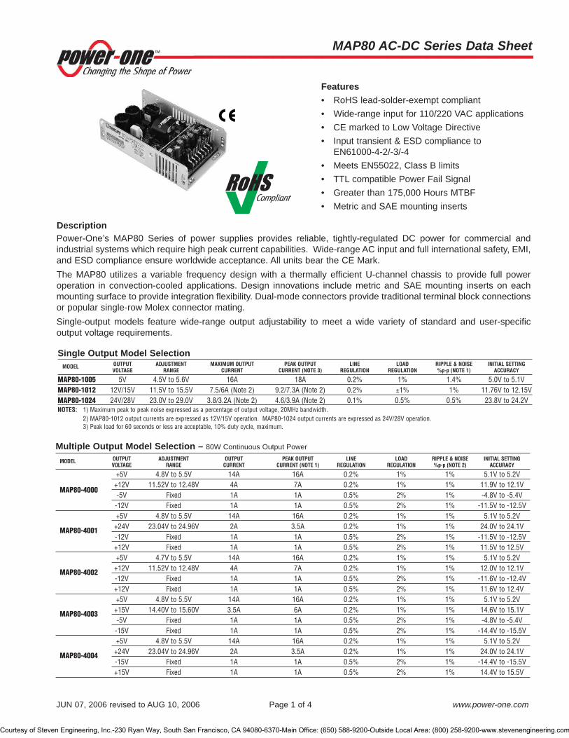
Features• RoHS lead-solder-exempt compliant • Wide-range input for 110/220 VAC applications • CE marked to Low Voltage Directive• Input transient & ESD compliance to
EN61000-4-2/-3/-4• Meets EN55022, Class B limits• TTL compatible Power Fail Signal• Greater than 175,000 Hours MTBF• Metric and SAE mounting inserts
Single Output Model SelectionMODEL OUTPUT ADJUSTMENT MAXIMUM OUTPUT PEAK OUTPUT LINE LOAD RIPPLE & NOISE INITIAL SETTING
VOLTAGE RANGE CURRENT CURRENT (NOTE 3) REGULATION REGULATION %p-p (NOTE 1) ACCURACY
MAP80-1005 5V 4.5V to 5.6V 16A 18A 0.2% 1% 1.4% 5.0V to 5.1VMAP80-1012 12V/15V 11.5V to 15.5V 7.5/6A (Note 2) 9.2/7.3A (Note 2) 0.2% ±1% 1% 11.76V to 12.15VMAP80-1024 24V/28V 23.0V to 29.0V 3.8/3.2A (Note 2) 4.6/3.9A (Note 2) 0.1% 0.5% 0.5% 23.8V to 24.2VNOTES: 1) Maximum peak to peak noise expressed as a percentage of output voltage, 20MHz bandwidth.
2) MAP80-1012 output currents are expressed as 12V/15V operation. MAP80-1024 output currents are expressed as 24V/28V operation.3) Peak load for 60 seconds or less are acceptable, 10% duty cycle, maximum.
Multiple Output Model Selection – 80W Continuous Output Power
MODEL OUTPUT ADJUSTMENT OUTPUT PEAK OUTPUT LINE LOAD RIPPLE & NOISE INITIAL SETTINGVOLTAGE RANGE CURRENT CURRENT (NOTE 1) REGULATION REGULATION %p-p (NOTE 2) ACCURACY
+5V 4.8V to 5.5V 14A 16A 0.2% 1% 1% 5.1V to 5.2V
MAP80-4000+12V 11.52V to 12.48V 4A 7A 0.2% 1% 1% 11.9V to 12.1V-5V Fixed 1A 1A 0.5% 2% 1% -4.8V to -5.4V-12V Fixed 1A 1A 0.5% 2% 1% -11.5V to -12.5V+5V 4.8V to 5.5V 14A 16A 0.2% 1% 1% 5.1V to 5.2V
MAP80-4001 +24V 23.04V to 24.96V 2A 3.5A 0.2% 1% 1% 24.0V to 24.1V-12V Fixed 1A 1A 0.5% 2% 1% -11.5V to -12.5V+12V Fixed 1A 1A 0.5% 2% 1% 11.5V to 12.5V+5V 4.7V to 5.5V 14A 16A 0.2% 1% 1% 5.1V to 5.2V
MAP80-4002 +12V 11.52V to 12.48V 4A 7A 0.2% 1% 1% 12.0V to 12.1V-12V Fixed 1A 1A 0.5% 2% 1% -11.6V to -12.4V+12V Fixed 1A 1A 0.5% 2% 1% 11.6V to 12.4V+5V 4.8V to 5.5V 14A 16A 0.2% 1% 1% 5.1V to 5.2V
MAP80-4003 +15V 14.40V to 15.60V 3.5A 6A 0.2% 1% 1% 14.6V to 15.1V-5V Fixed 1A 1A 0.5% 2% 1% -4.8V to -5.4V-15V Fixed 1A 1A 0.5% 2% 1% -14.4V to -15.5V+5V 4.8V to 5.5V 14A 16A 0.2% 1% 1% 5.1V to 5.2V
MAP80-4004 +24V 23.04V to 24.96V 2A 3.5A 0.2% 1% 1% 24.0V to 24.1V-15V Fixed 1A 1A 0.5% 2% 1% -14.4V to -15.5V+15V Fixed 1A 1A 0.5% 2% 1% 14.4V to 15.5V
MAP80 AC-DC Series Data Sheet
JUN 07, 2006 revised to AUG 10, 2006 Page 1 of 4 www.power-one.com
Power-One’s MAP80 Series of power supplies provides reliable, tightly-regulated DC power for commercial andindustrial systems which require high peak current capabilities. Wide-range AC input and full international safety, EMI,and ESD compliance ensure worldwide acceptance. All units bear the CE Mark.The MAP80 utilizes a variable frequency design with a thermally efficient U-channel chassis to provide full poweroperation in convection-cooled applications. Design innovations include metric and SAE mounting inserts on eachmounting surface to provide integration flexibility. Dual-mode connectors provide traditional terminal block connectionsor popular single-row Molex connector mating.Single-output models feature wide-range output adjustability to meet a wide variety of standard and user-specificoutput voltage requirements.
Description
Courtesy of Steven Engineering, Inc.-230 Ryan Way, South San Francisco, CA 94080-6370-Main Office: (650) 588-9200-Outside Local Area: (800) 258-9200-www.stevenengineering.com

Multiple Output Model Selection (Cont.) – 80W Continuous Output Power
MODEL OUTPUT ADJUSTMENT OUTPUT PEAK OUTPUT LINE LOAD RIPPLE & NOISE INITIAL SETTINGVOLTAGE RANGE CURRENT CURRENT (NOTE 1) REGULATION REGULATION %p-p (NOTE 2) ACCURACY
+5V 4.8V to 5.5V 14A 16A 0.2% 1% 1% 5.1V to 5.2V
MAP80-4010+12V 11.52V to 12.48V 4A 7A 0.2% 1% 1% 12.0V to 12.1V-5V Fixed 1A 1A 0.5% 2% 1% -4.8V to -5.4V-12V Fixed 3A 3A 0.5% 2% 1% -11.5V to -12.5V+5V 4.8V to 5.5V 14A 16A 0.2% 1% 1% 5.1V to 5.2V
MAP80-4020+12V 11.52V to 12.48V 4A 7A 0.2% 1% 1% 12.0V to 12.1V-12V Fixed 1A 1A 0.5% 2% 1% -11.5V to -12.5V-5V Fixed 3A 3A 0.5% 2% 1% -4.8V to -5.4V
NOTES: 1) Peak loads up to 90 Watts for 60 seconds or less are acceptable, (10% duty cycle max.). Peak power must not exceed 90 Watts.2) Maximum peak to peak noise expressed as a percentage of output voltage, 20MHz bandwidth.
Input SpecificationsPARAMETER CONDITIONS/DESCRIPTION MIN NOM MAX UNITS
Input Voltage - AC Continuous input range. 90 135 VAC175 264
Input Frequency AC input. 47 63 HzBrown Out Protection Lowest AC input voltage that regulation is maintained with full rated loads. 90 VACHold-up Time Nominal AC input voltage (115VAC), full rated load. 20 mSInput Current 90 VAC (80W load). 2.5 ARMS
110VAC (80W load). 1.8Input Protection Non-user serviceable internally located AC input line fuse.Inrush Surge Current Internally limited by thermistor. Vin = 264VAC (one cycle). 25° C. 45 APK
Operating Frequency Switching frequency of power supply (varies with load). 22 120 kHz
Output SpecificationsPARAMETER CONDITIONS/DESCRIPTION MIN NOM MAX UNITS
Efficiency Full load, 115VAC. Varies with distribution of loads among outputs. 73 75 80 %Minimum Loads MAP80-1012 0.42
MAP80-1024 0.21 AmpsMAP80-1005 and all multiple output models, main channel only. 1.00
Ripple and Noise Full load, 20MHz bandwidth. See Model Selection Chart.Output Power Continuous output power, all multiple output models. 80 Watts
Peak output power (60s maximum, 10% duty cycle), all multiple output models. 90 WattsOvershoot / Undershoot Output voltage overshoot/undershoot at turn-on, V1, V2. 1 %Regulation Varies by output. Total regulation includes: line changes from 90-132 VAC See Model Selection Chart.
or 175-264, changes in load starting at 20% load and changing to 100% load.Transient Response Recovery time, to within 1% of initial set point due to a 50-100% 500 µS
load change, 4% max. deviation. (Main output of multiple output units).Turn-On Delay Time required for initial output voltage stabilization. 1 5 SecTurn-on Rise Time Time required for output voltage to rise from 10% to 90%. 20 mS
Interface Signals and Internal ProtectionPARAMETER CONDITIONS/DESCRIPTION MIN NOM MAX UNITS
Overvoltage Provided on MAP80-1005 and the main output of multiple output units. 5.5 6.8Protection MAP80-1012 17 23 V
MAP80-1024 32 37Overload Protection Fully protected against output overload and short circuit. Automatic recovery upon removal of overload condition.Power Fail TTL compatible logic signal. Time before regulation dropoutWarning (Note 1) due to loss of input power at 110VAC. 4 mSNOTES: 1) Power Fail Warning is not available on MAP80-1024. The MAP80-1012 is an open collector output, capable of sinking 35 mA, maximum.
MAP80 AC-DC Series Data Sheet
JUN 07, 2006 revised to AUG 10, 2006 Page 2 of 4 www.power-one.com
Courtesy of Steven Engineering, Inc.-230 Ryan Way, South San Francisco, CA 94080-6370-Main Office: (650) 588-9200-Outside Local Area: (800) 258-9200-www.stevenengineering.com

Safety, Regulatory, and EMI SpecificationsPARAMETER CONDITIONS/DESCRIPTION MIN NOM MAX UNITS
Agency Approvals UL1950.CSA 22.2 No. 234/950. ApprovedEN60950 (TUV).
Dielectric Withstand Input to output. 2600 VDCVoltageElectromagnetic FCC CFR title 47 part 15 sub-part B - conducted & radiated. BInterference, EN55022 / CISPR 22 conducted. B ClassConducted EN55022 / CISPR 22 radiated. BInput Transient EN61000-4-5 level 3. Line to line 1 kVProtection Line to ground 2Insulation Resistance Input to output. 7 M�
Leakage Current Per EN60950, 264VAC. 500 µA
Environmental SpecificationsPARAMETER CONDITIONS/DESCRIPTION MIN NOM MAX UNITS
Altitude Operating. 10k ASL Ft.Non-operating. 40k ASL Ft.
Operating Temperature Derate linearly above 50°C by 2.5% per °C At 100% load: 0 50 °Cto a maximum temperature of 70°C. At 50% load: 0 70 °C
Storage Temperature -55 85 °C Temperature Coefficient 0°C to 70°C (After 15 minute warm-up). ±0.02 ±0.03 %/°CRelative Humidity Non-condensing. 5 95 %RHShock Operating, peak acceleration. 20 G Vibration Random vibration, 10Hz to 2kHz, 3 axis. 6 GRMS
OptionsDESCRIPTION NOTES SIZE IMPACT
Cover Add ‘C’ suffix to model number or order part number 412-59585-G separately. 7.20" x 4.20" x 2.05"For convection cooled applications, derate output power to 65 watts on all multiple (183.0mm x 107.0mm x 52.0mm)output models and MAP80-1005. Derate MAP80-1012 and MAP80-1024 to 75 watts.
MAP80 AC-DC Series Data Sheet
JUN 07, 2006 revised to AUG 10, 2006 Page 3 of 4 www.power-one.com
Courtesy of Steven Engineering, Inc.-230 Ryan Way, South San Francisco, CA 94080-6370-Main Office: (650) 588-9200-Outside Local Area: (800) 258-9200-www.stevenengineering.com
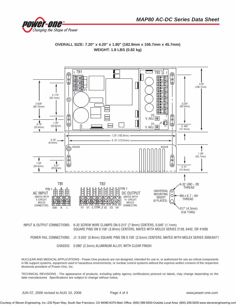
MAP80 AC-DC Series Data Sheet
JUN 07, 2006 revised to AUG 10, 2006 Page 4 of 4 www.power-one.com
OVERALL SIZE: 7.20" x 4.20" x 1.80" (182.9mm x 106.7mm x 45.7mm)WEIGHT: 1.8 LBS (0.82 kg)
INPUT & OUTPUT CONNECTIONS: 6-32 SCREW WIRE CLAMPS ON 0.312" (7.9mm) CENTERS, 0.045" (1.1mm) SQUARE PINS ON 0.156" (3.9mm) CENTERS, MATES WITH MOLEX SERIES 2139, 6442, OR 41695
POWER FAIL CONNECTIONS: J1: 0.035" (0.9mm) SQUARE PINS ON 0.100" (2.5mm) CENTERS, MATES WITH MOLEX SERIES 2695/6471
CHASSIS: 0.090" (2.3mm) ALUMINUM ALLOY, WITH CLEAR FINISH
NUCLEAR AND MEDICAL APPLICATIONS - Power-One products are not designed, intended for use in, or authorized for use as critical componentsin life support systems, equipment used in hazardous environments, or nuclear control systems without the express written consent of the respectivedivisional president of Power-One, Inc.
TECHNICAL REVISIONS - The appearance of products, including safety agency certifications pictured on labels, may change depending on thedate manufactured. Specifications are subject to change without notice.
Courtesy of Steven Engineering, Inc.-230 Ryan Way, South San Francisco, CA 94080-6370-Main Office: (650) 588-9200-Outside Local Area: (800) 258-9200-www.stevenengineering.com

MPU150/MDU150 Series Data Sheet
MCD10009 Rev. 1.0, 15-Oct-07 Page 1 of 6 www.power-one.com
The innovative MPU products incorporate Power Factor Correction (PFC) with a low-profile package designed to meet 1Uheight constraints. The MPU150-4530 and MPU150-4350 provide high current +3.3V and +5V on a single platform to supportmixed-mode, high-speed digital circuitry. Power-One’s unique dual converter architecture combines high reliability withexceptional regulation.All multiple output models feature remote sense on outputs V1 and V2 to provide independent compensation of output cablelosses. Other standard features include independent current sharing on V1 and V2, thermal shutdown, and remote inhibit.Airflow of 300 linear feet per minute (LFM) is required to deliver the full power density of 3.0 watts per cubic inch.The MDU150 Series provides the same benefits as the MPU150 Series, with nominal 48 volt DC input.
Description
Features• RoHS lead free solder and lead solder exempted products
are available• Power Factor Correction (PFC) meets EN61000-3-2• Low-profile height fits 1U constraints• Dual main outputs provide 3.3V and 5V for mixed mode
applications• Single wire current sense on outputs V1 and V2• Remote sense on outputs V1 and V2• Overtemperature, overload, and overvoltage protection• Available with metric or SAE mountings• Greater than 340,000 Hours MTBF• MDU150 models have 48VDC input
Model numbers highlighted in yellow or shaded are not recommended for new designs. See MPU200 for new designs.
AC Input, Single Output Model Selection - 180W WITH 300 LFM FORCED-AIR COOLING
MODEL OUTPUT ADJUSTMENT MAXIMUM OUTPUT LINE LOAD RIPPLE & NOISE INITIAL SETTINGVOLTAGE RANGE CURRENT (NOTE 1) REGULATION REGULATION %p-p (NOTE 2) ACCURACY
MPU150-S259 12V 11.6V to 16V 15A (Note 3) 0.1% 1% 1% 11.97V to 12.03VMPU150-S262 24V 22.8V to 29.2V 7.5A (Note 3) 0.1% 1% 1% 23.95V to 24.05VMPU150-S261 48V 45V to 56V 3.75A (Note 3) 0.1% 1% 1% 47.9V to 48.1V
AC Input, Multiple Output Model Selection - 150W WITH 300 LFM FORCED-AIR COOLINGISOLATED V3 AND V4 CAN BE USED AS POSITIVE OR NEGATIVE OUTPUTS
MODEL OUTPUT ADJUSTMENT OUTPUT LINE LOAD RIPPLE & NOISE INITIAL SETTINGVOLTAGE RANGE CURRENT (NOTE 1) REGULATION REGULATION %Pk-Pk (NOTE 2) ACCURACY
+3.3V 3.15V to 3.80V 35A 0.6% 1.5% 1.5% 3.28V to 3.32VMPU150-3300 +5V 5.0V to 5.5V 20A 0.4% 3% 1% 4.98V to 5.02V
+12V Fixed 2A 0.4% 3% 1% 11.76V to 12.24V+5V 5.0V to 5.5V 17.5A 0.4% 1% 1% 4.98V to 5.02V
MPU150-3524 +12V 10.8V to 13.2V 4A 0.4% 3% 1% 11.94V to 12.06V+24V Fixed 2A 0.4% 3% 1% 23.52V to 24.48V+5V 5.0V to 5.5V 30A (Note 4) 0.4% 1% 1% 4.98V to 5.02V
MPU150-4000 +12V 10.8V to 13.2V 8A 0.4% 1% 1% 11.94V to 12.06V12V 10.8V to 13.2V 3A 0.4% 1% 1% 11.94V to 12.06V5V 5.0V to 5.5V 2A 0.4% 1% 1% 4.98V to 5.02V
+2.5V 2.25V to 3.0V 30A (Note 4) 0.8% 2% 2% 2.49V to 2.51V
MPU150-4230 +3.3V 3.15V to 3.8V 15A (Note 4) 0.6% 1.5% 1.5% 3.28V to 3.32V12V 10.8V to 13.2V 4A (Note 5) 0.4% 1% 1% 11.94V to 12.06V5V 5.0V to 5.5V 2A (Note 5) 0.4% 1% 1% 4.98V to 5.0V
+3.3V 3.15V to 3.80V 30A (Note 4) 0.6% 1.5% 1% 3.28V to 3.32V
MPU150-4350 +5V 5.0V to 5.5V 15A (Note 4) 0.4% 1% 1% 5.00V to 5.04V12V 10.8V to 13.2V 3A (Note 5) 0.4% 7% 1% 11.94V to 12.06V12V 10.8V to 13.2V 3A (Note 5) 0.4% 7% 1% 11.94V to 12.06V+5V 5.0V to 5.5V 30A (Note 4) 0.4% 1% 1% 4.98V to 5.02V
MPU150-4530 +3.3V 3.15V to 3.60V 15A (Note 4) 0.6% 1.5% 1.5% 3.28V to 3.32V12V 10.8V to 13.2V 3A (Note 5) 0.4% 7% 1% 11.94V to 12.06V12V 10.8V to 13.2V 3A (Note 5) 0.4% 7% 1% 11.94V to 12.06V
NOTES: 1) The MPU/MDU150 products require a minimum of 300 LFM of forced-air cooling under 4) Total current between V1 and V2 is 30A, maximum rating.ALL load conditions. It is recommended that the airflow be applied from the input side of the 5) Total current between V3 and V4 is 5A, maximum rating.power supply blowing towards the output.
2) Maximum peak-to-peak noise expressed as a percentage of output voltage, 20 MHz bandwidth.3) Total power of 180 Watts.
Courtesy of Steven Engineering, Inc.-230 Ryan Way, South San Francisco, CA 94080-6370-Main Office: (650) 588-9200-Outside Local Area: (800) 258-9200-www.stevenengineering.com
MPU150/MDU150 Series Data Sheet
MCD10009 Rev. 1.0, 15-Oct-07 Page 2 of 6 www.power-one.com
Ordering Information:OPTIONS SUFFIXES TO ADD TO PART NUMBER
Metric Mounting Add “M” as a suffix to the model number to order chassis with M4 x 0.7 mounting inserts. Metric mounting inserts are standard for single-output models MPU150-S259, MPU150-S261, and MPU150-S262.
RoHS lead solder exemption No RoHS suffix character required.RoHS compliant for all 6 substances Add “G” as the last character of the part number.
DC Input Model Selection - 150W WITH 300 LFM FORCED-AIR COOLINGISOLATED V3 AND V4 CAN BE USED AS POSITIVE OR NEGATIVE OUTPUTS
MODEL OUTPUT ADJUSTMENT OUTPUT LINE LOAD RIPPLE & NOISE INITIAL SETTINGVOLTAGE RANGE CURRENT (NOTE 1) REGULATION REGULATION %Pk-Pk (NOTE 2) ACCURACY
+3.3V 3.15V to 3.80V 35A 0.6% 1.5% 1.5% 3.28V to 3.32VMDU150-3300 +5V 5.0V to 5.5V 20A 0.4% 3% 1% 4.98V to 5.02V
+12V N/A 2A 0.4% 3% 1% 11.76V to 12.24V+5V 5.0V to 5.5V 30A (Note 3) 0.4% 1% 1% 4.98V to 5.02V
MDU150-4000 +12V 10.8V to 13.2V 8A 0.4% 1% 1% 11.94V to 12.06V12V 10.8V to 13.2V 3A 0.4% 1% 1% 11.94V to 12.06V5V 5.0V to 5.5V 2A 0.4% 1% 1% 4.98V to 5.02V
+2.5V 2.25V to 3.0V 30A (Note 3) 2% 2% 2% 2.49V to 2.51V
MDU150-4230 +3.3V 3.15V to 3.8V 15A (Note 3) 1.5% 1.5% 1.5% 3.28V to 3.32V12V 10.8V to 13.2V 3A 1% 1% 1% 11.94V to 12.06V5V 5.0V to 5.5 V 2A 1% 1% 1% 4.98V to 5.0V
+3.3V 3.15V to 3.8V 30A (Note 5) 1.5% 1.5% 1% 3.28V to 3.32V
MDU150-4350 +5V 5.0V to 5.5V 15A (Note 5) 1% 1% 1% 5.00V to 5.04V12V 10.8V to 13.2V 3A (Note 4) 7% 7% 1% 11.94V to 12.06V12V 10.8V to 13.2V 3A (Note 4) 7% 7% 1% 11.94V to 12.06V+5V 5.0V to 5.5V 30A (Note 3) 0.4% 1% 1% 4.98V to 5.02V
MDU150-4530 +3.3V 3.15V to 3.60V 15A (Note 3) 0.6% 1.5% 1.5% 3.28V to 3.32V12V 10.8V to 13.2V 3A (Note 4) 0.4% 7% 1% 11.94V to 12.06V12V 10.8V to 13.2V 3A (Note 4) 0.4% 7% 1% 11.94V to 12.06V
NOTES: 1) The MPU/MDU150 products require a minimum of 300 LFM of forced-air cooling 4) Total current between V3 and V4 is 5A, maximum rating.under ALL load conditions. It is recommended that the airflow be applied from the 5) Total current between V1 and V2 is 40A, maximum ratinginput side of the power supply blowing towards the output.
2) Maximum peak-to-peak noise expressed as a percentage of output voltage, 20 MHz bandwidth.
3) Total current between V1 and V2 is 30A, maximum rating.
MPU150 Input SpecificationsPARAMETER CONDITIONS/DESCRIPTION MIN NOM MAX UNITS
Input Voltage - AC Continuous input range. 85 264 VACInput Frequency AC input. 47 63 HzHold-up Time After last AC line peak at 150 watts. MPU150-4350 17.5 ms
All other models 20 Input Current 85 VAC at full rated load. MPU150 3.0 ARMS
Input Protection Non-user serviceable internally located AC input line fuse. Inrush Surge Current Internally limited by thermistor. Vin = 230 VAC, one cycle, 25°C. 35 APK
Power Factor Per EN61000-3-2. 0.95 W/VAOperating Frequency Switching frequency of main output transformer. 100 120
Switching frequency of secondary transformer. 65 90 kHzSwitching frequency of Power Factor Correction circuit. 60
Courtesy of Steven Engineering, Inc.-230 Ryan Way, South San Francisco, CA 94080-6370-Main Office: (650) 588-9200-Outside Local Area: (800) 258-9200-www.stevenengineering.com

MDU150 Input SpecificationsPARAMETER CONDITIONS/DESCRIPTION MIN NOM MAX UNITS
Input Voltage - DC Continuous input range. 36 75 VDCBrown Out Protection Lowest DC input voltage that regulation is maintained with full rated loads. 34 VDCHold-up Time At 150 watts, over DC input range. 20 msInput Current 36 VDC at full rated load. 6.4 ARMS
Input Protection Non-user serviceable internally located AC input line fuse.Operating Frequency Switching frequency of main output transformer. 100 kHz
Switching frequency of secondary transformer. 70Inrush Current Consult factory.
Output SpecificationsPARAMETER CONDITIONS/DESCRIPTION MIN NOM MAX UNITS
Efficiency Full Rated Load, 110 VAC. Varies with distribution of loads among outputs. 65 75 %Minimum Load, V1 Minimum load required to maintain regulation on, Triple output models V1 4
AV2 at maximum load. Quad output models V1 3Minimum load required on single output models. Single output models V1 0
Minimum Load, V3 Minimum load required to maintain regulation on Quad output models V3 0.3 AV4 at maximum load. Triple output models V3 0
Ripple and Noise Full load, 20 MHz bandwidth. See Model Selection ChartsOutput Power With 300 LFM forced air cooling. (Note 1) 150 WattsOvershoot / Undershoot Output voltage overshoot/undershoot at turn-on. 0 3 5 %Regulation Varies by output. Total regulation includes: line changes over the specified. See Model Selection Charts
input range, changes in load starting at 20% load and changing to 100% load. Transient Response Recovery time, to within 1% of initial set point due to a 50-100% load change, 500 µs
5% max. deviation. Turn-on Delay Time required for initial output voltage stabilization. 2 sTurn-on Rise Time Time required for output voltage to rise from 10% to 90%. 50 msNOTES: 1) This product is not rated for convection applications.
Interface Signals and Internal ProtectionPARAMETER CONDITIONS/DESCRIPTION MIN NOM MAX UNITS
Overvoltage Protection Latch style overvoltage protection. Available on 2.5V output, V1 3.0 3.25V1, V2, all models, and V3 on all models except 3.3V output, V1 4.1 4.65MPU150-3300. 3.3V output, V2 3.8 4.2
5V output, V1, V2 6.0 6.412V output, V2 14 16 V12V output, V3 14 19
MPU150-4350G 3.3V output, V1 4.3 4.65MPU150-S259 V1 17.0 20.5MPU150-S262 V1 32.0 38.0MPU150-S261 V1 58.0 62.7
Overload Protection Fully protected against output overload and short circuit. Automatic recovery upon removal of overload condition. Overtemperature Protection System shutdown due to excessive internal temperature, automatic reset. Output Good Signal, TTL compatible signal available for V1. Pull-up resistor is 10k�. Signal 3.3V 3.16 3.25Low to High Transition is high when output is above the specified limits. Signal shall remain low 5V 4.75 4.90
for 20 milliseconds following loss of Output Good. MPU150-S259 12V 10.5 11.9 VMPU150-S262 24V 21.5 23.5MPU150-S261 48V 43.0 47.0
Input Power Fail Warning TTL compatible logic signal. Time before regulation dropout due to loss of input 5 mspower. May be used as independent PSOK signal in redundant applications.
Current Share Accuracy of shared current with up to 6 parallel units. Single wire current share 10 %on V1 and V2 with return via -Sense return.
Remote Sense Available on V1 and V2. Total voltage compensation for cable losses with 500 mVrespect to the main output.
Inhibit Output voltage is inhibited by application of an external high (5V) signal.
MPU150/MDU150 Series Data Sheet
MCD10009 Rev. 1.0, 15-Oct-07 Page 3 of 6 www.power-one.com
Courtesy of Steven Engineering, Inc.-230 Ryan Way, South San Francisco, CA 94080-6370-Main Office: (650) 588-9200-Outside Local Area: (800) 258-9200-www.stevenengineering.com

Safety, Regulatory, and EMI SpecificationsPARAMETER CONDITIONS/DESCRIPTION MIN NOM MAX UNITS
Agency Approvals UL1950.CSA 22.2 NO. 234/950. ApprovedEN60950 (TÜV).
Dielectric Withstand Voltage Input to output per EN60950. MPU150 2600 VDCMDU150 1544
Electromagnetic Interference FCC CFR title 47 Part 15 Sub-Part B - Conducted. B ClassEN55022 / CISPR 22 Conducted. B
ESD Susceptibility Per EN61000-4-2, level 4. 8 kVRadiated Susceptibility Per EN61000-4-3, level 3. 10 V/MEFT/Burst Per EN61000-4-4, level 3. ±2 kVInput Transient Protection Per EN61000-4-5, class 3. MPU150: Line to Line 1
kVMPU150: Line to Ground 2MDU150: Line to Line 0.5MDU150: Line to Ground 0.5
Insulation Resistance Input to output. 10 M�
Leakage Current Per EN60950. Dual output MPU150 at 264 VAC 22Single and triple output MPU150 at 264 VAC 1.7 mA
MDU150 at 72 VDC (Not required by EN60950)
Environmental SpecificationsPARAMETER CONDITIONS/DESCRIPTION MIN NOM MAX UNITS
Altitude Operating. 10k ASL Ft.Non-Operating. 40k ASL Ft.
Operating Temperature At 100% load 0 50 °CDerate linearly above 50°C by 2.5% per °C. At 50% load 0 70 °C
Storage Temperature -55 85 °CTemperature Coefficient 0°C to 70°C (after 15 minute warm-up). ±0.02 ±0.05 %/°CRelative Humidity Non-Condensing. 5 95 %RHShock Peak acceleration. 20 GPK
Vibration Random vibration, 10Hz to 2kHz, 3 axis. 6 GRMS
OptionsDESCRIPTION NOTES SIZE IMPACT
Metric Mounting Add “M” as a suffix to the model number to order chassis with 8.00" x 4.20" x 1.50"M4 x 0.7 mounting inserts. Metric mounting inserts are standard for (203.2mm x 106.7mm x 38.1mm)single-output models MPU150-S259, MPU150-S261, and MPU150-S262.
MPU150/MDU150 Series Data Sheet
MCD10009 Rev. 1.0, 15-Oct-07 Page 4 of 6 www.power-one.com
NUCLEAR AND MEDICAL APPLICATIONS - Power-One products are not designed, intended for use in, or authorized for use as critical componentsin life support systems, equipment used in hazardous environments, or nuclear control systems without the express written consent of the respectivedivisional president of Power-One, Inc.
TECHNICAL REVISIONS - The appearance of products, including safety agency certifications pictured on labels, may change depending on the datemanufactured. Specifications are subject to change without notice.
Courtesy of Steven Engineering, Inc.-230 Ryan Way, South San Francisco, CA 94080-6370-Main Office: (650) 588-9200-Outside Local Area: (800) 258-9200-www.stevenengineering.com

CHASSIS: 0.063" (1.6mm) ALUMINUM ALLOY,
WITH CLEAR FINISH
Overall Size: 8.00" x 4.20" x 1.50" (203.2mm x 106.7mm x 38.1mm) Weight: 1.8 lb (0.82 kg)
(4PL)CONNECTIONS8-32 SCREW
OUTPUTS:
INPUTS
ADJ.V1,V.
N
L
+V1
J1
RTN
PINS SERIES 5263, P/N: 80-70-1040 (LOOSE)HOUSING SERIES 5264-N, P/N: 50-37-5103 (&)MATES WITH MOLEX:
ON 2.50mm CENTERS. MOLEX SERIES 5268-NA, P/N: 22-05-7105, PINS
1. SIGNAL GROUND
2. INHIBIT3. POWER FAIL WARNING
4. OUTPUT GOOD, V15. NO CONNECTION
6. NO CONNECTION
7. NO CONNECTION8. CURRENT SHARE, V1
9. -S, V110. +S, V1
PIN
INTERFACE CONNECTIONS (J300)
SINGLE OUTPUT
M4 X 0.7, 8 PLACES. MAXIMUM TORQUE: 3.5 IN/LBS (0.40 N/M)
NOTE:MAX. LEAD PROTRUSION IS 0.0625" (1.588mm)ON THE FOUR BOTTOM MOUNTING HOLES.MAX. LEAD PROTRUSION OF 0.25" (6.25mm)IS ACCEPTABLE ON THE FOUR SIDE MOUNTINGHOLES.
CONNECTOR MOLEX HOUSING PIN PINS PINS WIRESERIES SERIES (LOOSE) (CHAIN) GAUGE41695 09-50-8051 6838 08-50-0189 08-50-0187 18-20AWGJ1 41695 09-50-8051 2478 08-50-0106 08-50-0105 18-20AWG(ALL MODELS) 2139 09-50-3051 2478 08-50-0106 08-50-0105 18-20AWG
J300 5264-N 50-37-5103 5263 08-70-1040 08-70-1039 22-28AWG
MPU150/MDU150 Series Data Sheet
MCD10009 Rev. 1.0, 15-Oct-07 Page 5 of 6 www.power-one.com
Courtesy of Steven Engineering, Inc.-230 Ryan Way, South San Francisco, CA 94080-6370-Main Office: (650) 588-9200-Outside Local Area: (800) 258-9200-www.stevenengineering.com

CONNECTOR MOLEX HOUSING PIN PINS PINS WIRESERIES SERIES (LOOSE) (CHAIN) GAUGE41695 09-50-8051 6838 08-50-0189 08-50-0187 18-20AWGJ1 41695 09-50-8051 2478 08-50-0106 08-50-0105 18-20AWG(ALL MODELS) 2139 09-50-3051 2478 08-50-0106 08-50-0105 18-20AWG
J2 5051-N 22-01-1022 2759 08-50-0114 08-50-0113 22-30AWG(TRIPLE OUTPUT) 5051-N 22-01-1022 2759 08-65-0805 08-65-0804 22-30AWG
41695 09-50-8021 6838 08-50-0189 08-50-0187 18-20AWGJ3 41695 09-50-8021 2478 08-50-0106 08-50-0105 18-20AWG(TRIPLE OUTPUT) 2139 09-50-3021 2478 08-50-0106 08-50-0105 18-20AWG41695 09-50-8061 6838 08-50-0189 08-50-0187 18-20AWGJ3 41695 09-50-8061 2478 08-50-0106 08-50-0105 18-20AWG(QUAD OUTPUT) 2139 09-50-3061 2478 08-50-0106 08-50-0105 18-20AWG
J300 5264-N 50-37-5103 5263 08-70-1040 08-70-1039 22-28AWG
Overall Size: 8.00" x 4.20" x 1.50" (203.2mm x 106.7mm x 38.1mm) Weight: 2.0 lb (0.89 kg)
NOTE:MAX. LEAD PROTRUSION IS 0.0625" (1.588mm)ON THE FOUR BOTTOM MOUNTING HOLES.MAX. LEAD PROTRUSION OF 0.25" (6.25mm)IS ACCEPTABLE ON THE FOUR SIDE MOUNTINGHOLES.
CHASSIS: 0.063" (1.6mm) ALUMINUM ALLOY,
WITH CLEAR FINISH
MPU150/MDU150 Series Data Sheet
MCD10009 Rev. 1.0, 15-Oct-07 Page 6 of 6 www.power-one.com
Courtesy of Steven Engineering, Inc.-230 Ryan Way, South San Francisco, CA 94080-6370-Main Office: (650) 588-9200-Outside Local Area: (800) 258-9200-www.stevenengineering.com

AC Input, Single-Output Model Selection 200W/225W PK WITH 300 LFM FORCED-AIR COOLING (NOTE 1)
MODEL OUTPUT ADJUSTMENT MAXIMUM OUTPUT PEAK OUTPUT LINE LOAD RIPPLE & NOISE INITIAL SETTINGVOLTAGE RANGE CURRENT (NOTE 2) CURRENT (NOTE 2) REGULATION REGULATION %p-p (NOTE 3) ACCURACY
MPU200-1012 12V 11.6V to 16V 17.0A 19.0A 0.1% 1% 1% 11.97V to 12.03VMPU200-1024 24V 22.8V to 29.2V 8.35A 9.4A 0.1% 1% 1% 23.95V to 24.05VMPU200-1048 48V 45V to 56V 4.2A 4.7A 0.1% 1% 1% 47.9V to 48.1V
AC Input, Multiple-Output Model Selection 200W WITH 300 LFM FORCED-AIR COOLING (NOTE 1)
ISOLATED V3 AND V4 CAN BE USED AS POSITIVE OR NEGATIVE OUTPUTS
MODEL OUTPUT ADJUSTMENT MAXIMUM OUTPUT LINE LOAD RIPPLE & NOISE INITIAL SETTINGVOLTAGE RANGE CURRENT (NOTE 2) REGULATION REGULATION %Pk-Pk (NOTE 3) ACCURACY
+5V 5.0V to 5.5V 30A (Note 4) 0.4% 1% 1% 4.98V to 5.02V
MPU200-4530 +3.3V 3.15V to 3.60V 15A (Note 4) 0.6% 1.5% 1.5% 3.28V to 3.32V12V 10.8V to 13.2V 8A (Note 5) 0.4% 10% 1% 11.94V to 12.06V12V 10.8V to 13.2V 4A (Note 5) 0.4% 10% 1% 11.60V to 12.40V
NOTES: 1) This product is not rated for convection applications.2) The MPU/MDU150 products require a minimum of 300 LFM of forced-air cooling under ALL load conditions. It is recommended that the airflow be
applied from the input side of the power supply blowing towards the output.3) Maximum peak-to-peak noise expressed as a percentage of output voltage, 20 MHz bandwidth.4) Total current for V1 and V2 is not to exceed 35A.5) Total power on V3 and V4 is not to exceed 100W.
Features• RoHS lead free solder and lead solder exempted products
are available• Power Factor Correction (PFC) meets EN61000-3-2• Same size, airflow, and construction as MPU150/MDU150
with over 33% more power• Single-wire current sense on quad model outputs V1 and V2• Remote sense on quad model outputs V1 and V2• Current share and N+1 redundancy (standard on all models)• Overtemperature, overload, and overvoltage protection• Available with SAE mountings• MDU200 models have 48VDC input
MPU200/MDU200 Series Data Sheet
MCD10010 Rev. 1.0 Page 1 of 6 www.power-one.com
The MPU200/MDU200 Series is based upon the proven architecture of the MPU150/MDU150 product line. The MPU productsincorporate Power Factor Correction (PFC) with a low-profile package designed to meet 1U height constraints. In this series, 200Wof continuous output power is provided with single or multiple output units suited for distributed power or central power applications.The series provides high current +3.3V and +5V on a single platform to support mixed-mode, high-speed digital circuitry.Power-One's dual-converter architecture combines high reliability with exceptional regulation. All multiple-output models featureremote sense on outputs V1 and V2 to provide independent compensation of output cable losses.Other standard features include independent current sharing on V1 and V2 quad-model outputs, thermal shutdown, and remoteinhibit. Airflow of 300 linear feet per minute (LFM) is required to deliver the full power density of greater than 4.0 watts per cubic inch.The MDU200 Series provides the same benefits as the MPU200 Series, with a nominal 48 volt DC input.
Description
Ordering Information:OPTIONS SUFFIXES TO ADD TO PART NUMBER
Metric Mounting Add “M” as a suffix to the model number to order chassis withM3 x 0.7 mounting inserts. Consult factory for availability.
Isolation Diode Offered on single-output models. Add “D” to the part number suffix if an isolation diode is needed.Consult factory for availability.
RoHS lead solder exemption No RoHS suffix character required.RoHS compliant for all 6 substances Add “G” as the last character of the part number.
Courtesy of Steven Engineering, Inc.-230 Ryan Way, South San Francisco, CA 94080-6370-Main Office: (650) 588-9200-Outside Local Area: (800) 258-9200-www.stevenengineering.com

DC Input, Single Output Model Selection 200W WITH 300 LFM FORCED-AIR COOLING (NOTE 1)
MODEL OUTPUT ADJUSTMENT MAXIMUM OUTPUT PEAK OUTPUT LINE LOAD RIPPLE & NOISE INITIAL SETTINGVOLTAGE RANGE CURRENT (NOTE 2) CURRENT (NOTE 2) REGULATION REGULATION %Pk-Pk (NOTE 3) ACCURACY
MDU200-1012G 12V 11.6V to 16V 17.0A 19.0A 0.1% 1% 1% 11.97V to 12.03VMDU200-1024G 24V 22.8V to 29.2V 8.35A 9.4A 0.1% 1% 1% 23.95V to 24.05V(NOTE 4)MDU200-1048G 48V 45V to 56V 4.2A 4.7A 0.1% 1% 1% 47.9V to 48.1VIsolation Diode Option - Offered on single-output models. Add “D” at the end of the part number if an isolation diode is needed.
MPU200 Input SpecificationsPARAMETER CONDITIONS/DESCRIPTION MIN NOM MAX UNITSInput Voltage - AC Continuous input range. 85 264 VACInput Frequency AC input. 47 63 HzHold-up Time After last AC line peak at 200 watts 15 msInput Current 85 VAC at full rated load. 4.0 ARMSInput Protection Non-user serviceable internally located AC input line fuse. Inrush Surge Current Internally limited by thermistor. Vin = 230 VAC, one cycle, 25°C. 35 APKPower Factor Per EN61000-3-2. 0.95 W/VAOperating Frequency Switching frequency of main output transformer. 100 120
Switching frequency of secondary transformer. 65 90 kHzSwitching frequency of Power Factor Correction circuit. 60
MDU200 Input SpecificationsPARAMETER CONDITIONS/DESCRIPTION MIN NOM MAX UNITSInput Voltage - DC Continuous input range. 36 75 VDCBrown Out Protection Lowest DC input voltage that regulation is maintained with full rated loads. 34 VDCHold-up Time At 200 watts, over DC input range. 15 msInput Current 36 VDC at full rated load. 8.35 ARMSInput Protection Non-user serviceable internally located AC input line fuse.Inrush Surge Current Consult factory.Operating Frequency Switching frequency of main output transformer. 100 kHz
Switching frequency of secondary transformer. 70
MPU200/MDU200 Series Data Sheet
MCD10010 Rev. 1.0 Page 2 of 6 www.power-one.com
NOTES:1) This product is not rated for convection applications.2) The MPU/MDU150 products require a minimum of 300 LFM of forced-air cooling under ALL load conditions. It is recommended that the airflow be
applied from the input side of the power supply blowing towards the output.3) Maximum peak-to-peak noise expressed as a percentage of output voltage, 20 MHz bandwidth.4) Derating is required on output voltages above 27VDC. Consult factory.
Courtesy of Steven Engineering, Inc.-230 Ryan Way, South San Francisco, CA 94080-6370-Main Office: (650) 588-9200-Outside Local Area: (800) 258-9200-www.stevenengineering.com

Output SpecificationsPARAMETER CONDITIONS/DESCRIPTION MIN NOM MAX UNITSEfficiency Full Rated Load, 110 VAC (MPU) or 48VDC (MDU).
Varies with distribution of loads among outputs. 65 75 %Minimum Load, V1 Minimum load required to maintain regulation on,
V2 at maximum load. Quad output model V1 3 AMinimum load required on single output models. Single output models V1 0Minimum Load, V3 Minimum load required to maintain regulation on Quad output model V3 0.3 A
V4 at maximum load.Ripple and Noise Full load, 20 MHz bandwidth. See Model Selection ChartsOvershoot / Undershoot Output voltage overshoot/undershoot at turn-on. 5 %Regulation Varies by output. Total regulation includes: line changes over the specified. See Model Selection Charts
input range, changes in load starting at 20% load and changing to 100% load. Transient Response Recovery time, to within 1% of initial set point due to a 50-100% load change, 500 μs
5% max. deviation. Turn-on Delay Time required for initial output voltage stabilization. 2 sTurn-on Rise Time Time required for output voltage to rise from 10% to 90%. MPU200 50 ms
MDU200 80
Interface Signals and Internal ProtectionPARAMETER CONDITIONS/DESCRIPTION MIN NOM MAX UNITSOvervoltage Protection Latch style overvoltage protection.
MPU200-4530 3.3V output 3.8 4.2MPU200-4530 5V output 6.0 6.4MPU200-4530 12V output 14 19 VMDU200/MPU200-1012 V1 17.0 20.5MDU200/MPU200-1024 V1 32.0 38.0MDU200/MPU200-1048 V1 58.0 62.7
Overload Protection Fully protected against output overload and short circuit. Automatic recovery upon removal of overload condition. Overtemperature Protection System shutdown due to excessive internal temperature, automatic reset. Output Good Signal TTL compatible signal available for V1. Internal pull-up resistor is 475�. 3.3V 3.16 3.25
(Transision from Signal is high when output is above the specified limits. Signal shall 5V 4.75 4.95Low to High) remain low for 20 milliseconds following loss of Output Good. V
MDU200/MPU200-1012 12V 10.5 11.9MDU200/MPU200-1024 24V 21.5 23.5MDU200/MPU200-1048 48V 43.0 47.0
Input Power Fail Warning TTL compatible logic signal. Time before regulation dropout due to loss of input 5 mspower. May be used as independent PSOK signal in redundant applications.
Current Share Accuracy of shared current with up to 6 parallel units. Single wire current share 10 %on V1 and V2 with return via -Sense return.
Remote Sense Available on V1 and V2. Total voltage compensation for cable losses with 500 mVrespect to the main output.
Inhibit Output voltage is inhibited by application of an external high (5V) signal.
MPU200/MDU200 Series Data Sheet
MCD10010 Rev. 1.0 Page 3 of 6 www.power-one.com
Courtesy of Steven Engineering, Inc.-230 Ryan Way, South San Francisco, CA 94080-6370-Main Office: (650) 588-9200-Outside Local Area: (800) 258-9200-www.stevenengineering.com
Safety, Regulatory, and EMI SpecificationsPARAMETER CONDITIONS/DESCRIPTION MIN NOM MAX UNITSAgency Approvals UL60950,CSA 22.2 NO. 60950, and EN60950-1 (TÜV). (Approved)Dielectric Withstand Voltage Input to output per EN60950. MPU200 2600 VDC
MDU200 1414 Electromagnetic Interference FCC CFR title 47 Part 15 Sub-Part B - Conducted. B Class
EN55022 / CISPR 22 Conducted. BESD Susceptibility Per EN61000-4-2, level 4. 8 kVRadiated Susceptibility Per EN61000-4-3, level 3. 10 V/MEFT/Burst Per EN61000-4-4, level 3. ±2 kVInput Transient Protection Per EN61000-4-5, class 3. MPU200: Line to Line 1
kVMPU200: Line to Ground 2MDU200: Line to Line 0.5MDU200: Line to Ground 0.5
Insulation Resistance Input to output. 10 MVLeakage Current Per EN60950. MPU200 Quad Output Model 2.2 mA
MPU200 Single Output Models 1.7MDU200 at 72 VDC (Not required by EN60950) N/A
Environmental SpecificationsPARAMETER CONDITIONS/DESCRIPTION MIN NOM MAX UNITSAltitude Operating. 10k ASL Ft.
Non-Operating. 40k ASL Ft.Operating Temperature At 100% load 0 50 °C
Derate linearly above 50°C by 2.5% per °C. At 50% load 0 70 °CStorage Temperature -55 85 °CTemperature Coefficient 0°C to 70°C (after 15 minute warm-up). ±0.02 ±0.05 %/°CRelative Humidity Non-Condensing. 5 95 %RHShock Peak acceleration. 20 GPK
Vibration Random vibration, 10Hz to 2kHz, 3 axis. 6 GRMS
OptionsDESCRIPTION NOTESMetric Mounting Add “M” as a suffix to the model number to order chassis with
M3 x 0.7 mounting inserts. Consult factory for availability.Isolation Diode Offered on single-output models. Add “D” to the part number suffix if an isolation diode is needed. Consult factory for
availability.
MPU200/MDU200 Series Data Sheet
MCD10010 Rev. 1.0 Page 4 of 6 www.power-one.com
Courtesy of Steven Engineering, Inc.-230 Ryan Way, South San Francisco, CA 94080-6370-Main Office: (650) 588-9200-Outside Local Area: (800) 258-9200-www.stevenengineering.com

CONNECTOR MOLEX HOUSING PIN PINS PINS WIRESERIES SERIES (LOOSE) (CHAIN) GAUGE41695 09-50-8051 6838 08-50-0189 08-50-0187 18-20AWG
J1 41695 09-50-8051 2478 08-50-0106 08-50-0105 18-20AWG2139 09-50-3051 2478 08-50-0106 08-50-0105 18-20AWG
J300 5264-N 50-37-5103 5263 08-70-1040 08-70-1039 22-28AWG
CHASSIS: 0.063" (1.6mm) ALUMINUM ALLOY,WITH CLEAR FINISH
Overall Size: 8.00" x 4.20" x 1.50" (203.2mm x 106.7mm x 38.1mm) Weight: 2.0 lb (0.89 kg)
(4PL)CONNECTIONS8-32 SCREW
OUTPUTS:
SADJ.V1,V.
+V1
J1
J1
RTN
PINS SERIES 5263, P/N: 80-70-1040 (LOOSE)HOUSING SERIES 5264-N, P/N: 50-37-5103 (&)MATES WITH MOLEX:
ON 2.50mm CENTERS. MOLEX SERIES 5268-NA, P/N: 22-05-7105, PINS
1. SIGNAL GROUND
2. INHIBIT3. POWER FAIL WARNING
4. OUTPUT GOOD, V15. NO CONNECTION
6. NO CONNECTION
7. NO CONNECTION8. CURRENT SHARE, V1
9. -S, V110. +S, V1
PIN
INTERFACE CONNECTIONS (J300)
SINGLE OUTPUT
INPUT
MDU200DC
++
1
2
3
4
5
MPU200ACINPUT
1L
N 3
5
NOTE:MAX. LEAD PROTRUSION IS 0.0625" (1.588mm)ON THE FOUR BOTTOM MOUNTING HOLES.MAX. LEAD PROTRUSION OF 0.25" (6.25mm)IS ACCEPTABLE ON THE FOUR SIDE MOUNTINGHOLES.
3 TBD
MPU200/MDU200 Series Data Sheet
MCD10010 Rev. 1.0 Page 5 of 6 www.power-one.com
Courtesy of Steven Engineering, Inc.-230 Ryan Way, South San Francisco, CA 94080-6370-Main Office: (650) 588-9200-Outside Local Area: (800) 258-9200-www.stevenengineering.com

MPU200/MDU200 Series Data Sheet
MCD10010 Rev. 1.0 Page 6 of 6 www.power-one.com
CONNECTOR MOLEX HOUSING PIN PINS PINS WIRESERIES SERIES (LOOSE) (CHAIN) GAUGE41695 09-50-8051 6838 08-50-0189 08-50-0187 18-20AWGJ1 41695 09-50-8051 2478 08-50-0106 08-50-0105 18-20AWG(ALL MODELS) 2139 09-50-3051 2478 08-50-0106 08-50-0105 18-20AWG
J2 5051-N 22-01-1022 2759 08-50-0114 08-50-0113 22-30AWG(TRIPLE OUTPUT) 5051-N 22-01-1022 2759 08-65-0805 08-65-0804 22-30AWG
41695 09-50-8021 6838 08-50-0189 08-50-0187 18-20AWGJ3 41695 09-50-8021 2478 08-50-0106 08-50-0105 18-20AWG(TRIPLE OUTPUT) 2139 09-50-3021 2478 08-50-0106 08-50-0105 18-20AWG41695 09-50-8061 6838 08-50-0189 08-50-0187 18-20AWGJ3 41695 09-50-8061 2478 08-50-0106 08-50-0105 18-20AWG(QUAD OUTPUT) 2139 09-50-3061 2478 08-50-0106 08-50-0105 18-20AWG
J300 5264-N 50-37-5103 5263 08-70-1040 08-70-1039 22-28AWG
Overall Size: 8.00" x 4.20" x 1.50" (203.2mm x 106.7mm x 38.1mm) Weight: 2.0 lb (0.89 kg)
NOTE:MAX. LEAD PROTRUSION IS 0.0625" (1.588mm)ON THE FOUR BOTTOM MOUNTING HOLES.MAX. LEAD PROTRUSION OF 0.25" (6.25mm)IS ACCEPTABLE ON THE FOUR SIDE MOUNTINGHOLES.
3 TBD
CHASSIS: 0.063" (1.6mm) ALUMINUM ALLOY,WITH CLEAR FINISH
NUCLEAR AND MEDICAL APPLICATIONS - Power-One products are not designed, intended for use in, or authorized for use as critical componentsin life support systems, equipment used in hazardous environments, or nuclear control systems without the express written consent of the respectivedivisional president of Power-One, Inc.
TECHNICAL REVISIONS - The appearance of products, including safety agency certifications pictured on labels, may change depending on thedate manufactured. Specifications are subject to change without notice.
Courtesy of Steven Engineering, Inc.-230 Ryan Way, South San Francisco, CA 94080-6370-Main Office: (650) 588-9200-Outside Local Area: (800) 258-9200-www.stevenengineering.com

MCD10029 Rev. 1.0 Page 1 of 3 www.power-one.com
MM5 and MM5-MED Modular Products Data Sheet
Not Recommended For New Designs
MM5 and MM5-MED Features • EN60601-1, UL2601-1, IEC601-1 approved • Class B conducted emissions • Low leakage current <300 mA • Modular design with current sharing on all outputs • Industry leading 8.7W/Cu.inch power density • High Efficiency— 80-87% at full load • High output current capacity from a single slot—60A • 900/1200W output power • Compact package—2.5” x 5” x 11” • 1 to 5 outputs with 1V to 60V standard output voltages • Isolated 5V @ 2A stand-by voltage • Series and parallel capability • EN61000 immunity standards compliant • Remote sense on all outputs with ratings of 10A or greater • Global and individual module inhibit/enable • Configurable to Customers requirements.
Description The MM5 Series modular power supplies offer fully enclosed power solutions that optimize flexibility and space allocation through common modular assemblies. The MED option provides approvals to EN60601-1, UL2601-1 and IEC601-1. These products meet Class B conducted emissions with <300 mA low leakage current. An extensive array of interface signals make these power supplies ideally suited for meeting today’s complex power requirements in a wide variety of applications. The MM5 Series can provide up to 1200W output power.
Courtesy of Steven Engineering, Inc.-230 Ryan Way, South San Francisco, CA 94080-6370-Main Office: (650) 588-9200-Outside Local Area: (800) 258-9200-www.stevenengineering.com

MCD10029 Rev. 1.0 Page 2 of 3 www.power-one.com
MM5 and MM5-MED Modular Products Data Sheet
Single Output Module Current Ratings, 300 Watt Single Slot Vout 2 3.3 5 12 15 24 28 36 48 60 Amps 60 60 60 25 20 12.5 11 9 6 5
Input Specifications Input voltage range: 85 to 264 Vac, 47 to 63 Hz Power Factor: 0.99 at full load and nominal line Inrush Current: 40 A peak hot and cold start Input Protection: AC line fuse provided Signals and Controls LED Indicators: Front panel green LED indicates AC-OK Front panel green LED indicates FAN-OK Module green LED indicates DC-OK DC - OK Signal: TTL compatible signal, normally low. Goes high when power supply is 5-8% over nominal. See Options AC – OK Signal: TTL compatible signal, normally low. Goes high when input voltage is bellow nominal. Module Enable: Normally TTL High or Open, drive low to Disable. See Options Fan Fail: TTL compatible signal, normally low. Goes high when fan fails. Hold-Up Time: 20 ms minimum at full load, 90-264 Vac Margining/Remote Voltage Adjustment: –10% to +10% of nominal. Safety & Environmental Operating Temperature: 0 to 50ºC Storage Temperature: -40ºC to +85ºC Operating Humidity: Maximum 95% non-condensing Operating Altitude: 10,000 feet Non-operating Altitude: 40,000 feet Temperature Coefficient: 0.01% per �C within rated load Safety Agency Compliance: cTUVus, UL60950-1:2003, CAN/CSA-C22.2 No. 60950-1-03, TUV, EN60950, CB Report, UL2601-1, IEC60601-1, EN60601-1, CE EMI (conducted): Meets CISPR22, EN55022, Class B Immunity: Meets EN61000 sections 3-2, 3-3, 4-2, 4-3, 4-4, 4-5, 4-6, and 4-11 AC Leakage Current: 2.0 mA max. @ 250 Vac, 50 Hz. AC Low Leakage: 0.300 mA max. @ 250 Vac, 50 Hz
Output Specifications Output Power: 900 W maximum at 90–264 Vac, 1200 W maximum at 180-264Vac Overshoot/Undershoot: Less than 1% at turn on or turn off. Less than 2% load step. Start-Up Time: Less than 1 second with Ac power on to regulated outputs @ full load Efficiency: 82-87% measured at 230 Vac, full load 80-85% measured at 115 Vac, full load Load Regulation: .05% typical, .2% maximum, 0-100% load, 90–264 Vac Line Regulation: .05% typical Cross Regulation: Less than 0.5% Minimum Load: Minimum loading not required Over-temperature Protection: Automatic restart Remote Sense: Compensates for voltage drop of up to 0.5 V to the load. Over-voltage Protection: All outputs set at 120-130% of nominal. Recycle power to restart. Output Noise and Ripple: 50 mV or 1% pk-pk maximum on all outputs measured at 20 MHz bandwidth Voltage Adjustment: -10% to +10% of nominal Long Term Drift: .02% of nominal per thousand hours Current Limit: All outputs set at 105-130% of nominal. Automatic recovery. Current Share: 5% typical, 10% maximum at 20-100% of full load Reverse Voltage Protection: 100% of nominal Stand-By Output: 5V @ 2.0A present whenever AC input is applied. Mechanical Specifications Size: 2.5” x 5.0” x 11.0” I/O Connector: See drawings for details AC Connector: Tyco 282966-3; mating-Tyco 284043-3. MTBF: 300K hours calculated at 25°C, Bellcore Standard Warranty: Two years from date of shipment, standard product only.
Specifications are subject to change without prior notice.
NUCLEAR AND MEDICAL APPLICATIONS - Power-One products are not designed, intended for use in, or authorized for use as critical components in life support systems, equipment used in hazardous environments, or nuclear control systems without the express written consent of the respective divisional president of Power-One, Inc.
TECHNICAL REVISIONS - The appearance of products, including safety agency certifications pictured on labels, may change depending on the date manufactured. Specifications are subject to change without notice.
Courtesy of Steven Engineering, Inc.-230 Ryan Way, South San Francisco, CA 94080-6370-Main Office: (650) 588-9200-Outside Local Area: (800) 258-9200-www.stevenengineering.com

MCD10029 Rev. 1.0 Page 3 of 3 www.power-one.com
MM5 and MM5-MED Modular Products Data Sheet
Output Module – Single Output – Single Slot
J3 Pin Function 1 NC 2 NC 3 MARGIN/REMOTE VOLTAGE ADJ 4 DC – OK LOW 5 CURRENT SHARE 6 DC - OK HIGH 7 -SENSE 8 ENABLE LOW 9 +SENSE 10 ENABLE HIGH
CONNECTORS: JST P/N S-10B-PADSS-1 MATING: JST P/N PADP-10V-1-S WITH CONTACTS P/N SPH-001T-P0.5L
J7
Pin Function 1 FAN FAIL 2 AC - OK 3 5V STANDBY 4 5V STANDBY 5 RETURN 6 RETURN
CONNECTORS: JST P/N S06B-PASK-2 MATING: JST P/N PAP-06V-S WITH CONTACTS P/N SPHD-001T-P0.5
Outline Drawings and Dimensions
Courtesy of Steven Engineering, Inc.-230 Ryan Way, South San Francisco, CA 94080-6370-Main Office: (650) 588-9200-Outside Local Area: (800) 258-9200-www.stevenengineering.com

High Power Modular Products Data Sheet
AUG 10, 2005 revised to AUG 17, 2006 Page 1 of 19 www.power-one.com
Table of ContentsProduct Overview . . . . . . . . . . . . . . . . . . . . . . . . . . .2
Modular System Overview and Selection . . . . . . . . .4
Configuring a Power System . . . . . . . . . . . . . . . . . . .5
DC Output Module Selection . . . . . . . . . . . . . . . . . . .6
Paralleled Module Configurations . . . . . . . . . . . . . . .8
DC Module Specifications . . . . . . . . . . . . . . . . . . . . .9
Chassis Electrical Specifications . . . . . . . . . . . . . . .11
Exceptional AC Input Transient Immunity . . . . . . . .15
DC Output Modules Demonstrated MTBF . . . . . . .17
DescriptionPower-One’s high power modular products can beconfigured to provide up to 21 outputs in over 10million voltage and current combinations. Eighteenchassis are available from 1000 to 4000 watts;including power factor corrected, three-phase input,and metric mounting hardware models. Over 90output modules are available to provide voltages from1 to 48VDC. Output modules have a fielddemonstrated MTBF of greater than 5 million hours.Other features include a comprehensive array ofmodule and system interface signals, extensive inputtransient protection, and international regulatoryagency approvals. These high-performance productshave a proven track record in high reliabilitycommunications, semiconductor test, and industrialapplications.
Modular High Power Mechanical Drawings (Thesemay be downloaded from www.power-one.com byusing the drawings link located below the ModularHigh Power data sheet link.)
NUCLEAR AND MEDICAL APPLICATIONS - Power-One products are not designed, intended for use in, or authorized for use as critical componentsin life support systems, equipment used in hazardous environments, or nuclear control systems without the express written consent of the respectivedivisional president of Power-One, Inc.
TECHNICAL REVISIONS - The appearance of products, including safety agency certifications pictured on labels, may change depending on thedate manufactured. Specifications are subject to change without notice.
Courtesy of Steven Engineering, Inc.-230 Ryan Way, South San Francisco, CA 94080-6370-Main Office: (650) 588-9200-Outside Local Area: (800) 258-9200-www.stevenengineering.com

High Power Modular Products Data Sheet
AUG 10, 2005 revised to AUG 17, 2006 Page 2 of 19 www.power-one.com
Modular High Power Series Product Overview
CHASSISMETRIC MOUNTING SMF3 HMF3 HMF5 SMM3 SMM5 HMM5 HMM7 RMF5 RMM5STANDARD SPF3 HPF3 HPF5 SPM3 SPM5 HPM5 HPM7 RPF5 RPM5
OUTPUT POWER AND POWER FACTOR
.99 PFC to meet EN60555 YES YES YES N/A N/A N/A N/A YES N/A
Max output wattage at high range line input 1350 2000 2000 1000 1500 2000 2500 3000 4000
Max output wattage at low range line input* 1000 1500 1500 1000 1500 N/A N/A N/A N/A
INPUT VOLTAGE SPECIFICATIONS**
High range VAC input 160-264 160-264 160-264 175-264 175-264 180-264 180-264 160-264 180-264
Low range VAC input 85-159 85-159 85-159 90-132 90-132 N/A N/A N/A N/A
VAC input selection Wide Range Wide Range Wide Range Manual Manual N/A N/A N/A N/A
VAC input phases Single Single Single Single Single Single Single Single Three
OUTPUT MODULE SPECIFICATIONS
Max # of outputs 9 9 15 9 15 15 21 15 15
# of module slots 3 3 5 3 5 5 7 5 5
MECHANICAL SPECIFICATIONS
Chassis size H x W x L, inches 5 x 5.5 x 12.5 5 x 5.5 x12.5 5 x 8 x 11 5 x 5.5 x 11 5 x 8 x 11 5 x 8 x 11 5 x 11 x 13 5 x 8 x 12.5 5 x 8 x 15
Chassis size H x W, millimeters 127 x 140 127 x 140 127 x 203 127 x 140 127 x 203 127 x 203 127 x 280 127 x 203 127 x 203
Chassis size x L, millimeters x 318 x 318 x 280 x 280 x 280 x 280 x 330 x 318 x 381
INPUT TRANSIENT PROTECTION SPECIFICATIONS
ESD Immunity Level 4 Level 4 Level 4 Level 4 Level 4 Level 4 Level 4 Level 4 Level 4EN61000-4-2, 15kV/8kV 15kV/8kV 15kV/8kV 15kV/8kV 15kV/8kV 15kV/8kV 15kV/8kV 15kV/8kV 15kV/8kV
RF Susceptibility Level 3 Level 3 Level 3 Level 3 Level 3 Level 3 Level 3 Level 3 Level 3EN61000-4-3 10V/m 10V/m 10V/m 10V/m 10V/m 10V/m 10V/m 10V/m 10V/m
Fast Transient/Burst Level 3 Level 3 Level 3 Level 3 Level 3 Level 3 Level 3 Level 3 Level 3EN61000-4-4 +2kV +2kV +2kV +2kV +2kV +2kV +2kV +2kV +2kV
Surge Immunity Class 4 Class 4 Class 4 Class 4 Class 4 Class 4 Class 4 Class 4 Class 4EN61000-4-5 (Line-Line) 2kV 2kV 2kV 2kV 2kV 2kV 2kV 2kV 2kV
Surge Immunity Class 4 Class 4 Class 4 Class 4 Class 4 Class 4 Class 4 Class 4 Class 4EN61000-4-5 (line-Gnd) 4kV 4kV 4kV 4kV 4kV 4kV 4kV 4kV 4kV
*Maximum wattage above 100VAC input for SPF/HPF
RELIABILITY
• Demonstrated DC output module MTBFof greater than 5 million hours.
• Ruggedized AC input sectionsincorporate extensive transient protection.
• Vibration tested at 6 GRMS, 3 axis, 10 to 2000 Hz.
• Two-year warranty.
FLEXIBILITY
• Modular construction; over 10million configurations available.
• Up to 21 outputs per power supplyfrom 1.0 to 48 VDC.
• Parallelable outputs with currentsharing.
• System inhibit and individual module output inhibit capability.
• Metric mounting available onselected models.
PERFORMANCE
• Single outputs fully regulated andisolated.
• Active PFC models meet EN61000-3-2and EN60555-2.
• EN60950/UL1950 approved. CEMarked to the Low Voltage Directive.
• No minimum loads required on mostoutputs.
PRODUCT OVERVIEW
Courtesy of Steven Engineering, Inc.-230 Ryan Way, South San Francisco, CA 94080-6370-Main Office: (650) 588-9200-Outside Local Area: (800) 258-9200-www.stevenengineering.com

High Power Modular Products Data Sheet
AUG 10, 2005 revised to AUG 17, 2006 Page 3 of 19 www.power-one.com
SPF3/SMF31350 WATTS.99 PFC
HPF3/HMF32000 WATTS.99 PFC
HPF5/HMF52000 WATTS.99 PFC
SPM3/SMM31000 WATTS
SPM5/SMM51500 WATTS
HPM5/HMM52000 WATTS
HPM7/HMM72500 WATTS
RPM5/RMM54000 WATTS3 PHASEINPUT
RPF5/RMF53000 WATTS
ACTIVE PFC
From 1000 to 4000 Watts
Models with active Power Factor Correction (PFC) are EN61000-3-2 compliant
ACTIVE PFC ACTIVE PFC
ACTIVE PFC PASSIVE PFC
Courtesy of Steven Engineering, Inc.-230 Ryan Way, South San Francisco, CA 94080-6370-Main Office: (650) 588-9200-Outside Local Area: (800) 258-9200-www.stevenengineering.com

High Power Modular Products Data Sheet
AUG 10, 2005 revised to AUG 17, 2006 Page 4 of 19 www.power-one.com
Modular System OverviewPower-One’s Modular High Power Series products areconfigured with separate switch-mode DC outputmodules to provide the voltage and current ratingsrequired by each specific application.
The system is based on a 300 VDC system power busderived from either the AC utility line, or a user-supplied300 VDC source. This 300 VDC bus provides the bulkDC required by each output module for conversion to itsspecified output voltage and current ratings.
As shown in the block diagram, this independent modularapproach provides complete isolation between theoutputs, as well as all other system elements. Also, theswitching circuitry of each output module is clocked andsynchronized by the sync & bias supply section to reduceelectrical interference between the outputs.
SelectionThe modularity of these high power products allows theuser to specify a power system configured from a wideselection of standard off-the-shelf, plug-in modules. Thepower system is delivered completely assembled, burnedin, and tested. A part number comprised of a seriesdesignation, module listing, and options can be configuredas follows:
1. Choose a chassis based on required wattage, numberof outputs, and power factor.
2. Select modules following the guidelines in theconfiguration section.
3. Decide on the options. Standard options are listed in theconfiguration section. Please call the factory for specialrequirements, such as logic option cards.
#1RECTIFIER/FILTER
&SYNC
RECTIFIER/FILTER & SYNCCIRCUITS #2, #3, #4
OMITTED FOR CLARITY
DC OUTPUT MODULES #2, #3, #4, #5, #6OMITTED FOR CLARITY
#5RECTIFIER/FILTER
&SYNC
RECTIFIER&
FILTER
MOSFETPOWERSWITCH
RECTIFIER/FILTER
AC INPUT EMIFILTER
ACTIVESOFTSTART
RECTIFIER&
FILTER
300VDCINPUT(OPTIONAL)
INRUSH LIMIT&
POLARIZATION
DC FAN
BIAS SUPPLYINVERTER
SYSTEMCONTROL
SYSTEMCONTROLSIGNALS
MODULECONTROLSIGNALS
DC OUTPUT #7
CONTROL
RECTIFIER&
FILTER
MOSFETPOWERSWITCH
MODULECONTROLSIGNALS
DC OUTPUT #1
DC OUTPUT MODULE #1
SYNC & BIAS SUPPLY
DC OUTPUT MODULE #7
CONTROL
115/230 VAC SELECT
300
VDC
SYSTEM
POWER
BUS
MODULAR SYSTEM OVERVIEW AND SELECTION
Courtesy of Steven Engineering, Inc.-230 Ryan Way, South San Francisco, CA 94080-6370-Main Office: (650) 588-9200-Outside Local Area: (800) 258-9200-www.stevenengineering.com

High Power Modular Products Data Sheet
AUG 10, 2005 revised to AUG 17, 2006 Page 5 of 19 www.power-one.com
Configuration Notes• Modules are designated left to right in the part number butare installed right to left in the chassis.
• Single and double wide modules occupy one and twochassis slots, respectively. Confirm that the total number of slotsrequired does not exceed the chassis slot capacity.
• Not all modules can be used in all slots. Refer to thecompatibility table below.
• Fill blank slots with K or L option.
EXAMPLE: OUTPUTS SELECTED 5V @ 150A12V @ 20A
–12V @ 20A
KINPUTSECTION
SLOT#5
SLOT#4
SLOT#3
SLOTS#2 & #1
B1 B1 A2
Standard OptionsSYSTEM INHIBIT (OPT A, B & C)
POWER OUTPUT
OPTION INHIBIT ENABLE
Std Logic Low Open Ckt. or Logic High
A Logic High Open Ckt. or Logic Low
B Open Ckt. Logic Lowor Logic High
C Open Ckt. Logic Highor Logic Low
OPTION SIGNAL OUTPUT
Std Hi To Lo Transition
M Lo To Hi Transition
Module and Chassis CompatibilityConfirm that the number listed in the compatibility columnof the module selector guide is equal to or less than thelowest number specified for the module slots picturedbelow. Example: The SPF3 can only use modules with a
slot compatibility of 1 in the slot closest to the inputsection, but can use any module with a compatibilitynumber of four or less in the other two slots. Bold linesdesignate adjoining slots that can be used for doublewide modules.
HPF5/HMF5/RPF5/RMF5
SPM3/SMM3
RPM5/RMM5
HPM7/HMM7SPM5/SMM5/HPM5/HMM5
OPTION SIGNAL OUTPUT
Open CollectorN Conducts
To Give Signal
Open CollectorP Opens To
Give Signal
OTHER OPTIONS
DESCRIPTION
K – Single-Width Slot Blank
L – Double-Width Slot Blank
See Paralleled Module Configurations onPage 8 for Additional Options
INPUT POWER FAIL WARNING (OPT M, N & P)
All chassis slots are numbered inright-to-left sequence
CONFIGURATION NOTES AND OPTIONS
Courtesy of Steven Engineering, Inc.-230 Ryan Way, South San Francisco, CA 94080-6370-Main Office: (650) 588-9200-Outside Local Area: (800) 258-9200-www.stevenengineering.com

SINGLE VOLTAGE OUTPUT MODULES (For Preset Voltage Information, Consult Factory)
NOMINAL ADJUSTMENT CURRENT (AMPS) MODULE SLOTS SLOT NOISE & RIPPLE (mV PK-PK) OUTPUTVOLTAGE RANGE @ 50°C (NOTE A) USED COMPATIBILITY TYPICAL/MAX (NOTE B) CONNECTION
1.5V 1.5 - 1.8V 35 T1 1 1 30/50 Type II1.5V 1.5 - 1.8V 60 T6 1 1 30/50 Type I1.5V 1.5 - 1.8V 250 T4 2 2 30/50 Type III2V 1.8 - 2.2V 80 F8 1 3 25/40 Type I2V 2 - 2.2V 35 F1 1 1 20/50 Type II 2V 2 - 2.2V 60 AG (Note C) 1 1 30/50 Type I 2V 2 - 2.2V 60 F6 1 1 30/50 Type I 2V 2 - 2.2V 150 F2 2 2 30/50 Type III 2V 2 - 2.2V 180 CS 2 5 30/50 Type III 2V 2 - 2.2V 250 F4 2 2 30/50 Type III 2V 2 - 2.2V 320 F7 2 5 30/100 Type III
2.3V 2.07 - 2.53 35 BJ 1 1 30/50 Type II 3.3V 2.97 - 3.63 35 H1 1 1 30/50 Type II 3.3V 2.97 - 3.63 60 H6 1 1 30/50 Type I 3.3V 2.97 - 3.63 80 H8 1 3 40/50 Type I3.3V 2.97 - 3.63 90 DA 1 5 30/50 Type I 3.3V 2.97 - 3.63 150 H2 2 2 30/40 Type III 3.3V 2.97 - 3.63 250 H4 2 2 30/50 Type III 3.3V 2.97 - 3.63 320 H7 2 5 50/100 Type III5V 4.5 - 5.5 35 A1 1 1 35/50 Type II 5V 4.5 - 5.5 60 A6 1 1 15/50 Type I 5V 4.5 - 5.5 80 A8 1 3 15/50 Type I 5V 4.5 - 5.5 90 DT 1 5 15/50 Type I 5V 4.5 - 5.5 150 A2 2 2 30/50 Type III 5V 4.5 - 5.5 220/250 A4 (Note D) 2 3/4 30/50 Type III 5V 4.5 - 5.5 320 A7 2 5 30/100 Type III 5V 4.5 - 5.5 375 QA 2 5 30/50 Type III 6V 5.4 - 6.6 35 AU 1 1 65/90 Type II 6V 5.4 - 6.6 80 FD 1 3 30/60 Type I6V 5.4 - 6.6 100 CT 1 5 40/60 Type I 6V 5.4 - 6.6 120 BY 2 2 40/60 Type III 6V 5.4 - 6.6 250 CU 2 5 40/100 Type III 8V 7.2 - 8.8 160 FA 2 5 40/200 Type III8V 7.2 - 8.8 50 GM 1 4 40/60 Type I
8.5V 7.65 - 9.35 20 CF 1 1 50/75 Type II10V 9 - 11 20 AW 1 1 66/100 Type II 10V 9 - 11 40 BE 1 3 40/60 Type I 10V 9 - 11 50 CV 1 5 66/100 Type I 10V 9 - 11 160 CW 2 5 100/200 Type III 12V 10.8 - 13.2 20 B1 1 1 80/120 Type II 12V 10.8 - 13.2 40 B6 1 3 40/60 Type I 12V 10.8 - 13.2 50 B8 1 4 40/60 Type I12V 10.8 - 13.2 65 B2 2 2 80/120 Type III 12V 10.8 - 13.2 80 BC 2 3 80/120 Type III 12V 10.8 - 13.2 135 DE 2 5 120/240 Type III 15V 13.5 - 16.5 16 AF (Note E) 1 1 15/35 Type II 15V 13.5 - 16.5 16 C1 1 1 100/150 Type II 15V 13.5 - 16.5 33 C6 1 3 30/60 Type I 15V 13.5 - 16.5 50 C5 1 5 100/150 Type I 15V 13.5 - 16.5 52 C2 2 2 100/150 Type III 18V 16.2 - 19.8 44 GD 1 4 80/120 Type I24V 21.6 - 26.4 10 D1 1 1 160/240 Type II 24V 21.6 - 26.4 15 D6 1 2 80/120 Type II24V 21.6 - 26.4 29 D8 1 4 70/110 Type I 24V 21.6 - 26.4 33 D5 1 5 60/100 Type I24V 21.6 - 26.4 42 GH 1 5 50/100 Type I28V 25.2 - 30.8 8.6 E1 1 1 200/280 Type II 28V 25.2 - 30.8 13.5 E3 1 1 50/100 Type I28V 25.2 - 30.8 16 E7 (Note F) 1 1 50/100 Type I28V 25.2 - 30.8 26 E8 1 4 70/100 Type I
High Power Modular Products Data Sheet
AUG 10, 2005 revised to AUG 17, 2006 Page 6 of 19 www.power-one.com
MODULE SELECTOR GUIDE
Courtesy of Steven Engineering, Inc.-230 Ryan Way, South San Francisco, CA 94080-6370-Main Office: (650) 588-9200-Outside Local Area: (800) 258-9200-www.stevenengineering.com

WIDE-RANGE SINGLE OUTPUT, VARIABLE VOLTAGE MODULESNOMINAL ADJUSTMENT CURRENT (AMPS) MODULE SLOTS SLOT NOISE & RIPPLE (mV PK-PK) OUTPUTVOLTAGE RANGE @ 50°C (NOTE A) USED COMPATIBILITY TYPICAL/MAX (NOTE B) CONNECTION
1.0V 0.7 - 2.1V 320 ER 2 5 30/100 Type III2.0V 1.5 - 2.8V 375 QF (Note C) 2 5 50/50 Type III
1.9V to 3V 1.9V to 3V 150 AB 2 2 50/50 Type III3.3V 2.5V to 4V 375 QH 2 5 30/75 Type III
14V to 24V 14V to 24V 10 W1 1 1 80/120 Type II
DUAL VOLTAGE OUTPUT MODULESNOMINAL CURRENT (AMPS) MODULE SLOTS SLOT NOISE & RIPPLE (mV PK-PK) OUTPUTVOLTAGE @ 50°C (NOTE A) USED COMPATIBILITY TYPICAL/MAX (NOTE B) CONNECTION
12/12 10/4 M4 (Note G) 1 1 120/240 Type II±12 10/10 B4 (Note H) 1 1 120/240 Type II±15 8/8 C4 (Note H) 1 1 150/300 Type II±20 5/5 BQ (Note H) 1 1 80/100 Type II±24 5/5 D4 (Note H) 1 1 80/120 Type II
TRIPLE OUTPUT VOLTAGE MODULES (Note G)NOMINAL CURRENT (AMPS) MODULE SLOTS SLOT NOISE & RIPPLE (mV PK-PK) OUTPUTVOLTAGE @ 50°C (NOTE A) USED COMPATIBILITY MAXIMUM (NOTE B) CONNECTION
5/1.5/3.3 15/10/10 FC 1 1 100/100/100 Type II5/1.5/12 10/10/10 CA 1 1 100/100/120 Type II5/2.2/12 10/10/10 W6 1 1 100/100/120 Type II5/12/12 10/10/10 M6 1 1 50/120/120 Type II
5.2/12/12 15/8/8 BA 1 1 100/180/180 Type II5.2/12/12 5/16/7 AE 1 1 60/160/120 Type II5/12/24 10/10/5 U6 1 1 50/120/240 Type II5/15/15 10/8/8 V6 1 1 50/150/150 Type II5/24/24 10/5/5 R6 1 1 50/240/240 Type II12/12/12 10/10/10 N6 1 1 120/120/120 Type II5/15/12 10/8/10 EC 1 1 50/150/120 Type II24/12/12 5/10/10 P6 1 1 240/120/120 Type II
NOTES: A) For ambient temperatures above 50 °C, output current must be linearly derated to 50% at the maximum operational ambient temperature, 70 °C.
B) The output noise and ripple measurement is bandwidth limited to 20 MHz.C) Module is designed to accommodate output cable losses of up to one volt.D) A4 module provides 220A in chassis with slot compatibility rating of 3, and 250A in chassis with slot compatibility rating of 4.E) Module is designed for use in applications demanding low noise and ripple. Consult factory for further specifications.F) Not to be used with SPM2 and SPM3 chassis.G) All triple output modules, as well as the M4 dual-output module, have floating outputs. Like voltages may be shared
within the same module. All triple output adjustments and interface signals are for output #1. Consult factory for more information.
H) The dedicated negative (-) output is quasi-regulated. Both outputs require a small minimum load to perform to specification. Consult factory for more information.
SINGLE VOLTAGE OUTPUT MODULES (Continued)NOMINAL ADJUSTMENT CURRENT (AMPS) MODULE SLOTS SLOT NOISE & RIPPLE (mV PK-PK) OUTPUTVOLTAGE RANGE @ 50°C (NOTE A) USED COMPATIBILITY TYPICAL/MAX (NOTE B) CONNECTION
28V 25.2 - 30.8 29 E5 1 5 70/100 Type I 30V 27 - 33 8 EG 1 1 30/40 Type II36V 32.4 - 39.6 20 J8 1 4 100/200 Type I 36V 32.4 - 39.6 23 J5 1 5 100/200 Type I 48V 43.2 - 52.8 5 G1 1 1 400/480 Type II 48V 43.2 - 52.8 12.5 G4 (Note E) 1 3 40/60 Type I 48V 43.2 - 52.8 16 G8 1 4 60/100 Type I48V 43.2 - 52.8 19 G6 1 5 60/100 Type I
High Power Modular Products Data Sheet
AUG 10, 2005 revised to AUG 17, 2006 Page 7 of 19 www.power-one.com
MODULE SELECTOR GUIDE
Courtesy of Steven Engineering, Inc.-230 Ryan Way, South San Francisco, CA 94080-6370-Main Office: (650) 588-9200-Outside Local Area: (800) 258-9200-www.stevenengineering.com

High Power Modular Products Data Sheet
AUG 10, 2005 revised to AUG 17, 2006 Page 8 of 19 www.power-one.com
CHASSIS CHASSIS SLOT PARALLELING7 6 5 4 3 2 1 SUFFIX
3 SLOT CHASSIS:SPM3, SMM3 I I YASPF3, SMF3 I I I YBHPF3, HMF3 II I I YC
I III YDII III YE
5 SLOT CHASSIS:SPM5, SMM5 I I YFHPM5, HMM5 I I I YGHPF5, HMF5 I N/U I I YJ
RPM5, RMM5 I I I I YJRPF5, RMF5 II I I I I YM
I I I I I YN
I III YPIII III YH
II III III YRI III III YS
7 SLOT CHASSIS:HPM7, HMM7 I I YF
I I I YGI N/U I I YJI I I I YJ
I I I I I YN
I III YPIII III YH
I III III YSIII III III YT
EXAMPLE: REQUIREMENT: 5V @ 300A
• Select Chassis: HPF3• Select Modules: A4 (5V @ 250A), A6 (5V @ 60A)• Choose Corresponding Paralleling Suffix: YD• Final Part Number: HPF3A4A6YD
LIMITATIONS FOR STANDARD PARALLELING SYSTEM
• Single output modules only• Ripple and noise limit will be 20%
over the largest value paralleled • For paralleling modules over 320A,
consult factory
OUTPUT CONNECTIONS
Type I = #10-32 studsType II = Barrier Block Type III = 5/16"-18 studs
Single output, similar-voltage output modules can be configured for parallel operation to provide output currents upto 840 amps. Factory standard paralleling suffixes are shown below. All paralleling suffixes include factory-installedbus bars and internally-connected current sharing. Please consult factory for paralleling configurations not shown.
• Choose appropriate chassis and modules as described in the Selection and Configuration Notes sections.• Select the required output connection type as shown in the Module Selector Guide.• Select the paralleling suffix that corresponds to the selected output modules. (The paralleling suffix follows after all other optioncodes.)
PARALLELED MODULE CONFIGURATIONS
Courtesy of Steven Engineering, Inc.-230 Ryan Way, South San Francisco, CA 94080-6370-Main Office: (650) 588-9200-Outside Local Area: (800) 258-9200-www.stevenengineering.com

High Power Modular Products Data Sheet
AUG 10, 2005 revised to AUG 17, 2006 Page 9 of 19 www.power-one.com
SINGLE AND DUAL OUTPUT MODULESPARAMETER CONDITIONS/DESCRIPTION MIN NOM MAX UNITS
Output Voltage Adjustment Range (V2 output is not adjustable) -10 +10 %Output Current At 0°C to 50°C ambient. See Module Selector Guide.Ambient Temperature Range 100% rated load. 0 50 °C
Derated linearly to 50% load. 0 70Initial Voltage Setting Factory set V1 output -1 +1 %Output Voltage Adjustment V1 output -10 +10 %Margining/Remote Range (provided for V1 output only). -10 +10 %Voltage Adjustment Programming sensitivity from 2.0V (provided for V1 output only). -4 -5 -6 %/VRemote Voltage Sense Total cable drop (provided for V1 output only). 0.5 VTemperature Coefficient At 0°C to 50°C ambient. 0.01 0.02 %/°CLong-term Voltage Drift 1000 hours. 0.1%Line Regulation Over input operating range. 0.05 0.1 %
5 Volt ModulesLoad Regulation 0% to 100% load with remote sense. < 10 mV
Single Output Modules 0% to 100% load without remote sense. < 60 mVConsult Factory For > 5 Volt Modules
Specific Ratings 0% to 100% load with remote sense. < 30 mV0% to 100% load without remote sense. < 75 mV
Cross Regulation Between Single 0% to 100% load change. 0 %Output Modules in One ChassisLoad Regulation, Dual Output Modules Positive Output
0% to 100% load with remote sense. < 30 mV0% to 100% load without remote sense. < 75 mV
Load Regulation, Dual Output Modules Negative Output0% to 100% load. 5 %
Cross Regulation, Dual Output Modules Positive Output0% to 100% load change. 0.1 mV
Cross Regulation, Dual Output Modules Negative Output10% to 100% load change. 5 %
Minimum Load Current Dual output modules only. See factory data sheets. 1 AmpCurrent Limit Factory set. As a % of full rated Io. Dual output modules use 110% 115% 120% Amp
primary power limiting. See module ratings.Short Circuit Current As a % of full rated Io. 100% AmpCurrent Sharing Current sharing accuracy as a % of full rated Io. (V1 output) 1 %Overvoltage Protection (V1 output) Trip point as a % of V0 for V0 equal to or greater than 5V. 115% 120% 125% V
Resettable by recycling input.Reverse Polarity Protection Reverse current as a % of full rated Io. Reverse voltage externally applied. 100% Amp
Logic LO = off 0.9 VInhibit Sink current. 0.4 mA
Logic HI = on 2 VSource current. 20 µALogic LO (when V0 deviates ±3% to ±5% from adjusted set point). 0.9 V
Output Good Signal (V1 output) Sink current. 40 mALogic HI (with internal pull-up to 5V). 1.5 k�
Noise and Ripple 20 MHz bandwith. See module ratings. mVPP
Transient Response For V0 equal to or greater than 5V, 75% to 100% load step. 2% mVPK50% to 100% load step. 4%Recovering to 1% within 400 µSec, Slew rate = 1A/µSec.
Turn-On Delay After input applied. 1 SecAfter inhibit released. 50 ms
Rise Time 5% to 95% of V0. 50 msOvershoot Overshoot as a % of V0 at turn-on. 0% VTurn-Off Delay After inhibit or OVP trip. 500 µsSpecifications in this section are general and may vary according to specific modules.
DC OUTPUT MODULE SPECIFICATIONS
Courtesy of Steven Engineering, Inc.-230 Ryan Way, South San Francisco, CA 94080-6370-Main Office: (650) 588-9200-Outside Local Area: (800) 258-9200-www.stevenengineering.com

High Power Modular Products Data Sheet
AUG 10, 2005 revised to AUG 17, 2006 Page 10 of 19 www.power-one.com
TRIPLE OUTPUT MODULESPARAMETER CONDITIONS/DESCRIPTION OUTPUT #1 OUTPUT #2 OUTPUT #3
MIN. NOM. MAX MIN. NOM. MAX MIN. NOM. MAX UNITS
Output Current At 0°C to 50°C ambient. See module ratings.Ambient Temperature Range 100% rated load. 0 50 0 50 0 50 °C
Derated linearly to 50% load. 70 70 70Initial Voltage Setting Initial voltage set point as a % of V0. -1% +1% -1% +1% -1% +1% VOutput Voltage Adjustment Range -10% +10% -10% +10% -10% +10% VMargining/Remote Range. -10% +10% VVoltage Adjustment Programming sensitivity, from 2.5V. -4 -5 -6 %/VRemote Voltage Sense Total cable drop. 0.5 VTemperature Coefficient At 0°C to 50°C ambient. 0.01 0.02 0.01 0.02 0.01 0.02 %/°CLong Term Voltage Drift 1000 hours. 0.1% 0.1% 0.1%Line Regulation Over input operating range. 0.05 0.1 0.05 0.1 0.05 0.1 %
Load Regulation 0% to 100% load w/remote sense 0.1 0.2 %0% to 100% load w/o remote sense (Note 1) 1 5 1 5 1 5 mV/Amp
Cross Regulation 0% to 100% load change. 0 0 0 %Minimum Load Current 0 0 0 AmpCurrent Limit Factory set. As a % of full rated Io. 105% 120% 105% 120% 105% 120% AmpShort Circuit Current As a % of full rated Io. 100% 100% 100% AmpCurrent Sharing (Note 2) Current sharing accuracy as a % of 5 5 5 %
full rated Io. Factory calibrated at100% load.
Reverse Voltage Protection Reverse current as a % of full rated 100% 100% 100% AmpIo. Reverse voltage externally applied.Logic LO = off 0.4 V
Inhibit Sink current. 0.4 mALogic HI = on 2.5 VSource current. 20 µALogic LO upon current limit
Output Fault Signal detection, OVP, or shut down.Logic LO (with 3 mA sink). 0.7 0.7 0.7 VLogic HI (internal pull-up to 5V) 1.5 1.5 1.5 k�
Turn-On Delay After input applied. 1 1 1 SecAfter inhibit released. 50 50 50 ms
Rise Time 5% to 95% of V0. 50 50 50 msOvershoot Overshoot as a % of V0. 3% 3% 3% VTurn-Off Delay After inhibit or OVP trip. 500 500 500 µsOvervoltage Protection Provided on output #1 only. 5V Output: 130%, ±5% of V0.
Trip point as a % of V0. 12V Output: 120%, ±5% of V0.Resettable by recycling input. 24V Output: 115%, ±5% of V0.
Output Voltage V0 5V 12V 15V 24V
Noise and Ripple 20 MHz bandwidth. NOM. 65 80 100 160 mVPPMAX. 100 120 150 240
200 MHz bandwidth. NOM. 20 20 25 40 mVRMSMAX. 30 30 38 60
Output Voltage V0 5V 12V 15V 24V
Transient Response 75% to 100% load change @ 0.4A/µs. 150 240 240 480 mVPP50% to 100% load change @ 0.4A/µs. 300 480 480 960Recovery to 1% within 400 µs.
NOTES: 1) 20 mV max below 5% load.2) Identical voltages can be paralleled at the factory. Please consult the factory.
DC OUTPUT MODULE SPECIFICATIONS
Courtesy of Steven Engineering, Inc.-230 Ryan Way, South San Francisco, CA 94080-6370-Main Office: (650) 588-9200-Outside Local Area: (800) 258-9200-www.stevenengineering.com

High Power Modular Products Data Sheet
AUG 10, 2005 revised to AUG 17, 2006 Page 11 of 19 www.power-one.com
INPUTPARAMETER CONDITIONS MIN. NOM. MAX. UNITS
Input Voltage AC Input 85 264 VAC
�=70%115 VAC; 1000W 12.8115 VAC; 1300W 16.2 ARMS
Input Current 115 VAC; 1500W 19.2230 VAC; 1350W 8.6230 VAC; 1500W 9.6230 VAC; 2000W 12.8230 VAC; 3000W 19.0
85 - 264 VAC; >500W (SPF3, HPF3, HPF5) 0.98Power Factor180 - 264 VAC; >750W (RPF5) 0.98
W/VA
Inrush Surge Current Vin = 132VAC (one cycle) 20 APKVin = 264VAC (one cycle) 40
Input Frequency AC Input 47 63 Hz
Start Up Time From time AC is applied to Vout is in regulation 1.5 Sec
Hold-up Time 85 - 264 VAC at rated maximum power 23 ms
Input Power Fail Warning Logic signal time before regulation dropout due to loss of input power 5 ms
Overtemperature Warning Advance warning before shutdown 10 ms
SAFETY AND EMIUL1950
Agency Approvals CSA 22.2 No. 950EN60950 (TÜV)
Line Harmonic Disturbance EN60555-2EN61000-3-2
Dielectric Withstand Voltage Input to Output (“Y” capacitors disconnected) 4300Input to Chassis 2300 VDCOutput to Chassis 500
Leakage Current Per UL1950 and CSA 22.2 No. 950 1.5 mAPer EN60950 2.5
Electromagnetic Interference FCC CFR title 47 Part 15, Sub-Part B Conducted Level AEN55022 / CISPR 22, Conducted
GENERALSPF3 Full Load, 85-100 VAC input 875SPF3 Full Load, 101-159 VAC input 1000
Output PowerSPF3 Full Load, 160-264 VAC input 1350
WattsHPF3/HPF5 Full Load, 85-100 VAC input 1300HPF3/HPF5 Full Load, 101-159 VAC input 1500HPF3/HPF5 Full Load, 160-264 VAC input 2000RPF5 Full Load, 160-264 VAC input 3000
Efficiency Full Load, Nominal Line Input 75 %
Vibration Random Vibration, 10 Hz to 2 kHz, 3 axis 6 GRMS
Shock Operating, peak acceleration 20 GPK
Operating Temperature At 100% load 0 50 °CDerate linearly above 50°C to 50% 70
Storage Temperature -40 85 °C
Altitude Operating 10,000 FeetNon-Operating 50,000
Relative Humidity Non-Condensing 95 %
Acoustical Noise “A” Weighted @ 1 meter 50 dB
Cooling Static pressure through system enclosure 0.05 In of H2O
CHASSIS SPECIFICATIONS:SPF3 / SMF3* HPF3 / HMF3* HPF5 / HMF5* RPF5 / RMF5*
*Metric mounting chassis meet all specifications of non-metric models.
Courtesy of Steven Engineering, Inc.-230 Ryan Way, South San Francisco, CA 94080-6370-Main Office: (650) 588-9200-Outside Local Area: (800) 258-9200-www.stevenengineering.com

High Power Modular Products Data Sheet
AUG 10, 2005 revised to AUG 17, 2006 Page 12 of 19 www.power-one.com
INPUTPARAMETER CONDITIONS MIN. NOM. MAX. UNITS
AC InputLow range 90 115 132 VAC
Input Voltage High range 175 230 264 VAC
DC Input 250 300 350 VDC
1000 Watt Load
Input Current Vin = 90 VAC 25 ARMSVin = 175 VAC 13 ARMSVin = 250 VDC 3 ADC
Inrush Surge CurrentSPM3
Vin = 132 VAC 19 APKVin = 264 VAC 38
Input Frequency With AC Input 47 440 Hz
Hold-up Time After last AC line peak with 115/230 VAC Input 23 ms
Input Power Fail Warning Logic signal before regulation5 msdropout due to loss of input power
Overtemperature Shutdown System shutdown due to excessive 75 85 °Cinternal temperature
Thermal Warning Advanced warning before overtemperature shutdown 10 ms
SAFETY AND EMIUL1950
Agency Approvals CSA22.2 #950EN60950 (TÜV)
Input to Output 4300Dielectric Withstand Voltage Input to Chassis 2300 VDC
Output to Chassis 500
Input to Output 10Insulation Resistance Input to Chassis 10 M�
Output to Chassis 2
Leakage Current SPM3 1.75/1.25 mA
Safety Spacing Primary to Secondary 8 mmPrimary to Chassis 4
Electromagnetic FCC CFR title 47 Part 15, Sub-Part B Conducted Level AInterference EN55022 / CISPR 22, Conducted
GENERALOutput Power (Max) SPM3 1000 Watts
Efficiency Full load, typical modules. 75 %
Power Factor 115/230 VAC input 0.7 W/VA
Vibration Random vibration from 10Hz to 2 kHz, (3 axis) 6.0 GRMS
Shock Operating: peak acceleration 20 GPK
Operating Temp. At 100% Load 0 50 ÞCDerate to 50% at 70ÞC 70
Storage Temp. –40 85 ÞC
Operating 10,000 FeetAltitude (Consult factory for operation above 10,000 feet)
Non-operating 50,000 Feet
Relative Humidity Non-condensing 95 %
Acoustical Noise “A” weighted, anechoic at 1 meter 50 dB
Cooling Internal Fan Cooled (At Sea Level) 50 CFM
CHASSIS SPECIFICATIONS: SPM3 / SMM3*
*Metric mounting chassis meet all specifications of non-metric models.
Courtesy of Steven Engineering, Inc.-230 Ryan Way, South San Francisco, CA 94080-6370-Main Office: (650) 588-9200-Outside Local Area: (800) 258-9200-www.stevenengineering.com

High Power Modular Products Data Sheet
AUG 10, 2005 revised to AUG 17, 2006 Page 13 of 19 www.power-one.com
INPUTPARAMETER CONDITIONS MIN. NOM. MAX. UNITS
AC InputLow range-SPM5 only 90 115 132 VACInput VoltageHigh range 175 230 264 VACHPM5/HPM7 Operate Only
DC InputOn High RangeDC Input Range 250 300 350 VDC
Vin = 90 VAC 2 ARMS/100 Watts LoadInput Current Vin = 175 VAC 1 ARMS/100 Watts Load
Vin = 250 VDC 0.53 ADC/100 Watts Load
Inrush Surge Current Vin = 132 VAC 19 APKVin = 264 VAC 38
Input Frequency With AC Input 47 440 Hz
Hold-up Time After last AC line peak with30 ms115/230 VAC Input
Input Power Fail Warning Logic signal before regulation3 msdropout due to loss of input power
Thermal Warning Warning before overtemperature shutdown 10 ms
SAFETY AND EMIUL1950
Agency Approvals CSA22.2 #950EN60950 (TÜV)
Dielectric Withstand Input to Output 4300
Voltage Input to Chassis 2300 VDCOutput to Chassis 500
Input to Output 10Insulation Resistance Input to Chassis 10 M�
Output to Chassis 10
Leakage Current Per UL1950 and CSA 22.2 No. 950 1.5 mAPer EN60950 2.5
Safety Spacing Primary to Secondary 8 mmPrimary to Chassis 4
Electromagnetic FCC CFR Title 47 Part 15, Sub-Part B Conducted Level AInterference EN55022 / CISPR 22, Conducted
GENERALOutput Power (Max) - SPM5/HPM5/HPM7 1500/2000/2500 Watts
Efficiency Full Load 75 %
Power Factor 115/230 VAC input, typical modules. 0.7 W/VA
Vibration MIL-STD-810D, Method 514.3, 6 GRMSCategory I, Proc I
Shock MIL-STD-810D, Method 516.3, 20 GPKProc II, IV, VI
Operating Temp. At 100% Load 0 50 ÞCDerate to 50% at 70ÞC 70
Storage Temp. -40 85 ÞC
Operating
Altitude(Consult factory for operationabove 10,000 feet) 10,000 Feet
Non-operating 50,000 Feet
Relative Humidity Non-condensing 95 %
Acoustical Noise “A” weighted, anechoic at 1 meter 50 dB
Cooling Internal Fan 80 CFM
*Metric mounting chassis meet all specifications of non-metric models.
CHASSIS SPECIFICATIONS: SPM5 / SMM5* HPM5 / HMM5* HPM7 / HMM7*
Courtesy of Steven Engineering, Inc.-230 Ryan Way, South San Francisco, CA 94080-6370-Main Office: (650) 588-9200-Outside Local Area: (800) 258-9200-www.stevenengineering.com

High Power Modular Products Data Sheet
AUG 10, 2005 revised to AUG 17, 2006 Page 14 of 19 www.power-one.com
INPUTPARAMETER CONDITIONS MIN. NOM. MAX. UNITS
Input Voltage** AC Input Three Phase with Ground Phase-to-Phase 180 230 264 VACDC Input 250 300 350 VDC
180 VAC 23
Input Current 208 VAC 20 ARMS220 VAC 19250 VDC 23 ADC
Inrush Surge Current Vin = 264 VAC (one cycle) 38 APK
Input Frequency With AC Input 47 63 Hz
Hold-up Time After last AC line peak 208 VAC 20 ms220 VAC 25
Input Power Fail Warning Logic signal before regulation5 msdropout due to loss of input power
Overtemperature Shutdown System shutdown due to excessive 70 80 °Cinternal temperature
Thermal Warning Advanced warning before shutdown 10 ms
SAFETY AND EMIUL1950
Agency Approvals CSA 22.2 No. 950EN60950 (TÜV)
Input to Output 4300Dielectric Withstand Voltage Input to Chassis 2300 VDC
Output to Chassis 300
Input to Output 10Insulation Resistance Input to Chassis 10 M�
Output to Chassis 2
Leakage Current Per UL1950 and CSA 22.2 No. 950 1.5 mAPer EN60950 2.5
Electromagnetic FCC CFR title 47 Part 15, Sub-Part B Conducted Level AInterference with 3-phase input and EN55022/CISPR 22, Conductedno external filtering
GENERALOutput Power*** Full Load, 230 VAC 4000 Watts
Efficiency Full Load, 230 VAC 75 %
Power Factor > 2000 watts @ 60 Hz, > 3000 watts 0.9 W/VA@ 50 Hz with 3-phase input
Vibration Random vibration from 10Hz to 2 KHz, (3 axis) 6 GRMS
Shock Operating, peak acceleration 20 GPK
Operating Temp. At 100% Load 0 50 ÞCDerate linearly above 50°C to 50% 70
Storage Temp. –40 85 ÞC
Altitude Operating 10,000 FeetNon-operating 50,000
Relative Humidity Non-condensing 95 %
Acoustical Noise “A” weighted at 1 meter 60 dB
Cooling Static pressure through system closure 0.05 In of H20
*Metric mounting chassis meet all specifications of non-metric models.** For single-phase operation, please consult factory.*** 2800W, MAX with single-phase, 180 - 264VAC. Consult factory.
CHASSIS SPECIFICATIONS: RPM5 / RMM5*
Courtesy of Steven Engineering, Inc.-230 Ryan Way, South San Francisco, CA 94080-6370-Main Office: (650) 588-9200-Outside Local Area: (800) 258-9200-www.stevenengineering.com

High Power Modular Products Data Sheet
AUG 10, 2005 revised to AUG 17, 2006 Page 15 of 19 www.power-one.com
Initial AnalysisPower-One has been working with customers to improve our high power products for over ten years. Becausethese products are often used in industrial environments, some of our customers were concerned with AC inputtransient immunity. This prompted us to implement an extensive data collection and analysis project which providedthe following information:
Other FactorsGiven the very high demonstrated MTBF hours of the DC output modules, failures that were thought to be causedby AC input line transients became a significant percentage of overall customer returns. Therefore, the plan toenhance overall reliability included increasing the robustness of the AC input section.
We found that AC input transient immunity is most critical to equipment that is not powered from a standard 115VACwall socket, and where line impedances (resistive and inductive) are relatively high, and aid in the absorption oftransient line conditions. Experience has also shown that the primary cause of damage is differential voltageevents (between the lines), not common mode (between line(s) and ground).
EXCEPTIONAL AC INPUT TRANSIENT IMMUNITY
1) AC input monitoring data taken at end-users (our customers’ customers) sites revealed extreme inputtransients with differential transients beyond the highest levels, and longest durations, of the newISO1000/EN61000-4-5 specification.
2) A review of our failure analysis database revealed primary-side component failures which appeared tbe caused by excessive input transients. In addition, some customers reported similar failures withhigh power products manufactured by companies other than Power-One.
3) The AC input monitoring data, mentioned in item #1, was used as a starting point in engineering labtesting and Spice modeling. Both methodologies confirmed the failure modes mentioned in item #2.
Courtesy of Steven Engineering, Inc.-230 Ryan Way, South San Francisco, CA 94080-6370-Main Office: (650) 588-9200-Outside Local Area: (800) 258-9200-www.stevenengineering.com

High Power Modular Products Data Sheet
AUG 10, 2005 revised to AUG 17, 2006 Page 16 of 19 www.power-one.com
ImprovementsEnhancing the input board design was accomplished by specifying oversized input components and adding MetalOxide Varistors (MOV’s) to protect against both common and differential-mode transients. Before putting theenhanced input board into production, an extensive qualification program was performed which confirmed that thefollowing standards were exceeded:
It is important to note that these are the most stringent levels of each of these specifications. In the case of thecritical differential surge immunity level, Power-One’s internal design and test levels for high power products areover twice the maximum specification level shown above.
Specification Description Classification Volts
EN61000-4-2 ESD Immunity Level 4 8kV
EN61000-4-3 RF Susceptibility Level 3 10V/m
EN61000-4-4 Fast Transient/Burst Immunity Level 3 4kV
EN61000-4-5 Surge Immunity
Common-mode Class 4 4kV
Differential-mode Class 4 2kV
EXCEPTIONAL AC INPUT TRANSIENT IMMUNITY
Field Data ResultsThe field data results were impressive. After a year, and over 10,000 units shipped with enhanced AC inputsections, our customers have not returned any products that were diagnosed to have AC input transient relatedfailures. This clearly shows that we have significantly improved the field reliability of our high power products andhave set a new standard in the industry for AC input transient immunity.
To complement the robustness of the AC input chassis, the DC output modules have a demonstrated MTBF of over5 million hours. The next three pages describe how the exceptional MTBF of the DC output modules alsocontributes to making Power-One’s high power products the most reliable in the industry.
Courtesy of Steven Engineering, Inc.-230 Ryan Way, South San Francisco, CA 94080-6370-Main Office: (650) 588-9200-Outside Local Area: (800) 258-9200-www.stevenengineering.com

High Power Modular Products Data Sheet
AUG 10, 2005 revised to AUG 17, 2006 Page 17 of 19 www.power-one.com
DC OUTPUT MODULES DEMONSTRATED MTBF OF 5 MILLION HOURS
Vibration testing is performed inthree orthogonal axis from 10 to 2000Hz, at 6.15 GRMS as part of STRIFEtesting.
Thermal shock testing includes a 15 °C per minute ramp rate from -30 °C to +80 °C while input power iscycled and outputs are driven to full-rated load. This is also a part ofSTRIFE testing.
OverviewThis report summarizes the methodology, calculations, and results that were used to document the field reliability of standardhigh power product modules (non-RPM5), and to predict the reliability of the enhanced performance high density modules forthe 4,000 Watt RPM5 Series power supply. Based on this data, the typical output module demonstrated MTBF is five millionhours with an ambient temperature of 25 °C.
Basis for PredictionAt the beginning of 1996, Power-One initiated the design of the 4,000 Watt RPM5. This design project produced one of thehighest power density AC/DC power supplies in the industry. To support this program, Power-One started an extensive effortto update field reliability information for existing (non-RPM5) modules. In addition to quantifying the reliability for these modules,this information was also used as the basis for predicting the reliability of the new high density RPM5 module designs.
Power-One created a 33-page proprietary report analyzing the field history (by power supply, by module), utilizing years of data.The customer’s end-product used in this report operated 24 hours per day, 7 days per week, and accumulated over 140 millionunit-hours of field data for this analysis. In addition, three years of field failure data were gathered from Power-One’s on-linefailure analysis database. Power-One believes this actual demonstrated field history is more valuable and provides a morerealistic reliability estimation than that represented by the theoretical calculated predictions of MIL-HDBK-217 or Bellcore TR-332.
MethodologyThe minimum and maximum MTBF (80% confidence level) was established by applying the Chi-Squared method to thecollected data. To improve the usefulness of the results in the original report, this report includes similar modules (same/similarPCB and mechanical structure). In the case of the RPM5 Series modules, the respective base module data was used as astarting point and was then modified to reflect new stress levels, new components, modified cooling, etc.
ResultsThe data on the following pages present the resulting field reliability of 48 modules. This data includes minimum and maximumFITs (Failures In Time - 109 hours) and MTBF at 25 °C for each of the modules.
Courtesy of Steven Engineering, Inc.-230 Ryan Way, South San Francisco, CA 94080-6370-Main Office: (650) 588-9200-Outside Local Area: (800) 258-9200-www.stevenengineering.com

High Power Modular Products Data Sheet
AUG 10, 2005 revised to AUG 17, 2006 Page 18 of 19 www.power-one.com
Details of MTBF Information
Please refer to the table on the following page for MTBF data for specific modules.
Field data included:
• 3 year shipment history
• 19 unique power supply configurations
• 21 types of output modules
• 4 million to 71 million operating hours
for individual modules
Data adjustments were objectively made to:
• Eliminate customer induced and other similar failures
• Provide for confidence factors (80%)
• Eliminate non-operating time prior to installation
• Group similar modules with similar failure
rates to improve accuracy of data
• Make minor extrapolations for modules that
had minor technical variations from subject modules
DC OUTPUT MODULES DEMONSTRATED MTBF OF 5 MILLION HOURS
Computer Aided Design (CAD)provides thermal modeling, vibrationanalysis, and circuit simulation databefore a prototype is built. Extensive useof computer-based modeling programscontributes to reliability.
Power-One’s modular products have been proven in high-reliabilitycommunications and semiconductor test equipment applications.
Courtesy of Steven Engineering, Inc.-230 Ryan Way, South San Francisco, CA 94080-6370-Main Office: (650) 588-9200-Outside Local Area: (800) 258-9200-www.stevenengineering.com
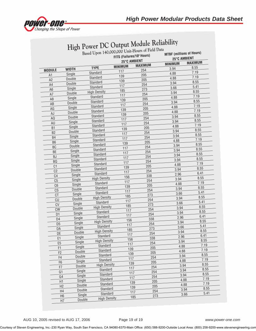
AUG 10, 2005 revised to AUG 17, 2006 Page 19 of 19 www.power-one.com
High Power DC Output Module ReliabilityBased Upon 140,000,000 Unit-Hours of Field Data
FITS (Failures/109 Hours) MTBF (millions of Hours)
25°C AMBIENT 25°C AMBIENT
MODULE WIDTH TYPE MINIMUM MAXIMUM MINIMUM MAXIMUM
A1 Single Standard 117 254 3.94 8.55
A2 Double Standard 139 205 4.88 7.19
A4 Double Standard 139 205 4.88 7.19
A6 Single Standard 117 254 3.94 8.55
A7 Double High Density 185 273 3.66 5.41
A8 Single Standard 117 254 3.94 8.55
AB Double Standard 139 205 4.88 7.19
AG Single Standard 117 254 3.94 8.55
AJ Double Standard 139 205 4.88 7.19
AQ Double Standard 139 205 4.88 7.19
AU Single Standard 117 254 3.94 8.55
B1 Single Standard 117 254 3.94 8.55
B2 Double Standard 139 205 4.88 7.19
B4 Single Standard 117 254 3.94 8.55
B6 Single Standard 117 254 3.94 8.55
BC Double Standard 139 205 4.88 7.19
BE Single Standard 117 254 3.94 8.55
BJ Single Standard 117 254 3.94 8.55
BQ Single Standard 117 254 3.94 8.55
C1 Single Standard 117 254 3.94 8.55
C2 Double Standard 139 205 4.88 7.19
C4 Single Standard 117 254 3.94 8.55
C5 Single High Density 156 338 2.96 6.41
C6 Single Standard 117 254 3.94 8.55
CS Double Standard 139 205 4.88 7.19
CT Single Standard 117 254 3.94 8.55
CU Double High Density 185 273 3.66 5.41
CV Single Standard 117 254 3.94 8.55
CW Double High Density 185 273 3.66 5.41
D1 Single Standard 117 254 3.94 8.55
D4 Single Standard 117 254 3.94 8.55
D5 Single High Density 156 338 2.96 6.41
DA Single Standard 117 254 3.94 8.55
DE Double High Density 185 273 3.66 5.41
E1 Single Standard 117 254 3.94 8.55
E5 Single High Density 156 338 2.96 6.41
F1 Single Standard 117 254 3.94 8.55
F2 Double Standard 139 205 4.88 7.19
F4 Double Standard 139 205 4.88 7.19
F6 Single Standard 117 254 3.94 8.55
F7 Double High Density 139 205 4.88 7.19
G1 Single Standard 117 254 3.94 8.55
G4 Single Standard 117 254 3.94 8.55
H1 Single Standard 117 254 3.94 8.55
H2 Double Standard 139 205 4.88 7.19
H4 Double Standard 139 205 4.88 7.19
H6 Single Standard 117 254 3.94 8.55
H7 Double High Density 185 273 3.66 5.41
High Power Modular Products Data Sheet
Courtesy of Steven Engineering, Inc.-230 Ryan Way, South San Francisco, CA 94080-6370-Main Office: (650) 588-9200-Outside Local Area: (800) 258-9200-www.stevenengineering.com

REV. AUG 11, 2005 Page 1 of 7 www.power-one.com
High Power Modular Products Application Note: Mechanical Drawings
DescriptionPower-One’s high power modular products can beconfigured to provide up to 21 outputs in over 10 millionvoltage and current combinations. Eighteen chassisare available from 1000 to 4000 watts; including powerfactor corrected, three-phase input, and metricmounting hardware models. Over 90 output modulesare available to provide voltages from 1 to 48VDC.Output modules have a field demonstrated MTBF ofgreater than 5 million hours. Other features include acomprehensive array of module and system interfacesignals, extensive input transient protection, andinternational regulatory agency approvals. These high-performance products have a proven track record inhigh reliability communications, semiconductor test,,and industrial applications.
Modular High Power Products Data Sheet (This maybe downloaded from www.power-one.com by usingthe AC-DC Configurable Modular Link.)
Table of ContentsSPM3/SMM3 . . . . . . . . . . . . . . . . . . . . . . . . . . . . . . . . . .2
SPF3/SMF3 HPF3/HMF3 . . . . . . . . . . . . . . . . . . . . . . . .3
SPM5/SMM5 HPF5/HMF5 HPM5/HMM5 . . . . . . . . . . .4
HPM7/HMM7 . . . . . . . . . . . . . . . . . . . . . . . . . . . . . . . . . .5
RPF5/RMF5 . . . . . . . . . . . . . . . . . . . . . . . . . . . . . . . . . . .6
RPM5/RMM5 . . . . . . . . . . . . . . . . . . . . . . . . . . . . . . . . . .7
NUCLEAR AND MEDICAL APPLICATIONS - Power-One products are not designed, intended for use in, or authorized for use as critical componentsin life support systems, equipment used in hazardous environments, or nuclear control systems without the express written consent of the respectivedivisional president of Power-One, Inc.
TECHNICAL REVISIONS - The appearance of products, including safety agency certifications pictured on labels, may change depending on thedate manufactured. Specifications are subject to change without notice.
Courtesy of Steven Engineering, Inc.-230 Ryan Way, South San Francisco, CA 94080-6370-Main Office: (650) 588-9200-Outside Local Area: (800) 258-9200-www.stevenengineering.com

High Power Modular Products Application Note:
REV. AUG 11, 2005 Page 2 of 7 www.power-one.com
Mechanical Drawing SPM3 / SMM3*
OUTPUT MODULES—CONFIGURATIONS AND INTERFACE SIGNALS
*Metric mounting chassis meet all specifications of non-metric models.
OVERALL SIZE: 11.00" x 5.50" x 5.00" (279.4mm x 139.7mm x 127.0mm)WEIGHT: 10.0 lb (4.50 kg)
Courtesy of Steven Engineering, Inc.-230 Ryan Way, South San Francisco, CA 94080-6370-Main Office: (650) 588-9200-Outside Local Area: (800) 258-9200-www.stevenengineering.com

REV. AUG 11, 2005 Page 3 of 7 www.power-one.com
High Power Modular Products Application Note: Mechanical Drawing SPF3 / SMF3* and HPF3 / HMF3*
OVERALL SIZE: 12.50" x 5.50" x 5.00" (317.5mm x 139.7mm x 127.0mm)WEIGHT: 12.5 lb (5.70 kg)
*Metric mounting chassis meet all specifications of non-metric models.
Courtesy of Steven Engineering, Inc.-230 Ryan Way, South San Francisco, CA 94080-6370-Main Office: (650) 588-9200-Outside Local Area: (800) 258-9200-www.stevenengineering.com

High Power Modular Products Application Note:
REV. AUG 11, 2005 Page 4 of 7 www.power-one.com
Mech. Drawing SPM5 / SMM5*, HPF5 / HMF5*, and HPM5 / HMM5*
OVERALL SIZE: 11.00" x 8.00" x 5.00" (279.4mm x 203.2mm x 127.0mm)WEIGHT: 15.0 lb (6.75 kg)
*Metric mounting chassis meet all specifications of non-metric models.
Courtesy of Steven Engineering, Inc.-230 Ryan Way, South San Francisco, CA 94080-6370-Main Office: (650) 588-9200-Outside Local Area: (800) 258-9200-www.stevenengineering.com

REV. AUG 11, 2005 Page 5 of 7 www.power-one.com
High Power Modular Products Application Note: Mechanical Drawing HPM7 / HMM7*
*Metric mounting chassis meet all specifications of non-metric models.
L
N
AIRFLOW
OVERALL SIZE: 13.00" x 11.00" x 5.00" (330.2mm x 279.4mm x 127.0mm)WEIGHT: 21.0 LBS (9.60 kg)
Courtesy of Steven Engineering, Inc.-230 Ryan Way, South San Francisco, CA 94080-6370-Main Office: (650) 588-9200-Outside Local Area: (800) 258-9200-www.stevenengineering.com

High Power Modular Products Application Note:
REV. AUG 11, 2005 Page 6 of 7 www.power-one.com
Mechanical Drawing RPF5 / RMF5*
OVERALL SIZE: 12.44" x 8.00" x 5.00" (316.0mm x 203.2mm x 127.0mm)WEIGHT: 21.0 lb (9.60 kg)
12.44"(316mm)1.1"
(28.0mm)0.52"(13.2mm)
5.00"(127mm)
8.00"(203.2mm)
5.75"(146mm)
1.15"(29.2mm)
1.10"(27.9mm)
0.48"(12.2mm)
6.750"(171.4mm)
0.95"(24.1mm) 2.555"
(64.9mm)6.750"
(171.4mm) 2.555"(64.9mm)
4.74"(120.5mm)
4.000"(101.6mm)
A
A
A
SIDE VIEW
BOTTOM VIEW
B B
BAB
A BA
BA
B
A B
AIR INTAKE ANDFAN GUARD (NOT SHOWN)THIS END
FAN GUARD PROTRUDES 0.24"BEYOND CHASSIS.
AIRFLOW
FOR MOUNTING, USE #8-32 UNC. (M4 X 0.7 FOR RMF5)MAXIMUM PENETRATION 0.15 (3.8mm) (HOLES MARKED"A" BOTH SIDES; HOLES MARKED "B" NEARSIDE ONLY)28 PLACES IN ALL. RECOMMENDED MOUNTINGTORQUE 5.25 INCH LBS. (0.32 N/M)
RPF5/RMF5INPUT SECTION
*Metric mounting chassis meet all specifications of non-metric models.
Courtesy of Steven Engineering, Inc.-230 Ryan Way, South San Francisco, CA 94080-6370-Main Office: (650) 588-9200-Outside Local Area: (800) 258-9200-www.stevenengineering.com

REV. AUG 11, 2005 Page 7 of 7 www.power-one.com
High Power Modular Products Application Note: Mechanical Drawing RPM5 / RMM5*
AIRFLOW
INPUT CONNECTOR ISAMP# 556882-4,CUSTOMER’S MAT INGSHOULD BE AMP# 556879-4,CONTA CTS, NEED FOUR (4),AMP# 556880-2.CONTROLCONNECTOR1
23
101112
5.750"(146.1mm)
B
B
B
B
FOR MOUNTING USE #8-32 UNC.(M4 X 0.7 FOR METRIC MOUNTING)MAXIMUM PENETRATION 0 .15"(3.8mm) (HOLES MARKED "A"BOTH SIDES, HOLES MARKED"B" NEARSIDE ONLY, HOLESMARKED "C" FARSIDE ONLY)28 PLACES IN ALL.RECOMMENDED MOUNTINGTORQUE 5.25 INCH LBS.
4.000"(101.6mm)
5.00"(127.0mm)
8.00"(203.2mm)
1.10"(27.9mm)
1.15"(29.2mm)
0.48"(12.2mm)
0.52"(13.2mm)
7.30"(185.4mm)
6.750"(171.5mm)
15.00"(381.0mm)
1.10"(28.0mm)
2.555"(64.9mm)
2.555"(64.9mm)
SIDE VIEW
BOTTOM VIEW
0.28"(7.1mm)
A
A
A
A
B
B
A A
A A
B
B
B
B
VOLTADJ.
VOLTADJ.
123
456
+
-
+
-
+
-
VOLTADJ.
+
-
+
-
123
101112
VOLTADJ.
1
2
3
4
123
456
1
2
3
4
5
6
123
456
VOLTADJ.
VOLTADJ.
123
456
INPUTSECTION
SLOT#5
SLOT#4
SLOT#3
SLOTS #1AND #2
0.95"(24.1mm)
5.00"(127.0mm)
8.00"(203.2mm)
RPM5 SLOT LOCATIONS SHOWN
CONTROL FUNCTIONSPIN FUNCTION567
1011
POWER FAIL WARNINGOVER TEMP WARNING5V @ 100mA*SIGNAL GROUNDINHIBIT
MOLEX SERIES 1625-12 #03-06-1121MATING: 1625-12 #03-06-2122CONSULT FACTORY FOR OTHERAVAILABLE CONTROL FUNCTIONS* A lesser current is available if a logic option board is used. Consult factory.
L1
L2
L3
L1
L2
L3
- CHASSIS GROUND
L1 - AC LINE
L2 - AC LINE
L3 - AC LINE
C
C
4.005"(101.7mm)
C
C
6.000"(152.4mm)
RPM5INPUT SECTION
OVERALL SIZE: 15.00" x 8.00" x 5.00" (381.0mm x 203.2mm x 127.0mm)WEIGHT: 21.0 lb (9.60 kg)
*Metric mounting chassis meet all specifications of non-metric models.
Courtesy of Steven Engineering, Inc.-230 Ryan Way, South San Francisco, CA 94080-6370-Main Office: (650) 588-9200-Outside Local Area: (800) 258-9200-www.stevenengineering.com

MPB125 Multiple-Output AC-DC Series Data Sheet
OCT 24, 2005 revised to JUN 05, 2006 Page 1 of 9 www.power-one.com
Multiple Output Model Selection
MODELOUTPUT MAXIMUM OUTPUT TOTAL RIPPLE & NOISE 1
REGULATION RANGEVOLTAGE CURRENT (AMPS), REGULATION % pk-pk(VOLTS) 130 LFM %
MPB125-2003 2 +3.3V 30A ±3% 1% 3.20V to 3.40V+12V 0.5A ±5% 1% 11.80V to 12.60V
MPB125-2005 3, 4 +5V 25A ±3% 1% 4.85V to 5.15V+12V 0.5A ±5% 1% 10.80V to 12.60V
MPB125-2012 3, 4, 5 +12V 10.5A ±3% 1% 11.64V to 12.36V12V 0.5A ±5% 1% 11.40V to 12.60V
MPB125-2015 3, 4, 5 +15V 8.3A ±3% 1% 14.54V to 15.45V12V 0.5A ±5% 1% 11.40V to 12.60V
MPB125-2024 3, 4, 5 +24V 5.2A ±3% 1% 23.28V to 24.72V12V 0.5A ±5% 1% 11.40V to 12.60V
MPB125-2048 3, 4, 5 +48V 2.6A ±3% 1% 46.56V to 49.44V12V 0.5A ±5% 1% 11.40V to 12.60V
MPB125-30006 +5V 16.5A ±4% 1% 8 4.85V to 5.25V
+12V 5A/9Apk ±5% 1% 11.40V to 12.60V-12V 0.5A ±5% 1% -11.40V to -12.60V
MPB125-42506
+2.5V 12A 7 ±3% 2% 2.42V to 2.58V+5V 15A 7 ±4% 1% 8 4.85V to 5.25V+12V 5A/9Apk ±5% 1% 11.40V to 12.60V-12V 0.5A ±5% 1% -11.40V to -12.60V
MPB125-43506
+3.3V 10A 7 ±3% 1.5% 3.20V to 3.40V+5V 15A 7 ±4% 1% 8 4.85V to 5.25V+12V 5A/9Apk ±5% 1% 11.40V to 12.60V-12V 0.5A ±5% 1% -11.40V to -12.60V
NOTES:1 Maximum peak-to-peak noise expressed as a percentage of output voltage, 20 MHz bandwidth.2 For MPB125-2003 and -2003D, a minimum airflow of 10 CFM is required to provide the maximum current of 30A on V1.
V1 current can be as high as 25A with a minimum airflow of 5 CFM.3 Maximum forced-air output power is 125 watts with 5 CFM airflow.4 Maximum convection output power is 70 watts.5 V2 is isolated from V1 and can be used as a negative or positive output.6 12V output’s peak load maximum duration is 30 seconds. Average current must not exceed 5A.7 Maximum power of 80 watts from V1 + V2 with 5 CFM forced-air cooling. See Application Note #M3 for details.8 For loads less than 10 watts on V1 + V2 + V3, ripple and noise on the +5V output is Max. 2% peak-to-peak.
• RoHS lead free and lead-solder-exempt products are available• High power density in an industry-standard 3" x 5" footprint• Power Factor Correction (PFC) meets EN61000-3-2• Main output remote sense• Power Good signals• CE marked to Low Voltage Directive• Input transient & ESD compliance to
EN61000-4-2/-3/-4/-5• MTBF In excess of 1M hours based upon field data• Optional remote on/off with 5V standby
(See page 4 for ordering information)
Features
The MPB125 Series incorporates patented high efficiency circuitry, high power density and active Power Factor Correction (PFC)to meet the requirements of networking and data communications systems, as well as commercial and industrial configurations.Dual output units deliver a regulated main output plus a second 12V output for fans or other system functions. Multiple output modelsprovide tightly regulated DC power in a variety of configurations. The MPB125 is rated for convection as well as forced-air cooling.Full output power is available with as few as 5 Cubic Feet per Minute (CFM) forced-air cooling with the exception of the MPB125-2003 and -2003D which need only 10 CFM for full power. Optional remote on/off with standby power is also provided (see Options).The MPB125 product line is approved to the latest international regulatory standards, and displays the CE Mark.
Description
Courtesy of Steven Engineering, Inc.-230 Ryan Way, South San Francisco, CA 94080-6370-Main Office: (650) 588-9200-Outside Local Area: (800) 258-9200-www.stevenengineering.com

MPB125 Multiple-Output AC-DC Series Data Sheet
OCT 24, 2005 revised to JUN 05, 2006 Page 2 of 9 www.power-one.com
Interface Signals and Internal ProtectionPARAMETER CONDITIONS/DESCRIPTION MIN NOM MAX UNITS
Overvoltage Protection V1 of dual and triple output models; V1 & V2 outputs of 4-output models.MPB125-2003 and -2003D 3.67 4.80
MPB125-4250 (V1) 3.20 4.00MPB125-4350 (V1) 3.76 4.80
VDC5V Output of MPB125-2005 and -2005D, MPB125-3000, or MPB125-4X50 5.74 7.00
MPB125-2012 13.5 16.5MPB125-2015 17.0 19.0MPB125-2024 26.9 31.1MPB125-2048 57.6 62.4
Overload Protection Fully protected against output short circuit or overload. Automatic recovery uponremoval of overload condition. MPB125-2003, -2003D -2005, and -2005D latch OFF if overload occurs on V1 which requires an AC reset.
Remote Sense (Note 2) Total (+sense and -sense) voltage compensation for cable losses on Dual Output Models dual output models. 500 mVRemote Sense (Note 2) On models MPB125-4250 and -4350 remote sense is provided on Triple & Quad Output Models the 2.5 and 3.3V outputs, respectively.
MPB125-3000 does not have positive remote sense.Total voltage compensation for cable losses on +Sense. 200 mVTotal voltage compensation for cable losses on -Sense. 100
NOTES: 1) For MPB125-2003, a minimum airflow of 10 CFM is required to provide the maximum current of 30A on V1. V1 current can be as high as 25A with a minimum airflow of 5 CFM.
2) -Sense must be connected to output common or load common for proper power supply operation.
Input SpecificationsPARAMETER CONDITIONS/DESCRIPTION MIN NOM MAX UNITS
Input Voltage- AC Continuous input range. 90 264 VACInput Frequency AC Input. 47 63 HzBrownout Protection Lowest AC input voltage that regulation is maintained with full rated loads. 90 VACHold-up Time Over full AC input voltage range at full rated load. 17 msInput Current 90 VAC at full rated load. 1.8 ARMS
Input Protection Non-user serviceable internally located AC input line fuse, 250 VAC, 3.15A.Inrush Surge Current Internally limited by thermistor, 110VAC: 23 APK
one cycle, 25° C. 220VAC: 46Power Factor Circuitry Active PFC meets requirements of EN61000-3-2.Operating Frequency Switching frequency of main transformer. 45 kHz
Output SpecificationsPARAMETER CONDITIONS/DESCRIPTION MIN NOM MAX UNITS
Efficiency Full Load, 230VAC. Varies with distribution of loads among outputs. 73 80 85 %(Minimum efficiency reflects that of MPB125-2003D and -2005D models.)
Minimum Loads V1 + V2 + V3 for MPB125-4XXX and -3000. 5WattsV1 for MPB125-2XXX for full regulation on V2. All models operate 5
at no load without any damage and meet all specs on V1 above 0 amps.Ripple and Noise Full load, 20 MHz bandwidth. See Model Selection ChartOutput Power (Note 1) At 5 CFM forced-air cooling. See Application Note #M3 for details. 125 Watts
Convection: Consult FactoryOvershoot /Undershoot Output voltage overshoot/undershoot at turn-on. 10 %Regulation Varies by output. Total regulation includes: line changes from 85-132 VAC See Model Selection Chart
or 170-264 VAC, changes in load starting at 20% load and changing to 100% load.Transient Response Maximum deviation due to a 25% load change with unit at 75% load.
All models except MPB125-2005 and -2005D. 3%Model MPB125-2005 and -2005D. 5
Turn-on Delay Time required for initial output voltage stabilization. 0.2 1.5 SecTurn-on Rise Time Time required for output voltage to rise from 10% to 90% except for MPB125-2005 0.2 20 ms
and -2005D.MPB125-2005 and MPB125-2005D. 1 100 ms
Courtesy of Steven Engineering, Inc.-230 Ryan Way, South San Francisco, CA 94080-6370-Main Office: (650) 588-9200-Outside Local Area: (800) 258-9200-www.stevenengineering.com

MPB125 Multiple-Output AC-DC Series Data Sheet
OCT 24, 2005 revised to JUN 05, 2006 Page 3 of 9 www.power-one.com
Safety, Regulatory, and EMI SpecificationsPARAMETER CONDITIONS/DESCRIPTION MIN NOM MAX UNITS
Agency Approvals UL60950-1.CSA 22.2 No. 60950-1.EN60950 (TÜV).IEC60950-1.
Dielectric Withstand Voltage AC to chassis. 1500 VACInput to output. 3000 VDC
Electromagnetic Interference EN55022 Conducted. B ClassESD Susceptibility Per EN61000-4-2, Level 4 8 kVFlicker Per EN61000-3-3.Radiated Susceptibility Per EN61000-4-3. 3 V/mEFT/Burst Per EN61000-4-4. 1 kVInput Transient Protection Per EN61000-4-5, Level 3, 2 kV (Line-to-Gnd) minimum, 1 kV (Line-to-Line) minimum.RF Immunity Per EN61000-4-6. 0.15 to 80 MHz (1 kHz sinewave) 3 V/mMagnetic Fields Per EN61000-4-8. 1 A/mVoltage Dips Per EN61000-4-11.Insulation Resistance Input to output. 10 M�
Leakage Current Per EN60950 (264 VAC) 1.0 mA
Interface Signals and Internal Protection (Cont.)PARAMETER CONDITIONS/DESCRIPTION MIN NOM MAX UNITS
Power Good Signal AC/DC indicator - This signal indicates the status of the AC input or DC outputs.When there is sufficient AC voltage and the outputs are operating normally, anopen collector signal is provided.Turn-On delay time from application of AC: 50 500Warning time before outputs go out of regulation: 5 msWarning time before outputs deviate ±10% from the nominal value: 15
Sync Current 20 mAPull-up Voltage 30 V
Power Supply OK Signal Provided on dual-output models. Open collector signal intended to drive an LED.Closed collector occurs when the Power Good Signal is in its open collector state.
Sync Current 20 mAPull-up Voltage 30 V
Thermal Shutdown Protected against overtemperature conditions.Unit recovers when overtemperature condition is removed.
Current Share Provided on dual-output models. Up to 4 units can be connected in parallel.There are some limits for parallel operation. See MPB125 Applications Note. N+1 redundancy is provided. V2 needs an external isolation diode for N+1 operation. An external diode is required on MPB125-2003 and MPB125-2005 models for redundancy on both V1 and V2, or when ordering, you can specify MPB125-2003D or -2005D which have an internal isolation diode.
Isolation Diode Internal isolation diode is provided on V1 for all dual-output models except the MPB125-2003 and MPB125-2005. Specify MPB125-2003D or MPB125-2005D,respectively, if an internal isolation diode is required for these models.
Courtesy of Steven Engineering, Inc.-230 Ryan Way, South San Francisco, CA 94080-6370-Main Office: (650) 588-9200-Outside Local Area: (800) 258-9200-www.stevenengineering.com

MPB125 Multiple-Output AC-DC Series Data Sheet
OCT 24, 2005 revised to JUN 05, 2006 Page 4 of 9 www.power-one.com
Environmental SpecificationsPARAMETER CONDITIONS/DESCRIPTION MIN NOM MAX UNITS
Altitude Operating 10K ASL FeetNon-Operating 50K
Operating Temperature Derate linearly from 50 to 70°C to 50% power at 70°C. At 100% load: 0 50 °CMPB125 models will operate at -20°C, but will not meet all specifications.
Storage Temperature -40 85 °CForced-Air Cooling 1 Forced-air cooling of 5 CFM is required for full output power except for
MPB125-2003 and -2003D. Air velocity is measured with power supply mounted on 0.375" (9.5mm) standoffs. Airflow direction is from the input section to the output section. See Application Note #M3 for details.
Temperature Coefficient Included in total regulation of outputs.Relative Humidity Non-Condensing. 5 95 %RHShock Operating: 11 ±3ms, 3 axes, Half Sine. 15 Gpk
Non-operating: 11 ±3ms, 3 axes, Half Sine. 40Vibration Operating: Random vibration, 5-500 Hz, 10 minutes each axis. 2.4 GRMS
Non-Operating: Random vibration, 5-500 Hz, 10 minutes each axis. 6.0 GRMS
OptionsDESCRIPTION NOTES
Remote On/Off Remote On/Off is a TTL-comatible signal. A logic “high” or open circuit turns the unit on. Reverse inhibit logic can be achievedStandby Output by changing the position of the J6 connector. A logic “low” inhibits all outputs except the 5V standby. At remote off, the Power(Option R) Good signal will warn the host equipment 2 milliseconds before the main output goes out of regulation. The rating of the
standby output is +5V @ 0.2 Amps. Total regulation is ±5 %. Maximum noise and ripple is 50 mV peak-to-peak @ a 20 MHzbandwidth.
NOTE: The addition of Option “R” increases the supply width from 3.0 to 3.8 inches. Consult factory for availability.
NOTES: 1 For MPB125-2003 and -2003D, a minimum airflow of 10 CFM is required to provide the maximum current of 30A on V1. V1 current can be as high as 25A with a minimum airflow of 5 CFM.
Ordering Information:OPTIONS SUFFIXES TO ADD TO PART NUMBER
RoHS lead solder exempt 1 No RoHS suffix character required.RoHS compliant for all 6 substances Add “G” as the last character of the part number.1 The solder exemption refers to all the restricted materials except lead in solder.
Courtesy of Steven Engineering, Inc.-230 Ryan Way, South San Francisco, CA 94080-6370-Main Office: (650) 588-9200-Outside Local Area: (800) 258-9200-www.stevenengineering.com

MPB125 Multiple-Output AC-DC Series Data Sheet
OCT 24, 2005 revised to JUN 05, 2006 Page 5 of 9 www.power-one.com
MPB125-2012-2015-2024-2048
J1 Housing 09-50-8031
Pins 08-52-0113
J2 Housing 09-50-8061
Pins 08-52-0113
J3 Housing 22-01-3067
Pins 08-50-0114
J4 Housing 22-01-3027
Pins 08-50-0114
J 1 - A C INPUT CONNECTOR
J 2 - V 1 DC OUTPUTCONNECTOR
FASTENERCLEARANCEAREA (4 PL)
PIN #1
SAFETY GROUNDCONNECTION POINT
PRINTED CIRCUIT BOARD
SCREWS SHOWNFOR REFERENCEONLY
TOP VIEW
SIDE VIEW
WEIGHT: 0.63 lb. (0.3 kg)
Pin 1 NEUTRAL
Pin 2 NO PIN
Pin 3 LINE
Pin 1 +12V
Pin 2 +12V RTN
J4 -
Pin 1
Pin 2
Pin 3
Pin 4
Pin 5
Pin 6
+12V
+12V
+12V
RTN
RTN
RTN
+24V
+24V+24V
RTN
RTN
RTN
+48V
+48V
+48V
RTN
RTN
RTN
J2 - MPB125-2012 -2024
+15V
+15V
+15V
RTN
RTN
RTN
-2015 -2048
Pin 1
Pin 2
Pin 3
Pin 4
Pin 5
Pin 6
RTN
- SENSE
+ SENSE
CURRENT SHARE
POWER GOOD
POWER SUPPLY OK
J3 -
J3- SIGNALCONNECTOR
PIN #1
PIN #1
PIN #1
J4- V2 DC OUTPUTCONNECTOR
5.00"(127.0)
4.55"(115.57)
2.78"(70.6)
3.00"(76.2)
2.56"(65.02)
Ø 0.16" (4 PL)(4.06)
1.25"(31.75)
1.00"(25.4)
0.06"(1.5)
0.19"(4.8)
END VIEW
Mechanical Drawing (-2012, -2015, -2024, & -2048 Models)
Mating ConnectorsNOTE: Part numbers are MOLEX; equivalents are acceptable.
Courtesy of Steven Engineering, Inc.-230 Ryan Way, South San Francisco, CA 94080-6370-Main Office: (650) 588-9200-Outside Local Area: (800) 258-9200-www.stevenengineering.com

MPB125 Multiple-Output AC-DC Series Data Sheet
OCT 24, 2005 revised to JUN 05, 2006 Page 6 of 9 www.power-one.com
MPB125-2005
J1 Housing 09-50-8031
Pins 08-52-0113
J2 Housing 09-50-8103
Pins 08-52-0113
J3 Housing 22-01-3057
Pins 08-50-0114
J4 Housing 22-01-3027
Pins 08-50-0114
J1 - AC INPUT CONNECTOR
J2 - V1 DC OUTPUT
CONNECTOR
FASTENER
CLEARANCE
AREA (4 PL)
PIN #1
SAFETY GROUND
CONNECTION POINT
PRINTED CIRCUIT BOARD
SCREWS SHOWN
FOR REFERENCE
ONLY
TOP VIEW
SIDE VIEW
WEIGHT: 0.63 lb. (0.3 kg)
Pin 1 NEUTRAL
Pin 2 NO PIN
Pin 3 LINE
Pin 1 +12V
Pin 2 +12V RTN
J4 -
Pin 1
Pin 2
Pin 3
Pin 4
Pin 5
Pin 6
J2 -
Pin 7
Pin 1
Pin 2
Pin 3
Pin 4
Pin 5
SHARE
- SENSE
+ SENSE
POWER SUPPLY OK
POWER GOOD
J3 -
J3- SIGNAL
CONNECTOR
PIN #1
PIN #1
PIN #1
J4- V2 DC OUTPUT
CONNECTOR
5.00"
(127.0)
4.55"
(115.57)
2.78"
(70.6)
3.00"
(76.2)
2.56"
(65.02)
Ø 0.16" (4 PL)
(4.06)
1.25"
(31.75)
1.00"
(25.4)
0.06"
(1.5)
0.19"
(4.8)
Pin 8
Pin 9
Pin 10
+5V
+5V
+5V
+5V
+5V
RTN
MPB125
-2005
RTN
RTN
RTN
RTN
+3.3V
+3.3V
+3.3V
+3.3V
+3.3V
RTN
MPB125
-2003
RTN
RTN
RTN
RTN
END VIEW
Mechanical Drawing (-2003, -2003D, -2005, and -2005D Models)
Mating ConnectorsNOTE: Part numbers are MOLEX; equivalents are acceptable.
Courtesy of Steven Engineering, Inc.-230 Ryan Way, South San Francisco, CA 94080-6370-Main Office: (650) 588-9200-Outside Local Area: (800) 258-9200-www.stevenengineering.com

MPB125 Multiple-Output AC-DC Series Data Sheet
OCT 24, 2005 revised to JUN 05, 2006 Page 7 of 9 www.power-one.com
Mating ConnectorsNOTE: Part numbers are MOLEX; equivalents are acceptable.
5.00"
(127.0)
4.55"
(115.57)
2.78"
(70.6)
J1- INPUT
CONNECTOR J2 - DC OUTPUT
CONNECTOR
J3
FASTENER
CLEARANCE
AREA (4 PL)
PIN #1
PIN #1
PIN #1
SAFETY GROUND
CONNECTION POINT
PRINTED CIRCUIT BOARD
SCREWS SHOWN
FOR REFERENCE
ONLY
2.56"
(65.02)
1.25"
(31.75)
0.19"
(4.8)
0.06"
(1.5)
1.00"
(25.4)
3.00"
(76.2)
Ø 0.16" (4 PL)
(4.06)
TOP VIEW
SIDE VIEW
J1 - AC INPUT CONNECTOR
Pin 1
Pin 2
Pin 3
Pin 4
Pin 5
Pin 6
Pin 7
Pin 8
Pin 9
Pin 10
Pin 11
Pin 12
Pin 13
Pin 14
-12V
+12V
N/C
N/C
N/C
RTN
RTN
RTN
RTN
RTN
+5V
+5V
+5V
+5V
-12V
+12V
+2.5V
+2.5V
+2.5V
RTN
RTN
RTN
RTN
RTN
+5V
+5V
+5V
+5V
-12V
+12V
+3.3V
+3.3V
+3.3V
RTN
RTN
RTN
RTN
RTN
+5V
+5V
+5V
+5V
Pin 1 -SENSE
Pin 2 +SENSE
Pin 3 POWER GOOD
J2 -
J3 -
Pin 1 NEUTRAL
Pin 2 NO PIN
Pin 3 LINE
MPB125
-3000
MPB125
-4250
MPB125
-4350
WEIGHT: 0.63 lb. (0.3 kg)
END VIEW
Mechanical Drawing (-3000, -4250, & -4350 Models)
MPB125-3000-4250-4350
J1 Housing 09-50-8033Pins 08-52-0113
J2 Housing 09-50-8143Pins 08-52-0113
J3 Housing 22-01-3037Pins 08-50-0114
Courtesy of Steven Engineering, Inc.-230 Ryan Way, South San Francisco, CA 94080-6370-Main Office: (650) 588-9200-Outside Local Area: (800) 258-9200-www.stevenengineering.com

MPB125 Multiple-Output AC-DC Series Data Sheet
OCT 24, 2005 revised to JUN 05, 2006 Page 8 of 9 www.power-one.com
Mechanical Drawing (-2012R, -2015R, -2024R, & -2048R Models)
MPB125 Series “R” Option
J1 - AC INPUT CONNECTOR
J2 - V1 DC OUTPUT
CONNECTOR
FASTENER
CLEARANCE
AREA (4 PL)
PIN #1
SAFETY GROUND
CONNECTION POINT
PRINTED CIRCUIT BOARD
SCREWS SHOWN
FOR REFERENCE
ONLY
TOP VIEW
SIDE VIEW
WEIGHT: 0.63 lb. (0.3 kg)Pin 1 NEUTRAL
Pin 2 NO PIN
Pin 3 LINE
Pin 1 +12V
Pin 2 +12V RTN
J4 -
Pin 1
Pin 2
Pin 3
Pin 4
Pin 5
Pin 6
+12V
+12V
+12V
RTN
RTN
RTN
+24V
+24V
+24V
RTN
RTN
RTN
+48V
+48V
+48V
RTN
RTN
RTN
J2 - MPB125
-2012 -2024
+15V
+15V
+15V
RTN
RTN
RTN
-2015 -2048
Pin 1
Pin 2
Pin 3
Pin 4
Pin 5
Pin 6
RTN
- SENSE
+ SENSE
CURRENT SHARE
POWER GOOD
POWER SUPPLY OK
J3 -
J3- SIGNAL
CONNECTOR
PIN #1
PIN #1
PIN #1
J4- V2 DC OUTPUT
CONNECTOR
5.00"
(127.0)
4.55"
(115.57)
2.78"
(70.6)
0.80"
(20.3)
1.025"
(26.04)
3.80"
(97)
2.56"
(65.02)
Ø 0.16" (6 PL)
(4.06)
1.25"
(31.75)
1.00"
(25.4)
0.06"
(1.5)
0.19"
(4.8)
J5
PIN #1
Pin 1
Pin 2
Pin 3
RTN
REMOTE
ON/OFF
+5V
STANDBY
J5 -
END VIEW
RECOMMENDED
MOUNTING
OPTIONAL
MOUNTING
J6
POSITION FOR
STANDARD
INHIBIT LOGIC
POSITION FOR
REVERSE
INHIBIT LOGIC
MPB125-2012-2015-2024-2048
J1 Housing 09-50-8033
Pins 08-52-0113
J2 Housing 09-50-8063
Pins 08-52-0113
J3 Housing 22-01-3067
Pins 08-50-0114
J4 Housing 22-01-3027
Pins 08-50-0114
J5 Housing 22-01-3037
Pins 08-50-0114
Mating ConnectorsNOTE: Part numbers are MOLEX; equivalents are acceptable.
Courtesy of Steven Engineering, Inc.-230 Ryan Way, South San Francisco, CA 94080-6370-Main Office: (650) 588-9200-Outside Local Area: (800) 258-9200-www.stevenengineering.com

MPB125 Multiple-Output AC-DC Series Data Sheet
OCT 24, 2005 revised to JUN 05, 2006 Page 9 of 9 www.power-one.com
MPB125-3000R-4250R-4350R
J1 Housing 09-50-8033Pins 08-52-0113
J2 Housing 09-50-8143Pins 08-52-0113
J3 Housing 22-01-3037Pins 08-50-0114
J5 Housing 22-01-3037Pins 08-50-0114
Mechanical Drawing (-3000R, -4250R, & -4350R Models)
MPB125 Series “R” Option
5.00"
(127.0)
4.55"
(115.57)
2.78"
(70.6)
3.80"
(97)
J1- INPUT
CONNECTOR
J5
J2 - DC OUTPUT
CONNECTOR
J3
FASTENER
CLEARANCE
AREA (6 PL)
PIN #1
PIN #1
PIN #1
SAFETY GROUND
CONNECTION POINTSCREWS SHOWN
FOR REFERENCE
ONLY
2.56"
(65.02)
1.025"
(26.04)
0.80"
(20.3)
0.06"
(1.5)
Ø 0.16" (6 PL)
(4.06)
TOP VIEW
PRINTED CIRCUIT BOARD
1.25"
(31.75)
0.19"
(4.8)
1.00"
(25.4)
SIDE VIEW
J1 - AC INPUT CONNECTOR
Pin 1
Pin 2
Pin 3
Pin 4
Pin 5
Pin 6
Pin 7
Pin 8
Pin 9
Pin 10
Pin 11
Pin 12
Pin 13
Pin 14
-12V
+12V
N/C
N/C
N/C
RTN
RTN
RTN
RTN
RTN
+5V
+5V
+5V
+5V
-12V
+12V
+2.5V
+2.5V
+2.5V
RTN
RTN
RTN
RTN
RTN
+5V
+5V
+5V
+5V
-12V
+12V
+3.3V
+3.3V
+3.3V
RTN
RTN
RTN
RTN
RTN
+5V
+5V
+5V
+5V
J2 -
Pin 1 -SENSE
Pin 2 +SENSE
Pin 3 POWER GOOD
J3 -
Pin 1
Pin 2
Pin 3
RTN
REMOTE
ON/OFF
+5V
STANDBY
J5 -
Pin 1 NEUTRAL
Pin 2 NO PIN
Pin 3 LINE
MPB125
-3000
MPB125
-4250
MPB125
-4350
WEIGHT: 0.63 lb. (0.3 kg)
END VIEW
RECOMMENDED
MOUNTING
OPTIONAL
MOUNTING
J6
POSITION FOR
STANDARD
INHIBIT LOGIC
POSITION FOR
REVERSE
INHIBIT LOGIC
PIN #1
Mating ConnectorsNOTE: Part numbers are MOLEX; equivalents are acceptable.
NUCLEAR AND MEDICAL APPLICATIONS - Power-One products are not designed, intended for use in, or authorized for use as critical componentsin life support systems, equipment used in hazardous environments, or nuclear control systems without the express written consent of the respectivedivisional president of Power-One, Inc.
TECHNICAL REVISIONS - The appearance of products, including safety agency certifications pictured on labels, may change depending on thedate manufactured. Specifications are subject to change without notice.
Courtesy of Steven Engineering, Inc.-230 Ryan Way, South San Francisco, CA 94080-6370-Main Office: (650) 588-9200-Outside Local Area: (800) 258-9200-www.stevenengineering.com

MPB125 Single-Output AC-DC Series Data Sheet
MAY 27, 2005 revised to JUN 05, 2006 Page 1 of 4 www.power-one.com
Single Output Model Selection
MODELOUTPUT MAXIMUM OUTPUT TOTAL
ADJUSTMENT RANGEVOLTAGE CURRENT (AMPS), REGULATION RIPPLE & NOISE 1(VOLTS) 130 LFM % % pk-pk
MPB125-1012 2, 3 12V 10.5A ±1% 1% 11.76 to 12.24V
• RoHS lead free and lead-solder-exempt products areavailable
• High power density in an industry-standard 3" x 5"footprint
• Power Factor Correction (PFC) meets EN61000-3-2• CE marked to Low Voltage Directive (Pending)• Input transient & ESD compliance to
EN61000-4-2/-3/-4/-5• MTBF In excess of 1M hours based upon field data• Output adjustment potentiometer
Features
The MPB125 Series incorporates patented high efficiency circuitry, high power density and active Power FactorCorrection (PFC) to meet the requirements of networking and data communications systems, as well as commercialand industrial configurations.MPB125 single-output models deliver a fully-regulated output. The MPB125 is rated for convection as well as forced-air cooling. Full output power is available with as few as 5 Cubic Feet per Minute (CFM) forced-air cooling.The MPB125 product line is approved to the latest international regulatory standards and displays the CE Mark.
Description
Input SpecificationsPARAMETER CONDITIONS/DESCRIPTION MIN NOM MAX UNITS
Input Voltage- AC Continuous input range. 90 264 VACInput Frequency AC Input. 47 63 HzBrownout Protection Lowest AC input voltage that regulation is maintained with full rated loads. 90 VACHold-up Time Over full AC input voltage range at full rated load. 17 msInput Current 90 VAC at full rated load. 1.8 ARMS
Input Protection Non-user serviceable internally located AC input line fuse, 3.15A.Inrush Surge Current Internally limited by thermistor, 110VAC: 23 APK
one cycle, 25° C. 220VAC: 46Power Factor Circuitry Active PFC meets requirements of EN61000-3-2.Operating Frequency Switching frequency of main transformer. 45 kHz
NOTES:1 Maximum peak-to-peak noise expressed as a percentage of output voltage, 20 MHz bandwidth.2 Maximum forced-air output power is 125 watts with 5 CFM airflow.3 Maximum convection output power is 70 watts.
Ordering Information:OPTIONS SUFFIXES TO ADD TO PART NUMBER
RoHS lead solder exempt 1 No RoHS suffix character required.RoHS compliant for all 6 substances Add “G” as the last character of the part number.1 The solder exemption refers to all the restricted materials except lead in solder.
Courtesy of Steven Engineering, Inc.-230 Ryan Way, South San Francisco, CA 94080-6370-Main Office: (650) 588-9200-Outside Local Area: (800) 258-9200-www.stevenengineering.com

MPB125 Single-Output AC-DC Series Data Sheet
MAY 27, 2005 revised to JUN 05, 2006 Page 2 of 4 www.power-one.com
Interface Signals and Internal ProtectionPARAMETER CONDITIONS/DESCRIPTION MIN NOM MAX UNITS
Overvoltage Protection MPB125-1012 13.5 16.5 VDCOverload Protection Fully protected against output short circuit or overload. Automatic recovery upon
removal of overload condition.Thermal Shutdown Protected against overtemperature conditions.
Unit recovers when overtemperature condition is removed.
Output SpecificationsPARAMETER CONDITIONS/DESCRIPTION MIN NOM MAX UNITS
Efficiency Full Load, 230VAC. 80 %Minimum Loads No Minimum Load is Required AmpsRipple and Noise Full load, 20 MHz bandwidth. See Model Selection ChartOutput Power (Note 1) At 5 CFM forced-air cooling. See Application Note #M3 for details. 125 Watts
Convection: 70Overshoot /Undershoot Output voltage overshoot/undershoot at turn-on. 10 %Regulation Varies by output. Total regulation includes: line changes from 85-132 VAC See Model Selection Chart
or 170-264 VAC, changes in load starting at 20% load and changing to 100% load.Transient Response Maximum deviation due to a 25% load change with unit at 75% load. 3 %Turn-on Delay Time required for initial output voltage stabilization. 0.2 1.5 SecTurn-on Rise Time Time required for output voltage to rise from 10% to 90%. 0.2 20 ms
Safety, Regulatory, and EMI SpecificationsPARAMETER CONDITIONS/DESCRIPTION MIN NOM MAX UNITS
Agency Approvals UL60950-1.CSA 22.2 No. 60950-1.EN60950 (TÜV).IEC60950-1
Dielectric Withstand Voltage AC to chassis. 1500 VACInput to output. 3000 VDC
Electromagnetic Interference EN55022 Conducted. B ClassESD Susceptibility Per EN61000-4-2, Level 4 8 kVFlicker Per EN61000-3-3.Radiated Susceptibility Per EN61000-4-3. 3 V/mEFT/Burst Per EN61000-4-4. 1 kVInput Transient Protection Per EN61000-4-5, Level 3, 2 kV (Line-to-Gnd) minimum, 1 kV (Line-to-Line) minimum.RF Immunity Per EN61000-4-6. 0.15 to 80 MHz (1 kHz sinewave) 3 V/mMagnetic Fields Per EN61000-4-8. 1 A/mVoltage Dips Per EN61000-4-11.Insulation Resistance Input to output. 10 M�
Leakage Current Per EN60950 (264 VAC) 1.0 mA
APPROVED
Courtesy of Steven Engineering, Inc.-230 Ryan Way, South San Francisco, CA 94080-6370-Main Office: (650) 588-9200-Outside Local Area: (800) 258-9200-www.stevenengineering.com

MPB125 Single-Output AC-DC Series Data Sheet
MAY 27, 2005 revised to JUN 05, 2006 Page 3 of 4 www.power-one.com
Environmental SpecificationsPARAMETER CONDITIONS/DESCRIPTION MIN NOM MAX UNITS
Altitude Operating 10K ASL FeetNon-Operating 50K
Operating Temperature Derate linearly from 50 to 70°C to 50% power at 70°C At 100% load: 0 50 °CStorage Temperature -40 85 °CForced-Air Cooling Forced-air cooling of 5 CFM is required for full output power. Air velocity
is measured with power supply mounted on 0.375" (9.5mm) standoffs. Airflow direction is from the input section to the output section. See Application Note for details.
Temperature Coefficient Included in total regulation of outputs.Relative Humidity Non-Condensing. 5 95 %RHShock Operating: 11 ±3ms, 3 axes, Half Sine. 15 Gpk
Non-operating: 11 ±3ms, 3 axes, Half Sine. 40Vibration Operating: Random vibration, 5-500 Hz, 10 minutes each axis. 2.4 GRMS
Non-Operating: Random vibration, 5-500 Hz, 10 minutes each axis. 6.0 GRMS
Courtesy of Steven Engineering, Inc.-230 Ryan Way, South San Francisco, CA 94080-6370-Main Office: (650) 588-9200-Outside Local Area: (800) 258-9200-www.stevenengineering.com

MPB125-1012
J1 Housing 09-50-8033
Pins 08-52-0113
J2 Housing 09-50-8063
Pins 08-52-0113
MPB125 Single-Output AC-DC Series Data Sheet
MAY 27, 2005 revised to JUN 05, 2006 Page 4 of 4 www.power-one.com
J 1 - A C INPUT CONNECTOR
J 2 - V 1 DC OUTPUTCONNECTOR
FASTENERCLEARANCEAREA (4 PL)
PIN #1
SAFETY GROUNDCONNECTION POINT
PRINTED CIRCUIT BOARD
SCREWS SHOWNFOR REFERENCEONLY
TOP VIEW
SIDE VIEW
WEIGHT: 0.63 lb. (0.3 kg)
Pin 1 NEUTRAL
Pin 2 NO PIN
Pin 3 LINE
Pin 1
Pin 2
Pin 3
Pin 4
Pin 5
Pin 6
+12V
+12V
+12V
RTN
RTN
RTN
J2 - MPB125-1012
PIN #1
PIN #1
J4-CONNECTOR
5.00"(127.0)
4.55"(115.57)
2.78"(70.6)
3.00"(76.2)
2.56"(65.02)
Ø 0.16" (4 PL)(4.06)
1.25"(31.75)
1.00"(25.4)
0.06"(1.5)
0.19"(4.8)
END VIEW
CAUTIONDO NOT USE CONNECTOR J4. THE J4 CONNECTORIS FOR INTERNAL TESTING OF THE POWER SUPPLY BYPOWER-ONE ONLY. PINOUT IS FOR REFERENCE ONLY.
OUTPUT VOLTAGEADJUSTMENT POTENTIOMETER
Mechanical Drawing (MPB125-1012 Model)
Mating ConnectorsNOTE: Part numbers are MOLEX; equivalents are acceptable.
NUCLEAR AND MEDICAL APPLICATIONS - Power-One products are not designed, intended for use in, or authorized for use as critical componentsin life support systems, equipment used in hazardous environments, or nuclear control systems without the express written consent of the respectivedivisional president of Power-One, Inc.
TECHNICAL REVISIONS - The appearance of products, including safety agency certifications pictured on labels, may change depending on thedate manufactured. Specifications are subject to change without notice.
Courtesy of Steven Engineering, Inc.-230 Ryan Way, South San Francisco, CA 94080-6370-Main Office: (650) 588-9200-Outside Local Area: (800) 258-9200-www.stevenengineering.com

MPB150 Dual-Output AC-DC Series Data Sheet
MCD10078 Rev. 1.0, 28-Aug-08 Page 1 of 4 www.power-one.com
Model Selection
MODELOUTPUT MAXIMUM OUTPUT TOTAL RIPPLE & NOISE
REGULATION RANGEVOLTAGE CURRENT (AMPS), REGULATION % pk-pk(VOLTS) 130 LFM % (NOTE 1)
MPB150-2012G +12V 12.5A ±3% 1% 11.64V to 12.36V(NOTE 2, 3, 4) 12V 0.5A ±5% 1% 11.40V to 12.60VMPB150-2024G +24V 6.0A ±3% 1% 23.28V to 24.72V(NOTE 2, 3, 4) 12V 0.5A ±5% 1% 11.40V to 12.60VMPB150-2048G +48V 3.1A ±3% 1% 46.56V to 49.44V(NOTE 2, 3, 4) 12V 0.5A ±5% 1% 11.40V to 12.60V
NOTES: 1) Maximum peak-to-peak noise expressed as a percentage of output voltage, 20 MHz bandwidth.2) Maximum forced-air output power is 150 watts with 15 CFM airflow.3) Maximum convection output power is 70 watts.4) V2 is isolated from V1 and can be used as a negative or positive output.
• RoHS compliant for all six substances• High power density in an industry-standard 3" x 5"
footprint• Power Factor Correction (PFC) meets EN61000-3-2• Main output remote sense• Power Good signals• CE marked to Low Voltage Directive• Input transient & ESD compliance to
EN61000-4-2/-3/-4/-5
Features
The MPB150 Series incorporates patented high efficiency circuitry, high power density and active Power FactorCorrection (PFC) to meet the requirements of networking and data communications systems, as well as commercialand industrial configurations.MPB150’s deliver a regulated main output plus a second 12V output for fans or other system functions. The MPB150is rated for convection as well as forced-air cooling. Full output power is available with as few as 15 Cubic Feet perMinute (CFM) forced-air cooling.The MPB150 product line is approved to the latest international regulatory standards, and displays the CE Mark.
Description
Courtesy of Steven Engineering, Inc.-230 Ryan Way, South San Francisco, CA 94080-6370-Main Office: (650) 588-9200-Outside Local Area: (800) 258-9200-www.stevenengineering.com

MPB150 Dual-Output AC-DC Series Data Sheet
MCD10078 Rev. 1.0, 28-Aug-08 Page 2 of 4 www.power-one.com
Interface Signals and Internal ProtectionPARAMETER CONDITIONS/DESCRIPTION MIN NOM MAX UNITS
Overvoltage Protection V1 output. MPB150-2012 13.5 16.5MPB150-2024 26.9 31.1 VDCMPB150-2048 57.6 62.4
Overload Protection Fully protected against output short circuit or overload. Automatic recovery uponremoval of overload condition.
Remote Sense (Note 1) Total (+sense and -sense) voltage compensation for cable losses. 500 mVPower Good Signal AC/DC indicator - This signal indicates the status of the AC input or DC outputs.
When there is sufficient AC voltage and the outputs are operating normally, anopen collector signal is provided.Turn-On delay time from application of AC: 50 500Warning time before outputs go out of regulation: 5 msWarning time before outputs deviate ±10% from the nominal value: 15
Sink Current 20 mAPull-up Voltage 30 V
Power Supply OK Signal Provided on dual-output models. Open collector signal intended to drive an LED.Closed collector occurs when the Power Good Signal is in its open collector state.
Sink Current 20 mAPull-up Voltage 30 V
Thermal Shutdown Protected against overtemperature conditions.Unit recovers when overtemperature condition is removed.
Current Share Up to 4 units can be connected in parallel.There are some limits for parallel operation. See Applications Note. N+1 redundancy is provided. V2 needs an external isolation diode for N+1 operation.
Isolation Diode Internal isolation diode is provided on V1.
NOTES: 1) Negative (-) sense must be connected to output common or load common for proper power supply operation.
Input SpecificationsPARAMETER CONDITIONS/DESCRIPTION MIN NOM MAX UNITS
Input Voltage- AC Continuous input range. 90 264 VACInput Frequency AC Input. 47 63 HzBrownout Protection Lowest AC input voltage that regulation is maintained with full rated loads. 90 VACHold-up Time Over full AC input voltage range at full rated load. 17 msInput Current 90 VAC at full rated load. 2.2 ARMS
Input Protection Non-user serviceable internally located AC input line fuse, 250 VAC, 3.15A.Inrush Surge Current Internally limited by thermistor, 110VAC: 23 APK
one cycle, 25° C. 220VAC: 46Power Factor Circuitry Active PFC meets requirements of EN61000-3-2.Operating Frequency Switching frequency of main transformer. 45 kHz
Output SpecificationsPARAMETER CONDITIONS/DESCRIPTION MIN NOM MAX UNITS
Efficiency Full Load, 230VAC. Varies with distribution of loads among outputs. 75 80 85 %Minimum Loads V1 load for full regulation on V2. All models operate 5 Watts
at no load without any damage and meet all specs on V1 above 0 amps.Ripple and Noise Full load, 20 MHz bandwidth. See Model Selection ChartOutput Power (Note 1) At 15 CFM forced-air cooling. See Application Note for details. 150 Watts
Convection: Consult Factory.Overshoot /Undershoot Output voltage overshoot/undershoot at turn-on. 10 %Regulation Varies by output. Total regulation includes: line changes from 85-132 VAC See Model Selection Chart
or 170-264 VAC, changes in load starting at 20% load and changing to 100% load.Transient Response Maximum deviation due to a 25% load change with unit at 75% load. 3 %Turn-on Delay Time required for initial output voltage stabilization. 0.2 1.5 SecTurn-on Rise Time Time required for output voltage to rise from 10% to 90%. 0.2 20 ms
Courtesy of Steven Engineering, Inc.-230 Ryan Way, South San Francisco, CA 94080-6370-Main Office: (650) 588-9200-Outside Local Area: (800) 258-9200-www.stevenengineering.com

MPB150 Dual-Output AC-DC Series Data Sheet
MCD10078 Rev. 1.0, 28-Aug-08 Page 3 of 4 www.power-one.com
Safety, Regulatory, and EMI SpecificationsPARAMETER CONDITIONS/DESCRIPTION MIN NOM MAX UNITS
Agency Approvals UL60950-1.CSA No. 60950-1.EN60950-1.IEC60950-1.
Dielectric Withstand Voltage AC to chassis. 1500 VACInput to output. 3000 VDC
Electromagnetic Interference EN55022 Conducted. Class A 6 dBESD Susceptibility Per EN61000-4-2, Level 4 8 kVFlicker Per EN61000-3-3.Radiated Susceptibility Per EN61000-4-3. 3 V/mEFT/Burst Per EN61000-4-4. 1 kVInput Transient Protection Per EN61000-4-5, Level 3, 2 kV (Line-to-Gnd) minimum, 1 kV (Line-to-Line) minimum.RF Immunity Per EN61000-4-6. 0.15 to 80 MHz (1 kHz sinewave) 3 V/mMagnetic Fields Per EN61000-4-8. 1 A/mVoltage Dips Per EN61000-4-11.Insulation Resistance Input to output. 10 M�
Leakage Current Per EN60950 (264 VAC) 1.0 mA
Environmental SpecificationsPARAMETER CONDITIONS/DESCRIPTION MIN NOM MAX UNITS
Altitude Operating 10K ASL FeetNon-Operating 50K
Operating Temperature Derate linearly from 50 to 70°C to 50% power at 70°C. At 100% load: 0 50 °CMPB150 models will operate at -20°C, but will not meet all specifications.
Storage Temperature -40 85 °CForced-Air Cooling Forced-air cooling of 15 CFM is required for full output power. Air velocity
is measured with power supply mounted on 0.375" (9.5mm) standoffs.Airflow direction is from the input section to the output section.See Application Note for details.
Temperature Coefficient Included in total regulation of outputs.Relative Humidity Non-Condensing. 5 85 %RHShock Operating: 11 ±3ms, 3 axes, Half Sine. 15 Gpk
Non-operating: 11 ±3ms, 3 axes, Half Sine. 40Vibration Operating: Random vibration, 5-500 Hz, 10 minutes each axis. 2.4 GRMS
Non-Operating: Random vibration, 5-500 Hz, 10 minutes each axis. 6.0 GRMS
Courtesy of Steven Engineering, Inc.-230 Ryan Way, South San Francisco, CA 94080-6370-Main Office: (650) 588-9200-Outside Local Area: (800) 258-9200-www.stevenengineering.com

NUCLEAR AND MEDICAL APPLICATIONS - Power-One products are not designed, intended for use in, or authorized for use as critical componentsin life support systems, equipment used in hazardous environments, or nuclear control systems without the express written consent of the respectivedivisional president of Power-One, Inc.
TECHNICAL REVISIONS - The appearance of products, including safety agency certifications pictured on labels, may change depending on thedate manufactured. Specifications are subject to change without notice.
MPB150-2012G-2024G-2048G
J1 Housing 09-50-8031
Pins 08-52-0113
J2 Housing 09-50-8061
Pins 08-52-0113
J3 Housing 22-01-3067
Pins 08-50-0114
J4 Housing 22-01-3027
Pins 08-50-0114
MPB150 Dual-Output AC-DC Series Data Sheet
MCD10078 Rev. 1.0, 28-Aug-08 Page 4 of 4 www.power-one.com
J 1 - A C INPUT CONNECTOR
J 2 - V 1 DC OUTPUTCONNECTOR
FASTENERCLEARANCEAREA (4 PL)
PIN #1
SAFETY GROUNDCONNECTION POINT
PRINTED CIRCUIT BOARD
SCREWS SHOWNFOR REFERENCEONLY
TOP VIEW
SIDE VIEW
WEIGHT: 0.63 lb. (0.3 kg)
Pin 1 NEUTRAL
Pin 2 NO PIN
Pin 3 LINE
Pin 1 +12V
Pin 2 +12V RTN
J4 -
Pin 1
Pin 2
Pin 3
Pin 4
Pin 5
Pin 6
+12V
+12V
+12V
RTN
RTN
RTN
+24V
+24V+24V
RTN
RTN
RTN
+48V
+48V
+48V
RTN
RTN
RTN
J2 - MPB150-2012G -2024G -2048G
Pin 1
Pin 2
Pin 3
Pin 4
Pin 5
Pin 6
RTN
- SENSE
+ SENSE
CURRENT SHARE
POWER GOOD
POWER SUPPLY OK
J3 -
J3- SIGNALCONNECTOR
PIN #1
PIN #1
PIN #1
J4- V2 DC OUTPUTCONNECTOR
5.00"(127.0)
4.55"(115.57)
2.78"(70.6)
3.00"(76.2)
2.56"(65.02)
Ø 0.16" (4 PL)(4.06)
1.25"(31.75)
1.00"(25.4)
0.06"(1.5)
0.19"(4.8)
END VIEW
Mechanical Drawing (-2012G, -2024G, & -2048G Models)
Mating ConnectorsNOTE: Part numbers are MOLEX; equivalents are acceptable.
Courtesy of Steven Engineering, Inc.-230 Ryan Way, South San Francisco, CA 94080-6370-Main Office: (650) 588-9200-Outside Local Area: (800) 258-9200-www.stevenengineering.com
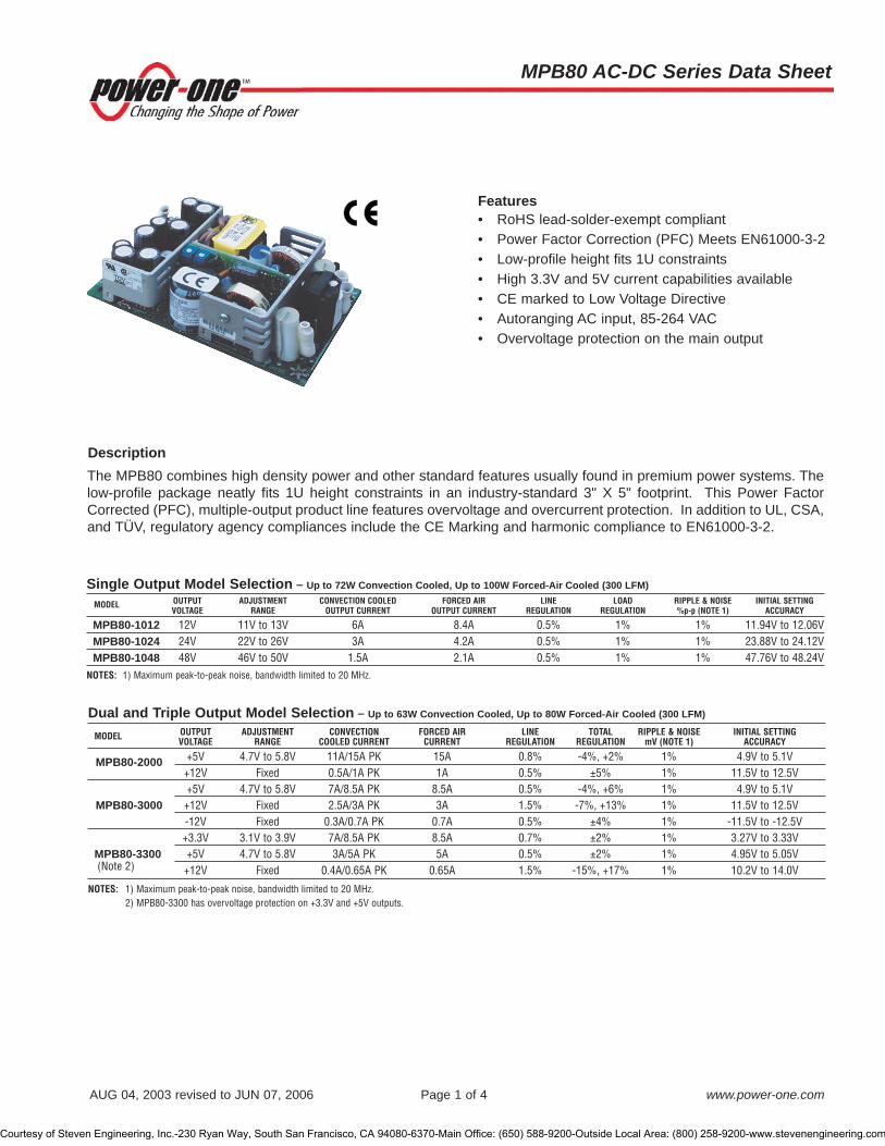
Features• RoHS lead-solder-exempt compliant• Power Factor Correction (PFC) Meets EN61000-3-2• Low-profile height fits 1U constraints• High 3.3V and 5V current capabilities available• CE marked to Low Voltage Directive• Autoranging AC input, 85-264 VAC• Overvoltage protection on the main output
Dual and Triple Output Model Selection – Up to 63W Convection Cooled, Up to 80W Forced-Air Cooled (300 LFM)
MODEL OUTPUT ADJUSTMENT CONVECTION FORCED AIR LINE TOTAL RIPPLE & NOISE INITIAL SETTINGVOLTAGE RANGE COOLED CURRENT CURRENT REGULATION REGULATION mV (NOTE 1) ACCURACY
MPB80-2000 +5V 4.7V to 5.8V 11A/15A PK 15A 0.8% -4%, +2% 1% 4.9V to 5.1V+12V Fixed 0.5A/1A PK 1A 0.5% ±5% 1% 11.5V to 12.5V+5V 4.7V to 5.8V 7A/8.5A PK 8.5A 0.5% -4%, +6% 1% 4.9V to 5.1V
MPB80-3000 +12V Fixed 2.5A/3A PK 3A 1.5% -7%, +13% 1% 11.5V to 12.5V-12V Fixed 0.3A/0.7A PK 0.7A 0.5% ±4% 1% -11.5V to -12.5V+3.3V 3.1V to 3.9V 7A/8.5A PK 8.5A 0.7% ±2% 1% 3.27V to 3.33V
MPB80-3300 +5V 4.7V to 5.8V 3A/5A PK 5A 0.5% ±2% 1% 4.95V to 5.05V(Note 2) +12V Fixed 0.4A/0.65A PK 0.65A 1.5% -15%, +17% 1% 10.2V to 14.0V
NOTES: 1) Maximum peak-to-peak noise, bandwidth limited to 20 MHz.2) MPB80-3300 has overvoltage protection on +3.3V and +5V outputs.
Single Output Model Selection – Up to 72W Convection Cooled, Up to 100W Forced-Air Cooled (300 LFM)
MODEL OUTPUT ADJUSTMENT CONVECTION COOLED FORCED AIR LINE LOAD RIPPLE & NOISE INITIAL SETTINGVOLTAGE RANGE OUTPUT CURRENT OUTPUT CURRENT REGULATION REGULATION %p-p (NOTE 1) ACCURACY
MPB80-1012 12V 11V to 13V 6A 8.4A 0.5% 1% 1% 11.94V to 12.06VMPB80-1024 24V 22V to 26V 3A 4.2A 0.5% 1% 1% 23.88V to 24.12VMPB80-1048 48V 46V to 50V 1.5A 2.1A 0.5% 1% 1% 47.76V to 48.24V
NOTES: 1) Maximum peak-to-peak noise, bandwidth limited to 20 MHz.
MPB80 AC-DC Series Data Sheet
AUG 04, 2003 revised to JUN 07, 2006 Page 1 of 4 www.power-one.com
The MPB80 combines high density power and other standard features usually found in premium power systems. Thelow-profile package neatly fits 1U height constraints in an industry-standard 3" X 5" footprint. This Power FactorCorrected (PFC), multiple-output product line features overvoltage and overcurrent protection. In addition to UL, CSA,and TÜV, regulatory agency compliances include the CE Marking and harmonic compliance to EN61000-3-2.
Description
Courtesy of Steven Engineering, Inc.-230 Ryan Way, South San Francisco, CA 94080-6370-Main Office: (650) 588-9200-Outside Local Area: (800) 258-9200-www.stevenengineering.com

Output SpecificationsPARAMETER CONDITIONS/DESCRIPTION MIN NOM MAX UNITS
Efficiency Full rated load, 230 VAC. Varies with distribution of loads among outputs. 73 %Minimum Loads Single Output Models 0.0
Minimum load required on V1 for regulation of V2, V3. MPB80-2000 1.5 AmpsAll other Multiple Output Models 0.7
Ripple and Noise Full load, 20 MHz bandwidth See Model Selection ChartOutput Power Convection cooled, continuous output power. MPB80-10XX 72
MPB80-2000 61MPB80-3000 63 WattsMPB80-3300 43
Forced air cooled, 300 LFM, or convection cooled, peak MPB80-10XX 100output power 10% duty cycle, 30 seconds maximum. MPB80-2000 80
MPB80-3000 80 WattsMPB80-3300 61
Overshoot / Undershoot Output voltage overshoot/undershoot at turn-on. 2 %Regulation Varies by output. Total regulation includes: line changes from 85-132 VAC or See Model Selection Chart
170-264 VAC, changes in load starting at 20% load and changing to 100% load.Transient Response Recovery time, to within 1% of initial set point due to a 50-100% load change, 500 µs
5% max. deviation.Turn-On Delay Time required for initial output voltage stabilization. 2 SecTurn-On Rise Time Time required for output voltage to rise from 10% to 90%. 20 ms
Interface Signals and Internal ProtectionPARAMETER CONDITIONS/DESCRIPTION MIN NOM MAX UNITS
Overvoltage Protection +3.3V 3.9 4.7 V+5V, V1 & V2 5.8 6.8
12V 17.3 20.224V 32.2 37.848V 55.2 64.8
Overload Protection Fully protected against output overload and short circuit. Automatic recovery upon removal of overload condition.
Input SpecificationsPARAMETER CONDITIONS/DESCRIPTION MIN NOM MAX UNITS
Input Voltage - AC Autoranging AC input automatically adjusts, no manual strapping required. 85 264 VACInput Frequency AC input. 47 63 HzBrown Out Protection Lowest AC input voltage that regulation is maintained with full rated loads. 85 VACHold-Up Time After last AC line peak. Full load @ 120 VAC 16 ms
Full load @ 220 VAC 20Input Current Single Output Models, 120 VAC 1.5 ARMS
Single Output Models, 230 VAC 0.75Dual and Triple Output Models, 120 VAC 1.1Dual and Triple Output Models, 230 VAC 0.55
Input Protection Non-user serviceable internally located AC input line fuse.Inrush Surge Current Internally limited by thermistor. Vin = 230 VAC (one cycle). 32 APK
Operating Frequency Switching frequency of main transformer. 60 68 kHz
MPB80 AC-DC Series Data Sheet
AUG 04, 2003 revised to JUN 07, 2006 Page 2 of 4 www.power-one.com
Courtesy of Steven Engineering, Inc.-230 Ryan Way, South San Francisco, CA 94080-6370-Main Office: (650) 588-9200-Outside Local Area: (800) 258-9200-www.stevenengineering.com

Safety, Regulatory, and EMI SpecificationsPARAMETER CONDITIONS/DESCRIPTION MIN NOM MAX UNITS
AC Input Harmonic Distortion In compliance per EN61000-3-2.Agency Approvals UL60950.
CSA 22.2 No. 60950. ApprovedEN60950 (TÜV).
Dielectric Withstand Voltage Input to output, 1 second. 2600 VDCElectromagnetic Interference, FCC CFR title 47 Part 15. B ClassConducted EN55022 / CISPR 22 BInput Transient Protection EN61000-4-5 class 3. 2 kVInsulation Resistance Input to output. 10 M�
Leakage Current Per EN60950, 264 VAC. 1.0 mA
Environmental SpecificationsPARAMETER CONDITIONS/DESCRIPTION MIN NOM MAX UNITS
Altitude Operating. 10k ASL Ft.Non-Operating. 30k
Cooling See model selection table for individual convection/forced air rating.Operating Temperature At 100% load. 0 50 °C
Derate linearly above 50°C by 2% per °C. 0 70Storage Temperature -40 85 °CRelative Humidity Non-condensing. 95 %Shock Peak acceleration. 20 GPK
Vibration Random vibration, 10 Hz to 2 kHz, 3 axis. 6 GRMS
MPB80 AC-DC Series Data Sheet
AUG 04, 2003 revised to JUN 07, 2006 Page 3 of 4 www.power-one.com
NUCLEAR AND MEDICAL APPLICATIONS - Power-One products are not designed, intended for use in, or authorized for use as critical componentsin life support systems, equipment used in hazardous environments, or nuclear control systems without the express written consent of the respectivedivisional president of Power-One, Inc.
TECHNICAL REVISIONS - The appearance of products, including safety agency certifications pictured on labels, may change depending on thedate manufactured. Specifications are subject to change without notice.
Courtesy of Steven Engineering, Inc.-230 Ryan Way, South San Francisco, CA 94080-6370-Main Office: (650) 588-9200-Outside Local Area: (800) 258-9200-www.stevenengineering.com
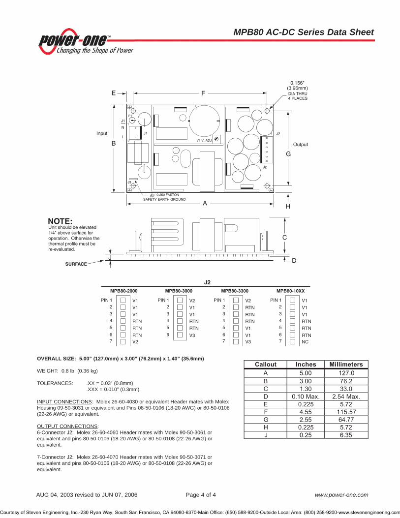
N
LV1 V. ADJ.
Output
0.156"(3.96mm)
A
B
E F
G
H
C
DJ
J2
SAFETY EARTH GROUND: 0.250 FASTONJ3
Input
1
J3
J2
1
F1
2
J1
J1
DIA THRU4 PLACES
V1
V1
V1
RTN
RTN
RTNV2
PIN 12
3
4
5
67
V2
RTN
RTN
RTN
V1
V1V3
PIN 12
3
4
5
67
V1
V1
V1
RTN
RTN
RTNNC
PIN 1
MPB80-2000
SURFACE
MPB80-3000 MPB80-3300
J2MPB80-10XX
2
3
4
5
67
V2
V1
V1
RTN
RTN
V3
PIN 12
3
4
5
6
Unit should be elevated 1/4" above surface for operation. Otherwise the thermal profile must be re-evaluated.
NOTE:
OVERALL SIZE: 5.00” (127.0mm) x 3.00” (76.2mm) x 1.40” (35.6mm)
WEIGHT: 0.8 lb (0.36 kg)
TOLERANCES: .XX = 0.03” (0.8mm).XXX = 0.010” (0.3mm)
INPUT CONNECTIONS: Molex 26-60-4030 or equivalent Header mates with MolexHousing 09-50-3031 or equivalent and Pins 08-50-0106 (18-20 AWG) or 80-50-0108(22-26 AWG) or equivalent.
OUTPUT CONNECTIONS:6-Connector J2: Molex 26-60-4060 Header mates with Molex 90-50-3061 orequivalent and pins 80-50-0106 (18-20 AWG) or 80-50-0108 (22-26 AWG) orequivalent.
7-Connector J2: Molex 26-60-4070 Header mates with Molex 90-50-3071 orequivalent and pins 80-50-0106 (18-20 AWG) or 80-50-0108 (22-26 AWG) orequivalent.
Callout Inches Millimeters
A 5.00 127.0
B 3.00 76.2
C 1.30 33.0
D 0.10 Max. 2.54 Max.
E 0.225 5.72
F 4.55 115.57
G 2.55 64.77
H 0.225 5.72
J 0.25 6.35
MPB80 AC-DC Series Data Sheet
AUG 04, 2003 revised to JUN 07, 2006 Page 4 of 4 www.power-one.com
Courtesy of Steven Engineering, Inc.-230 Ryan Way, South San Francisco, CA 94080-6370-Main Office: (650) 588-9200-Outside Local Area: (800) 258-9200-www.stevenengineering.com

Multiple-Output Model Selection – 240W WITH 300 LFM FORCED AIR COOLING
MODEL OUTPUT ADJUSTMENT OUTPUT LINE LOAD RIPPLE & NOISE INITIAL SETTINGVOLTAGE RANGE CURRENT (NOTE 1) REGULATION REGULATION Pk-Pk (NOTE 2) ACCURACY
+3.3V +0.5V 50A 0.2% 1% 50mV ± 30mV
NET1-4350 +12V FIXED 4A 0.2% 3% 120mV ± 100mV
+12V FIXED 4A 0.2% 3% 120mV ± 100mV
+5V +0.5V 30A 0.2% 1% 50mV ± 50mV
+3.3V +0.5V 50A 0.2% 1% 50mV ± 20mV
NET1-4230 +5V FIXED 5A 0.2% 3% 50mV ± 50mV
+12V FIXED 4A 0.2% 3% 120mV ± 100mV
+2.5V +0.5V 50A 0.2% 1% 50mV ± 20mV
+3.3V +0.5V 50A 0.2% 1% 50mV ± 30mV
NET1-4130 +5V FIXED 5A 0.2% 3% 50mV ± 50mV
+12V FIXED 4A 0.2% 3% 120mV ± 100mV
+1.8V +0.5V 50A 0.2% 1% 50mV ± 20mV
+1.8V +0.5V 50A 0.2% 1% 50mV ± 20mV
NET1-4112 +12V FIXED 4A 0.2% 3% 120mV ± 100mV
+12V FIXED 4A 0.2% 3% 120mV ± 100mV
+1.5V +0.5V 50A 0.2% 1% 50mV ± 20mVNOTES: 1) Output currents ratings are expressed with 300 LFM forced air @ 18 CFM.
2) Maximum peak-to-peak noise for a 20 MHz bandwidth.
NET1 AC-DC Series Data Sheet
MCD10011 Rev. 1.0 Page 1 of 4 www.power-one.com
Designed to meet the stringent requirements of today’s high-speed datacom and telecom circuitry, Power-One’s NET1Series is an excellent compact power solution for low-voltage, high-current applications. The NET1’s high efficiency isachieved through the use of synchronous rectification and a newly-patented “Soft Transition Forward Converter”.
The NET1’s rectification method lowers output losses, reduces system cooling requirements (allowing greater powerin a smaller package), and eliminates minimum-load requirements.
Advanced surface-mount design and packing technology reduce the NET1’s height to 1.35” (34.3mm) to fit in 1Uapplications. NET1’s high-performance active power factor circuitry meets EN61000-3-2 requirements for compliancewith European Power Line Harmonic Requirements for 2001. A multifunctional output terminal allows connection to #8ring lugs, 0.25” quick disconnects, cable connectors, and PCB-mounted connectors.
Description
Model numbers highlighted in yellow or shaded are not recommended for new designs.
Features• RoHS lead-solder exemption• Currents over 100 Amps• Fits 1U chassis height constraints• No minimum load requirement• Current-share capabilities on all outputs• Patented high-efficiency design• Meets European power factor requirements• Excellent load transient response
Courtesy of Steven Engineering, Inc.-230 Ryan Way, South San Francisco, CA 94080-6370-Main Office: (650) 588-9200-Outside Local Area: (800) 258-9200-www.stevenengineering.com

NET1 AC-DC Series Data Sheet
MCD10011 Rev. 1.0 Page 2 of 4 www.power-one.com
Input SpecificationsPARAMETER CONDITIONS/DESCRIPTION MIN TYP MAX UNITS
Input Voltage - AC Continuous input range. 85 264 VACInput Frequency AC input. 47 63 HzHold-up Time After last AC line peak at 240 watts. 20 ms Input Current 85 VAC at full rated load. 4.0 ARMS
Input Protection Non-user serviceable internally located AC input line fuse. Inrush Surge Current Internally limited by thermistor. Vin = 220 VAC, one cycle, 25 °C. 35 APK
Power Factor Per EN61000-3-2. 0.95 W/VA
Output SpecificationsPARAMETER CONDITIONS/DESCRIPTION MIN TYP MAX UNITS
Efficiency Full Rated Load, 110 VAC. Varies with distribution of loads among outputs. 75 %Ripple and Noise Full load, 20 MHz bandwidth. See Model Selection ChartsOutput Power With 300 LFM forced air cooling. (Note 1) 240 WattsOvershoot / Undershoot Output voltage overshoot/undershoot at turn-on. 0 %Regulation Varies by output. Total regulation includes: line changes over the specified. See Model Selection Charts
input range, changes in load starting at 20% load and changing to 100% load. Transient Response Recovery time, to within 1% of initial set point due to a 10-100% load change, 500 µs
1% max. deviation. Turn-on Delay Time required for initial output voltage stabilization. 2 SecTurn-on Rise Time Time required for output voltage to rise from 10% to 90%. 20 ms
Interface Signals and Internal ProtectionPARAMETER CONDITIONS/DESCRIPTION MIN TYP MAX UNITS
Overvoltage Protection Overvoltage protection on all outputs. 120 140 %Unit latches off when overvoltage is detected.AC input must be recycled to reset.
Overload Protection Fully protected against output overload and short circuit. Automatic recovery upon removal of overload condition. All outputs are individually current limited.
Overtemperature Protection System shutdown due to excessive internal temperature, automatic reset. Output Good Signal indicates output good when at a TTL high state. If any of the outputs are
<14% or >14% of the nominal output voltage, then this signal will make atransition to a TTL low state. Pull-up resistance is 1k� to 5V Vcc and minimumsink current is 50 mA. Maximum voltage at low state is 0.5 V.
Input Power Fail Warning TTL-compatible signal. Pull-up resistance is 1k� to 5V Vcc and minimumsink current is 50 mA. Maximum voltage at low state is 0.5 V. Time before regulation 5 msdropout due to loss of input power. May be used as independent PSOK signal in redundant applications.
Current Share Available on all outputs. Accuracy of shared current with up to 6 parallel units. 10 %Single wire current share. Isolation diodes need to be added for parallel configurationswith or without redundancy.
Remote Sense Available on all outputs. Total voltage compensation for cable losses with 500 mVrespect to the main output.
NOTES: 1) Output current ratings are expressed with 300 LFM forced air @ 18 CFM.
Courtesy of Steven Engineering, Inc.-230 Ryan Way, South San Francisco, CA 94080-6370-Main Office: (650) 588-9200-Outside Local Area: (800) 258-9200-www.stevenengineering.com

NET1 AC-DC Series Data Sheet
MCD10011 Rev. 1.0 Page 3 of 4 www.power-one.com
Safety, Regulatory, and EMI SpecificationsPARAMETER CONDITIONS/DESCRIPTION MIN TYP MAX UNITS
Agency Approvals UL60950.CSA 22.2 NO. 60950-00 (cUL). ApprovedEN60950 (TÜV).
Dielectric Withstand Voltage Input to output per EN60950. 2600 VDC Electromagnetic Interference FCC CFR title 47 Part 15 Sub-Part B - Conducted. B Class
EN55022 / CISPR 22 Conducted. BESD Susceptibility Per EN61000-4-2, level 4. 8 kVRadiated Susceptibility Per EN61000-4-3, level 3. 10 V/MEFT/Burst Per EN61000-4-4, level 3. ±2 kVInput Transient Protection Per EN61000-4-5, class 3. Line to Line 1 kV
Line to Ground 2Insulation Resistance Input to output. 10 M�
Environmental SpecificationsPARAMETER CONDITIONS/DESCRIPTION MIN TYP MAX UNITS
Altitude Operating. 10k ASL Ft.Non-Operating. 40k ASL Ft.
Operating Temperature At 100% load 0 50 °CStorage Temperature -40 85 °CTemperature Coefficient 0 °C to 70 °C (after 15-minute warmup). ±0.02 ±0.05 %/°CRelative Humidity Non-Condensing. 5 95 %RHShock Peak acceleration. 20 GPK
Vibration Random vibration, 10 Hz to 2 kHz, 3 axis. 6 GRMS
MechanicalDESCRIPTION NOTES SIZE IMPACT
Metric Mounting M4 x 0.7 mounting inserts: 2 mounting surfaces Size 7.00" x 4.50" x 1.35"
(177.8mm x 114.3mm x 34.3mm)
NUCLEAR AND MEDICAL APPLICATIONS - Power-One products are not designed, intended for use in, or authorized for use as critical componentsin life support systems, equipment used in hazardous environments, or nuclear control systems without the express written consent of the respectivedivisional president of Power-One, Inc.
TECHNICAL REVISIONS - The appearance of products, including safety agency certifications pictured on labels, may change depending on thedate manufactured. Specifications are subject to change without notice.
Courtesy of Steven Engineering, Inc.-230 Ryan Way, South San Francisco, CA 94080-6370-Main Office: (650) 588-9200-Outside Local Area: (800) 258-9200-www.stevenengineering.com
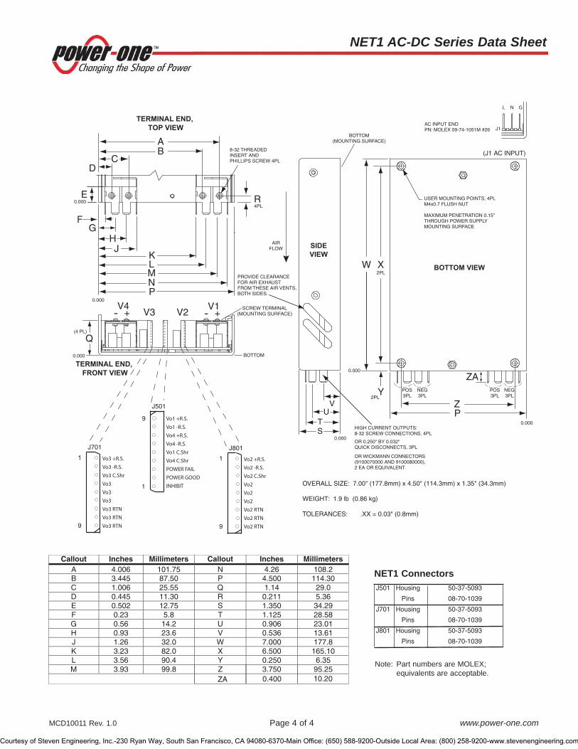
NET1 AC-DC Series Data Sheet
MCD10011 Rev. 1.0 Page 4 of 4 www.power-one.com
J501 Housing 50-37-5093
Pins 08-70-1039
J701 Housing 50-37-5093
Pins 08-70-1039
J801 Housing 50-37-5093
Pins 08-70-1039
BOTTOM VIEW
SIDE
VIEW
TERMINAL END,
TOP VIEW
X
Z
ZA
Y
PV
E
D
R
UTS
P
V4V3- +
V1- +
NML
AB
KJ
C
HG
F
W
USER MOUNTING POINTS, 4PLM4x0.7 FLUSH NUT
MAXIMUM PENETRATION 0.15"THROUGH POWER SUPPLYMOUNTING SURFACE
PROVIDE CLEARANCE FOR AIR EXHAUST FROM THESE AIR VENTS,BOTH SIDES.
8-32 THREADEDINSERT ANDPHILLIPS SCREW 4PL
BOTTOM(MOUNTING SURFACE)
AIRFLOW
4PL
2PL
2PL
POS3PL
POS3PL
NEG3PL
NEG3PL
0.000
0.000
0.000HIGH CURRENT OUTPUTS:8-32 SCREW CONNECTIONS, 4PL
OR 0.250" BY 0.032" QUICK DISCONNECTS, 3PL
OR WICKMANN CONNECTORS(9100070000 AND 9100080000), 2 EA OR EQUIVALENT.
TERMINAL END,
FRONT VIEW
Q
0.000
0.000
0.000
(4 PL)
SCREW TERMINAL(MOUNTING SURFACE)
BOTTOM
V2
(J1 AC INPUT)
J1
GNL
AC INPUT ENDPN: MOLEX 09-74-1051M #26
1
J801
9
1
J501
9
1
J701
9
Vo3 +R.S.
Vo3 -R.S.
Vo3 C.Shr
Vo3
Vo3
Vo3
Vo3 RTN
Vo3 RTN
Vo3 RTN
Vo2 +R.S.
Vo2 -R.S.
Vo2 C.Shr
Vo2
Vo2
Vo2
Vo2 RTN
Vo2 RTN
Vo2 RTN
Vo1 +R.S.
Vo1 -R.S.
Vo4 +R.S.
Vo4 -R.S.
Vo1 C.Shr
Vo4 C.Shr
POWER FAIL
POWER GOOD
INHIBIT OVERALL SIZE: 7.00" (177.8mm) x 4.50" (114.3mm) x 1.35" (34.3mm)
WEIGHT: 1.9 lb (0.86 kg)
TOLERANCES: .XX = 0.03" (0.8mm)
Callout Inches Millimeters Callout Inches MillimetersA 4.006 101.75 N 4.26 108.2B 3.445 87.50 P 4.500 114.30C 1.006 25.55 Q 1.14 29.0D 0.445 11.30 R 0.211 5.36E 0.502 12.75 S 1.350 34.29F 0.23 5.8 T 1.125 28.58G 0.56 14.2 U 0.906 23.01H 0.93 23.6 V 0.536 13.61J 1.26 32.0 W 7.000 177.8K 3.23 82.0 X 6.500 165.10L 3.56 90.4 Y 0.250 6.35M 3.93 99.8 Z
ZA3.7500.400 10.20
95.25
NET1 Connectors
Note: Part numbers are MOLEX;equivalents are acceptable.
Courtesy of Steven Engineering, Inc.-230 Ryan Way, South San Francisco, CA 94080-6370-Main Office: (650) 588-9200-Outside Local Area: (800) 258-9200-www.stevenengineering.com

NET2 AC-DC Series Data Sheet
MCD10012 Rev. 1.0, 23-Aug-07 Page 1 of 5 www.power-one.com
Features• RoHS lead-solder exemption• 400W output power with currents over 100 Amps• 85% efficiency (typical)• 5-output construction• Isolated V2 and V3 outputs• Standby output of 5V @ 2A• Fits 1U chassis height constraints• No minimum load requirement• Active current-share capabilities with redundant
capabilities on the four main outputs• Patented high-efficiency design• Meets European power factor requirements• Excellent load transient response• Redundancy without use of ORing diode
Multiple-Output Model Selection – 400W WITH 460 LFM FORCED-AIR COOLING
MODEL OUTPUT ADJUSTMENT OUTPUT LINE LOAD & CROSS- RIPPLE & NOISE INITIAL SETTINGVOLTAGE RANGE CURRENT REGULATION REGULATION Pk-Pk (NOTE 2) ACCURACY (NOTE 3)
V1 +3.3V +5%, -2% 55A 0.6% 1% 50mV +40mV, -10mV
NET2-4350 (Note1) V2 12V +5%, -5% 5A 0.5% 1% 120mV ± 70mV
V3 12V +5%, -5% 5A 0.5% 1% 120mV ± 70mV
V4 +5V +5%, -2% 40A 0.5% 1% 50mV +50mV, -10mV
V5 +5.2VSB FIXED 2A 0.5% 4% 50mV ± 110mV
V1 +3.3V +5%, -2% 55A 0.6% 1% 50mV +40mV, -10mV
NET2-4231 (Note1,4) V2 12V +5%, -5% 5A 0.5% 1% 120mV ± 70mV
V3 1.8V +5%, -2% 15A 0.6% 1% 120mV ± 70mV
V4 +2.5V +5%, -2% 55A 0.6% 1% 50mV +30mV, -10mV
V5 +5.2VSB FIXED 2A 0.5% 4% 50mV ± 110mV
NOTES: 1) V1 + V2, or V3 + V4 must not exceed 200W.2) Maximum peak-to-peak noise for a 20 MHz bandwidth.3) Initial set points: V1 @ 40A, V2 @ 4A, V3 @ 4A, V4 @ 30A, and V5 @ 1A.4) Consult factory for availability.
Designed to meet the stringent requirements of today’s high-speed circuitry, Power-One’s NET2 Series is an excellentcompact power solution for low-voltage, high-current applications. The NET2’s high efficiency is achieved through theuse of synchronous rectification and a newly-patented “Soft Transition Forward Converter”.
The NET2’s rectification method lowers output losses, reduces system cooling requirements (allowing greater powerin a smaller package), and eliminates minimum-load requirements.
Advanced surface-mount design and packing technology reduce the NET2’s height to 1.59” (40.3mm) to fit in 1Uapplications. NET2’s high-performance active power factor circuitry meets EN61000-3-2 requirements for compliancewith European Power Line Harmonic Requirements for 2001. A multifunctional output terminal allows connection to #8ring lugs, 0.25” quick disconnects, cable connectors, and PCB-mounted connectors.
Description
Advance Product Release
Courtesy of Steven Engineering, Inc.-230 Ryan Way, South San Francisco, CA 94080-6370-Main Office: (650) 588-9200-Outside Local Area: (800) 258-9200-www.stevenengineering.com

NET2 AC-DC Series Data Sheet
MCD10012 Rev. 1.0, 23-Aug-07 Page 2 of 5 www.power-one.com
Input SpecificationsPARAMETER CONDITIONS/DESCRIPTION MIN TYP MAX UNITS
Input Voltage - AC Continuous input range. 85 264 VACInput Frequency AC input. 47 63 HzHold-up Time After last AC line peak at 400 watts. 20 msInput Current 85 VAC at full rated load. 7.0 ARMS
Input Protection Non-user serviceable internally located AC input line fuse. Inrush Surge Current Internally limited by thermistor. Vin = 220 VAC, one cycle, 25°C. 35 APK
Power Factor Per EN61000-3-2 (Over the entire input range and above 60W load). 0.95 W/VA
Output SpecificationsPARAMETER CONDITIONS/DESCRIPTION MIN TYP MAX UNITS
Efficiency Full Rated Load, 115 VAC. Varies with distribution of loads among outputs. 85 %Ripple and Noise Full load, 20 MHz bandwidth. See Model Selection ChartsOutput Power With 460 LFM forced-air cooling (25 CFM through the power supply opening),
V1+V2+V3+V4+V5: 400 WattsV1+V2 or V3+V4: 200
Overshoot / Undershoot Output voltage overshoot/undershoot at turn-on. 3.5 %Regulation Varies by output. Regulation includes: line changes over the specified See Model Selection Charts
input range and changes in load between 0% and 100% load.Transient Response Recovery time, to within 1% of initial set point due to a 50% load change in V1/V4/V5: 1 ms
the load range of 10 to 100%; 3.5% or 100mV deviation, whichever is greater. V2/V3 0.5Turn-on Delay Time required for initial output voltage stabilization. 1.5 2 SecTurn-on Rise Time Time required for output voltage to rise from 10% to 90%. 20 ms
Interface Signals and Internal ProtectionPARAMETER CONDITIONS/DESCRIPTION MIN TYP MAX UNITS
Overvoltage Protection Overvoltage protection on all outputs except V5. 120 140 %Unit latches off when overvoltage is detected.AC input must be recycled to reset. V5 is protected by a 6.2V ±5%, 2W Zener diode.
Overload Protection Fully protected against output overload and short circuit. Automatic recovery upon removal of overload condition. All outputs are individually current limited.
Overtemperature Protection Power supply shuts down due to excessive internal overtemperature at the outputconverter’s primary switching transistors. Power supply resets automatically uponremoval of the overtemperature cause.
Output Good TTL-compatible global Output Good signal. The signal is active when any of the V1-V4 outputs drop >14% below nominal. Source impedance is 1k�.
Input Power Fail Warning Open collector signal. Time before regulation dropout due to loss of input 5 mspower. May be used as independent PSOK signal in redundant applications.
Current Share Available on all outputs except V5. Accuracy of shared current with up 10 %to two parallel units. Single wire current share is provided. For parallelingmore than two units, consult factory.
Remote Sense Available on all outputs except V5. Total voltage compensation for cable losses with 500 mVrespect to the main output.
Courtesy of Steven Engineering, Inc.-230 Ryan Way, South San Francisco, CA 94080-6370-Main Office: (650) 588-9200-Outside Local Area: (800) 258-9200-www.stevenengineering.com

NET2 AC-DC Series Data Sheet
MCD10012 Rev. 1.0, 23-Aug-07 Page 3 of 5 www.power-one.com
Safety, Regulatory, and EMI SpecificationsPARAMETER CONDITIONS/DESCRIPTION MIN TYP MAX UNITS
Agency Approvals UL60950. NET2-4350 Approved; NET2-4231 PendingCSA 22.2, NO. 60950-00 (cUL). NET2-4350 Approved; NET2-4231 PendingEN60950-1 (TÜV). NET2-4350 Approved; NET2-4231 PendingIEC60950-1 NET2-4350 Approved; NET2-4231 Pending
Dielectric Withstand Voltage Input to output per EN60950. 2600 VDC Electromagnetic Interference FCC CFR title 47 Part 15 Sub-Part B - Conducted. B Class
EN55022 / CISPR 22 Conducted. BESD Susceptibility Per EN61000-4-2, level 4. Contact discharge: ±10% 8 kV
Air discharge: 10Radiated Susceptibility Per EN61000-4-3, level 3. Frequency 0.8 - 1.0 GHz, 80% AM @ 1 kHz 10 V/MEFT/Burst Per EN61000-4-4, level 3. ±2 kVInput Transient Protection Per EN61000-4-5, class 3. Line to Line 1 kV
Line to Ground 2Ground Leakage UL60950/EN60950/CSA 6950-00 @254VAC 1 mA
Environmental SpecificationsPARAMETER CONDITIONS/DESCRIPTION MIN TYP MAX UNITS
Altitude Operating. 10k ASL Ft.Non-Operating. 40k ASL Ft.
Operating Temperature From 50°C to 70°C derate each output and total power At 100% load 0 50 °Cto 50% of rating at 70°C.
Storage Temperature -40 85 °CTemperature Coefficient 0°C to 70°C (after 15-minute warmup). ± 0.02 ± 0.05 %/°CRelative Humidity Non-Condensing. 5 95 %RHShock Operating: Half-sine, 10 ± 3ms duration; one positive and 10 20 GPK
one negative shock in each of the three perpendicular axesfor a total of 6 shocks.
Non-Operating: Half-sine, 10 ± 3ms duration; one positive 30 40 GPK
AND one negative shock in each of the three perpendicularaxes for a total of 6 shocks.
Vibration Operating: Logarithmic sweep, 1 octave/min 5-2000-5 Hzvertical, lateral, and longitudinal axes;5-32 Hz, 0.02” double amplitude;32-2000 Hz 1 Gpk2000-32 Hz 1 Gpk32-5 Hz double amplitude.
Non-Operating: Random 1 hour/axis, vertical, lateral, and 6.15 Grmsmax longitudinal over 10-2000 Hz.
MechanicalDESCRIPTION NOTES SIZE IMPACT
Metric Mounting M3 x 0.5 mounting inserts: 3 mounting surfaces Chassis Size 8.25" x 4.50" x 1.59"
(209.6mm x 114.3mm x 40.4mm)
Courtesy of Steven Engineering, Inc.-230 Ryan Way, South San Francisco, CA 94080-6370-Main Office: (650) 588-9200-Outside Local Area: (800) 258-9200-www.stevenengineering.com

NET2 AC-DC Series Data Sheet
MCD10012 Rev. 1.0, 23-Aug-07 Page 4 of 5 www.power-one.com
BOTTOM VIEW
1.588"
(40.3)
M3 X 0.5 MOUNTING INSERTS (8) PLACES,
2 PL EACH SIDE, 4PL ON BOTTOM.
0.150" MAX PROTRUSION OF
MOUNTING SCREWS INTO POWER SUPPLY.
0.700"
(17.8)
0.375"
(9.5)
0.250"
(6.4)
-1.100"
(-27.9)
2.100"
(53.3)
7.600"
(193)
- 0.900"
(-22.9)
8.000"
(203.2)
4.125"
(104.8)
4.500"
(114.3)
0.550"
(14)
7.600"
(193.0)
0.900"
(22.9)
0.370"
(9.4)
0.331"
(8.4)
0.331"
(8.4)
0.331"
(8.4)
0.331"
(8.4)
0.219"
(5.6)
0.400"
(10.2)
8.250"
(209.6)
0
0
0
0
0
0
MM
M
M M
M
M
M
± 0.020
NOTE: TOLERANCE ( .XXX = ± 0.010 UNLESS OTHERWISE SPECIFIED)
NOTE: METRIC DIMENSIONS ARE SHOWN IN BRACKETS
+ 0.000
- 0.020
HIGH CURRENT OUTPUTS
0.25" QUICK DISCONNECT, 12 PL MAX OR
#8 LUG 4PL, OR
WICKMAN CONNECTOR PN: 9100080000 OR EQUIV, 4 PL
Mechanical Drawing
Courtesy of Steven Engineering, Inc.-230 Ryan Way, South San Francisco, CA 94080-6370-Main Office: (650) 588-9200-Outside Local Area: (800) 258-9200-www.stevenengineering.com

NET2 AC-DC Series Data Sheet
MCD10012 Rev. 1.0, 23-Aug-07 Page 5 of 5 www.power-one.com
NET2-4350NET2-4231
P1 Housing 50-37-5113
Pins 08-70-1039
P2 Housing 50-37-5043
& P4 Pins 08-70-1039
P3 Housing 39-01-4041
& P5 Pins 39-00-0038
INPUT & OUTPUTS
Vo3 OUTPUT PINOUT SEC.CNTL.BRD.PINOUT Vo2 OUTPUT PINOUT
L
N
G
SEC.CNTL, Vo5
Vo2 O/P
Vo1
Vo1 RTN
Vo3 O/P
Vo4
Vo4 RTN
J6
J1
Vo1 adj
Vo3 adj
Vo4 adj
Vo2 adj
Vo3 Inhibit Vo2 Inhibit
Vo1 +R.S.
Vo1 -R.S.
Vo2 -R.S.
Vo4 +R.S.
Vo2 +R.S.
Vo4 -R.S.Vo3 C.Shr. Vo2 C.Shr.
Vo1 C.Shr.
Vo4 C.Shr.
POWER FAIL
POWER GOOD
INHIBIT
+Vo5
-Vo5
Vo3 -R.S.
Vo3 +R.S.
Vo3 RTN
Vo3 RTN
Vo3
Vo3
Vo2 RTN
Vo2 RTN
Vo2
Vo2
P5
P4
P1
P2
P3
Connectors
The NET2 uses #8-32 screw terminal and/or 0.25” faston connections for outputs 1 and 4, and Molex 5264-N Seriesconnectors (50-37-5093) for auxiliary outputs and control signals. For the AC input, the NET2 uses a Molex41694/2139 (09-50-3051) series connector.
NUCLEAR AND MEDICAL APPLICATIONS - Power-One products are not designed, intended for use in, or authorized for use as critical componentsin life support systems, equipment used in hazardous environments, or nuclear control systems without the express written consent of the respectivedivisional president of Power-One, Inc.
TECHNICAL REVISIONS - The appearance of products, including safety agency certifications pictured on labels, may change depending on thedate manufactured. Specifications are subject to change without notice.
NOTE: Part numbers are MOLEX; equivalents are acceptable.
Courtesy of Steven Engineering, Inc.-230 Ryan Way, South San Francisco, CA 94080-6370-Main Office: (650) 588-9200-Outside Local Area: (800) 258-9200-www.stevenengineering.com

Features• Single-phase AC input• 3U height• Active current share• Power Factor Correction (PFC)
Meets EN61000-3-2• Remote voltage adjust, and current monitoring• Overtemperature, overload, and overvoltage
protection• Power supply status indicators• Output current meter (bar graph)• MTBF> 700,000 hours
NHC3000 AC-DC Series Data Sheet
JUN 03, 2004 revised to MAY 26, 2006 Page 1 of 4 www.power-one.com
The NHC3000 Series of chassis-mounted power systems provides AC front-end capability to telecom, datacommunications and other distributed power designs. The NHC3000 can also be used for many other applicationsrequiring bulk power.NHC3000 power supplies provide excellent protection against input voltage transients. A connector at the rear of thesupply provides access to interfaces for remote sensing, remote voltage adjust, current sharing, power supply status,standby logic voltage, remote on/off, and power connections.Airflow for the NHC3000 is from the front through the rear. The output is floating with respect to the chassis and maybe used as a positive or negative polarity supply.
Description
Model SelectionMODEL OUTPUT ADJUSTMENT MAXIMUM OUTPUT LINE LOAD RIPPLE & NOISE INITIAL SETTING
VOLTAGE RANGE CURRENT REGULATION REGULATION (NOTE 1) %p-p (NOTE 2) ACCURACY
NHC3011-5 24V 21.6V to 26.4V 125A 0.2% 0.4% 1% 23.95V to 24.05VNHC3011-6 28V 25.2V to 30.8V 107A 0.2% 0.4% 1% 27.92V to 28.08VNHC3021-8 48V 43.2V to 52.8V 62.5A 0.2% 0.4% 1% 47.90V to 48.10V
NOTES: 1) With Remote Sense connected.2) Maximum peak-to-peak noise expressed as a percentage of output voltage, 20 MHz bandwidth.
Input SpecificationsPARAMETER CONDITIONS/DESCRIPTION MIN NOM MAX UNITS
Input Voltage - AC Single-phase continuous input range. 180 264 VACInput Frequency AC input. 47 63 HzHold-up Time AC turn-off to output greater than or equal to 95%. 16 msInput Current At full rated load per module. at 230 VAC 15.0 ARMS
Inrush Surge Current 30 APK
Power Factor Per EN61000-3-2 at full load. 0.99 W/VAAt half load. 0.98
Operating Frequency Switching frequency 140 kHz
Courtesy of Steven Engineering, Inc.-230 Ryan Way, South San Francisco, CA 94080-6370-Main Office: (650) 588-9200-Outside Local Area: (800) 258-9200-www.stevenengineering.com

Output SpecificationsPARAMETER CONDITIONS/DESCRIPTION MIN NOM MAX UNITS
Efficiency Full rated load. 88 %Minimum Loads Minimum loading required to maintain regulation. 0 AOutput Power Per module. 3000 WattsOvershoot / Undershoot Output voltage overshoot/undershoot at turn-on. ±3.0 %Transient Response Maximum recovery time, to within 1% of initial set point due to a 500 µs
50-100-50% load change, 1A/µs, ±3.0% max. deviation.Turn-On Delay Time AC turn-on to output >95%. 1.2 2.0 SecTurn-on Rise Time Time required for output voltage to rise from 10% to 90%. 100 ms
Interface Signals and Internal ProtectionPARAMETER CONDITIONS/DESCRIPTION MIN NOM MAX UNITS
Overvoltage Protection Latch style overvoltage protection. 24V model 26.4 27.628V model 30.8 33.8 V48V model 52.8 55.2
Overcurrent Protection Constant current limit, as a percentage of maximum rated load. 100 105 110 %Short Circuit Protection Short circuit current, as a percentage of maximum rated load. 110 %
Output recovers automatically after removal of short.Overtemperature Module shuts down when internal temperature reaches an unsafe level.DC OK, Output Good (Module) Output low threshold measured at output studs. Form C contacts, ±2 ±5 ±8 %
rating is 500 mA at 30 VDC.Input Power Fail Warning Relay closes >5 ms before output drops to <95%. Relay opens after 5 ms
output is in regulation. Form C contacts, pull-up to +5 V through a1 k� resistor.
Current Monitor Signal provides an output of 0-10V which appliesover 10-100% of rated load. At 50% load: 4.5 5.5 VDC
Current Share Accuracy Applies over 10-100% load as a percentage of full load. ±5 %Remote Sense Total voltage compensation for cable losses with respect to the main output. 0.5 VAuxiliary Power (Logic Power) Referenced to negative output terminal and derived from the internal 5.1 VDC. 50 mAOutput Margin Margin High - Connect Margin input to Margin Ref. +5
%Margin Low - Connect Margin input to Logic Common. -5Power Fail Signal PF drops to “0” before output drops to 95% due to loss of AC.
& PF Warning Time PF goes to “1” (logic high) after +5 V is in regulation. Form C Warning Time: 5 mscontacts pull up to +5 V through a 1 k� resistor.
Output Voltage and Optional - Consult factory for details..Current Programming
Mechanical SpecificationsPARAMETER CONDITIONS/DESCRIPTION MIN NOM MAX UNITS
Input Connector Terminal block.Output Connector Copper bus bar blade with single round hole for 5/16 screw.Signal Connector J1 Power-One P/N 10X0172-001, Amp 247846-4, ITT Common ZEDBL25SBA
Mates with Power=One P/N 10X0105-000, Amp 202208-1, ITT Common DBA25-K87-F0Mating Pin P/N 12X0005-000, Amp 66506-8
Visual Indicators AC-OK LED and DC-OK LED located on the connector end of the supply.Cooling Internal fan; approximately 100 CFM.Mounting See outline drawing.
NHC3000 AC-DC Series Data Sheet
JUN 03, 2004 revised to MAY 26, 2006 Page 2 of 4 www.power-one.com
Courtesy of Steven Engineering, Inc.-230 Ryan Way, South San Francisco, CA 94080-6370-Main Office: (650) 588-9200-Outside Local Area: (800) 258-9200-www.stevenengineering.com

Safety, Regulatory, and EMI SpecificationsPARAMETER CONDITIONS/DESCRIPTION MIN NOM MAX UNITS
Agency Approvals UL 60950-1 (UL), CSA C22.2 No. 60950-1, EN60950-1 (TÜV), CE Mark, and CB ReportElectromagnetic Interference FCC CFR title 47 Part 15 Sub-Part B. A
Conducted & Radiated EN55022 / CISPR 22. A Class
ESD Susceptibility Per EN61000-4-2, level 3, direct discharge. 8 kVPer EN61000-4-2, level 3, air discharge. 15
Radiated Susceptibility Per EN61000-4-3, level 3. 10 V/mEFT/Burst Per EN61000-4-4, level 3, @ 5 kHz. 2 kVInput Transient Protection Per EN61000-4-5, level 3. Line to Line 2 kVConducted Susceptibility Per EN61000-4-6, level 3; 10V from 150 Hz to 80 MHz.Leakage Current Per EN60950. at 240 VAC 1.5 mA
Environmental SpecificationsPARAMETER CONDITIONS/DESCRIPTION MIN NOM MAX UNITS
Storage Temperature -40 85 °COperating Temperature Derate linearly to 60% at 70 °C 0 50 °CTemperature Coefficient After 15-minute warmup. 0.008 %/°CHumidity, Non-Condensing 5 95 %Altitude Derate at 7°C/1000 ft above 8000 ft. 13,000 ftShock Operating: half-sine 10 ms, 3 axis. +20 GPK
Non-operating: half-sine 10 ms, 3 axis. +40Vibration Operating: swept sine 5-2000-5 Hz, 5-32 Hz, 0.02îDA, 32-2000 Hz. 1 GPK
Non-operating: random 10-2000 Hz. 6.15 GrmsAcoustics Sound pressure level at 1 meter. 57 dbAWeight 12.1 lb
5.49 kg
NHC3000 AC-DC Series Data Sheet
JUN 03, 2004 revised to MAY 26, 2006 Page 3 of 4 www.power-one.com
NUCLEAR AND MEDICAL APPLICATIONS - Power-One products are not designed, intended for use in, or authorized for use as critical componentsin life support systems, equipment used in hazardous environments, or nuclear control systems without the express written consent of the respectivedivisional president of Power-One, Inc.
TECHNICAL REVISIONS - The appearance of products, including safety agency certifications pictured on labels, may change depending on thedate manufactured. Specifications are subject to change without notice.
Courtesy of Steven Engineering, Inc.-230 Ryan Way, South San Francisco, CA 94080-6370-Main Office: (650) 588-9200-Outside Local Area: (800) 258-9200-www.stevenengineering.com

A B D
EF
G
HK
M
N
R
S
T
U
V W
P
C
0.25"
J1
AIRFLOW DIRECTION
N
L
Callout Inches Millimeters
A 12.25 311.2
B 1.50 38.1
C 0.12 3.1
D 5.00 127.0
E 5.00
F 3.98 101.1
G 2.86 72.6
H 0.49 12.5
K 1.17 29.7
M 2.19 55.6
N 1.36 34.5
P 2.16 54.9
R Ø 0.34 Ø 8.6
S 0.80 20.3
T 0.650 16.51
U 3.700 93.98
V 0.825 21.0
W 9.425 239.4
127.0
Pin Description Pin Description
1 DC OK N/C 13 CURRENT SHARE
2 DC OK COM 14 +5V LOGIC
3 DC OK N/O 15 (-) SENSE
4 POWER FAIL PULL UP 16 (+) SENSE
5 ENABLE PULL UP 17 N/U
6 POWER FAIL 18 N/U
7 POWER FAIL RTN 19 I PROGRAM (OPTIONAL
8 REMOTE ON/OFF 20 LOGIC COM
9 REMOTE ON/OFF RTN 21 N/U
10 CURRENT MONITOR 22 N/U
11 MARGIN REF 23 N/U
12 MARGIN 24 N/U
25 RESERVED FOR OPTIONS
NHC3000 AC-DC Series Data Sheet
JUN 03, 2004 revised to MAY 26, 2006 Page 4 of 4 www.power-one.com
NHC3000 OVERALL SIZE: 12.25" x 5.00" x 5.00" (311.2mm x 127.0mm x 127.0mm)
J1 Connector Pinout
Courtesy of Steven Engineering, Inc.-230 Ryan Way, South San Francisco, CA 94080-6370-Main Office: (650) 588-9200-Outside Local Area: (800) 258-9200-www.stevenengineering.com

NRG Series The NRG Series has been discontinued. An overview of replacement mid-power AC-DC products is available at http://www.power-one.com/products/acdc_overview.html For schematics and repair information, a technical support contact form is available at: http://www.power-one.com/cgi-bin/start.cgi/dynamic/selector/emailtech.html
Courtesy of Steven Engineering, Inc.-230 Ryan Way, South San Francisco, CA 94080-6370-Main Office: (650) 588-9200-Outside Local Area: (800) 258-9200-www.stevenengineering.com

• RoHS lead solder exemption compliant • Power Factor Correction meets EN61000-3-2 (AC input
versions)• Fully-regulated outputs• Remote sense• Logic level Inhibit• Current Share, Power Fail, and Power Good Signals• Overtemperature, overvoltage, and overcurrent protected• Available with metric or SAE mountings• Input transient & ESD compliance to
EN61000-4-2/-3/-4/-5• Fan output voltage and optional fan• Optional isolation diodes for parallel or redundant
operation• DC input versions (36-75VDC)
PFC500 Input SpecificationsPARAMETER CONDITIONS/DESCRIPTION MIN NOM MAX UNITS
Input Voltage - AC Continuous input range. 85 264 VACInput Frequency AC Input. 47 63 HzBrown Out Protection Lowest AC input voltage that regulation is maintained with full rated loads. 85 VACHold-Up Time Over full AC input voltage range at full rated load. 20 msInput Current 85 VAC at full rated load. 7.8 ARMS
Input Protection Non-user serviceable internally located AC input line fuse, F10A, 250V.Inrush Surge Current Internally limited by thermistor, one cycle, 25°C. 110 VAC 35 APK
220 VAC 65Power Factor Per EN61000-3-2. 0.98 W/VAOperating Frequency Switching frequency of main transformer. 100 kHz
Single-Output Model SelectionMODEL OUTPUT ADJUSTMENT MAXIMUM OUTPUT LINE LOAD RIPPLE & NOISE INITIAL SETTING
VOLTAGE RANGE CURRENT (NOTE 3) REGULATION REGULATION (NOTE 4) %p-p (NOTE 5) ACCURACY
PFC500-1024/PDC500-1024D 24V 21.6V to 26.4V 21A 0.5% 0.2% 1% 23.88V to 24.12V(NOTE 1)
PFC500-1028 (NOTE 2) 28V 25.2V to 30.8V 17.9A 0.5% 0.2% 1% 27.86V to 28.14VPFC500-1048 (NOTE 2) 48V 46.0V to 56.0V 10.4A 0.5% 0.5% 1% 47.52V to 48.48VNOTES: 1) For AC input, use PFC500 prefix; use PDC500 prefix for DC input versions.
2) Consult factory for availability of 28V and 48V units with DC input.3) Output currents ratings are expressed with 300 LFM forced air.4) Remote sense connected. See Application Note #P1 for load regulation when using the D option for 24V units.5) Maximum peak to peak noise expressed as a percentage of output voltage, 20 MHz bandwidth.
For ripple/noise on “D” option models, see options data on page 3.
PFC500/PDC500 Series Data Sheet
AUG 01, 2003 revised to JUL 13, 2006 Page 1 of 4 www.power-one.com
The PFC500/PDC500 products of the PerFormanCe Power Series combine high performance midrange power withhigh power density (4.4 watts/in3) and high reliability to meet the requirements of communications, commercial, andindustrial systems.
Providing tightly regulated DC power, the PFC500/PDC500 delivers full output performance with only 300 Linear Feetper Minute (LFM) forced-air cooling (factory-installed fan optional). Main channel current sharing is provided forredundant applications, and AC input units can be paralleled with DC input versions. Units are available with SAEmountings or optional metric mountings.
The PFC500/PDC500 product line is approved to the latest international regulatory standards, and displays the CEMark.
Features
Description
Courtesy of Steven Engineering, Inc.-230 Ryan Way, South San Francisco, CA 94080-6370-Main Office: (650) 588-9200-Outside Local Area: (800) 258-9200-www.stevenengineering.com

PDC500 Input SpecificationsPARAMETER CONDITIONS/DESCRIPTION MIN NOM MAX UNITS
Input Voltage - DC Continuous input range. Full power at 42-75 VDC. 36 75 VDCDerate linearly from 40 VDC to 36 VDC, 400W.
Low Voltage Protection Lowest DC input voltage. 34 VDCHold-up Time At full load over DC input range. 17 msInput Current 48 VDC at full rated load. 14 ADCInput Protection Non-user serviceable internally located fuse. Inrush Surge Current Vin = 75 VDC, cold thermistor. TBD APK
Output Specifications (PFC500 and PDC500)PARAMETER CONDITIONS/DESCRIPTION MIN NOM MAX UNITS
Efficiency Full rated load, 110 VAC (PFC500)/ 48VDC (PDC500). 75 %Minimum loads PFC/PDC500-1024 0.6
PFC500-1028 0.6 AmpsPFC500-1048 1.2
Ripple and Noise Full load, 20 MHz bandwidth. See Model Selection ChartsOutput Power 300 LFM forced air cooling required for operation. See optional fan. 500 Watts
Continuous power, multiple output models. PDC500 requires derating below42 VDC; see PDC500 input specifications.
Overshoot / Undershoot Output voltage overshoot/undershoot at turn-on. 0 VRegulation Without connection of remote sense. PFC/PDC500-1024 0.8
PFC500-1028 0.7 %PFC500-1048 1.0
Transient Response Recovery time, to within 1% of initial set point due to a 50-100% load change, 1 ms3% max. deviation.
Turn-on Delay Time required for initial output voltage stabilization. 1 SecTurn-on Rise Time Time required for output voltage to rise from 10% to 90%. 10 ms
Interface Signals and Internal Protection (PFC500 and PDC500)PARAMETER CONDITIONS/DESCRIPTION MIN NOM MAX UNITS
Overvoltage Protection PFC/PDC500-1024 27.0 30.7PFC500-1028 32.0 35.0 VPFC500-1048 60.0 70.0
Overload Protection Fully protected against output overload and short circuit. Automatic recovery upon removal of overload condition.Overtemperature Protection System shutdown due to excessive internal temperature, automatic reset.Remote Sense Total voltage compensation for cable losses with respect to the main output. 250 mVCurrent Share Accuracy of shared current with up to 6 parallel units. 10 %Inhibit TTL compatible logic signal will inhibit outputs by the application of a logic low signal.
An open circuit or external TTL high signal allows normal operation.Input Power TTL compatible logic signal. Time before regulation dropout due to 4 msFail Warning loss of input power at 110 VAC.Power Good TTL compatible signal. Signal is low if main output is greater PFC/PDC500-1024 22.08 27.36
or less than 10% of nominal. For models without the PFC500-1028 25.20 30.80 V“D” option, internal pull-up resistor is 1k�� For “D” option, PFC500-1048 44.20 54.72pull-up resistor is 475�. See Apps Note #P1 for details.
Fan Voltage Provides 170mA current to user supplied fan if fan option is not selected. 12 V
PFC500/PDC500 Series Data Sheet
AUG 01, 2003 revised to JUL 13, 2006 Page 2 of 4 www.power-one.com
Courtesy of Steven Engineering, Inc.-230 Ryan Way, South San Francisco, CA 94080-6370-Main Office: (650) 588-9200-Outside Local Area: (800) 258-9200-www.stevenengineering.com

Safety, Regulatory, and EMI SpecificationsPARAMETER CONDITIONS/DESCRIPTION MIN NOM MAX UNITS
Agency Approvals UL1950. UL 60950 / CSA60950-00 (cULus Mark)Approved
EN60950 (TÜV). PDC500 (Pending).Dielectric Withstand Meets reinforced insulation of IEC60950.Electromagnetic Interference FCC CFR title 47 Part 15 Sub-Part B - Conducted. B Class
EN55022 / CISPR 22 Conducted. BESD Susceptibility Per EN61000-4-2, level 4. 8 kVRadiated Susceptibility Per EN61000-4-3, level 3. 10 V/MEFT/Burst (PFC500) Per EN61000-4-4, level 4. ±4 kVEFT/Burst (PDC500) Per EN61000-4-4, level 4. TBD kVInput Transient Protection PFC500 Per EN61000-4-5 class 3. PDC500 (class 2) Line to Line (PFC500) 1
Line to Ground (PFC500) 2kVLine to Line (PDC500) 0.5
Line to Ground (PDC500) 0.5Insulation Resistance Input to output. 10 M�
Leakage Current (PFC500) Per EN60950, 264 VAC. 2.0 mA
Environmental SpecificationsPARAMETER CONDITIONS/DESCRIPTION MIN NOM MAX UNITS
Altitude Operating. 10k ASL Ft.Non-Operating. 40k ASL Ft.
Operating Temperature At 100% load 0 50 °CDerate linearly above 50°C by 2.5% per °C. At 50% load 0 70 °C
Storage Temperature -55 85 °CForced Air Cooling Forced air cooling of 300 LFM (400 LFM for PDC500) is required if the internal
fan is not specified Cooling air velocity is measured at the output exiting window(2.5” x 5”). Airflow direction is from the input section to the output section.
Temperature Coefficient 0°C to 70°C (after 15 minute warm-up). ±0.02 ±0.05 %/°CRelative Humidity Non-Condensing. 5 95 %RHShock Operating: 10±3mSec, 3 axis, Half Sine. 20 G
Non-operating: 10±3mSec, 3 axis, Half Sine. 40Vibration Operating: 5-32Hz 0.02 in (DA)
32-2000Hz Sinusoidal 1 GPK
Non-operating: 6.15 GRMS
OptionsDESCRIPTION NOTES SIZE IMPACT
Isolation Diodes Add “D” as a suffix to the model number to order factory installed isolation diodes N/Afor parallel or redundant operation. For 24V models with the “D” option, external caps are required to meet the 1% noise/ripple spec. Power Good has a pull-upresistor of 475� on the 24V models. See Application Note #P1 for details.
Fan Add “F” as a suffix to the model number to order integral fan. 10.50" x 5.00" x 2.50"Fan provides the required 300 LFM (400 LFM for PDC500) of forced air cooling, (266.7mm x 127.0mm x 63.5mm)or otherwise provided by the end user.
Metric Mounting Add “M” as a suffix to the model number to order chassis with N/AM4 x 0.7 mounting inserts.
PFC500/PDC500 Series Data Sheet
AUG 01, 2003 revised to JUL 13, 2006 Page 3 of 4 www.power-one.com
Courtesy of Steven Engineering, Inc.-230 Ryan Way, South San Francisco, CA 94080-6370-Main Office: (650) 588-9200-Outside Local Area: (800) 258-9200-www.stevenengineering.com

Overall Size: 9.00" x 5.00" x 2.50" (228.6mm x 127.0mm x 63.5mm)Overall Length With Fan: 10.50" (266.7mm)
Weight: 4.3 lb (1.95 kg)
Input and Output Connections: 6-32 Screw Terminal on 0.375" (9.5mm) centers
Chassis: 0.090" (2.3mm) Aluminum Alloy, With Clear Finish
DC+ or
DC- or
SUGGESTED AIRFLOW *
* Airflow should be measured at the exiting window (5” x 2.5”).
PFC500/PDC500 Series Data Sheet
AUG 01, 2003 revised to JUL 13, 2006 Page 4 of 4 www.power-one.com
NUCLEAR AND MEDICAL APPLICATIONS - Power-One products are not designed, intended for use in, or authorized for use as criticalcomponents in life support systems, equipment used in hazardous environments, or nuclear control systems without the express written consent ofthe respective divisional president of Power-One, Inc.
TECHNICAL REVISIONS - The appearance of products, including safety agency certifications pictured on labels, may change depending on thedate manufactured. Specifications are subject to change without notice.
Courtesy of Steven Engineering, Inc.-230 Ryan Way, South San Francisco, CA 94080-6370-Main Office: (650) 588-9200-Outside Local Area: (800) 258-9200-www.stevenengineering.com

PFC250 AC-DC Series Data Sheet
MAY 26, 2006 revised to AUG 16, 2006 Page 1 of 5 www.power-one.com
Features• RoHS lead-solder-exempt compliant
• Greater than 1 million hours demonstrated MTBF• Active Power Factor Correction (PFC) meets EN61000-3-2• Dual main outputs provide 3.3V and 5V for mixed-mode
applications• Single-wire current sense on outputs V1 and V2• Remote sense on outputs V1 and V2• Overtemperature, overload, and overvoltage protection• Available with metric or SAE mountings• Isolated V3 and V4 can be used as positive or negative
outputs
Single-Output Model SelectionMODEL OUTPUT ADJUSTMENT MAXIMUM OUTPUT LINE LOAD RIPPLE & NOISE INITIAL SETTING
VOLTAGE RANGE CURRENT (NOTE 1) REGULATION REGULATION %p-p (NOTE 2) ACCURACY
PFC250-1003 3.3V 3.15V to 3.45V 50A 0.5% 0.8% 1% 3.28V to 3.32VPFC250-1005 5V 4.5V to 5.5V 50A 0.5% 0.8% 1% 4.98V to 5.02VPFC250-1012 12V 10.8V to 13.5V 23A 0.5% 0.8% 1% 11.94V to 12.06VPFC250-1015 15V 13.5V to 18.3V 18.3A 0.2% 1.0% 1% 14.92V to 15.08VPFC250-1024 24V 21.6V to 26.4V 10.5A 0.5% 0.8% 1% 23.88V to 24.12VPFC250-1048 48V 46.0V to 56.0V 6A 0.5% 1.0% 1% 47.52V to 48.48V
NOTES: 1) Output currents ratings are expressed with 300 LFM forced air.2) Maximum peak-to-peak noise expressed as a percentage of output voltage, 20 MHz bandwidth.
The PerFormanCe Power PFC250 Series combines Power Factor Correction (PFC) with wide-range outputs to meetthe requirements of data communications and industrial controls. The PFC250-4530 and PFC250-4350 provide highcurrent +3.3V and +5V on a single platform to support mixed-mode, high-speed digital circuitry.Power-One’s unique dual-converter architecture combines high reliability with exceptional regulation. All modelsfeature remote sense on outputs V1 and V2 to provide independent compensation of output cable losses. Otherstandard features include independent current sharing on V1 and V2, thermal shutdown, and remote inhibit. Airflow of300 linear feet per minute (LFM) is required to deliver the full power density of 3.0 watts per cubic inch. ThePerFormanCe Power PFC250 meets international safety requirements and is CE Marked to the Low Voltage Directive.
Description
Courtesy of Steven Engineering, Inc.-230 Ryan Way, South San Francisco, CA 94080-6370-Main Office: (650) 588-9200-Outside Local Area: (800) 258-9200-www.stevenengineering.com

PFC250 AC-DC Series Data Sheet
MAY 26, 2006 revised to AUG 16, 2006 Page 2 of 5 www.power-one.com
Multiple-Output Model Selection – 250W with 300 LFM Forced-Air CoolingIsolated V3 and V4 can be used as Positive or Negative Outputs
MODEL OUTPUT ADJUSTMENT OUTPUT LINE LOAD RIPPLE & NOISE INITIAL SETTINGVOLTAGE RANGE CURRENT REGULATION REGULATION %p-p (NOTE 1) ACCURACY
+5V 5.0V to 5.5V 40A 0.5% 1% 1% 4.98V to 5.02VPFC250-4000 +12V 10.8V to 13.2V 10A 0.5% 1% 1% 11.94V to 12.06V
(Note 2) 12V 10.8V to 13.2V 6A 0.5% 7% 1% 11.94V to 12.06V5V 5.0V to 5.5V 3A 0.5% 2% 1% 4.98V to 5.02V+5V 5.0V to 5.5V 40A 0.5% 1% 1% 4.98V to 5.02V
PFC250-4001 +12V 10.8V to 13.2V 10A 0.5% 1% 1% 11.94V to 12.06V(Note 2, 4) 12V 10.8V to 13.2V 6A 0.5% 7% 1% 11.75V to 12.06V
12V 10.8V to 13.2V 3A 0.5% 7% 1% 11.75V to 12.06V+5V 5.0V to 5.5V 40A 0.5% 1% 1% 4.98V to 5.02V
PFC250-4004 +12V 10.8V to 13.2V 10A 0.5% 1% 1% 11.94V to 12.06V(Note 3, 4) 15V 13.5V to 16.5V 6A 0.5% 7% 1% 14.70V to 15.30V
15V 13.5V to 16.5V 3A 0.5% 7% 1% 14.70V to 15.30V+3.3V 3.15V to 3.45V 40A 0.5% 1.5% 1% 3.28V to 3.32V
PFC250-4350 +5V 5.0V to 5.5V 20A 0.5% 1% 1% 5.00V to 5.04V(Note 2, 4) 12V 10.8V to 13.2V 6A 0.5% 7% 1% 11.75V to 12.06V
12V 10.8V to 13.2V 3A 0.5% 7% 1% 11.75V to 12.06V+5V 5.0V to 5.5V 40A 0.5% 1% 1% 4.98V to 5.02V
PFC250-4530 +3.3V 3.15V to 3.45V 20A 0.5% 1.5% 1% 3.28V to 3.32V(Note 2, 4) 12V 10.8V to 13.2V 6A 0.5% 7% 1% 11.75V to 12.06V
12V 10.8V to 13.2V 3A 0.5% 7% 1% 11.75V to 12.06V
NOTES: 1) Maximum peak-to-peak expressed as a percentage of output voltage, 20 MHz bandwidth.2) Total current available from V1 + V2 is 40 amperes, total current available from V3 + V4 is 6.6 amperes.3) Total current available from V1 + V2 is 40 amperes, total current available from V3 + V4 is 6.0 amperes.4) One adjustment pot is provided for both V3 and V4 outputs. One-to-one tracking is provided on V3 and V4 when equally loaded.
Model numbers highlighted in yellow or shaded are not recommended for new designs.
Courtesy of Steven Engineering, Inc.-230 Ryan Way, South San Francisco, CA 94080-6370-Main Office: (650) 588-9200-Outside Local Area: (800) 258-9200-www.stevenengineering.com

PFC250 AC-DC Series Data Sheet
MAY 26, 2006 revised to AUG 16, 2006 Page 3 of 5 www.power-one.com
Input SpecificationsPARAMETER CONDITIONS/DESCRIPTION MIN NOM MAX UNITS
Input Voltage - AC Continuous input range. 85 264 VACInput Frequency AC Input. 47 63 HzBrown Out Protection Lowest AC input voltage that regulation is maintained with full rated loads. 80 VACHold-up Time After last AC line peak at 250 watts. 20 msInput Current 85 VAC at full rated load. 4.5 ARMS
Input Protection Non-user serviceable internally located AC input line fuse.Inrush Surge Current Internally limited by thermistor. Vin = 230 VAC, one cycle, 25°C. 35 APK
Power Factor Per EN61000-3-2. 0.95 W/VAOperating Frequency Switching frequency of main output transformer. 129
Switching frequency of secondary transformer. 70 kHzSwitching frequency of Power Factor Correction circuit. 60
Output SpecificationsPARAMETER CONDITIONS/DESCRIPTION MIN NOM MAX UNITS
Efficiency Full rated load, 110 VAC. Varies with distribution of loads among outputs. 65 75 %Minimum Load, V1 Minimum load required to maintain regulation on V2 Single output models 0
All other models 4 Amps
Minimum Load, V3 Minimum load required to maintain regulation on V4 Single output models N/APFC250-4000 1.25 Amps
All other models 0.6Ripple and Noise Full load, 20 MHz bandwidth. See Model SelectionsOutput Power 300 LFM forced-air cooling. 250 WattsOvershoot /Undershoot Output voltage overshoot/undershoot at turn-on. 0 %Regulation Varies by output. Total regulation includes: line changes over the specified See Model Selections
input range, changes in load starting at 20% load and changing to 100% load.Transient Response Recovery time to within 1% of initial set point due to a 25% step load from any 500 �s
load setting from minimum to maximum load.Turn-on Delay Time required for initial output voltage stabilization. 2 SecTurn-on Rise Time Time required for output voltage to rise from 10% to 90%. 20 ms
Interface Signals and Internal ProtectionPARAMETER CONDITIONS/DESCRIPTION MIN NOM MAX UNITS
Overvoltage Protection Latch style overvoltage protection. Available on all 3.3V output, V1 4.1 4.65single output models and V1, V2, and V3 on all 3.3V output, V2 4.2 4.2multiple-output models. 5V output, V1, V2 6.0 6.4
12V output, V1, V2 14.0 16.0 V15V output, V1 18.3 19.824V output, V1 27.0 30.748V output, V1 60.0 70.0
Overload Protection Fully protected against output overload and short circuit. Automatic recovery upon removal of overload condition.Overtemperature Protection System shutdown due to excessive internal temperature, automatic reset.Output Good TTL compatible signal. Signal is high when V1 output is 3.3V 3.16 V
within 5% of nominal. Signal shall remain low for 20 5V 4.75milliseconds following loss of Output Good.
Input Power TTL compatible logic signal. Time before regulation dropout due to loss of input 5 msFail Warning power. May be used as independent PSOK signal in redundant applications.Current Share Accuracy of shared current with up to 6 parallel units. Single-wire current share 10 %
on V1 and V2 with return via vegative (-) Sense return. Minimum current shareload is 6A or 50W, whichever is smaller.
Remote Sense Available on V1 and V2. Total voltage compensation for cable losses with 250 mVrespect to the main output.
Inhibit Output voltage is inhibited by application of external high (5V) signal.Standby Power Available with fan option versions only (+5VDC). 100 mA
Courtesy of Steven Engineering, Inc.-230 Ryan Way, South San Francisco, CA 94080-6370-Main Office: (650) 588-9200-Outside Local Area: (800) 258-9200-www.stevenengineering.com

PFC250 AC-DC Series Data Sheet
MAY 26, 2006 revised to AUG 16, 2006 Page 4 of 5 www.power-one.com
Safety, Regulatory, and EMI SpecificationsPARAMETER CONDITIONS/DESCRIPTION MIN NOM MAX UNITS
Agency Approvals UL1950.CSA 22.2 NO. 234/950. ApprovedEN60950 (TÜV).
Dielectric Withstand Voltage Input to Output per EN60950. 2600 VDCElectromagnetic Interference FCC CFR title 47 Part 15 Sub-Part B - Conducted. B
EN55022 / CISPR 22 Conducted. B Class
ESD Susceptibility Per EN61000-4-2, level 4. 8 kVRadiated Susceptibility Per EN61000-4-3, level 3. 10 V/MEFT/Burst Per EN61000-4-4, level 4. ± 4 kVInput Transient Protection Per EN61000-4-5 level 3. Line-to-Line 1 kV
Line-to-Ground 2Insulation Resistance Input-to-Output. 10 M�
Leakage Current Per EN60950, 264 VAC. 1500 �A
Environmental SpecificationsPARAMETER CONDITIONS/DESCRIPTION MIN NOM MAX UNITS
Altitude Operating. 10k ASL Ft.Non-Operating. 40k ASL Ft.
Operating Temperature At 100% load: 0 50 °CDerate linearly above 50°C by 2.5% per °C. At 50% load: 70 °C
Storage Temperature -55 85 °CTemperature Coefficient 0°C to 70°C (after 15 minute warmup). ± 0.02 ± 0.05 %/°CRelative Humidity Non-Condensing. 5 95 %RHShock Peak acceleration. 20 GPK
Vibration Random vibration, 10 Hz to 2 kHz, 3 axes. 6 GRMS
OptionsDESCRIPTION NOTES SIZE IMPACT
Metric Mounting Add “M” as a suffix to the model number to order chassis with 8.50" x 4.75" x 2.00"M4 x 0.7 mounting inserts. (215.9mm x 120.7mm x 50.8mm)
Fan Add “F” as a suffix to the model number to order integral fan. 10.00” x 4.75” x 2.50”Adds 1.5” (38.1mm) to overall length and 0.5” (12.7mm) to height. (250.4mm x 120.7mm x 63.5mm)
NUCLEAR AND MEDICAL APPLICATIONS - Power-One products are not designed, intended for use in, or authorized for use as criticalcomponents in life support systems, equipment used in hazardous environments, or nuclear control systems without the express written consent ofthe respective divisional president of Power-One, Inc.
TECHNICAL REVISIONS - The appearance of products, including safety agency certifications pictured on labels, may change depending on thedate manufactured. Specifications are subject to change without notice.
Courtesy of Steven Engineering, Inc.-230 Ryan Way, South San Francisco, CA 94080-6370-Main Office: (650) 588-9200-Outside Local Area: (800) 258-9200-www.stevenengineering.com
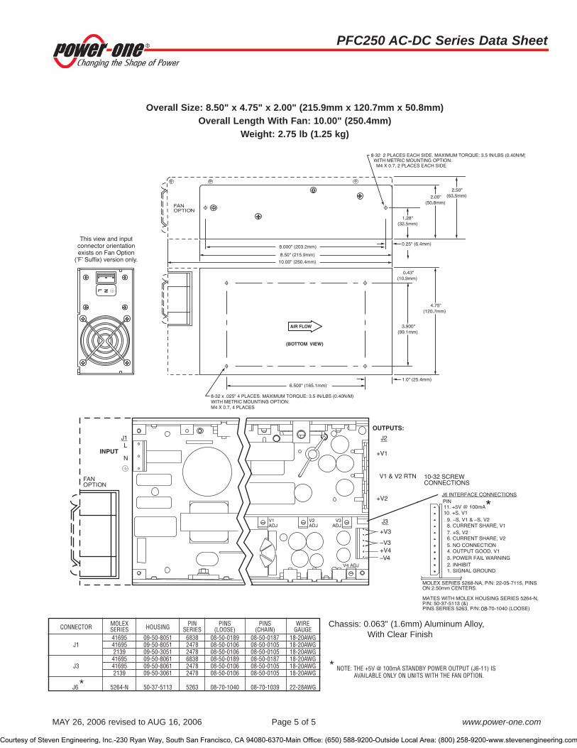
PFC250 AC-DC Series Data Sheet
MAY 26, 2006 revised to AUG 16, 2006 Page 5 of 5 www.power-one.com
Chassis: 0.063" (1.6mm) Aluminum Alloy, With Clear Finish
Overall Size: 8.50" x 4.75" x 2.00" (215.9mm x 120.7mm x 50.8mm)Overall Length With Fan: 10.00" (250.4mm)
Weight: 2.75 lb (1.25 kg)
* NOTE: THE +5V @ 100mA STANDBY POWER OUTPUT (J6-11) ISAVAILABLE ONLY ON UNITS WITH THE FAN OPTION.
08
*
CONNECTOR MOLEX HOUSING PIN PINS PINS WIRESERIES SERIES (LOOSE) (CHAIN) GAUGE41695 09-50-8051 6838 08-50-0189 08-50-0187 18-20AWG
J1 41695 09-50-8051 2478 08-50-0106 08-50-0105 18-20AWG2139 09-50-3051 2478 08-50-0106 08-50-0105 18-20AWG41695 09-50-8061 6838 08-50-0189 08-50-0187 18-20AWG
J3 41695 09-50-8061 2478 08-50-0106 08-50-0105 18-20AWG2139 09-50-3061 2478 08-50-0106 08-50-0105 18-20AWG
J6* 5264-N 50-37-5113 5263 08-70-1040 08-70-1039 22-28AWG
Courtesy of Steven Engineering, Inc.-230 Ryan Way, South San Francisco, CA 94080-6370-Main Office: (650) 588-9200-Outside Local Area: (800) 258-9200-www.stevenengineering.com

PFC375 AC-DC Series Data Sheet
MAY 26, 2006 revised to JUL 13, 2006 Page 1 of 5 www.power-one.com
Features• RoHS lead-solder-exempt compliant • Greater than 1 million hours demonstrated MTBF• Power Factor Correction (PFC) meets EN61000-3-2• Fully-regulated outputs• Main output remote sense• Current Share, Power Fail, and Power Good signals• Overtemperature, overvoltage, and overcurrent protected• Available with metric and SAE mountings• Input transient & ESD compliance to
EN61000-4-2/-3/-4/-5• Fan output voltage and optional fan
Single-Output Model SelectionMODEL OUTPUT ADJUSTMENT MAXIMUM OUTPUT LINE LOAD RIPPLE & NOISE INITIAL SETTING
VOLTAGE RANGE CURRENT (NOTE 1) REGULATION REGULATION %p-p (NOTE 2) ACCURACY
PFC375-1012 12V 10.8V to 13.5V 30A 0.2% 0.8% 1% 11.94V to 12.06VPFC375-1015 15V 12.0V to 17.0V 25A 0.2% 0.6% 1% 14.94V to 15.06VPFC375-1024 24V 21.6V to 26.4V 15A 0.5% 0.8% 1% 23.88V to 24.12VPFC375-1028 28V 25.2V to 30.8V 13.4A 0.5% 0.9% 0.9% 27.86V to 28.14VPFC375-1048 48V 46.0V to 56.0V 7.8A 0.5% 1.0% 1% 47.52V to 48.48V
The PFC375 products of the PerFormanCe Power Series incorporate high performance midrange power, active PowerFactor Correction (PFC), and high reliability to meet varied commercial and industrial requirements.Providing tightly-regulated DC power in a wide variety of single and multiple output configurations, the PFC375 isdesigned to provide full output power with only 300 Linear Feet per Minute (LFM) forced-air cooling (factory installedfan optional). Other features include remote sense, power fail, logic level inhibit, and DC power good. Main channelcurrent sharing is provided for redundant applications. The PFC375 is available with SAE mountings or optional metricmountings.The PFC375 product line is approved to the latest international regulatory standards and displays the CE Mark.
Description
NOTES: 1) Output currents ratings are expressed with 300 LFM forced air.2) Maximum peak-to-peak noise expressed as a percentage of output voltage, 20 MHz bandwidth.
Courtesy of Steven Engineering, Inc.-230 Ryan Way, South San Francisco, CA 94080-6370-Main Office: (650) 588-9200-Outside Local Area: (800) 258-9200-www.stevenengineering.com

PFC375 AC-DC Series Data Sheet
MAY 26, 2006 revised to JUL 13, 2006 Page 2 of 5 www.power-one.com
Model numbers highlighted in yellow or shaded are not recommended for new designs.
Multiple-Output Model Selection - Isolated V3 and V4 Can Be Used as Positive Or Negative Output
MODEL OUTPUT ADJUSTMENT OUTPUT PEAK OUTPUT LINE LOAD RIPPLE & NOISE INITIAL SETTINGVOLTAGE RANGE CURRENT (NOTE 1) CURRENT (NOTE 3) REGULATION REGULATION %p-p (NOTE 2) ACCURACY
+5V 4.5V to 5.5V 3.5 - 40A 40A 0.4% 0.8% 1% 4.98V to 5.02V
PFC375-4000 +12V 11.3V to 12.6V 10A 16A 0.9% 0.9% 1% 11.9V to 12.1V12V 11.3V to 12.6V 6A 6A 0.9% 0.9% 1% 11.9V to 12.1V5V Fixed 3A 3A 2% 2% 2.4% 4.9V to 5.1V+5V 4.5V to 5.5V 3.5 - 40A 40A 0.4% 0.8% 1% 4.98V to 5.02V
PFC375-4001 +12V 11.3V to 12.6V 10A 16A 0.9% 0.9% 1% 11.9V to 12.1V(Note 4) 12V 11.3V to 12.6V 6A 6A 0.9% 0.9% 1% 11.9V to 12.1V
12V 11.0V to 15.8V 3A 3A 0.9% 0.9% 1% 11.9V to 12.1V+5V 4.5V to 5.5V 3.5 - 40A 40A 0.4% 0.8% 1% 4.98V to 5.02V
PFC375-4002 +12V 11.3V to 12.6V 10A 16A 0.9% 0.9% 1% 11.9V to 12.1V(Note 5) 12V 11.3V to 12.6V 6A 6A 0.9% 0.9% 1% 11.9V to 12.1V
24V 22.0V to 28.0V 3A 3A 0.5% 0.8% 1% 23.8V to 24.2V+5V 4.5V to 5.5V 3.5 - 40A 40A 0.4% 0.8% 1% 4.98V to 5.02V
PFC375-4004 +12V 11.3V to 12.6V 10A 16A 0.9% 0.9% 1% 11.9V to 12.1V15V 14.2V to 15.8V 4A 4A 0.7% 0.7% 1% 14.9V to 15.1V15V 14.2V to 15.8V 4A 4A 0.7% 0.7% 1% 14.9V to 15.1V+5V 4.5V to 5.5V 3.5 - 40A 40A 0.4% 0.8% 1% 4.98V to 5.02V
PFC375-4005 +12V 11.3V to 12.6V 10A 16A 0.9% 0.9% 1% 11.9V to 12.1V(Note 6) 24V 22.0V to 28.0V 3A 3A 0.5% 0.8% 1% 23.8V to 24.2V
24V 22.0V to 28.0V 3A 3A 0.5% 0.8% 1% 23.8V to 24.2V+24V 21.5V to 26.4V 1 - 10A 10A 0.5% 0.8% 1% 23.8V to 24.2V
PFC375-4200 +5V 4.5V to 5.5V 10A 16A 0.4% 0.8% 1% 4.98V to 5.02V12V 11.4V to 12.6V 4A 4A 0.5% 1% 1% 11.9V to 12.1V12V 11.4V to 12.6V 4A 4A 0.5% 1% 1% 11.9V to 12.1V+24V 21.5V to 26.4V 1 - 10A 10A 0.5% 0.8% 1% 23.8V to 24.2V
PFC375-4201 +5V 4.5V to 5.5V 10A 16A 0.4% 0.8% 1% 4.98V to 5.02V15V 14.2V to 16.0V 4A 4A 0.5% 0.8% 1% 14.9V to 15.1V15V 13.7V to 16.0V 4A 4A 0.5% 0.8% 1% 14.9V to 15.1V
+5V 4.5V to 5.5V 3.5 - 50A 50A 0.4% 0.8% 1% 4.98V to 5.02V
PFC375-4500 +12V 11.3V to 12.6V 10A 16A 0.9% 0.9% 1% 11.9V to 12.1V12V 11.3V to 12.6V 6A 6A 0.9% 0.9% 1% 11.9V to 12.1V5V 4.5V to 5.5V 3A 3A 2% 0.9% 1% 4.9V to 5.1V
NOTES: 1) Output currents ratings are expressed with 300 LFM forced air.2) Maximum peak-to-peak noise expressed as a percentage of output voltage, 20 MHz bandwidth.3) Peak loads up to 450 Watts for 60 seconds or less are acceptable, (10% duty cycle max.). Peak power must not exceed 450 Watts.4) V4 can be adjusted to 16V with a minimum load of 5A on V1.5) For operation of V4 greater than 24V, consult factory.6) V3 and V4 may be series connected to obtain 48V.
Courtesy of Steven Engineering, Inc.-230 Ryan Way, South San Francisco, CA 94080-6370-Main Office: (650) 588-9200-Outside Local Area: (800) 258-9200-www.stevenengineering.com

PFC375 AC-DC Series Data Sheet
MAY 26, 2006 revised to JUL 13, 2006 Page 3 of 5 www.power-one.com
Input SpecificationsPARAMETER CONDITIONS/DESCRIPTION MIN NOM MAX UNITS
Input Voltage - AC Continuous input range. 85 264 VACInput Frequency AC Input. 47 63 HzBrown Out Protection Lowest AC input voltage that regulation is maintained with full rated loads. 85 VACHold-Up Time Over full AC input voltage range at full rated load. 20 msInput Current 85 VAC at full rated load. 6 ARMS
Input Protection Non-user serviceable internally located AC input line fuse, F10A, 250V.Inrush Surge Current Internally limited by thermistor, one cycle, 25°C. 110 VAC 35 APK
220 VAC 65Power Factor Per EN61000-3-2. 0.98 W/VAOperating Frequency Switching frequency of main transformer. 100 kHz
Output SpecificationsPARAMETER CONDITIONS/DESCRIPTION MIN NOM MAX UNITS
Efficiency Full rated load, 110 VAC. Varies with distribution of loads among outputs. 68 %Minimum Loads Single output models. 0
Multiple output models, 5V main output only. 3.5 AmpsMultiple output models, 24V main output only. 1
Ripple and Noise Full load, 20MHz bandwidth. See Model Selection ChartsOutput Power 300 LFM forced air cooling required for operation. See optional fan.
Continuous power, multiple output models. 375 WattsPeak power, all models. 450
Overshoot / Undershoot Output voltage overshoot/undershoot at turn-on. 0 VRegulation Varies by output. Total regulation includes: line changes from 85-132 VAC or See Model Selection Charts
170-264 VAC, changes in load starting at 20% load and changing to 100% load.Transient Response Recovery time, to within 1% of initial set point due to a 50-100% load change, 1 ms
3% max. deviation. (Main output only on multi-output units).Turn-On Delay Time required for initial output voltage stabilization. 1 SecTurn-On Rise Time Time required for output voltage to rise from 10% to 90%. 10 ms
Courtesy of Steven Engineering, Inc.-230 Ryan Way, South San Francisco, CA 94080-6370-Main Office: (650) 588-9200-Outside Local Area: (800) 258-9200-www.stevenengineering.com

PFC375 AC-DC Series Data Sheet
MAY 26, 2006 revised to JUL 13, 2006 Page 4 of 5 www.power-one.com
Interface Signals and Internal ProtectionPARAMETER CONDITIONS/DESCRIPTION MIN NOM MAX UNITS
Overvoltage Protection Provided on single output units and the main output only of multiple output units.PFC375-30XX, PFC375-40XX, PFC375-45XX 6.0 6.4
PFC375-1012 13.5 15.5PFC375-1015 17.0 19.5PFC375-1024 27.0 30.7 VPFC375-1028 30.8 35.0PFC375-1048 60.0 70.0PFC375-42XX 27.0 30.7
Overload Protection Fully protected against output overload and short circuit. Automatic recovery upon removal of overload condition.Overtemperature Protection System shutdown due to excessive internal temperature, automatic reset.Remote Sense Total voltage compensation for cable losses with respect to the main output. 250 mVCurrent Share Accuracy of shared current with up to 6 parallel units. 10 %Inhibit TTL compatible logic signal will inhibit outputs by the application of a logic low signal.
An open circuit or external TTL high signal allows normal operation.Input Power TTL compatible logic signal. Time before regulation dropout due to 5 msFail Warning loss of input power at 110 VAC.Power Good TTL compatible signal. Signal is low if main output is greater or less than 10% of nominal.Fan Voltage Provides 170 mA current to user-supplied fan, if fan option is not selected. 12 V
Safety, Regulatory, and EMI SpecificationsPARAMETER CONDITIONS/DESCRIPTION MIN NOM MAX UNITS
Agency Approvals UL1950.CSA 22.2 NO. 234/950. ApprovedEN60950 (TÜV).
Dielectric Withstand Voltage Input to output. 2600 VDCElectromagnetic Interference FCC CFR title 47 Part 15 Sub-Part B - Conducted. B Class
EN55022 / CISPR 22 Conducted. BESD Susceptibility Per EN61000-4-2, level 4. 8 kVRadiated Susceptibility Per EN61000-4-3, level 3. 10 V/MEFT/Burst Per EN61000-4-4, level 4. ±4 kVInput Transient Protection Per EN61000-4-5 class 3. Line to Line 1 kV
Line to Ground 2Insulation Resistance Input to output. 10 M�
Leakage Current Per EN60950, 264 VAC. 2.0 mA
Environmental SpecificationsPARAMETER CONDITIONS/DESCRIPTION MIN NOM MAX UNITS
Altitude Operating. 10k ASL Ft.Non-Operating. 40k ASL Ft.
Operating Temperature At 100% load 0 50 °CDerate linearly above 50°C by 2.5% per °C. At 50% load 0 70 °C
Storage Temperature -55 85 °CForced Air Cooling Forced air cooling of 300 LFM is required if the internal fan option is not specified.
Cooling air velocity is measured 1/4" above, at the middle of the chassis. Airflow direction is from the input section to the output section.
Temperature Coefficient 0°C to 70°C (after 15-minute warmup). ±0.02 ±0.05 %/°CRelative Humidity Non-Condensing. 5 95 %RHShock Operating: 10±3mS, 3 axis, Halfsine. 20 G
Non-operating: 10±3mS, 3 axis, Halfsine. 40Vibration Operating: 5-32 Hz 0.02 in (DA)
32-2000 Hz Sinusoidal 1 GRMS
Non-operating: 6.15 GRMS
Courtesy of Steven Engineering, Inc.-230 Ryan Way, South San Francisco, CA 94080-6370-Main Office: (650) 588-9200-Outside Local Area: (800) 258-9200-www.stevenengineering.com
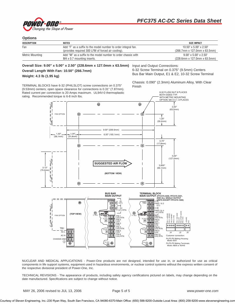
PFC375 AC-DC Series Data Sheet
MAY 26, 2006 revised to JUL 13, 2006 Page 5 of 5 www.power-one.com
OptionsDESCRIPTION NOTES SIZE IMPACT
Fan Add “F” as a suffix to the model number to order integral fan. 10.50" x 5.00" x 2.50"(provides required 300 LFM of forced air cooling). (266.7mm x 127.0mm x 63.5mm)
Metric Mounting Add “M” as a suffix to the model number to order chassis with 9.00" x 5.00" x 2.50"M4 x 0.7 mounting inserts. (228.6mm x 127.0mm x 63.5mm)
Overall Size: 9.00" x 5.00" x 2.50" (228.6mm x 127.0mm x 63.5mm)Overall Length With Fan: 10.50" (266.7mm)Weight: 4.3 lb (1.95 kg)
Input and Output Connections: 6-32 Screw Terminal on 0.375" (9.5mm) Centers Bus Bar Main Output, E1 & E2, 10-32 Screw Terminal
Chassis: 0.090" (2.3mm) Aluminum Alloy, With ClearFinishTERMINAL BLOCKS have 6-32 (PHILSLOT) screw connections on 0.375"
(9.53mm) centers; open space clearance for connections is 0.31" (7.87mm).Rated current per connection is 20 Amps maximum. UL94V-0 thermoplasticrating. Recommended torque is 6-8 inch lbs.
NUCLEAR AND MEDICAL APPLICATIONS - Power-One products are not designed, intended for use in, or authorized for use as criticalcomponents in life support systems, equipment used in hazardous environments, or nuclear control systems without the express written consent ofthe respective divisional president of Power-One, Inc.
TECHNICAL REVISIONS - The appearance of products, including safety agency certifications pictured on labels, may change depending on thedate manufactured. Specifications are subject to change without notice.
Courtesy of Steven Engineering, Inc.-230 Ryan Way, South San Francisco, CA 94080-6370-Main Office: (650) 588-9200-Outside Local Area: (800) 258-9200-www.stevenengineering.com

MCD10025 Rev. 1.1 Page 1 of 6 www.power-one.com
PLP75 AC-DC Series Data Sheet75 Watts
Description
The PLP75 is a cost-effective and efficient series of AC-DC power supplies suited for telecom, datacom, and many other applications. The PLP75 Series meets the international information technology safety standards with the CE-Mark for the European Low Voltage Directive (LVD). Active power-factor-correction (PFC) is a standard feature. PFC enables the user to comply with EN 61000-3-2 line harmonics requirements. In addition, PFC reduces line losses and rms input current to help achieve low-cost operation and makes the end product more environmentally friendly to the end users.
Single-Output Model Selection Model Nominal
Output Voltage (VDC)
Min-Max Output Current (Amps),
Convection
Min-Max Output Current (Amps),
Forced Air 1
Peak Output Current (Amps) 2
Total Regulation
(%) 3
Ripple & Noise
pk-pk % 4 PLP75-1003G 3.3 5 0.2 - 13 0.2 - 15 17.5 ±2 1
PLP75-1005G 5 5 0.2 - 13 0.2 - 15 16.5 ±2 1
PLP75-1012G 12 5 0.1 - 5.4 0.1 - 6.5 7 ±2 1
PLP75-1024G 24 5 0.1 - 2.7 0.1 - 3.1 3.5 ±2 1
PLP75-1048G 48 5 0.1 - 1.4 0.1 - 1.6 1.8 ±2 1
1 5 CFM or 150 LFM (average measurement of six equally-distributed points through a 3.5" x 1.6" (9 cm x 4 cm cross-sectional area) with power supply mounted on a 0.25" (6.35 mm) standoffs. Recommended airflow direction is from the AC side to the DC side. 2 Peak current duration for less than 30 seconds with a maximum duty cycle of 10%. 3 At 25 °C ambient including voltage set point tolerance, line and load regulation 4 Maximum peak to peak noise expressed as a percentage of output voltage, 20 MHz bandwidth. 5 Output is adjustable ±10 % of nominal.
Model numbers highlighted in yellow or shaded are not recommended for new designs.
Applications
• Telecom, datacom • Networking • Industrial • Medical instrumentation • Consumer • Gaming
Features • RoHS compliant for all six substances • 75 Watts with 5 CFM forced-air cooling • Typical 80% efficiency • 65 Watts with convection cooling • 85-264 VAC wide-range input • FCC & CISPR 22, Class "B" – Conducted EMI • Power Factor Corrected (meets IEC61000-3-2) • Typical 0.99 power factor • Height meets 1U chassis constraints • Two-year limited warranty • Safety Agency pending to UL60960-1, CSA 22.2No.
60950-1-03, and TUV EN60950/IEC 60950-1 • Compliance with EN 61000-4-2 level 4 (ESD),
EN 61000-4-3 (RF), EN 61000-4-4 level 3 (Fast Transient/Burst), EN 61000-4-5 class 3 (Surge)
Courtesy of Steven Engineering, Inc.-230 Ryan Way, South San Francisco, CA 94080-6370-Main Office: (650) 588-9200-Outside Local Area: (800) 258-9200-www.stevenengineering.com

MCD10025 Rev. 1.1 Page 2 of 6 www.power-one.com
PLP75 AC-DC Series Data Sheet75 Watts
ELECTRICAL SPECIFICATIONS
Input Specifications Parameter Conditions/Description Min. Nom. Max. Units
AC Input Voltage Range
Continuous voltage range 85 100 - 250 264 VAC
DC Input Voltage Range
Continuous voltage range; For input above 250 VDC, consult factory.
120 170 250 VDC
Frequency AC Input 47 50 - 60 63 Hz
Power Factor Complies with EN61000-3-2 Standard for Line Current Harmonics
Input current 85 VAC at 75 W 1.5 Amps rms
Inrush current 115 VAC, Max power, 25 °C 16 A pk
230 VAC, Max power, 25 °C 32 A pk
Input fuse Non-user serviceable internally located AC input line fuse is provided.
2.5 A
Efficiency At maximum output power, nominal line 80 %
Courtesy of Steven Engineering, Inc.-230 Ryan Way, South San Francisco, CA 94080-6370-Main Office: (650) 588-9200-Outside Local Area: (800) 258-9200-www.stevenengineering.com

MCD10025 Rev. 1.1 Page 3 of 6 www.power-one.com
PLP75 AC-DC Series Data Sheet75 Watts
Output Specifications Parameter Conditions/Description Min. Nom. Max. Units
Output power With convection cooling With 5 CFM forced-air cooling
1 Watts
Output DC voltages Vo1 is adjustable ±10% of nominal. 1 VDC
Output DC current 1 A
Minimum load No damage occurs to the power supply when operating at zero load.
1 A
Output ripple & noise 1 mV pk-pk
CM noise 50 mV pk-pk
Overshoot Vo1 overshoot at turn-on 3 %
Load transient Vo1 deviation due to a 50 to 100% load change at a rate of 1A/µs
±3 %
Turn-On & Turn-Off characteristics
Outputs turn ON monotonically.
Turn-on time from AC ON
Time required for output within regulation after initial application of AC input.
0.2 1.5 Sec
Turn-on Delay Tme required for output voltage to rise from 10% to 90%.
0.2 20 ms
Hold-up Time Time Vo1 is required to stay within 95% regulation after removal of AC measure from the last peak of the AC line at 115 VAC.
20 ms
Remote Sense Not available.
Control loop stability Phase margin. 45 Degrees
Gain margin. 10 dB 1 See Model Selection tables.
Fault Protection Parameter Conditions/Description Min. Nom. Max. Units
Current Limit set point Overload protected - power limit. 145 % of peak rating
Short-circuit protection Provided on all models.
OVP Trip Vo1. 115 125 135 % of set point
Courtesy of Steven Engineering, Inc.-230 Ryan Way, South San Francisco, CA 94080-6370-Main Office: (650) 588-9200-Outside Local Area: (800) 258-9200-www.stevenengineering.com

MCD10025 Rev. 1.1 Page 4 of 6 www.power-one.com
PLP75 AC-DC Series Data Sheet75 Watts
Isolation Requirements Parameter Conditions/Description Min. Nom. Max. Units
Input-to-Chassis 2121 VDC
Input-to-Output 4242 VDC
Output-to-Chassis 500 VDC
Output-to-Output 1 1 All outputs share the same common.
EMC Immunity Parameter Conditions/Description
ESD EN 61000-4-2 Level 4.
RF Susceptibility EN 61000-4-3 Level 3.
Fast Transient/Burst EN 61000-4-4 Level 3.
Surge EN 61000-4-5 Class 3.
RF Immunity EN 61000-4-6.
Magnetic Fields EN 61000-4-8.
Voltage Interruptions EN 61000-4-11.
EMC Emmisions Parameter Conditions/Description
FCC Part 15 Conducted Class B, Radiated Class A.
CISPR 22 and CISPR 11
Conducted Class B, Radiated Class A.
Environmental Specifications Parameter Conditions/Description Min. Nom. Max. Units
Cooling Rated for convection and forced-air cooling.
Audible Noise 0 dBA
Operating Temp 0 ºC to 70 ºC with linear derating to 50% above 50 ºC. Unit will start-up at -20 ºC, but will not meet all published specifications.
-20 50 70 ºC
Altitude Operating. Non-Operating.
10K 50K
ASL ft ASL ft
Storage Temp -40 85 ºC
Humidity 95% relative humidity @ 40 ºC, non-condensing
Vibration Operating: Random vibration; 5 to 500 Hz (10 minutes, each axis). Non-Operating: Random vibration; 5 to 500 Hz(10 minutes, each axis).
2.4
6
Grms
Grms
Shock Operating: half-sine, 11 ±3 ms, 3-axis. Non-Operating: half-sine, 11 ±3 ms, 3-axis.
15
40
G
G
Courtesy of Steven Engineering, Inc.-230 Ryan Way, South San Francisco, CA 94080-6370-Main Office: (650) 588-9200-Outside Local Area: (800) 258-9200-www.stevenengineering.com

MCD10025 Rev. 1.1 Page 5 of 6 www.power-one.com
PLP75 AC-DC Series Data Sheet75 Watts
Regulatory & Safety Approvals Parameter Conditions/Description Min. Nom. Max. Units
UL60950-1 Approved.
CSA-C22.2, No. 60950-1-03
Approved.
EN 60950-1 /IEC 60950-1
Approved.
CE Mark for LVD Approved.
CB Approval Approved.
Ground Leakage Current
At 230 VAC. 1.4 mA
Mechanical Specifications Parameter Conditions/Description Min. Nom. Max. Units
Dimensions Length 127 mm
Width 76.2 mm
Height, including component or component lead protrusion on the bottom of the PCB.
35 mm
Power Density With forced-air cooling. 4 W/cu in
Mounting (Location/Hardware); see Outline Drawing.
Input (Location/Connector); J1 - Molex 26-62-4030 or equivalent.
Ground connector for plastic chassis
Provided.
Output (Location/Connector); J2 - Molex 26-60-4060 or equivalent.
Outline Drawing Pins/Functions
See Mechanical Drawing.
Weight 0.36 kg
Mounting distance Note 1 0.113 in 1 The minimum distance from the bottom of the component leads (solder side) or top of the components (component side) to the customer's metal chassis should be at least 0.113 " (2.85 mm).
Courtesy of Steven Engineering, Inc.-230 Ryan Way, South San Francisco, CA 94080-6370-Main Office: (650) 588-9200-Outside Local Area: (800) 258-9200-www.stevenengineering.com

MCD10025 Rev. 1.1 Page 6 of 6 www.power-one.com
PLP75 AC-DC Series Data Sheet75 Watts
Mechanical Drawing
5.00 +/- 02
3.00+/-.02
1.37+/-.02
1.2
0.1
0.06
4.55
2.55
Ø 0.16 (4 places)
Printed Circuit Board
fastener clearance area 4 places)
safety ground connection point
J1 input connector
J2 - DC output connector(see pin-out table)
TOP VIEW
SIDE VIEW END VIEW
Pin 1 NEUTRAL
Pin 2 missing pin
Pin 3 LINE
J1 - AC CONN.
Pin #1
Pin #1
Pin 1* Vo1
Pin 2 Vo1
Pin 3 Vo1
Pin 4 DC COM
Pin 5 DC COM
Pin 6 DC COM
J2 - DC CON
safety ground connection point
NUCLEAR AND MEDICAL APPLICATIONS - Power-One products are not designed, intended for use in, or authorized for use as critical components in life support systems, equipment used in hazardous environments, or nuclear control systems without the express written consent of the respective divisional president of Power-One, Inc.
TECHNICAL REVISIONS - The appearance of products, including safety agency certifications pictured on labels, may change depending on the date manufactured. Specifications are subject to change without notice.
Courtesy of Steven Engineering, Inc.-230 Ryan Way, South San Francisco, CA 94080-6370-Main Office: (650) 588-9200-Outside Local Area: (800) 258-9200-www.stevenengineering.com

MCD10023 Rev. 1.2, 15-JUL-08 Page 1 of 7 www.power-one.com
SBLP65 AC-DC Series Preliminary Data Sheet65 Watts
Description
The SBLP65 is a compact and efficient series of AC-DC power supplies suited for telecom, datacom, and many other applications. The SBLP65 Series meets the international information technology safety standards with the CE-Mark for the European Low Voltage Directive (LVD). Its high efficiency allows a very minimal power loss in end equipment, resulting in higher reliability, ease of thermal management, and regulatory approvals for an environmentally friendly end product.
Single-Output Model Selection Model Nominal
Output Voltage (VDC)
Min-Max Output Current (Amps),
Convection
Min-Max Output Current (Amps),
Forced Air 1
Peak Output Current (Amps) 2
Total Regulation
(%) 3
Ripple & Noise mV pk-pk % 4
SBLP65-1003G 3.3 0 - 11 0 - 11 19 ±2 1.5
SBLP65-1005G 5 0 - 11 0 - 11 12 ±2 1.0
SBLP65-1012G 12 0 - 5 0 - 5.4 6.25 ±2 1.0
SBLP65-1015G 15 0 - 4 0 - 4.3 5 ±2 1.0
SBLP65-1024G 24 0 - 2.5 0 - 2.7 3.1 ±2 1.0
SBLP65-1048G 48 0 - 1.25 0 - 1.35 1.56 ±2 1.0
1 4 CFM or 105 LFM (average measurement of six equally-distributed points through a 3.5" x 1.6" (9 cm x 4 cm cross-sectional area) with power supply mounted on a 0.25" (6.35 mm) standoffs. Recommended airflow direction is from the AC input to the DC output. 2 Peak current duration for less than 30 seconds with a maximum duty cycle of 10%. During peak loading, output may exceed total regulation limits. 3 At 25 °C ambient including voltage set point tolerance, line and load regulation 4 Maximum peak-to-peak noise at 20 MHz bandwidth measured at the end of a twisted pair cable across a bypass capacitor.
Applications
• Telecom, datacom • Networking • Industrial • Medical instrumentation • Consumer • Gaming
Features • RoHS compliant for all six substances • Typical 80-85% efficiency • Quasi-resonant ZVS topology with synchronous
rectification • Compact size of 2” x 4” x 1.30” • 65 Watts with only 4-5 CFM forced-air cooling • 60 Watts with convection cooling • 90-264 VAC wide-range input • FCC & CISPR 22, Class "B" – Conducted EMI • Height meets 1U chassis constraints • Two-year limited warranty • Safety Agency pending to UL60960-1, CSA 22.2No.
60950-1-03, and TUV EN60950/IEC 60950-1 • Compliance with EN 61000-4-2 level 4 (ESD),
EN 61000-4-3 (RF), EN 61000-4-4 level 3 (Fast Transient/Burst), EN 61000-4-5 class 3 (Surge)
Courtesy of Steven Engineering, Inc.-230 Ryan Way, South San Francisco, CA 94080-6370-Main Office: (650) 588-9200-Outside Local Area: (800) 258-9200-www.stevenengineering.com

MCD10023 Rev. 1.2, 15-JUL-08 Page 2 of 7 www.power-one.com
SBLP65 AC-DC Series Preliminary Data Sheet65 Watts
Triple-Output Model Selection Model Nominal
Output Voltage (VDC)
Min-Max Output Current (Amps),
Convection
Min-Max Output Current (Amps),
Forced Air 1
Peak Output Current (Amps) 2
Total Regulation
(%) 3
Ripple & Noise
pk-pk % 4 SBLP65-3300G +3.3
+5
+12
0.4 - 6
0.2 - 2
0 - 0.3
0.4 - 7 0.2 - 3.5 0 - 0.5
10 5 1
±3
±5
±5
1.0 1.0 1.0
1 5 CFM or 220 LFM average measurement of six equally-distributed points through a 3.5" x 1.6" (9 cm x 4 cm cross-sectional area) with power supply mounted on a 0.25" (6.35 mm) standoffs. Recommended airflow direction is from the AC input to the DC output. 2 Peak current duration for less than 30 seconds with a maximum duty cycle of 10%. During peak loading, output may exceed total regulation limits. 3 At 25 °C ambient including voltage set point tolerance, line and load regulation. 4 Maximum peak-to-peak noise at 20 MHz bandwidth measured at the end of a twisted pair cable across a bypass capacitor.
ELECTRICAL SPECIFICATIONS
Input Specifications Parameter Conditions/Description Min. Nom. Max. Units
AC Input Voltage Range
Continuous voltage range 90 100 - 250 264 VAC
DC Input Voltage Range
For DC input applications, please consult factory.
VDC
Frequency AC Input 47 50 - 60 63 Hz
Power Factor Complies with EN61000-3-2 Standard for Line Current Harmonics with input power less than 75 Watts, at <60W output power
Input current At 90 VAC input and max rating 1.5 Amps rms
Inrush current 115 VAC, Max power, 25 °C 30 A pk
230 VAC, Max power, 25 °C 60 A pk
Input fuse Non-user serviceable internally located AC input line fuse is provided.
A
Efficiency At maximum power, 110 VAC Single output models above 24V output Single output 12V model Single output models below 12V and Triple output models
85 84
80
% %
%
Courtesy of Steven Engineering, Inc.-230 Ryan Way, South San Francisco, CA 94080-6370-Main Office: (650) 588-9200-Outside Local Area: (800) 258-9200-www.stevenengineering.com

MCD10023 Rev. 1.2, 15-JUL-08 Page 3 of 7 www.power-one.com
SBLP65 AC-DC Series Preliminary Data Sheet65 Watts
Output Specifications Parameter Conditions/Description Min. Nom. Max. Units
1 60 Output power With convection cooling With 5 CFM forced-air cooling for triple output models and 3 CFM forced-air cooling for single output models
1 65 Watts
Output DC voltages Single & Triple Output Models: Vo1 output is adjustable -5/+10 % of nominal
Output DC current 1 A
Minimum load Required to meet total regulation 1 A
Leakage current At 264 VAC/60 Hz 0.75 mA
Output ripple & noise 1 mV pk-pk
Overshoot Vo1 overshoot at turn-on 5 %
Load transient Vo1 deviation due to a 50 to 100% load change at a rate of 1A/µs
±5 %
Turn-On & Turn-Off characteristics
Outputs turn ON monotonically at minimum output current or at full load. Outputs turn OFF monotonically at minimum output current or at full load.
Turn-on Delay Time required for output within regulation after initial application of AC input @ 90 VAC.
3 Sec
Turn-on Rise Time Time required for output voltage to rise from 10% to 90%.
20 ms
Hold-up Time Time Vo1 is required to stay within 95% regulation after removal of AC measure from the last peak of the AC line at 120 VAC and max power.
16 ms
Remote Sense Maximum compensation.2 500 mV
Control loop stability Phase margin. 45 Degrees
Gain margin. 10 dB 1 See Model Selection tables. 2 Remote sense available on single-output models only.
Fault Protection Parameter Conditions/Description Min. Nom. Max. Units
Current Limit Protection
Protection is provided.
Short-circuit Protection Provided with auto-recovery. ADC
OVP Trip Vo1, 3.3 V Vo1, 5 V Vo1, 12 V Vo1, 24 V Vo1, 48 V
3.6 5.6 14 29 55
3.75 6.2
15.35 31.6 57.5
3.95 6.9
16.7 34.2 60
VDC
Courtesy of Steven Engineering, Inc.-230 Ryan Way, South San Francisco, CA 94080-6370-Main Office: (650) 588-9200-Outside Local Area: (800) 258-9200-www.stevenengineering.com
MCD10023 Rev. 1.2, 15-JUL-08 Page 4 of 7 www.power-one.com
SBLP65 AC-DC Series Preliminary Data Sheet65 Watts
Isolation Requirements Parameter Conditions/Description Min. Nom. Max. Units
Input-to-Chassis 2121 VDC
Input-to-Output 4242 VDC
Output-to-Chassis 500 VDC
Output-to-Output For triple output models 1 1 All outputs share the same common.
EMC Immunity Parameter Conditions/Description
ESD EN 61000-4-2 Level 2.
RF Susceptibility EN 61000-4-3 Level 3.
Fast Transient/Burst EN 61000-4-4 Level 3.
Surge EN 61000-4-5 Class 3.
RF Immunity EN 61000-4-6. Class 3.
Magnetic Fields EN 61000-4-8.
Voltage Interruptions EN 61000-4-11.
EMC Emmisions Parameter Conditions/Description
FCC Part 15 Conducted Class B, Radiated Class A.
CISPR 22 and CISPR 11
Conducted Class B, Radiated Class A.
Environmental Specifications Parameter Conditions/Description Min. Nom. Max. Units
Cooling Rated for convection and forced-air cooling.
Audible Noise 0 dBA
Operating Temp -10 ºC to 50 ºC with linear derating to 50% at 70 ºC. Unit will start up at -10 ºC, but will not meet all published specifications.
-10 50 70 ºC
Altitude Operating. Non-Operating.
10K 50K
ASL ft ASL ft
Storage Temp -40 85 ºC
Humidity 95% relative humidity @ 40 ºC, non-condensing
Vibration Operating: Random vibration; 5 to 500 Hz (10 minutes, each axis). Non-Operating: Random vibration; 5 to 500 Hz(10 minutes, each axis).
2.4
6
Grms
Grms
Shock Operating: half-sine, 11 ±3 ms, 3-axis. Non-Operating: half-sine, 11 ±3 ms, 3-axis.
15
40
G
G
Courtesy of Steven Engineering, Inc.-230 Ryan Way, South San Francisco, CA 94080-6370-Main Office: (650) 588-9200-Outside Local Area: (800) 258-9200-www.stevenengineering.com

MCD10023 Rev. 1.2, 15-JUL-08 Page 5 of 7 www.power-one.com
SBLP65 AC-DC Series Preliminary Data Sheet65 Watts
Regulatory & Safety Approvals Parameter Conditions/Description Min. Nom. Max. Units
UL60950-1 3.3V and 5V single-output models are pending.
CSA-C22.2, No. 60950-1-03
3.3V and 5V single-output models are pending.
EN 60950-1 /IEC 60950-1
3.3V and 5V single-output models are pending.
CE Mark for LVD 3.3V and 5V single-output models are pending.
CB Approval 3.3V and 5V single-output models are pending.
Ground Continuity At 12 VAC. 40 A
Mechanical Specifications Parameter Conditions/Description Min. Nom. Max. Units
Dimensions Length 101.6 mm
Width 50.8 mm
Height, including component or component lead protrusion on the bottom of the PCB.
33.02 mm
Power Density With forced-air cooling. 4.81 W/cu in
Mounting (Location/Hardware); see Outline Drawing.
Input (Location/Connector); J1 - Molex 41791 series or equivalent
Output (Location/Connector); J2 - Molex 41791 series or equivalent
Remote Sense Combined into J2, pins 5 & 6 for single-output models. Not available for triple-output models.
Outline Drawing Pins/Functions
See Mechanical Drawing.
Weight 0.115 Kg
Connector kit Consult factory
Mounting distance Distance from the bottom of the components or component leads (solder side) or top of the components (component side) to the customer's metal chassis
2.87 mm
Reliability Parameter Conditions/Description Min. Nom. Max. Units
Calculated MTBF 250,000 Hours
Demonstrated MTBF 550,000 Hours
Courtesy of Steven Engineering, Inc.-230 Ryan Way, South San Francisco, CA 94080-6370-Main Office: (650) 588-9200-Outside Local Area: (800) 258-9200-www.stevenengineering.com

MCD10023 Rev. 1.2, 15-JUL-08 Page 6 of 7 www.power-one.com
SBLP65 AC-DC Series Preliminary Data Sheet65 Watts
Mechanical Drawing SBLP65 Single-Output Drawing:
4.00 +/- 04
2.00 +/-.04
1.30+/-.04
1.10
0.14
0.06
3.75
1.75
Ø 0.16 (4 places)
Printed Circuit Board
fastener clearance area 0.25 DIA (4 places)
J1 input connector
J2 - DC output connector(see pin-out table)
Pin 1 VoutPin 2 VoutPin 3 COMMONPin 4 COMMONPin 5 -SensePin 6 +Sense
TOP VIEW
SIDE VIEW END VIEW
J2 - DC CONN.
Pin 1 AC LinePin 3 AC Neutral
J1 - AC CONN.
Pin #1
Pin #1
PCB AC Ground Connection Point - Solder side
safety ground connection point
0.1
Courtesy of Steven Engineering, Inc.-230 Ryan Way, South San Francisco, CA 94080-6370-Main Office: (650) 588-9200-Outside Local Area: (800) 258-9200-www.stevenengineering.com

MCD10023 Rev. 1.2, 15-JUL-08 Page 7 of 7 www.power-one.com
SBLP65 AC-DC Series Preliminary Data Sheet65 Watts
Mechanical Drawing SBLP65 Triple-Output Drawing: NUCLEAR AND MEDICAL APPLICATIONS - Power-One products are not designed, intended for use in, or authorized for use as critical components in life support systems, equipment used in hazardous environments, or nuclear control systems without the express written consent of the respective divisional president of Power-One, Inc.
TECHNICAL REVISIONS - The appearance of products, including safety agency certifications pictured on labels, may change depending on the date manufactured. Specifications are subject to change without notice.
4.00 +/- 04
2.00 +/-.04
1.30+/-.04
1.10
0.14
0.06
3.75
1.75
Ø 0.16 (4 places)
Printed Circuit Board
fastener clearance area 0.25 DIA (4 places)
J1 input connector
J2 - DC output connector(see pin-out table)
Pin 1 V1Pin 2 V1Pin 3 COMMONPin 4 COMMONPin 5 V3Pin 6 V2
TOP VIEW
SIDE VIEW END VIEW
J2 - DC CONN.
Pin 1 AC Line Pin 3 AC Neutral
J1 - AC CONN.
Pin #1
Pin #1
PCB AC Ground Connection Point - Solder side
safety ground connection point
Courtesy of Steven Engineering, Inc.-230 Ryan Way, South San Francisco, CA 94080-6370-Main Office: (650) 588-9200-Outside Local Area: (800) 258-9200-www.stevenengineering.com

SPL Series
The SPL Series has been discontinued.
Please review our chassis-mount products page at: http://www.power-one.com/chassis-mount/
for replacement power solutions.
For schematics and repair information, a technical support contact form is available at: http://www.power-one.com/cgi-bin/start.cgi/dynamic/selector/emailtech.html
Courtesy of Steven Engineering, Inc.-230 Ryan Way, South San Francisco, CA 94080-6370-Main Office: (650) 588-9200-Outside Local Area: (800) 258-9200-www.stevenengineering.com

SWA Series
The SWA Series has been discontinued. Please review our ac-dc products page at: http://www.power-one.com/cgi-bin/acdc_summaries.cgi?prodtype=chm&sort=watts
for replacement power solutions.
For schematics and repair information, a technical support contact form is available at: http://www.power-one.com/cgi-bin/start.cgi/dynamic/selector/emailtech.html
Courtesy of Steven Engineering, Inc.-230 Ryan Way, South San Francisco, CA 94080-6370-Main Office: (650) 588-9200-Outside Local Area: (800) 258-9200-www.stevenengineering.com

UPS Products
Power-One does not manufacture stand-alone AC-to-AC uninterruptible power sources but can provide UPS solutions as a component in a complete Network Power System.
• Visit http://www.power-one.com/products/telecom_power.html for information describing our Network Power Systems products with battery-back-up capabilities.
• Please contact our technical support department to discuss a Network Power Systems
solution: http://www.power-one.com/cgi-bin/start.cgi/dynamic/selector/emailtech.html
Courtesy of Steven Engineering, Inc.-230 Ryan Way, South San Francisco, CA 94080-6370-Main Office: (650) 588-9200-Outside Local Area: (800) 258-9200-www.stevenengineering.com