blue star chiller air & water cooled screw chiller r22 dx manual
DESCRIPTION
Chiller manualTRANSCRIPT

USER’SMANUAL
Air Cooled and Water Cooled Screw Chillers
High on reliabilityLow on operating costs

2
SCREW CHILLER (Air & Water Cooled)
Revised January 2008
No part of this publication may be reproduced in anymanner whatsoever without permission in writing from theExecutive Vice President, Airconditioning Projects Division,Blue Star Limited.
While due care has been taken to avoid errors or misinterpretation,Blue Star Limited is neither liable nor responsible for consequenceof any action taken, on the basis of this publication.
Since ASHRAE standards use the FPS system, FPS nomenclatureis used in some places in this publication for convenient reference.
Published by Blue Star Limited, Airconditioning Projects Division.
For restricted circulation only. Not for sale.

3
USER'S MANUAL
Contents
Introduction ...................................................................................................................... 4
Features ........................................................................................................................... 5
Nomenclature.................................................................................................................... 8
Technical Specifications .................................................................................................... 9
Rigging and Installation .................................................................................................... 27
Carel Controller ............................................................................................................... 30
Screw Compressor ......................................................................................................... 47
Pre start up, Testing, Commissioning and Operation ....................................................... 54
Trouble Shooting ............................................................................................................. 84
Maintenance .................................................................................................................... 87
Spares Part List .............................................................................................................. 90
Field Feed Back Form ....................................................................................................114
Commissioning and Handing over report ........................................................................116
Water Quality .................................................................................................................117
Log Report .....................................................................................................................118
Warranty Claim Form .....................................................................................................119
Warranty ....................................................................................................................... 120
Blue Star Service Offices .............................................................................................. 121
4
SCREW CHILLER (Air & Water Cooled)
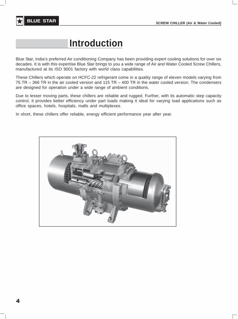
Blue Star, India’s preferred Air conditioning Company has been providing expert cooling solutions for over sixdecades. It is with this expertise Blue Star brings to you a wide range of Air and Water Cooled Screw Chillers,manufactured at its ISO 9001 factory with world class capabilities.
These Chillers which operate on HCFC-22 refrigerant come in a quality range of eleven models varying from75 TR – 366 TR in the air cooled version and 115 TR – 400 TR in the water cooled version. The condensersare designed for operation under a wide range of ambient conditions.
Due to lesser moving parts, these chillers are reliable and rugged. Further, with its automatic step capacitycontrol, it provides better efficiency under part loads making it ideal for varying load applications such asoffice spaces, hotels, hospitals, malls and multiplexes.
In short, these chillers offer reliable, energy efficient performance year after year.
Introduction

5
USER'S MANUAL
Features
CompressorThe BSC Series semi hermetic screw compressors incorporated in the chillers follow state-of-the-artmanufacturing processes which are ISO 9001 certified and use high precision machinery.
The salient features of these compressors are:
• Highly efficient with low noise levels
• Tested in accordance with ARI Standards
• Due to few moving parts such as Male and Female Screws and Slider valve, these compressors haveminimal wear and tear
• Each compressor has the latest 5 to 6 Patented Profile design, with separate Radial and Axial forceBearings, Built-in Oil Separator, PTC Motor winding protection, Discharge temperature protection withits controller, Oil level switch and Oil differential pressure switch. This guarantees reliability and longlife of bearings under heavy working operating conditions.
• Each Compressor has Step capacity control from 25% to 100%, making it suitable for part loadapplications and efficient under part load conditions. The capacity control also helps in limiting thestarting current.
Liquid InjectionThe refrigerant suction gas cools the winding of the Semi hermetic Screw Compressor Motor. During partload operation where the suction gas circulation is less, as an abundant precaution, liquid refrigerant is injectedto the suction side of the compressor to cool the motor winding. Liquid injection during this period keeps themotor winding temperature within limits. This is provided as a standard feature to enhance the life of thecompressor.
EvaporatorThe shell and tube evaporator has inner grooved copper tubes for better heat transfer. The tubes are designedto optimize for refrigerant and water velocities.

6
SCREW CHILLER (Air & Water Cooled)
Control CentreThe control centre is mounted in the framework of the chiller. It isprovided with an advanced microprocessor control panel which hasunique features and advantages.
• The cooler outlet temperature can be controlled accuratelywithin a close tolerance of + 0.5°F
• In-built time delays for compressor single phase / phasereversal protection and anti freeze protection
• Password protection at two levels.
Optional features in Control Centre
• RS 485 port & TCP/ IP web gate for remote connectivity,fault indication and status facility
• PC connectivity and remote monitoring without BMSthrough dedicated telephone line, Gateway and Modem.
Following additional features are available in Air Cooled version:
EconomiserRefrigerant liquid to liquid plate type heat exchanger is provided for the economiser system. Theliquid refrigerant is sub cooled to enhance the capacity thereby reducing power consumption (IKW/TR) and enhancing the Coefficient of Performance (COP).
Oil CoolerEffective lubrication of bearing depends on the viscosity of lubricant, which in turn depends onthe oil temperature. To ensure effective lubrication for longevity, oil cooler is provided as a standardoption for Aircooled Application.
• BMS compatibility with JC N2, BACnet and Modbus protocol with Translator.
• Windows based support system to provide complete status on all operations both locally and remotely.History, static and dynamic graphing to aid in commissioning, trouble shooting and evaluation.
These features help in accurate operation and protection of the chiller.

7
USER'S MANUAL
Air cooled condenserThe air cooled condenser coils uses copper tubes and aluminum fins. The inner groovedtype copper tubes used in the condenser provide increased surface area for better heattransfer.
FansThe propeller type fan profiles are with 5 lobes, bird wing design which optimizes both thenoise level and the power consumption against required air flow and static pressure.
SpringsSpecially designed springs are supplied along with the units to minimize the transmission of vibration.
Optional items available in air cooled version are:
• Hydrophobic coated aluminium fins
• Coil protection guards

8
SCREW CHILLER (Air & Water Cooled)
Nomenclature
Nomenclature - Air Cooled Chiller
LIQUID NOMINAL CAPACITY
NO. OF COMPRESSORSCHILLER
AIR COOLED SCREW COMPRESSOR
L C A X 1 - 075 D i A
DIRECT EXPANSION
Nomenclature - Water Cooled Chiller
REFRIGERANT R22
REVISION
LIQUID NOMINAL CAPACITY
NO. OF COMPRESSORSCHILLER
SCREW COMPRESSOR
L C W X 1 - 115 D i B
DIRECT EXPANSION
REFRIGERANT R22
REVISION
WATER COOLED

9
USER'S MANUAL
Technical Specifications
Technical Specification for Air Cooled Screw Chiller (Single Compressor)
Description Unit LCAX1-075 D i A LCAX1-102 D i A LCAX 1-145 D i A LCAX1-206 D i A
Nominal Cooling Capacity KW (TR) 263.7 (75) 359.3 (102) 509.82(145) 724.29 (206)
Compressor Semihermetic Screw
Model BSC-075A BSC-105A BSC-145A BSC-210A
Quantity No. 1 1 1 1
Motor type Semi-hermetic Refrigerant Cooled, 3Ph., 2 Pole Squirrel Cage, Induction Motor
Operating Speed RPM 2950 2950 2950 2950
Power Supply 400 V(+/- 10%) , 3 Ph. , 50Hz
Ccompressor Rated Current. Amp. 131.9 182.6 250.9 357
Compressor Locked Rotor Current Amp. 730 735 1100 1760
Compressor Starting Current Amp. 230 245 370 590
Class of Insulation F F F F
Compressor Power Consumption kW 81.1 112.3 154.7 219.8
Unit starting Current Amps 235 252.5 380 605
Unit Maximum Full Load Current Amp. 180 251 345 490
Unit Power Consumption kW 85.9 119.5 164.3 234.2
R-22 Refrigerant Charge Kg 67 90 130 175
Oil Charge (Blue Star ACS) Litres/compr 16 16 23 28
Condenser
Total Face Area Sq. Mt.(Sq Ft) 10.28 (110) 14.9 (160) 19.8 (213) 29.7(320)
Rows Deep No. 3 3 3 3
Tube Material 3/8" Inner grooved,.Copper
(D) OD x Thickness mm x mm 9.5 x 0.304 9.5 x 0.304 9.5 x 0.304 9.5 x 0.304
Type of Aluminium Fins Super Slit
Fins per Inch 14 14 14 14
Fan for Air Cooled Condenser
Fan Dia mm 915 915 915 915
Quantity No. 4 6 8 12
Air Flow CFM 48,000 72,000 96000 1,44,000
Condenser Fan Motor
Type Totally enclosed, Pad Mounted
Quantity No. 4 6 8 12
Speed RPM 700 700 700 700
Full Load Current Amp. 2.6 2.6 2.6 2.6
Power Input KW 1.2 1.2 1.2 1.2

10
SCREW CHILLER (Air & Water Cooled)
Rating Conditions
1. Entering Air over Condenser Temperature: 95oF
2. Entering Cooler Water Temperature: 54oF, Leaving Cooler Water Temperature: 44oF
3. Cooler Fouling Factor : 0.0001 Hr. Sq.ft.Deg. F/BTU
Technical Specification for Air Cooled Screw Chiller (Single Compressor)
Description Unit LCAX1-075 D i A LCAX1-102 D i A LCAX 1-145 D i A LCAX1-206 D i A
DX-Cooler
Model YCH-92A YCH-103A YCH-152A YCH-222A
Shell ID mm 311.2 371 419.1 488
Shell Thickness mm 6 8 8 8
Tube Type and Material Inner Grooved Tubes with External Plain
No. of Tubes Nos 196 252 310 508
Tube OD and Thickness IN 5/8" OD * 0.031 5/8" OD * 0.031 5/8" OD * 0.031 5/8" OD * 0.031
Tube Length FT 7 7 8 8
Surface Area Inside Sq. FT 347.39 446.64 627.93 1029
Surface Area Outside Sq. FT. 224.37 290.09 407.75 668.00
No of Pass (water side) Nos 1 1 1 1
No of Pass (Refrigerant side) Nos 4 4 4 4
No of Refrigerant Circuit NOS 1 1 1 1
Water Connection Size In/Out INCH 6" NB 6" NB 6" NB 8" NB
Water Flow Rate
Min.. USGPM 150 204 290 412
Max.. USGPM 225 306 435 618
Expansion Valve Thermostatic
Economiser Brazed Plate Heat Exchanger
Overall Dimension
Length mm 2700 3800 4820 7260
Wideth mm 2040 2040 2040 2040
Height mm 2486 2495 2495 2495
Net Weight (approx) Kg. 2600 3300 4180 6050
Operating Weight (approx) Kg. 2677 3382 4358 6250

11
USER'S MANUAL
Technical Specification for Air Cooled Screw Chiller (Twin Compressors)
Description Units LCAX2-150 D i A LCAX2-177 D i A LCAX2-204 D i A LCAX 2-247 D i A
Nominal Cooling Capacity KW (TR) 527.4 (150) 622.3(177) 717.2 (204) 868.4(247)
Compressor Semihermetic Screw
Model BSC-075A BSC-075A + BSC-105A BSC-105A BSC-105A + BSC-145A
Quantity No. 2 2 2 2
Motor type Semi-hermetic Refrigerant Cooled, 3Ph., 2 Pole Squirrel Cage, Induction Motor
Operating Speed RPM 2950 2950 2950 2950
Power Supply 400 V(+/- 10%) , 3 Ph., 50Hz
Ccompressor Rated Current. Amp. 263.8 (131.9 X 2) 314.5 (131.9 + 182.6) 365.2 (182.6 X 2) 433.5 (182.6 + 250.9)
Compressor Locked Rotor Current Amp. 685, 685 685, 735 735, 735 735, 1100
Compressor Starting Current Amp. 230, 230 230, 245 245, 245 245, 370
Class of Insulation F F F F
Compressor Power Consumption kW 162.2 192.3 224.6 267.3
Unit starting Current Amps 377 397 450 578
Unit Maximum Full Load Current Amp. 360 430 502 596
Unit Power Consumption kW 171.8 204.3 239 284.1
R-22 Refrigerant Charge Kg 135 159 184 222
Oil Charge (Blue Star ACS) Litres/compr 16 + 16 16 + 16 16 + 16 18+23
Condenser
Total Face Area Sq. Mt.(Sq Ft) 19.8 (213) 9.84 (106) + 19.8 (213) 29.7(320) 34.6(373)
Rows Deep No. 3 3/2 3 3
Tube Material 3/8" Inner grooved,.Copper
(D) OD x Thickness mm x mm 9.5 x 0.304 9.5 x 0.304 9.5 x 0.304 9.5 x 0.304
Type of Aluminium Fins Super Slit
Fins per Inch 14 14 14 14
Fan for Air Cooled Condenser
Fan Dia mm 915 915 915 915
Quantity No. 8 12 12 14
Air Flow CFM 96,000 144,000 144,000 168,000
Condenser Fan Moror
Type Totally enclosed, Pad Mounted
Quantity No. 8 12 12 14
Speed RPM 700 700 700 700
Full Load Current Amp. 2.6 2.6 2.6 2.6
Power Input KW 1.2 1.2 1.2 1.2

12
SCREW CHILLER (Air & Water Cooled)
Technical Specification for Air Cooled Screw Chiller (Twin Compressors)
Rating Conditions
1. Entering Air over Condenser Temperature: 95oF
2. Entering Cooler Water Temperature: 54oF, Leaving Cooler Water Temperature: 44oF
3. Cooler Fouling Factor : 0.0001 Hr. Sq.ft.Deg. F/BTU
Description Units LCAX2-150 D i A LCAX2-177 D i A LCAX2-204 D i A LCAX 2-247 D i A
DX-Cooler
Model YCH-177 A YCH-202A YCH-222 A YCH103A+YCH-152A
Shell ID mm 419.1 445 488 371 + 419.1
Shell Thickness mm 8 8 8 8
Tube Type and Material Inner Grooved Tubes with External Plain
No. of Tubes Nos 378 412 508 252+310
Tube OD and Thickness IN 5/8" OD * 0.031 5/8" OD * 0.031 5/8" OD * 0.031 5/8" OD * 0.031
Tube Length FT 8 8 8 7'+8'
Surface Area Inside Sq. FT 765.67 834.54 1029 446+627
Surface Area Outside Sq. FT. 497.19 541.91 668.00 290+407
No of Pass (water side) Nos 1 1 1 1
No of Pass (Refrigerant side) Nos 4 4 4 4
No of Refrigerant Circuit NOS 2 2 2 2
Water Connection Size In/Out INCH 8" NB 8" NB 8" NB 6'’NB+6'’NB
Water Flow Rate
Min.. USGPM 300 354 408 494
Max.. USGPM 450 531 612 741
Expansion Valve Thermostatic
Economiser Brazed Plate Heat Exchanger
Overall Dimension
Length mm 4820 7260 7260 8630
Wideth mm 2040 2040 2040 2040
Height mm 2495 2495 2495 2495
Net Weight (approx) Kg. 4700 5300 6300 7350
Operating Weight (approx) Kg. 4873 5485 6500 7618

13
USER'S MANUAL
Technical Specification for Air Cooled Screw Chiller (Twin Compressors)
Description Units LCAX2-290 D i A LCAX2-320 D i A LCAX2-366 D i A
Nominal Cooling Capacity KW (TR) 1019.6(290) 1125.1(320) 1286.8.1(366)
Compressor Semihermetic Screw
Model BSC-145A + BSC-145A BSC-160A BSC-160A +BSC-210A
Quantity No. 2 2 2
Motor type Semi-hermetic Refrigerant Cooled, 3Ph., 2 Pole Squirrel Cage, Induction Motor
Operating Speed RPM 2950 2950 2950
Power Supply 400V(+/- 10%), 3Ph., 50Hz 400V(+/- 10%), 3Ph., 50Hz 400V(+/- 10%), 3Ph., 50Hz
Ccompressor Rated Current. Amp. 502 (250.9 + 250.9) 552 (276 X 2) 633 (276 + 357)
Compressor Locked Rotor Current Amp. 1100, 1100 1480, 1480 1480, 1760
Compressor Starting Current Amp. 370, 370 495, 495 495, 590
Class of Insulation F F F
Compressor Power Consumption kW 309.4 336.6 389.4
Unit starting Current Amps 651 808 903
Unit Maximum Full Load Current Amp. 690 766 867
Unit Power Consumption kW 328.6 360.6 415.8
R-22 Refrigerant Charge Kg 265 288 329.4
Oil Charge (Blue Star ACS) Litres/compr 23+23 23+23 23+28
Condenser
Total Face Area Sq. Mt.(Sq Ft) 39.6(426) 39.6(426) 49.53(533)
Rows Deep No. 3 4 3
Tube Material 3/8" Inner grooved,.Copper
(D) OD x Thickness mm x mm 9.5 x 0.304 9.5 x 0.304 9.5 x 0.304
Type of Aluminium Fins Super Slit
Fins per Inch 14 14 16
Fan for Air Cooled Condenser
Fan Dia mm 915 915 915
Quantity No. 16 16 20
Air Flow CFM 192,000 232,000 260,000
Condenser Fan Moror
Type Totally enclosed, Pad Mounted
Quantity No. 16 16 20
Speed RPM 700 860 700/860
Full Load Current Amp. 2.6 3.5 3.5
Power Input KW 1.2 1.5 1.2/1.5
DX-Cooler
Model YCH-152A+YCH152A YCH-177 A+ YCH177A YCH-177A+YCH222A
Shell ID mm 419.1+419.1 419.1+419.1 419.1+488

14
SCREW CHILLER (Air & Water Cooled)
Technical Specification for Air Cooled Screw Chiller (Twin Compressors)
Rating Conditions
1. Entering Air over Condenser Temperature: 95oF
2. Entering Cooler Water Temperature: 54oF, Leaving Cooler Water Temperature: 44oF
3. Cooler Fouling Factor : 0.0001 Hr. Sq.ft.Deg. F/BTU
Description Units LCAX2-290 D i A LCAX2-320 D i A LCAX2-366 D i A
Shell Thickness mm 8 8 8
Tube Type and Material Inner Grooved Tubes with External Plain
No. of Tubes Nos 310+310 378 +378 378+508
Tube OD and Thickness IN 5/8" OD * 0.031 5/8" OD * 0.031 5/8" OD * 0.031
Tube Length FT 8+8 8+8 8 + 8
Surface Area Inside Sq. FT 627+627 765.67+765.67 765.67 + 1029
Surface Area Outside Sq. FT. 407+407 497.19+497.19 497.2 + 668
No of Pass (water side) Nos 1 1 1
No of Pass (Refrigerant side) Nos 4 4 4
No of Refrigerant Circuit NOS 2 2 2
Water Connection Size In/Out INCH 6'’NB+6'’NB 8" NB+8'’NB 8" NB + 8'’NB
Water Flow Rate
Min.. USGPM 580 640 732
Max.. USGPM 870 960 1098
Expansion Valve Thermostatic
Economiser Brazed Plate Heat Exchanger
Overall Dimension
Length mm 9650 9650 12090
Width mm 2040 2040 2040
Height mm 2495 2495 2495
Net Weight (approx) Kg. 8034 9135 9753
Operating Weight (approx) Kg. 8390 9430 10126
15
USER'S MANUAL
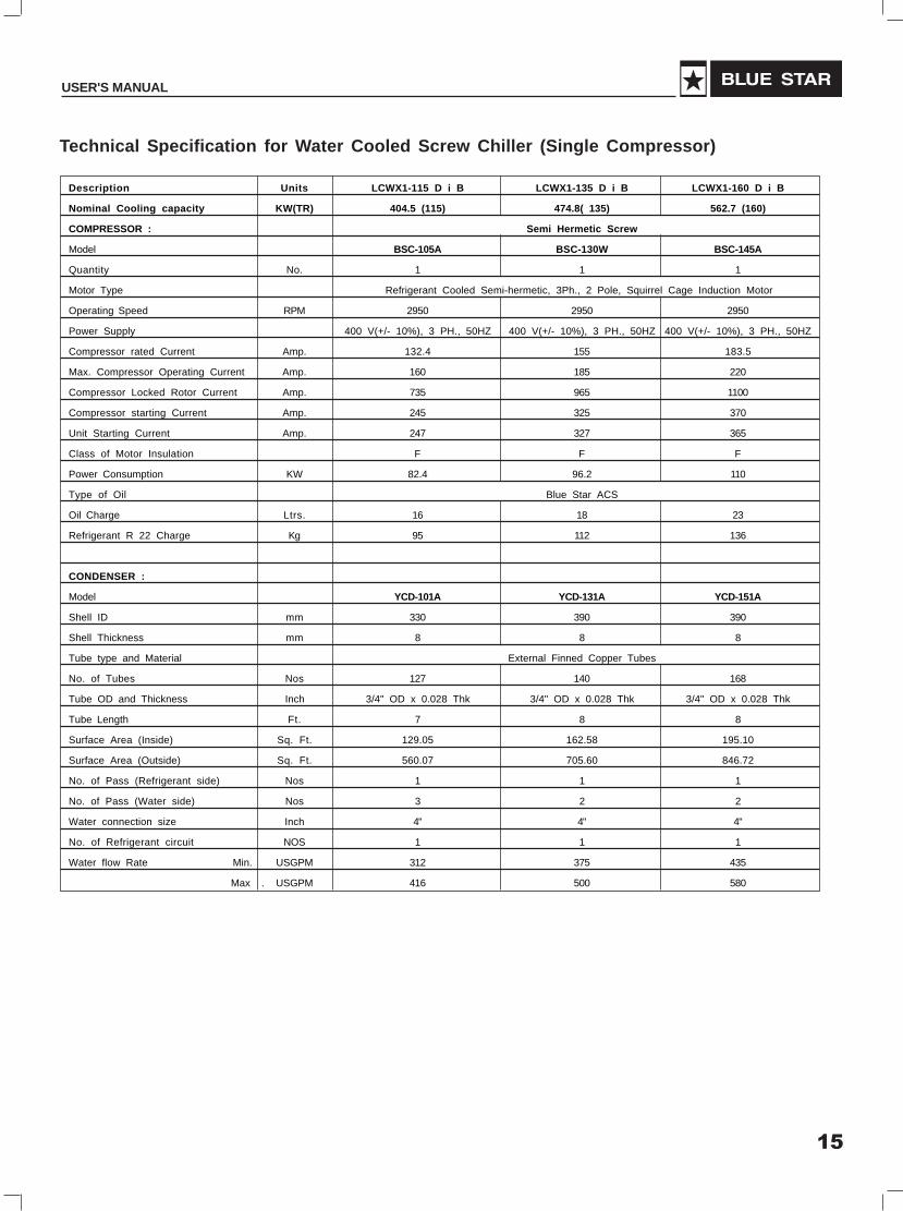
Technical Specification for Water Cooled Screw Chiller (Single Compressor)
Description Units LCWX1-115 D i B LCWX1-135 D i B LCWX1-160 D i B
Nominal Cooling capacity KW(TR) 404.5 (115) 474.8( 135) 562.7 (160)
COMPRESSOR : Semi Hermetic Screw
Model BSC-105A BSC-130W BSC-145A
Quantity No. 1 1 1
Motor Type Refrigerant Cooled Semi-hermetic, 3Ph., 2 Pole, Squirrel Cage Induction Motor
Operating Speed RPM 2950 2950 2950
Power Supply 400 V(+/- 10%), 3 PH., 50HZ 400 V(+/- 10%), 3 PH., 50HZ 400 V(+/- 10%), 3 PH., 50HZ
Compressor rated Current Amp. 132.4 155 183.5
Max. Compressor Operating Current Amp. 160 185 220
Compressor Locked Rotor Current Amp. 735 965 1100
Compressor starting Current Amp. 245 325 370
Unit Starting Current Amp. 247 327 365
Class of Motor Insulation F F F
Power Consumption KW 82.4 96.2 110
Type of Oil Blue Star ACS
Oil Charge Ltrs. 16 18 23
Refrigerant R 22 Charge Kg 95 112 136
CONDENSER :
Model YCD-101A YCD-131A YCD-151A
Shell ID mm 330 390 390
Shell Thickness mm 8 8 8
Tube type and Material External Finned Copper Tubes
No. of Tubes Nos 127 140 168
Tube OD and Thickness Inch 3/4" OD x 0.028 Thk 3/4" OD x 0.028 Thk 3/4" OD x 0.028 Thk
Tube Length Ft. 7 8 8
Surface Area (Inside) Sq. Ft. 129.05 162.58 195.10
Surface Area (Outside) Sq. Ft. 560.07 705.60 846.72
No. of Pass (Refrigerant side) Nos 1 1 1
No. of Pass (Water side) Nos 3 2 2
Water connection size Inch 4" 4" 4"
No. of Refrigerant circuit NOS 1 1 1
Water flow Rate Min. USGPM 312 375 435
Max . USGPM 416 500 580

16
SCREW CHILLER (Air & Water Cooled)
Technical Specification for Water Cooled Screw Chiller (Single Compressor)
Rating Conditions
1. Entering Cooler Water temp 54oF, Leaving Cooler Water temp. 44oF
2. Cooler Fouling Factor 0.0001 Hr.Ft2.F/Btu
3. Entering Condenser Water temperature 85oF, Leaving Coondenser Water temperature 95oF
4. Condenser Fouling Factor 0.00025 Hr.Ft2.F/Btu
Description Units LCWX1-115 D i B LCWX1-135 D i B LCWX1-160 D i B
DX-COOLER
Model YCH-103A YCH-122A YCH-152A
Shell ID mm 371 371 416
Shell Thickness mm 8 8 8
Tube type and Material Inner Groove Copper Tubes
No. of Tubes Nos 252 252 310
Tube OD and Thickness Inch 5/8" OD * 0.031 5/8" OD * 0.031 5/8" OD * 0.031
Tube Length Ft. 7 8 8
Surface area (Inside) Sq. Ft. 446.64 510.45 627.93
Surface Area (Outside) Sq. Ft. 290.09 323.17 407.75
No. of Pass (Water side) Nos 1 1 1
No. of Pass (Refrigerant side) Nos 4 4 4
Water Connection Size Inch 6" NB 6" NB 6" NB
No. of Refrogerant Circuits Nos 1 1 1
Water Flow Rate Min. USGPM 208 250 290
Max. USGPM 312 375 435
EXPANSION VALVE Thermostatic
Make Sporlan
Model VVE-100 VVE-100 OVE-70-2#
OVERALL DIMENSIONS :
Length mm 2700 2953 2979
Width mm 800 900 900
Height mm 2000 2102 2102
Net Weight Approx Kg. 2500 2700 3365
Operating Weight Kg. 2725 3025 3750

17
USER'S MANUAL
Technical Specification for Water Cooled Screw Chiller (Single Compressor)
Description Units LCWX1-175 D i B LCWX1-225 D i B
Nominal Cooling capacity KW(TR) 615.5 (175) 791.3 (225)
COMPRESSOR : Semi Hermetic Screw
Model BSC-160A BSC-210A
Quantity No. 1 1
Motor Type Refrigerant Cooled Semi- hermetic, 3 Ph., 2 Pole, Squirrel Cage Induction Motor
Operating Speed RPM 2950 2950
Power Supply 400 V(+/- 10%), 3PH., 50HZ 400 V(+/- 10%), 3PH., 50HZ
Compressor rated Current Amp. 200.7 258.6
Max. Compressor Operating Current Amp. 240 310
Compressor Locked Rotor Current Amp. 1480 1760
Compressor starting Current Amp. 495 590
Unit Starting Current Amp. 489 580
Class of Motor Insulation F F
Power Consumption KW 120.7 156.1
Type of Oil Blue Star ACS
Oil Charge Ltrs. 23 28
Refrigerant R 22 Charge Kg 150 195
CONDENSER :
Model YCD-176A YCD-221A
Shell ID mm 390 457
Shell Thickness mm 8 8
Tube type and Material External Finned Copper Tubes
No. of Tubes Nos 199 248
Tube OD and Thickness Inch 3/4" OD x 0.028 Thk 3/4" OD x 0.028 Thk
Tube Length Ft . 8 8
Surface Area (Inside) Sq. Ft. 231.10 288.00
Surface Area (Outside) Sq. Ft. 1002.96 1249.92
No. of Pass (Refrigerant side) Nos 1 1
No. of Pass (Water side) Nos 2 2
Water connection size Inch 5" 6"
No. of Refrigerant circuit NOS 1 1
Water flow Rate Min. USGPM 480 630
Max. USGPM 640 840

18
SCREW CHILLER (Air & Water Cooled)
Technical Specification for Water Cooled Screw Chiller (Single Compressor)
Rating Conditions
1. Entering Cooler Water temp 54oF, Leaving Cooler Water temp. 44oF
2. Cooler Fouling Factor 0.0001 Hr.Ft2.F/Btu
3. Entering Condenser Water temperature 85oF, Leaving Coondenser Water temperature 95oF
4. Condenser Fouling Factor 0.00025 Hr.Ft2.F/Btu
Description Units LCWX1-175 D i B LCWX1-225 D i B
DX-COOLER
Model YCH-177 A YCH-222 A
Shell ID mm 416 416
Shell Thickness mm 8 8
Tube type and Material Inner Groove Copper Tubes
No. of Tubes Nos 378 508
Tube OD and Thickness Inch 5/8" OD * 0.031 5/8" OD * 0.031
Tube Length Ft . 8 8
Surface area (Inside) Sq. Ft. 765.67 1029
Surface Area (Outside) Sq. Ft. 497.19 668.00
No. of Pass (Water side) Nos 1 1
No. of Pass (Refrigerant side) Nos 4 4
Water Connection Size Inch 8" NB 8" NB
No. of Refrogerant Circuits Nos 1 1
Water Flow Rate Min. USGPM 320 420
Max. USGPM 480 630
EXPANSION VALVE Thermostatic
Make Sporlan
Model OVE-70-2# VVE-100-2#
OVERALL DIMENSIONS :
Length mm 2987 3087
Width mm 900 900
Height mm 2102 2269
Net Weight Approx Kg. 3650 4600
Operating Weight Kg. 4000 5040

19
USER'S MANUAL
Technical Specification for Water Cooled Screw Chiller (Twin Compressors)
Description Units LCWX2-225 D i B LCWX2-270 D i B LCWX2-315 D i B
Nominal Cooling capacity KW(TR) 791.3 ( 225) 949.6 (270) 1107.9 (315)
COMPRESSOR : Semi Hermetic Screw
Model BSC-150A BSC-110A + BSC-145A BSC-145A
Quantity No. 2 2 2
Motor Type Refrigerant Cooled Semi- hermetic, 3 Ph., 2 Pole, Squirrel Cage Induction Motor
Operating Speed RPM 2950 2950 2950
Power Supply 400 V(+/- 10%), 3PH., 50HZ 400 V(+/- 10%), 3PH., 50HZ 400 V(+/- 10%), 3PH., 50HZ
Compressor rated Current Amp. 264.8 315.9 367
Max. Compressor Operating Current Amp. 320 (160 x 2) 380 (160+220) 440
Compressor Locked Rotor Current Amp. 735, 735 735, 1100 1100, 1100
Compressor starting Current Amp. 245, 245 245, 370 370, 370
Unit Starting Current Amp. 385 481.5 550
Class of Motor Insulation F F F
Power Consumption KW 164.9 192.5 220
Type of Oil Blue Star ACS
Oil Charge Ltrs. 16 + 16 16 + 23 23 + 23
Refrigerant R 22 Charge Kg 180 231 275
CONDENSER :
Model YCD-222 A YCD101A+YCD151A YCD-151A+YCD151A
Shell ID mm 457 330+390 390+390
Shell Thickness mm 8 8 8
Tube type and Material External Finned Copper Tubes
No. of Tubes Nos 248 127+168 168+168
Tube OD and Thickness Inch 3/4" OD x 0.028 Thk 3/4" OD x 0.028 Thk 3/4" OD x 0.028 Thk
Tube Length Ft . 8 8 8
Surface Area (Inside) Sq. Ft. 288.00 324.15 390.19
Surface Area (Outside) Sq. Ft. 1249.92 1406.79 1693.44
No. of Pass (Refrigerant side) Nos 1 1 1
No. of Pass (Water side) Nos 2 2 2
Water connection size Inch 6" 4"+4" 4"+4"
No. of Refrigerant circuit NOS 2 2 2
Water flow Rate Min. USGPM 624 750 870
Max. USGPM 832 1000 1160

20
SCREW CHILLER (Air & Water Cooled)
Rating Conditions
1. Entering Cooler Water temp 54oF, Leaving Cooler Water temp. 44oF
2. Cooler Fouling Factor 0.0001 Hr.Ft2.F/Btu
3. Entering Condenser Water temperature 85oF, Leaving Coondenser Water temperature 95oF
4. Condenser Fouling Factor 0.00025 Hr.Ft2.F/Btu
Technical Specification for Water Cooled Screw Chiller (Twin Compressors)
Description Units LCWX2-225 D i B LCWX2-270 D i B LCWX2-315 D i B
DX-COOLER
Model YCH-222 A YCH-103A+YCH152A YCH-152A+YCH152A
Shell ID mm 488 371+416 416+416
Shell Thickness mm 8 8 8
Tube type and Material Inner Groove Copper Tubes
No. of Tubes Nos 508 252+310 310+310
Tube OD and Thickness Inch 5/8" OD * 0.031 5/8" OD * 0.031 5/8" OD * 0.031
Tube Length Ft . 8 8+8 8+8
Surface area (Inside) Sq. Ft. 1029 1074.57 627+627
Surface Area (Outside) Sq. Ft. 651.46 697.84 407+407
No. of Pass (Water side) Nos 1 1 1
No. of Pass (Refrigerant side) Nos 4 4 4
Water Connection Size Inch 8" NB 6"NB+6"NB 6'’NB+6'’NB
No. of Refrogerant Circuits Nos 2 2 2
Water Flow Rate Min. USGPM 416 500 580
Max.. USGPM 624 750 870
EXPANSION VALVE Thermostatic
Make Sporlon
Model VVE-100-2# V V E-100-1# + OVE-70-2# OVE-70-2# + OVE-70-2#
OVERALL DIMENSIONS :
Length mm 3100 3400 3400
Width mm 1220 1800 1800
Height mm 2300 2300 2300
Net Weight approx Kg. 5000 5400 6526
Operating Weight Kg. 5450 6050 7280

21
USER'S MANUAL
Technical Specification for Water Cooled Screw Chiller (Twin Compressors)
Description Units LCWX2-345 D i B LCWX2-400 D i B
Nominal Cooling capacity KW(TR) 1213.4 (345) 1406.8 (400)
COMPRESSOR : Semi Hermetic Screw
Model BSC-160A BSC-160A+BSC-210A
Quantity No. 2 2
Motor Type Refrigerant Cooled Semi-hermetic, 3 Ph., 2 Pole, Squirrel Cage Induction Motor
Operating Speed RPM 2950 2950
Power Supply 400 V(+/- 10%), 3PH., 50HZ 400 V(+/- 10%), 3PH., 50HZ
Compressor rated Current Amp. 401.4 459.3
Max. Compressor Operating Current Amp. 480 (240 x 2) 550 (240 + 310)
Compressor Locked Rotor Current Amp. 1480, 1480 1480, 1760
Compressor starting Current Amp. 495, 495 495, 590
Unit Starting Current Amp. 692 769
Class of Motor Insulation F F
Power Consumption KW 241.4 276.7
Type of Oil Blue Star ACS
Oil Charge Ltrs. 23 + 23 23 + 28
Refrigerant R 22 Charge Kg 304 351
CONDENSER :
Model YCD-176A+YCD176 A YCD176A+YCD222A
Shell ID mm 390+390 390+457
Shell Thickness mm 8 8
Tube type and Material External Finned Copper Tubes
No. of Tubes Nos 199+199 199+248
Tube OD and Thickness Inch 3/4" OD x 0.028 Thk 3/4" OD x 0.028 Thk
Tube Length Ft . 8 8
Surface Area (Inside) Sq. Ft. 462.19 519.10
Surface Area (Outside) Sq. Ft. 2005.92 2252.88
No. of Pass (Refrigerant side) Nos 1 1
No. of Pass (Water side) Nos 2 2
Water connection size Inch 5"+5" 5"+6"
No. of Refrigerant circuit NOS 2 2
Water flow Rate Min. USGPM 960 1110
Max. USGPM 1280 1480

22
SCREW CHILLER (Air & Water Cooled)
Rating Conditions
1. Entering Cooler Water temp 54oF, Leaving Cooler Water temp. 44oF
2. Cooler Fouling Factor 0.0001 Hr.Ft2.F/Btu
3. Entering Condenser Water temperature 85oF, Leaving Coondenser Water temperature 95oF
4. Condenser Fouling Factor 0.00025 Hr.Ft2.F/Btu
Technical Specification for Water Cooled Screw Chiller (Twin Compressors)
Description Units LCWX2-345 D i B LCWX2-400 D i B
DX-COOLER
Model YCH-177A+YCH177A YCH-177A+YCH222A
Shell ID mm 416+416 416+488
Shell Thickness mm 8 8
Tube type and Material Inner Groove Copper Tubes
No. of Tubes Nos 378 +378 378+508
Tube OD and Thickness Inch 5/8" OD * 0.031 5/8" OD * 0.031
Tube Length Ft . 8+8 8 + 8
Surface area (Inside) Sq. Ft. 765.67+765.67 765.67 + 1029
Surface Area (Outside) Sq. Ft. 497.19+497.19 497.2 + 668
No. of Pass (Water side) Nos 1 1
No. of Pass (Refrigerant side) Nos 4 4
Water Connection Size Inch 8" NB+8'’NB 8" NB + 8'’NB
No. of Refrogerant Circuits Nos 2 2
Water Flow Rate Min. USGPM 640 740
Max.. USGPM 960 1110
EXPANSION VALVE Thermostatic
Make Sporlon
Model OVE-70-2# + OVE-70-2# OVE-70-2# + VVE-100-2#
OVERALL DIMENSIONS :
Length mm 3400 3400
Width mm 1800 1800
Height mm 2450 3000
Net Weight approx Kg. 6862 7541
Operating Weight Kg. 7500 8300

23
USER'S MANUAL
YCH-52A YCH-62A YCH-77A YCH-92A
20 1.5
40 2.5 1.4
60 3.5 2.5 1.75
80 5 4 3
100 7 6 4.5
120 10 8.3 6.5
140 13 11 9 5.5
160 16.5 14 11.5 6.5
180 21 17.5 14.5 8
200 26 21 18 10
220 25 21 12
240 29 24.5 14
260 28.3 16
280 32.5 18.5
300 21
320 24
340 26
360 28
380
400
YCH-103A YCH-122A YCH-132A YCH-177A YCH-202A YCH-222AYCH-152A
100
150 6 3.5 2
200 10 7.5 5.5 4.5 2.8 0.5
250 15 10.3 8.3 6.5 4.6 2.5
300 21 14 11 8.5 6.5 4
350 27 19 14 12 9.2 5.8
400 25 18 15 12 7.5
450 36 22 19 15 9.3
500 26 23 19 11.5
550 32 28 24 14
600 40 33 28 17
650 32 20
700 24
Pressure Drop

24
SCREW CHILLER (Air & Water Cooled)

25
USER'S MANUAL
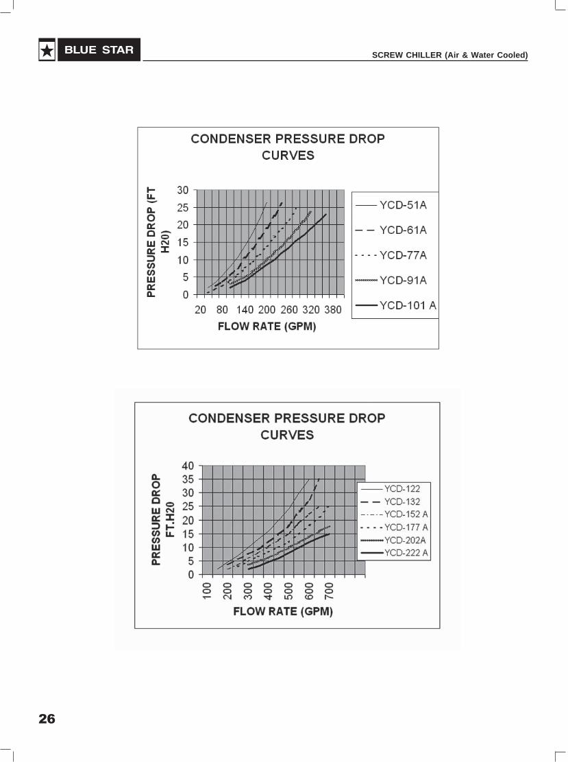
YCD-122 YCD-132 YCD-152 A YCD-177 A YCD-202 A YCD-222 A
100
150 2
200 4.6 3.6 2
250 7 5.5 3.5 2.8
300 10 7.5 6 4.7 3.5 2
350 13 9.2 8 6.5 5 3
400 16 12 10.2 8.2 6.1 4.5
450 20 15 12.5 10 8 6
500 24 18 15 12 10 8
550 30 23 19 15 12 10
600 35 27.5 22 18 14 12
650 35 25 21 16 13.5
700 25 18 15
YCD-51A YCD-61A YCD-77A YCD-91A YCD-101 A
2 0.5
60 3.5 2.5 1.5
80 5.5 3.6 2.5
100 8 5.5 4 3 2
120 10.5 7.5 5.5 4 3
140 14 10.5 7.5 5 4
160 17.5 13 9.5 6.5 5.5
180 21.5 16 11.5 8 7
200 26.5 19 14 10 8.5
220 22.5 16.5 12 10
240 26 19 14 12
260 21.5 16 13.5
280 24.5 18.5 15.5
300 21 17
320 23.5 19
340 21
360 23
26
SCREW CHILLER (Air & Water Cooled)

27
USER'S MANUAL
RiggingWhen the chiller arrives at Warehouse/Site, proper rigging and handling is mandatory during unloading andleading the unit into position.
Care must be taken to keep the unit upright during rigging. Avoid unnecessary jerking or rough handling.
Proper hoisting straps should be used when rigging (nylon flat rope). It is also mandatory that an experiencedand reliable rigger be selected to handling unloading and final placement of the equipment. The rigger mustbe advised that the unit contains internal components that require to be kept in an upright position. Caremust be exercised to avoid twisting of the equipment.
Rigging and Installation
StorageCheck for transportation damages if any and take up with factory for any damages.
In case the site is not ready to install the chiller, proper care should be taken to store the chiller in a coveredspace. Check up the pressure of the unit when received. If the pressure is not retained in the system, thesystem should be pressure tested immediately, repair the leakages if any and charge the system withNitrogen. Never keep the system without pressure.
Installation (Aircooled)Proper care should be taken to make the foundation for the Chiller. Study the GA drawings of respectivemodels and arrange for wider foundation as rquired to accommodate all the springs within the width offoundation since the springs centres ar enot in one straight line. In case the Chiller is located on the rooftop, ensure that the same is located in such a way that the load of the same is transferred to the columnsand not to the slab directly. The foundation should be properly levelled.

28
SCREW CHILLER (Air & Water Cooled)
Install the Chiller on the springs specifically designed and supplied along with the unit.
The unit should not be located nearer to any heat source or any high tension line running above. (Especiallynear the Control Panel end)
Adequate space around the Chiller as recommended in the GA Drawing should be made available formaintenance purpose.
The chilled water and condenser water piping connections to the cooler and condenser should be terminatedpreferably with flexible connections to avoid transmission of vibration if any. The piping shall be supportedexternal to the unit as per the recommended practice. Alternately 2 nos. of National Couplings in series canbe provided for the cooler connection.
Use recommended size of power cable to be terminated to the Control Panel of the unit. Use 3½ coreAluminium cable along with double earthing and terminate through proper lugs. Avoid any sharp bend for thecable at the termination point. The cable shall be adequately supported. Two separate incomer cables arerequired for the chillers with twin compressors.

29
USER'S MANUAL
Installation (Watercooled)
Proper care should be taken to make the foundation for the Chiller. In case the Chiller is located on the rooftop, ensure that the same is located in such a way that the load of the same is transferred to the columnsand not to the slab directly. The foundation should be properly levelled.
Install the Chiller on the Foundation/Pedestal and grout by using foundation bolts. The Chiller should be levelledon the foundation. The unit should not be located nearer to any heat source or any high tension line runningabove.
Adequate space around the Chiller as recommended in the GA Drawing should be made available formaintenance purpose.
The chilled water and condenser water piping connections to the cooler and condenser should be terminatedpreferably with flexible connections to avoid transmission of vibration if any. The piping shall be supportedexternal to the unit as per the recommended practice. Alternately use 2nos. of national couplings in series.
Use recommended size of power cable to be terminated to the Switch Fuse unit of the Panel of the unit.Use 3½ core Aluminium cable along with double earthing and terminate through proper lugs. Avoid any sharpbend for the cable at the termination point. The cable shall be adequately supported. Two separate incomercables are required for the chillers with twin compressors.

30
SCREW CHILLER (Air & Water Cooled)
1.General Characteristics pCO1 Medium (18 Din modules)
• 12 optically-isolated digital inputs, 24Vac 50/60 Hz or 24Vdc;
• Optically-isolated digital inputs, 24Vac/Vdc or 230Vac (50/60Hz);
• Digital relay outputs (3 of which with changeover contact and 4 optional SSR);
• 4 analog inputs, configurable as NTC, 0/1V, 0/5V, 0/20mA, 4/20mA.
• 2 analog inputs, configurable as NTC and ON-OFF
• 2 NTC analogue inputs
• 2 x 0/10Vdc analogue outputs.
• 2 PWM outputs for phase-cutting speed controllers.
Carel ControllerFor Screw Chiller with Step Capacity Control
31
USER'S MANUAL
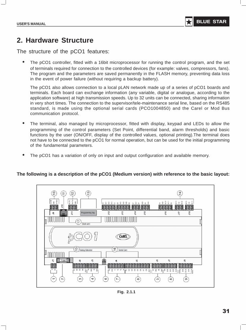
2. Hardware Structure
The structure of the pCO1 features:
• The pCO1 controller, fitted with a 16bit microprocessor for running the control program, and the setof terminals required for connection to the controlled devices (for example: valves, compressors, fans).The program and the parameters are saved permanently in the FLASH memory, preventing data lossin the event of power failure (without requiring a backup battery).
The pCO1 also allows connection to a local pLAN network made up of a series of pCO1 boards andterminals. Each board can exchange information (any variable, digital or analogue, according to theapplication software) at high transmission speeds. Up to 32 units can be connected, sharing informationin very short times. The connection to the supervisor/tele-maintenance serial line, based on the RS485standard, is made using the optional serial cards (PCO1004850) and the Carel or Mod Buscommunication protocol.
• The terminal, also managed by microprocessor, fitted with display, keypad and LEDs to allow theprogramming of the control parameters (Set Point, differential band, alarm thresholds) and basicfunctions by the user (ON/OFF, display of the controlled values, optional printing).The terminal doesnot have to be connected to the pCO1 for normal operation, but can be used for the initial programmingof the fundamental parameters.
• The pCO1 has a variation of only on input and output configuration and available memory.
The following is a description of the pCO1 (Medium version) with reference to the basic layout:
Fig. 2.1.1

32
SCREW CHILLER (Air & Water Cooled)
1. Power supply connector [G (+), G0 (-)]
2. 250Vac, 2A fuse, slow-blow (T2 A)
3. Universal analogue inputs, NTC, 0/1V, 0/5 V, 0/20mA, 4/20mA
4. Passive analogue inputs, NTC and ON/OFF
5. Passive analogue inputs, NTC
6. Yellow power LED and 3 signal LEDs
7. 0/10V analogue outputs and PWM phase-cutting outputs
8. Digital inputs, 24Vac/Vdc
9. Digital inputs, 230Vac or 24Vac/Vdc
10. Connector with Vref for power to 5V ratiometric probes, and Vterm for power to ARIAterminal
11. Connector for all the standard pCO* series terminals and for downloading the applicationsoftware
12. PLAN local network connector
13. Connector for the programming key
14. Digital relay outputs
15. Door for selecting the type of analogue inputs
16. Door for inserting the serial card:
- RS485 for supervisor
- RS232 for modem interface
- Gateway (protocol converter)
17. Door for inserting the clock card

33
USER'S MANUAL
InstallationPower supply
The pCO1 can be powered at: 22/38Vdc and 24Vac ±15%, 50 z, with a maximum power input Pmax= 13W.For alternating current power supplies, during installation use a Class II safety transformer, rated to at least40VA and with a 24Vac output. To supply more than one pCO1 controller with the same transformer, its ratedpower must be n x 40VA, where n is the number of controllers supplied by the transformer, independently ofthe version of the controller. The power supply to the pCO1 controller/controllers and the terminal/terminalsmust be separated from the power supply to the other electrical devices (power contactors and otherelectromechanical components), inside the electrical panel. If the transformer secondary is earthed, makesure that the ground wire is connected to terminal G0.When powering a series of pCO1 boards connectedin a pLAN network, make sure that the G and G0 connections are correct (G0 must be same for all theboards). The table below summaries the possible status of the power LED.
LED Status DescriptionYellow On Power Supply Present
Off Power Supply absentTable 4.2.1
Fig. 4.2.1

34
SCREW CHILLER (Air & Water Cooled)
The following warnings must be respected for correct connection:
• Power supply different from that specified can seriously damage the system;
• Use cable plugs suitable for the terminals being used. Loosen each screw and insert the cable plug,and then tighten the screws. At the end of the operation lightly tug the cables to check that they aretight;
• Separate as much as possible the probe signal and digital input cables from the inductive load andpower cables, to avoid possible electromagnetic disturbance. Never use the same channeling(including that used for the electrical cables) for the power cables and probe cables. Avoid the probecables being installed in the immediate vicinity of power devices (contactors, circuit breakers or thelike);
• Reduce the length of the sensor cables where possible and avoid spiraling around power devices.The probe connection must be made using shielded cables (minimum cross section for each lead:0.5 mm2);
• Avoid touching or nearly-touching the electronic components on the boards, to avoid (extremelydangerous) electrostatic discharges from the user to the components;
• If the power supply transformer secondary is earthed, check that the ground wire corresponds to thelead connected to terminal G0 in the controller;
• Separate the power supply to the digital outputs from the power supply to the pCO1;
• Do not fasten the cables to the terminals by pressing the screwdriver with excessive force, to avoiddamaging the pCO1.
Connecting the analog inputs
The analog inputs can be configured for the more common sensors on the market: NTC, 0/1V, 0/10V, 0/20mA, 4/20mA. The different types of sensors can be selected using the correspondingdipswitches, as in the following figure.
Fig. 4.4.1

35
USER'S MANUAL
Fig. 4.4.2
Warning: for the power supply to the active probes, the 24Vdc available at the +VDC terminal can be used;the maximum current is 100mA, thermally protected against short-circuits.
36
SCREW CHILLER (Air & Water Cooled)
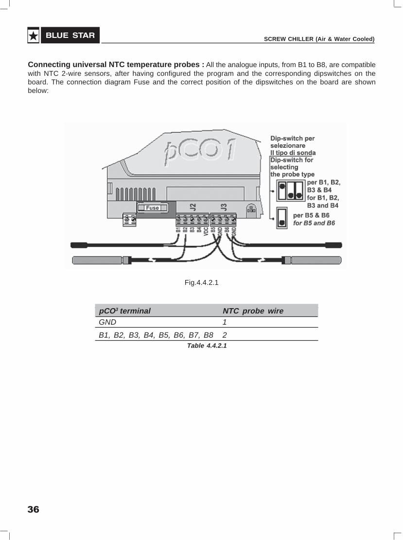
Connecting universal NTC temperature probes : All the analogue inputs, from B1 to B8, are compatiblewith NTC 2-wire sensors, after having configured the program and the corresponding dipswitches on theboard. The connection diagram Fuse and the correct position of the dipswitches on the board are shownbelow:
pCO3 terminal NTC probe wireGND 1
B1, B2, B3, B4, B5, B6, B7, B8 2Table 4.4.2.1
Fig.4.4.2.1
37
USER'S MANUAL
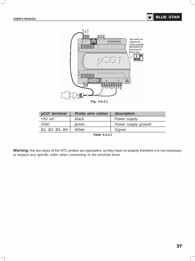
Warning: the two wires of the NTC probes are equivalent, as they have no polarity therefore it is not necessaryto respect any specific order when connecting to the terminal block.
pCO1 terminal Probe wire colour description+5V ref black Power supplyGND green Power supply groundB1, B2, B3, B4 White Signal
Table 4.4.4.1
Fig. 4.4.4.1
38
SCREW CHILLER (Air & Water Cooled)
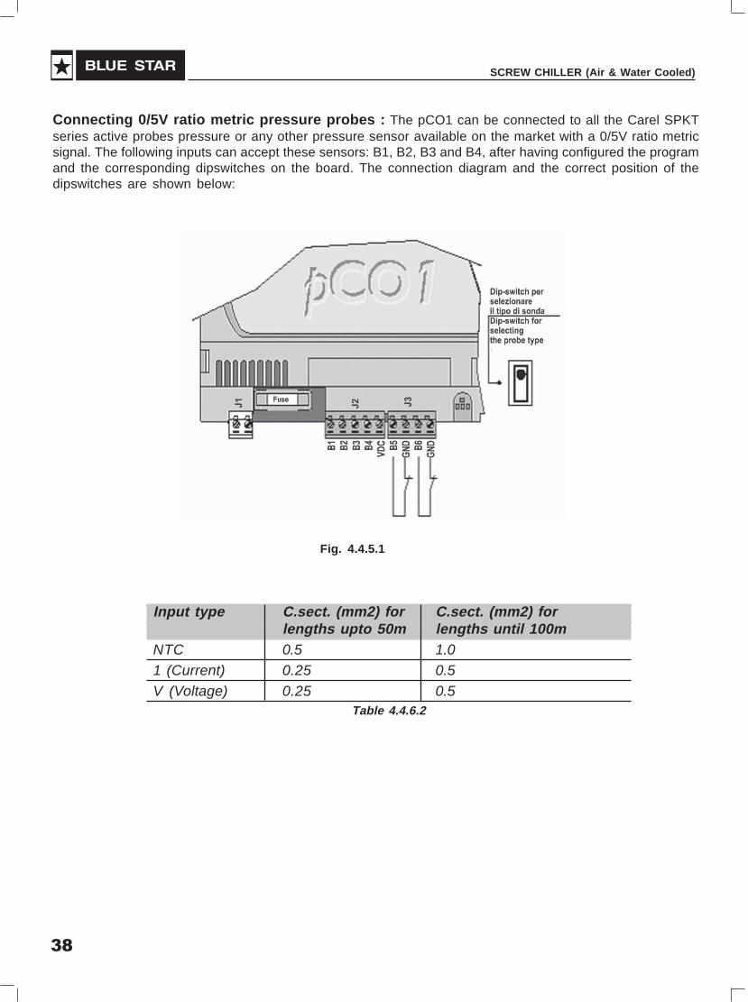
Connecting 0/5V ratio metric pressure probes : The pCO1 can be connected to all the Carel SPKTseries active probes pressure or any other pressure sensor available on the market with a 0/5V ratio metricsignal. The following inputs can accept these sensors: B1, B2, B3 and B4, after having configured the programand the corresponding dipswitches on the board. The connection diagram and the correct position of thedipswitches are shown below:
Input type C.sect. (mm2) for C.sect. (mm2) forlengths upto 50m lengths until 100m
NTC 0.5 1.01 (Current) 0.25 0.5V (Voltage) 0.25 0.5
Table 4.4.6.2
Fig. 4.4.5.1

39
USER'S MANUAL
Connecting the digital inputs :
The pCO1 features up to 14 digital inputs for connecting safety devices, alarms, device status, and remoteswitches. These inputs can work at 24Vac, 24Vdc and some at 230Vac.
WARNING: separate the probe signal and digital input cables as much as possible from the inductive loadand power cables, to avoid possible electromagnetic disturbance
24Vac digital inputs :
The following figure represents one of the more common connection diagrams for the 24Vac digital inputs.
Connecting the digital outputs :
The pCO1 features up to 13 digital outputs with electromechanical relays.
For ease of installation, the common terminals of some of the relays have been grouped together. If the diagramin Fig. 4.8.1.1 is used, the current at the common terminals must not exceed the rating (nominal current) ofa single terminal.
The relays are divided into groups, according to the degree of insulation. Inside each group, the relays havejust single insulation and thus must have the same voltage (generally 24Vac or 110/230Vac). Between thegroups there is double insulation and thus the groups can have different voltages.
Electromechanical relay outputs :
Installing the user terminal :
The connection between the user terminal and the pCO1 is made using a 6-way telephone cable suppliedby Carel.To make the connection, simply insert the telephone connector in terminal J10 on the pCO1 and interminal B on the user terminal. Insert the connector fully into in the terminal until it clicks into place. To removethe connector, simply press lightly on the plastic flap and remove the cable.
The pCO1 can also work without the terminal; do not disconnect and then reconnect the terminal to the pCO1without first having waited around 5 seconds (if the operation is performed with the unit on).
For devices used in residential environments or similar, and thus subject to CEI EN 55014-1 -04/98, anystandard terminals connected by J10 must use a shielded cable. The shield must be connected to the GNDterminal of J11.
Fig. 4.8.1.1

40
SCREW CHILLER (Air & Water Cooled)
The electrical connections are the following. Connect the telephone cable (code S90CONN00* from the powerboard (code PCO1*) into the corresponding jack. For model PCOI00PGL0 only, connect the 24Vac (30VA)power supply to the screw terminal block. If the same transformer is used for the pCO1, G and G0 must bethe same on the pCO1 and the terminal.
pAN network :
As already mentioned, the pCO1 controllers can be connected to the pLAN local network, allowing thecommunication of data and information from one location (node) to another. Each pCO1 can be connectedto a Carel supervisory network, using the optional PCO1004850 cards.
The pCO1 terminals can monitor the control variables (temperature, humidity, pressure, I/O, alarms) fromone or more boards. If one or more terminals are disconnected or malfunctioning, the control programcontinues to function correctly on each pCO1 board. Generally, the application program can monitor the statusof the network and intervene as a consequence to ensure the continuity of the control functions.
Figure 5.1, shows the pLAN network connection diagram: a maximum of 32 units can be connected (includingI/O interface cards and user interface cards).The 32nd unit can only be a terminal. All the versions of thepCO1 can be connected in a local pLAN network without requiring additional boards (Fig. 5.1).
The programs for the different applications (e.g.: standard chiller, standard air-conditioner, compressor packs,...) can not be automatically integrated into a local network: they must be modified to consider the networkstrategy and structure, and then be recompiled using the Easy Tools system.
All the devices connected to the pLAN network are identified by their own individual address, from 1 to 32 forthe terminals and from 1 to 31 for the I/O boards. As the terminals and the pCO1 I/O boards use the sametype of address, terminals and pCO1 boards cannot have the same identifier.
The addresses are set for the terminals using the dipswitches on the rear. The network can be made up ofany type of terminal, LED, 4x20 LCD and graphic, as well as pCO and pCO1 controllers.

41
USER'S MANUAL
Setting the pCO1 address :
The pCO1 controller does not have dipswitches for setting the pLAN network address.The pLAN address isset using a standard 4x20 LCD terminal. Proceed as follows:
• Disconnect the pCO1 from the power supply;
• Organise a standard Carel 4x20 LCD terminal with the address set to 0;
• Connect the terminal to the pCO1;
• Disconnect the pCO1 from any plan connections to other controllers (terminal J11);
• Power the pCO1, pressing the UP and ALARM buttons at the same time;
• After a few seconds the following screen will be displayed:
• To modify the address simply use the UP and DOWN buttons, and then press ENTER to confirm.
Setting the terminal address :
The address can be set in the range from 1/32 using the dipswitches 1/6 on the rear.
The graphic terminal does not require the setting of the address, as this is determined by the program EPROM.
Fig. 5.2.1 shows the rear view of the terminal board.
Important Warning: if the application software does not envisage a pLAN local network, the dipswitchesmust be positioned to 0.
Fig. 5.2.1
42
SCREW CHILLER (Air & Water Cooled)
5.4 pLAN Electrical Connections
Connection between boards in a pLAN network is carried out using an AWG20/22 shielded cable, twistedpair plus shield. The boards are connected in parallel, with terminal J11 as the reference.
Pay ATTENTION to the network polarity: RX/TX+ on one board must be connected to RX/TX+ on the otherboards; the same is true for RX/TX-.
Fig. 5.4.1 shows a diagram of a number of boards connected in a pLAN network and powered by the sametransformer, typical for a number of boards connected inside the same electrical panel.
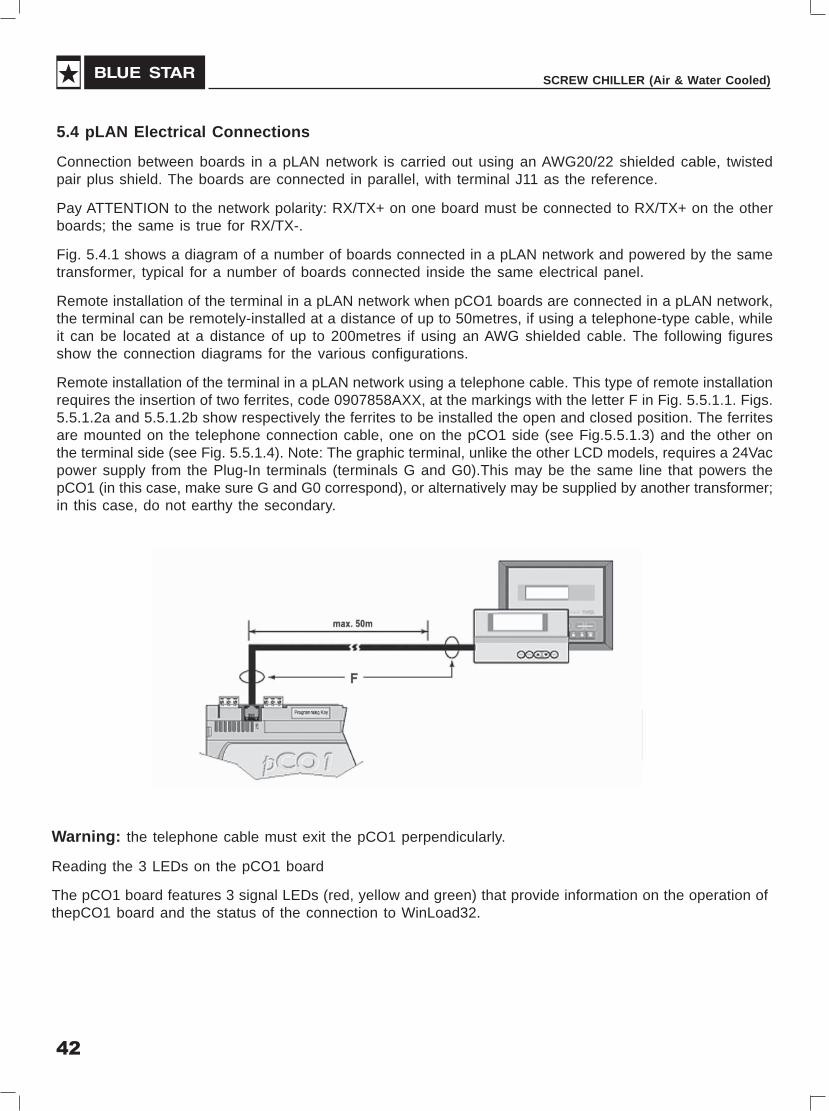
Remote installation of the terminal in a pLAN network when pCO1 boards are connected in a pLAN network,the terminal can be remotely-installed at a distance of up to 50metres, if using a telephone-type cable, whileit can be located at a distance of up to 200metres if using an AWG shielded cable. The following figuresshow the connection diagrams for the various configurations.
Remote installation of the terminal in a pLAN network using a telephone cable. This type of remote installationrequires the insertion of two ferrites, code 0907858AXX, at the markings with the letter F in Fig. 5.5.1.1. Figs.5.5.1.2a and 5.5.1.2b show respectively the ferrites to be installed the open and closed position. The ferritesare mounted on the telephone connection cable, one on the pCO1 side (see Fig.5.5.1.3) and the other onthe terminal side (see Fig. 5.5.1.4). Note: The graphic terminal, unlike the other LCD models, requires a 24Vacpower supply from the Plug-In terminals (terminals G and G0).This may be the same line that powers thepCO1 (in this case, make sure G and G0 correspond), or alternatively may be supplied by another transformer;in this case, do not earthy the secondary.
Warning: the telephone cable must exit the pCO1 perpendicularly.
Reading the 3 LEDs on the pCO1 board
The pCO1 board features 3 signal LEDs (red, yellow and green) that provide information on the operation ofthepCO1 board and the status of the connection to WinLoad32.

43
USER'S MANUAL
Key
� LED off �LED on �LED flashing

44
SCREW CHILLER (Air & Water Cooled)
*: Cases in which pCO1 reverts to Low Level status:
- When starting the pCO1 detects that Win Load is connected.
- When starting the pCO1 detects “Application corrupted…”.
- During normal operation the pCO1 runs a JUMP atom without the correct reference or backwards.
After 20 seconds of Low Level status without Win Load connected, the pCO1 is automatically reset.
• If the pCO1 is started with the key inserted and the key switch is set to Key (see Fig. 6.1.1), (SELECTIONLED red ), without pressing the buttons on the local terminal, the program resident in the key is run,without modifying the program resident in the pCO1.
In practice, the pCO1 controller can run an alterative program and/or setup to the resident version. Thisfunction is useful for testing upgrades to the BIOS and/or APPLICATION, without overwriting the softwareresident in the pCO1. It is also very useful for running special functions or parts of programs (e.g. finalfunctional tests) using special parameter
Configurations and/or programs (expressly developed for these functions), without modifying the programresident in the pCO1.Only the program and/or parameter configuration resident in the key are modified.Once this phase is complete, switch off the pCO1 controller, remove the key, and when starting the pCO1the next time, the original program and setup are used.
• If, on the other hand, the key switch is set to pCO1 (SELECTION LED green) and the buttons on thelocal terminal are not pressed, the key has no effect.
• To display or modify the pLAN address, use the local terminal: switch off the pCO1, remove the terminalfrom the pLAN network, connect the user terminal with address set to 0, start the pCO1 and hold theALARM and UP buttons until the screen is displayed showing the pLAN address, then follow theinstructions on the screen.
• The current version of program can be checked at any time (by CRC code expressed in hexadecimal),and whether the program on the key or the resident program is used. To check this, simply proceed asfollows.
Press the alarm and enter buttons together for 3 seconds, and the following screen will be displayed:
Confirming with enter displays a second table, as shown in the following example:
45
USER'S MANUAL
1st row BOOT: version and date. The pCO1 is working with BOOT 2.05, 24/01/02
2nd row BIOS: version and date. The pCO1 is working with BIOS 2.40, 20/02/02
3rd row Flash ON BOARD and KEY, if present. The characters (>_<) indicate the pCO flash: to the left ifthe pCO1 is booted
From the flash ON BOARD (switch on )and SELECTION LED red green ), or to the right if the
pCO1 is booted from the key (key switch on Key and SELECTION LED red ). In the example, the
pCO1 is running the BOOT, BIOS and application present ON BOARD, and has a 2MB key inserted.
4th row APPLICATION: CRC and flash occupied. the application CRC Is FA90 and requires a memory of1MB to be run. If this row shows the indication 2MB, a pCO1 with 2MB is required.
Exit these two screens by pressing the menu button on the local terminal, or automatically by timeout afteraround 40 seconds.
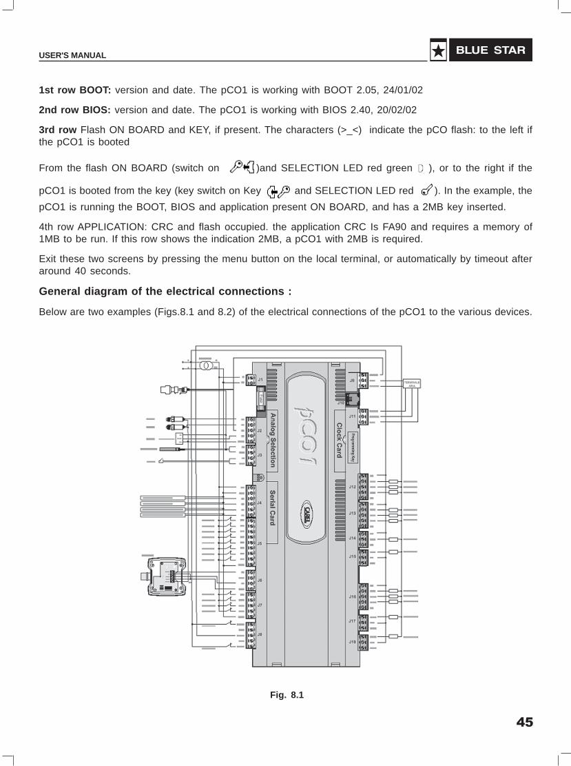
General diagram of the electrical connections :
Below are two examples (Figs.8.1 and 8.2) of the electrical connections of the pCO1 to the various devices.
Fig. 8.1

46
SCREW CHILLER (Air & Water Cooled)
pCO1pCO1 Medium (18 Din modules)
I/O Expansion Board Led Indication
Fig. 12.12

47
USER'S MANUAL
ConstructionHANBELL semi-hermetic twin-screw compressors are constructed with the following three major
components; the compressor compartment, the hermetic motor compartment and the oil separatorcompartment.
The compressor compartment includes twin-screw helical rotors, bearings and components for capacitycontrol system.
The hermetic motor compartment includes the motor stator, motor rotor, six terminal plugs for electric powerconnections, an internal thermostat inserted into the stator coil to protect the motor from burning out, twoterminal plugs for the thermostat, and a suction gas strainer.
The oil separator compartment consists of demister and chambers to serve as an oil separator and an oilreservoir. The rotor of the hermetic motor is connected directly at the suction end of the male rotor shaft anddrives the rotor shaft at rated speed of 2,950 rpm at 50 Hz and 3,550 rpm at 60 Hz respectively.
Screw Compressor

48
SCREW CHILLER (Air & Water Cooled)
Fig. 1 Construction of Screw Compressor
1. Compressor casing
2. Motor casing
3. Oil separator
4. Motor rotor assembly
5. Motor stator assembly
6. Motor rotor washer
7. Motor rotor spacer ring
8. Oil Separator Baffle
9. Oil separator cartridge
10. Piston
11. Piston spring
12. Piston rod
13. Bearing set’s cover plate
14. Modulation solenoid valve
15. Modulation slide valve
16. Slide valve key
17. Discharge bearings
18. Discharge fixed ring
19. Disc spring
20. α Balance piston
21. Bearing slot nut
22. Male rotor
23. Suction bearings
24. Suction bearings inner/outerspacer ring
25. Oil guiding ring
26. Oil level sight glass
27. Oil filler cartridge
28. Suction filter
29. Oil heater
30. Refrigeration Lubricant
31. Suction flange
32. Discharge flange
33. Cable box
34. Power bolt
35. Thermostat terminals
36. Motor cable cover plate
49
USER'S MANUAL
Capacity Control SystemThe BSC (RC) series screw compressors are equipped with 4-step capacity control system. The capacitycontrol systems consist of a slide valve, piston rod, cylinder, piston and its rings. The slide valve and thepiston are connected by the piston rod. The principle of operation is using the oil pressure to drive the pistonin the cylinder. See Fig 2.2 , The lubrication oil flows from the oil tank through the oil filter cartridge and capillaryand then fills into the piston cylinder due to the positive oil pressure higher than the right side of spring forceplus the high pressure gas. The positive pressure differential causes the piston to move towards the rightside within the cylinder. When the slide valve moves towards the right side, the effective compression volumein the compression chamber increases. This means the displacement of refrigerant gas also increases asa result to achieve higher refrigeration capacity. However, when any of the step solenoid valves is energized,the high pressure oil from the piston cylinder bypasses to the suction port to cause the piston with pistonrod link for the slide valve moving towards the left slide, then some of refrigerant gas by passes from thecompression chamber back to the suction end. as a result, the refrigeration capacity decreases owing tothe reduction in displacement of refrigerant gas flow in the system.
The piston spring is used to force the piston back to its original position, i.e. 25% position in order to reducethe starting current while the next startup. If the compressor starts at full load, will result in larger startingcurrent which could damage the compressor motor. The capillary is used to maintain and restrain a stableamount of oil flow to the cylinder.
If there is any oil filter cartridge, capillary, or modulation solenoid valve malfunction in the capacity controlsystem, will result in the abnormal operation of the capacity control system.
4-step capacity control system (See FIG 2.2)
There are three solenoid valves equipped on compressor that control the compressor capacity from deadstop (25%) to full load (100%). They are 25% capacity, 50% capacity, 75% capacity and 100% capacity. Thereare three normally closed solenoid valves that are used to control the various required in the capacity. Forthe compressor if selected for 4-step capacity control system, it is usual to be used with the sequence of25%-50%-75%-100% to load the capacity of compressor and to be used in sequence of 100%-75%-50%to unload the capacity. If 25% capacity is essential to be kept running for a long time, the problem of oil returnand motor cooling and high discharge temperature etc should be considered by adding the accessories suchas liquid injection devices.
a. 25% capacity
When solenoid valve of SV1 is activated, the high pressure oil in the cylinder bypasses directly to thesuction port, so the piston be held at its initial position. Be sure to take 30 seconds at least after everystarting the compressor at this low capacity stage. After that, the compressor could be loaded gradually.
b. 50% capacity
When solenoid valve of SV3 is energized by the temperature controller and also de-energized of 25%(SV1) solenoid value simultaneously, the high-pressure oil in the oil tank flows into cylinder due to theclosure of 25% valve that pushes the piston towards the position where a hole is provided which alsodrains the oil back to the suction port at exactly 50% position in case the piston holding there..

50
SCREW CHILLER (Air & Water Cooled)
c. 75% capacity
When solenoid valve of SV2 is energized, the 75% capacity solenoid valve will perform the same way asthe above b. 50% capacity illustrated.
d. 100% full load
When all the two/three modulation solenoid valves are de-energized, the high-pressure oil flows into thecylinder continuously to push the piston toward the right side gradually until the slide valve touches theend side in the compressing chamber and the piston also reaches its dead end entirely where no bypassof compression gas occurs. Hence full load is achieved.
Step Capacity Control System
No. Component No. Component
1 Suction fiilter 10 Lubricant
2 Gas in low pressure 11 Oil separator cartridge
3 Motor 12 Gas out (high pressure without oil)
4 Oil filter cartridge 13 Capillry
5 Suction bearings 14 Solenoid valve (25% of full load),SV1
6 Male rotor 15 Solenoid valve (50% of full load),SV3
7 Discharge bearings 16 Solenoid valve (75% of full load),SV2
8 Discharge silencer 17 Slide valve
9 Gas out high pressure with oil

51
USER'S MANUAL
LubricantThe main functions of the lubrication oil in screw compressor are lubrication, internal sealing, cooling andcapacity control. The positive oil pressure in the cylinder pushes the piston and the slide valve, which isconnected by a piston rod to move forward and backwardin the compression chamber. The design withpositive pressure differential lubrication system in the BSC series is available to eleminate an extra oil pumpin the compressor.
The bearings used in BSC compressor require a small but steady quantity of oil for lubrication; the oil injectioninto the compression chamber creates an oil sealing film in the compression housing for increasing theefficiency and absorbing a portion of heat of compression.
In order to separate the oil from the mixed refrigerant gas, an oil separator is required to ensure the leastamount of oil carried into the system. Pay more attention to the oil temperature, which is a very significantfactor for the compressor bearings’ life. High oil temperature will reduce the oil viscosity and cause poorlubrication and heat absorption in the compressor as well. It is recommended to keep the oil viscosity above15mm2/s at any temperature. If the compressor is operated under the critical conditions, (high dischargepressure) then extra oil cooler is required. Some high viscosity oil is recommended for applications with highworking condition. It happens often that the return oil from the evaporator is insufficient due to the high viscosityof oil, which is difficult to be carried back, that causes the loss of oil in compressor. If the system encountersthe oil return problem then it is recommended to install extra 2nd oil separator between the compressordischarge connection and condenser.
Each of BSC series of compressors are equipped with two oil sight glasses as a standard; one is the oilhigh level sight glass and the other is the oil low level sight glass. The normal oil level in the compressor oiltank should be maintained above the top of the low oil sight glass and in the middle level of high oil sightglass when compressor is running. It is recommended strongly to install the optional accessory of oil levelswitch to prevent from low oil level in compressor.
Warnings:a. Use specified oil and do not mix with different brands of oil. Different kinds of refrigerant should
match with different kinds of oil. Note that some synthetic oils are incompatible with mineral oil.Prior to fillery oil in the compressor, the system should be totally cleaned up during the initial startupand ensure that it is clean completely.
b. For the chiller system using synthetic oil, avoid the exposure of oil to the atmosphere too long, itis also necessary to vacuum the system completely when installing the compressor.
c. The table below shows the oil replacement standard. Each compressor at HANBELL chargesstandard quantity of oil.
d. In order to take out the moisture from the system, it is suggested to clean the system by hot air orNitrogen, thereafter vacuum the system as long as possible. It is essential to change new oil intothe system especially after the motor burn out, the acidic debris will still remain inside the system,hence follow the above mentioned procedures to overhaul the system. Check the oil acidity after72 hours operating and then change it again and again if the limit is still over the oil acidity standarduntil been qualified.

52
SCREW CHILLER (Air & Water Cooled)
Oil Replacement Standards
Item Value Item Value
Color, ASTM Above 6.0 Total acid number Above 0.5mg KOH/g
Particle Matters mg/100ml Above 5.0 Copper Strip 100oC/3hrs Above 2.0
Viscosity 40oC Variation ±10% of Moisture ppm Above 100
15mm2 / Sec or more
Changing oilLubrication oil is the most important factor to maintain the operating, lubricating, cooling, sealing and drivingthe capacity piston of the compressor. Following are the probable problems existing in the system that shouldbe faced:
1. Contamination of oil by debris causes clogging in the oil filter.
2. Acidified system due to the moisture causes corrosion in the motor.
3. Spoiled oil due to the compressor running at long duration of high discharge temperature reduces lifeof bearing.
Refer to the following oil change intervals to ensure normal running of the compressor.
1. Change the oil periodically: Check the oil for after every 10,000 hours of running periodically for thefirst operation cleaning of filter and oil change is recommends after 20,000 hours of operation hours isrecommended. Due to the piping debris could be accumulated inside the system after operation, checkthe oil after 2,500 hours or after one year of running. Check the system whether clean or not and thenchange the oil after every 20,000 hours or after 4 years running while the system is operated undergood condition.
2. Prevent debrics from getting clogged in the oil filter. Clogging can cause fearing failure. Installing anoptional oil pressure differential switch is recommended an optional oil pressure differential switch isrecommended to be installed. The switch will trip when the oil pressure differential reaches the setpoint between the primary and secondary sides and the compressor, will shut down to prevent thebearings damage to bearingsdue to lack oil.
3. If the compressor discharge temperature often keeps high approaching to the set point, then the oilwill be spoiled gradually in short time, hence check the oil characterestic every 2 months if possible.It is necessary to change the oil if the character of the oil is out of the standard. In case oil characteresticcould not be checked periodically, then change the oil after 4 years’ of installation or after 20,000 hours’of running which reaches first.
4. Acidity in lubrication oil shortens life of bearing and motor. Check the oil acidity periodically and changethe oil if the oil acidity value measured is lower than PH 6. Change the deteriorated drier periodically ifpossible to keep the system dry. Check the acidity of oil after 72 hours of initial of operation.
53
USER'S MANUAL
5. Refer to the oil changing procedures especially after the system overhaul owing to the motor burn out.Check the oil monthly or periodically and change the oil if it is if bad quality, it is necessary to take careof the oil quality and system cleanness and dryness in the system periodically.
The Compressors are charged with Blue Star ACS oil for the Air Cooled and Water Cooled Applicationand for R22
Liquid injectionThe liquid injection to the suction side of the compressor, is carried out by providing a separate thermostaticexpansion valve in the system. (Low-temp type expansion valve) The flow of liquid refrigerant is controlledthrough the expansion valve by the suction superheat directly.
Application of liquid injection :
The compressor motor temperature and its compression chamber temperature will be very high almostapproaching the setting of motor thermister and discharge temperature thermister, which often result in thetrip of the sensors under the above working conditions causing the chillers to shut down.
The purpose of installing a liquid injection system is to prevent the compressor motor from overheating, anexpansion valve is installed in the system with tube piped between the liquid line and compressor for coolingdown the compression chamber and motor to ensure that the compressor can be run continuously and safely.
The suction superheat should be controlled between 5 to 10 deg.C for the application of water cooled screwchillers by means of the expansion valve devices. During the initial start up, the loading of the chillers will beheavy due to the higher temperature of return chilled water, hence the liquid injection devices of adequatecapacity should be selected to reduce the overheat of the compressor.
When the compressor is operated for low temperature system (E.T=< -10 deg. C), the compression ratiowill be high at this condition and also the discharge temperature. Hence the use of liquid injection system isessential.

54
SCREW CHILLER (Air & Water Cooled)
Prior to starting of the unit, check up the procedure detailed herein
Items
Accessories
ElectricalSystem
Piping system
Safety devices
Things to be checked
1. Oil level
2. Time for heating the oil
3. System valve status.
4. Capillary
1. Voltage of the main power.
2. Voltage of the controlcircuit.
3. Insulation Resistance valueof the motor between phaseto phase and phase toground.
4. Power terminals and wirecables terminal connections.
5. Earthling
6. Settings of switches,sensors and controllers.
1. External piping
2. Leakage test
3. Compressor fixed tightlyLeakage test
1. Motor winding sensor
Discharge temp. sensor
Standard Values
1. Higher than the middleline of oil level sightglass.
2. Turn on the oil heater atleast 8 hrs. before starting.
3. Opened
4. No distortion or damage
1. Electricity voltage should bekept within +_15% to therated voltage. Instantmaximum voltage drop whilestarting should be less than10% to the rated voltage.
2. Standard voltage is 220 V.Maximum voltage is 230 V.
3. Insulation resistance valueshould be above 5 M ohms
4. Power terminals are firmlyfixed on terminal block andwell insulated. Keep wirecables away from heatsource and sharpened metal.Terminal screw and block,both are required.
5. As per local Electricityregulations.
6. Properly set.
1. Fixed properly
2. No leakage
3. Check up the tightness
1. Connected properly
2. Connected properly
Pre-Startup, Testing,Commissioning & Operation
S.No.
1.
2.
3.
4.
55
USER'S MANUAL
Pre-Start Up1. In addition to above pre start-up check up, it is also necessary to pay attention to the auxiliary facilities
while the chiller is commissioned at the job site and the periodic maintenance after the initial start up.
2. In order to keep the capacity control smoothly under the low ambient temperature with the normal viscosityof oil, it is required to heat the oil by heater at least 8 hours before next starting. The lower the ambienttemperature is, the longer the time of heating of oil should be. The oil temperature should be over 50Deg.C before starting the compressor. Keep the oil heater energised after the compressor is shutdownfor preparation of next start-up, to keep the oil temperature over the minimum required value, which isessential especially under low ambient condition.
3. Recheck the settings on each controls
4. Establish the chilled water flow through the cooler. Adjust the water flow rate to the designed rated flow.Connect the Chilled water flow switch with Micro Control Panel.
5. Establish flow through the water cooled condenser (for water cooled chillers). Adjust the flow rate to thedesigned rated flow. Connect the condenser water flow switch with the control panel.
5. Check if all the stop valves in the system are already opened
6. Check if the setting on each timer relay is correct.
7. Check up the idle pressure of the system
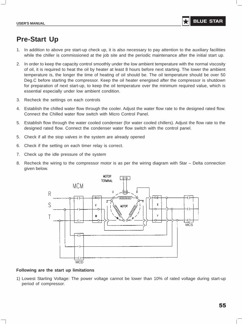
8. Recheck the wiring to the compressor motor is as per the wiring diagram with Star – Delta connectiongiven below.
MCD
MCS
Following are the start up limitations
1) Lowest Starting Voltage: The power voltage cannot be lower than 10% of rated voltage during start-upperiod of compressor.

56
SCREW CHILLER (Air & Water Cooled)
Starting Current of the compressorThe starting current of different model compressor is as given below (LRA). This will be approximately 3.0to 3.5 times the rated current.
Compressor Model Locked Rotor StartingCurrent (LRA), A Current A
BSC-075A 685 230
BSC-105A/ BSC-110W 735 245
BSC-130W 965 325
BSC-145A/ BSC-155W 1100 370
BSC-160A/ BSC-170W 1480 495
BSC-210A/ BSC-220W 1760 590
A. The starting for the Y start is usually set at 4 ± 1 second, and the maximum allowable shift time fromY to ∆ is 40 milliseconds. It is advisable to change the Y starting time prior to different working conditionin the job site in accordance with the current variation of Y starting. It is recommended that the durationof Y starting is not over 15 seconds at the step of 25% capacity.
2) Maximum Discharge Pressure: 18 kg/cm2 g
3) Minimum Suction Pressure: 6~8 kg/cm2 g
4) Maximum designed discharge pressure: 28 kg/cm2 g
5) Maximum designed discharge temperature: 110 Deg. C

57
USER'S MANUAL
The running restraint of compressor1. Compressor restart frequency
The restart counts for the models BSC - 077W, BSC - 105W, BSC - 145W, BSC - 160W and BSC- 210W are recommended below 6 times in one hour
2. The starting for the Y start is usually set at 4 + seconds and the maximum allowable shift time fromStar to Delta is 40 Sec. However it is recommended that the duration of the Y starting is not over 15seconds at the step of 25% capacity.
3. Supply power
Long term running => +15%
Instant Running => +10%
Frequency : +2 %
Phase current unbalance: The difference in phase current between the biggest phase current differentialand smallest phase current differential is required to be less than 3 %
4. Phase voltage unbalance: +2.25 %
5. Range of ambient temperature: -10 Deg. C to 55 Deg. C
6. The control voltage is normally 220 V
7. Protection switch
The table below shows the list of protection switches, which are essential to protect the compressor andoperate safely
Protection Switch Set Point
Motor winding Cut out 120 Deg. C
temperature protector Cut in 75 Deg.
High discharge Cut out 110 Deg. C
temperature protector Cut in 60 Deg. C
Phase reversal protector Phase reversal when power on
Hi – Low pressure protector Highest pressure 25 Kg/Sq.cm g
Phase failure protector Phase failure when compressorstarting or running
Motor overload relay Set by a related applicationvalue, any setting should betripped in 15 sec.
Hi-Low Voltage protector Rated Voltage + 15 %
Oil level switch Oil level lower than thefloating ball

58
SCREW CHILLER (Air & Water Cooled)
Operation of Micro ControllerThe control circuit for the Chiller comprises of analog sensor inputs such as suction pressure(s), dischargepressure(s), entering and leaving water temperatures etc. and digital sensor inputs such as flow switch, oillevel switch, SP/PR faults; etc. It consists of relay outputs that drive the compressor(s), condenser fans,economizer(s) etc.
Before switching ON the Screw chillier, ensure that the flow switch is connected between points 7 & 8 (and7A & 8A for twin cooler models) in the wiring diagram and there is sufficient water flow. The crankcase heatershould be ON for a period of min. 8 hours. In the OFF state, the condition of the outputs is as follows (providedincoming power supply is ON):
Relay output Condition
Main 1, 2 OFF
Load/ Unload sol (SV1)1/2 OFF
Load/ Unload sol (SV2)1/2 OFF
Load/ Unload sol (SV3)1/2 OFF
Pilot Solenoid valve 1, 2 OFF
Liquid Injection 1, 2 OFF
Economiser * OFF
Oil Cooler Fan * OFF
Condenser Fan A,B,C etc. * OFF
*Applicable only for Air Cooled Screw chillers
(1) Switch on power supply through Rotary Switch (mounted in control section). The unit goes in power upmode. In this state, all relay outputs are turned OFF. Controller will initialise & monitor Power Supplystability for 90 seconds.
Switch ON individual system toggle switches (mounted in control section) to enable demand forrespective compressors.
(2) After the power up delay, the system goes in ON state. Controller checks for any anti-cycle (fault) timersleftovers and then generates demand for the first compressor based on set point and actual chilled watertemperature.
(3) All three Solenoid Valve (SV1, SV2, and SV3) are kept de-energised after initial power up delay to ensureunloaded start of compressor.

59
USER'S MANUAL
Relay output Condition
Main 1, 2 ON
Load/ Unload sol (SV1)1/2 OFF
Load/ Unload sol (SV2)1/2 OFF
Load/ Unload sol (SV3)1/2 OFF
Pilot Solenoid valve 1, 2 ON
Liquid Injection 1, 2 OFF
Economiser * OFF
Oil Cooler Fan * OFF
Condenser Fan A,B,C etc. * OFF
*Applicable only for Air Cooled Screw chillers
(5) One bank of condenser fans goes ON with corresponding compressor. (Applicable in case of Air CooledChillers)
(6) Depending on difference between the leaving water temperature and set point, the system shall load orunload. The operation of the load or unload solenoid valves is as under for individual compressor
Sl. No. Capacity Control System SV1 SV2 SV3
1 100 % Of Full Load On On On
2 75 % Of Full Load On Off On
3 50 % Of Full Load On On Off
4 25 % Of Full Load Off On On
5 Shut Down and Initial Fast Unloading Off Off Off
(7) When compressor-1 is at 100% load (or unable to load further due to safety hold), demand for the secondsystem is generated to meet further load.
(8) The 1st Compressor unloaded to minimum 50% slide position and 2nd compressor is started as per thesequence given in steps 4 to 6
(9) Thereafter both compressors are loaded / unloaded simultaneously .If load goes below 50 %, onecompressor will switched off and other will utilizes the available full capacity. (Unless any of thecompressors goes in safety hold).
(4) Compressor starts with ‘Fast Unload’ logic. Condition of the relay outputs is as follows:

60
SCREW CHILLER (Air & Water Cooled)
Shut down sequence
• To shut down complete chiller switch off rotary switch provided in panel. To switch OFF a particularcompressor, respective toggle switch should be switched off.
• During normal shut-down through controller, Compressor runs for preset time to enable unloadingof slide to minimum position before switching OFF
• Run Time Equalization
Controller has ‘minimum run time equalization’ logic option (set point 103 should be 0 and set point 104 shouldbe 1). Compressor which runs for minimum time shall start first during next operation cycle.
Safety Parameters
During normal running of compressor (s) following safety Parameters are monitored :
Sr. No. Set Point Description Trip Delay (Seconds) Default Setting
1 Hi amps 2 105 %
2 Low amps 5 15 %
3 Low suction 120 20 psig
4 Low gas / LSV FLT 10 15 psig
5 High discharge 2 250/375 psig
6 Low discharge 90 80 psig
7 Low oil differential 180 50 psig
8 Unsafe Oil 4 20 psig
9 Anti freeze * 5 39oF
* In case of Anti Freeze, all the Circuits of the entire Chiller are locked out.

61
USER'S MANUAL
Operating Specifications
The following are the Operating Specifications and default set points:
1. Leaving water temperature is set at 45ºF with a control of ±0.5ºF.
2. Liquid injection system switches ON at Discharge Temperature of 165ºF and switches OFF atDischarge Temperature of 155ºF.
3. The Economizer Solenoid Valve activates at 75% of Slide positions and turns off at 65% of slideposition. (Applicable for air cooled chillers only)
4. One bank (50% of the total No. of fans) of condenser fans switches ON at discharge pressure 200psig and turns OFF at 140 psig. (Applicable for air cooled chillers only)
5. The delay between the Star and Delta connection is preset at 3 seconds.
6. Low-pressure setting is at 15 psig and High-pressure setting is at 250 /375 psig.
7. Anti Freeze Thermostat setting is at 39ºF
To avoid nuisance tripping during compressor start up, following initial by pass / time delay adjustmentprocedure is observed.
Set Point Description Bypass Time Delay Adjustment*
Hi amps For first 3 seconds —
Low amps For first 3 seconds —
Low suction During pump down
Low gas / LSV FLT — 2 Min for 30 PSI
Low oil differential First 5 seconds 25 psig for next 30 seconds.
Oil Level Switch First 1 Minute —

62
SCREW CHILLER (Air & Water Cooled)
1. Capacity Control Method
The capacity control method is based upon to develop the control zone on both side of Water leavingtemperature set point, and accordingly add or subtract the capacity control stages of chiller. To accomplishthis system will constantly monitor the set point, trend of load and slide position in relationship to the controlzone.
1.1 Common Definitions
1.1.1 Target
The control target is “Water Leaving Set point”. This will be the base of developing the control zone.
1.1.2. Control Zone
The control zone is developed by adding the set points for the control target and the dead band + to obtainthe upper limit. The lower limit is obtained by subtracting the dead band - set point from the control target
Once the control zone has been established, the system will attempt to keep the control sensor readingwith in this range. The capacity control stage calculation is in hold if the chiller running in control zone.
1.1.3. Controlling Sensor
This is the sensor that has been specified as leaving temperature.
1.1.4. Trend of Load
The Trend of Load is how fast the control value is changing over a period of time. If the control value isincreasing the rate will be positive, if decreasing the rate will be a negative value. How fast the input ischanging, its direction and where the current input reading is in relationship to the control zone will determinewhat action the system will take.
1.1.5. Slide Valve Countdown
The system will not attempt to take action until the Slide Valve Count down reaches zero. The speed thatit is decrement by is based upon the Trend of Load of control input value and the slide Response that hasbeen specified.
1.1.6. Slide Response
The purpose of the Slide Response value is to limit or dampen how fast the slide reacts to changesindicated by the control sensor. The lower the number, the faster the system will react to changes of thecontrol sensor.
The Control Status portion of the Status screen is shown below.
Chiller information:
• Capacity Control State - State of chiller
• TIME - time in that state, if the state is UNIT IN POWER UP time will decrement to zero
• Steps wanted / Steps Actual On - Number of steps wanted on verses the actual steps turned onverses the total steps on the chiller.

63
USER'S MANUAL
• Slide Valve Countdown - value that is counted down. The Slide Response and where the controltemperature is in relationship to the control zone will determine the speed of the count down.When the value decrements to zero, the system will determine if a change in the systemscapacity is required.
• Wanted Slide % - Wanted slide percentage
• Trend Of Load – Trend Of Load of control sensor, the speed at which the control sensor ischanging.
Circuit information (all active circuits will be displayed):
• Circuit Number and State - Circuit number and state.
• TIME - time in that state, if the state is CMP ANTICYCLE time will decrement to zero.
• Oil Diff - Oil differential pressure. Oil differential pressure is calculated as follows:
Semi hermetic screws; Oil psi – Suction psi or Discharge psi – Suction psi.
• Lead - indicates the lead compressor.
• FLA %: Full Load Amps based on the set point.
2. Capacity Control State
Capacity Control States are active for all five releases of software.
UNIT IN POWER UP
This state is entered when the Controller is powered up or the system has been reset. The system willremain in this state for the time specified in set point POWER UPDELAY, set point 23, or if not active for60 seconds. In this state all points (RO’s) are turned off. This is a time delay to insure the controller hasstable power before starting the algorithm.
UNIT IN LOCKOUT
This state is entered whenever a critical situation is encountered that could cause harm to the chillerpackage. Items such as freeze protect and emergency stop will force the system into this state.
Lockouts can be reset with user level authorization from the keypad; however if the lockout condition hasnot been corrected, the system will again be forced into the LOCKOUT state.
NOTE: If the Lockout reset is pressed more than 10 times in a day the unit cannot be reset till Factoryauthorization.
EXPANSION BOARD OFFLINE
This state will be entered whenever the controller loses communications with any of the I/O boards that areconnected via the network. When this state is entered the system will generate an off line alarm, whichlocks out the unit. The lockout-reset key must be depressed to reset the system, after the lost I/O has beencorrected.

64
SCREW CHILLER (Air & Water Cooled)
SWITCHED OFF
This state is entered when the run stop switch is off, in the stop position. When the chiller is in this state,the individual circuit states if active are moved to the CMP IS OFF state through the normal states.
SCHEDULED OFF
This state is entered when the schedule is calling for the package to be off. When the chiller is in this state,the individual circuit states if active are moved to the CMP IS OFF state through the normal states.
OFF- NO EVAP FLOW
This state is entered when the evaporator flow switch is off. When the chiller is in this state, the individualcircuit states if active are moved to the CMP IS OFF state through the normal states. The controller willgenerate the alarm in this condition and not required to be reset if alarm is clear.
UNIT IS HOLDING
This state is entered when one of three conditions exists:
1. The control sensor reading is being maintained with in the control zone.
2. Control sensor reading is above the control zone but the Trend Of Load is less than the value inthe set point. This indicates that the temperature is decreasing toward the target at an acceptablespeed. Therefore, no additional cooling is needed at this time.
3. The temperature is below the control zone but the Trend of Load is greater than the set point. Thisindicates that the temperature is increasing toward the target.Therefore, no reduction in cooling isneeded at this time.
This state indicates that there is no need to adjust the cooling capacity of the chiller package. Thisstate will be exited when more or less capacity is required.
3. Circuit Control States
The action of the circuit control states actually result in more, less or no change in the amount of coolingcapacity. The CAPACITY CONTROL STATES dictate how the individual circuits move within their states.
CMP LOCKED OUT
This state is entered when the Capacity Control State is LOCK OUT or a safety set point for this circuithas indicated that a critical situation has been encountered. Set points such as LOW SUCTION, HIDISCHARGE PRESSURE etc. are examples of safety set points. Lockouts can be reset with USER levelauthorization from the keypad; however if the lockout condition has not been corrected, the circuit will againbe forced into the LOCKOUT State.
SAFETY TRIPPED
This state is entered when a safety trips but a lockout is not to be generated. An alarm is generated butthe system will restart after the delay specified in the corresponding set point. If a second trip occurs withinthe time specified in the set point, the circuit will be placed in the CMP LOCK EDOUT State.

65
USER'S MANUAL
CMP OFF / READY
This state is entered when no cooling capacity is required from this circuit or the prior state was CMPANTICYCE, LOST IO LOCKED or SWITCHED OFF. In this state the circuit is ready to provide coolingcapacity if needed. The circuit will remain in this state for a minimum of 60 seconds.
CMP PMP DOWN
This state is entered whenever the pump down switch has been turned on or if this circuit is no longerwanted on. The compressor is on and the liquid line solenoid is closed. This state is active until the suctionpressure reaches the value in the set point PMP DWN DELAY. The circuit will then move to the ANTICYCState.
CMP ANTICYCLE
This state is entered when the PMP DWN State has been completed. The circuit will stay in this state withall circuit points off for the period of time contained in either set point “ANTYRECYCLE TIME “. The circuitwill then move to the OFF State.
FAST UNLOADING
For screw compressors, this state is entered when the compressor is turned on. The system will remainin this state for 60 seconds while the “fast unloader” and unload points are on. This is to ensure that thescrew is unloaded.
CMP IS HOLDING
This state only exists for infinite step compressors (Three solenoid valve SV1,SV2 & SV3 ). In this state,the required refrigeration capacity of system is being meant; no movement of the slide valve is required.
CMP IS AT 25%
This state is when the compressor is providing 25% of its capacity. In this state, the relay output to activatethe 25% valve is turned on.
CMP IS AT 50%
This state is when the compressor is providing 50% of its capacity. In this state, the relay output to activatethe 50% valve is turned on.
CMP IS AT 75%
This state is when the compressor is providing 75% of its capacity. In this state, the relay output to activatethe 75% valve is turned on.
CMP IS AT 100%
This state is when the compressor is fully loaded. In this state, the circuit is providing the maximum amountof cooling capacity.
66
SCREW CHILLER (Air & Water Cooled)
HI DISC UNLOAD
Refer to set points HI DISCH PSI, HI DISC UNLD, HI DISC RELD7 and HI DISCH TMP, HI DISCH UNLDand HI DISCH RELD.
This state is entered when a fully loaded circuit, that has more than one step, has encountered either adangerously high discharge pressure or discharge temperature. One step of cooling capacity will be turnedoff. The circuit will remain in this state for a minimum of five minutes before returning to the LOADED stateif the dangerous condition has been corrected.
When capacity is being held due to a high discharge condition, once the discharge goes to normal operatingcondition the circuit will return to its appropriate state.
LO SUCT UNLOAD
Refer to set points, LOW SUCTION, LO SUCT UNLD and LO SUCT RELD.
This state is entered when a fully loaded circuit, that has more than one step, has encountered a dangerouslylow suction pressure. One step of cooling capacity will be turned off. The circuit will remain in this statefor a minimum of five minutes before returning to the LOADED State if the dangerous condition has beencorrected. When capacity is being held due to a low suction pressure condition, once the suction pressurereturns to a normal operating condition the circuit will return to its appropriate state. This should be samefor “LOW GAS “
LO TMP UNLOAD
The circuits leaving liquid temperature have caused the system to unload. When the leaving liquid temperaturegets to within 1.5 degrees F of the Freeze set point, the unload will occur before we hit the freeze protectsafety.
HI AMP HOLD
This state is entered when a fully loaded circuit, that has more than one step, has encountered a dangerouslyhigh AMP draw. Refer to set points for FLA per circuit and HI AMPS %. In this state, one step of coolingcapacity will be turned off. The circuit will remain in this state for a minimum of five minutes before returningto the LOADED State if the dangerous condition has been corrected.
4. Condenser Control Logic
4.1 Condenser Fan Cycling Logic
The air condenser set points are as follows:
Set point CND STG1 ON - Condenser stage 1 cut in (ON).
Set point CND STG1 OFF - Condenser stage 1 cut out (OFF).
Set point CND DIFF ON - Differential between condenser stages for cut in (ON).
Set point CND DIFF OFF - Differential between condenser stages for cut out (OFF).
Set point CND MIN RUN - Minimum run time for a condenser stage when the discharge pressure reachesthis value the first condenser point is turned on. If additional condenser points exist, they will be turned onwhen the pressure exceeds the previous cut in value plus the value contained in (COND DIFF IN) set point.
67
USER'S MANUAL
As the discharge pressure is reduced, the condenser points will be turned off based upon the set point(COND ST1 OFF) value plus the condenser step times the value contained in (COND DIFF OUT) set point.The first step will be turned off based upon the valve in the set point (COND ST1 OFF).
Example Set point 45 CND STG1 ON = 200.0P
Set point 46 CND STG1 OFF = 170.0P
Set point 47 CND DIFF IN = 20.0P
Set point 48 CND DIFF OFF = 5.0P
COND FAN1 ON @ 200.0P DISCHARGE
COND FAN 1 OFF @ 170.0 P
COND FAN2 ON @ 220.0p (200.0 + 20.0)
COND FAN2 OFF @ 175.0p (175.0 + 5.0)
COND FAN3 ON @ 240.0p (220.0 + 20.0)
COND FAN3 OFF @ 180.0p (170.0 + 10.0), etc.
5. Set Point Definitions
5.1 SET POINT TYPES:
There are three different types of set points. The type determines the action that the system will take.
5.1.1. SET POINT
This type of set point’s value contains a target or provides information for some type of action. The timeelement in this type is not used
5.1.2. LOCKOUT
This type of set point’s value contains a safety level and the time that the safety must be violated beforethe safety will trip. Once a safety has tripped the system will take the appropriate action, shutting down theentire package or an individual circuit (compressor) depending on the purpose of the safety. The systemwill then wait the safety down time contained in that set point before trying to return the system to normal.If successful, the system will continue to operate. If a second trip occurs on the same set point with in thelock out delay time that is contained in that set point the system will move to a LOCKOUT state. IF THELOCKOUT DELAY TIME IS SET TO ZERO THE LOCKOUT WILL OCCUR ON THE FIRST TRIP. Thiswill require manual intervention to reset the system. With each safety trip, the system will generate analarm; refer to Alarms and Safeties section of this manual.
5.1.3. ALARM
This type is similar to the LOCKOUT set point except it will never cause a lock out. The system will continueto try to return to normal operation after waiting the safety down time. An ALARM set point type will neverrequire manual intervention to reset the system.
68
SCREW CHILLER (Air & Water Cooled)
6. Set Points for Chiller Controller Algorithm
6.1 Control set points
1. CTL TARGET Controlling target is used with the ctl zone & slope and is leaving liquid
2. CTL ZONE + Added to the CTL TARGET to create the top of the control zone.
3. CTL ZONE - Subtracted from the CTL TARGET to create the bottom of the control zone.
4. L.INJECT.ON Liquid injections is turned on when the discharge temperature is equal to or greaterthan this set point and turned off when the discharge temperature is less than this set pointminus 5.
5. POWERUP DELAY
This is the time that the system will remain in the START UP state before moving to the next state.
6.2 Capacity Control Logic
1 SLIDE RESPONCE This value is used to adjust the speed of responding to changes in the controlalgorithm. 1= faster response HIGHER number’s = slower response.
2 SLIDE VALVE COUNTDOWN This is the time delay before increasing or decreasing the numberof refrigeration steps.
3 MAX TREND OF LOAD - Maximum negative Trend of Load allowed before stopping the unit fromloading. If the actual ROC is less than this value the capacity control state is placed in theHOLDING state.
4 MAX TREND OF LOAD + Maximum positive Trend of Load allowed before stopping the unit fromunloading. If the actual ROC is greater than this value the capacity control state is placed in theHOLDING state.
5 TREND OF LOAD INTERVAL Number of second between the samples used for calculating theactual Trend of Load
6.3 Set Points for Compressor Control
1 ANTYCYCLE This is the anti cycle time delay (in seconds) based on when the compressor wasturned off. It will vary from compressor to compressor.
2 PMP Down Delay Maximum time delay (in seconds) that a compressor can remain in the PUMPDOWN state.
3 Comp Min Run this is the minimum run time (in minutes) for a compressor once it is turned on.This minimum run time is bypass only for the safeties.
4 FLA Comp#1 Full Load Amps for the compressor on circuit 1.
This value is used to calculate the high and the low ampere safeties limits.

69
USER'S MANUAL
6.4 Set Points for Compressor Safeties
1. HI AMPS : This set point is a percentage of the FLA; it is used to create the high amp draw limit.This value is tested in the high amp safety, if the amps exceed this value for the time specifiedin this set point the safety is tripped.
2. LOW AMPS : This set point is a percentage of the FLA; it is used to create the low amp drawlimit. This value is tested in the low amp draw safety, if the amps exceed this value for the timespecified in this set point the safety is tripped.
3. LOW SUCTION : If active, the system checks for low suction pressure for each running compressor.The system will compare the suction pressure sensor reading to this value. It must be less thanthe value for the period of time specified in the set point before this set point will trip.
4. LOW SUCT UNLOAD: The purpose of this set point is to take corrective action before a lowsuction pressure safety occurs. If a circuit has more than one step and it is fully loaded and if thesuction pressure is less than the value of the safety set point (LOW SUCTION) plus the value ofthis set point, the system will turn off one step of capacity.. The circuit state will be changed toLO SUCT HOLD. The circuit will remain in this state for a minimum of 5 minutes. At that time, ifthe suction pressure has increased to a level greater then the value of set point LOW SUCTIONplus the value of set point LOW SUCT RELD the compressor will return to normal control.
5. LOW SUCT RELD: The system will force to load if requirement ,if this setpoint is satisfied
6. UNSAFE SUCT : If active, the system checks for low suction pressure that is in an unsafecondition for each running compressor. The system will compare the suction pressure sensorreading to this value. It must be less than the value for the period of time specified in the set pointbefore this set point will trip. Note the time period specified should be very short, 2-5 seconds. Thissafety set point trips the circuit to the LOCKOUT state immediately, no retry.
7. HI DISC PSI : If active, the system checks for high discharge pressure condition for each runningcompressor. The system will compare the discharge pressure sensor reading to this value. It mustbe greater for the period of time specified in the set point before this safety will trip.
8. HI DISC UNLOAD : The purpose of this set point is to take corrective action before a highdischarge pressure safety occurs. If a circuit has more than one step and it is fully loaded and itsdischarge pressure exceeds the value of the safety set point HI DISCH PSI minus this set point,the system will turn off one step of capacity. A screw compressor will be forced to unload until thedischarge pressure falls below the calculated value. The circuit state will be changed to HI DISCHLD. The circuit will remain in this state for a minimum of 5 minutes. At that time if the dischargepressure has dropped below the value of the HI DISCH PSI minus the HI DISC RELD the compressorwill return to normal control.
9. HI DISC RELD : This set point works same as Low Suct Reld
10. LOW DISC PSI : If active, the system checks for low discharge pressure. The system willcompare the sensor reading to this value. It must be less than the value for the period of timespecified in the set point before a safety trip occurs.
11. HI DISC TMP : If active, the system checks for high discharge temperature condition for eachcircuit that has at least one step on. The system will compare the discharge temperature sensorreading to this value. It must be greater for the period of time specified in the set point before thissafety will trip.
70
SCREW CHILLER (Air & Water Cooled)
12. HI DISC UNLOAD : The purpose of this set point is to take corrective action before a highdischarge temperature safety occurs. If a circuit has more than one step and it is fully loaded andits discharge temperature exceeds the value of the safety set point HI DISCH TMP minus this setpoint, the system will turn off one step of capacity. A screw compressor will be force to unload untilthe discharge temperature falls below the calculated value. The circuit state will be changed to HIDISC HLD. The circuit will remain in this state for a minimum of 5 minutes. At that time if thedischarge temperature has dropped below the value of the HI DISCH TMP minus the HI DISCRELD the compressor will return to normal control.
13. HI DISC T RELD : This set point works same as LOW SUCT RELD
14. LOW OIL DIF : If active, the system checks for low differential oil pressure. The system willcompare the calculated differential oil pressure to this value. It must be less than the value for theperiod of time specified in the set point before the safety will trip.
15. UNSAFE OIL : If active, the system checks for low differential oil pressure. The system willcompare the calculated differential oil pressure to this value. It must be less than the value for theperiod of time specified in the set point before the safety will trip. The time delay for this set pointshould be very short 2-5 seconds. These safeties trips to a lockout no retry are attempted. Manualintervention is required.
16. HII OIL TEMP : If active, the system checks for high oil temperature. The system will comparethe oil temperature sensor reading to this value. It must be ON or greater for the period of timespecified in the set point before this set point will trip. The sensor can be either an analog or digitalinput.
17. SAFETY HOLD DELAY : Time in seconds to hold before trying to reload when the capacity hasbeen decreased to avoid a safety, (Examples: high disc psi, high disc temp, low suct psi, etc,)
18. LEAD COMP. Enables the user to specify the lead compressor.
19. COMP. ROTATION Specifies the number of days between rotation
6.5 Set points for Unit Safeties
111 FREEZE If active, the system checks for freeze protection. The system will compare the chilled waterout temperature to this value. It must be less than the value for the period of time specified in the set pointbefore this safety will trip.
6.6 Economizer Set Points
Economizer On % the set point at which Economizer will get ON
Economizer Off % the set point at which Economizer will get OFF
6.7 Oil Differential Calculation
The calculation is DISCHARGE PRESSURE minus SUCTION PRESSURE.
7. Authorization Function
The authorization code is a special four-character code that enables access in to the system. The codemust be numeric with values between 0 and 9if it is to be entered from the Keypad/Display.
This provides the capability of issuing different codes to different people if desired. There are four levelsof authorization, which provide different capabilities with in the system. The authorization code and the

71
USER'S MANUAL
associated level cannot be displayed in system. The authorization codes must be protected and remainconfidential, if they are compromised unauthorized personnel can gain access to the system. The two levelof safety has been provided
1. User level - Authorized to Change Water leaving set point within the Min & Max value, lockout resetand control zone
2. Factory Level - Authorized for rest of all the things
7.1 RESTORE FACTORY SETTING AND DATA LOGGING
7.1 .1 If some modification has been made in the program SETPOINT, the factory setting can berestored through the set point “Restore Factory Setting” at any movement.
7.1.2. Maximum 100 alarms can be stored with SP, DP and Current reading during trip. The last 20Dynamic reading with the interval of 1 second will also get stored which will updated with themention time interval.
8. On/Off Switches
The following digital input switches can be associated with the system, their action will affect the chillerpackage or an individual circuit, and then action will only affect that circuit:
• Flow switch, if off the system has lost flow. The system wills either lock out, if NO FLOW set pointis active, or shut down, if NO FLOW set point is inactive.
• Pump down switch, if on and the compressor is off, will not start the compressor. If the compressoris on, the system moves to the pump down state to begin the process of turning off thecompressor(s) in normal steps.
• Run/Stop, if off the system will not run. This is usually wired to a RUN/STOP switch that ismanually positioned. If the system is running, the system moves all circuits (compressor) to offin normal steps. (If a RUN/STOP and a Network RUN/STOP are both available they operate inseries.)
• Emergency Stop switch, if on, the system will be shut down immediately and will remain disableduntil the switch is off.
9. Operating Schedules
Two operating schedules per each day of the week and 8 holidays are supported. Each schedule containsa start and end time, if the time and day of the system is with in these limits the schedule is true and thesystem will be allowed to run. If not, the system will be off due to schedule.
10. Compressor
The compressor with the least number of TOTAL RUN HOURS will become the lead. Refer to Set points#103 & #104.

72
SCREW CHILLER (Air & Water Cooled)
11. Alarms and Safeties
11.1 Introduction
There are three types of alarms that are generated by the Carel control logic:
• Information only alarms,
• Controller system alarms and
• Chiller set point safety alarms.
All of the alarms have the same format. The alarm is identified and it is date time stamped. Alarms can beviewed from Carel controller by pressing the ALARM STATUS (4) key or from the PC-Connect Program.
Sensor inputs used in conjunction with Controller set point safeties:
11.1.1 Suction Pressure - Pressure transducer to read the suction pressure.
11.1.2 Discharge Pressure - Pressure transducer to read the discharge pressure.
11.1.3 Oil Differential Pressure - Calculated value of the oil pressure as follows:Screws without oil pump, discharge psi minus suction psi
11.1.4 Oil Temperature - Either a temperature sensor or a digital input that indicates when a hightemperature condition exists.
11.1.5 Discharge Temperature - Either a temperature sensor or a digital input that indicates when a hightemperature condition exists.
11.1.6 Motor Amps - Sensor input that measures AMP draw of the compressor. (Optional digital input)
11.1.7 Liquid Temperature - Temperature sensor that can be used to detect a freeze condition
11.1.8 Flow Switch - A digital input that indicates that flow through the chiller barrel exists. There can beone switch per chiller or one for each circuit.
11.1.9 Set point safeties - For a safety to be interrogated, both the associated sensor input and thelockout set point must be active. If a safety trips, the alarm name will consist of the set point nameplus additional identification such as point number or circuit number if applicable.
The system exercises “smart” safety testing in the following manner:
If a safety applies to a circuit and it is an active lockout type of a set point, the first time this safety tripsan alarm will be generated and the circuit will be shut down and placed in a safety state. The system willattempt to reactivate this circuit after waiting the length of time specified in this set point, safety down time.If successful the system will continue to run. If the same safety trips the time specified in the lockout delaytime, the circuit will be locked off and a manual intervention is required. If the lockout delay time is set tozero, the system will generate a lockout condition the first time that the safety occurs.
The time in the safety state and the time between safeties are specified in the individual set points.
This enables the times to be unique for each lock out set point.
Most safeties are checked only if the Compressor is running, if he safety is always checkedit will be so noted.

73
USER'S MANUAL
The following are a list of safeties that are incorporated in the standard chiller algorithm control. Thesesafeties are checked every second. Note, for a multiple circuit system, each circuit is tested individually.If a safety condition exists, action will be taken with that circuit only, other circuits will continue to function.
11.1.10 Freeze Protection (Safety is always checked)
If the leaving liquid temperature drops below the set point value the system, and all circuits, will enter alockout state and a freeze notification alarm will be generated. You have the option of one freeze protectfor the package or individual freeze protections by circuit..
11.1.11 No Flow Protection
If the flow switch is for the chiller system, then the entire system will be shut down and automaticallyrestarted when the flow switch is on, indicating that there is flow.
11.1.12 Phase Loss Protection
Phase loss, as indicated by the phase loss monitor, will result in the system and all circuits being lockedoff and a phase loss notification alarm will be generated. No set point is required.
11.1.13 Emergency Stop
Emergency stop, as indicated by the emergency stop switch, will result in the system and all circuits beinglocked off and an emergency stop notification alarm will be generated. No set point is required.
11.1.14 Low Differential Oil Pressure
This safety is designed to meet the compressor manufacturer requirements on oil pressure. For the first5 (60 seconds if setup as Hitachi screw compressors) seconds following a compressor start this safetyis NOT checked. For the next 30 seconds, if the oil differential pressure drops below ½ of the value of theset point or the digital input turns ON and it remains there for the time specified in the safety time of thatset point, the compressor will be locked out and a low oil alarm generated. After this time period, if the oildifferential pressure drops below the value of the set point
11.1.15 Low Suction Pressure
If the suction pressure drops below the value of the set point or the digital input turns ON and it remainsthere for the time specified in the safety time, the compressor will be locked out and a low suction alarmgenerated. For the first 5 minutes after the compressor has started the set point will be ½ , this enablesthe set point safety time to be set much tighter for normal operation.
This safety is bypassed when the compressor is in the “CMP PUMP DOWN” state. This safety can alsobe used as a freeze protection based upon the suction PSI.
11.1.16 Unsafe Suction Pressure
This safety is similar to the low suction pressure safety except this set point can be set up with a lowervalue and a very short safety time. If the suction pressure drops below the value of the set point or the digitalinput turns ON and it remains there for the time specified in the safety time of that set point, the compressorwill be locked out and a low suction alarm generated. This safety will always cause a lock out on the firsttrip requiring a manual reset to restart the compressor. For the first 5 minutes after the compressor hasstarted the safety time is extend by twice the normal time delay, this enables the set point safety time tobe set much tighter for normal operation. . This safety is bypassed when the compressor is in the “CMPPUMP DOWN” state.

74
SCREW CHILLER (Air & Water Cooled)
11.1.17 Low Discharge Pressure
If the discharge pressure drops below the value of the set point and it remains there for the time specifiedin the safety time of that set point, the compressor will be locked out and a low discharge alarm generated.
11.1.18 High Discharge Pressure (Safety is always checked)
If the discharge pressure rose above the value of the set point or the digital input turns ON and it remainsthere for the time specified in the safety time of that set point, the compressor will be locked out and a highdischarge alarm generated.
11.1.19 High Discharge Temperature (Safety is always checked)
If the discharge temperature analog input rises above the value of the set point or the digital input turns ONand it remains there for the time specified in the safety time, the compressor will be locked out and a hightemperature alarm generated.
11.1.20 HI Motor Temperature or Motor Fault (Safety is always checked)
If the high motor temperature input rises above the value of the set point or the digital input turns ON andit remains there for the time specified in the safety time, the compressor will be locked out and a high motortemperature or motor fault alarm generated.
11.1.21 Hi Oil Temperature
If the oil temperature rises above the value of the set point or the digital input turns ON and it remains therefor the time specified in the safety time of that set point, the compressor will be locked out and a high oiltemperature alarm generated.
11.1.22 Low Motor Ampere
If the ampere analog input drop below the value of the set point and it remains there for the time specifiedin the safety time of that set point, the compressor will be locked out and a low motor amp alarm generated.This alarm can be used to indicate low refrigerant. This safety is bypassed for the first 3 seconds after acompressor has started.
11.1.23 Oil Level Low
If oil level drop below the required minimum level, the controller will display the alarm as ‘Low Oil Level”.The safety will bypass for 60 minutes during running and 60 second during the start up of compressor.
12. Control States Quick Reference
Control States tell the user the system’s status; this information is critical. From the Carel keypad / display,press the menu key and select STATUS> The control status is the second line. Carel Control States QuickReference.
Control States tell the user the system’s status; this information is critical!
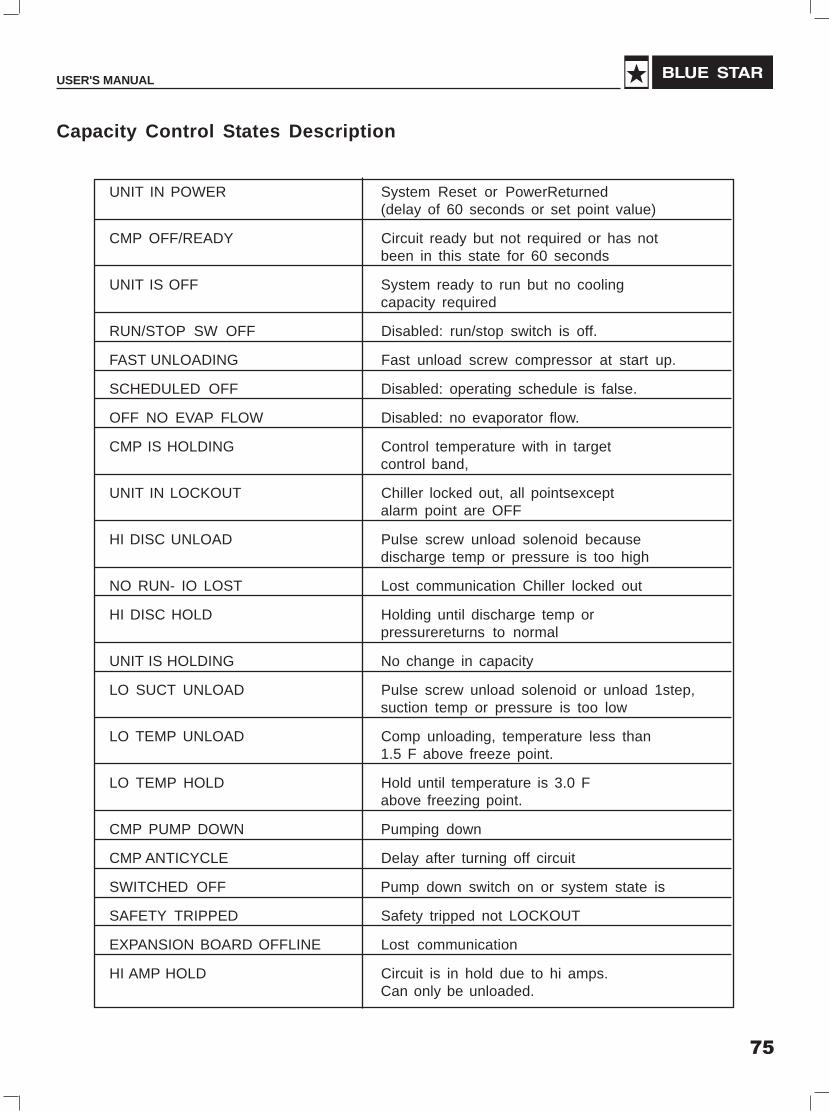
75
USER'S MANUAL
Capacity Control States Description
UNIT IN POWER System Reset or PowerReturned(delay of 60 seconds or set point value)
CMP OFF/READY Circuit ready but not required or has notbeen in this state for 60 seconds
UNIT IS OFF System ready to run but no coolingcapacity required
RUN/STOP SW OFF Disabled: run/stop switch is off.
FAST UNLOADING Fast unload screw compressor at start up.
SCHEDULED OFF Disabled: operating schedule is false.
OFF NO EVAP FLOW Disabled: no evaporator flow.
CMP IS HOLDING Control temperature with in targetcontrol band,
UNIT IN LOCKOUT Chiller locked out, all pointsexceptalarm point are OFF
HI DISC UNLOAD Pulse screw unload solenoid becausedischarge temp or pressure is too high
NO RUN- IO LOST Lost communication Chiller locked out
HI DISC HOLD Holding until discharge temp orpressurereturns to normal
UNIT IS HOLDING No change in capacity
LO SUCT UNLOAD Pulse screw unload solenoid or unload 1step,suction temp or pressure is too low
LO TEMP UNLOAD Comp unloading, temperature less than1.5 F above freeze point.
LO TEMP HOLD Hold until temperature is 3.0 Fabove freezing point.
CMP PUMP DOWN Pumping down
CMP ANTICYCLE Delay after turning off circuit
SWITCHED OFF Pump down switch on or system state is
SAFETY TRIPPED Safety tripped not LOCKOUT
EXPANSION BOARD OFFLINE Lost communication
HI AMP HOLD Circuit is in hold due to hi amps.Can only be unloaded.

76
SCREW CHILLER (Air & Water Cooled)
� �
Parameter
�
13. User Interface
User interface connected to the controller will show the current value of parameters (e.g. Temperature),current status of equipments (fans, compressors) and current setting of set points. Changing of set pointis password protected to avoid unauthorized intervention.
Whenever the curser is at left extreme of first line Keys are used to scroll though the screensof same level.
Left extreme of first line
When the curser is at any input variable same keys are used to increment or decrement the value ofparameter.
Leaving Water temp.
Control Set Point
Set Temp. 00.0°C
Differential 00.0°C
While key is used to enter the displayed parameter in CPU memory & the curser moves to nextparameter.

77
USER'S MANUAL
This is a default screen i.e. if (Esc) key ispressed from any screen an operator willfinally return on this screen. This displays Leavingwater Temperature and status of compressorsStatus of compressor is displayed as explainedafter this table with present loading of compressorand countdown timers(for antirecycle ,Ready andsafety unload).
By using arrow keys, different screensof this level can be accessed
These two consecutive screens show differentanalog readings values related to Compressor1.SP – Suction pressureDP – Discharge pressureDT – Similar screens for CompressorCU – Current
LWT 70.0°FComp1 OFF 0%Comp2 OFF 0%
SP 000.0PSI Comp 1DP 000.0 PSIDT 000.0°FCU 000.0Amp
Comp 1Sucion SaturationTemperature 000.0°FDiff Pres 000.0PSI
� �
Esc
Depending upon level of access all screens can be divided into 3 categories:
1. Status level:
Information on these screens can be viewed only & not allowed to be modified. No password is requiredfor accessing these screens.
2. User level:
This is password-protected level & contains process related set points, which an operator may need tochange.
3. Factory Level
This is again password-protected level, which has parameters, related at manufacturing level. Theseparameters are not needed to be changed frequently.
a) Default
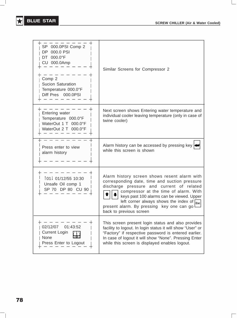
78
SCREW CHILLER (Air & Water Cooled)
Similar Screens for Compressor 2
Next screen shows Entering water temperature andindividual cooler leaving temperature (only in case oftwine cooler)
Alarm history can be accessed by pressing keywhile this screen is shown
Alarm history screen shows resent alarm withcorresponding date, time and suction pressuredischarge pressure and current of related
compressor at the time of alarm. Withkeys past 100 alarms can be viewed. Upperleft corner always shows the index of
present alarm. By pressing key one can goback to previous screen
This screen present login status and also providesfacility to logout. In login status it will show “User” or“Factory” if respective password is entered earlier.In case of logout it will show “None”. Pressing Enterwhile this screen is displayed enables logout.
SP 000.0PSI Comp 2DP 000.0 PSIDT 000.0°FCU 000.0Amp
Comp 2Sucion SaturationTemperature 000.0°FDiff Pres 000.0PSI
Entering waterTemperature 000.0°FWaterOut 1 T 000.0°FWaterOut 2 T 000.0°F
Press enter to viewalarm history
�01� 01/12/55 10:30Unsafe Oil comp 1SP 70 DP 80 CU 90
02/12/07 01:43:52Current LoginNonePress Enter to Logout
�
� �
Esc

79
USER'S MANUAL
Meaning of status display of compressor –
1. Comp1 OFF :- Compressor is selected to be off by the toggle switch
2. Comp1 Ready: - Compressor is selected to be ON by selector switch, all safety delays are over (ifcompressor was tripped earlier), lockout is reset and the compressor ready to get ON. This state is hold for1 minute and then compressor is turned ON depending upon the demand.
a. Comp1 Low Demand: - Compressor is healthy but OFF because of low demand.
b. Comp1 ON:- Compressor is ON with required loading. This is accompanied with the loadingpercentage (25%, 50%, 75% or 100%)
c. Comp1 Loading:- Compressor is loading.
d. Comp1FastUnl:- This state comes at every start of compressor for initial 30 seconds during whichcompressor first to 25% if not during last shutoff.
e. Comp1 Unloading:- Compressor is Unloading due to decreasing demand or proactive unloading.
f. Comp1 Safty Hold:- In the course of proactive unloading when compressor comes out of unloadingcondition and gets ready to load again this state is held for 3 min for confirmation. During this stageloading of compressor as per demand is prohibited.
g. Comp1 Trip: - Compressor is tripped on some safety interlock and the fault condition still persists.
h. Comp1AntiRe:- Compressor has tripped due to some fault or low demand and waiting for anti recycletime. During this state countdown in seconds is also displayed on the display. Compressor isprohibited from starting until countdown timer reaches zero.
i. Comp1 Lockout:- Compressor had one of the serious fault occurred twice in the interval of one hourdue to which compressor is locked out. In this situation compressor will not start even if fault conditionis cleared and anti recycle is over. An operator has to reset the lockout with keypad at User level.After resetting compressor goes in Ready state.
j. Comp1DayLockout:- Compressor had 10 lockouts in the interval of one day (starting from 00:00 atmidnight till next mid night). In this situation compressor is prohibited from starting for that day. Numberof lockouts of each day is reset at mid night. After that an operator can start the compressor.
b) User Level
For going to this level from any screen operator needs to press (Prg) key once & he will reach thenavigation screen
Prg
Status Level
UserFactory Level
This screen shows 3 options out of which middleone is bold and big. On pressing Enter key on thisscreen Operator will be taken to that level whichappears at middle(only after enteringrespective password). With keysdifferent options can be called.
� �

80
SCREW CHILLER (Air & Water Cooled)
This screen is meant for the operator to change thepassword for USER LEVEL.
User Password0000
This is the password entry screen. Operator canget to the value of password with keyswhile pressing key will enter thepassword. If password is wrongmessage will be shown otherwise operator willdirectly go to the next screen of user level.
� �
From this screen operator can enter the set point& differential for each Unit. Again the
values can be changed with keyswhile pressing key will enter the setpoint.
�
� �
�
Leaving Water Temp
Setpoint 045.0°F
Con Zone (-) 01.0°F
Con Zone (+) 02.0°F
This screen allows facility to reset the lockout.Operator need to bring the curser an “N” by
pressing. Then with keys it has tobe made “Y” and then key
should be pressed to reset the lockout.
Reset Lockout for
Comp 1 N
Comp 2 N
New User Password
0000
� �
�
�

81
USER'S MANUAL
c) Status Level
For going to this level from any screen operator needs to press (Prg) key once & he will reach thenavigation screen
Prg
Factory Level
StatusUser Level
� �
Analog Inputs Comp 1
Suction P 000.0PSI
Discharge P 000.0PSI
Discharge T 000.0°F
Status screens show status of analog inputs, Digitalinputs, Digital outputs and the important parametersrelated to the compressor. It doesn’t requires any
password as the screens are only forviewing and modification is not possibleat this level. Using keys one can go
through all of these screens
This screen shows 3 options out of which middleone is bold and big. On pressing Enter key on thisscreen Operator will be taken to that levelwhich appears at middle(only afterentering respective password). With keysdifferent options can be called.
� �Analog Inputs Comp 1
Suct Sat T 000.0°F
Current 000.0Amp
Diff Pres 000.0PSI
Analog Inputs Comp 1
WaterOut T 000.0°F
Dig Inputs Comp 1
Flow Switch Close
SPPR Close
Oil Float sw Close
Dig Outputs Comp 1
Comp main OFF
USV1|USV2|USV3|LQINV
OFF |OFF |OFF |OFF
Comp 1
Lockouts Today 00
Runhours 00000Hrs

82
SCREW CHILLER (Air & Water Cooled)
Similar screens fir compressor 2 if present
Analog Inputs Comp 2
Suction P 000.0 PSI
Discharge P 000.0PSI
Discharge T 000.0°F
Analog Inputs Comp 2
Suct Sat T 000.0°F
Current 000.0Amp
Diff Pres 000.0 PSI
Analog Inputs Comp 2
WaterOut T 000.0°F
Dig Inputs Comp 2
Flow Switch Close
SPPR Close
Oil Float sw Close
Dig Outputs Comp 2
Comp main OFF
USV1|USV2|USV3|LQINV
OFF |OFF |OFF |OFF
Comp 2
Lockouts Today 00
Runhours 00000Hrs
T.O.L. Parameters:-
T.O.L. 00.0
SP Countdown 000
Demand 000
This screen shows important parameters related tothe control algorithm getting executed according tothe trend of load

83
USER'S MANUAL
Last 20 readings of present compressors duringrunning can be accessed from these screens.
Pressing key on particular screen will showreadings of respective compressor
Press enter to view
Current log for
Compressor 1
�01� Comp 1 Data Log
01/11/07 10:32:44
Current 096.0Amp
SP 056.0 DP 120.0
Press enter to view
Current log for
Compressor 2
This is an example of data log screen which showslast reading of current suction discharge pressurealong with date and time stamp. Similar screen can
also show data of compressor 2. Withkeys past 20 logs can be viewed. Upperleft corner always shows the index of
present log. By pressing key one can go backto previous screen.
� �
Esc
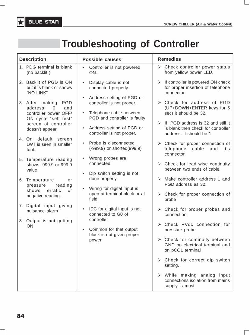
84
SCREW CHILLER (Air & Water Cooled)
Description
1. PDG terminal is blank(no backlit )
2. Backlit of PGD is ONbut it is blank or shows“NO LINK”
3. After making PGDaddress 0 andcontroller power OFF/ON cycle “self test”screen of controllerdoesn’t appear.
4. On default screenLWT is seen in smallerfont.
5. Temperature readingshows -999.9 or 999.9value
6. Temperature orpressure readingshows erratic ornegative reading.
7. Digital input givingnuisance alarm
8. Output is not gettingON
Possible causes
• Controller is not poweredON.
• Display cable is notconnected properly.
• Address setting of PGD orcontroller is not proper.
• Telephone cable betweenPGD and controller is faulty
• Address setting of PGD orcontroller is not proper.
• Probe is disconnected(-999.9) or shorted(999.9)
• Wrong probes areconnected
• Dip switch setting is notdone properly
• Wiring for digital input isopen at terminal block or atfield
• IDC for digital input is notconnected to G0 ofcontroller
• Common for that outputblock is not given properpower
Remedies
� Check controller power statusfrom yellow power LED.
� If controller is powered ON checkfor proper insertion of telephoneconnector.
� Check for address of PGD(UP+DOWN+ENTER keys for 5sec) it should be 32.
� If PGD address is 32 and still itis blank then check for controlleraddress. It should be 1
� Check for proper connection oftelephone cable and it’sconnector.
� Check for lead wise continuitybetween two ends of cable.
� Make controller address 1 andPGD address as 32.
� Check for proper connection ofprobe
� Check for proper probes andconnection.
� Check +Vdc connection forpressure probe
� Check for continuity betweenGND on electrical terminal andon pCO1 terminal
� Check for correct dip switchsetting.
� While making analog inputconnections isolation from mainssupply is must
Troubleshooting of Controller

85
USER'S MANUAL
Shut Down of Compressor
1) Shut down the Chiller by switching off the required switch provided in the Panel.
2) Stop the chilled water supply to the Cooler.
In case of long term shutdown required because of the retrofit of the system or overhaulingof the compressor follow the above instructions after reinstallation of the system beforestarting up again to ensure the safety and good running condition of the compressor
TroubleshootingSr. Problems Problem CauseNo.
1 Sudden trip of motor 1) Low suction pressure or high suction temperaturethermister / Sensor (lack of refrigerant or clogged suction filter) or high
suction superheat.
2) Motor overload. Liquid injection system failure.
3) Motor winding thermister failure.
4) Unstable electrical system or failure.
5) Bad motor coil winding causing the motortemperature to rise rapidly.
2 Compressor Unable 1) Low ambient temperature or High oil viscosity.to load 2) Capillary clogged
3) Modulation solenoid valve clogged or burnt.
4) Internal built in oil lines clogged.- Clean the oil line.
5) Oil filter cartridge clogged. - Clean Oilfilter cartridge.
6) Piston stuck up
3 Compressor unable 1) Modulation solenoid valve clogged or burnt.-to unload repair Solenoid valve.
2) Piston rings worn out or broken, or Cylinderdamaged resulting in leakage.
3) Insufficient lubricant. – Add Lubricant
4) Leakage at discharge cover plate end side.
5) Solenoid valve voltage incorrect.
6) Capacity control logic unsuitable piston stuck-up.
Troubleshooting

86
SCREW CHILLER (Air & Water Cooled)
Sr. Problems Problem CauseNo.
4 Poor insulation value 1) Bad compressor motor coil
of motor 2) Motor power terminal or bolt wet or frosty
3) Motor power terminal or bolt bad or dusty
4) Bad insulation of magnetic contactors
5) Acidified internal refrigeration system
6) Motor coil running for a long time continuouslyunder High Temperature
7) Compressor restart counts too many times
5 Compressor starting 1) Slide valve piston unable to move back to its 25 %failure or star-delta original position.starter shifting failure 2) Voltage incorrect
3) Voltage drop too high when starting thecompressor or magnetic contactor failure.
4) Motor breakdown
5) Phase failure or Phase reversal.
6) Motor thermistor sensor trip.
7) Incorrect power supply connection.
8) Star delta starter timer failure.
9) Discharge stop valve closed.
10) Improper connection between the terminalof star delta wiring.
11) In anti recycling period.
6 High Suction Pressure 1) Cooler water flow rate is higher than the rated
flow rate - Maintain the rated flow rate.
2) Cooler water inlet temperature is higher than rated- Supply the rated temperature cooling water atcooler inlet.
3) System is overcharged - Remove the excessrefrigerant.

87
USER'S MANUAL
MaintenanceMaintenance ScheduleMaintain the Chiller periodically in accordance with the schedules shown in the tables that follow:
Air Cooled Screw Chiller Maintenance Schedule
Check Points Daily Weekly Monthly Quarterly Annually
General
Log parameters X
Check Water Level in expansion tank X
Check up Oil Level X
Check for any refrigerant leaks through Xflare joints, valve glands etc
Check and clean refrigerant strainer X
Check condition of refrigerant drier X
Clean Air cooled condenser coils X
Chemical Cleaning of Condenser Coils X
Clean water line strainers X
Check quality of water X
Check healthy operation of safety devices X
Check tightness of all electrical terminations X
Top up grease for all motors X
Apply thermal paste on the temperature sensors X
Check for any abnormal noise and vibration X
Check liquid line sight glass/moisture indicator X
Check water pressure drop in cooler X
Analyse Oil sample X
Check suction superheat X
Check crank case heater X
Carel Controller
Check program settings X
Check fault history X
Check load/unload furnction X
Check pump down function X
Check fan control function X
Check Clock X

88
SCREW CHILLER (Air & Water Cooled)
MaintenanceMaintenance ScheduleMaintain the Chiller periodically in accordance with the schedules shown in the tables that follow:
Water Cooled Screw Chiller Maintenance Schedule
Check Points Daily Weekly Monthly Quarterly Annually
General
Log parameters X
Check Water Level in expansion tank X
Check Water Level in Cooling Tower X
Check for any refrigerant leaks through Xflare joints, valve glands etc
Check and clean refrigerant strainer X
Check condition of refrigerant drier X
Clean Cooling tower sump X
Clean water line strainers X
Check quality of water X
Check healthy operation of safety devices X
Check tightness of all electrical terminations X
Top up grease for all motors X
Apply thermal paste on the temperature sensors X
Check for any abnormal noise and vibration X
Check liquid line sight glass/moisture indicator X
Check water pressure drop in cooler X
Check water pressure drop in Condenser X
Analyse Oil sample X
Check suction superheat X
Check crank case heater X
Carel Controller
Check program settings X
Check fault history X
Check load/unload furnction X
Check pump down function X
Check Clock X

89
USER'S MANUAL
Maintenance schedule : Compressor
Compressor 1000 2500 5000 10000 15000 20000 25000 30000hrs hrs hrs hrs hrs hrs hrs hrs
Electrical Insulation X X X
Oil filter cartridge X X X
Suction filter X
Capacity control Rpiston rings
Oil level X X X X X X X X
Oil X X X R
Motor thermal X X X X X Xprotector
Bearings X X R
Check Points Time period
X Check or Clean
R Replacement
Note:If acidity of oil measured is lower than PH 6, replace the oil

90
SCREW CHILLER (Air & Water Cooled)
Spare Parts ListSpares for LCAX1-075 D i A / LCAX2-150 D i A
Item Baan Description LCAX1-075 DiA LCAX2-150DiA SpecificationCode Qty Nos. Qty Nos.
Compressor Spares
CDSAI0075 BSC-075A (RC15) Screw Compressor 1 2 VI- 3.0
3101-1143A Oil Filter 1 2 Φ40*200
3101-1146A Inner Gasket of Oil Filter Flange 1 2 Teflon 1.5t
3101-1147A-3 Outer Gasket of Oil Filter Flange 1 2 REINZ-AFM 34, 1.5t
3101-1051B Oil Heater (220V) 1 2 220V, 150W
EASCZ0010 Solenoid Coil for RC comprs. 3 6 220V, SANLAN SMG 1
4401-30 Solenoid Valve (Step Control) 3 6 2743K0R30-4344 SDH12223DS
3101-1003A Solenoid Valve Gasket 3 6 NOK,1515SPS
3103-2104B Oil sight glass (O’ ring included) 1 2 Aluminium
3131-1004A-3 3" Gasket 1 2 REINZ-AFM 34, 1.5t
3103-1024C Suction Filter 1 2 Φ110*103L, 60 Mesh
4405-56 Oil Level Switch 1 2 RFS-8-2, 1200mm
CDSPI0710 Blue Star ACS Oil 16 Litres 32 Litres
Controls & Accessories Spares
RDEAI0060 Sporlan Expansion Valve OVE-70 1 2
EASBI0140 Sporlan SV B10 S2 Solenoid Valve for Liq.Inj. 1 2 15/208 -230/50
EASBI0145 Sporlan SV B10 S2 Solenoid Valve Coil 1 2 MKC - 2
EASBI0170 Sporlan SV B14 S2 Solenoid Valve 1 2for Economiser
EASBI0175 Sporlan SV B14 S2 Solenoid Vavle Coil 1 2
FEDBI0140 CTG Dehydrator (core) 2 4
RDEAI0120 Sporlan Expansion Valve TDEX-11 1 2for Economiser
VAAAZ2010 Valve Angle 1/4 “ 8 12
VAAAZ2106 Sporlan Expansion Valve BBIVE-4 for Liq. Inj. 1 2
EASBZ0040 Pilot Sol. Valve (230V) 1 2 SANLAN 1/4" SAE Flare, /15/240/50 MKC-2 Coil
FAPAZ7020 Bird Wing Fan 4 8 36" Dia. 5 blades
Electrical Spares
FAPAZ7018 Motor for Condenser 4 8 1.2 kW, 2.6 A, 700 RPM, 400 V/3 Ph/ 50 Hz
MBSAZ1900 Oil Cooler Fan Motor Assessmbly 1 - 230 V, 1 Ph, 70 W, 1250 RPM,350 mm Dia. FA/23/3514/K3/F
MBSAZ1800 Oil Cooler Fan Motor Assembly - 1 1 phase, 230 V, 90 W, 1350RPM, 450 mm dia., VBM,FA 23/4514/K5/F

91
USER'S MANUAL
Item Baan Description LCAX1-075 DiA LCAX2-150DiA SpecificationCode Qty Nos. Qty Nos.
EAMAZ0440 Siemens Contactor, 3TF30 10-0A-M0 415 V 2 4 415 V,9 A, 220 VAC Coil, 1 NOfor Condenser fan
EAMAZ0450 Coil for Siemens Contactor, 3TF30,9A, 220 VAC 2 4 AC 50 Hz
EAMAZ0607 SFU Switch 250 Amp. 3 pole, 80KA, DIN Fuse 1 2 Siemens 3KL8321-3UJ00
EAMAZ0608 Fuse link for 250 Amp. SFU 1 2
EATCZ0010 Star Delta Timer Siemens 3RP15 76-1NP30 1 2 24 VAC, 3-60 Seconds, 1 No.Inst. & 1 No. Delayed
EAMAZ0599 Siemens Contactor, 3TF51 02-0A-M0, 415 VAC 2 4 415 V,140 A, 220 VAC Coil,2 NO, 2NC
EAMAZ0600 Coil for Siemens Contactor, 3TF51 02-0A-M0, 2 4 AC 50 Hz220 V AC
EAMAZ0500 Siemens Contactor, 3TF47 72-0A-M0, 220V Coil 1 2 415 V, 70A, 220 VAC Coil, 2NO, 2NC
EAMAZ0510 Coil for Siemens Contactor, 3TF47 72-0A-M0, 1 2 AC 50 Hz220 VAC
EAMAZ0525 SP/PR Minilec Make, VSP D1 1 2 230 V
EASHZ0060 4 Position Selector Switch - Salzer 61198 ON/OFF 1 1 5 A, Rocker Type, SPST
EAMAZ0205 MCB - 4A, 2 Pole, 415V, 10KA, for Controller 1 1 Schneider C60H2P4AC
EAMAZ0316 MCB - 16A, 3 Pole, 415V, 1 0KA, for Fan 2 4 Schneider C60H3P16AC
EAMAZ0530 MCB - 2A, 1 Pole, 415V, 10KA, for Oil Cooler Fan 1 1 Schneider C60H1P2AC
EATDZ0020 Control Transformer, Kavita Make 1 1 0-230V primary 24V secondary,40VA
Micro Control Panel Spares
EATFZ0050 Current Sensor (Samcon) 0 to 300 amps. 1 2 Samcon CT-300
EAMAZ0550 INT 69 module 1 2
EBMCI0002 PCO1000CM0 pCO1 - Medium version, 1 1 24 V AC, I/P, R/O1 MB Flash memory
EBMCI0009 Input expansion board, Carel PCOE00TLN0 - 1
EBMCI0004 PCO1CON0M0 Removable connector kit for pCO1 1 1- Screw version for pCO1 Medium1 MB Flash memory
- PCO100CLK0 pCOC options - Clock card 1 1
EBMCI0003 PGD0000F01 PGD0 terminal for built-in assembly 1 1 LCD, 120x32 pixels, withoutexternal frame
- PGD000FR11 PGD0 terminal for built-in assembly 1 1- Dark grey frame and silverglass for PGD0, neutral
- S90CONN000 Telephone-type connection cable,1.5 m long, with telephone connectors 1 1
EBMCI0100 NTC015WP00 WP type NTC probes 4 6 IP68, 1.5m cable, -50T105°C
EBMCI0080 SPKT00B1C0 Pr Transducer 2 4 0-44.8bar
EBMCI0090 SPKC002300 Cable 2m for pr sensor 2 4

92
SCREW CHILLER (Air & Water Cooled)
Spares for LCWX1-115 D i B / LCWX2-225 D i BItem Baan Description LCWX1-115DiB LCWX2-225DiB SpecificationCode Qty Nos. Qty Nos.
Compressor Spares
CDSAI0080 BSC-105A (RC16) Screw Compressor 1 2 VI 3.0for R 22
3105-1143A Oil Filter 1 2 Φ56*200
3105-1146A Inner Gasket of Oil Filter Flange 1 2 Teflon 1.5t
3101-1148A-3 Outer Gasket of Oil Filter Flange 1 2 REINZ-AFM 34, 1.5t
3101-1051B Oil Heater (220V) 1 2 220V, 150W
EASCZ0010 Solenoid Coil for RC comprs. 3 6 220V, SANLAN SMG 1
4401-30 Solenoid Valve 3 6 2743K0R30-4344 SDH12223DS
3101-1003A Solenoid Valve Gasket 3 6 NOK,1515SPS
4804-01 Oil Sight Glass (O-Ring Included) 1 2 ALCO
3105-1024C Suction Filter 1 2 Φ110*103L
3105-1004A-3 Gasket for 4" Flange 1 2 REINZ-AFM 34, 1.5t
4405-56 Oil Level Switch 1 2 RFS-8-2, 1200mm
CDSPI0710 Blue Star ACS Oil 18 Liters 36 Liters
Controls & Accessories spares
RDEAI0070 Sporlan Expansion Valve VVE-100 1 2
EASBI0170 Sporlan SV B14 S2 Solenoid Valve - -for Economiser
EASBI0175 Sporlan SV B14 S2 Solenoid Valve - -for Economiser Coil
EASBI0140 Sporlan SV B10 S2 Solenoid Valve for Liq. Inj. 1 2
EASBI0145 Sporlan SV B10 S2 Solenoid Valve Coil 1 2for Liquid injection
RDEAI0120 Danfoss Expansion Valve TDEX-11 - -for Economiser
FEDBI0140 CTG Dehydrator (Core) (L Type Strainer) 3 6
SAMAI0010 Indicator Moisture 1 2 1-5/8"
EASBZ0040 Pilot Sol. Valve (230V) 1 2 SANLAN 1/4" SAE Flare,15/240/50 MKC-2 Coil
VAAAZ7090 Danfoss Expansion Valve TDEX-7.5 1 2for Liquid Injection
VAAAZ2010 Valve Angle 1/4 “ 8 12
Electrical spares
EATCZ0010 Star Delta Timer Siemens 3RP15 76-1NP30 1 2 24 VAC, 3-60 Seconds,1 NO Inst. & 1 NO Delayed
EAMAZ0594 SFU switch 200 Amp, 3 pole, 80KA 1 2 Siemens 3KL8311-3UJ00
EAMAZ0596 Fuse Link for 200 Amp SFU 1 2
EAMAZ0591 Siemens Contactor, 3TF50 02-0A-M0, 415 VAC 2 4 415 V,110 A, 220 VAC Coil,2 NO, 2NC
EAMAZ0598 Coil for Contactor, 3TF50, 110A ,220 V 2 4 AC 50 Hz

93
USER'S MANUAL
Item Baan Description LCWX1-115DiB LCWX2-225DiB SpecificationCode Qty Nos. Qty Nos.
EAMAZ0500 Siemens Contactor, 3TF47 72-0A-M0, 1 2 415 V,70 A, 220 VAC Coil,220 VAC Coil 2 NO, 2NC
EAMAZ0510 Coil for Siemens Contactor, 3TF47 72-0A-M0, 1 2 AC 50 Hz220 VAC
EAMAZ0525 SP/PR Minilec Make, VSP D1 1 2 230 V
EASHZ0060 4 Positionn Selector Switch-Salzer 61198 ON/OFF 1 1 5 A, Rocker Type, SPST
EAMAZ0205 MCB - 4A, 2 Pole, 415V, 10KA, for Controller 1 1 Schneider C60H2P4AC
EATDZ0020 Control Transformer, Kavita Make 1 1 0-230V primary24V secondary, 40VA
Micro Control Panel spares
EATFZ0050 Current Sensor (Samcon) 0 to 300 amps. 1 2 Samcon CT-300
EAMAZ0550 INT 69 module 1 2
EBMCI0002 PCO1000CM0 pCO1 - Medium version, 1 1 24 V AC, I/P, R/O1 MB Flash memory
EBMCI0009 Input expansion board, Carel PCOE00TLN0 - 1
EBMCI0004 PCO1CON0M0 Removable connector kit for pCO1 1 1- Screw version for pCO1 Medium
- PCO100CLK0 pCOC options - Clock card 1 1
EBMCI0003 PGD0000F01 PGD0 terminal for built-in assembly 1 1 LCD, 120x32 pixels, withoutexternal frame
- PGD000FR11 PGD0 terminal for built-in assembly 1 1- Dark grey frame and silver glassfor PGD0, neutral
- S90CONN000 Telephone-type connection cable, 1 11.5 m long, with telephone connectors
EBMCI0100 NTC015WP00 WP type NTC probes 3 4 IP68, 1.5 m cable, -50T105 °C
EBMCI0080 SPKT00B1C0 Pr Transducer 2 4 0-44.8bar
EBMCI0090 SPKC002300 Cable 2m for pr sensor 2 4

94
SCREW CHILLER (Air & Water Cooled)
Spares for LCAX1-102 D i A / LCAX2-204 D i AItem Baan Description LCAX1-102DiA LCAX2-204DiA SpecificationCode Qty Nos. Qty Nos.
Compressor Spares
CDSAI0080 BSC-105A (RC16) Screw Compressor 1 2 VI 3.0for R 22
3105-1143A Oil Filter 1 2 Φ56*200
3105-1146A Inner Gasket of Oil Filter Flange 1 2 Teflon 1.5t
3101-1148A-3 Outer Gasket of Oil Filter Flange 1 2 REINZ-AFM 34, 1.5t
3101-1051B Oil Heater (220V) 1 2 220V, 150W
EASCZ0010 Solenoid Coil for RC comprs. 3 6 220V, SANLAN SMG 1
4401-30 Solenoid Valve 3 6 2743K0R30-4344 SDH12223DS
3101-1003A Solenoid Valve Gasket 3 6 NOK,1515SPS
4804-01 Oil Sight Glass (O-Ring Included) 1 2 ALCO
3105-1024C Suction Filter 1 2 Φ110*103L
3105-1004A-3 Gasket for 4" Flange 1 2 REINZ-AFM 34, 1.5t
4405-56 Oil Level Switch 1 2 RFS-8-2, 1200mm
CDSPI0710 Blue Star ACS Oil 18 Liters 36 Liters
Controls & Accessories spares
RDEAI0070 Sporlan Expansion Valve VVE-100 1 2
EASBI0170 Sporlan SV B14 S2 Solenoid Valve 1 2for Economiser
EASBI0175 Sporlan SV B14 S2 Solenoid Valve 1 2for Economiser Coil
EASBI0140 Sporlan SV B10 S2 Solenoid Valve for Liq. Inj. 1 2
EASBI0145 Sporlan SV B10 S2 Solenoid Valve Coil 1 2for Liquid injection
RDEAI0120 Danfoss Expansion Valve TDEX-11 1 2for Economiser
FEDBI0140 CTG Dehydrator (Core) (L Type Strainer) 3 6
SAMAI0010 Indicator Moisture 1 2 1-5/8"
EASBZ0040 Pilot Sol. Valve (230V) 1 2 SANLAN 1/4" SAE Flare,15/240/50 MKC-2 Coil
VAAAZ7090 Danfoss Expansion Valve TDEX-7.5 1 2for Liquid Injection
VAAAZ2010 Valve Angle 1/4 “ 8 12
FAPAZ7020 Bird Wing Fan 6 12 36" Dia. 5 blades
Electrical spares
FAPAZ7018 Motor for condenser 6 12 1.2 KW, 2.6 A, 700 RPM,400V/ 3Ph/ 50 Hz
MBSAZ1800 Oil Cooler Fan Motor Assembly 1 2 1 Ph, 230 V, 90 W, 1350 RPM,450 mm dia., VBM,FA 23/4514/K5/F
EAMAZ0440 Siemens Contactor, 3TF31 10-0A-M0 415VAC 2 4 415 V,12 A, 220 VAC Coil,1 NO

95
USER'S MANUAL
Item Baan Description LCAX1-102DiA LCAX2-204DiA SpecificationCode Qty Nos. Qty Nos.
EAMAZ0450 Coil for Siemens Contactor, 3TF31,12A, 220 VAC 2 4 AC 50 Hz
EATCZ0010 Star Delta Timer Siemens 3RP15 76-1NP30 1 2 24 VAC, 3-60 Seconds,1 NO Inst. & 1 NO Delayed
EAMAZ0594 SFU switch 315 Amp, 3 pole, 80KA 1 2 Siemens 3KL8331-3UJ00
EAMAZ0596 Fuse Link for 315 Amp SFU 1 2
EAMAZ0599 Siemens Contactor, 3TF51 02-0A-M0 415 VAC 2 4 415 V,140 A, 220 VAC Coil,2 NO, 2NC
EAMAZ0600 Coil for Contactor, 3TF51,140A 2 4 AC 50 Hz
EAMAZ0591 Siemens Contactor, 3TF50 02-0A-M0, 415 VAC 1 2 415 V,110 A, 220 VAC Coil,2 NO, 2NC
EAMAZ0598 Coil for Contactor, 3TF50, 110A ,220 V 1 2 AC 50 Hz
EAMAZ0525 SP/PR Minilec Make, VSP D1 1 2 230 V
EASHZ0060 4 Position Selector Switch-Salzer 61198 ON/OFF 1 1 5 A, Rocker Type, SPST
EAMAZ0205 MCB - 4A, 2 Pole, 415V, 10KA, for Controller 1 1 Schneider C60H2P4AC
EAMAZ0316 MCB - 16A, 3 Pole, 415V, 10KA, for Fan 2 4 Schneider C60H3P16AC
EAMAZ0316 MCB - 2A, 1 Pole, 415V, 10KA, 1 2 Schneider C60H1P2Afor Oil Cooler Fan
EATDZ0020 Control Transformer, Kavita Make 1 1 0-230V primary24V secondary, 40VA
Micro Control Panel spares
EATFZ0050 Current Sensor (Samcon) 0 to 300 amps. 1 2 Samcon CT-300
EAMAZ0550 INT 69 module 1 2
EBMCI0002 PCO1000CM0 pCO1 - Medium version, 1 1 24 V AC, I/P, R/O1 MB Flash memory
EBMCI0009 Input expansion board, Carel PCOE00TLN0 - 1
EBMCI0004 PCO1CON0M0 Removable connector kit for pCO1 1 1- Screw version for pCO1 Medium
- PCO100CLK0 pCOC options - Clock card 1 1
EBMCI0003 PGD0000F01 PGD0 terminal for built-in assembly 1 1 LCD, 120x32 pixels, withoutexternal frame
- PGD000FR11 PGD0 terminal for built-in assembly 1 1- Dark grey frame and silver glassfor PGD0, neutral
- S90CONN000 Telephone-type connection cable, 1 11.5 m long, with telephone connectors
EBMCI0100 NTC015WP00 WP type NTC probes 4 6 IP68, 1.5 m cable, -50T105 °C
EBMCI0080 SPKT00B1C0 Pr Transducer 2 4 0-44.8bar
EBMCI0090 SPKC002300 Cable 2m for pr sensor 2 4

96
SCREW CHILLER (Air & Water Cooled)
Spares for LCWX1-135 D i BItem BaaN Description LCWX1-135DiB SpecificationCode QTY, Nos.
Compressor Spares
CDSAI0080 BSC-130W (RC17) Screw 1 VI 3.0Compressor for R 22
3105-1143A Oil Filter 1 Φ56*200
3105-1146A Inner Gasket of Oil Filter Flange 1 Teflon 1.5t
3101-1148A-3 Outer Gasket of Oil Filter Flange 1 REINZ-AFM 34, 1.5t
3101-1051B Oil Heater (220V) 1 220V, 150W
EASCZ0010 Solenoid Coil for RC comprs. 3 220V, SANLAN SMG 1
4401-30 Solenoid Valve 3 2743K0R30-4344 SDH12223DS
3101-1003A Solenoid Valve Gasket 3 NOK,1515SPS
4804-01 Oil Sight Glass (O-Ring Included) 1 ALCO
3105-1024C Suction Filter 1 Φ110*103L
3105-1004A-3 Gasket for 4" Flange 1 REINZ-AFM 34, 1.5t
4405-56 Oil Level Switch 1 RFS-8-2, 1200mm
CDSPI0710 Blue Star ACS Oil 18 Liters
Controls & Accessories spares
RDEAI0070 Sporlan Expansion Valve VVE-100 1
EASBI0140 Sporlan SV B10 S2 Solenoid Valve 1for Liquid Injection
EASBI0145 Sporlan SV B10 S2 Solenoid Valve 1Coil for Liquid Injection
FEDBI0140 CTG Dehydrator (Core) (L Type Strainer) 3
SAMAI0010 Indicator Moisture 1 1-5/8"
EASBZ0040 Pilot Sol. Valve (230V) 1 SANLAN 1/4" SAE Flare, 15/240/50MKC-2 Coil
VAAAZ7090 Danfoss Expansion Valve TDEX-7.5 1for Liquid Injection
VAAAZ2010 Valve Angle 1/4 “ 8
Electrical spares
EATCZ0010 Star Delta Timer Siemens 1 24 VAC, 3-60 Seconds,3RP15 76-1NP30 1 NO. Inst. & 1 NO Delayed
- SFU switch 200 Amp, 3 pole, 80KA 1 Siemens 3KL8311-3UJ00
- Fuse Link for 200 Amp SFU 1
EAMAZ0591 Siemens Contactor, 3TF50 02-0A-M0, 2 415 V,110 A, 220 VAC Coil,415 VAC 2 NO, 2NC

97
USER'S MANUAL
Item BaaN Description LCWX1-135DiB SpecificationCode QTY, Nos.
EAMAZ0598 Coil for Contactor, 3TF50, 110A ,220 V 2 AC 50 Hz
EAMAZ0500 Siemens Contactor, 3TF47 72-0A-M0, 1 415 V,70A, 220 VAC Coil,220 VAC Coil 2 NO, 2NC
EAMAZ0510 Coil for Siemens Contactor, 3TF47 1 AC 50 Hz72-0A-M0, 220 VAC
EAMAZ0525 SP/PR Minilec Make, VSP D1 1 230 V
EASHZ0060 4 Positionn Selector Switch 1 5 A, Rocker Type, SPST- Salzer 61198 ON/OFF
EAMAZ0205 MCB - 4A, 2 Pole, 415V, 10KA, for Controller 1 Schneider C60H2P4AC
EATDZ0020 Control Transformer, Kavita Make 1 0-230V primary 24V secondary,40VA
Micro Control Panel spares
EATFZ0050 Current Sensor (Samcon) 0 to 300 amps. 1 Samcon CT-300
EAMAZ0550 INT 69 module 1
EBMCI0002 PCO1000CM0 pCO1 - Medium version, 1 24 VAC, I/P, R/O1 MB Flash memory
EBMCI0004 PCO1CON0M0 Removable connector kit 1for pCO1 - Screw version for pCO1 Medium
- PCO100CLK0 pCOC options - Clock card 1
EBMCI0003 PGD0000F01 PGD0 terminal for built-in 1 LCD, 120x32 pixels, withoutassembly external frame
- PGD000FR11 PGD0 terminal for built-in 1assembly - Dark grey frame and silverglass for PGD0, neutral
- S90CONN000 Telephone-type connection 1cable, 1.5 m long, withtelephone connectors
EBMCI0100 NTC015WP00 WP type NTC probes 3 IP68, 1.5 m cable, -50T105 °C
EBMCI0080 SPKT00B1C0 Pr Transducer 2 0-44.8bar
EBMCI0090 SPKC002300 Cable 2m for pr sensor 2

98
SCREW CHILLER (Air & Water Cooled)
Spares for LCWX1-160 D i B / LCWX2-315 D i BItem Baan Description LCWX1-160DiB LCWX2-315DiB SpecificationCode Qty Nos. Qty Nos.
Compressor spares
CDSAI0090 BSC-145A (RC18) Screw Compressor 1 2 Vi - 3.0
3105-1143A Oil Filter 1 2
3105-1146A Inner Gasket of Oil Filter Flange 1 2 Teflon 1.5t
3101-1051B Oil Heater (220V) 1 2 220V,150W
3101-1006A-3 Gasket (For Motor Cable Cover Plate) 1 2 REINZ-AFM 34, 1.5t
EASCZ0010 Solenoid Coil for RC comprs. 3 6 220V, SANLAN SMG 1
4401-30 Solenoid Valve 3 6 2743K0R30-4344 SDH12223DS
3101-1003A Solenoid Valve Gasket 3 6 NOK,1515SPS
4804-01 Oil Sight Glass (O-Ring included) 1 2 ALCO
3105-1004A-3 Gasket for 4" Flange 1 2 REINZ-AFM 34, 1.5t
4405-56 Oil Level Switch 1 2 RFS-8-2, 1200mm
CDSPI0710 Blue Star ACS Oil 18 liters 36 liters
Controls and Accessories Spares
RDEAI0060 Sporlan Expansion Valve OVE-70 2 4
EASBI0140 Sporlan SV B10 S2 Solenoid Valve for Liq. Inj. 1 2
EASBI0145 Sporlan SV B10 S2 Solenoid Valve Coil 1 2
FEDBI0140 CTG Dehydrator (Core) 3 6
EASBZ0040 Pilot Sol. Valve (230V) 1 2 SANLAN 1/4" SAE Flare,15/240/50 MKC-2 Coil
VAAAZ7090 Danfoss Expansion Valve TDEX-7.5 for Liq. Inj. 1 2
VAAAZ2010 Valve Angle 1/4 “ 8 16
Electrical Spares
EATCZ0010 Star Delta Timer Siemens 3RP15 76-1NP30 1 2 24 VAC, 3-60 Seconds,1 NO Inst. & 1 NO Delayed
EAMAZ0607 SFU Switch 250 Amp. 3 pole, 80KA 1 2 Siemens 3KL8321-3UJ00
EAMAZ0608 Fuse link for 250 Amp. SFU 1 2
EAMAZ0603 Siemens Contactor 3TF53 02-0A-M0, 415 VAC - - 415 V,205 A, 220 VAC Coil,2NO, 2 NC
EAMAZ0599 Siemens Contactor, 3TF51 02-0A-M0, 415 VAC 2 4 415 V,140 A, 220 VAC Coil,2 NO, 2NC
EAMAZ0600 Coil for Siemens Contactor, 3TF51 02-0A-M0, 2 4 AC 50 Hz220 VAC
EAMAZ0599 Siemens Contactor, 3TF49 22-0A-P0, 415 VAC 1 2 415 V,85 A, 220 VAC Coil,2 NO, 2NC
EAMAZ0600 Coil for Siemens Contactor, 3TF49 22-0A-P0, 1 2 AC 50 Hz220 VAC

99
USER'S MANUAL
Item Baan Description LCWX1-160DiB LCWX2-315DiB SpecificationCode Qty Nos. Qty Nos.
EAMAZ0525 SP/PR Minilec Make, VSP D1 1 2 230 V
EASHZ0060 4 Position Selector Switch-Salzer 61198 ON/OFF 1 1 5 A, Rocker Type, SPST
EAMAZ0205 MCB - 4A, 2 Pole, 415V, 10KA, for Controller 1 1 Schneider C60H2P4AC
EATDZ0020 Control Transformer, Kavita Make 1 1 0-230V primary 24Vsecondary, 40VA
Micro Control Panel Spares
EATFZ0050 Current Sensor (Samcon) 0 to 300 Amps. 1 2 Samcon CT-300
EAMAZ0550 INT 69 module 1 2
EBMCI0002 PCO1000CM0 pCO1 - Medium version, 1 1 24 V AC, I/P, R/O1 MB Flash memory
EBMCI0009 Input expansion board, Carel PCOE00TLN0 - 1
EBMCI0004 PCO1CON0M0 Removable connector kit for pCO1 1 1- Screw version for pCO1 Medium
- PCO100CLK0 pCOC options - Clock card 1 1
EBMCI0003 PGD0000F01 PGD0 terminal for built-in assembly 1 1 LCD, 120x32 pixels, withoutexternal frame
- PGD000FR11 PGD0 terminal for built-in assembly 1 1- Dark grey frame and silver glassfor PGD0, neutral
- S90CONN000 Telephone-type connection cable, 1 11.5 m long, with telephone connectors
EBMCI0100 NTC015WP00 WP type NTC probes 3 6 IP68, 1.5 m cable, -50T105 °C
EBMCI0080 SPKT00B1C0 Pr Transducer 2 4 0-44.8bar
EBMCI0090 SPKC002300 Cable 2m for pr sensor 2 4
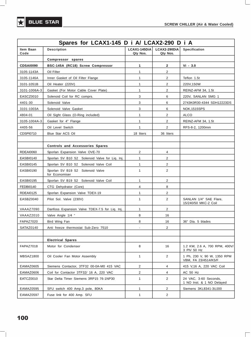
100
SCREW CHILLER (Air & Water Cooled)
Spares for LCAX1-145 D i A/ LCAX2-290 D i AItem Baan Description LCAX1-145DiA LCAX2-290DiA SpecificationCode Qty Nos. Qty Nos.
Compressor spares
CDSAI0090 BSC-145A (RC18) Screw Compressor 1 2 Vi - 3.0
3105-1143A Oil Filter 1 2
3105-1146A Inner Gasket of Oil Filter Flange 1 2 Teflon 1.5t
3101-1051B Oil Heater (220V) 1 2 220V,150W
3101-1006A-3 Gasket (For Motor Cable Cover Plate) 1 2 REINZ-AFM 34, 1.5t
EASCZ0010 Solenoid Coil for RC comprs. 3 6 220V, SANLAN SMG 1
4401-30 Solenoid Valve 3 6 2743K0R30-4344 SDH12223DS
3101-1003A Solenoid Valve Gasket 3 6 NOK,1515SPS
4804-01 Oil Sight Glass (O-Ring included) 1 2 ALCO
3105-1004A-3 Gasket for 4" Flange 1 2 REINZ-AFM 34, 1.5t
4405-56 Oil Level Switch 1 2 RFS-8-2, 1200mm
CDSPI0710 Blue Star ACS Oil 18 liters 36 liters
Controls and Accessories Spares
RDEAI0060 Sporlan Expansion Valve OVE-70 2 4
EASBI0140 Sporlan SV B10 S2 Solenoid Valve for Liq. Inj. 1 2
EASBI0145 Sporlan SV B10 S2 Solenoid Valve Coil 1 2
EASBI0190 Sporlan SV B19 S2 Solenoid Valve 1 2for Economiser
EASBI0195 Sporlan SV B19 S2 Solenoid Valve Coil 1 2
FEDBI0140 CTG Dehydrator (Core) 4 8
RDEAI0125 Sporlan Expansion Valve TDEX-19 1 2
EASBZ0040 Pilot Sol. Valve (230V) 1 2 SANLAN 1/4" SAE Flare,15/240/50 MKC-2 Coil
VAAAZ7090 Danfoss Expansion Valve TDEX-7.5 for Liq. Inj. 1 2
VAAAZ2010 Valve Angle 1/4 “ 8 16
FAPAZ7020 Bird Wing Fan 8 16 36" Dia. 5 blades
SATAZ0140 Anti freeze thermostat Sub-Zero 7510 - 2
Electrical Spares
FAPAZ7018 Motor for Condenser 8 16 1.2 KW, 2.6 A, 700 RPM, 400V/3 Ph/ 50 Hz
MBSAZ1800 Oil Cooler Fan Motor Assembly 1 2 1 Ph, 230 V, 90 W, 1350 RPMVBM, FA 23/4514/K5/F
EAMAZ0605 Siemens Contactor, 3TF32 00-0A-M0 415 VAC 2 4 415 V,16 A, 220 VAC Coil
EAMAZ0606 Coil for Contactor 3TF32/ 16 A, 220 VAC 2 4 AC 50 Hz
EATCZ0010 Star Delta Timer Siemens 3RP15 76-1NP30 1 2 24 VAC, 3-60 Seconds,1 NO Inst. & 1 NO Delayed
EAMAZ0595 SFU switch 400 Amp.3 pole, 80KA 1 2 Siemens 3KL8341-3UJ00
EAMAZ0597 Fuse link for 400 Amp. SFU 1 2

101
USER'S MANUAL
Item Baan Description LCAX1-145DiA LCAX2-290DiA SpecificationCode Qty Nos. Qty Nos.
EAMAZ0603 Siemens Contactor 3TF53 02-0A-M0, 415 VAC 2 4 415 V,205 A, 220 VAC Coil,2 NO, 2 NC
EAMAZ0604 Coil for Contactor, 3TF53/205A, 220 V 2 4 AC 50 Hz
EAMAZ0591 Siemens Contactor, 3TF50 02-0A-M0, 415 VAC 1 2 415 V, 110 A, 220 VAC Coil,2 NO, 2 NC
EAMAZ0598 Coil for Contactor, 3TF50, 110A ,220 V 1 2 AC 50 Hz
EAMAZ0525 SP/PR Minilec Make, VSP D1 1 2 230 V
EASHZ0060 4 Position Selector Switch-Salzer 61198 ON/OFF 1 1 5 A, Rocker Type, SPST
EAMAZ0205 MCB - 4A, 2 Pole, 415V, 10KA, for Controller 1 1 Schneider C60H2P4AC
EAMAZ0316 MCB - 16A, 3 Pole, 415V, 10KA, for Fan 2 4 Schneider C60H3P16AC
EAMAZ0316 MCB - 2A, 1 Pole, 415V, 10KA, 1 2 Schneider C60H1P2ACfor Oil Cooler Fan
EATDZ0020 Control Transformer, Kavita Make 1 1 0-230V primary 24Vsecondary, 40VA
Micro Control Panel Spares
EATFZ0050 Current Sensor (Samcon) 0 to 300 Amps. 1 2 Samcon CT-300
EAMAZ0550 INT 69 module 1 2
EBMCI0002 PCO1000CM0 pCO1 - Medium version, 1 1 24 V AC, I/P, R/O1 MB Flash memory
EBMCI0009 Input expansion board, Carel PCOE00TLN0 - 1
EBMCI0004 PCO1CON0M0 Removable connector kit for pCO1 1 1- Screw version for pCO1 Medium
- PCO100CLK0 pCOC options - Clock card 1 1
EBMCI0003 PGD0000F01 PGD0 terminal for built-in assembly 1 1 LCD, 120x32 pixels, withoutexternal frame
- PGD000FR11 PGD0 terminal for built-in assembly 1 1- Dark grey frame and silver glassfor PGD0, neutral
- S90CONN000 Telephone-type connection cable, 1 11.5 m long, with telephone connectors
EBMCI0100 NTC015WP00 WP type NTC probes 4 6 IP68, 1.5 m cable, -50T105 °C
EBMCI0080 SPKT00B1C0 Pr Transducer 2 4 0-44.8bar
EBMCI0090 SPKC002300 Cable 2m for pr sensor 2 4

102
SCREW CHILLER (Air & Water Cooled)
Spares for LCAX2-177 D i AItem BaaN Description LCAX2-177 D i A SpecificationCode QTY, Nos.
Compressor Spares
CDSAI0080 BSC-105A (RC16) Screw Compressor 1 VI- 3.0for R 22
3105-1143A Oil Filter 1 Φ56*200
3105-1146A Inner Gasket of Oil Filter Flange 1 Teflon 1.5t
3101-1148A-3 Outer Gasket of Oil Filter Flange 1 REINZ-AFM 34, 1.5t
3101-1051B Oil Heater (220V) 1 220V, 150W
EASCZ0010 Solenoid Coil for RC comprs. 3 220V, SANLAN SMG 1
4401-30 Solenoid Valve 3 2743K0R30-4344 SDH12223DS
3101-1003A Solenoid Valve Gasket 3 NOK,1515SPS
4804-01 Oil Sight Glass (O-Ring Included) 1 ALCO
3105-1024C Suction Filter 1 Φ110*103L
3105-1004A-3 Gasket for 4" Flange 1 REINZ-AFM 34, 1.5t
4405-56 Oil Level Switch 1 RFS-8-2, 1200mm
CDSPI0710 Blue Star ACS Oil 18 Liters
CDSAI0075 BSC-075A (RC15) Screw Compressor 1 VI- 3.0
3101-1143A Oil Filter 1 Φ40*200
3101-1146A Inner Gasket of Oil Filter Flange 1 Teflon 1.5t
3101-1147A-3 Outer Gasket of Oil Filter Flange 1 REINZ-AFM 34, 1.5t
3101-1051B Oil Heater (220V) 1 220V, 150W
EASCZ0010 Solenoid Coil for RC comprs. 3 220V, SANLAN SMG 1
4401-30 Solenoid Valve (Step Control) 3 2743K0R30-4344 SDH12223DS
3101-1003A Solenoid Valve Gasket 3 NOK,1515SPS
3103-2104B Oil sight glass (O’ ring included) 1 Aluminium
3131-1004A-3 3" Gasket 1 REINZ-AFM 34, 1.5t
3103-1024C Suction Filter 1 Φ110*103L, 60 Mesh
4405-56 Oil Level Switch 1 RFS-8-2, 1200mm
CDSPI0710 Blue Star ACS Oil 16 Litres
Controls and Accessories Spares
RDEAI0060 Sporlan Expansion Valve OVE-70 1
RDEAI0070 Sporlan Expansion Valve VVE-100 1
EASBI0140 Sporlan SV B10 S2 Solenoid Valvefor Liquid Injection 2
EASBI0145 Sporlan SV B10 S2 Solenoid Valve Coil 2
EASBI0170 Sporlan SV B14 S2 Solenoid Valvefor Economiser 2
EASBI0175 Sporlan SV B14 S2 Solenoid Vavle Coil 2
FEDBI0140 CTG Dehydrator (core) 5
RDEAI0120 Danfoss Expansion Valve TDEX-11 2for Economiser
VAAAZ2010 Valve Angle 1/4“ 16
VAAAZ2106 Sporlan Expansion Valve BBIVE-4 1for Liquid Injection
VAAAZ7090 Danfoss Expansion Valve TDEX-7.5 1for Liquid Injection
EASBZ0040 Pilot Sol. Valve (230V) 2 SANLAN 1/4" SAE Flare, 15/240/50MKC-2 Coil
FAPAZ7020 Bird Wing Fan 12 36" Dia. 5 blades
Electrical Spares
FAPAZ7018 Motor for Condenser 12 1.2 KW, 2.6 A, 700 RPM, 400 V/3 Ph/ 50 Hz
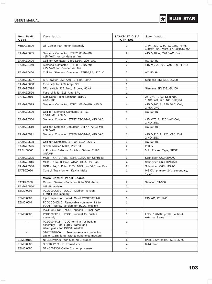
103
USER'S MANUAL
Item BaaN Description LCAX2-177 D i A SpecificationCode QTY, Nos.
MBSAZ1800 Oil Cooler Fan Motor Assembly 2 1 Ph. 230 V, 90 W, 1350 RPM,450mm dia., VBM, FA 23/4514/K5/F
EAMAZ0605 Siemens Contactor, 3TF32 00-0A-M0 2 415 V,16 A, 220 VAC Coil415 VAC for condenser fan
EAMAZ0606 Coil for Contactor 3TF32,16A, 220 VAC 2 AC 50 Hz
EAMAZ0440 Siemens Contactor, 3TF30 10-0A-M0 2 415 V,9 A, 220 VAC Coil, 1 NO415 VAC for Condenser fan
EAMAZ0450 Coil for Siemens Contactor, 3TF30,9A, 220 V 2 AC 50 Hz
EAMAZ0607 SFU Switch 250 Amp. 3 pole, 80KA 1 Siemens 3KL8321-3UJ00
EAMAZ0608 Fuse link for 250 Amp. SFU 1
EAMAZ0594 SFU switch 315 Amp, 3 pole, 80KA 1 Siemens 3KL8331-3UJ00
EAMAZ0596 Fuse Link for 315 Amp SFU 1
EATCZ0010 Star Delta Timer Siemens 3RP15 2 24 VAC, 3-60 Seconds,76-1NP30 1 NO Inst. & 1 NO Delayed
EAMAZ0599 Siemens Contactor, 3TF51 02-0A-M0, 415 V 4 415 V,140 A, 220 VAC Coil,2 NO, 2NC
EAMAZ0600 Coil for Siemens Contactor, 3TF51 4 AC 50 Hz02-0A-M0, 220 V
EAMAZ0500 Siemens Contactor, 3TF47 72-0A-M0, 415 VAC 1 415 V,70 A, 220 VAC Coil,2 NO, 2NC
EAMAZ0510 Coil for Siemens Contactor, 3TF47 72-0A-M0, 1 AC 50 Hz220 VAC
EAMAZ0591 Siemens Contactor, 3TF50 02-0A-M0, 415 VAC 1 415 V,110 A, 220 VAC Coil,2 NO, 2NC
EAMAZ0598 Coil for Contactor, 3TF50, 110A ,220 V 1 AC 50 Hz
EAMAZ0525 SP/PR Minilec Make, VSP D1 2 230 V
EASHZ0060 4 Position Selector Switch - Salzer 61198 1 5 A, Rocker Type, SPSTON/OFF
EAMAZ0205 MCB - 4A, 2 Pole, 415V, 10KA, for Controller 1 Schneider C60H2P4AC
EAMAZ0316 MCB - 16A, 3 Pole, 415V, 10KA, for Fan 4 Schneider C60H3P16AC
EAMAZ0530 MCB - 2A, 1 Pole, 415V, 10KA, for Oil Cooler Fan 2 Schneider C60H1P2AC
EATDZ0020 Control Transformer, Kavita Make 1 0-230V primary 24V secondary,40VA
Micro Control Panel Spares
EATFZ0050 Current Sensor (Samcon) 0 to 300 Amps. 2 Samcon CT-300
EAMAZ0550 INT 69 module 2
EBMCI0002 PCO1000CM0 pCO1 - Medium version, 11 MB Flash memory
EBMCI0009 Input expansion board, Carel PCOE00TLN0 1 24V AC, I/P, R/O
EBMCI0004 PCO1CON0M0 Removable connector kit for 1pCO1 - Screw version for pCO1 Medium
- PCO100CLK0 pCOC options - Clock card 1
EBMCI0003 PGD0000F01 PGD0 terminal for built-in 1 LCD, 120x32 pixels, withoutassembly external frame
- PGD000FR11 PGD0 terminal for built-in 1assembly - Dark grey frame andsilver glass for PGD0, neutral
- S90CONN000 Telephone-type connection 1cable, 1.5m long, with telephone connectors
EBMCI0100 NTC015WP00 WP type NTC probes 6 IP68, 1.5m cable, -50T105 °C
EBMCI0080 SPKT00B1C0 Pr Transducer 4 0-44.8bar
EBMCI0090 SPKC002300 Cable 2m for pr sensor 4

104
SCREW CHILLER (Air & Water Cooled)
Spares for LCWX2-270 D i B, LCAX2-247 D i AItem Baan Description LCWX2-270DiB LCAX2-247DiA SpecificationCode Qty Nos. Qty Nos.
Compressor Spares
CDSAI0080 BSC-105A (RC16) Screw Compressor 1 1 Vi - 3.0for R 22
3105-1143A Oil Filter 1 1 Φ56*200
3105-1146A Inner Gasket of Oil Filter Flange 1 1 Teflon 1.5t
3101-1148A-3 Outer Gasket of Oil Filter Flange 1 1 REINZ-AFM 34, 1.5t
3101-1051B Oil Heater (220V) 1 1 220V, 150W
EASCZ0010 Solenoid Coil for RC comprs. 3 3 220V, SANLAN SMG 1
4401-30 Solenoid Valve 3 3 2743K0R30-4344 SDH12223DS
3101-1003A Solenoid Valve Gasket 3 3 NOK,1515SPS
4804-01 Oil Sight Glass (O-Ring Included) 1 1 ALCO
3105-1024C Suction Filter 1 1 Φ110*103L
3105-1004A-3 Gasket for 4" Flange 1 1 REINZ-AFM 34, 1.5t
4405-56 Oil Level Switch 1 1 RFS-8-2, 1200mm
CDSPI0710 Blue Star ACS Oil 18 Liters 18 Liters
CDSAI0090 BSC-145A (RC18) Screw Compressor 1 1 Vi - 3.0for R 22
3105-1143A Oil Filter 1 1
3105-1146A Inner Gasket of Oil Filter Flange 1 1 Teflon 1.5t
3101-1051B Oil Heater (220V) 1 1 220V,150W
3101-1006A-3 Gasket (For Motor Cable Cover Plate) 1 1 REINZ-AFM 34, 1.5t
EASCZ0010 Solenoid Coil for RC comprs. 3 3 220V, SANLAN SMG 1
4401-30 Solenoid Valve 3 3 2743K0R30-4344 SDH12223DS
3101-1003A Solenoid Valve Gasket 3 3 NOK,1515SPS
4804-01 Oil Sight Glass (O-Ring included) 1 1 ALCO
3105-1004A-3 Gasket for 4" Flange 1 1 REINZ-AFM 34, 1.5t
4405-56 Oil Level Switch 1 1 RFS-8-2, 1200mm
CDSPI0710 Blue Star ACS Oil 18 liters 18 liters
Controls & Accessories spares
RDEAI0070 Sporlan Expansion Valve VVE-100 1 1
RDEAI0060 Sporlan Expansion Valve OVE-70 2 2
EASBI0170 Sporlan SV B14 Solenoid Valve for Economiser - 1
EASBI0175 Sporlan SV B14 Solenoid Valve - 1for Economiser Coil
EASBI0140 Sporlan SV B10 S2 Solenoid Valve 2 2
EASBI0145 Sporlan SV B10 S2 Solenoid Valve Coil 2 2for Liquid Injection
RDEAI0120 Sporlan Expansion Valve TDEX-11 for Economiser - 1
FEDBI0140 CTG Dehydrator (Core) (L Type Strainer) 7 7
SAMAI0010 Indicator Moisture 2 2 1-5/8"
EASBZ0040 Pilot Sol. Valve (230V) 2 2 SANLAN 1/4" SAE Flare, 15/240/50 MKC-2 Coil
VAAAZ7090 Danfoss Expansion Valve TDEX-7.5 for Liq.Inj. 2 2
VAAAZ2010 Valve Angle 1/4 “ 12 12
FAPAZ7020 Bird Wing Fan - 14 36" Dia. 5 blades
EASBI0190 Sporlan SV B19S2 Solenoid Valve for Economiser - 1
EASBI0195 Sporlan SV B19S2 Solenoid Valve Coil - 1
RDEAI0125 Sporlan Expansion Valve TDEX-19 for economiser - 1
SATAZ0140 Anti freeze thermostat Sub-Zero 7510 - 2
Electrical spares
FAPAZ7018 Motor for Condenser - 14 1.2 KW, 2.6 A, 700 RPM, 400V/3 Ph/ 50 Hz
MBSAZ1800 Oil Cooler Fan Motor Assembly - 2 1 Ph., 230 V, 90 W, 1350RPM, 450 mm dia., VBM, FA23/4514/K5/F

105
USER'S MANUAL
Item Baan Description LCWX2-270DiB LCAX2-247DiA SpecificationCode Qty Nos. Qty Nos.
EAMAZ0605 Siemens Contactor, 3TF32 00-0A-M0 415V - 2 415 V,16 A, 220 VAC Coilfor condenser fan
EAMAZ0606 Coil for Contactor 3TF32,16A, 220 VAC - 2 AC 50 Hz
EAMAZ0440 Siemens Contactor, 3TF31 10-0A-M0 415VAC - 2 415 V,12 A, 220 VAC Coil,for condenser fan 1NO
EAMAZ0450 Coil for Siemens Contactor,3TF31,12A, 220 V - 2 AC 50 Hz
EATCZ0010 Star Delta Timer Siemens 3RP15 76-1NP30 2 2 24 VAC, 3-60 Seconds, 1 NOInst. & 1 NO Delayed
EAMAZ0594 SFU switch 315 Amp, 3 pole, 80KA - 1 Siemens 3KL8331-3UJ00
EAMAZ0596 Fuse Link for 315 Amp SFU - 1
EAMAZ0595 SFU switch 400 Amp.3 pole, 80KA - 1 Siemens 3KL8341-3UJ00
EAMAZ0597 Fuse link for 400 Amp. SFU - 1
- SFU switch 200 Amp, 3 pole, 80KA 1 - Siemens 3KL8311-3UJ00
- Fuse Link for 200 Amp SFU 1 -
EAMAZ0607 SFU Switch 250 Amp. 3 pole, 80KA 1 - Siemens 3KL8321-3UJ00
EAMAZ0608 Fuse link for 250 Amp. SFU 1 -
EAMAZ0603 Siemens Contactor 3TF53 02-0A-M0, 415 VAC - 2 415 V,205 A, 220 VAC Coil,2 NO, 2NC
EAMAZ0604 Coil for Contactor, 3TF53/205A, 220 V - 2 AC 50 Hz
EAMAZ0599 Siemens Contactor, 3TF51 02-0A-M0 415 VAC 2 2 415 V,140 A, 220 VAC Coil,2 NO, 2NC
EAMAZ0600 Coil for Contactor, 3TF51,140A 2 2 AC 50 Hz
EAMAZ0591 Siemens Contactor, 3TF50 02-0A-M0, 415 VAC 2 2 415 V,110 A, 220 VAC Coil,2 NO, 2NC
EAMAZ0598 Coil for Contactor, 3TF50, 110A ,220 V 2 2 AC 50 Hz
EAMAZ0500 Siemens Contactor, 3TF47 72-0A-M0, 220V Coil 1 - 415 V,70 A, 220 VAC Coil,2 NO, 2NC
EAMAZ0510 Coil for Siemens Contactor, 3TF47 72-0A-M0, 220V 1 - AC 50 Hz
EAMAZ0599 Siemens Contactor, 3TF49 22-0A-P0, 415 VAC 1 - 415 V,85 A, 220 VAC Coil,2NO, 2NC
EAMAZ0600 Coil for Siemens Contactor, 3TF49 22-0A-P0, 220V 1 - AC 50 Hz
EAMAZ0525 SP/PR Minilec Make, VSP D1 2 2 230 V
EASHZ0060 4 Position Selector Switch - Salzer 61198 ON/OFF 1 1 5 A, Rocker Type, SPST
EAMAZ0205 MCB - 4A, 2 Pole, 415V, 10KA, for Controller 1 1 Schneider C60H2P4AC
EAMAZ0316 MCB - 16A, 3 Pole, 415V, 10KA, for Fan - 4 Schneider C60H3P16AC
EAMAZ0316 MCB - 2A, 1 Pole, 415V, 10KA, - 2 Schneider C60H1P2ACfor Oil Cooler Fan
EATDZ0020 Control Transformer, Kavita Make 1 1 0-230V primary 24V secondary,40VA
Micro Control Panel spares
EATFZ0050 Current Sensor (Samcon) 0 to 300 amps. 2 2 Samcon CT-300
EAMAZ0550 INT 69 module 2 2
EBMCI0002 PCO1000CM0 pCO1 - Medium version, 1 11 MB Flash memory
EBMCI0009 Input expansion board, Carel PCOE00TLN0 1 1 24C AC, I/P, R/O
EBMCI0004 PCO1CON0M0 Removable connector kit for pCO1 1 1 - Screw version for pCO1 Medium
- PCO100CLK0 pCOC options - Clock card 1 1
EBMCI0003 PGD0000F01 PGD0 terminal for built-in assembly 1 1 LCD, 120x32 pixels, withoutexternal frame
- PGD000FR11 PGD0 terminal for built-in assembly 1 1-Dark grey frame and silver glass for PGD0, neutral
- S90CONN000 Telephone-type connection cable, 1 11.5 m long, with telephone connectors
EBMCI0100 NTC015WP00 WP type NTC probes 6 6 IP68, 1.5 m cable, -50T105 °C
EBMCI0080 SPKT00B1C0 Pr Transducer 4 4 0-44.8bar
EBMCI0090 SPKC002300 Cable 2m for pr sensor 4 4

106
SCREW CHILLER (Air & Water Cooled)
Spares for LCWX1-175 D i B & LCWX2-345 D i BItem Baan Description LCWX1-175DiB LCWX2-345DiB SpecificationCode Qty Nos. Qty Nos.
CDSAI0092 BSC-160A (RC-19) Compressor 1 2 Vi - 3.0
3107-1005A-3 3'’ Gasket for Discharge Flange 1 2 REINZ-AFM 34, 1.5t
3107-1143A Oil Filter 1 2
3107-1146A Inner Gasket of Oil Filter Flange 1 2 Teflon 1.5t
EASCZ0010 Solenoid Coil for RC comprs. 3 6 220V, SANLAN SMG 1
4401-30 Solenoid Valve (Step Control) 3 6 2743K0R30-4344 SDH12223DS
3101-1003A Solenoid Valve Gasket 3 6 NOK,1515SPS
4804-01 Oil Sight Glass (O-Ring Included) 2 4 ALCO
3107-1024C Suction Filter 1 2 60mesh
3107-1004A-3 Gasket for Suction Filter Flange 1 2 REINZ-AFM 34, 1.5t
3101-1052C Oil Heater 1 2 Φ12.7,220V*300W
4405-56 Oil Level Switch 1 2 RFS-8-2, 1200mm
CDSPI0710 Blue Star ACS Oil 18 liters 36 liters
Controls & Accessories Spares
RDEAI0060 Sporlan Expansion Valve OVE-70 2 4
EASBI0140 Sporlan SV B10 S2 Solenoid Valve for Liq. Inj. 1 2
EASBI0145 Sporlan SV B10 S2 Solenoid Valve Coil 1 2
EASBI0190 Sporlan SV B19 S2 Solenoid Valve - -for Economiser
FEDBI0140 CTG Dehydrator (Core) 3 6
VAAAZ2010 Valve Angle 1/4 8 12
RDEAI0120 Danfoss Expansion Valve TDEX-11 for liq. Inj. 1 2
EASBZ0040 Pilot Sol. Valve (230V) 1 2 SANLAN 1/4" SAE Flare,15/240/50 MKC-2 Coil
Electrical Spares
EATCZ0010 Star Delta Timer Siemens 3RP15 76-1NP30 1 2 24 VAC, 3-60 Seconds, 1 NOInst. & 1 NO Delayed
EAMAZ0594 SFU switch 315 Amp, 3 pole, 80KA 1 2 Siemens 3KL8331-3UJ00
EAMAZ0596 Fuse Link for 315 Amp SFU 1 2
EAMAZ0591 Siemens Contactor, 3TF50 02-0A-M0, 415 VAC 1 2 415 V,110 A, 220 VAC Coil,2 NO, 2NC
EAMAZ0598 Coil for Contactor, 3TF50, 110A, 220 V 1 2 AC 50 Hz
EAMAZ0601 Siemens Contactor, 3TF52-02-0A-M0 415 V 2 4 415 V,170 A, 220 VAC Coil,2 NO, 2NC
EAMAZ0602 Coil for Contactor, 3TF52 170A 220 VAC 2 4 AC 50 Hz
EAMAZ0525 SP/PR Minilec Make, VSP D1 1 2 230 V

107
USER'S MANUAL
EASHZ0060 4 Position Selector Switch 1 1 5 A, Rocker Type, SPST - Salzer 61198 ON/OFF
EATDZ0020 Control Transformer, Kavita Make 1 1 0-230V primary 24V secondary,40VA
EAMAZ0205 MCB - 4A, 2 Pole, 415V, 10KA, for Controller 1 1 Schneider C60H2P4AC
Micro Control Panel Spares
EATFZ0050 Current Sensor (Samcon) 0 to 300 Amps. 1 2 Samcon CT-300
EAMAZ0550 INT 69 module 1 2
EBMCI0002 PCO1000CM0 pCO1 - Medium version, 1 11 MB Flash memory
EBMCI0009 Input expansion board, Carel PCOE00TLN0 - 1 24 V AC, I/P, R/O
EBMCI0004 PCO1CON0M0 Removable connector kit for pCO1 1 1- Screw version for pCO1 Medium
- PCO100CLK0 pCOC options - Clock card 1 1
EBMCI0003 PGD0000F01 PGD0 terminal for built-in assembly 1 1 LCD, 120x32 pixels, withoutexternal frame
- PGD000FR11 PGD0 terminal for built-in assembly 1 1- Dark grey frame and silver glassfor PGD0, neutral
- S90CONN000 Telephone-type connection cable, 1 11.5 m long, with telephone connectors
EBMCI0100 NTC015WP00 WP type NTC probes 3 6 IP68, 1.5 m cable, -50T105 °C
EBMCI0080 SPKT00B1C0 Pr Transducer 2 4 0-44.8bar
EBMCI0090 SPKC002300 Cable 2m for pr sensor 2 4

108
SCREW CHILLER (Air & Water Cooled)
Spares for LCAX2-320 D i AItem BaaN Description LCAX2-320DiA SpecificationCode QTY, Nos.
CDSAI0092 BSC-160A (RC-19) Compressor 2 Vi - 3.0
3107-1005A-3 3'’ Gasket for Discharge Flange 2 REINZ-AFM 34, 1.5t
3107-1143A Oil Filter 2
3107-1146A Inner Gasket of Oil Filter Flange 2 Teflon 1.5t
EASCZ0010 Solenoid Coil for RC comprs. 6 220V, SANLAN SMG 1
4401-30 Solenoid Valve (Step Control) 6 2743K0R30-4344 SDH12223DS
3101-1003A Solenoid Valve Gasket 6 NOK,1515SPS
4804-01 Oil Sight Glass (O-Ring Included) 4 ALCO
3107-1024C Suction Filter 2 60mesh
3107-1004A-3 Gasket for Suction Filter Flange 2 REINZ-AFM 34, 1.5t
3101-1052C Oil Heater 2 Φ12.7,220V*300W
4405-56 Oil Level Switch 2 RFS-8-2, 1200mm
CDSPI0710 Blue Star ACS Oil 36 liters
Controls & Accessories Spares
RDEAI0060 Sporlan Expansion Valve OVE-70 4
EASBI0140 Sporlan SV B10 S2 Solenoid Valve for Liq. Inj. 2
EASBI0145 Sporlan SV B10 S2 Solenoid Valve Coil 2
EASBI0190 Sporlan SV B19 S2 Solenoid Valve 2for Economiser
EASBI0195 Sporlan SV B19 S2 Solenoid Valve Coil 2
FEDBI0140 CTG Dehydrator (Core) 8
RDEAI0125 Sporlan Expansion Valve MVE-21 for economiser 2
VAAAZ2010 Valve Angle 1/4 12
RDEAI0120 Danfoss Expansion Valve TDEX-11 for liq. Inj. 2
EASBZ0040 Pilot Sol. Valve (230V) 2 SANLAN 1/4" SAE Flare,15/240/50 MKC-2 Coil
FAPAZ7020 Bird Wing Fan 16
SATAZ0140 Anti freeze thermostat Sub-Zero 7510 2
Electrical Spares
MBSAZ2080 Motor for Condenser 16 1.5 kW, 3.5 A, 860 RPM, 400V/3 Ph/ 50 Hz
MBSAZ1800 Oil Cooler Fan Motor Assembly 2 1 ph, 230 V, 90 W, 1350 RPM,450 mm dia., VBM, FA 23/514/K5/F
EAMAZ0605 Siemens Contactor, 3TF32 00-0A-M0 415V 4 415 V,16 A, 220 VAC Coilfor condenser fan
EAMAZ0606 Coil for Contactor 3TF32,16A, 220 VAC 4 AC 50 Hz
EATCZ0010 Star Delta Timer Siemens 3RP15 76-1NP30 2 24 VAC, 3-60 Seconds, 1 NOInst. & 1 NO Delayed
EAMAZ0610 SFU switch 630 Amp, 3 pole, 80KA - Siemens 3KL8421-3UJ00
- Fuse Link for 500 Amp SFU 2
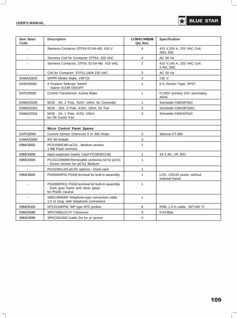
109
USER'S MANUAL
Item Baan Description LCWX2-345DiB SpecificationCode Qty Nos.
- Siemens Contactor 3TF54 02-0A-M0, 415 V 4 415 V,250 A, 220 VAC Coil,2NO, 2NC
- Siemens Coil for Contactor 3TF54, 220 VAC 4 AC 50 Hz
- Siemens Contactor, 3TF51 02-0A-M0 415 VAC 2 415 V,140 A, 220 VAC Coil,2 NO, 2NC
- Coil for Contactor, 3TF51,140A 220 VAC 2 AC 50 Hz
EAMAZ0525 SP/PR Minilec Make, VSP D1 2 230 V
EASHZ0060 4 Position Selector Switch 1 5 A, Rocker Type, SPST - Salzer 61198 ON/OFF
EATDZ0020 Control Transformer, Kavita Make 1 0-230V primary 24V secondary,40VA
EAMAZ0205 MCB - 4A, 2 Pole, 415V, 10KA, for Controller 1 Schneider C60H2P4AC
EAMAZ0316 MCB - 16A, 3 Pole, 415V, 10KA, for Fan 4 Schneider C60H3P16AC
EAMAZ0316 MCB - 2A, 1 Pole, 415V, 10KA, 2 Schneider C60H1P2ACfor Oil Cooler Fan
Micro Control Panel Spares
EATFZ0050 Current Sensor (Samcon) 0 to 300 Amps. 2 Samcon CT-300
EAMAZ0550 INT 69 module 2
EBMCI0002 PCO1000CM0 pCO1 - Medium version, 11 MB Flash memory
EBMCI0009 Input expansion board, Carel PCOE00TLN0 1 24 V AC, I/P, R/O
EBMCI0004 PCO1CON0M0 Removable connector kit for pCO1 1- Screw version for pCO1 Medium
- PCO100CLK0 pCOC options - Clock card 1
EBMCI0003 PGD0000F01 PGD0 terminal for built-in assembly 1 LCD, 120x32 pixels, withoutexternal frame
- PGD000FR11 PGD0 terminal for built-in assembly 1- Dark grey frame and silver glassfor PGD0, neutral
- S90CONN000 Telephone-type connection cable, 11.5 m long, with telephone connectors
EBMCI0100 NTC015WP00 WP type NTC probes 6 IP68, 1.5 m cable, -50T105 °C
EBMCI0080 SPKT00B1C0 Pr Transducer 4 0-44.8bar
EBMCI0090 SPKC002300 Cable 2m for pr sensor 4

110
SCREW CHILLER (Air & Water Cooled)
Spares for LCWX1-225 D i B & LCAX1-206 D i AItem Baan Description LCWX1-225DiB LCAX1-206DiA SpecificationCode Qty Nos. Qty Nos.
CDSAI0091 BSC-210A (RC-20) Compressor 1 1 Vi - 3.0
3105-1004a-3 4"Gasket for Discharge Flange 1 1 Reinz-Afm 34, 1.5t
3107-1143a Oil Filter 1 1
3107-1146a Inner Gasket of Oil Filter Flange 1 1 Teflon 1.5t
3101-1051B Oil Heater (220V) 1 1 220V,150W
4804-01 Oil Sight Glass (O-Ring included) 1 1 ALCO
3101-1006a-3 Gasket (For Motor Cable Cover Plate) 1 1 Reinz-Afm 34, 1.5t
EASCZ0010 Solenoid Coil for RC comprs. 3 3 220V, SANLAN SMG 1
4401-30 Solenoid Valve 3 3 2743K0R30-4344 SDH12223DS
3101-1003a Solenoid Valve Gasket 3 3 Nok,1515sps
3107-1054a Gasket For Suction Filter 1 1 Φ161.5*1.5t
3107-1024c Suction Filter 1 1 Φ159*210l
4405-56 Oil Level Switch 1 1 Rfs-8-2, 1200mm
CDSPI0710 Blue Star ACS Oil 18 liters 18 liters
Controls & Accessories Spares
RDEAI0070 Sporlan Expansion Valve - VVE-100 2 2
EASBI0140 Sporlan SV B10 S2 Solenoid Valve for Liq. Inj. 1 1
EASBI0145 Sporlan SV B10 S2 Solenoid Valve Coil 1 1
EASBI0190 Sporlan SV B19 S2 Solenoid Valve - 1for Economiser
EASBI0195 Sporlan SV B19 S2 Solenoid Valve Coil - 1
FEDBI0140 CTG Dehydrator (Core) 4 6
RDEAI0125 Sporlan Expansion Valve MVE-21 for economiser 1 1
VAAAZ2010 Valve Angle 1/4 6 6
RDEAI0120 Danfoss Expansion Valve TDEX-11 for liq. Inj. 1 1
EASBZ0040 Pilot Sol. Valve (230V) - 1 SANLAN 1/4" SAE Flare,15/240/50 MKC-2 Coil
FAPAZ7020 Bird Wing Fan - 12
Electrical Spares
FAPAZ7018 Motor for Condenser - 12 1.2 kW, 2.6 A, 700 RPM,400V/ 3 Ph./ 50 Hz
MBSAZ1800 Oil Cooler Fan Motor Assembly - 2 1 phase, 230 V, 90 W, 1350RPM, 450 mm dia.,VBM, FA 23/4514/K5/F
EAMAZ0605 Siemens Contactor, 3TF32 00-0A-M0 415 VAC - 3 415 V,16 A, 220 VAC Coilfor condenser fan
EAMAZ0606 Coil for Contactor 3TF32, 16A, 220 VAC - 3 AC 50 Hz
EATCZ0010 Star Delta Timer Siemens 3RP15 76-1NP30 1 1 24 VAC, 3-60 Seconds,1 NO Inst. & 1 NO Delayed
EAMAZ0610 SFU switch 630 Amp, 3 pole, 80KA - 1 Siemens 3KL8421-3UJ00

111
USER'S MANUAL
Item Baan Description LCWX1-225DiB LCAX1-206DiA SpecificationCode Qty Nos. Qty Nos.
EAMAZ0620 Fuse Link for 630 Amp SFU - 1
EAMAZ0595 SFU switch 400 Amp.3 pole, 80KA 1 - Siemens 3KL8341-3UJ00
EAMAZ0597 Fuse link for 400 Amp. SFU 1 -
EAMAZ0603 Siemens Contactor 3TF53 02-0A-M0, 415 VAC 2 - 415 V,205 A, 220 VAC Coil,2 NO, 2NC
EAMAZ0604 Coil for Contactor, 3TF53/205A, 220 V 2 - AC 50 Hz
EAMAZ0591 Siemens Contactor, 3TF50 02-0A-M0, 415 VAC 1 - 415 V,110 A, 220 VAC Coil,2NO, 2NC
EAMAZ0598 Coil for Contactor, 3TF50, 110A, 220 V 1 - AC 50 Hz
EAMAZ0603 Siemens Contactor 3TF55 02 0A-M0 415 V - 2 415 V,300 A, 220 VAC Coil,2NO, 2NC
EAMAZ0604 Coil for Contactor, 3TF55, 300A 220 VAC - 2 AC 50 Hz
EAMAZ0601 Siemens Contactor, 3TF52-02-0A-M0 415 V - 1 415 V,170 A, 220 VAC Coil,2NO, 2NC
EAMAZ0602 Coil for Contactor, 3TF52 170A 220 VAC - 1 AC 50 Hz
EAMAZ0525 SP/PR Minilec Make, VSP D1 1 1 230 V
EASHZ0060 4 Position Selector Switch - Salzer 61198 1 1 5 A, Rocker Type, SPSTON/OFF
EATDZ0020 Control Transformer, Kavita Make 1 1 0-230V primary 24Vsecondary, 40VA
EAMAZ0205 MCB - 4A, 2 Pole, 415V, 10KA, for Controller 1 1 Schneider C60H2P4AC
EAMAZ0316 MCB - 16A, 3 Pole, 415V, 10KA, for Fan - 3 Schneider C60H3P16AC
EAMAZ0316 MCB - 2A, 1 Pole, 415V, 10KA, - 1 Schneider C60H1P2ACfor Oil Cooler Fan
Micro Control Panel Spares
EATFZ0050 Current Sensor (Samcon) 0 to 300 Amps. 1 - Samcon CT-300
EATFZ0060 Current Sensor (Samcon) 0 to 500 Amps. - 1 Samcon CT-500
EAMAZ0550 INT 69 module 1 1
EBMCI0002 PCO1000CM0 pCO1 - Medium version, 1 11 MB Flash memory
EBMCI0004 PCO1CON0M0 Removable connector kit for 1 1pCO1 - Screw version for pCO1 Medium
- PCO100CLK0 pCOC options - Clock card 1 1
EBMCI0003 PGD0000F01 PGD0 terminal for built-in assembly 1 1 LCD, 120x32 pixels, withoutexternal frame
- PGD000FR11 PGD0 terminal for built-in assembly 1 1- Dark grey frame and silver glassfor PGD0, neutral
- S90CONN000 Telephone-type connection cable, 1 11.5 m long, with telephone connectors
EBMCI0100 NTC015WP00 WP type NTC probes 3 4 IP68, 1.5 m cable, -50T105 °C
EBMCI0080 SPKT00B1C0 Pr Transducer 2 2 0-44.8bar
EBMCI0090 SPKC002300 Cable 2m for pr sensor 2 2
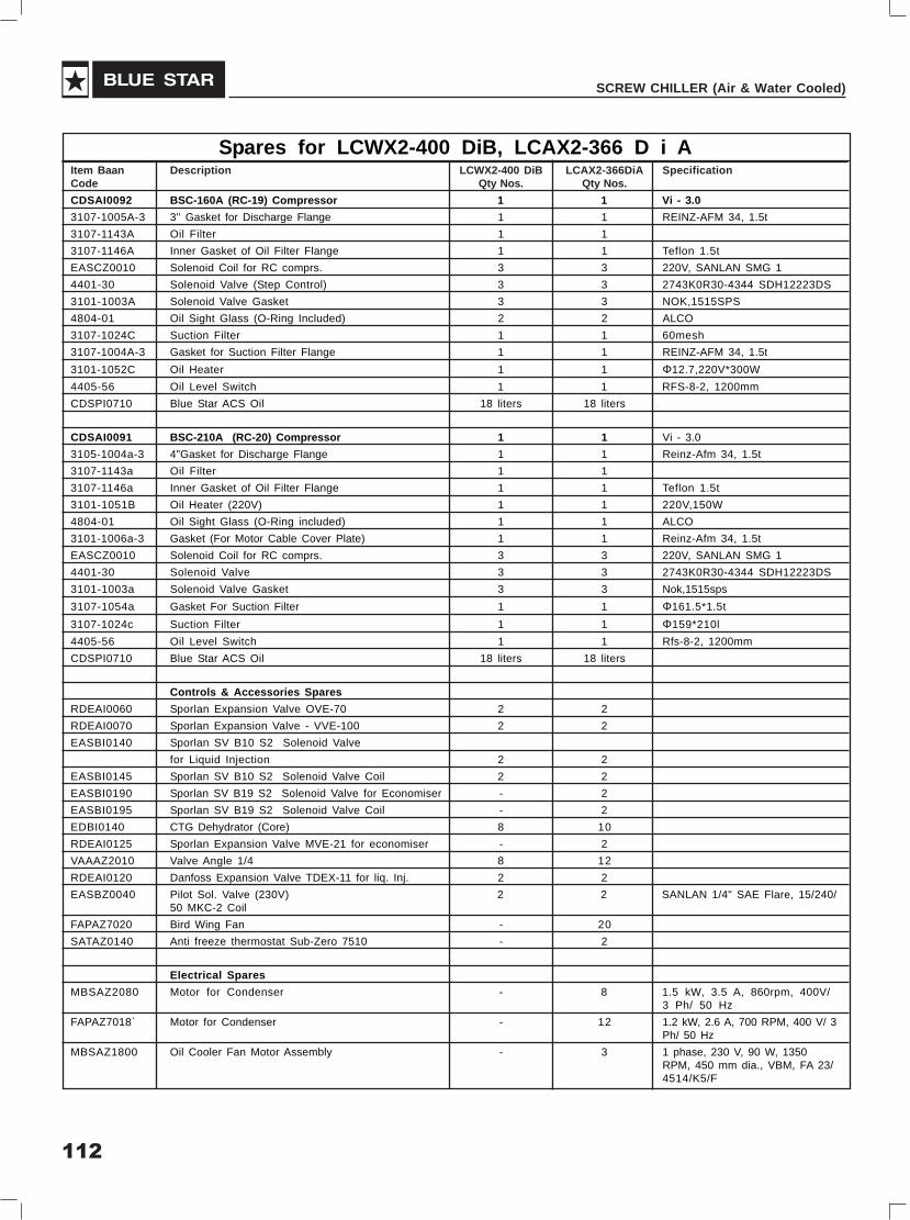
112
SCREW CHILLER (Air & Water Cooled)
Spares for LCWX2-400 DiB, LCAX2-366 D i AItem Baan Description LCWX2-400 DiB LCAX2-366DiA SpecificationCode Qty Nos. Qty Nos.
CDSAI0092 BSC-160A (RC-19) Compressor 1 1 Vi - 3.0
3107-1005A-3 3'’ Gasket for Discharge Flange 1 1 REINZ-AFM 34, 1.5t
3107-1143A Oil Filter 1 1
3107-1146A Inner Gasket of Oil Filter Flange 1 1 Teflon 1.5t
EASCZ0010 Solenoid Coil for RC comprs. 3 3 220V, SANLAN SMG 1
4401-30 Solenoid Valve (Step Control) 3 3 2743K0R30-4344 SDH12223DS
3101-1003A Solenoid Valve Gasket 3 3 NOK,1515SPS
4804-01 Oil Sight Glass (O-Ring Included) 2 2 ALCO
3107-1024C Suction Filter 1 1 60mesh
3107-1004A-3 Gasket for Suction Filter Flange 1 1 REINZ-AFM 34, 1.5t
3101-1052C Oil Heater 1 1 Φ12.7,220V*300W
4405-56 Oil Level Switch 1 1 RFS-8-2, 1200mm
CDSPI0710 Blue Star ACS Oil 18 liters 18 liters
CDSAI0091 BSC-210A (RC-20) Compressor 1 1 Vi - 3.0
3105-1004a-3 4"Gasket for Discharge Flange 1 1 Reinz-Afm 34, 1.5t
3107-1143a Oil Filter 1 1
3107-1146a Inner Gasket of Oil Filter Flange 1 1 Teflon 1.5t
3101-1051B Oil Heater (220V) 1 1 220V,150W
4804-01 Oil Sight Glass (O-Ring included) 1 1 ALCO
3101-1006a-3 Gasket (For Motor Cable Cover Plate) 1 1 Reinz-Afm 34, 1.5t
EASCZ0010 Solenoid Coil for RC comprs. 3 3 220V, SANLAN SMG 1
4401-30 Solenoid Valve 3 3 2743K0R30-4344 SDH12223DS
3101-1003a Solenoid Valve Gasket 3 3 Nok,1515sps
3107-1054a Gasket For Suction Filter 1 1 Φ161.5*1.5t
3107-1024c Suction Filter 1 1 Φ159*210l
4405-56 Oil Level Switch 1 1 Rfs-8-2, 1200mm
CDSPI0710 Blue Star ACS Oil 18 liters 18 liters
Controls & Accessories Spares
RDEAI0060 Sporlan Expansion Valve OVE-70 2 2
RDEAI0070 Sporlan Expansion Valve - VVE-100 2 2
EASBI0140 Sporlan SV B10 S2 Solenoid Valve
for Liquid Injection 2 2
EASBI0145 Sporlan SV B10 S2 Solenoid Valve Coil 2 2
EASBI0190 Sporlan SV B19 S2 Solenoid Valve for Economiser - 2
EASBI0195 Sporlan SV B19 S2 Solenoid Valve Coil - 2
EDBI0140 CTG Dehydrator (Core) 8 10
RDEAI0125 Sporlan Expansion Valve MVE-21 for economiser - 2
VAAAZ2010 Valve Angle 1/4 8 12
RDEAI0120 Danfoss Expansion Valve TDEX-11 for liq. Inj. 2 2
EASBZ0040 Pilot Sol. Valve (230V) 2 2 SANLAN 1/4" SAE Flare, 15/240/50 MKC-2 Coil
FAPAZ7020 Bird Wing Fan - 20
SATAZ0140 Anti freeze thermostat Sub-Zero 7510 - 2
Electrical Spares
MBSAZ2080 Motor for Condenser - 8 1.5 kW, 3.5 A, 860rpm, 400V/3 Ph/ 50 Hz
FAPAZ7018` Motor for Condenser - 12 1.2 kW, 2.6 A, 700 RPM, 400 V/ 3Ph/ 50 Hz
MBSAZ1800 Oil Cooler Fan Motor Assembly - 3 1 phase, 230 V, 90 W, 1350RPM, 450 mm dia., VBM, FA 23/4514/K5/F
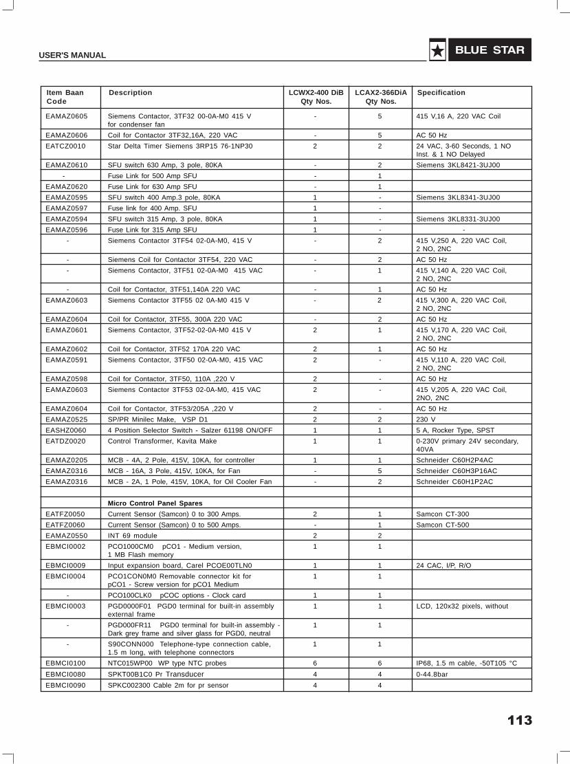
113
USER'S MANUAL
Item Baan Description LCWX2-400 DiB LCAX2-366DiA SpecificationCode Qty Nos. Qty Nos.
EAMAZ0605 Siemens Contactor, 3TF32 00-0A-M0 415 V - 5 415 V,16 A, 220 VAC Coilfor condenser fan
EAMAZ0606 Coil for Contactor 3TF32,16A, 220 VAC - 5 AC 50 Hz
EATCZ0010 Star Delta Timer Siemens 3RP15 76-1NP30 2 2 24 VAC, 3-60 Seconds, 1 NOInst. & 1 NO Delayed
EAMAZ0610 SFU switch 630 Amp, 3 pole, 80KA - 2 Siemens 3KL8421-3UJ00
- Fuse Link for 500 Amp SFU - 1
EAMAZ0620 Fuse Link for 630 Amp SFU - 1
EAMAZ0595 SFU switch 400 Amp.3 pole, 80KA 1 - Siemens 3KL8341-3UJ00
EAMAZ0597 Fuse link for 400 Amp. SFU 1 -
EAMAZ0594 SFU switch 315 Amp, 3 pole, 80KA 1 - Siemens 3KL8331-3UJ00
EAMAZ0596 Fuse Link for 315 Amp SFU 1 - -
- Siemens Contactor 3TF54 02-0A-M0, 415 V - 2 415 V,250 A, 220 VAC Coil,2 NO, 2NC
- Siemens Coil for Contactor 3TF54, 220 VAC - 2 AC 50 Hz
- Siemens Contactor, 3TF51 02-0A-M0 415 VAC - 1 415 V,140 A, 220 VAC Coil,2 NO, 2NC
- Coil for Contactor, 3TF51,140A 220 VAC - 1 AC 50 Hz
EAMAZ0603 Siemens Contactor 3TF55 02 0A-M0 415 V - 2 415 V,300 A, 220 VAC Coil,2 NO, 2NC
EAMAZ0604 Coil for Contactor, 3TF55, 300A 220 VAC - 2 AC 50 Hz
EAMAZ0601 Siemens Contactor, 3TF52-02-0A-M0 415 V 2 1 415 V,170 A, 220 VAC Coil,2 NO, 2NC
EAMAZ0602 Coil for Contactor, 3TF52 170A 220 VAC 2 1 AC 50 Hz
EAMAZ0591 Siemens Contactor, 3TF50 02-0A-M0, 415 VAC 2 - 415 V,110 A, 220 VAC Coil,2 NO, 2NC
EAMAZ0598 Coil for Contactor, 3TF50, 110A ,220 V 2 - AC 50 Hz
EAMAZ0603 Siemens Contactor 3TF53 02-0A-M0, 415 VAC 2 - 415 V,205 A, 220 VAC Coil,2NO, 2NC
EAMAZ0604 Coil for Contactor, 3TF53/205A ,220 V 2 - AC 50 Hz
EAMAZ0525 SP/PR Minilec Make, VSP D1 2 2 230 V
EASHZ0060 4 Position Selector Switch - Salzer 61198 ON/OFF 1 1 5 A, Rocker Type, SPST
EATDZ0020 Control Transformer, Kavita Make 1 1 0-230V primary 24V secondary,40VA
EAMAZ0205 MCB - 4A, 2 Pole, 415V, 10KA, for controller 1 1 Schneider C60H2P4AC
EAMAZ0316 MCB - 16A, 3 Pole, 415V, 10KA, for Fan - 5 Schneider C60H3P16AC
EAMAZ0316 MCB - 2A, 1 Pole, 415V, 10KA, for Oil Cooler Fan - 2 Schneider C60H1P2AC
Micro Control Panel Spares
EATFZ0050 Current Sensor (Samcon) 0 to 300 Amps. 2 1 Samcon CT-300
EATFZ0060 Current Sensor (Samcon) 0 to 500 Amps. - 1 Samcon CT-500
EAMAZ0550 INT 69 module 2 2
EBMCI0002 PCO1000CM0 pCO1 - Medium version, 1 11 MB Flash memory
EBMCI0009 Input expansion board, Carel PCOE00TLN0 1 1 24 CAC, I/P, R/O
EBMCI0004 PCO1CON0M0 Removable connector kit for 1 1pCO1 - Screw version for pCO1 Medium
- PCO100CLK0 pCOC options - Clock card 1 1
EBMCI0003 PGD0000F01 PGD0 terminal for built-in assembly 1 1 LCD, 120x32 pixels, withoutexternal frame
- PGD000FR11 PGD0 terminal for built-in assembly - 1 1Dark grey frame and silver glass for PGD0, neutral
- S90CONN000 Telephone-type connection cable, 1 11.5 m long, with telephone connectors
EBMCI0100 NTC015WP00 WP type NTC probes 6 6 IP68, 1.5 m cable, -50T105 °C
EBMCI0080 SPKT00B1C0 Pr Transducer 4 4 0-44.8bar
EBMCI0090 SPKC002300 Cable 2m for pr sensor 4 4

114
SCREW CHILLER (Air & Water Cooled)
Field Feed Back Card on Receipt of Chiller at SiteReturn To : Manufacturing Unit - Thane
PRODUCT :
CHILLER MODEL :
SR. NO. :
CUSTOMER NAME : LOCATION :
DATE :
Observation Comments Details Of Defects
Quality of Packing Ok / Damaged
Receipt of Documents
- Packing List Yes / No
- Test Report Yes / No
- Truck No.
Condition of Parts :
- Frame Work Ok /
- Condenser coils Ok /
- Fan Mountings Ok /
- Springs Ok /
- Compressor Ok /
- Condenser Ok /
- Cooler Ok /
- Electrical Panel Ok /
- Oil Cooler Ok /
- Economiser Ok /
- Refrigerant Piping Ok /
- Idle Pressure Ok /
REMARKS :
The field feed back card as per the format below shall be send to factory on receiptof the Chiller
Checked By
For Factory Use :
- Date of Receipt : - Action By :
- Comments :
Field Feed Back Form

115
USER'S MANUAL
Field Feedback Card - Commissioning of Chiller at Site
Product : Air Cooled / Water Cooled Screw Chiller
Chiller Model :
Sr. No. :
Customer Name : Location :
Engineer’s Name :
Observation Comments Remarks
Installation/Precommissioning Checks :
- Unit Installed and levelled Ok /
- Condenser water connection terminatedproperly with isolation required
- Chilled water connection terminatedproperly with isolation required Ok /
- Electrical connection with Earthingterminated properly Ok /
- Condenser water and Chilled water systemproperly flushed Ok /
- Water Quality checked Ok /
- Insulation Resistance of Cables checked Ok /
- Condenser water and Chilled water Pumpcommissioned Ok /
Water flow adjusted to the design flow bychecking pressure drop Ok /
Water flow switches connected withelectrical panel Ok /
Check up Voltage Ok / Starting 400V + 10% Running 400V + 10%
Commissoned the Chiller Ok / Long term running 400V ± 5%
Noise Level Ok /
Vibration Ok /
Check Current Ok /
Testing done at site Ok /
Performance data as per format Ok /
- Commissioning Date
- Commissioning By
Remarks :
Note : Warranty will be valid only after receipt of this card at the factoryFor Factory Use :
- Date Of Receipt : - Action By :
- Comments :
The field feedback card as per the format below shall be sent to factoryafter Commisioning of the Chiller

116
SCREW CHILLER (Air & Water Cooled)
Hand over the Chiller to the Customer as per the format below and establish WarrantyCOMMISSIONING & HANDING OVER REPORT
BLUE STAR LIMITEDOur Ref: Date:
Cust. Ref.
PURCHASE ORDER Date:
Date:
Equipment : Blue Star make Air / Water Cooled Screw Chiller
Model:
Sl.Nos.
Customer Name & Address
Equipment location :
Call made by
COMMISSIONING
Service renderedSupplied,Installed,Tested and Commissioned Blue Star make Air Cooled Screw Chillers / Water CooledScrew Chillers and they are put into regular operation. The Model No. & Serial Nos. of the units are givenbelow :
CHILLER MODEL :
SERIAL NO. OF MACHINE NO.1 :
SERIAL NO. OF MACHINE NO.2 :
The chillers are handed over to the customer for the beneficial use.
Equipment warranty expires on : Attended by: Blue Star Ltd. Signature:
For office use: The above equpiment has been installed andcommissioned to our satisfaction.
Other comments (if any).
Date : Customer’s Stamp & Signature
5091-10C Registered Office : Kasthuri Buildings, Jamshedji Tata Road, Mumbai 400 020
Commissioning andHanding Over

117
USER'S MANUAL
Recommended Water Quality Standards
Test items Chilled Cooling Tower MakeupWater Quality Water Quality Water Quality
pH 7.2 - 8.5 7.2 - 8.5 6.0 - 8.0
Total hardness
(CaCo3) ppm Max. 80 Less than 200 Max. 50
Total Alkalinity
(CaCo3) ppm Less than 100 Less than 100 Less than 80
Chloride Ion (ppm) Less than 50 Less than 200 Less than 50
Total Ion (Fe) ppm Less than 0.3 Less than 1.0 Less than 0.3
Silica (Sio2) ppm Less than 30 Less than 50 Less than 30
Ammonium Ion ppm Less than 0.2 Less than 1.0 Less than 0.2
Water Quality

118
SCREW CHILLER (Air & Water Cooled)
Log Report
Customer's Name
Date:
Time
S.No Description Units 10.00 12.00 14.00 16.00 18.00
1 Voltage R-Y Volts
Voltage Y-B Volts
Voltage R-B Volts
2 Current - R Amps.
Current - Y Amps.
Current - B Amps.
3 Supply Frequency Hz
4 Suction Pressure comp. PSIG
5 Discharge Pressure comp. PSIG
6 Compressor Current. Amps.
7 Cooler Entering Water temp. 0F
8 Cooler Leaving Water temp. 0F
9 Cooler Pressure drop PSIG
10 Cooler water Flow rate US GPM
11 Condenser Entering water temp. 0F
12 Condenser Leaving water temp. 0F
13 Condenser Pressure drop PSIG
14 Condenser water Flow rate US GPM
15 Refri. System temp. - Suction 0F
16 Refri. System temp.-Discharge. 0F
17 Refri. System temp. - Liquid 0F

119
USER'S MANUAL
Warranty Claim FormFor Blue Star Air / Water Cooled Screw Chillers
A copy of this form is to be filled in case of the Chiller failure, by BSL Engineer)
Location (City) ……......……………. Date ………...…….
Chiller Model No:
Date of despatch
Warranty commencing date
Application in which equipment is used
Chiller Serial No.
Date of commissioning
Warranty expiry date
Any vibration in piping � Yes � No
Less cooling in cooler � Yes � No
Checked Water flow rate � Yes � No
Checked Compressor working in full Load � Yes � No
Operating pressure checked � Yes � No
Shortage of refrigerant � Yes � No
Electrical problem � Yes � No
Voltage � � YesNo
Insulation resistance (Megger test)…………….....…….. Ohms
Customer’s Name and Address Dealer’s Name and Address
Starting Problem � Yes � No
Noise at Starting � Yes � No
Noise while running � Yes � No
Signature & Seal of Customer Signature & Seal of BSL Engineer
Date ……………. Date …………………….
(For Factory use only)
Claim settled � Credit advice No. …....................................…… Claim rejected �
Reasons for rejection ……………………....................................................................................
Settlement authorised by : ……......……………….. Date …………………………….
Compressor : � High Noise � Vibration
Any mounting bolts loose : � Yes � No

120
SCREW CHILLER (Air & Water Cooled)
WarrantyBlue Star Screw Chillers carry a warranty for a period of 12 months from the date of commissioning or 15months from the date of delivery, whichever is earlier, unless stated otherwise in the contract of sales.
Terms of WarrantyBlue Star extends a comprehensive warranty on its systems, which entitles the customer to the following
1. Repair / reconditioning, by BSL / BSL Dealer, through whom the machine has been purchased, of anypart of the equipment found defective within 12 months from the date of commissioning or 15 monthsfrom the date of despatch whichever is earlier.
2. The warranty is valid only if:
2.1. Installation and commissioning is taken care of by BSL/their authorised persons.
2.2. The equipment is operated as per the Company’s operating instructions.
3. The above said warranty does not cover the following:
3.1 Any leakage of Refrigerant due to improper operations
4. This warranty is not valid if any repair and/or modifications are carried out by the customer himself orhis representative without written concurrence from Blue Star Limited.
5. The warranty extended herein is in lieu of all implied conditions/warranties under the law and is confinedto the repairs or replacements of defective parts and does not cover any consequential or resulting liabilitydamage or loss arising from such defect. Furthermore, the warranty in no case, shall extend to thepayment or any monetary consideration whatever of the replacement or return of the Screw Chiller asa whole
6. Any repair/ replacement shall not extend the overall warranty period as specified above.
7. The cost of transportation of material and of persons beyond Municipal jurisdiction shall be borne by thecustomer.
8. This warranty may be read in conjunction with any other warranty on the installation as a whole, ifthe Screw Chiller is supplied as part of a Project.

121
USER'S MANUAL
EAST
BHUBANESHWAR3A, Satya Nagar,2nd Floor,Bhubaneswar 751 007.Tel: (0674) 2508270 / 2508303
GUWAHATINew Star Freeze Building2nd Floor,Opp. Kunjalata Bibah Bhawan,G. S. Road,Guwahati 781 005.Tel: (0361) 2340619 / 2340620
KOLKATA7, Hare StreetKolkata 700 001.Tel: (033) 22134200 /22106609
NORTH
CHANDIGARHSCO 1, Madhya Marg, Sector 26Chandigarh 160 019.Tel: (0172) 2790482 / 5024000
JAIPURA-19, Main Sahakar Path,Near Sahakar Bhawan,Jaipur - 302 001.Tel: (0141) 2744033
LUCKNOWB-140, Nirala NagarLucknow 226 020.Tel: (0522) 2786172 / 2787274
NEW DELHIE-44/12 Okhla Ind. AreaPhase II, OhklaNew Delhi 110 020.Tel: (011) 41494200 / 000
Service Centres
SOUTH
BANGALOREOzone Manay Technology ParkSy. No. 56/18 & 55/9Hongasandra VillageBegur Hobli, GarvebhavipalyaBangalore – 560 068Phone : 41854000
CHENNAI104, ‘Garuda Building’,Cathedral Road,Chennai 600 086.Tel: (044) 42444200 28116707- 8
KOCHI39/5766, Tharakandam EstateKurisipally RoadKochi 682 015.Tel: (0484) 2356139 /2357933 / 2357934
SECUNDERABAD207, Sikh RoadBantia EstatesSecunderabad 500 003.Tel: (040) 44004000
TRIVANDRUMT.C. IX/1490‘Chandrika’, SasthamangalamTrivandrum 695 010.Tel: (0471) 2720025 / 2720065
VISAKHAPATNAM47-12-6/72nd FloorAmaravathi ComplexDwarakanagarVisakhapatnam 530 016.Tel: (0891) 2748405 / 2748433
WEST
BHOPAL“Star Arcade”, 2nd FloorPlot No.165A & 166, Zone-IMaharana Pratap NagarBhopal 462 011.Tel: (0755) 2553378 /4273378 / 79
GOA1st Floor, Flat No.1Buddhaseth Apartments, Tonca,Caranzalem, Goa 403 002.Tel: (0832) 2461671 / 2462087
MUMBAIBlue Star House9A, Ghatkopar Link RoadSaki Naka, Mumbai 400 072.Tel: (022) 66684200 / 66684000
NAGPUR219, Bajaj Nagar, 1st Floor,South Ambazari Road,Nagpur 440 010.Tel: (0712) 2229244 / 2249000
PUNE201/A, Nityanand Complex1st Floor, 247/ABund Garden RoadPune 411 001.Tel: (020) 26167230/ 26163031 / 26162307
VADODARARamakrishna Chambers7th Floor, Productivity RoadAlkapuri, Vadodara 390 005.Tel: (0265) 2338561 /2332021 / 2332022

122
SCREW CHILLER (Air & Water Cooled)
For anyassistance,
CALL:
Blue Star Service:
Ph: ............................................................
Cell: ..........................................................
Blue Star Dealer:
Ph: ............................................................
Cell: ..........................................................
Blue Star Regional Manager:
Ph: ............................................................
Fax: ..........................................................
Blue Star’s/Dealer’s engineer to fillabove details before handing over
this Manual to customer.

123
USER'S MANUAL
B R E A T H E E A S Y