blxx-pg-en-v3 - programmable codesys v3 gatewayspdb2.turck.de/repo/media/_en/anlagen/d301373.pdf ·...
TRANSCRIPT
Your Global Automation Partner
BLxx-PG-EN-V3 Programable CODESYS 3 gateways
User manual

Prog
ram
mab
le G
atew
ays
BLxx
-PG
-EN
-V3
1 About this manual 5
1.1 Documentation concept 5
1.1.1 Additional documentation 5
1.2 Explanation of symbols used 5
1.2.1 Warnings 51.2.2 Further notes 6
1.3 General notes 7
1.3.1 Prescribed use 71.3.2 Notes concerning planning/installation of this product 7
2 General function description 9
2.1 Function description 9
3 Hardware description 11
3.1 Device structure 11
3.2 Device dimensions 11
3.3 Block diagrams 12
3.4 Technical data 13
3.4.1 BL20-PG-EN-V3 133.4.2 BL67-PG-EN-V3 15
3.5 Connectors 17
3.5.1 Fieldbus connection 173.5.2 Power supply 183.5.3 USB Device port 183.5.4 USB Host port 19
3.6 Device addressing and operation mode setting 19
3.6.1 Restore IP 203.6.2 Address setting via rotary coding switches (Static rotary) 203.6.3 Address setting via the mode DHCP 213.6.4 Address setting via the mode PGM 213.6.5 Address setting via the mode PGM-DHCP (universal mode) 223.6.6 F_Reset (Reset to factory setting) 233.6.7 Address setting with Turck IP Address Tool 243.6.8 Address setting via DTM 26
3.7 SET button 28
3.8 Reset to factory settings 29
3.8.1 IP Address Tool 293.8.2 Web server 30
3.9 LED displays 31
1V01.00 | 2016/06

3.9.1 LED description BL20 313.9.2 LED description BL67 33
3.10 Real time clock (RTC) 35
3.11 SFTP access 36
3.12 Firmware update 37
3.12.1 Firmware update using USB storage device 373.12.2 Firmware update via DTM 37
4 Parameters and diagnostics 39
4.1 Parameters 39
4.2 Diagnostics 40
4.2.1 System diagnostics 404.2.2 I/O diagnostics 41
5 CODESYS-functions 43
5.1 Supported CODESYS libraries 43
5.2 General start-up 44
5.2.1 Installing the device package in CODESYS 445.2.2 Standard project with BLxx-PG-EN-V3 in CODESYS V3.5.8.10 45
5.3 Modbus TCP-Master 46
5.3.1 Configuring the Modbus TCP-Master 465.3.2 Configuring the external Modbus TCP slave 47
5.4 Modbus TCP-Slave-Device 49
5.4.1 Configuring Modbus TCP-Slave-Device 49
5.5 PROFINET-Device 51
5.5.1 Configuring the PROFINET-device in CODESYS 515.5.2 Configuring the PROFINET-device in the PROFINET-master 53
5.6 EtherNet/IP™ Slave (Device) 56
5.6.1 Configuring the EtherNet/IP™-device in CODESYS 565.6.2 Configuring the EtherNet/IP™-slave in EtherNet/IP™ PLC 58
6 USB Host port functions 61
6.1 Compatible storage devices 61
6.2 Functions of the USB Host port 61
6.2.1 General hints/prerequisites 626.2.2 Function overview 636.2.3 Executing the functions 656.2.4 Behavior of the RUN-LED in case of an error 66
Hans Turck GmbH & Co. KG | T +49 208 4952-0 | F +49 208 4952-264 | [email protected] | www.turck.com2

Prog
ram
mab
le G
atew
ays
BLxx
-PG
-EN
-V3
7 The web server 67
7.1 Web server - remote access/configuration 67
7.2 Safety in the web server 67
7.3 IP address 67
7.4 Home 68
7.5 Gateway Diagnostics 69
7.6 Ethernet Statistics 70
7.7 Links 70
7.8 Login/password 71
7.9 Change Admin Password 71
7.10 Network Configuration 73
7.10.1 Change network parameters (port settings, IP address, etc.) 73
7.11 Gateway Configuration 74
7.11.1 Configuration of the field bus interface 747.11.2 Reboot 747.11.3 Reset to Factory Defaults 74
7.12 Slot Parameters 75
7.12.1 Parameterization of the in-/ outputs 75
7.13 Using mobile devices 76
7.14 Web server logout 76
7.15 Deactivating the web server 76
3V01.00 | 2016/06

Hans Turck GmbH & Co. KG | T +49 208 4952-0 | F +49 208 4952-264 | [email protected] | www.turck.com4

Prog
ram
mab
le G
atew
ays B
Lxx-
PG-E
N-V
3
1 About this manual
1.1 Documentation concept
This manual describes the hardware and the functions of the CODESYS V3-programmable gateways for the Turck product families BL20 and BL67 (BL20-PG-EN-V3 and BL67-PG-EN-V3).
The following chapters contain:
the hardware description of BLxx-PG-EN-V3,
the description of the device functionalities (master/device),
the description of the Modbus-master, page 46
examples for the connection of the BLxx-PG-EN-V3 as device (slave)
– Modbus TCP Slave Device, page 49
– PROFINET IO-Device, page 51
– EtherNet/IP™-Device, page 56
1.1.1 Additional documentationPlease read the following product family manuals for any general product line specific issues e.g. system description, mounting, electrical installation, station configuration etc.
BL20:
D300717 „BL20 I/O modules - hardware and engineering“
BL67:
D300529 „BL67 I/O modules - hardware and engineering“
1.2 Explanation of symbols used
1.2.1 WarningsAction-related warnings are placed next to potentially dangerous work steps and are marked by graphic symbols. Each warning is initiated by a warning sign and a signal word that expresses the gravity of the danger. The warnings have absolutely to be observed:
DANGER!DANGER indicates an immediately dangerous situation, with high risk, the death or severe injury, if not avoided.
WARNING!WARNING indicates a potentially dangerous situation with medium risk, the death or severe injury, if not avoided.
CAUTION!CAUTION indicates a potentially dangerous situation with low risk, middle or low injury, if not avoided.
5V01.0| 2016/04

About this manual
1.2.2 Further notes
CALL TO ACTION
This symbol identifies steps that the user has to perform.
RESULTS OF ACTION
This symbol identifies relevant results of steps
ATTENTION!ATTENTION indicates a situation that may lead to property damage, if it is not avoided.
NOTEIn NOTES you find tips, recommendations and important information. The notes facilitate work, provide more information on specific actions and help to avoid overtime by not fol-lowing the correct procedure.
TECHNICAL BASICSThe TECHNICAL BASICS offer technical information, basics and background information. This information lead to a better understanding of the device functions for example. The experienced user can skip this information.
Hans Turck GmbH & Co. KG | T +49 208 4952-0 | F +49 208 4952-264 | [email protected] | www.turck.com6

Prog
ram
mab
le G
atew
ays B
Lxx-
PG-E
N-V
3
1.3 General notes
Please read this section carefully. Safety aspects cannot be left to chance when dealing with electri-cal equipment.
This manual includes all information necessary for the prescribed use of the devices BL20-PG-EN-V3 and BL67-PG-EN-V3. It has been specially conceived for personnel with the necessary qualifications.
1.3.1 Prescribed use
The devices described in this manual must be used only in applications prescribed in this manual or in the respective technical descriptions, and only with certified components and devices from third party manufacturers.
Appropriate transport, storage, deployment and mounting as well as careful operating and thor-ough maintenance guarantee the trouble-free and safe operation of these devices.
1.3.2 Notes concerning planning/installation of this productAll respective safety measures and accident protection guidelines must be considered carefully and without exception.
7V01.0| 2016/04

About this manual
Hans Turck GmbH & Co. KG | T +49 208 4952-0 | F +49 208 4952-264 | [email protected] | www.turck.com8

Prog
ram
mab
le G
atew
ays B
Lxx-
PG-E
N-V
3
2 General function description
2.1 Function description
The programmable BL20/BL67 gateways can be used as autonomous PLCs or as decentral PLCs in a network interconnection for a fast preprocessing of signals. The programmable gateways allow autonomous control of applications without higher-level control.
The Ethernet ports serve as interface for programming, configuration and field bus communication.
Thanks to the multiprotocol Ethernet technology, the device can be used as slave with PLCs or PC based systems with PROFINET, EtherNet/IP™ or Modbus TCP. In addition to that, the device can be operated as Modbus TCP-master.
Gateways are the head component of a BL20 station. The electronic modules communicate over the internal module bus with the gateway and can be configured independently of the fieldbus proto-col.
Properties:
Programmable according to IEC 61131-3 with ODESYS V3 in:
– IL = Instruction List
– LD = Ladder Logic
– FBD = Function Block Diagram
– SFC = Sequential Function Chart
– ST = Structured Text
Ethernet- and programming interface
Integrated Gold CAP-buffered RTC (Real Time Clock)
USB Device Port as programming and service interface
USB Host Port for connecting USB memory sticks for firmware-update, program backup, program restore, data synchronization
Protocol converter - for example from Ethernet to serial communication.
LEDs for display of PLC status (LED APL, LED RUN), supply voltage (LED VI/VO, BL67 only), group(LED ERR) and bus errors (LED BUS)
Integrated Ethernet switch allows line topology
Integrated web server
Field bus connection
– BL67-PG-EN-V3: Ethernet, 2 x M12-female connector, 4-pol. D-codes
– BL20-PG-EN-V3: Ethernet, 2 x RJ45-ports,
Power supply
– BL67-PG-EN-V3: 5-pole 7/8"-connector
– BL20-PG-EN-V3: screw terminals
Protection class:
– BL67-PG-EN-V3: IP67
– BL20-PG-EN-V3: IP20
9V01.0| 2016/04

General function description
Hans Turck GmbH & Co. KG | T +49 208 4952-0 | F +49 208 4952-264 | [email protected] | www.turck.com10

Prog
ram
mab
le G
atew
ays B
Lxx-
PG-E
N-V
3
3 Hardware description
3.1 Device structure
3.2 Device dimensions
Fig. 1: Device structure BL20-PG-EN-V3 Fig. 2: Device structure BL67-PG-EN-V3
A USB Host portB DIP-switch for setting the operation modeC Rotary coding switch for address assignmentD Ethernet portsE Power supplyF USB-Device port (Service)G SET button
Fig. 3: Device dimensions BL20-PG-EN-V3 Fig. 4: Device dimensions BL67-PG-EN-V3
0 123
456789
0 123
456789
x10
PG-EN-V3
ETH1 UL
UL
USYS
SRV
ON OFF
USB Host
x1
GW IOsAPPL RUN
BUS LNK1ERR LNK2
+–+–
12345
A
GF
B
C
D
E
Power
ETH2
ETH1
0987
6 5 432
1
0987
6 5 432
1
12
34
5
PG-EN-V3
GW
IOBL67
RUNVI/VOAPPL
ERRBUS
LNK1LNK2
A
BC
D
E
F G
50.6
114.874.4
LEDLED
77.5
145
32
13
11V01.0| 2016/04

Hardware description
3.3 Block diagrams
Fig. 5: Block diagram BL20-PG-EN-V3
Fig. 6: Block diagram BL67-PG-EN-V3
ServiceUSB
USB-Host
Eth1
Eth2
USYS
UL
UL
GND
Switch
μC
5 VDC
24 VDC
RTC(buffered)
NV-RAM
Memory
Module businterface
Communikationbus
Power bus
BL20 system bus
ServiceUSB
USB-Host
Eth1
Eth2
UL
GND
Switch
μC
5 VDC
24 VDC
V0
VI Vsens
PE
GND
21
4 3
21
4 3
5
43
2
1
RTC(buffered)
NV-RAM
Memory
Module businterface
Communikationbus
Power bus
BL67 system bus
Short circuitprotection
Hans Turck GmbH & Co. KG | T +49 208 4952-0 | F +49 208 4952-264 | [email protected] | www.turck.com12

Prog
ram
mab
le G
atew
ays B
Lxx-
PG-E
N-V
3
3.4 Technical data
3.4.1 BL20-PG-EN-V3
Power supply
Power supply 24 VDC
System supply 24 VDC/5 VDC
Field supply 24 VDC
Permissible range 18...30 VDC
Nominal voltage from module bus 200 mA
Nominal current from module bus 8 A
Max. system supply current 1.3 A
Connection technology screw terminals
Field bus
Transmission rate 10/100 Mbps, Full/Half Duplex, Auto Negotiation, Auto Crossing
Address assignment Rotary coding switches, PGM, DHCP
Connection technology RJ45-connector
PLC data
Programming CODESYS 3
Released for CODESYS version from V 3.5.6.30
Programming IEC 61131-3 (IL, LD, FBD, SFC, ST)
OPC yes
OPC UA no
Application tasks 5
Programming interface Ethernet, USB
Processor ARM, 32 Bit
Cycle time < 1ms for 1000 IL- commands (without I/O cycle)
Real time clock (RTC) yes
Program memory 1024 kByte
Data memory 512 kByte
Input data 4 kByte
Output data 4 kByte
Non-volatile memory 16 kByte
Web server
Default IP address 192.168.1.254
Service interface Mini USB
13V01.0| 2016/04

Hardware description
Modbus TCP
Address assignment Static IP, BOOTP, DHCP
Supported Function Codes FC1, FC2, FC3, FC4, FC5, FC6, FC15, FC16, FC23
Input data size max. 1024 registers
Input register start address 0 (0x0000 hex)
Out data size max. 1024 registers
Output register start address 0 (0x0000 hex)
EtherNet/IP™
Address assignment according to EtherNet/IP™ standard
Input data size 248 INT
Out data size 248 INT
PROFINET
Address assignment DCP
Conformance Class B (RT)
MinCycleTime 1 ms
Diagnostics according to PROFINET Alarm Handling
Topology detection supported
Automatic address assignment supported
Input data size max. 512 byte
Out data size max. 512 byte
Ambient conditions
Operating temperature -20…+ 60 °C
Storage temperature -25…+70 °C
Relative humidity 15 to 95% (internal), Level RH-2, no condensation (at 45 °C storage)
Vibration test according to EN 61131
Shock test according to IEC 68-2-27
Drop and topple according to EN 68-2-31 and free fall according to IEC 68-2-32
Electro-magnetic compatibility according to IEC 61131-2
Protection class IP20
General
Dimensions (w × l × h) 50,6 × 114,8 × 74,4mm
Approvals CE
Hans Turck GmbH & Co. KG | T +49 208 4952-0 | F +49 208 4952-264 | [email protected] | www.turck.com14

Prog
ram
mab
le G
atew
ays B
Lxx-
PG-E
N-V
3
3.4.2 BL67-PG-EN-V3
Power supply
Power supply 24 VDC
System supply 24 VDC/5 VDC
Field supply 24 VDC
Permissible range 18...30 VDC
Nominal voltage from module bus 100 mA
max. sensor supply Isens 4 A electronic short circuit fuse
max. load current Io 10 A
Nominal current from module bus 10 A
Max. system supply current 1.2 A
Connection technology 5-pole 7/8"-connector
Field bus
Transmission rate 10/100 Mbps, Full/Half Duplex, Auto Negotiation, Auto Crossing
Address assignment Rotary coding switches, PGM, DHCP
Connection technology 2 x M12, 4-Pin, D coded
PLC data
Programming CODESYS 3
Released for CODESYS version from V 3.5.6.30
Programming IEC 61131-3 (IL, LD, FBD, SFC, ST)
OPC yes
OPC UA not supported
Application tasks 5
Programming interface Ethernet, USB
Processor ARM, 32 Bit
Cycle time < 1ms for 1000 IL- commands (without I/O cycle)
Real time clock yes
Program memory 1024 kByte
Data memory 512 kByte
Input data 4 kByte
Output data 4 kByte
Non-volatile memory 16 kByte
Web server
Default IP address 192.168.1.254
Service interface Mini USB
15V01.0| 2016/04

Hardware description
Modbus TCP
Address assignment Static IP, BOOTP, DHCP
Supported Function Codes FC1, FC2, FC3, FC4, FC5, FC6, FC15, FC16, FC23
Input data size max. 1024 registers
Input register start address 0 (0x0000 hex)
Out data size max. 1024 registers
Output register start address 0 (0x0000 hex)
EtherNet/IP™
Address assignment according to EtherNet/IP™ standard
Input data size 248 INT
Out data size 248 INT
PROFINET
Address assignment DCP
Conformance Class B (RT)
MinCycleTime 1 ms
Diagnostics according to PROFINET Alarm Handling
Topology detection supported
Automatic address assignment supported
Input data size max. 512 byte
Out data size max. 512 byte
Ambient conditions
Operating temperature -40…+70 °C
Temperature derating
> 55 °C Derating: max. field supply current = 5 A
Storage temperature -40…+85 °C
Relative humidity 15 to 95% (internal), Level RH-2, no condensation (at 45 °C storage)
Vibration test according to EN 61131
up to 5 g (at 10 to 150 Hz) for mounting on DIN rail no drilling according to EN 60715, with end bracket
up to 20 g (at 10 to 150 Hz) for mounting on base plate or machinery Therefore every sec-ond module has to be mounted with two screws each.
Shock test according to IEC 68-2-27
Drop and topple according to EN 68-2-31 and free fall according to IEC 68-2-32
Electro-magnetic compatibility according to IEC 61131-2
Protection class IP67
DIN rail mounting yes, please observe offset
Direct mounting two mounting holes, 6 mm Ø
General
Dimensions (w × l × h) 74 × 145 × 77.5mm
Approvals CE
Hans Turck GmbH & Co. KG | T +49 208 4952-0 | F +49 208 4952-264 | [email protected] | www.turck.com16

Prog
ram
mab
le G
atew
ays B
Lxx-
PG-E
N-V
3
3.5 Connectors
3.5.1 Fieldbus connection
BL20-PG-EN-V3
The field bus connection is realized via:
2 x RJ45-connector
BL67-PG-EN-V3
The field bus connection is realized via:
2 x M12 (female connector), M12-Ethernet switch, 4-pole, D-coded, according to IAONA specifica-tion
TX+ Transmission Data +
RX+ Receive Data +
TX- Transmission Data -
RX- Receive Data -
Signal Data
TX+ Transmission Data +
RX+ Receive Data +
TX- Transmission Data -
RX- Receive Data -
12345678
1 = TX +2 = TX –3 = RX +4 = n.c.5 = n.c.6 = RX –7 = n.c.8 = n.c.
�
� �
� ����� �� ������� �� ������� �� �������� �� ��
�
17V01.0| 2016/04
Hardware description
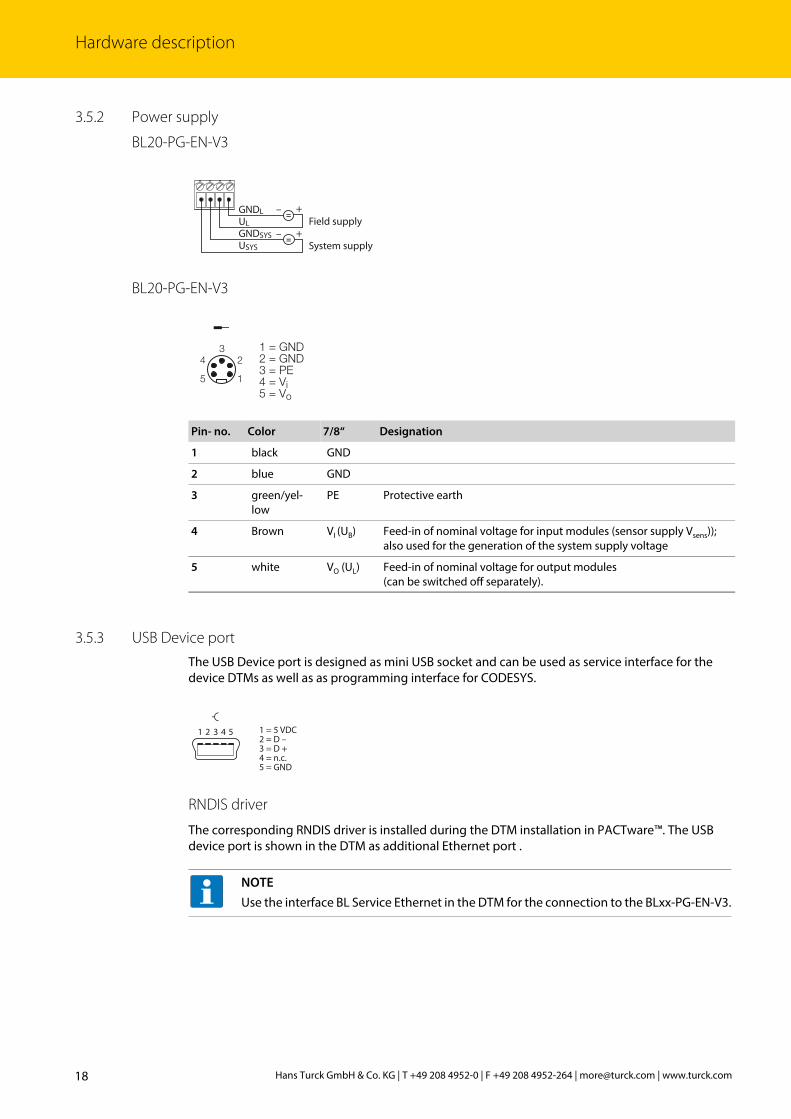
3.5.2 Power supply
BL20-PG-EN-V3
BL20-PG-EN-V3
3.5.3 USB Device portThe USB Device port is designed as mini USB socket and can be used as service interface for the device DTMs as well as as programming interface for CODESYS.
RNDIS driver
The corresponding RNDIS driver is installed during the DTM installation in PACTware™. The USB device port is shown in the DTM as additional Ethernet port .
Pin- no. Color 7/8“ Designation
1 black GND
2 blue GND
3 green/yel-low
PE Protective earth
4 Brown VI (UB) Feed-in of nominal voltage for input modules (sensor supply Vsens)); also used for the generation of the system supply voltage
5 white VO (UL) Feed-in of nominal voltage for output modules (can be switched off separately).
NOTEUse the interface BL Service Ethernet in the DTM for the connection to the BLxx-PG-EN-V3.
=
=
–
+
+
–
GNDLULGNDSYSUSYS
Field supply
System supply
��
�
�
�
�������������������������������
1 2 3 4 5
v
1 = 5 VDC2 = D –3 = D +4 = n.c.5 = GND
Hans Turck GmbH & Co. KG | T +49 208 4952-0 | F +49 208 4952-264 | [email protected] | www.turck.com18

Prog
ram
mab
le G
atew
ays B
Lxx-
PG-E
N-V
3
3.5.4 USB Host portThe USB Host port is designed as USB2.0-A-socket and serves for connecting USB memory sticks for the restore and backup of CODESYS programs and for the actualization of the device firmware (see Functions of the USB Host port (page 61)).
3.6 Device addressing and operation mode setting
The device address and the operation mode are set using a combination of the 2 rotary coding switches and the DIP switches at the device.
A „-“: Switch position is irrelevant
Fig. 7: Rotary coding and DIP switches at BL20-PG-EN-V3
Fig. 8: Rotary coding and DIP switches at BL67-PG-EN-V3
Rotary cod-ing switches
DIP switches A Mode Description
5 (MODE) 4 3 2 100 1 0 0 - - Restore IP Reset the device to default settings
(see page 20):IP address 192.168.1.254Subnet mask 255.255.255.0gateway 192.168.1.1Auto-negotiation/AutoMDIX
active
QuickConnect/FSU inactive40 1 - - - - DHCP Addressing via DHCP (see page 21)50 1 - - - - PGM Addressing via PGM (see page 21)60 1 - - - - PGM-DHCP Addressing via PGM-DHCP (see page 22)
State of delivery90 1 - - - - F_Reset Reset to factory settings (see page 23) 1-99 0 - - - - Static
rotarySets the last byte of the IP address (see page 20). The other 3 byte are taken from the IP address, which was stored in the device before.
00 0 0 0 - - Address Sets the last byte of the IP address to 100. The other 3 byte are taken from the IP address, which was stored in the device before.
1 = 5 VDC2 = D –3 = D +4 = GND
1 2 3 4
v
0 123
456789
0 123
456789
x10
x1
0987
6 5 432
1
0987
6 5 432
1
19V01.0| 2016/04
Hardware description
3.6.1 Restore IPWith this setting the DIP-switches to "000" followed by a voltage reset, the module is set to the address 192.168.1.254 for IP-based services (see Device addressing and operation mode setting (page 19)).
This setting allows for example the I/O-ASSISTANT 3 (FDT/DTM) to communicate with the station, the device's WEB-server can be accessed using the IP-address 192.168.1.254.
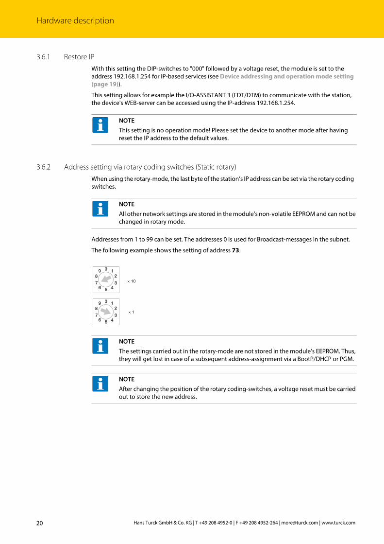
3.6.2 Address setting via rotary coding switches (Static rotary)When using the rotary-mode, the last byte of the station’s IP address can be set via the rotary coding switches.
Addresses from 1 to 99 can be set. The addresses 0 is used for Broadcast-messages in the subnet.
The following example shows the setting of address 73.
NOTEThis setting is no operation mode! Please set the device to another mode after having reset the IP address to the default values.
NOTEAll other network settings are stored in the module’s non-volatile EEPROM and can not be changed in rotary mode.
NOTEThe settings carried out in the rotary-mode are not stored in the module’s EEPROM. Thus, they will get lost in case of a subsequent address-assignment via a BootP/DHCP or PGM.
NOTEAfter changing the position of the rotary coding-switches, a voltage reset must be carried out to store the new address.
× 10
× 1
12
3456
7
89 0
12
3456
7
89 0
Hans Turck GmbH & Co. KG | T +49 208 4952-0 | F +49 208 4952-264 | [email protected] | www.turck.com20

Prog
ram
mab
le G
atew
ays B
Lxx-
PG-E
N-V
3
3.6.3 Address setting via the mode DHCPIn order to activate the DHCP-mode, the DIP-switch MODE is set to "ON", the rotary switches to address "40" (see Device addressing and operation mode setting (page 19)).
Address setting is carried out by a DHCP-server in the network after the start-up of the gateway.
The IP address, as well as the default subnet mask assigned to the gateway by the DHCP-server, are stored in the module’s EEPROM. If the gateway is subsequently switched to another address--mode, the settings (IP address, subnet mask, etc) will be read from the module’s EEPROM.
DHCP supports three mechanisms for IP address allocation:
In "automatic allocation", the DHCP-server assigns a permanent IP address to a client.
In "dynamic allocation", DHCP assigns an IP address to a client for a limited period of time. After this time, or until the client explicitly relinquishes the address, the address can be re-assigned.
In "manual allocation", a client's IP address is assigned by the network administrator, and DHCP is used simply to convey the assigned address to the client.
DHCP in PROFINET
Please assure, that in PROFINET-applications, the address assigned via a BootP-server corresponds to the address, which is assigned in the configuration tool.
3.6.4 Address setting via the mode PGM
In order to activate the PGM-mode, the DIP-switch MODE is set to "ON", the rotary switches to address "50" (see Device addressing and operation mode setting (page 19)).
The PGM-mode enables access of the software I/O-ASSISTANT (FDT/DTM) to the module’s network settings (see also „Address setting via DTM“).
NOTEAfter every change of the address-mode, a voltage reset must be done.
NOTEAfter every change of the address-mode, a voltage reset must be done.
NOTEIn the PGM-mode, all network settings (IP address, subnet mask, etc.) are read from the module’s internal EEPROM.
21V01.0| 2016/04

Hardware description
3.6.5 Address setting via the mode PGM-DHCP (universal mode)In order to activate the PGM-DHCP-mode, the DIP-switch MODE is set to "ON", the rotary switches to address "60" (see Device addressing and operation mode setting (page 19)).
The device sends DHCP-requests until an IP address is assigned (DHCP-server, PROFINET-controller, PACTware™, web server, IP-Address Tool).
The assigned IP-address is stored to the device and the DHCP-client is stopped.
Even after a restart of the device, the device sends no further DHCP-requests.
PGM-DHCP in PROFINET
This mode assures a PROFINET-compliant operation of the modules.
NOTEAfter every change of the address-mode, a voltage reset must be done.
NOTEIf a DHCP-server is used within the network, problems may occur during IP-assignment.
In this case, both, the DHCP-server as well as the PROFINET-controller (via DCP), try an IP-address-assignment.
Hans Turck GmbH & Co. KG | T +49 208 4952-0 | F +49 208 4952-264 | [email protected] | www.turck.com22

Prog
ram
mab
le G
atew
ays B
Lxx-
PG-E
N-V
3
3.6.6 F_Reset (Reset to factory setting)In order to reset the device to factory settings, the DIP-switch MODE is set to "ON", the rotary switches to address "90" (see Device addressing and operation mode setting (page 19)).
This mode sets all device-settings back to the default values and deletes all data in the device's inter-nal flash.
The following properties are reset to default or deleted during F_Reset:
NOTEThis setting is no operation mode! Please set the device to another mode after having reset the IP address to the default values.
Default value Comment
IP address/subnet mask
Reset 192.168.1.254/255.255.255.0
The device can be accessed by the web server/DTM using this IP address but the address is not permanently stored in the device.
PROFINET device name Reset -
CODESYS program deleted -
parameters (PG-V3) Reset see Parame-ters (page 39)
Parameters of I/O-modules
no
NOTEResetting the device to factory settings via DCP-based services (via Turck IP Address Tool or TIA-Portal/Step7) does not delete the CODESYS-program (see also Reset to factory set-tings (page 29).
23V01.0| 2016/04

Hardware description
3.6.7 Address setting with Turck IP Address ToolThe Turck IP Address Tool enables direct access to the Ethernet-network via the Ethernet cable.
The IP configuration, as well as the PROFINET device name of the Ethernet device can be changed application specifically.
Search for devices
Scan the network using the "Search" button. All found Turck devices are shown.
Send WINK command
For clear device localization a Wink command can be send to the marked device using the "Wink" button. The device responds to this Wink command with a device specific blink code (see LED dis-plays (page 31)).
Fig. 9: Scan Ethernet network
Fig. 10: Send WINK command
Hans Turck GmbH & Co. KG | T +49 208 4952-0 | F +49 208 4952-264 | [email protected] | www.turck.com24

Prog
ram
mab
le G
atew
ays B
Lxx-
PG-E
N-V
3
Changing the IP address
Use the function "Change IP configuration" to change the device's IP settings.
Changing the PROFINET device name
Use the function "Change device name" to change the device's IP settings.
Fig. 11: Changing the IP configuration
Fig. 12: Set PROFINET device name
NOTEA PROFINET device name can only be assigned, if the device has already been configured as PROFINET device via CODEYS and if the respective CODESYSproject has been loaded to the device (see chapterl 5, PROFINET-Device (page 51)).
25V01.0| 2016/04

Hardware description
3.6.8 Address setting via DTMThe software-tool I/O-ASSISTANT 3 (FDT/DTM) enables direct access to the Ethernet-network via the Ethernet cable.
The IP address, as well as the subnet mask of the TURCK Ethernet stations, can be changed accord-ingto the application by using the Busaddress Management function of the BL Service Ethernet interface (TCP/IP) in the software I/O-ASSISTANT 3 (FDT/DTM).
Fig. 13: Busaddress management
Hans Turck GmbH & Co. KG | T +49 208 4952-0 | F +49 208 4952-264 | [email protected] | www.turck.com26

Prog
ram
mab
le G
atew
ays B
Lxx-
PG-E
N-V
3
Fig. 14: Searching for network nodes in the Busaddress Management
NOTEThe access of the DTM to the station is only possible, if the station already has an IP-address (see Device addressing and operation mode setting (page 19))and if it is operated in switch position PGM or PGM-DHCP-mode.
NOTEWhen using Windows XP as operating system, difficulties may occur with system-inte-grated firewall.
It may inhibit the access of PACTware™ (I/O-ASSISTANT V3) to the Ethernet-network. In this case, please adapt your firewall respectively or deactivate it.
27V01.0| 2016/04

Hardware description
3.7 SET button
Pressing the SET button activates the write access of the device's USB Host port functions, see also chapterl 6, USB Host port functions (page 61).
Fig. 15: Changing the IP address
Fig. 16: SET button at BL20-PG-EN-V3 Fig. 17: SET button at BL20-PG-EN-V3
0 123
456789
0 123
456789
x10
x1
0987
6 5 432
1
0987
6 5 432
1
Hans Turck GmbH & Co. KG | T +49 208 4952-0 | F +49 208 4952-264 | [email protected] | www.turck.com28

Prog
ram
mab
le G
atew
ays B
Lxx-
PG-E
N-V
3
3.8 Reset to factory settings
Besides the hardware rest using the rotary coding switches (seeF_Reset (Reset to factory setting) (page 23)), the TURCK IP Address Tool as well as the web server (see Reset to Factory Defaults (page 74)) offer the possibility to reset the devices to the factory settings.
3.8.1 IP Address Tool
NOTEResetting the device to factory settings via rotary coding/DIP switchesdeletes the CODE-SYS-program in the device, see also F_Reset (Reset to factory setting) (page 23).Resetting the device to factory settings via DCP-based services (via Turck IP Address Tool or TIA-Portal/Step7) does not delete the CODESYS-program (see also F_Reset (Reset to factory setting) (page 23).
r
Fig. 18: IP Address Tool, reset to factory settings
29V01.0| 2016/04
Hardware description
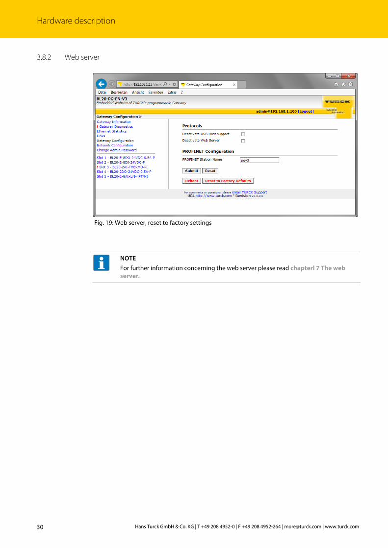
3.8.2 Web server
Fig. 19: Web server, reset to factory settings
NOTEFor further information concerning the web server please read chapterl 7 The web server.
Hans Turck GmbH & Co. KG | T +49 208 4952-0 | F +49 208 4952-264 | [email protected] | www.turck.com30

Prog
ram
mab
le G
atew
ays B
Lxx-
PG-E
N-V
3
3.9 LED displays
Every BLxx-PF V3 displays the following statuses via LEDs:
PLC status (LED RUN),
application specific LED APPL (freely programmable via CODESYS)
supply voltage (LED VI/VO, BL67 only),
common errors (LED ERR) and
Bus errors (LED BUS)
2 LEDs for the Ethernet-communication LNK1 and LNK2
3.9.1 LED description BL20
LED GREEN RED Meaning RemedyGW OFF OFF No power supply of the CPU. – Check the system power supply at the gateway.
ON OFF Firmware active, gateway readyOFF blinking Wink-command received – Wink-command received
LED GREEN RED Meaning RemedyIOs off OFF No power supply of the CPU. – Check the system power supply at the gateway.
ON OFF Communication running. The modules configured corre-spond to the modules in the sta-tion.
blinking, 1 Hz
OFF Station is in the Force Mode of the I/O-ASSISTANT.
– Deactivate the Force Mode of the I/O-ASSISTANT.
OFF ON CPU not ready for operation, possible causes:
– too many modules at the gate-way
– short-circuit in connected mod-ule
– gateway hardware error.
– Check the system power supply at the gateway and the cabling.
– Unmount excessively mounted modules.– Replace the gateway, if necessary.
OFF blinking, 1 Hz
Non adaptable changes in the con-figuration of the module bus nodes.
– Compare the configured station and the current configuration.
– Check the physical station for defective or incor-rectly plugged electronic modules.
OFF blinking, 4 Hz
no communicationvia the module bus.
– At least one module has to be plugged and has to be able to communicate with the gateway.
blinking, alternating The current and configured mod-ule list do not match but the data exchange proceeds as normal.
– Check the physical station for pulled or new but not planned modules.
– Check the system power supply at the gateway.OFF blinking
double 1 Hz
Device internal communication disturbed
LED GREEN RED MeaningAPPL This LED is controlled by the CODESYS program and can be freely programmed by the user.
31V01.0| 2016/04

Hardware description
LED GREEN RED Meaning RemedyRUN OFF OFF No power supply of the CPU. – Check the system power supply at the gateway.
ON OFF PLC program runningblinking OFF Firmware updated running see Firmware updateOFF ON PLC program stoppedOFF blinking No PLC program loadedOFF blinking,
1 HzF_Reset is in progress see page 23
LED GREEN RED Meaning RemedyBUS OFF OFF No power supply of the CPU. – Check the system power supply at the gateway.
ON OFF Displays the logical connection to a masterIf more than one slave is config-ured at the PG, then the LED shows the state of the slave in CODESYS which was the first to be config-ured.
blinking OFF Device ready for operationOFF ON Gateway error:
– IP address conflict– gateway in RESTORE-mode– F_Reset activated
– Check the IP-addresses in the network– Check the DIP switch position.
blinking, alternating – Auto-negotiation and/or
– Autonegotiation and / or waiting for DHCP- / BootP-address assign-ment.
– The gateway waits for IP-address assignment. Wait for the address assignment to be finished.
LED GREEN YELLOW Meaning RemedyLNKx OFF OFF no link – Check the Ethernet connection.
OFF ON Link established,10 Mbpsoff blinking Ethernet Traffic, 10 MbpsON OFF Link established,100 Mbpsblinking OFF Ethernet Traffic, 100 Mbps
LED GREEN RED Meaning RemedyERR OFF OFF Station running, no diagnostics
OFF ON A diagnostic message from gate-way or I/O-modules is pending.
– Check the diagnostic messages.
Hans Turck GmbH & Co. KG | T +49 208 4952-0 | F +49 208 4952-264 | [email protected] | www.turck.com32

Prog
ram
mab
le G
atew
ays B
Lxx-
PG-E
N-V
3
3.9.2 LED description BL67
LED GREEN RED Meaning RemedyIO OFF OFF No power supply of the CPU. – Check the system power supply at the gateway.
ON OFF Communication running. The modules configured corre-spond to the modules in the sta-tion.
blinking, 1 Hz
OFF Station is in the Force Mode of the I/O-ASSISTANT.
– Deactivate the Force Mode of the I/O-ASSISTANT.
OFF ON CPU not ready for operation, possible causes: too many modules at the gateway short-circuit in connected modulegateway hardware error.
– Check the system power supply at the gateway and the cabling.
– Unmount excessively mounted modules.– Replace the gateway, if necessary.
OFF blinking, 1 Hz
Non adaptable changes in the con-figuration of the module bus nodes.
– Compare the configured station and the current configuration.
– Check the physical BL67-station for defective or incorrectly plugged electronic modules.
OFF blinking, 4 Hz
no communicationvia the module bus.
– At least one module has to be plugged and has to be able to communicate with the gateway.
blinking, alternating The current and configured mod-ule list do not match but the data exchange proceeds as normal.
– Check the physical station for pulled or new but not planned modules.
– Check the system power supply at the gateway.OFF blinking
double 1 Hz
Device internal communication disturbed
LED GREEN RED Meaning RemedyGW OFF OFF No power supply of the CPU. – Check the system power supply at the gateway.
ON OFF Firmware active, gateway readyOFF blinking Wink-command received – Deactivate an active WINK-command
LED GREEN RED Meaning RemedyRUN OFF OFF No power supply of the CPU. Check the system power supply at the gateway.
ON OFF PLC program running -blinking OFF Firmware updated running see Firmware updateOFF ON PLC program stoppedOFF blinking No PLC program loadedOFF blinking,
1 HzF_Reset is in progress see page 23
LED GREEN RED Meaning RemedyVI/VO OFF OFF Supply voltage too low – Check the system power supply at the
gateway.ON OFF VI and VO within the nominal rangeblinking, 1 Hz
OFF Undervoltage VI; system running. – Check the system power supply at the gateway.
blinking, 4 Hz
OFF Undervoltage VO; system running.
ON(orange)
ON Sensor supply current (ISENS) too high
LED GREEN RED MeaningAPPL This LED is controlled by the CODESYS program and can be freely programmed by the user.
33V01.0| 2016/04

Hardware description
LED GREEN RED Meaning RemedyERR OFF OFF Station running, no diagnostics
OFF ON A diagnostic message from gateway or I/O-modules is pending.
– Check the diagnostic messages.
LED GREEN RED Meaning RemedyBUS OFF OFF No power supply of the CPU. – Check the system power supply at the
gateway.ON OFF Displays the logical connection to a master
If more than one slaves are configured at the PG, then the LED shows the state of the slave in CODESYS which was the first to be configured.
blinking OFF Device ready for operationOFF ON Gateway error:
– IP address conflict– gateway in RESTORE-mode– F_Reset activated
– Check the IP-addresses in the network– Check the DIP switch position.
blinking, alternating – Auto-negotiation and/or
– Autonegotiation and / or waiting for DHCP- / BootP-address assignment.
– The gateway waits for IP-address assign-ment. Wait for the address assignment to be finished.
LED GREEN YELLOW Meaning RemedyLNKx OFF OFF no link – Check the Ethernet connection.
OFF ON Link established,10 Mbpsoff blinking Ethernet traffic, 10 MbpsON OFF Link established,100 Mbpsblinking OFF Ethernet traffic, 100 Mbps
Hans Turck GmbH & Co. KG | T +49 208 4952-0 | F +49 208 4952-264 | [email protected] | www.turck.com34

Prog
ram
mab
le G
atew
ays B
Lxx-
PG-E
N-V
3
3.10 Real time clock (RTC)
Properties:
The RTC is set in the device for example using the CODESYS library „CAA Real time Clock Extern“.
Buffering via Gold CAP
Loading time for 95 % load min. 10 minutes
Buffer time at
23 °C 4 weeks
– 60 °C 168 hours
– 70 °C 36 hours
Fig. 20: CAA Real time Clock Extern in CODESYS
35V01.0| 2016/04

Hardware description
3.11 SFTP access
The SFTP access is done via a FTP client program e.g. FileZilla:
Server (SFTP protocol) IP address of the device
User name sftpuser
Password password
Port 22
NOTEThe password for the SFTP access is synchronized to the password for the web server. Changing the password for the SFTP access also changes the web server password (see page 71).
Fig. 21: SFTP access via FileZilla
Hans Turck GmbH & Co. KG | T +49 208 4952-0 | F +49 208 4952-264 | [email protected] | www.turck.com36

Prog
ram
mab
le G
atew
ays B
Lxx-
PG-E
N-V
3
3.12 Firmware update
The firmware update can be done using a USB storage device at the USB Host port or via the Turck DTM in PACTware™.
3.12.1 Firmware update using USB storage deviceFor the firmware update via USB storage device, please read section Functions of the USB Host port (page 61).
3.12.2 Firmware update via DTMThe firmware update via DTM is done in the DTM Busaddress Management in PACTware™.
Fig. 22: Busaddress Management in PACTware™
37V01.0| 2016/04

Hardware description
Hans Turck GmbH & Co. KG | T +49 208 4952-0 | F +49 208 4952-264 | [email protected] | www.turck.com38

Prog
ram
mab
le G
atew
ays B
Lxx-
PG-E
N-V
3
4 Parameters and diagnostics
4.1 Parameters
The BLxx-PG-EN-V3 provides the following parameters.
A Default setting
NOTEParameter changes are only applied after a device restart.
Parameter name Value Description
Deactivate WEB server no A
yes Deactivates the web server in the device.
Deactivate USB Hostsupport
no A
yes Deactivates the USB Host port support for the device. The USB Host port functions are deacti-vated.
Ethernet port 1/2 Auto-negotiation A Sets the Ethernet port to Auto-negotiation or to a fixed value for transmission rate and transmission mode.
10 Mbps, half duplex
10 Mbps, full duplex
100 Mbps, half duplex
100 Mbps, full duplex
39V01.0| 2016/04

Parameters and diagnostics
4.2 Diagnostics
4.2.1 System diagnosticsThe system diagnostics can be called via the instance name of the "Local_IO_BLxx"-object. Function blocks or libraries are not required.
Fig. 23: Diagnostics via call of instance
Diagnostics MeaningModule diagnostics available„xModuleDiagnosticsAvailable“
At least one module sends diag-nostics.
Check the diagnostic messages.
I/O configuration deviation„xI/OConfigurationDeviation“
I/O module list adaptable modi-fied, e. g., module has been pulled.
The current and configured module list do not match but the data exchange pro-ceeds as normal.
– Check the physical station for pulled or new but not planned modules.
– Check the system power supply at the gateway.
Module bus error „xModuleBusError“
The Communication with the module bus station on the module bus is not possible.
– At least one module has to be plugged and has to be able to communicate with the gateway.
I/O configuration error „xMasterOrIOConfigurationError“
The actual module list has been changed and is incompatible, a process data exchange with the module bus nodes is not possible-
– Compare the configured station and the current configuration.
– Check the physical station for defective or incorrectly plugged electronic mod-ules.
Hans Turck GmbH & Co. KG | T +49 208 4952-0 | F +49 208 4952-264 | [email protected] | www.turck.com40

Prog
ram
mab
le G
atew
ays B
Lxx-
PG-E
N-V
3
4.2.2 I/O diagnosticsThe diagnostics of the local I/O modules are available as process data in the modules' I/O mapping in CODESYS.
Undervoltage Usys„xUndervoltageUsys“
The load or system voltage are out of the permissible range.
Check the system power supply at the gateway.
Undervoltage at UL„xUndervoltageFieldSupply_Ul“Overloadsys„xOverloadIsys“
Overload at the system supply.
Fig. 24: I/O-module diagnostics in the process image.
Diagnostics Meaning
41V01.0| 2016/04

Parameters and diagnostics
Hans Turck GmbH & Co. KG | T +49 208 4952-0 | F +49 208 4952-264 | [email protected] | www.turck.com42

Prog
ram
mab
le G
atew
ays B
Lxx-
PG-E
N-V
3
5 CODESYS-functions The CODESYS 3 programmable multiprotocol gateways BL20-PG-EN-V3 and BL67-PG-EN-V3 can be used as follows:
5.1 Supported CODESYS libraries
Protocol Master Slave
Modbus TCP ✔ page 46 ✔ page 49
PROFINET - ✔ page 51
EtherNet/IP™ - ✔ page 56
3S libraries
Network – SysSocket, 3.5.6.0 (System)
Data access – SysFile, 3.5.6.0 (System)– SysFileAsync, 3.5.5.0 (System)– SysDir, 3.5.6.0 (System)
Time and date – SysTime, 3.5.5.0 (System)– SysTimeCore, 3.5.5.0 (System)– SysTimer, 3.5.5.0 (System)– SysTimeRtc, 3.5.5.0 (System)
Miscellaneous – SysEvent, 3.5.5.0 (System)– SysMem, 3.5.5.0 (System)
CAA libraries
Network – CAA Net Base Services, 3.5.6.0
Data access – CAA File, 3.5.6.0
Time and date – CAA DTUtil Extern, 3.5.5.0 – CAA Real Time Clock Extern, 3.5.5.40 – CAA Tick Extern, 3.5.5.0 – CAA TickUtil Extern, 3.5.5.0 – CAA Timer Extern, 3.5.5.0
Miscellaneous – CAA Mathematics, 3.5.1.0 – CAA Memory, 3.5.5.0
43V01.0| 2016/04

CODESYS-functions
5.2 General start-up
5.2.1 Installing the device package in CODESYS Download the package „BLxx-PG-EN-V3 CODESYS Package Vx.x.x.x“ from www.turck.com
Install the package using the CODESYS Package Manager „Tools Package Manager“.
The device package for CODESYS contains all necessary files
CODESYS Device Description,
CODESYS libraries,
GSDML file,
EDS file,
etc.
Fig. 25: Package Manager in CODESYS
Hans Turck GmbH & Co. KG | T +49 208 4952-0 | F +49 208 4952-264 | [email protected] | www.turck.com44

Prog
ram
mab
le G
atew
ays B
Lxx-
PG-E
N-V
3
5.2.2 Standard project with BLxx-PG-EN-V3 in CODESYS V3.5.8.10 Create a standard project with the BLxx-PG-EN-V3 as CODESYS device.
The CODESYS project is created.
In addition to the PLC logic, the project contains:
Gateway LED APPL
– for free use in the program
– uses 2 bit in the device's output process image, the output data therefore start with an offset of 1 byte in the default configuration.
Local_IO_BLxx
– Configuration of the I/O modules locally connected to the BLxx-PG-EN-V3
Ethernet interface
– Interface for the Modbus master or the Ethernet slaves
Fig. 26: Selecting the PG-V3 as CODESYS device
Fig. 27: CODESYS project
NOTEThe Ethernet interface needs no configuration.
45V01.0| 2016/04

CODESYS-functions
5.3 Modbus TCP-Master
5.3.1 Configuring the Modbus TCP-MasterThe Modbus TCP master from 3S - Smart Software Solutions GmbH is used.
Properties
max. number of TCP slaves 32
Min. Cycle Time 50 ms
Fig. 28: Add Modbus TCP-Master
Hans Turck GmbH & Co. KG | T +49 208 4952-0 | F +49 208 4952-264 | [email protected] | www.turck.com46

Prog
ram
mab
le G
atew
ays B
Lxx-
PG-E
N-V
3
Activate the function "auto-reconnect" at the master to assure that CODESYS automatically con-firms communication errors and tries to continue with executing Modbus commands instead of interrupting the Modbus communication.Otherwise the error has to be reset using a slave function block.
5.3.2 Configuring the external Modbus TCP slave Add an external Modbus TCP slave using the "Add Device" function and configure the slave.
In this example the Turck multiprotocol device TBEN-S1-4DIP-4DOP is used as Modbus slave.
Fig. 29: Configuring the Modbus TCP-Master
Fig. 30: Configuring the external Modbus TCP slave
47V01.0| 2016/04

CODESYS-functions
Add Modbus Slave channels for the communication with the slave.
Observe the process data offsets of the slave. In the example (Fig. 31: Adding Modbus Slave channels) the slave's process output data start with register 0x0800.
Fig. 31: Adding Modbus Slave channels
Hans Turck GmbH & Co. KG | T +49 208 4952-0 | F +49 208 4952-264 | [email protected] | www.turck.com48

Prog
ram
mab
le G
atew
ays B
Lxx-
PG-E
N-V
3
5.4 Modbus TCP-Slave-Device
5.4.1 Configuring Modbus TCP-Slave-Device Add the Modbus_TCP_Slave_Device to the Ethernet interface using the "Add Device"-function
and configure it.
Therefore define the number of in- and output registers (input and holding registers) which have to be exchanged with the higher-level Modbus TCP-master.
Properties
Max. number of input registers 1024
Max. number of holding registers 1024
Fig. 32: Configuring Modbus TCP-Slave-Device
49V01.0| 2016/04

CODESYS-functions
Which data will be mapped into the input and holding registers, depends on assignments in the PLC program or in the I/O mapping of the PG-V3 or of the local I/Os.
Fig. 33: Modbus TCP-Slave-Device data mapping
Hans Turck GmbH & Co. KG | T +49 208 4952-0 | F +49 208 4952-264 | [email protected] | www.turck.com50

Prog
ram
mab
le G
atew
ays B
Lxx-
PG-E
N-V
3
5.5 PROFINET-Device
5.5.1 Configuring the PROFINET-device in CODESYS Add the PROFINET_Device to the Ethernet interface using the "Add Device"-function and config-
ure the length ofthe in- and output data, which have to be exchanged with the higher-level PROF-INET-master.
Properties
max. number of I/O data 1024 byte in total(512 IN + 512 OUT)
NOTEIt can be necessary to increase the PROFINET cycle time for larger BLxx-stations.
Fig. 34: Configuring the PROFINET-device in CODESYS
NOTEWhen configuring the I/O-data the following has to be observed: The input data in CODE-SYS have to be configured as output data in the PROFINET-master configuration and the output data in CODESYS as input data.The data thus have to be configured in reverse order in the PROFINET-master configura-tion ( see also Configuring the in- and output data (page 55)).
51V01.0| 2016/04

CODESYS-functions
Which data will be mapped into the configured input and output data, depends on assignments in the PLC program or in the I/O mapping of the PG-V3 or of the local I/Os.
Fig. 35: PROFINET-device data mapping
NOTEThe PROFINET-device shows an error as long as a connection to the PROFINET-master is established.
Hans Turck GmbH & Co. KG | T +49 208 4952-0 | F +49 208 4952-264 | [email protected] | www.turck.com52

Prog
ram
mab
le G
atew
ays B
Lxx-
PG-E
N-V
3
5.5.2 Configuring the PROFINET-device in the PROFINET-masterThe following example shows the PROFINET-device configuration in TIA-Portal V13 from Siemens.
The PROFINET-CODESYS-device is configured as standard PROFINET-slave in TIA-Portal.
Hardware in the example:
PLC: S7 CPU315-2 PN/DP, 315-2EH13-0AB0
BL20-PG-EN-V3, FW 1.0.5.0
Installing the GSDML-file
Install the device's GSDML-file (GSDML-V2.3-TURCK-CDS3_PN_Device--.xml) in the PROF-INET configuration software. It can be downloaded fromwww.turck.com
The device is added to the hardware catalog „CDS 3 PN Device“.
Fig. 36: Configuring the PROFINET-device in TIA-Portal
53V01.0| 2016/04

CODESYS-functions
Configuring the PROFINET-parameters
Like for all other PROFINET-slave, the PROFINET-interface has to be configured for the CDS3 PN-Device“ in the project.
Set all necessary IP-settings and assign a PROFINET-device name or use the device name which has already been assigned to the device.
Fig. 37: Settings PROFINET-interface (CDS3 PN Device)
Hans Turck GmbH & Co. KG | T +49 208 4952-0 | F +49 208 4952-264 | [email protected] | www.turck.com54

Prog
ram
mab
le G
atew
ays B
Lxx-
PG-E
N-V
3
Configuring the in- and output data
Configure the in- and output data, which have to be exchanged with the CODESYS-device.
NOTEThe configuration of the data in TIA-Portal has to be done in reverse order compared to the configuration in CODESYS. Input data in TIA-Portal are output-data in CODESYS, and vice versa. The configured data lengths have to match.
Fig. 38: Configuration of in- and output data in TIA-Portal/CODESYS
55V01.0| 2016/04

CODESYS-functions
5.6 EtherNet/IP™ Slave (Device)
5.6.1 Configuring the EtherNet/IP™-device in CODESYS Add the Ethernet_IP_Slave to the Ethernet interface using the "Add Device"-function and con-
figure the length of the in- and output data, which have to be exchanged with the higher-level EtherNet/IP™-PLC.
Properties
max. number of I/O data 496 Byte IN492 Byte OUT
Fig. 39: Configuring the Ethernet/IP™-slave
Hans Turck GmbH & Co. KG | T +49 208 4952-0 | F +49 208 4952-264 | [email protected] | www.turck.com56

Prog
ram
mab
le G
atew
ays B
Lxx-
PG-E
N-V
3
Which data will be mapped into the configured input and output data, depends on assignments in the PLC program or in the I/O mapping of the PG-V3 or of the local I/Os.
Fig. 40: EtherNet/IP™-slave data mapping
57V01.0| 2016/04

CODESYS-functions
5.6.2 Configuring the EtherNet/IP™-slave in EtherNet/IP™ PLCThe following example describes the configuration of the EtherNet/IP™-slave in "RSLogix5000" V20.1. from Rockwell Automation.
The EtherNet/IP™-slave is configured as standard EtherNet/IP™-slave (Communications Adapter) in RSLogix.
Hardware in the example:
Controller. Logix 5572™ (Allen Bradley)
EtherNet/IP™-Bridge 1756EN2TR (Allen Bradley)
BL20-PG-EN-V3, FW 1.0.5.0
Installing the EDS-file
Install the device's EDS-file (Turck CDS3.eds) in the configuration software. It can be downloaded from www.turck.com
The device is added to the device catalog in RSLogix as „CDS 3 Ethernet/IP Slave“.
Fig. 41: "CDS 3 Ethernet/IP Slave" in the device catalog in RSLogix5000
Hans Turck GmbH & Co. KG | T +49 208 4952-0 | F +49 208 4952-264 | [email protected] | www.turck.com58

Prog
ram
mab
le G
atew
ays B
Lxx-
PG-E
N-V
3
Slave configuration
Enter the device name and the device's IP address.
Fig. 42: Settings at the "CDS3 Ethernet/IP Slave"
59V01.0| 2016/04

CODESYS-functions
Configuring the in- and output data
The device is automaticallyconfigured with a data width of 256 byte in- and 256 byte output data.
Configuring the in- and output data which have to be exchange with the CODESYS-device is thus not necessary. The Controller Tags are automatically generated.
Fig. 43: EtherNet/IP™-Connection "CDS3 Ethernet/IP Slave"
Fig. 44: Automatically generated Controller Tags of the "CDS3 Ethernet/IP Slave"
Hans Turck GmbH & Co. KG | T +49 208 4952-0 | F +49 208 4952-264 | [email protected] | www.turck.com60

Prog
ram
mab
le G
atew
ays B
Lxx-
PG-E
N-V
3
6 USB Host port functionsThe USB Host port serves for connecting USB storage devices for the storage, restore and transfer of CODESYS applications as well as for updating the device firmware.
6.1 Compatible storage devices
The USB Host port is generally suitable to connect commercially available USB storage devices.
Depending on the current consumption of the devices, compatibility problems may occur in iso-lated cases.
In order to guarantee error-free operation, we recommend to use industrially tested storage devices. Ident-Nr. 6827348 - USB 2.0 Industrial Memory Stick.
6.2 Functions of the USB Host port
For further information, see Function overview (page 63).
Read access The read access does not require a user intervention. The CODESYS program continues to run.
– BACKUP_1: Storing the CODESYS application on the storage device
– BACKUP_2: Storing the CODESYS application and further device data on the storage device
– USB_DATA: Storing of CODESYS recipes and/or log-fileson the storage device.
Write accessThe write requires user intervention (press the SET-button for at least 3 seconds). The CODESYS program is stopped.
– RESTORE_1: Loading the CODESYS application from the storage device to the device.
– RESTORE_2: Loading the CODESYS application and further device from the storage device to the device.
– USB_DATA_WRITE: Loading of CODESYS recipes and/or log-files from the storage device to the device
– FW_UPDATE
NOTEThe USB Host function can be deactivated using the web-server of the CODESYS program (bit 14 of the device parameter object).
NOTEOnly use USB memory sticks formatted to FAT or FAT32. The use of memory sticks format-ted to NFTS is not possible.
NOTEConnecting other USB devices like for example hard disks, keyboards, computer mouses etc. is not possible.
61V01.0| 2016/04

USB Host port functions
6.2.1 General hints/prerequisites The storage device is formatted in FAT (FAT or FAT32).
The storage device does contain only one folder. If the storage device contains more than one folder, not function is executed. TheRUN-LED displays errors, see Behavior of the RUN-LED in case of an error (page 66).
The folder name defines the function to be executed (for further information, see Function over-view (page 63).
Folder names must not contain special characters.
Boot application:The names of the CODESYS-application and the file names of the boot application (*.app and *.crc) have to be identical and must not be renamed.
Read access:Press the SET-button within 30 seconds after having plugged the storage device. If not, the func-tion is not executed an the storage device is unmounted.
NOTEThe storage device must not be plugged during normal operation. A restart or reset of the device with the storage device being plugged can destroy the running application.
NOTEUnplug the storage device only if the RUN-LED flashes orange (read/write operation fin-ished) or red/green (error).
Hans Turck GmbH & Co. KG | T +49 208 4952-0 | F +49 208 4952-264 | [email protected] | www.turck.com62

Prog
ram
mab
le G
atew
ays B
Lxx-
PG-E
N-V
3
6.2.2 Function overview
ATTENTION!Using CODESYS recipesCorrupt data due to manipulation of data in USB_Data file directory Only use 1:1-copies with Backup_2/Restore_2 when using recipes:
Function Folder name Description CODESYS-program
autom. devicerestart
Read accessBackup 1 BACKUP_1 Storing the CODESYS application on the storage device.
The following files are stored to the storage device.– All *.app and *.crc files. – PlcLogic folder
Existing files with the same name will be overwritten. All other data remain unchanged.
RUN NO
Backup 2 BACKUP_2 Storing the CODESYS application and the device data on from the BLxx-PG-EN-V3 on the storage device. The following files are stored to the storage device.
– All *.app and *.crc files. – PlcLogic folder– Folder USB_Data– IP address– PROFINET device name– Retain-data (retain.bin)
Existing files with the same name will be overwritten. All other data remain unchanged.
RUN NO
Read user data USB_DATA Storing the folder "USB_Data"from the BLxx-PG-EN-V3 to the stor-age device. The following files are stored to the storage device.
– CODESYS recipes and/or Log files Existing files with the same name will be overwritten. All other data remain unchanged.
RUN NO
Write accessRestore 1 RESTORE_1 Loading the CODESYS application from the storage device into
the device. The following files are loaded from the storage device to the device:
– All *.app and *.crc files. – PlcLogic folder
The folder must contain only one application file (*.app).All other applications on the device are deleted without further warnings.The device automatically executes a restart after unplugging the storage device.
STOP YES
63V01.0| 2016/04

USB Host port functions
Restore 2 RESTORE_2 Loading the CODESYS application and further device from the storage device into the BLxx-PG-EN-V3.The following files are loaded from the storage device:
– All *.app and *.crc files. – PlcLogic folder– Folder USB_Data– IP address– PROFINET device name– Retain-data (retain.bin)
The folder must contain only one application file (*.app).All other applications on the device except for the retain data are deleted without further warnings. The reatin data will only be overwritten if the storage device contains a newer file. The device automatically executes a restart after unplugging the storage device.
STOP YES
Firmware update FW_UPDATE Update of the device firmware. The IP address, the PROFINET device name and the CODESYS application will not be overwrit-ten. File name: BLxx-PG-EN_1234567_Vx.y.z.0.bin The device automatically executes a restart after unplugging the storage device.
STOP YES
Write user data USB_DATA_WRITE
Loading the folder "USB_Data"from the storage device into the device.Existing files with the same name will be overwritten. All other data remain unchanged.
STOP YES
Function Folder name Description CODESYS-program
autom. devicerestart
Hans Turck GmbH & Co. KG | T +49 208 4952-0 | F +49 208 4952-264 | [email protected] | www.turck.com64

Prog
ram
mab
le G
atew
ays B
Lxx-
PG-E
N-V
3
6.2.3 Executing the functionsBACKUP_1/BACKUP_2
Plug the storage device into the USB Host port.
The RUN-LED flashes with 4 Hz.
The backup is executed.
The RUN-LED flashes orange with 1 Hz.
The backup is completed.
Unplug the storage device.
USB_DATA
Plug the storage device into the USB Host port.
The RUN-LED flashes with 2 Hz.
The data are stored to the storage device.
The RUN-LED flashes orange with 1 Hz.
The storing is completed.
Unplug the storage device.
RESTORE_1/RESTORE_2
Plug the storage device into the USB Host port.
The RUN-LED flashes with 0.5 Hz.
Press the SET-button within the next 30 seconds for at least 3 seconds.
The RUN-LED flashes in the following order 2x green - pause (1 Hz) - 2 x green- pause (1 Hz) - .
Loading of data is executed.
The RUN-LED flashes orange with 1 Hz. The loading is completed.
Unplug the storage device.
The device is automatically restarted.
FW_UPDATE
Plug the storage device into the USB Host port.
The RUN-LED flashes with 0.5 Hz.
Press the SET-button within the next 30 seconds for at least 3 seconds.
The RUN-LED flashes in the following order 3x green - pause (1 Hz) - 3 x green- pause (1 Hz) - .
Loading of data is executed.
The RUN-LED flashes orange with 1 Hz. The firmware update is completed.
Unplug the storage device.
The device is automatically restarted.
65V01.0| 2016/04

USB Host port functions
USB_DATA_WRITE
Plug the storage device into the USB Host port.
The RUN-LED flashes with 0.5 Hz.
Press the SET-button within the next 30 seconds for at least 3 seconds.
The RUN-LED flashes with 2 Hz. The data are stored to the BLxx-PG-EN-V3.
The RUN-LED flashes orange with 1 Hz. The storing is completed.
Unplug the storage device.
The device is automatically restarted.
6.2.4 Behavior of the RUN-LED in case of an error
Error Description LED behaviorTimeout – The SET-button has not been pressed within the 30 seconds
after the plugging of the storage device.Red/green flashing (1 Hz)
Invalid folder – The storage device contains one folder with an invalid folder name.
– The storage device contains several folders with valid folder names.
Empty folder – The storage device contains one valid , but empty folder.USB deacti-vated
– The USB Host function has been deactivated using vie web-server or CODESYS program.
Red/green flashing (0.5 Hz)
Hans Turck GmbH & Co. KG | T +49 208 4952-0 | F +49 208 4952-264 | [email protected] | www.turck.com66
Prog
ram
mab
le G
atew
ays B
Lxx-
PG-E
N-V
3
7 The web server
7.1 Web server - remote access/configuration
7.2 Safety in the web server
In the web server, a default-password is assigned to the Turck devices for the administrator access.
We strongly recommend to use an individual password, in order to avoid possible misuse by a third party!
This should be done in the context of the network security concept for the complete facility in which the modules are placed.
7.3 IP address
In the delivery status, neither an address nor a PROFINET name is stored in the devices.
In order to be able to access the device via web server, the web server can be opened using the IP address 192.168.1.254.
If the PC used for the configuration is situated in the same IP network, page
http://192.168.1.254
can be opened in order to initially change some settings.
NOTEPlease change the password as described in Change Admin Password (page 71).
NOTEThe password is transfered as plain text.
67V01.0| 2016/04

The web server
7.4 Home
The web server's start page shows general device information, network settings, etc.
The „PLC Information“ part contains information concerning the CODESYS program status.
The menu items "Station Diagnostics", "Ethernet Statistics" and "Links" can also be accessed read-only without an administrator access.
Fig. 45: Start page of the web server of BL20-PG-EN-V3
Hans Turck GmbH & Co. KG | T +49 208 4952-0 | F +49 208 4952-264 | [email protected] | www.turck.com68

Prog
ram
mab
le G
atew
ays B
Lxx-
PG-E
N-V
3
7.5 Gateway Diagnostics
Diagnostic messages of the device are displayed on the "Station Diagnostics"-page.
Fig. 46: Diagnostics in the web server
69V01.0| 2016/04

The web server
7.6 Ethernet Statistics
The page "Ethernet Statistics" shows information like the port-status, telegram and error counters etc. The page can above all be useful for analyzing network problems.
7.7 Links
This page contains for example a link to the product page on the TURCK-homepage.
Fig. 47: Ethernet Statistics
NOTEThe "Ethernet summarized statistics" contain the statistics for both Ethernet ports.
Hans Turck GmbH & Co. KG | T +49 208 4952-0 | F +49 208 4952-264 | [email protected] | www.turck.com70

Prog
ram
mab
le G
atew
ays B
Lxx-
PG-E
N-V
3
7.8 Login/password
In order to obtain administrator rights and thus full access to the extended functions of the web server (Network Configuration, Station Configuration, etc.), you have to log-on to the web server as administrator.
For the first login use the default password "password".
The default-password should be be changed by the administrator. To do so, please follow the instructions under Change Admin Password (page 71).
7.9 Change Admin Password
Please define an individual password for administrator rights.
Default password: „password“
NOTEExecuting the „Reset to Factory Defaults“ also resets the password to "password“.
Fig. 48: Web server „password“
NOTEFor security aspects when working with the web server, please observe the notes under Safety in the web server (page 67).
NOTEThe password for the web server is synchronized to the password for the SFTP access. Changing the web server password also changes the see password for the SFTP access (page page 36).
NOTEExecuting the „Reset to Factory Defaults“ (see also Reset to Factory Defaults (page 74)) also resets the password to "password“.
71V01.0| 2016/04

The web server
Change password
Change the password for the station in the web server.
Write the changes into the device via "Submit".
Restart the device (voltage reset or pressing the set-button).
The device has accepted the new settings, the settings have become active.
Fig. 49: Change Admin Password
NOTE"Reset" only resets the changes done in the web server mask back to the original values. The function does not influence the device itself.
Hans Turck GmbH & Co. KG | T +49 208 4952-0 | F +49 208 4952-264 | [email protected] | www.turck.com72

Prog
ram
mab
le G
atew
ays B
Lxx-
PG-E
N-V
3
7.10 Network Configuration
On the "Network Configuration"-page, network-relevant settings can be changed.
7.10.1 Change network parameters (port settings, IP address, etc.)The device's network settings can be changed under "Network Configuration" only by users having administrator rights.
Change network parameters
Change the network parameters in the web server.
Write the changes into the device via "Submit".
The device has accepted the new settings, the settings have become active.
NOTEThe access of the web server to the station is only possible, if the station already has an IP address, Device addressing and operation mode setting (page 19).After a reset to factory settings, the device can be accessed using the IP address 192.168.1.254. This IP address is not stored permanently in the device.
If the device is set to "ROTARY" mode (Address setting via rotary coding switches (Static rotary) (page 20)), than the last byte of the IP address can not be changed via the web server.
Fig. 50: Web server with Network Configuration
NOTE"Reset" only resets the changes done in the web server mask back to the original values. The function does not influence the device itself.
73V01.0| 2016/04

The web server
7.11 Gateway Configuration
7.11.1 Configuration of the field bus interfaceThe "Gateway Configuration"-page serves for parameterizing the device's fieldbus interface:
Deactivating the USB Host port or the web server
Assigning a PROFINET device name
7.11.2 Reboot"Reboot" executes a power-cycle at the device.
7.11.3 Reset to Factory Defaults Resets the device to the default settings (factory settings), see also F_Reset (Reset to factory set-ting) (page 23).
Gateway Configuration
Change the configuration in the web server.
Write the changes into the device via "Submit".
The device has accepted the new settings, the settings have become active.
Fig. 51: Web server „Gateway Configuration“
NOTE"Reset" only resets the changes done in the web server mask back to the original values. The function does not influence the device itself.
Hans Turck GmbH & Co. KG | T +49 208 4952-0 | F +49 208 4952-264 | [email protected] | www.turck.com74

Prog
ram
mab
le G
atew
ays B
Lxx-
PG-E
N-V
3
7.12 Slot Parameters
7.12.1 Parameterization of the in-/ outputsThe "Parameters"-page is used to parameterize the module's I/O-channels.
Change parameters
Change the module parameters in the web server.
Write the changes into the device via "Submit".
Restart the device (voltage reset or pressing the set-button).
The device has accepted the new settings, the settings have become active.
NOTEParameter changes by the web server are valid in the device until the CODESYS program is downloaded to the device again, the device is restarted or parameters are changed in CODESYS by online change.
Fig. 52: Web server „Parameters“
NOTE"Reset" only resets the changes done in the web server mask back to the original values. The function does not influence the device itself.
75V01.0| 2016/04

The web server
7.13 Using mobile devices
The internal web server has a responsive design. This means, the web functions can also be exe-cuted using a mobile device, e.g. a smartphone.
The web content is automatically adapted to the smaller display in order to assure an optimized web server representation.
The Turck device and the mobile device have to be nodes of the same network. Please assure there-fore that the IP addresses of both devices are part of the same subnet (e.g. 255.255.255.0).
In addition to that, a WLAN access has to be available for the mobile device.
7.14 Web server logout
In order to disconnect a logged in user/PC with administrator rights from the web server, a logout is necessary.
If only the web browser is closed, the last active access is reactivated when opening the web server again from the same PC, which means, possibly with all administrator rights.
7.15 Deactivating the web server
Fig. 53: Access to the web server via smartphone
NOTEIf, for safety reasons, the web serves has to be deactivated completely, this is possible via the device parameters in CODESYS or in the web server itself (see page 74).If the web server is deactivated using the web server itself, further access to it is only pos-sible following a device reset to the factory settings (see page 74).
Hans Turck GmbH & Co. KG | T +49 208 4952-0 | F +49 208 4952-264 | [email protected] | www.turck.com76

...with 28 subsidiaries and over 60 representations worldwide!
www.turck.comD301373 | 2016/06
*D301373ßß1606*