bm 400 relay - mixed load, 4 contacts · the bm 400 relay is designed for both power levels and low...
TRANSCRIPT

www.morssmitt.com
1
BM 400 relay - Mixed load, 4 contactsDatasheet
DescriptionThe BM 400 relay has 3 silver double make / double break C/O contacts (form Z) and one gold bifurcated C/O contact
The plug-in design offers secure locking feature for maximum ease of maintenance (no wires need to be disconnected or other hardware removed for relay inspection or replacement).
The resistance to impact and vibration is conform to standards in force for Railway Transported Equipment. Positive mechanical keying of relay to socket is built into relay and socket during manufacture and terminal identifications are clearly marked on identification plate that is permanently attached to the relay.
The BM 400 relays is pluggable in the following sockets: EA 102 B, EA 102 BF, EA 103 BF, EA 104 B, EA 104 BF, EA 105 BF, EA 112 BF.
ApplicationThe BM 400 relay is designed for both power levels and low level signals are being switched for general purpose heavy duty applications such as lighting, pumps and fans, as standard weld no transfer design for safety critical applications such as door control, emergency brake failure, interlocking traction and breaking with a gold bifurcated contact for dry circuit signal information.
• Instantaneous relay• Plug-in design with secure locking feature
for maximum ease of maintenance• 3 double make / double break C/O silver
contacts (form Z)• 1 gold bifurcated C/O contact• Contact life (mechanical) of 100 million
cycles• -40 °C...+80 °C operating temperature• Contacts cross pollution barrier• Weld no transfer function for silver
contacts
• NF F 62-002 Rolling stock - Instantaneous relays contacts and sockets
• NF F16-101/102 Fire behaviour - Railway rolling stock
Features
Railway compliancy
• Proven reliable in heavy duty application• 3 silver contacts power contact and
1 gold bifurcated dry circuit contact• Long life cycle• Easy to maintain and replace• Low life cycle cost• No maintenance
Benefits
www.morssmitt.com
2
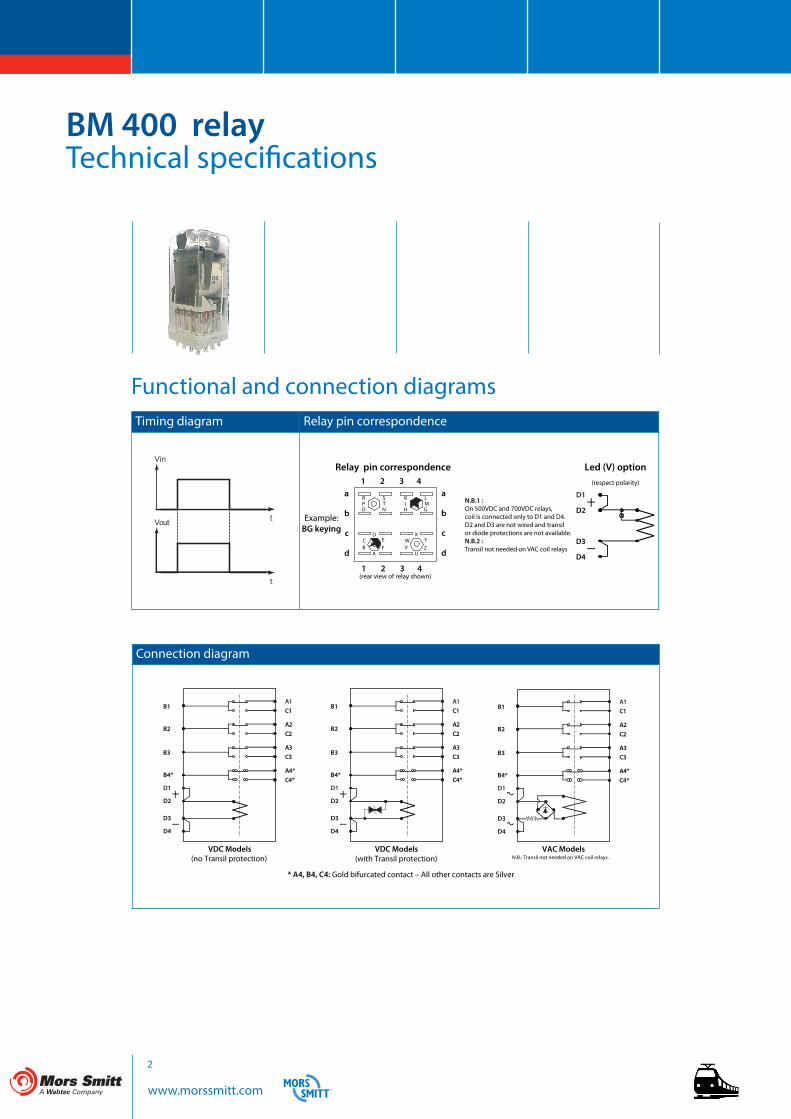
Timing diagram Relay pin correspondence
Functional and connection diagrams
BM 400 relayTechnical specifications
Connection diagram
a
b
c
d
1 2 3 4
Relay pin correspondence
(rear view of relay shown)
Example:BG keying
1 2 3 4
K
HJ
L
GM
S
NT
R
OP
DEF
CB
A
XYZ
WV
U
a
b
c
d
D1
D2
D3
D4
Led (V) option(respect polarity)
N.B.1 : On 500VDC and 700VDC relays, coil is connected only to D1 and D4.D2 and D3 are not wired and transil or diode protections are not available.N.B.2 : Transil not needed on VAC coil relays
VDC Models(no Transil protection)
* A4, B4, C4: Gold bifurcated contact – All other contacts are Silver
VDC Models(with Transil protection)
VAC ModelsN.B.: Transil not needed on VAC coil relays.
A1C1
A2C2
A3C3
A4*C4*
B1
B2
B3
B4*
D1
D2
D3
D4
A1C1
A2C2
A3C3
A4*C4*
B1
B2
B3
B4*
D1
D2
D3
D4
A1C1
A2C2
A3C3
A4*C4*
B1
B2
B3
B4*
D1
D2
D3
D4

www.morssmitt.com
3
Contact data - silver contacts
BM 400 relayTechnical specifications
Coil data - DC versions
(1) Coil resistance tol.: ± 8% at 20 °C (2) Valid for closed relay.
Keying Unom (VDC) Uoperating (VDC)
Pnom (W) Uhold (VDC) Udrop-out (VDC)
R coil (Ω) (1) L/R (ms) (2)
MEZ 12 8 / 16 3.5 6.25 1.25 40 40AGZ 24 16 / 33 3.5 13.5 2.5 170 40FLZ 36 25 / 45 3.5 21 3.5 390 40DGZ 48 33 / 60 3.5 28.5 4.5 625 40BGZ 72 48 / 90 3.5 40.5 6.5 1600 40USB 96 65 / 120 3.8 50 9 2400 40EGZ 115 77 / 144 3.5 60 11.5 4000 40FGZ 550 440 / 660 4 300 50 75500 40UTB 700 450 / 900 4.2 380 60 115000 40
Keying Unom (VAC) Uoperating (VAC)
Pnom (VA) Uhold (VAC) Udrop-out (VAC)
R coil (Ω) (1) L/R (ms) (2)
EMZ 127 88 / 143 4 71.5 12 4000 40CGZ 220 176 / 242 3 129 21 14350 40
Coil data - AC versions
(1) Coil resistance tol.: ± 8% at 20 °C (2) Valid for closed relay.
Nominal current 12 A resistiveNominal breaking capacity and life 3 A at 72 VDC L/R : 0 ms Electrical life: 5 x 10⁶ op.
1 A at 72 VDC L/R: 30 ms Electrical life: 2.5 x 10⁶ op.3 A at 220 VAC 50 Hz cosØ=1 Electrical life: 2.5 x 10⁶ op.Lamp filament circuit: 200 W at 72 VDC Electrical life: 5 x 10⁵ op.
Contact closure time Pick-up time N/O < 55 ms Drop-out* time N/C < 25 msContact opening time Pick-up time N/C < 50 ms Drop-out* time N/O < 15 msMinimum contact continuity 20 mA at 24 VDCNumber of contacts 3 double make / double break contacts (form Z)Contact material Hard silver overlay laminated to copperContact resistance initial 10 mΩ max at 5 A end of life 40 mΩ max at 5 A
www.morssmitt.com
4
BM 400 relayTechnical specifications
Electrical characteristicsDielectric strength 2000 VAC, 1 min between contacts
2600 VAC, 1 min between contacts, coil and frame
Insulation resistance > 1000 MΩ at 500 VDC
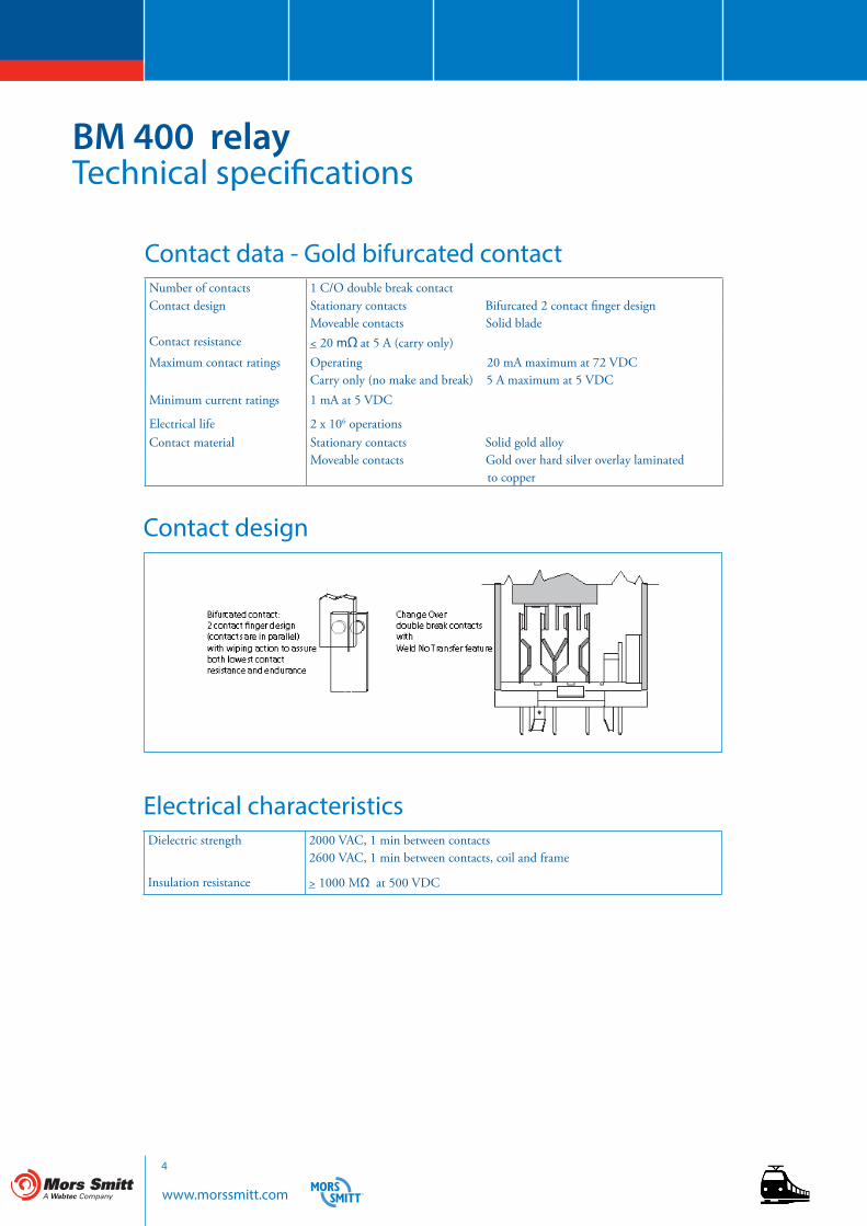
Contact design
Contact data - Gold bifurcated contactNumber of contacts 1 C/O double break contactContact design Stationary contacts Bifurcated 2 contact finger design
Moveable contacts Solid bladeContact resistance < 20 mΩ at 5 A (carry only)Maximum contact ratings Operating 20 mA maximum at 72 VDC
Carry only (no make and break) 5 A maximum at 5 VDCMinimum current ratings 1 mA at 5 VDC
Electrical life 2 x 10⁶ operationsContact material Stationary contacts Solid gold alloy
Moveable contacts Gold over hard silver overlay laminated to copper
www.morssmitt.com
5
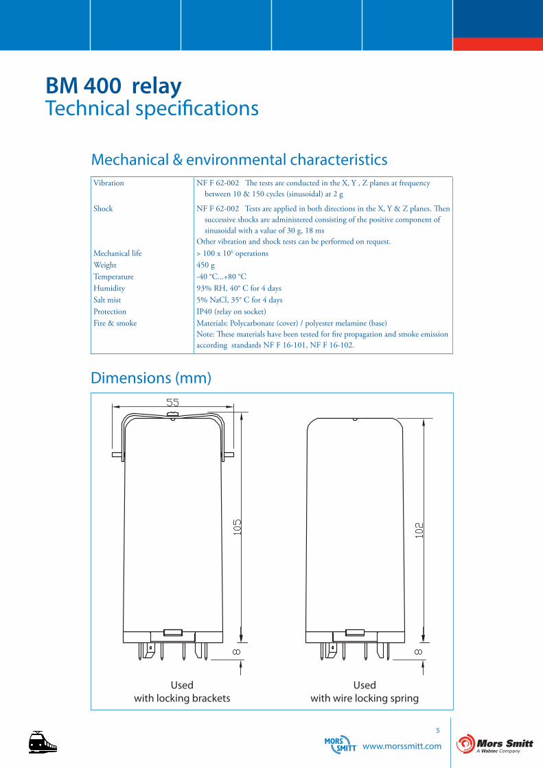
Dimensions (mm)
BM 400 relayTechnical specifications
Mechanical & environmental characteristicsVibration NF F 62-002 The tests are conducted in the X, Y , Z planes at frequency
between 10 & 150 cycles (sinusoidal) at 2 g
Shock NF F 62-002 Tests are applied in both directions in the X, Y & Z planes. Then successive shocks are administered consisting of the positive component of sinusoidal with a value of 30 g, 18 msOther vibration and shock tests can be performed on request.
Mechanical life > 100 x 106 operationsWeight 450 g Temperature -40 °C...+80 °CHumidity 93% RH, 40° C for 4 daysSalt mist 5% NaCl, 35° C for 4 daysProtection IP40 (relay on socket)Fire & smoke Materials: Polycarbonate (cover) / polyester melamine (base)
Note: These materials have been tested for fire propagation and smoke emission according standards NF F 16-101, NF F 16-102.
Usedwith locking brackets
Usedwith wire locking spring

www.morssmitt.com
6
BM 400 relayTechnical specifications
Dynamic relay selection curve No 1
(for silver contacts)
Curve 1 2 3 4
VAC 220 125 48 24
AC Current breaking capacity versus life expectancy in millions of cycles.Rate of contacts opening and closing = 1200 operations per hour.Curves shown for resistive load (Power Factor = 1).
Mill
ions
of C
ycle
s
Amps
1
0
30
5060
40
0,1
0,2
0,5
1
2,5
5
10
20
1 1,5 2 2,5 3 4 5 6 7 8 10 12
2
3
4
www.morssmitt.com
7
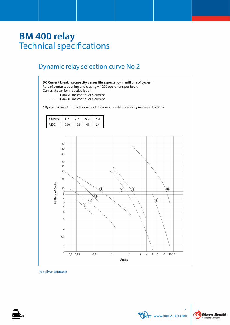
Dynamic relay selection curve No 2
BM 400 relayTechnical specifications
(for silver contacts)
L/R= 20 ms continuous currentL/R= 40 ms continuous current
* By connecting 2 contacts in series, DC current breaking capacity increases by 50 %
DC Current breaking capacity versus life expectancy in millions of cycles.Rate of contacts opening and closing = 1200 operations per hour.Curves shown for inductive load -
Curves 1-3 2-4 5-7 6-8
VDC 220 125 48 24
Mill
ions
of C
ycle
s
Amps
1
60
0,2 0,25 0,5 1 2 3 4 5 6 8 10 12
50
40
30
25
20
15
10987
6
5
4
3
2
1,5
1
0
2
3
4 5 6
7
8

www.morssmitt.com
8
BM 400 relayTechnical specifications
Dynamic relay selection curve No 3
(for silver contacts)
DC Current breaking capacity versus life expectancy in millions of cycles.Rate of contacts opening and closing = 1200 operations per hour.Curves shown for resistive load (L/R = 0). Continuous current.
Curve 1 2 3 4
VDC 220 125 48 24
Mill
ions
of C
ycle
s
Amps
1
0,2 0,25 0,5 1 2 3 4 5 6 8 10 12
60
50
40
30
25
20
15
10987
6
5
4
3
2
1,5
1
0
2
3
4
* By connecting 2 contacts in series, DC current breaking capacity increases by 50 %
www.morssmitt.com
9
BM 400 relayTechnical specifications
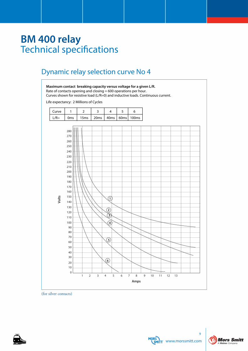
Dynamic relay selection curve No 4
(for silver contacts)
Maximum contact breaking capacity versus voltage for a given L/R.Rate of contacts opening and closing = 600 operations per hour.Curves shown for resistive load (L/R=0) and inductive loads. Continuous current.
Curve 1 2 3 4 5 6
L/R= 0ms 15ms 20ms 40ms 60ms 100ms
200
190
180
170
160
150
120
110
100
90
80
70
60
50
40
30
20
10
0
130
140
210
220
230
240
250
260
270
280
1 2 3 4 5 6 7 8 9 10 11 12 13
6
5
4
3
2
1
Amps
Volts
Life expectancy: 2 Millions of Cycles
www.morssmitt.com
10
BM 400 relayTechnical specifications
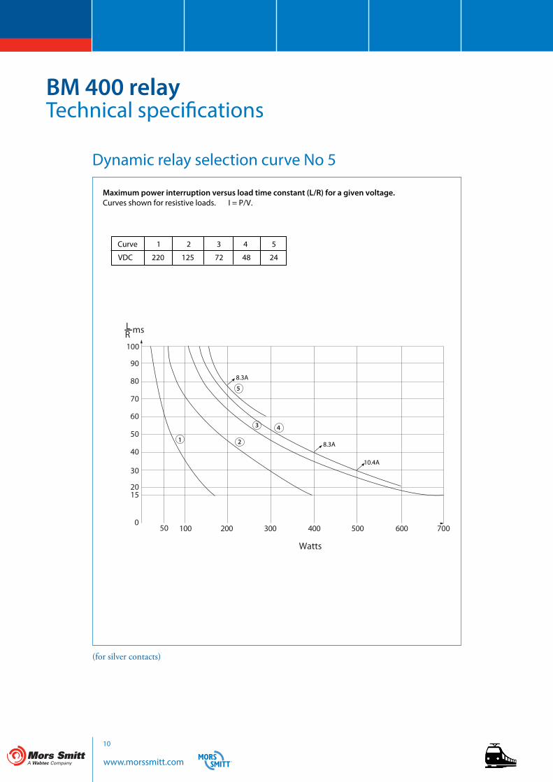
Dynamic relay selection curve No 5
(for silver contacts)
Maximum power interruption versus load time constant (L/R) for a given voltage.Curves shown for resistive loads. I = P/V.
Curve 1 2 3 4 5
VDC 220 125 72 48 24
50 005003002
4
21
006004001
100
90
80
70
60
50
40
30
2015
0
5
msLR
700
3
8.3A
8.3A
10.4A
Watts
www.morssmitt.com
11
BM 400 relayTechnical specifications
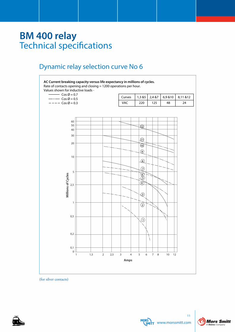
Dynamic relay selection curve No 6
(for silver contacts)
AC Current breaking capacity versus life expectancy in millions of cycles.Rate of contacts opening and closing = 1200 operations per hour.Values shown for inductive loads -
Cos Ø = 0.7Cos Ø = 0.5Cos Ø = 0.3
Curves 1,3 &5 2,4 &7 6,9 &10 8,11 &12
VAC 220 125 48 24
Mill
ions
of C
ycle
s
Amps
1 1,5 2 2,5 3 4 5 6 7 8 10 120
0,1
0,2
0,5
1
2,5
5
10
20
30
40
50 12
11
10
9
8
7
56
4
3
2
1
60
www.morssmitt.com
12
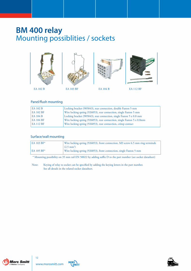
BM 400 relayMounting possiblities / sockets
EA 103 BF*
EA 105 BF*
Wire locking spring (926853), front connection, M3 screw 6.5 mm ring terminals (2,5 mm2)Wire locking spring (926853), front connection, single Faston 5 mm
Surface/wall mounting
EA 102 BEA 102 BFEA 104 BEA 104 BFEA 112 BF
Locking bracket (905843), rear connection, double Faston 5 mm Wire locking spring (926853), rear connection, single Faston 5 mm Locking bracket (905843), rear connection, single Faston 5 x 0.8 mmWire locking spring (926853), rear connection, single Faston 5 x 0.8mmWire locking spring (926853), rear connection, crimp contact
Panel/flush mounting
* Mounting possibility on 35 mm rail EN 50022 by adding suffix D to the part number (see socket datasheet)
Note: Keying of relay to socket can be specified by adding the keying letters in the part number. See all details in the related socket datasheet.
EA 102 B EA 103 BF EA 104 B EA 112 BF
www.morssmitt.com
13
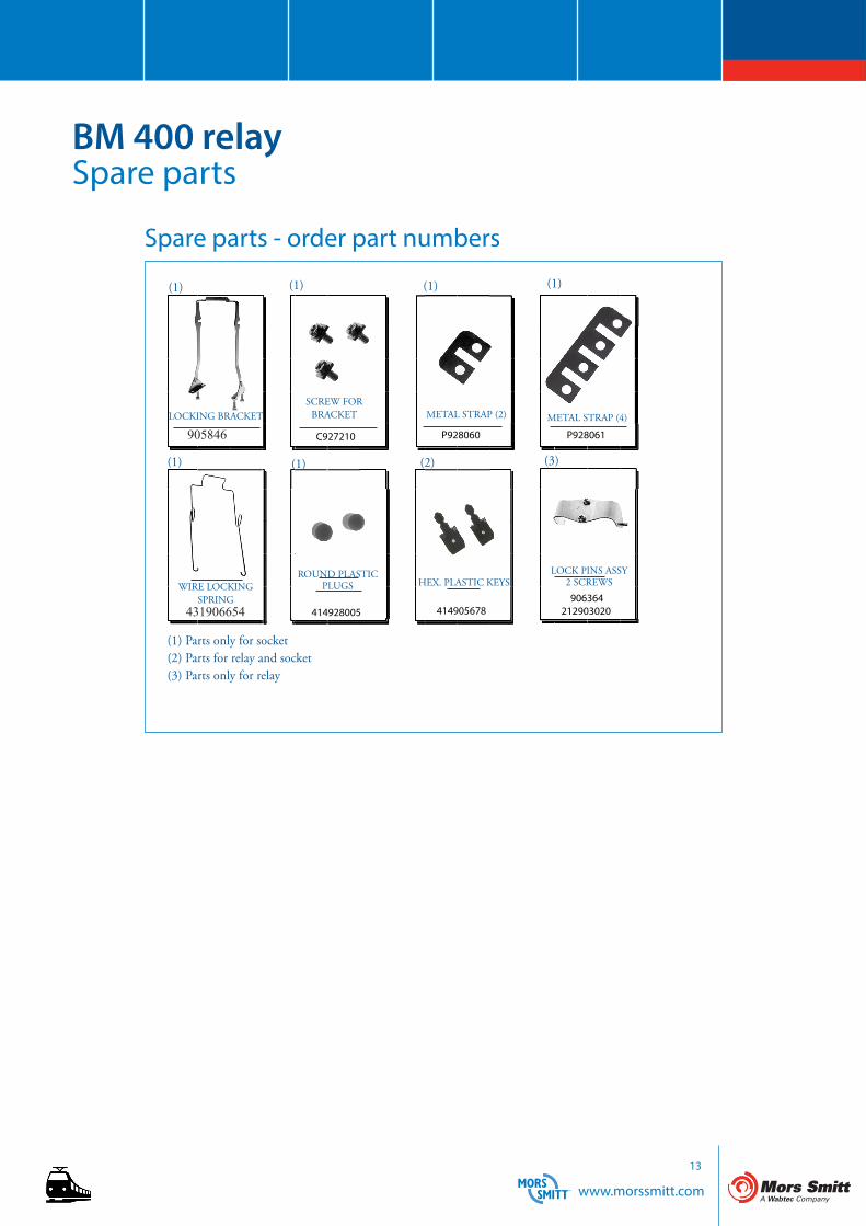
P928060C927210
414905678414928005906364
212903020
P928061905846
431906654
BM 400 relaySpare parts
Spare parts - order part numbers
SCREW FOR BRACKET METAL STRAP (2) METAL STRAP (4)
ROUND PLASTIC PLUGS HEX. PLASTIC KEYS
LOCK PINS ASSY2 SCREWS
(1) (1) (1) (1)
(1) (2) (3)
LOCKING BRACKET
WIRE LOCKING SPRING
905843
926853
(1)
(1) Parts only for socket(2) Parts for relay and socket(3) Parts only for relay
905846
431906654
www.morssmitt.com
14
BM 400 relayInstructions
Install socket and connect wiring correctly according identification to terminals. Plug relay into socket. Reverse installation into socket not possible due to mechanical blocking by snap-lock.Don’t reverse polarity of coil connection. Relays can be mounted (tightly) next to each other. and in any attitudeWarning! Never use silicon near by relays
Installation
Before operating always apply voltage to coil to check correct operation.Long term storage may corrode the silver on the relay pins. Just by plugging the relay into the socket, the female bifurcated receivers will automatically clean the corrosion on the pins and guarantee a good connection.Do not use the relay in places with flammable gas as the arc generated from switching could ignite gasses.
Operation
Correct operation of relay can easily be checked as transparent cover gives good visibility on the moving contacts. When the relay doesn’t seem to operate correct, please check presence of coil voltage. Use a multimeter.If LED is used, coil presence should be indicated. If coil voltage is present, but the relay doesn’t work, a short circuit of suppression diode is possible (The coil connection was reversed). If relay doesn’t work after inspection, please replace relay unit by a similar model. Send defective relay back to manufacturer. Normal wear and tear excluded.
Maintenance
www.morssmitt.com
15
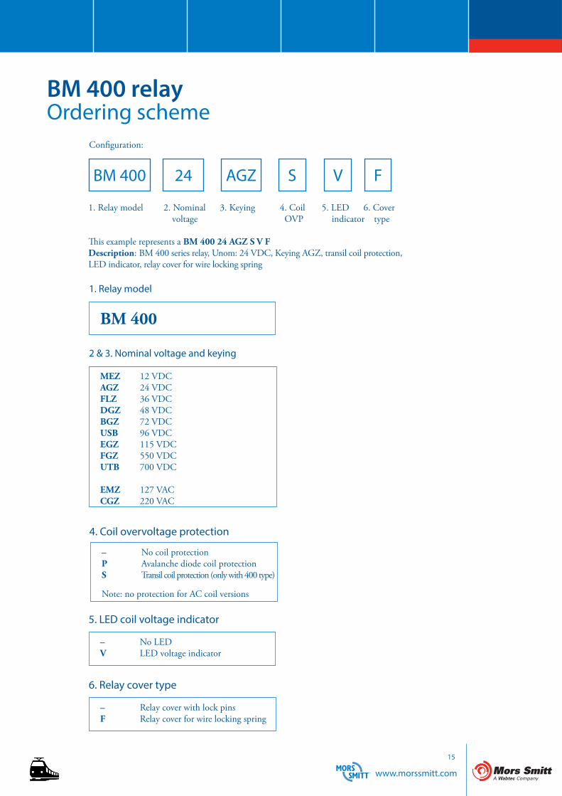
BM 400 relayOrdering scheme
Configuration:
BM 400 24 AGZ S F
BM 400
MEZ 12 VDCAGZ 24 VDCFLZ 36 VDCDGZ 48 VDCBGZ 72 VDCUSB 96 VDCEGZ 115 VDCFGZ 550 VDCUTB 700 VDC
EMZ 127 VACCGZ 220 VAC
This example represents a BM 400 24 AGZ S V FDescription: BM 400 series relay, Unom: 24 VDC, Keying AGZ, transil coil protection, LED indicator, relay cover for wire locking spring
1. Relay model
2 & 3. Nominal voltage and keying
1. Relay model 2. Nominal 3. Keying 4. Coil 5. LED 6. Cover voltage OVP indicator type
V
– No LEDV LED voltage indicator
– Relay cover with lock pinsF Relay cover for wire locking spring
4. Coil overvoltage protection
5. LED coil voltage indicator
6. Relay cover type
– No coil protectionP Avalanche diode coil protectionS Transil coil protection (only with 400 type)
Note: no protection for AC coil versions
www.morssmitt.com
Mors Smitt France SAS
Tour Rosny 2, Avenue du Général de Gaulle,
F - 93118 Rosny-sous-Bois Cedex, FRANCE
T +33 (0)1 4812 1440, F +33 (0)1 4855 9001
Mors Smitt Asia Ltd.
29/F., Fun Towers, 35 Hung To Road
Kwun Tong, Kowloon, HONG KONG SAR
T +852 2343 5555, F +852 2343 6555
Mors Smitt B.V.
Vrieslantlaan 6, 3526 AA Utrecht,
NETHERLANDS
T +31 (0)30 288 1311, F +31 (0)30 289 8816
Mors Smitt Technologies Inc.
1010 Johnson Drive,
Buffalo Grove, IL 60089-6918, USA
T +1 847 777 6497, F +1 847 520 2222
Mors Smitt UK Ltd.
Graycar Business Park, Barton under Needwood,
Burton on Trent, Staffordshire, DE13 8EN, UK
T +44 (0)1283 722650 F +44 (0)1283 722651
RMS Mors Smitt
6 Anzed Court, Mulgrave,
VIC 3170, AUSTRALIA
T +61 (0)3 8544 1200 F +61 (0)3 8544 1201
(c) Copyright 2016All rights reserved. Nothing from this edition may be multiplied, or made public in any form or manner, either electronically, mechanically, by photocopying, recording, or in any manner, without prior written consent from Mors Smitt. This also applies to accompanying drawings and diagrams. Due to a policy of continuous development Mors Smitt reserves the right to alter the equipment specification and description outlined in this datasheet without prior notice and no part of this publication shall be deemed to be part of any contract for the equipment unless specifically referred to as an inclusion within such contract. Mors Smitt does not warrant that any of the information contained herein is complete, accurate, free from potential errors, or fit for any particular purpose. Mors Smitt does not accept any responsibility arising from any party’s use of the information in this document.
DS-
BM 4
00 re
lay-
V2.
1 Ju
ly 2
016