bmea final report - george mason university · (bmea final report) prepared by: nat hall ... wider...
TRANSCRIPT
Biometrics Enterprise Architecture
Final Project Report (BMEA Final Report)
Prepared by:
Nat Hall Mike Luckey
Jeremy Worley
Date: December 18, 2009


Executive Summary
Biometrics is the science of establishing the identity of a person based on or his or her physical, chemical, or behavioral characteristics. It is a rapidly growing field with many applications. Some examples include verifying the identity of a person attempting to access a computer network, or someone conducting a transaction with an Automated Teller Machine (ATM). Furthermore, in modern society, the constant threat of terrorist attacks underscores the need for a reliable large scale biometric identity system capable of accommodating a large number of individuals.
The limitations associated with today’s large scale biometric systems are that they are generally inflexible and not optimized for use within an enterprise. Many biometric systems are procured based on their image capture and match algorithm capabilities, with little thought given as to how the system will fit into an organization’s existing system architecture, or how the biometric information will be used within a particular agency’s business process/structure. As a result, many biometric systems are developed in a stovepipe fashion with little or no interoperability with other biometric systems. Furthermore, proprietary vendor algorithms provide limited system flexibility.
Team Biometric Enterprise Architecture (BM EA) seeks to investigate the limitations associated with current biometric enterprise architecture implementations, and ultimately provide some alternative implementations that will generate improvements in system flexibility, interoperability, and performance.
Team BM EA followed a structured system engineering approach to developing and evaluating alternative architecture implementations. The team documented an “As-Is” biometric architecture implementation along with requirements for an alternative “To-Be” biometric architecture implementation. Team BM EA used a systems engineering modeling tool to capture the functions and data flows for the “To-Be” architecture implementation. The “To-Be” implementation will eliminate stovepipe, redundant components in line with our stakeholder requirements. Communication will reside on a common, standards-based, data portal, with more efficient and interoperable communication between elements within the architecture.
Through research into methods for accomplishing the stakeholders’ key goals of flexibility, interoperability, and open architecture, the team selected service-oriented communication architecture back by cloud computing “commodity” hardware. These technologies deployed with a flexible architecture to take full advantage of these technologies were shown through analysis and simulations to meet the key stakeholder goals as an effective cost point. The “To-Be” will allow for the flexible use of multiple vendor match algorithms, prioritization of transactions through the system, virtualization of servers to provide flexible hardware processing resources to meet immediate transaction needs, and the agile allocation and de-allocation of processing power to cost effectively meet surge needs during peak periods or during high threat conditions. This new architecture provides the advantage of better overall performance over a wider range of different transaction types and scenarios particularly under ever shifting workload, mission priorities, and budgets.
Team BMEA developed a performance model to compare the performance of two different types of implementations through a hypothetical border crossing application and to demonstrate how an engineer can take this new architecture and develop a flexible system optimized to a particular application.

Executive Summary
Based on initial results obtained from the performance model, Team BM-EA recommends that agencies/organizations attempting to introduce biometric enterprise architecture within their business construct implement Service Oriented Architecture (SOA) like technologies on cloud computing “commodity” hardware to improve system interoperability, flexibility, and performance at an improved price point. The team also explored the use of an agent-based model.
Furthermore, results from Team BM-EA’s cost modeling indicate that significant low-risk savings can be realized by switching from the As-Is implementation.
1
BIOMETRICS ENTERPRISE ARCHITECTURE TEAM BMEA
18 DECEMBER 2009
BIOMETRICS ENTERPRISE ARCHITECTURE
Table of Contents
1 Introduction ................................................................................................................................2
2 Background ................................................................................................................................2
2.1 Problem Statement ........................................................................................................... 2
2.2 Team Role ........................................................................................................................ 3
2.2.1 Nat Hall ..................................................................................................................... 4
2.2.2 Jeremy Worley .......................................................................................................... 4
2.2.3 Mike Luckey ............................................................................................................. 5
2.3 Customer/Stakeholder ...................................................................................................... 5
2.4 Mission Statement ............................................................................................................ 6
3 Project Definition .......................................................................................................................6
3.1 Scope ................................................................................................................................ 6
3.2 Project Assumptions/Limitations ..................................................................................... 6
3.3 Approach .......................................................................................................................... 6
3.3.1 Problem Formulation and Analysis .......................................................................... 6
3.4 Expected Results .............................................................................................................. 7
3.4.1 Technical Performance Model .................................................................................. 7
4 Stakeholder Analysis .................................................................................................................9
4.1 Identified Stakeholders ..................................................................................................... 9
4.1.1 Department of Homeland Security (DHS) .............................................................. 10
4.1.2 Federal Bureau of Investigation (FBI) .................................................................... 10
4.1.3 Department of State (DOS) ..................................................................................... 10
4.1.4 State and Local Law Enforcement Agencies .......................................................... 10
4.2 Stakeholder Needs/Wants Analysis ............................................................................... 10
4.2.1 Stakeholder Needs Analysis Matrix........................................................................ 10
4.3 IDEF0 ............................................................................................................................. 11
4.4 Functional Decomposition ............................................................................................. 12
4.4.1 Accept Requests and Provide Feedback ................................................................. 12
4.4.2 Assess Image Quality .............................................................................................. 13
4.4.3 Create Subject ID Record ....................................................................................... 13
4.4.4 Conduct Search For Matches .................................................................................. 13

2
BIOMETRICS ENTERPRISE ARCHITECTURE TEAM BMEA
18 DECEMBER 2009
BIOMETRICS ENTERPRISE ARCHITECTURE
4.4.5 Store Data................................................................................................................ 13
4.4.6 Conduct Performance Tests .................................................................................... 13
4.4.7 Perform Reviewer Functions .................................................................................. 13
5 Systems Engineering Methodology .........................................................................................13
5.1 Project Development Process ......................................................................................... 13
6 BMEA Context Diagram .........................................................................................................14
7 Architecture Evaluation ...........................................................................................................15
8 Technical Case .........................................................................................................................16
8.1 BM-EA Operational Concept ......................................................................................... 16
8.1.1 System Requirements Specification ....................................................................... 16
8.1.1.1 The Biometric Collection Component ............................................................. 17
8.1.1.2 The Requestor Component .............................................................................. 17
8.1.1.3 The Subject Component ................................................................................... 17
8.1.2 System Development Diagrams .............................................................................. 17
8.2 Technical Case ............................................................................................................... 18
8.2.1 Biometric Architecture Performance Simulation .................................................... 18
8.2.1.1 Hypothetical Application ................................................................................. 18
8.2.1.2 Model Components and Findings .................................................................... 18
8.3 Business Case ................................................................................................................. 20
8.3.1 Assumptions and NPV comparison of Base Case (As-Is) to Alternative (To-Be) . 24
8.4 Conclusion ...................................................................................................................... 29
Appendix A. References ..............................................................................................................1
References ........................................................................................................................................1
Appendix B. Biometric Architecture Performance Simulation ...................................................1
Appendix C. Function Point Analysis Values ...........................................................................23
Appendix D. BMEA Requirements Document .........................................................................31
Appendix E. Analysis of Alternatives (AOA) ...........................................................................40
Appendix F. System Description Document (SDD) ...................................................................1
Appendix G. Systems Engineering Management Plan (SEMP) ................................................92

1
BIOMETRICS ENTERPRISE ARCHITECTURE TEAM BMEA
18 DECEMBER 2009
BIOMETRICS ENTERPRISE ARCHITECTURE
List of Figures
Figure 1 BMEA Analysis Team ..................................................................................................... 4
Figure 2 Community Stakeholders ................................................................................................. 9
Figure 3 Stakeholder Value Mapping Identifies BMEA Priorities ............................................... 11
Figure 4 BMEA Functional Context IDEF0 Diagram .................................................................. 12
Figure 5 BMEA CONOPS/Context Diagram ............................................................................... 12
Figure 6 Team BMEA Systems Engineering Approach ............................................................... 14
Figure 7 As-Is Biometric Enterprise Architecture ........................................................................ 14
Figure 8 AOA Technology Curves ............................................................................................... 15
Figure 9 BMEA Operational Context ........................................................................................... 16
Figure 10 BM-EA External Systems Diagram ............................................................................. 17
Figure 11 Biometric Transaction Flow through our performance model ..................................... 19
Figure 12 Function Point Table Basis I ........................................................................................ 21
Figure 13 Function Point Table Basis II ....................................................................................... 21
Figure 14 As-Is Sales and Pricing Table....................................................................................... 22
Figure 15 As-Is Cash Flow Table ................................................................................................. 22
Figure 16 To-Be Sales and Pricing Table ..................................................................................... 23
Figure 17 To-Be Cash Flow Table ................................................................................................ 23
Figure 1 - Performance Simulation Process Flowchart - Hypothetical Border Application .......... 2
Figure 19 - Hardware, Reviewers, Border crossings and Visa Application Processing ................. 3
Figure 20 - Arena Animated Interface ............................................................................................ 6
Figure 21 - Arena Provides Major Queue Lengths ......................................................................... 8
Figure 22 - Main Simulation Module that Creates Required Distributions .................................... 9
Figure 23 - An example of one of the modules that traps and bins the transactions for the collection of statistics ...................................................................................................................... 9
Figure 24 - Manual Enrollment Module ....................................................................................... 10
Figure 25 – High-level Human Review Processing Flow ............................................................ 10
Figure 26 - High-level 2-stage match engine module ................................................................... 11
Figure 27 – Baseline run performance results. ............................................................................. 12
Figure 28 – Stress Test 1 ............................................................................................................... 13
Figure 29 - In stress test 2 ............................................................................................................. 14
Figure 30 - Adjusting staff levels higher after lower quality images ........................................... 15
2
BIOMETRICS ENTERPRISE ARCHITECTURE TEAM BMEA
18 DECEMBER 2009
BIOMETRICS ENTERPRISE ARCHITECTURE
Figure 31 - Stress test 3 – Surge hardware ................................................................................... 16
Figure 32 - Increase Nightshift Staff allowed ............................................................................... 16
Figure 33 - Further increased hardware 50% to bring response time down. ................................ 17
Figure 34 - SOA Architecture allow Alternative Stage 1 and Stage 2 Matchers ......................... 18
Figure 35 - Sudden increase in transactions by 50%. ................................................................... 18
Figure 36 - Priority Transactions .................................................................................................. 19
Figure 39 BM-EA Context Diagram............................................................................................. 33
Figure 40 BM EA Functional Decomposition Diagram ............................................................... 35

1
BIOMETRICS ENTERPRISE ARCHITECTURE TEAM BMEA
18 DECEMBER 2009
BIOMETRICS ENTERPRISE ARCHITECTURE
List of Tables
Table 1 Architecture Performance Summary Differences ............................................................ 20
Table 2 - Transaction Queues ......................................................................................................... 4
Table 3 - Transaction Queues ......................................................................................................... 5
Table 4 - Custom Event Counts Accumulated during 5 days (actual 10% scale) .......................... 7
Table 5 – Full Scale Transactions ................................................................................................. 20
Table 6 - Performance Summary Differences .............................................................................. 22

2
BIOMETRICS ENTERPRISE ARCHITECTURE TEAM BMEA
18 DECEMBER 2009
BIOMETRICS ENTERPRISE ARCHITECTURE
1 INTRODUCTION
Biometrics is the science of establishing the identity of a person based on his or her physical, chemical, or behavioral characteristics. It is a rapidly growing field with many applications that includes various and sundry applications. Some examples include a means to restrict access to a computer, the use of Automated Teller Machines (ATMs), and passage through airport security checkpoints. Today many commercial and government identity management systems employ biometric technologies to support their operations. Some use biometrics as a support service in their enterprise environment while others offer biometric services to companies and organizations that require biometric capabilities that cannot bear the biometric enterprise investment. Finally and predominately, the preponderance of biometric applications supports both the legal and security domains allowing those stakeholders the ability to assure successful identification within the given domain.
The most common biometric applications include the capture, display, search and assessment of fingerprints, facial features, iris scans, and voice traits of individuals for comparison to a reference scan population. The challenge, across an enterprise is to ensure that all biometric applications can interact and be fused into mutually supporting identities across the entire domain and those identities are efficiently compared to ad-hoc, randomly collected data points consisting of a subset of the reference data.
2 BACKGROUND
Biometric practitioners require acquisition of various biometric images from various biometric acquisition systems. Predominately, these systems are procured based on their image acquisition method rather than the purpose or circumstances for which the images are acquired or needed. As a result, vendors produce stovepipe systems that include solutions for requirements that do not exist from an image acquisition perspective.
Enterprise biometric practitioners do not have a reliable source for image management capabilities beyond purchasing or acquiring image acquisition capabilities (hardware) that happens to have its own, often proprietary image management software. As a result, biometric practitioners who have a need to integrate or use multiple biometric capabilities (such as coupling fingerprint, facial and voice recognition into an identity) end up with duplicative and non-interoperable image management software. They also end up with a significant interoperability dilemma when integrating operations with other agencies that are also faced with the same problem.
2.1 PROBLEM STATEMENT
Current biometric systems are generally inflexible and not optimized for use within an enterprise. Most biometric systems are monolithic, thick-client or standalone applications with very little ability to interface to enterprise management information systems (MISs). Many biometric applications do offer some interoperability and integration points with and for established MISs such as PeopleSoft, SAS, Oracle and the like for personnel and accountability functions. However, the ability of such enterprise systems to collaborate across a diverse set of biometric systems is limited because of the lack of standardization and enterprise architecture support amongst the various biometric systems. Likewise, there is a distinct lack of robust architectural

3
BIOMETRICS ENTERPRISE ARCHITECTURE TEAM BMEA
18 DECEMBER 2009
BIOMETRICS ENTERPRISE ARCHITECTURE
support within the security and legal domains when using biometrics in those business contexts evidenced by the significant investment in stovepipe biometric systems. This problem is widely recognized in the various biometric communities, including the public sector (i.e. government civilian agencies), as evidenced by the testimony of Mr. Rand Beers, the Under Secretary, National Protection and Programs Directorate, Department of Homeland Security to the United States Senate Committee on Homeland Security and Governmental Affairs when asked about Terrorist Travel1
Thus, the biometric market today is continuing a trend towards monopolistic stovepipe systems risking higher prices and less innovation. Small scale, open-source initiatives however demonstrate the opportunity for improving biometric system collaboration and performance through higher quality and modern architectural choices. Our intent with this project is to highlight alternatives for implementing biometric architecture for favorable consideration across an enterprise. This project could become the basis for goals to which an enterprise could subscribe when looking to improve their biometrics-business function capability sets. This could be considered whether an enterprise is updating or upgrading present, existing biometric infrastructure, or is considering a wholesale reconfiguring, re-architecting, or re-implementing of business functions supported by biometric identification capabilities.
The purpose of this project is to document and demonstrate the comparison and trade-off of current systems within their current architecture to like systems supported by a more robust and modern architecture.
2.2 TEAM ROLE
For this project, Team Biometrics Enterprise Architecture takes on the role of a Systems Engineering team with a goal of assessing current biometric systems’ architecture as evidenced by ad-hoc, de-facto implementations across various enterprises and comparing that de-facto implementation with a prospective, modern and architecturally robust implementation.
Our Project Management Plan (PMP) and our Systems Engineering Management Plan (SEMP) describe, in detail, our makeup, organization, and methods to arrive at the solution. Our team is working under the tutelage and mentorship of Dr. Thomas Speller as part of the SEOR 798/680 Systems Engineering and Operations Research Applied Project Course on behalf of the SEOR department within the Volgenau School of Information Technology and Engineering at George Mason University. The team is organized as shown in Figure 1 BMEA Analysis Team, and aims to provide a valid overall architectural alternative to that which is currently available for biometric systems when employed within an enterprise.
1 “Statement for the Record, by Rand Beers, Under Secretary, National Protection and Programs Directorate, Department of Homeland Security, Before the, United States Senate, Committee on Homeland Security and Governmental Affairs, Washington, D.C., Terrorist Travel, December 9, 2009.” (http://hsgac.senate.gov/public/index.cfm?FuseAction=Files.View&FileStore_id=16e8ac24-2fb2-4672-bf28-4c1e6f72113b)

4
BIOMETRICS ENTERPRISE ARCHITECTURE TEAM BMEA
18 DECEMBER 2009
BIOMETRICS ENTERPRISE ARCHITECTURE
Figure 1 BMEA Analysis Team
2.2.1 NAT HALL
Nat is enrolled in his final class in the George Mason University MSOR program. He has his BS in Electrical Engineering with a minor in Management from Rensselaer Polytechnic Institute. Nat is currently a Principal Engineer with Noblis, Inc. where he has worked for over 6 years. Nat has conducted research and evaluations on identity management solutions and infrastructure security protection in support of several Noblis clients including DoD, DHS/TSA, DHS/CBP, DHS/ S&T, DoS, DoT, NOAA, USCG, USPS, New Jersey State, and The Cleveland Clinic. Prior to his work in government consulting, Nat co-founded Herndon Web Service, Inc in 1994 developing database-oriented web sites and applications and then serving as its President from 1997 through 2001. Prior to 1994, Nat was self-employed from 1991 at F. I. Technology where he envisioned, developed, and marketed a software testing product to simulate factory processes and to emulate electronics for factory automation equipment. Prior to 1991, Nat was a Senior Systems Engineer managing the systems engineering department of Simmons Machine Tool Corporation, an OEM of automated factory equipment serving the railroad industry.
2.2.2 JEREMY WORLEY
Jeremy is enrolled in his final class in the George Mason University MSSE program. He specialized in the C4I track. Jeremy obtained a BS in Electrical Engineering Technology in May 2003 from Old Dominion University. Upon graduation, he began his career in 2004 with the United States Marine Corps as a DOD civilian employee under the Naval Acquisition Intern Program (NAIP). Jeremy was assigned to Marine Corps Systems Command (MCSC) in Quantico, VA and spent his first three years under the NAIP. During this time, Jeremy worked in the command’s C4I Interoperability Branch. Jeremy coordinated across multiple MCSC program offices to ensure that interoperability issues between individual C4I systems were addressed properly. The NAIP afforded Jeremy the opportunity to quickly gain knowledge of the DOD Acquisition Process through multiple Defense Acquisition University (DAU) courses and external assignments/rotations. In early 2006, Jeremy completed a four month external

5
BIOMETRICS ENTERPRISE ARCHITECTURE TEAM BMEA
18 DECEMBER 2009
BIOMETRICS ENTERPRISE ARCHITECTURE
rotation at Camp Pendleton, CA working in the Systems Architecture and Engineering Branch of the Marine Corps Tactical Systems Support Activity (MCTSSA). Upon graduation from the NAIP, Jeremy came on board full time with MCSC as a Systems Engineer. Jeremy currently works in the program office for Optics and Non-lethal systems (ONS). He serves as the team lead for ONS’s Electro-Optic Test Facility (EOTF). The EOTF is the program office’s in-house optics laboratory, used for the test and evaluation of optical scopes and night vision devices to support source selections and R&D initiatives. The EOTF is capable of performing a wide range of electro-optical tests for thermal sensors, image intensification devices, day scopes, and laser systems.
2.2.3 MIKE LUCKEY
Mike is enrolled in his final class in the George Mason University MSSE program. He specialized in the Computer Based Systems track, and has over 19 years of program management and systems engineering experience working for the Department of Defense. He has a BS in Business Finance from the University of Florida. As a DOD contractor he is the lead engineer and project manager working with the U. S. Army’s Logistics Innovation Agency working to modernize Army Logistics business processes and technologies. A retired U. S. Marine Corps Officer, Mike has deployed to Somalia and Okinawa Japan supporting USMC and DOD C4I activities in his role as a Data Communications Officer. Upon retiring, Mike has worked in various levels both with various DOD contractors and with the Defense Information Systems Agency (DISA) working a variety of systems engineering and project management areas. Mike’s experiences include requirements planning and analysis, system design and architectures, workflow analysis, scheduling, developmental and operational testing, risk management, configuration management, quality assurance, operations and sustainment, process improvement, and the like. Mike’s interests are primarily in engineering and implementation of technologies enabling and enhancing large-scale and enterprise systems.
2.3 CUSTOMER/STAKEHOLDER
Our customer is Noblis, Inc., a nonprofit science, technology and strategy organization that helps clients solve complex systems, process and infrastructure problems in ways that benefit the public. We have partnered with them through Mr. Nat Hall, who works at Noblis and has colleagues interested in engaging our team for architectural analysis of biometric systems.
Some of the relevant areas of interest are to identify architecture for next-generation large-scale government biometric systems identifying effective performance, cost, and flexibility tradeoffs and develop a guidance document for system design, system procurement, and performance testing of biometric systems.
Goals for next-generation systems include:
• Improved system performance such as maximizing “match accuracies” with set throughput and response time requirements.
• Search against very large image/identity repository(ies) –in the millions • Incentivize vendors to continually invest to improve match algorithm performance • Incentivize anti-monopoly and open-source algorithms • Support per search prioritization • Support flexible system scaling for rapidly changing threat levels

6
BIOMETRICS ENTERPRISE ARCHITECTURE TEAM BMEA
18 DECEMBER 2009
BIOMETRICS ENTERPRISE ARCHITECTURE
• Identify financially effective tradeoffs among system hardware/software, maintenance, testing, and match review (may assume a fixed sample acquisition process)
The resulting guidance document is to assume that precise weightings of goals will be application specific. Hypothetical examples may help illustrate how the guidance should be followed in practice.
These goals are part of our project this semester; there is no guarantee that we will be able to answer each and every one. We will however, at a minimum, set the stage for answering these requirements and will provide answers at the end where we are able, as we go through the process of documenting process technology and implementation of enterprise application of biometric capabilities.
2.4 MISSION STATEMENT
Team BMEA is chartered to investigate existing biometric implementations to assess barriers to biometric enterprise integration. Team BMEA will produce “As-Is” biometrics systems architecture along with technical and financial (economic) performance models and results and will compare them to prospective “To-Be” technical and financial (economic) models and results.
3 PROJECT DEFINITION
3.1 SCOPE
Team BMEA’s project provides results that serve to establish parameters for indicating non-vendor specific, non-proprietary flexible, scalable prospective biometric implementations within either an existing or prospective enterprise. Specifically Team BMEA:
• Investigated alternatives to biometric system enterprise integration barriers • Investigated alternatives for flexible, interoperable, scalable and open solutions • Provides a pattern for non-proprietary open-standard based access to vendor match and
search algorithms
3.2 PROJECT ASSUMPTIONS/LIMITATIONS
One limitation associated with our project is that an open standards based approach for vendor algorithms does not exist. A community approach for open interfaces for vendor search and match algorithm needs to be initiated.
3.3 APPROACH
Team BM-EA proceeded through literature research, project organization, problem formulation, problem space analysis, problems space requirements definition, solution space definition, solutions space design and development including model design, development, execution and results analysis. The remaining parts of this section describe, at a high level our implementation of this approach.
3.3.1 PROBLEM FORMULATION AND ANALYSIS
Team BM-EA used literature review to analyze key aspects of the problem statement; to uncover existing Biometric System Enterprise Architecture (EA) and how that EA is applied across the systems that employ it. Team BM-EA assessed the data processing and communications flows

7
BIOMETRICS ENTERPRISE ARCHITECTURE TEAM BMEA
18 DECEMBER 2009
BIOMETRICS ENTERPRISE ARCHITECTURE
required, how the various data algorithms were used to improve data flow, and ultimately developed a model that provides an analysis of best case response to chosen Biometric Assessment in our proposed EA.
The following literature was reviewed as a part of our Biometric Enterprise Architecture research efforts to include published papers, reports, trade journals, books, and other research materials. Research for this project falls mainly into three categories:
• Current Biometric System Architectures • Current Biometric Systems Implementation • Biometric Architecture Modeling and Simulation
Each is discussed briefly below:
Current Biometric System Architectures – Research in this category included investigating what architecture is in place supporting the various biometric capabilities and includes a look at if various architectures are mutually supporting.
Current Biometric Systems Implementation – Research in this category included investigating the various systems implemented within the various architectures to serve as a catalog for considering architectural trade-offs as Team BMEA assessed alternative architectures. Likewise, this catalog was used as a basis for documenting the existing and contemplated architecture.
Biometric Architecture Modeling and Simulation - The Biometric Enterprise Architecture project Team researched modeling and simulation methods and models, mining for algorithms and data types that allow for efficient and, where possible, optimal collection and data exchange of biometric data and information. Where adequate models exist we took advantage of them, where needed, to extend them and created our own, where we needed. With these models, the Team BMEA investigated technical and economic performance of existing biometric architecture and determined improvements resulting from the proposed architecture.
3.4 EXPECTED RESULTS
The expected result of this system is a proposed alternative architecture for enterprise-scale biometric systems. Below are the products that will be expected at the end of this study.
3.4.1 TECHNICAL PERFORMANCE MODEL
A technical performance model was developed to analyze the feasibility of the system as compared to existing implementations for similar capabilities. The artifacts captured in the architecture of the system were used by our queuing model to simulate the operational concept of this architecture. The result of the model is an analysis showing the various performance characteristics for resolving selected, various biometric enterprise business requirements. The Core® modeling tool was used to capture the architecture of the existing biometric architecture. A set of views or artifacts defined below were developed to present the architecture:
• Context Diagram: This diagram captures the high level operational concept of the biometric system and aids in the description and understanding of the boundary conditions.
• System Description Document: This document lists all operational nodes/stakeholders of the system, and also the information needed to be exchanged among these nodes. In this

8
BIOMETRICS ENTERPRISE ARCHITECTURE TEAM BMEA
18 DECEMBER 2009
BIOMETRICS ENTERPRISE ARCHITECTURE
architecture, for example, image acquisition nodes, image management nodes and image exchange nodes are captured along with all information exchanged among them. This view also captures the internal and external interfaces of this system. It will capture system interfaces and boundaries. It describes the system’s primary engineering elements in a structured manner for review of the physical and behavior of the resulting architecture. Key attributes and relationships are listed.2
• System Description Matrix: This view summarizes and expands the characteristics of the exchanged information captured in the System Description Document. The exchanged information’s attributes such as information content, classification, periodicity, criticality, and timeliness are included in this view.
• Functional Flow Block Diagram (FFBD): The FFBD shows the functions that a system is to perform and the order in which they are to be enabled (and performed). The order of performance is specified from the set of available control constructs .Control enablement is shown by reference node(s) which precede it, and reference node(s) at the end of function logic indicate what functions are enabled next. The FFBD also shows completion criterion for functions as needed for specification. The FFBD does not contain any information relating to the flow of data between functions, and therefore does not represent any data triggering of functions. The FFBD only presents the control sequencing for the functions3. This view depicts a high-level operational activity process of the system. It displays the high-level activities of image acquisition, management and resultant exchanges.
• N-2 Diagram (N2): The N2 Chart is structured by locating the functions on the diagonal, resulting in an N x N matrix for a set of N functions. For a given function, all outputs are located in the row of that function and all inputs are in the column of the function. If the functions are placed on the diagonal in the nominal order of execution, then data items located above the diagonal represent normal flow down of data. Data items below the diagonal represent data item feedback. External inputs can optionally be shown in the row above the first function on the diagonal, and external outputs can be shown in the right-hand column. If desired, data repositories can be represented by placing them on the diagonal with the functionsibid.
• Integrated Definition For Function Modeling (IDEF0): The IDEF0 Diagram represents the mechanism (usually the component to which the function is allocated) which performs the function. IDEF0 Diagram corresponds to Enhanced Functional Flow Block Diagrams (EFFBD) ibid.
• Enhanced Functional Flow Block Diagram (EFFBD): This view captures different scenarios/use cases of the operational concept. This view depicts the relative time-based information flow processes of the activities captured in the FFBD. The EFFBD displays the control dimension of the functional model in an FFBD format with a data flow
2 Systems Engineering Guided Tour, Vitech Corporation 2007. 3 Relationships between Common Graphical Representations in System Engineering Jim Long, http://www.vitechcorp.com/whitepapers/files/200701031634430.CommonGraphicalRepresentations_2002.pdf)

9
BIOMETRICS ENTERPRISE ARCHITECTURE TEAM BMEA
18 DECEMBER 2009
BIOMETRICS ENTERPRISE ARCHITECTURE
overlay to effectively capture data dependencies. Thus, the Enhanced FFBD represents: (1) functions, (2) control flows, and (3) data flows. The logic constructs allow you to indicate the control structure and sequencing relationships of all functions accomplished by the system being analyzed and specified. When displaying the data flow as an overlay on the control flow, the EFFBD graphically distinguishes between triggering and non-triggering data inputs. Triggering data is required before a function can begin execution. Therefore, triggers are actually data items with control implications. Non-triggering data inputs are shown with gray backgrounds and with single-headed arrows. The Enhanced FFBD specification of a system is complete enough that it is executable as a discrete event model, providing the capability of dynamic, as well as static, validation. A fundamental rule in the interpretation of an EFFBD specification is that a function must be enabled (by completion of the function(s) preceding it in the control construct) and triggered (if any data input to it is identified as a trigger) before it can execute ibid.
4 STAKEHOLDER ANALYSIS
Our stakeholders primarily consist of agencies that require biometric capabilities to support their internal business processes and need to expose portions of their business processes to their brother/sister organizations in resolving identity issues.
Many of these agencies collect and disseminate biometric information internally but are reluctant to invest in additional, needed biometric-sourced information, primarily because these organizations understand that similar (or the same) information is possessed, (but is unavailable) from the other/brother/sister organizations. These agencies include:
• Department of Homeland Security (DHS) • Department of Justice (DOJ/FBI) • State and Local Law Enforcement Agencies
4.1 IDENTIFIED STAKEHOLDERS
Figure 2 Community Stakeholders

10
BIOMETRICS ENTERPRISE ARCHITECTURE TEAM BMEA
18 DECEMBER 2009
BIOMETRICS ENTERPRISE ARCHITECTURE
4.1.1 DEPARTMENT OF HOMELAND SECURITY (DHS)
Department of Homeland Security (DHS) intends to employ biometric applications to screen potential U. S. border crossers entering and exiting the country. DHS also has plans to incorporate and fuse biometrics data with internally supported watch lists including “no-fly” lists and other protection oriented lists.
4.1.2 FEDERAL BUREAU OF INVESTIGATION (FBI)
The Federal Bureau of Investigation intends to employ biometric applications to capture, catalog and store information about fugitives, captives and convicted felons. The FBI also uses collected biometric information to compare collected information of unknown assailants to resolve warrants and active cases.
4.1.3 DEPARTMENT OF STATE (DOS)
Working in conjunction with DHS, identify and catalog validated owners of biometric information guaranteeing unfettered access into and out-of U. S. borders.
4.1.4 STATE AND LOCAL LAW ENFORCEMENT AGENCIES
State and Local Law Enforcement Agencies intend to employ biometric applications to capture, catalog and store information about fugitives, captives and convicted felons. State and Local also use collected biometric information to compare collected information of unknown assailants to resolve warrants and active cases.
4.2 STAKEHOLDER NEEDS/WANTS ANALYSIS
Team BM-EA identified the needs/wants of each stakeholder as shown in Figure 3. Next, Team BM-EA assigned weights to each stakeholder based on their importance to a proposed BM-EA. For each need/want a value score was assigned to each stakeholder based on how important it was to stakeholder satisfaction. A scale of 0-4 was used for value mapping with a score of 4 being “Critical to Stakeholder Satisfaction” and a score of 0 being “Provides No Added Value To Stakeholder Satisfaction.”
4.2.1 STAKEHOLDER NEEDS ANALYSIS MATRIX

11
BIOMETRICS ENTERPRISE ARCHITECTURE TEAM BMEA
18 DECEMBER 2009
BIOMETRICS ENTERPRISE ARCHITECTURE
Figure 3 Stakeholder Value Mapping Identifies BMEA Priorities
The most important stakeholder needs/wants based on post-analysis rankings are described below:
1. Flexibility - The architecture shall enable ability to flexibly control accuracy, throughput, response time, and technology.
2. Interoperability - The architecture shall provide simple, decoupled transition interfaces allowing plug-n-play designs.
3. Match Performance - The architecture shall enable high match accuracy in large-scale, high volume biometric transaction systems and encourage research towards continued improvement.
4. Open Architecture - The architecture shall encourage non-propriety solutions and discourage monopolistic behaviors to maintain a competitive, non-stovepipe and community-based implementation.
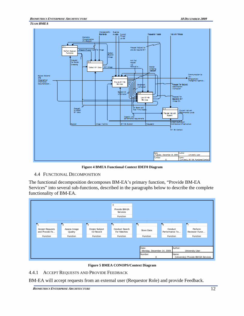
4.3 IDEF0
The IDEF0 diagram below represents the functional context for BM-EA. This diagram shows the inputs, outputs, controls, and mechanisms for BM-EA’s primary function, “Provide BM-EA Services” and how they interact with those systems/entities that are external to BM-EA.
12
BIOMETRICS ENTERPRISE ARCHITECTURE TEAM BMEA
18 DECEMBER 2009
BIOMETRICS ENTERPRISE ARCHITECTURE
Figure 4 BMEA Functional Context IDEF0 Diagram
4.4 FUNCTIONAL DECOMPOSITION
The functional decomposition decomposes BM-EA’s primary function, “Provide BM-EA Services” into several sub-functions, described in the paragraphs below to describe the complete functionality of BM-EA.
0
Provide BM-EAServices
Function
1
Accept Requestsand Provide Fe...
Function
2
Assess ImageQuality
Function
3
Create SubjectID Record
Function
4
Conduct SearchFor Matches
Function
5
Store Data
Function
6
ConductPerformance Te...
Function
7
PerformReviewer Funct...
Function
Date:Monday, December 14, 2009
Author:University User
Number:0
Name:(University) Provide BM-EA Services
Figure 5 BMEA CONOPS/Context Diagram
4.4.1 ACCEPT REQUESTS AND PROVIDE FEEDBACK
BM-EA will accept requests from an external user (Requestor Role) and provide Feedback.
13
BIOMETRICS ENTERPRISE ARCHITECTURE TEAM BMEA
18 DECEMBER 2009
BIOMETRICS ENTERPRISE ARCHITECTURE
4.4.2 ASSESS IMAGE QUALITY
BM-EA will assess the raw image quality of a particular biometric provided by a human subject.
4.4.3 CREATE SUBJECT ID RECORD
BM-EA will create an identification record (biometric template) for each subject who submits a biometric sample to BM-EA.
4.4.4 CONDUCT SEARCH FOR MATCHES
BM-EA will conduct a search of its database to determine matches for the Subject's biometric template.
4.4.5 STORE DATA
BM-EA will store all biometric data related to the subjects.
4.4.6 CONDUCT PERFORMANCE TESTS
The BM-EA will have performance tests conducted by a tester role.
4.4.7 PERFORM REVIEWER FUNCTIONS
BM-EA will have a human reviewer role to add fidelity to the matches found by the automated pattern matching engine.
5 SYSTEMS ENGINEERING METHODOLOGY
The Systems Engineering Management Plan (SEMP) describes the activities, processes, and tools for use by the Biometric Enterprise Architecture (BMEA) Systems Engineering team to support the analysis and design of BMEA.
The objective of the Systems Engineering effort is to assure successful development of BMEA primarily by ensuring clear and accurate system requirements and verifying compliance of the system to those requirements. The BMEA system consists of the means to connect image requestors, suppliers (subjects), reviewers and adjudicators with the BMEA to introduce, search for, validate, enroll and ratify images and biographical information into BMEA for fusion of various image artifacts into a cohesive collective aggregate identity of an individual. The BMEA is set of image and biographical information storage, search and fusion capabilities for supporting the aggregate identity of individuals supporting identification functions within an enterprise.
This SEMP is applicable to all Systems Engineering tasks to be performed in support of the BMEA project. The SEMP is placed under change control upon its initial release and is included as Appendix G.
5.1 PROJECT DEVELOPMENT PROCESS
Team BMEA employs the “Vee” development method from among the traditional lifecycle methods (such as the waterfall method). Using the Vee method, we were able to focus on customer requirements, aligning our process (tasking, requirements, design, development, etc.) to the tools to support providing our solution to the customer. This process method is controlled by our SEMP as provided in Appendix G allowing us to efficiently manage and balance cost, technical and schedule.

14
BIOMETRICS ENTERPRISE ARCHITECTURE TEAM BMEA
18 DECEMBER 2009
BIOMETRICS ENTERPRISE ARCHITECTURE
Figure 6 Team BMEA Systems Engineering Approach
6 BMEA CONTEXT DIAGRAM
The following diagram represents our As-Is, the current, generalized implementation of typical biometric applications across and enterprise. This is represented by and makes heavy use of use of client server applications.
Figure 7 As-Is Biometric Enterprise Architecture

15
BIOMETRICS ENTERPRISE ARCHITECTURE TEAM BMEA
18 DECEMBER 2009
BIOMETRICS ENTERPRISE ARCHITECTURE
7 ARCHITECTURE EVALUATION
Team BMEA conducted a technical marketplace analysis of alternatives (AOA) with respect to biometric applications supporting infrastructure –the underlying technologies supporting enterprise architecture. The AOA is provided in Appendix E. To adequately consider appropriate architectural choices for enterprise Biometrics architecture, the AOS describes technical marketplace needs so an appropriate, heuristically measured choice about which architectural choice to consider from among alternatives occurs. One supporting implementation of our architecture is the “As-Is” alternative which heavily employs the client-server paradigm and is the predominant implementation used currently in the biometrics industry. It is widely recognized that biometrics must undergo a currency transformation in order to be a viable ubiquitous capability along the lines of the telephone and similar commodity technologies. For this reason we chose implementations of Services Oriented Architecture (SOA) and Agent Based capabilities to consider as alternatives to compare to current client server implementations. After careful consideration as expressed in our AOA we concluded and decided to compare current implementations of biometric systems (i. e. the client server model) to the SOA model. We were able to conclude this as a result of our analysis allowed us to construct the set of technology curves depicted in.
Client Server
Service Oriented Archtecture
Agent BasedArchitecture
1985
1990
2010Time
Tech
nolo
g y M
atur
it y
Figure 8 AOA Technology Curves
16
BIOMETRICS ENTERPRISE ARCHITECTURE TEAM BMEA
18 DECEMBER 2009
BIOMETRICS ENTERPRISE ARCHITECTURE
8 TECHNICAL CASE
8.1 BM-EA OPERATIONAL CONCEPT
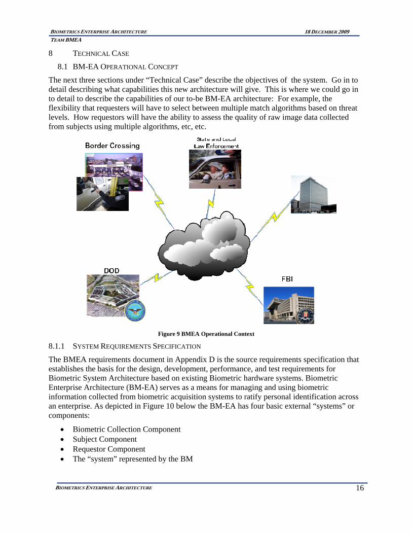
The next three sections under “Technical Case” describe the objectives of the system. Go in to detail describing what capabilities this new architecture will give. This is where we could go in to detail to describe the capabilities of our to-be BM-EA architecture: For example, the flexibility that requesters will have to select between multiple match algorithms based on threat levels. How requestors will have the ability to assess the quality of raw image data collected from subjects using multiple algorithms, etc, etc.
Figure 9 BMEA Operational Context
8.1.1 SYSTEM REQUIREMENTS SPECIFICATION
The BMEA requirements document in Appendix D is the source requirements specification that establishes the basis for the design, development, performance, and test requirements for Biometric System Architecture based on existing Biometric hardware systems. Biometric Enterprise Architecture (BM-EA) serves as a means for managing and using biometric information collected from biometric acquisition systems to ratify personal identification across an enterprise. As depicted in Figure 10 below the BM-EA has four basic external “systems” or components:
• Biometric Collection Component • Subject Component • Requestor Component • The “system” represented by the BM

17
BIOMETRICS ENTERPRISE ARCHITECTURE TEAM BMEA
18 DECEMBER 2009
BIOMETRICS ENTERPRISE ARCHITECTURE
8.1.1.1 The Biometric Collection Component
The Biometric Collection Component is represented by hardware comprised of five different biometric collection systems:
• Fingerprint Collection Machine • Iris Image Collection Machine • Facial Pattern Collection Machine • Voice Pattern Collection Machine • DNA collection capability
These hardware systems all provide an image collection capability used to supply images to the BM-EA.
8.1.1.2 The Requestor Component
The Requestor Component is an external actor/role that initiates biometric collection and (or) biometric verification requirements of a Subject Component. The BM-EA supports registering personal identities of individuals as well as ratifying personal identities from existing, registered identities.
8.1.1.3 The Subject Component
The Subject Component is an identifiable person who is the subject of a biometric collection or verification effort conducted by a “Requestor” Component.
Image ID Request
Results
Image ID Requestor
BM-EA
Image Subject Image
Registry Feedback
Alogrithm Developers
Algorithm Types
Algorithms
System/Quality Manager
Reports
Policies, Controls,Standards
Figure 10 BM-EA External Systems Diagram
8.1.2 SYSTEM DEVELOPMENT DIAGRAMS
• System Description Document: This document lists all operational nodes/stakeholders of the system, and also the information needed to be exchanged among these nodes. In this architecture, for example, image acquisition nodes, image management nodes and image exchange nodes are captured along with all information exchanged among them. This view also captures the internal and external interfaces of this system. It will capture system interfaces and boundaries. It describes the system’s primary engineering elements

18
BIOMETRICS ENTERPRISE ARCHITECTURE TEAM BMEA
18 DECEMBER 2009
BIOMETRICS ENTERPRISE ARCHITECTURE
in a structured manner for review of the physical and behavior of the resulting architecture. Key attributes and relationships are listed.4
8.2 TECHNICAL CASE
8.2.1 BIOMETRIC ARCHITECTURE PERFORMANCE SIMULATION
Please see the Biometric Architecture Performance Simulation Appendix for further details.
8.2.1.1 Hypothetical Application
The team found that modeling and simulation were required to understand the performance characteristics of such a complex system and to demonstrate how a designer would design and tune for a particular application’s unique biometric inputs and stakeholder goals. A hypothetical application was developed based on open-source literature searches of yearly immigrant travelers arriving and exiting the US and DHS current and planned use of biometric systems in US international airports and along the US borders. It was found that face images, Fingerprints, and Iris images are currently being collected either as part of the DHS US-VISIT full-scale operational program or as pilot studies. It was further found that the biometric process begins during the visa application process. A hearing before the Senate Committee on Homeland Security and Governmental Affairs on 9 December 2009 confirmed our application process5:
“Five Years After the Intelligence Reform and Terrorism Prevention Act (IRTPA): Stopping Terrorist Travel”
35M foreigners visit the US yearly and 7.1M apply for a visa in non-visa waiver countries. Biometric vendor literature and independent test results were reviewed to estimate typical biometric system performance parameters. It was found that image quality greatly influences the performance of large-scale systems so precise performance modeling would typically require extensive performance testing with representative data. Since our objective was to determine how major architectural improvements that enable flexible systems can improve performance, we simply set down very reasonable values for our hypothetical application and designed and tuned our system under current as is architectures and our proposed flexible architecture. This provided us feedback to improve our architecture and the designer can use our model to tune designs derived from our architecture given application specifics and testing results from representative image samples and biometric algorithms.
8.2.1.2 Model Components and Findings
Arena was used to model the flow of transactions through our system. See Error! Reference source not found. for the high-level flow.
To tune our system and determine proper computing and human staffing resources, we tracked performance metrics of interest to our stakeholders:
1. Match Accuracy a. Percentage of Unusable Images
4 Systems Engineering Guided Tour, Vitech Corporation 2007. 5 http://hsgac.senate.gov/public/index.cfm?FuseAction=Hearings.Hearing&Hearing_ID=a8365202‐6007‐444a‐8043‐820344cf8be0

19
BIOMETRICS ENTERPRISE ARCHITECTURE TEAM BMEA
18 DECEMBER 2009
BIOMETRICS ENTERPRISE ARCHITECTURE
b. Percentage of Matches Found c. Percentage with False Matches
2. Match Transaction Throughput a. Hourly Transactions
3. Match Result Response Time a. Average Response Time (in Minutes) b. Maximum Response Time (in Minutes)
Visa Photo
Visa Fingerprint
Entry Photo
Foreign Post
Border Crossing
Image Acquisition
Exit Photo
Entry Fingerprint
Exit Fingerprint
Exit Iris Print
Quality Validation
Biometric Matching
Human Review
Final Disposition
Biometric Transaction Flow Through Performance Model
Auto Quality Evaluation
Image Quality Enhancement
(Human)
Unusable Images
Fail
Reject
Stage 1 Match Engine
Image Enrollment
Stage 2 Match Engine
Image Templates
Top Matches
Top Candidate Matches (Human)
Match Determination
No Match Determination
Investigation (Human)
Figure 11 Biometric Transaction Flow through our performance model
In comparing simulation runs under varying stress conditions, we provide the findings in Table 1.
Stress Test # Change Significant Results
1 Increased Transaction Volume: 10%
Under transaction volume stress, our system’s response time averaged 26% lower than for the traditional system.

20
BIOMETRICS ENTERPRISE ARCHITECTURE TEAM BMEA
18 DECEMBER 2009
BIOMETRICS ENTERPRISE ARCHITECTURE
2 Decreased Image Quality Similarly poor results from both systems
3 Increased Threat-level for Five Days
Under the traditional system, hardware could not be increased in such short notice. In our system, the increased hardware sent the system out of balance but with increased human reviewers, overall match performance was increased slightly.
4 Increase in Transaction Volume: 50% Priority
Transactions: 15%
Under the traditional architecture, transaction prioritization cannot be implemented and average response time was 7.2 minutes. Under our architecture, priority placement in queues allowed priority transactions to have an average response time of 1.9 minutes although non-priority transaction response time increased to 10.1 minutes.
Table 1 Architecture Performance Summary Differences
In final conclusion, we believe that our flexible architecture will always provide performance on-par or better than the traditional architecture. Shifting application goals can be better achieved with our flexible architecture.
8.3 BUSINESS CASE
In order to determine the value of an alternative implementation for biometric enterprise architecture, Team Biometrics resolved to assess the relative cost of implementing and maintaining the software that comprises each implementation of biometrics enterprise architecture; the “As-Is” (or current implementation) and the “To-Be” (prospective implementation). The Team has created and Biometrics enterprise architecture using the CORE modeling tool, incorporating the requirements from our requirements document in Appendix D. Using that architecture an assessment of the function points was conducted and recorded as depicted in the Function Point Basis Tables below. These function points were fed along with other factors as specified in Appendix C into a cost modeling tool called the Constructive Cost Model II (COCOMO II) to arrive at a cost level of effort to produce and maintain both the As-Is and To-Be implementations of the biometrics enterprise architecture.

21
BIOMETRICS ENTERPRISE ARCHITECTURE TEAM BMEA
18 DECEMBER 2009
BIOMETRICS ENTERPRISE ARCHITECTURE
Nominal ILF/EIF EO/EI EIPData Elements 20‐50 6‐19 5‐15RecordElements/File Types 6+ 4+ 3+
As‐Is To‐Be As‐Is To‐BeInternal Logic File ILF Nominal Higher High HighExternal Interface File ELF Nominal Lower High AverageExternal Input EIP Nominal Higher High HighExternal Output EO Nominal Higher High HighExternal Inquiry EI Nominal Higher High High
Value
Figure 12 Function Point Table Basis I
As‐Is To‐Be As Is To Be L A H L A HNominal Higher 10 15 2 4 6 4 8 12Nominal Lower 7 5 2 4 6 1 2 3Nominal Lower 4 3 2 4 6 4 8 12Nominal Higher 5 7 2 4 6 4 8 12Nominal Higher 4 6 2 4 6 4 8 12
Complexity WtNumber of Function Points (As‐Is Nominal)
As Is To Be
Figure 13 Function Point Table Basis II
The Function Point Table Bases (Basis I and Basis II) were used to produce COCOMO II generated cost figures as described in the “Sales and Pricing Table” and a “Cash Flow Table” for both the As-Is model and the “To-Be” model as shown below.
The Sales and Pricing Table for both As-Is and To-Be depict the quantity sales over the study timeframe of 5 years. In the As-Is case, since there are existing implementations the assumption is made that there is a steady revenue generation occurring based on adding 5 new installations of As-Is capabilities per year. IN the To-Be case, there are similar sales, but the To-Be sales are offset, in the first two years, by sales of the existing To-Be products.
The Cash Flow tables for the To-Be case only depicts cash flows for the As-Is infrastructure, where the To-Be Cash Flow Table shows cash flows occurring for both systems sales. While the To-Be does start out with selling both As-Is and To-Be capabilities, the To-Be case, ends up just accounting for only To-Be sales, as sales for the As-Is product ceases after the second year.

22
BIOMETRICS ENTERPRISE ARCHITECTURE TEAM BMEA
18 DECEMBER 2009
BIOMETRICS ENTERPRISE ARCHITECTURE
Figure 14 As-Is Sales and Pricing Table
Figure 15 As-Is Cash Flow Table

23
BIOMETRICS ENTERPRISE ARCHITECTURE TEAM BMEA
18 DECEMBER 2009
BIOMETRICS ENTERPRISE ARCHITECTURE
Inputs Yr0 Yr1 Yr2 Yr3 Yr4Sales Current TotalAs Is 5 3 0 0 0 8To Be 0 2 5 5 5 17Total 5 5 5 5 5 25
Pricing Current Price ChangeAs Is 106072 1.1To Be 106072 1.1
Yr1 Yr2 Yr3 Yr4Costs Dev MaintAs Is Expected 324846 282929 443051 693792 1086436To Be Expected 252302 100540 122075 148220 179973As‐Is Low (Opt) 201841 175796 275287 431083 675050To Be Low (Opt) 201841 80432 97660 118576 143978As‐Is High (Pess) 315377 274682 430136 673569 1054767To Be High (Pess) 315377 125675 152594 185275 224966
Discount RateExpected 10.00%
OutputNPV $1,093,548.51
To‐BeSales and Pricing Table
Figure 16 To-Be Sales and Pricing Table
Figure 17 To-Be Cash Flow Table

24
BIOMETRICS ENTERPRISE ARCHITECTURE TEAM BMEA
18 DECEMBER 2009
BIOMETRICS ENTERPRISE ARCHITECTURE
These cash flow values were obtained from using COCOMO to derive the values that are contained in the Sales and Pricing Tables for both the As-Is and the To-Be case.
Using a hourly labor rate of $200 per person (a $115,000 yearly salary) and a nominal schedule, COCOMO II calculated that the expected cost of software development and maintenance for the As-Is case to be $324,846 to develop and maintain existing Biometric software. Corresponding pessimistic and optimistic values were recorded as well and are found in Appendix C.
Likewise for the To-Be situation, COCOMO II calculated the expected cost of software development and maintenance to be $252,302. Corresponding pessimistic and optimistic values were recorded as well and are found in Appendix C.
8.3.1 ASSUMPTIONS AND NPV COMPARISON OF BASE CASE (AS-IS) TO ALTERNATIVE (TO-BE)
In developing a Cost Analysis for the Biometric Enterprise architecture, we made several assumptions to determine our estimations. We assumed that Biometric Enterprise capabilities would sell, in the base case (As-Is) at a flat rate for “As-Is only” sales that As-Is sales would fall while introducing To-Be capabilities as shown in the tables. For value over time, to compare As-Is to To-Be we assume a nominal discount rate of 10% for the five year period. Using these as a basis we set the price for the As-Is situation so that Net Present Value (NPV) without considering other expectations, using the As-Is expected values, is nearly equal to zero.
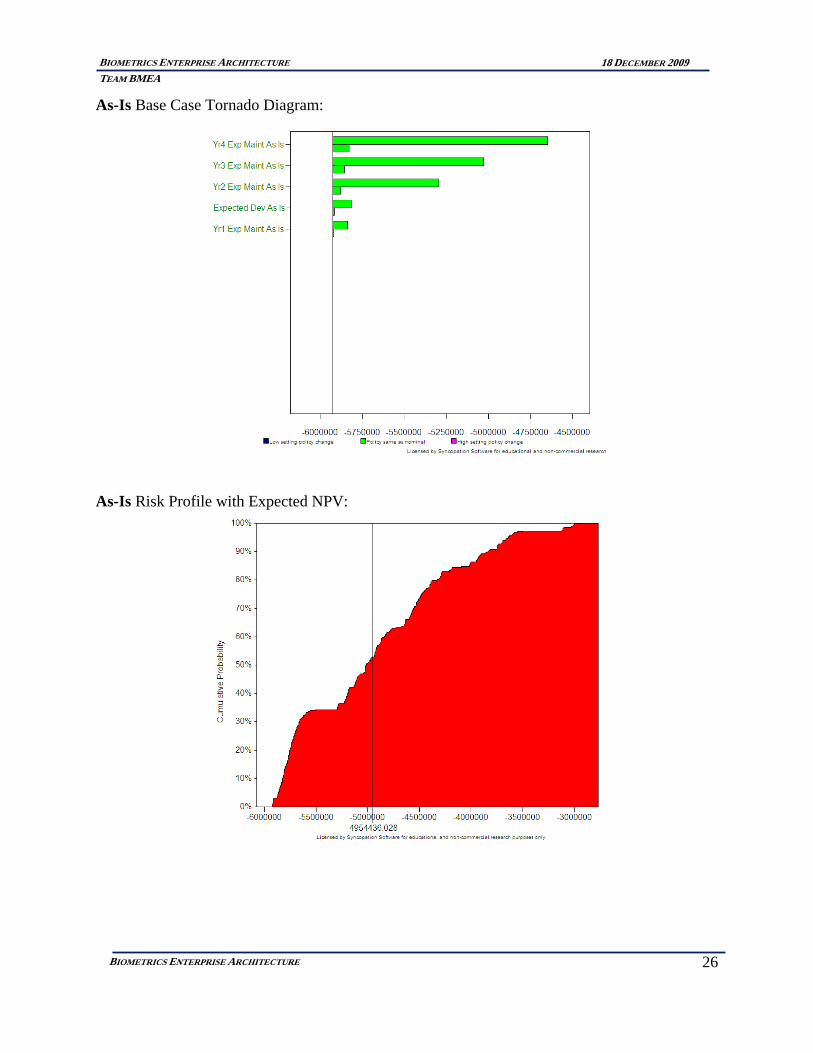
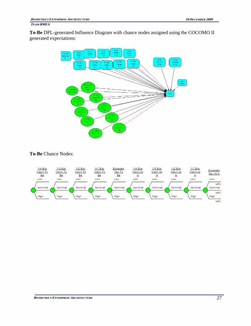
We then used that price to model the NPV of the To-Be case to ascertain the value of implementing the To-Be capabilities. We expect the NPV of the To-Be case to be higher than the NPV of the As-Is case and in fact, when the price is set at $106,072, in the As-Is case, NPV is $10.00 (nearly zero). Using this same price ($106,072) in the To-Be case, the NPV is $1,093,548. This is a significant difference. These figures, from the COCOMO II model, along with the expected, pessimistic and optimistic values for the As-Is and To-Be cases were introduced into Syncopation’s DPL7® decision and risk analysis tool to assess the true nature of the NPV and its relationship to the expected outcomes for both cases. The expectation is the same, that the NPV of the TO-Be case will be grater, by some measure as compared to the As-Is case and the resulting risk profile for the To-Be case will be less than that of the As-Is case. The results are shown below in the form of a DPL7 generated Tornado Diagram and a NPV Risk Profile both for each of the As-Is and the To-Be models:

25
BIOMETRICS ENTERPRISE ARCHITECTURE TEAM BMEA
18 DECEMBER 2009
BIOMETRICS ENTERPRISE ARCHITECTURE
As-Is DPL-generated Influence Diagram with chance nodes assigned using the COCOMO II generated expectations:
As-Is Chance Nodes:
26
BIOMETRICS ENTERPRISE ARCHITECTURE TEAM BMEA
18 DECEMBER 2009
BIOMETRICS ENTERPRISE ARCHITECTURE
As-Is Base Case Tornado Diagram:
As-Is Risk Profile with Expected NPV:
27
BIOMETRICS ENTERPRISE ARCHITECTURE TEAM BMEA
18 DECEMBER 2009
BIOMETRICS ENTERPRISE ARCHITECTURE
To-Be DPL-generated Influence Diagram with chance nodes assigned using the COCOMO II generated expectations:
To-Be Chance Nodes:

28
BIOMETRICS ENTERPRISE ARCHITECTURE TEAM BMEA
18 DECEMBER 2009
BIOMETRICS ENTERPRISE ARCHITECTURE
To-Be Tornado Diagram:
To-Be NPV Risk Profile:
With these results it is very easy to see that the To-Be implementation has a positive NPV while the As-Is implementation is a negative overall expected NPV. There is risk to the To-Be implementation as there is some level of risk in not realizing the expected NPV.

29
BIOMETRICS ENTERPRISE ARCHITECTURE TEAM BMEA
18 DECEMBER 2009
BIOMETRICS ENTERPRISE ARCHITECTURE
8.4 CONCLUSION
In conclusion, we have demonstrated a flexible large-scale biometric architecture that enables the promises of recent cutting-edge software and hardware architectures to reduce costs and provide a flexible weighting among the many stakeholder performance tradeoffs common to large-scale biometric systems. We have shown through price modeling the improved NPV risk profile and through performance modeling we showed the implementation of our architecture.
We recommend that an engineer considering a new large-scale implementation take our performance modeling components re-arranged them specific to their needs, and plug in results from their biometric component testing. Next tune your design with human and processing resources to best achieve your stakeholders’ weighted goals under available budget.

1
BIOMETRICS ENTERPRISE ARCHITECTURE
BIOMETRICS ENTERPRISE ARCHITECTURE TEAM BMEA
18 DECEMBER 2009
APPENDIX A
Appendix A. REFERENCES
REFERENCES
[1] Beizer, Doug. "Kundra's great experiment: Government apps 'store front' opens for business." Federal Computer Week. N.p., n.d. Web. 16 Sept. 2009. <fcw.com/articles/2009/09/15/gov-apps-store.aspx>.
[2] "Biometric Security, Biometric Technology and Biometric Security Systems from Daon.." Biometric Security, Biometric Technology and Biometric Security Systems from Daon.. N.p., n.d. Web. 10 Nov. 2009.
<http://www.daon.com/>.
[3] "Biometrics in Government Post-9/11, Advancing Science, Enhancing Operations." Downloadable PDF Article. N.p., 1 Aug. 2008. Web. 30 Oct. 2009. <www.ostp.gov/galleries/NSTC%20Reports/Biometrics%20in%20Government%20Post%209-11.pdf>.
[4] "Biometrics: Identifying Friend or Foe (+$2 million)." National Institute of Standards and Technology. N.p., n.d. Web. 7 Oct. 2009. <http://www.nist.gov/public_affairs/factsheet/biometrics_budget.htm>.
[5] "DHS | Visa Waiver Program: Passport Requirements Timeline." Department of Homeland Security | Preserving our Freedoms, Protecting America. N.p., n.d. Web. 20 Sept. 2009. <http://www.dhs.gov/files/programs/content_multi_image_0021.shtm>.
[6] "DHS: DHS Begins Test of Biometric Exit Procedures at Two U.S. Airports ." Department of Homeland Security | Preserving our Freedoms, Protecting America. N.p., n.d. Web. 28 Nov. 2009. <http://www.dhs.gov/ynews/releases/pr_1243605893203.shtm>.
[7] "GAO-09-49 Defense Management: DOD Can Establish More Guidance for Biometrics Collection and Explore Broader Data Sharing." Google Docs. N.p., 1 Oct. 2008. Web. 15 Oct. 2009. <docs.google.com/viewer?a=v&q=cache:WDlFNT3Po0EJ:www.gao.gov/new.items/d0949.pdf+www.dos.gov+biometrics&hl=en&gl=us&pid=bl&srcid=ADGEEShmhVyh5l6XkI7yEzoYDCyUTu7P6eleA5hzMBsk1KQOZxZH4ATDI3wn37EBuZI5Z3XyEmJAf7ZTpyiNs0XDY0k6odkCN9U_WOao-RXqJ2UQ8JMh72XgdhSg0xM>.
[8] Hsu, Spencer S.. "DHS readies plan to track foreigners flying from U.S. - washingtonpost.com." washingtonpost.com - nation, world, technology and Washington

2
BIOMETRICS ENTERPRISE ARCHITECTURE
BIOMETRICS ENTERPRISE ARCHITECTURE TEAM BMEA
18 DECEMBER 2009
APPENDIX A
area news and headlines. N.p., n.d. Web. 28 Nov. 2009. <http://www.washingtonpost.com/wp-dyn/content/article/2009/11/07/AR2009110703115.html>.
[9] Jain, Anil, Patrick Flynn, and Arun Ross. Handbook of Biometrics. 1 ed. New York: Springer, 2007. Print.
[10] Klein, Allison. "Mobile print reader makes D.C. area crime-solving a snap - washingtonpost.com." washingtonpost.com - nation, world, technology and Washington area news and headlines. N.p., n.d. Web. 25 Oct. 2009. <http://www.washingtonpost.com/wp-dyn/content/article/2009/10/24/AR2009102402259.html>.
[11] "MBARK - Multimodal Biometric Applicaition Resource Kit - Public Release." NIST ITL home page. N.p., n.d. Web. 4 Oct. 2009. <http://www.itl.nist.gov/iad/894.03/nigos/mbark.html>.
[12] Morgan, Daniel, and William Krouse. "Biometric Identifiers and Border Security: 9/11 Commission Recommendations and Related Issues." Google Docs. N.p., n.d. Web. 11 Oct. 2009. <docs.google.com/viewer?a=v&q=cache:l8RHuJ9pP2oJ:www.au.af.mil/au/awc/awcgate/crs/rs21916.pdf+www.dos.gov+biometrics&hl=en&gl=us&sig=AHIEtbSro3db4-34hUiJm6l3UBVuAelRGw>.
[13] Naone, Erica. "Technology Review: A Silver Lining for the Government's Cloud." Technology Review: The Authority on the Future of Technology. N.p., n.d. Web. 21 Sept. 2009. <http://www.technologyreview.com/computing/23501/?a=f>.
[14] Ramesh, Randeep. "1.2bn population of India to be given biometric ID cards | World news | The Guardian." Latest news, comment and reviews from the Guardian | guardian.co.uk. N.p., n.d. Web. 24 Sept. 2009. <http://www.guardian.co.uk/world/2009/sep/16/india-population-biometric-id-cards>.
[15] "Receiver operating characteristic - Wikipedia, the free encyclopedia." Wikipedia, the free encyclopedia. N.p., n.d. Web. 4 Sept. 2009. <http://en.wikipedia.org/wiki/Receiver_operating_characteristic>.
[16] "Registry of USG Recommended Biometric Standards." Downloadable PDF Article. N.p., n.d. Web. 24 Oct. 2009. <www.biometrics.gov/Standards/StandardsRegistry.pdf>.

3
BIOMETRICS ENTERPRISE ARCHITECTURE
BIOMETRICS ENTERPRISE ARCHITECTURE TEAM BMEA
18 DECEMBER 2009
APPENDIX A
[17] "ScienceDirect - Biometric Technology Today : DoS awards record breaking biometric deal ." ScienceDirect - Home. N.p., n.d. Web. 23 Oct. 2009. <http://www.sciencedirect.com/science?_ob=ArticleURL&_udi=B6W70-4DS8BCX-1&_user=650615&_rdoc=1&_fmt=&_orig=search&_sort=d&_docanchor=&view=c&_searchStrId=1141072646&_rerunOrigin=google&_acct=C000035118&_version=1&_urlVersion=0&_userid=650615&md5=bf0491ca67>.
[18] "Standards." Biometrics.gov. N.p., n.d. Web. 24 Oct. 2009. <www.biometrics.gov/Standards >.
[19] "Statement for the Record, Rand Beers, Under Secretary, National Protection and Programs Directorate, Department of Homeland Security, Before the United States Senate Committee on Homeland Security and Governmental Affairs, Terrorist Travel ." Downloadable PDF File. N.p., n.d. Web. 9 Dec. 2009. <hsgac.senate.gov/public/index.cfm?FuseAction=Files.View&FileStore_id=16e8ac24-2fb2-4672-bf28-4c1e6f72113b>.
[20] "Systems Biophysics - Research - Face Recognition by EGM." Institut für Neuroinformatik. N.p., n.d. Web. 27 Sept. 2009. <http://www.neuroinformatik.ruhr-uni-bochum.de/ini/VDM/research/computerVision/graphMatching/identification/faceRecognition/contents.html>.
[21] Wayman, James, Anil Jain, Davide Maltoni, and Dario Maio. Biometric Systems: Technology, Design and Performance Evaluation. 1 ed. New York: Springer, 2004. Print.
[22] "YouTube- From Fingerprints to a New Era of Biometrics." YouTube - Broadcast Yourself. N.p., n.d. Web. 26 Oct. 2009. <http://www.youtube.com/watch?v=ASjsyONRkEc&feature=related>.
[23] Cloud Computing-“What is its Potential Value for Your Company.” San Francisco, CA: CBS Interactive Inc., 2009. Print.

1
BIOMETRICS ENTERPRISE ARCHITECTURE
BIOMETRICS ENTERPRISE ARCHITECTURE TEAM BMEA
18 DECEMBER 2009
APPENDIX B
Appendix B. BIOMETRIC ARCHITECTURE PERFORMANCE SIMULATION
1. Hypothetical Application
The team found that modeling and simulation were required to understand the performance of such a complex system. A hypothetical application was developed based on open-source literature searches of yearly immigrant travelers arriving and exiting the US and also DHS’s current and planned use of biometric systems in US international airports and along the US borders. It was found that face images, Fingerprints, and Iris images are currently being collected either as part of the DHS US-VISIT full-scale operational program or as pilot studies. It was further found that the biometric process begins during the visa application process.
35M foreigners visit the US yearly and in non-visa waiver countries, 7.1M apply for a visa overseas. Biometric vendor literature and independent test results were reviewed to estimate typical biometric system performance parameters and characteristics. It was found that image quality greatly influences the performance of large-scale systems so precise performance modeling requires extensive performance testing with representative data. Since our objective was to determine how major architectural improvements that enable flexible systems can improve performance, we simply set down very reasonable values for our hypothetical application and designed and tuned our system under current “as is” architectures and our proposed flexible architecture. This provided us feedback to improve our architecture and the designer can use our model to tune designs derived from our architecture given their particular application specifics and testing results from representative image samples and biometric algorithms.
2. Major Biometric Transaction Model Components
The flowchart of the major components of our model is provided in Figure 18. Components in orange are transaction queues within processes that include humans-in-the-loop. Grey boxes are transaction origination or termination processes. We did not include the adjudicator within our model since much of his work is to review cases overall. We also did not include the acquisition process except to characterize the transactions that come out of that process (poisson transaction creation distributions with given quality and biometric modalities). From research studies, we found that human experts and machine performance are quite comparable. However, humans are much slower and obviously don’t have time to match an image against millions of images. Humans can however, review the very top automated matches. Since the images that they correctly identify do not precisely correlate with the images that the automated system identifies, human resources can be quite effective in-the-loop when match performance outweighs costs. We identified and tracked the key external measures of performance of interest to our stakeholders:
4. Match Accuracy a. Percentage of Unusable Images b. Percentage of Matches Found c. Percentage with False Matches
5. Match Transaction Throughput a. Hourly Transactions

2
BIOMETRICS ENTERPRISE ARCHITECTURE
BIOMETRICS ENTERPRISE ARCHITECTURE TEAM BMEA
18 DECEMBER 2009
APPENDIX B
6. Match Result Response Time a. Average Response Time (in Minutes) b. Maximum Response Time (in Minutes) c. Priority Transaction6 Average Response Time (in Minutes) d. Priority Transaction6 Maximum Response Time (in Minutes)
Figure 18 - Performance Simulation Process Flowchart - Hypothetical Border Application
Also distinctive to our architecture is the use of virtualized matchers allowing immediate re-allocation of systems between modalities (face, iris, and fingerprint). As presented later in this appendix, we found that when the system is under mild throughput volume stress, this flexibility resulted in 26% lower average response times while providing no significant change to the match performance and using no increased human or machine resources. This was accomplished through the flexible re-allocation of stage 2 match systems only. Unfortunately, we discovered that similar re-allocation of stage 1 match systems was not possible since stage 1 matchers
6 Priority Transactions require real-time match search responses. Typically a human submits and is waiting for the response. When using priority transactions in our modeled example, we assumed that 15% of all transactions from each modality (face, iris, and fingerprint) were considered priority transactions. Our architecture provides for flexible response time prioritization by time due or by static priority depending on the application and implements this prioritization through placement of new transactions within each queue.

3
BIOMETRICS ENTERPRISE ARCHITECTURE
BIOMETRICS ENTERPRISE ARCHITECTURE TEAM BMEA
18 DECEMBER 2009
APPENDIX B
require significant dedicated memory space for each modality and costs for providing sufficient space would be prohibitive compared with simply adding additional servers.
3 Resources and Schedules
In creating our hypothetical example, we made some common-sense assumption about the distributions of transactions through the week and throughout the day and we assigned human reviewers in three shifts during each day with fewer reviewers during the third shift. Since response-time is one of our performance measures, we had to assign reviewers to all shifts rather than let the fewer transactions received overnight to linger all night. Automated systems were considered a constant capacity resource… although our cloud computing based architecture provides for the near real-time reallocation of servers to and from the application, we believe that in most real world datacenters there may not be a significant advantage to finding night work for these systems and therefore possible savings may be low. However, non priority response time transactions could benefit with improved match accuracy by running over night. In our hypothetical application, we emphasized response time over marginally improved match performance and therefore did not explore the possible increase in match accuracy through better allocation of slow processing periods; however, we do believe that our models would demonstrate this advantage of our architecture.
Figure 19 - Hardware, Reviewers, Border crossings and Visa Application Processing
To allow reasonable runtime simulations representing 5-days of border crossings and visa applications, we scaled our application down to 10% of actual transactions. All results are based
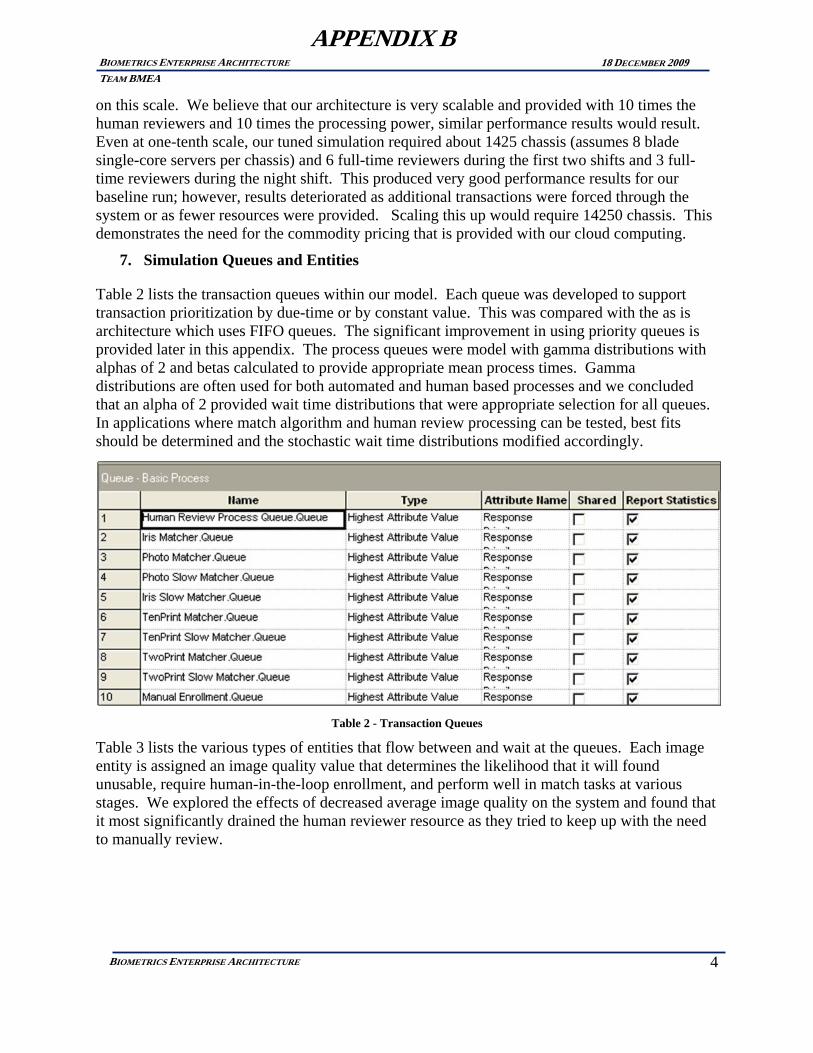
4
BIOMETRICS ENTERPRISE ARCHITECTURE
BIOMETRICS ENTERPRISE ARCHITECTURE TEAM BMEA
18 DECEMBER 2009
APPENDIX B
on this scale. We believe that our architecture is very scalable and provided with 10 times the human reviewers and 10 times the processing power, similar performance results would result. Even at one-tenth scale, our tuned simulation required about 1425 chassis (assumes 8 blade single-core servers per chassis) and 6 full-time reviewers during the first two shifts and 3 full-time reviewers during the night shift. This produced very good performance results for our baseline run; however, results deteriorated as additional transactions were forced through the system or as fewer resources were provided. Scaling this up would require 14250 chassis. This demonstrates the need for the commodity pricing that is provided with our cloud computing.
7. Simulation Queues and Entities
Table 2 lists the transaction queues within our model. Each queue was developed to support transaction prioritization by due-time or by constant value. This was compared with the as is architecture which uses FIFO queues. The significant improvement in using priority queues is provided later in this appendix. The process queues were model with gamma distributions with alphas of 2 and betas calculated to provide appropriate mean process times. Gamma distributions are often used for both automated and human based processes and we concluded that an alpha of 2 provided wait time distributions that were appropriate selection for all queues. In applications where match algorithm and human review processing can be tested, best fits should be determined and the stochastic wait time distributions modified accordingly.
Table 2 - Transaction Queues
Table 3 lists the various types of entities that flow between and wait at the queues. Each image entity is assigned an image quality value that determines the likelihood that it will found unusable, require human-in-the-loop enrollment, and perform well in match tasks at various stages. We explored the effects of decreased average image quality on the system and found that it most significantly drained the human reviewer resource as they tried to keep up with the need to manually review.

5
BIOMETRICS ENTERPRISE ARCHITECTURE
BIOMETRICS ENTERPRISE ARCHITECTURE TEAM BMEA
18 DECEMBER 2009
APPENDIX B
Table 3 - Transaction Queues
8. Animated high-level model user interface
Our models were developed using Arena which provides an animated interface. We found this interface to be very useful when tuning the required resource and in validating our model. Figure 20 is the highest level of our model with queues and the logic hidden in each of the steps. Image transactions flow from left to right through this model and all the performance statistics are collected from each transaction once the transaction finishes. During actual statistical collection runs, animation was turned off to significant increase simulation time. A typical run representing 5-days of transactions (10% scale as discussed earlier in this appendix) required only a few minutes to run. Both entities flowing through the queues and the pictures representing some of the queues were animated to identify their location, modality, and busy state. Calendar and time were also helpful to following the times of day when the queues may fill and additional resources were needed.
The results from customized counts gathered during a “5-day” run are shown in Table 4. The abbreviations included in this table are:
CR – Correct Reject (The image had no matches in the database and none were found)
FR – False Reject (The image had a match in the database but was not found)
CA – Correct Accept (The image had a match in the database and it was correctly identified)
FA – False Accept (The image had no matches in the database but an image was incorrectly identified)

6
BIOMETRICS ENTERPRISE ARCHITECTURE
BIOMETRICS ENTERPRISE ARCHITECTURE TEAM BMEA
18 DECEMBER 2009
APPENDIX B
Figure 20 - Arena Animated Interface
Biometric systems represent the likelihood of match errors through traditional ROC tradeoff curves. The degree of similarity that two images must have to be considered a match is the match threshold. This match threshold can be adjusted to manage the natural tradeoff that always exists between the risks of not identify match and the risks of identify non-matches as matches. In our hypothetical application, we found that the first type of risk represents the possibility of not identifying someone who goes under multiple aliases or may be contained in a most want watch list. While the second type of risk is that the human reviewers are overwhelmed by incorrect matches and workload is significantly increased. Through this ROC curve, one can properly adjust the workload and missed matches. Significant testing must be performed with the actual match algorithms and representative quality of images to determine the threshold that best balances costs and performance.

7
BIOMETRICS ENTERPRISE ARCHITECTURE
BIOMETRICS ENTERPRISE ARCHITECTURE TEAM BMEA
18 DECEMBER 2009
APPENDIX B
Table 4 - Custom Event Counts Accumulated during 5 days (actual 10% scale)
9. Modeling with Arena
Figure 21 is the main interface that we created to monitor runs and collect statistics. During runs that allowed the queues to very often fall to zero at night, each of the five days could be considered separate runs. When multiple replication of the simulation was run, variability between runs was found to be similar to these inter-day results and to be small and insignificant. It was therefore decided that multiple sample statistics for a single configuration were not required since each run was found to produce an insignificant difference in results.
In applications where significant test data is available for more accurate conclusions, these variations may be more significant; however, given the large magnitude of transactions that flow through the system each day, variability between similar days would be insignificant. Obviously, the real world issues of busier and slower days need to be considered in the tuning of real world designs. We simply took the number of transactions per year and divided by either the number of weekdays for the visa applications and by the number of total days for the border crossings… this could be considered best case since any variability could result in performance issues. Varying the rate throughout a given simulation should be included in a real world simulation. We only varied the rate based on the time of day. We did perform tests at various transaction throughput to determine the sensitivity of the system to such variability as described later in this appendix.

8
BIOMETRICS ENTERPRISE ARCHITECTURE
BIOMETRICS ENTERPRISE ARCHITECTURE TEAM BMEA
18 DECEMBER 2009
APPENDIX B
Figure 21 - Arena Provides Major Queue Lengths
The Figure 21 interface monitors the stage-1 match queues (for iris, face, and fingerprint), the stage-2 match queues, and the human review queue (which includes the manual enrollment queue as well as the match review queue since they require the same resource type). Also included on the right of the diagram is a graph of the average and maximum response time for all terminated transactions during the simulations measured in minutes. The metrics that were considered to be most critical to our stakeholders were specifically calculated and their values provided in the interface. Variables in the model are easily altered and the simulation re-run to contrast results. Note that in the displayed simulation run, the Human Review Queue continues to grow significantly during each day resulting in rather large response times even when overall the reviewers are only busy an average of 6.57 out of 7.00 available time units due to slow periods during the night after the work backlog has been worked down.
Figure 22 is the high level simulation module for generating the required distributions of transaction types to feed the rest of the model. All transactions in our model originate from this module and then exit to the right. They exit from the first (higher) line if they did enroll successfully and then move the match engines module. They exit from the second (lower) line if they did not enroll successfully and move to a human in the loop manual attempt to enroll. The human might mark certain landmarks within the biometric image to help the enrollment algorithm process the image.

9
BIOMETRICS ENTERPRISE ARCHITECTURE
BIOMETRICS ENTERPRISE ARCHITECTURE TEAM BMEA
18 DECEMBER 2009
APPENDIX B
Figure 22 - Main Simulation Module that Creates Required Distributions
At the other end of the model flow are a number of modules that trap and record the final disposition of every completed transaction. Figure 23 depicts the module that handles all transactions that were matched in the automated matcher and validated by the human reviewer as a match and are a correct match. These transactions are then split by the various modalities (iris, visa photo, visit photo, and fingerprint) for analysis. Performance statistics for priority transactions are also separated and counted separately.
Figure 23 - An example of one of the modules that traps and bins the transactions for the collection of statistics

10
BIOMETRICS ENTERPRISE ARCHITECTURE
BIOMETRICS ENTERPRISE ARCHITECTURE TEAM BMEA
18 DECEMBER 2009
APPENDIX B
Figure 24 is the high level manual enrollment module which includes a process with an animated queue. At time to this screen capture, six images were awaiting an available human reviewer to re-attempt a failed automated enrollment. With our configuration, the human resources that provide match review also provide the manual enrollment attempts so, although contain within different modules, both of these queues will tend to increase at the same time as the reviews become overloaded.
Figure 24 - Manual Enrollment Module
Figure 25 – High-level Human Review Processing Flow

11
BIOMETRICS ENTERPRISE ARCHITECTURE
BIOMETRICS ENTERPRISE ARCHITECTURE TEAM BMEA
18 DECEMBER 2009
APPENDIX B
Figure 25 depicts the processing flow for the manual match review and lookup of the review’s correctness. Most paths provide a count of entities that have flowed through since the beginning of the simulation run.
The matching engine which, in our architecture, handles the matching of iris images, 10-prints, 2-prints, and face images against the entire enrolled biometric databases is shown in Figure 26. The architecture includes a first stage which holds all templates in memory for speed and a second stage which uses a larger and more accurate template. The second stage only compares the biometric image to images that have been determined by the first stage to be a possible match. The second stage can look-up the templates of the candidate images and therefore does not store these larger templates in memory. We determined that these differences between stage 1 and stage 2 type matchers would allow stage 2 matchers to be virtualized and act on any modality; however, stage 1 matchers are less able to take advantage of our architecture since these must remain specialized to a modality. Stage 1 matchers can perform stage 2 matches as needed for efficient real-time hardware resource allocation.
Images that were not automatically enrolled and were also not enrolled after human attempts to assist in the enrollment, end up in the “Unenrollable” bin at the bottom of this module rather than run through the stage-1 and then stage-2 matching queues and contributes to the “% of Unusable Images” performance metric.
Figure 26 - High-level 2-stage match engine module
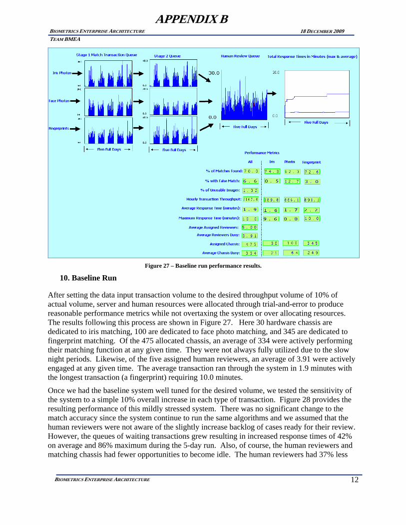
12
BIOMETRICS ENTERPRISE ARCHITECTURE
BIOMETRICS ENTERPRISE ARCHITECTURE TEAM BMEA
18 DECEMBER 2009
APPENDIX B
Figure 27 – Baseline run performance results.
10. Baseline Run
After setting the data input transaction volume to the desired throughput volume of 10% of actual volume, server and human resources were allocated through trial-and-error to produce reasonable performance metrics while not overtaxing the system or over allocating resources. The results following this process are shown in Figure 27. Here 30 hardware chassis are dedicated to iris matching, 100 are dedicated to face photo matching, and 345 are dedicated to fingerprint matching. Of the 475 allocated chassis, an average of 334 were actively performing their matching function at any given time. They were not always fully utilized due to the slow night periods. Likewise, of the five assigned human reviewers, an average of 3.91 were actively engaged at any given time. The average transaction ran through the system in 1.9 minutes with the longest transaction (a fingerprint) requiring 10.0 minutes.
Once we had the baseline system well tuned for the desired volume, we tested the sensitivity of the system to a simple 10% overall increase in each type of transaction. Figure 28 provides the resulting performance of this mildly stressed system. There was no significant change to the match accuracy since the system continue to run the same algorithms and we assumed that the human reviewers were not aware of the slightly increase backlog of cases ready for their review. However, the queues of waiting transactions grew resulting in increased response times of 42% on average and 86% maximum during the 5-day run. Also, of course, the human reviewers and matching chassis had fewer opportunities to become idle. The human reviewers had 37% less

13
BIOMETRICS ENTERPRISE ARCHITECTURE
BIOMETRICS ENTERPRISE ARCHITECTURE TEAM BMEA
18 DECEMBER 2009
APPENDIX B
idle time while the chassis had 23% less time. This might be a desired point if response time was less critical and costs of human reviewers and match chassis were more critical.
Fortunately, our architecture allows for multiple uses of the chassis to enable real-time flexible allocation among iris, face photo, and fingerprint matching duties. We implemented this change in our model without changing any total resources and found that the added flexibility resulted in a lower average response time as we had hoped. The response time was 26% lower with an average of 2 minutes which might be considered acceptable. Our design allowed us to process additional throughput volume without increasing our costs including labor or hardware costs.
Figure 28 – Stress Test 1
Once we had the baseline system well tuned for the desired volume, we tested the sensitivity of the system to a simple 10% overall increase in each type of transaction. Figure 28 provides the resulting performance of this mildly stressed system. There was no significant change to the match accuracy since the system continue to run the same algorithms and we assumed that the human reviewers were not aware of the slightly increase backlog of cases ready for their review. However, the queues of waiting transactions grew resulting in increased response times of 42% on average and 86% maximum during the 5-day run. Also, of course, the human reviewers and matching chassis had fewer opportunities to become idle. The human reviewers had 37% less idle time while the chassis had 23% less time. This might be a desired point if response time was less critical and costs of human reviewers and match chassis were more critical.
Fortunately, our architecture allows for multiple uses of the chassis to enable real-time flexible allocation among iris, face photo, and fingerprint matching duties. We implemented this change

14
BIOMETRICS ENTERPRISE ARCHITECTURE
BIOMETRICS ENTERPRISE ARCHITECTURE TEAM BMEA
18 DECEMBER 2009
APPENDIX B
in our model without changing any total resources and found that the added flexibility resulted in a lower average response time as we had hoped. The response time was 26% lower with an average of 2 minutes which might be considered acceptable. Our design allowed us to process additional throughput volume without increasing our costs including labor or hardware costs.
Figure 29 - In stress test 2
In stress test 2, depicted in Figure 29, the throughput remained elevated 10% while the photo quality was reduced by 20%. The reduced image quality resulted in significant increases in the transaction response times as well as to the number of unusable images (1.3 percent to 2.9%). The increased response times were due to backlogs in image match reviews as reviewers needed to increase the time attempting to process images that would not automatically enroll. In addition the poorer quality images resulted in lower match accuracy performance although not as significantly as we may have predicted. Performance of match algorithms should be tested with various levels of quality images to more precisely model this effect for a specific application. Also shown here is the work schedule for the operators since we will need to increase staff to handle these lower quality images. Since our analysis did not include the image acquisition equipment and process, we did not look at possible tradeoffs of adding reviewers vs. improving the front-end image acquisition process. We assumed that the quality of images received may change but that we do not have control of this change and can only try to adapt the system to these new inputs.

15
BIOMETRICS ENTERPRISE ARCHITECTURE
BIOMETRICS ENTERPRISE ARCHITECTURE TEAM BMEA
18 DECEMBER 2009
APPENDIX B
Figure 30 - Adjusting staff levels higher after lower quality images
We next adjusted our staff levels until we regained our previous performance. As shown in Figure 30, we had to increase the first two shifts up by two staff reviewers. We were able to hold the night shift at a staff of three reviewers.
A significant advantage to our architecture built on a cloud computing model, over previous architectures is the flexibility of quickly allocating and de-allocating hardware. We pay only for the hardware allocated to the task at any given time. To determine the advantage of this, for stress test 3, we elevated the threat level for a five day period while keeping our demand elevated and our image qualities reduced compared with the original baseline. Increases to the threat level will add to the importance of finding matches with less concern for cost. One method for accomplishing this is to add hardware to the slower but more accurate stage 2 matchers so that they can crunch on more of the matches returned from the faster but less accurate stage 1 matchers. This resulted in a slight increase of 69.5% of matches found rather than 67.9% found. This would allow 5% of the matches that would have gone undetected to be found. If every match is important without regard to cost then this increased accuracy might be worthwhile. Unfortunately, the increased stage 2 matchers sent the system out of balance and the human reviewers were unable to maintain a short queue throughout the day. Response times again became unacceptable with an average overall wait of 20 minutes including nearly 32 minutes for fingerprint results. See Figure 14.
We found that the night shift needed to be increased by 2 staff reviewers to bring the system back into balance as shown in Figure 32.

16
BIOMETRICS ENTERPRISE ARCHITECTURE
BIOMETRICS ENTERPRISE ARCHITECTURE TEAM BMEA
18 DECEMBER 2009
APPENDIX B
Figure 31 - Stress test 3 – Surge hardware
Figure 32 - Increase Nightshift Staff allowed

17
BIOMETRICS ENTERPRISE ARCHITECTURE
BIOMETRICS ENTERPRISE ARCHITECTURE TEAM BMEA
18 DECEMBER 2009
APPENDIX B
Response time continued to be slow and a further increase of hardware by 50% was used to restore response times while maintaining the higher match accuracy critical during the weeklong elevated threat condition. This is shown in Figure 33. Thanks to our architecture, we could now flexibly reduce the hardware and staff reviewers as soon as the elevated threat conditions ended and reduce our costs.
Figure 33 - Further increased hardware 50% to bring response time down.
We next demonstrate through simulation one of the advantages of an SOA architecture allowing for the stage 1 and stage 2 matchers to be separate services provided by different vendors. Since the results from algorithms provided by two vendors are likely to be someone less correlated than from algorithms of the same vendor, then assuming that both vendors have similar performance, a system that makes use of both may result in improved performance. One way to fuse their results is to have the top results from the first vendor’s fast algorithm feed the second vendor’s slow algorithm. Since we would need significant test results to determine this improvement, we could only make some assumptions and then run the simulation for performance based on those assumptions. As seen in Figure 34, match performance was improved. Results from various vendor system could be combined in other arrangements and adjusted over time thanks to our architecture, SOA, and cloud computing.

18
BIOMETRICS ENTERPRISE ARCHITECTURE
BIOMETRICS ENTERPRISE ARCHITECTURE TEAM BMEA
18 DECEMBER 2009
APPENDIX B
Figure 34 - SOA Architecture allow Alternative Stage 1 and Stage 2 Matchers
Figure 35 - Sudden increase in transactions by 50%.

19
BIOMETRICS ENTERPRISE ARCHITECTURE
BIOMETRICS ENTERPRISE ARCHITECTURE TEAM BMEA
18 DECEMBER 2009
APPENDIX B
Next we further increase throughput demand to 50% above baseline from the 10% above baseline to simulate a sudden surge in demand. We found that the hardware that had been added during the threat conditions was sufficient to handle this load but the manual reviewers were again overwhelmed. See Figure 35.
This time, we assume that we are out of funding and cannot add staff during this transaction surge period. However, we know that 15% of the transactions require real-time responses (the person who submitted the image may be waiting for the match responses) while the other 85% are of lower priority. The 7 minute average and 104 minute maximum response time is not acceptable. Our design allows for prioritization of the match transactions by either time-due or by constant priority. It does this by sticking each transaction new to a queue ahead of all transactions with lower priority or time-due stamps. The high priority transactions now had an acceptable average response time of 1.9 minutes with a maximum of 8.9 minutes. Of course, the non-priority response times were increased but this might be acceptable for many applications.
Figure 36 - Priority Transactions
11. Summary of Results and Conclusions
For a hypothetical border crossing application, we developed a detailed simulation of a design instantiation based on our proposed architecture. We demonstrated that the flexibility that our architecture enables can provide real performance benefits under some conditions and never performed worse than the traditional system. Our system was sized based on requirements obtained from open-source literature. Particularly when the environment changes, such as changes in threat levels, throughput levels, image quality, or multiple prioritizations of transactions, current systems cannot be easily or quickly modified in response. Thanks to the use of SOA architecture, cloud computing, and transaction prioritization techniques significant value

20
BIOMETRICS ENTERPRISE ARCHITECTURE
BIOMETRICS ENTERPRISE ARCHITECTURE TEAM BMEA
18 DECEMBER 2009
APPENDIX B
is offered. Our model was built to allow the results from biometric algorithm and human review testing to be used to generate a simulation estimating real-world performance. Our model also allows us to conduct what-if analysis for best designs for a given application. Tools provided by Arena allow various methods for optimizing design parameters through multiple simulations within the parameter space.
Count Application Parameters
7,100,000 US Visas Issued (2008)
130,000,000 US Border Enrolled Travelers (2008)
35,000,000 Foreign Visitors Entering U.S./Year
35,000,000 Foreign Visitors Exiting U.S./Year
50 Resource: Human Reviewers per shift
4750 Resource: Total Hardware Chassis
Table 5 – Full Scale Transactions
The metrics of interest to our stakeholders include:
Match Accuracy • Percentage of Unusable Images • Percentage of Matches Found • Percentage of False Matches
Match Transaction Throughput Match Result Response Time
• Average Response Time • Maximum Response Time • Priority Transaction Response
We showed that our architecture performs better than the traditional architecture under shifting environments to maintain these performance requirements.

21
BIOMETRICS ENTERPRISE ARCHITECTURE
BIOMETRICS ENTERPRISE ARCHITECTURE TEAM BMEA
18 DECEMBER 2009
APPENDIX B
Under Stress Test #1, we subjected our baseline system a 10% additional throughput volume beyond its intend volume. This resulted in a 42% increase in overall system’s average response time and an 86% increase in the maximum response time. Our architecture allows virtualized services to service any of the stage 2 processes for any of the biometric modalities. When we switched on this capability, our architecture allowed us to lower our average response time by 26% compared with the traditional architecture which does not allow for virtualized servers for multiple modality roles. We had no loss in other performance metrics.
Under Stress Test #2, we also decreased the quality of images and found that this caused a significant increase in the backlog for reviewers and significantly lowered our match accuracies. By adding two additional staff to the night shift and adding 50% more hardware, we brought our response time back down. However, the match accuracy remained stubbornly high. The results under this test were similar between our architecture and the traditional architecture.
Under Stress Test #3, we increased the Threat Level for a five day period. This has the effect of increasing the critical need to locate matches without regard to additional costs needed to locate these matches. Since the traditional model was not a cloud-based system, we were unable to respond in this limited period with increased hardware. Also, our SOA internal architecture allowed us to swap to more accurate vendor’s stage 2 algorithms while maintaining our original vendor for the stage 1 matchers. The overall result was a 1-2% increase in matches found and a very significant improvement in response time.
Under Stress Test #4, we significantly increased volume by 50% but designated 15% of transactions to be priority transactions. Under the traditional system, all transactions averaged 7.2 minutes. Under our architecture, priority placement in queues allowed priority transactions to have an average response time of 1.9 minutes although non-priority transaction response time increased to 10.1 minutes.
1 Increased Transaction Volume: 10%
Under transaction volume stress, our system’s response time averaged 26% lower than for the traditional system.
2 Decreased Image Quality Similarly poor results from both systems
3 Increased Threat-level for Five Days
Under the traditional system, hardware could not be increased in such short notice. In our system, the increased hardware sent the system out of balance but with increased human reviewers, overall match performance was increased slightly.

22
BIOMETRICS ENTERPRISE ARCHITECTURE
BIOMETRICS ENTERPRISE ARCHITECTURE TEAM BMEA
18 DECEMBER 2009
APPENDIX B
4 Increase in Transaction Volume: 50% Priority Transactions: 15%
Under the traditional architecture, transaction prioritization cannot be implemented and average response time was 7.2 minutes. Under our architecture, priority placement in queues allowed priority transactions to have an average response time of 1.9 minutes although non-priority transaction response time increased to 10.1 minutes.
Table 6 - Performance Summary Differences
In final conclusion for our performance simulation testing, we believe that our flexible architecture will always provides performance on-par or better than the traditional architecture. Shifting application goals can be better achieved with our flexible architecture. Our model can be used with real world biometric applications once the biometric algorithms and human reviewers are tested for their performance characteristics.

Friday, November 13, 2009
Appendix C
23
BIOMETRICS ENTERPRISE ARCHITECTURE
Appendix C. FUNCTION POINT ANALYSIS VALUES The following settings were used to establish the Net Present Value (NPV) in both the As-Is and the To-Be models. The values for the To- be are considered “nominal” for establishing the client server applications development and maintenance estimates. These resulting estimates were put into a DPL 7 model to assess the cumulative risk based on NPV. These two NPV values were compared directly. The As-Is model’s NPV was set to near zero (as close to zero as possible) by manipulating the price of As-Is revenue and cost data. That price was transferred to the To-Be revenue and cost data and the NPV was calculated. These values were used in the DPL 7 model to arrive at the cumulative NPV and the associated risk. As-Is Revenue Cost and Cash Flow worksheets:
As-Is Sales and Pricing Table

Friday, November 13, 2009
Appendix C
24
BIOMETRICS ENTERPRISE ARCHITECTURE
As-Is Cash Flow Table
Inputs Yr0 Yr1 Yr2 Yr3 Yr4Sales Current TotalAs Is 5 3 0 0 0 8To Be 0 2 5 5 5 17Total 5 5 5 5 5 25
Pricing Current Price ChangeAs Is 106072 1.1To Be 106072 1.1
Yr1 Yr2 Yr3 Yr4Costs Dev MaintAs Is Expected 324846 282929 443051 693792 1086436To Be Expected 252302 100540 122075 148220 179973As‐Is Low (Opt) 201841 175796 275287 431083 675050To Be Low (Opt) 201841 80432 97660 118576 143978As‐Is High (Pess) 315377 274682 430136 673569 1054767To Be High (Pess) 315377 125675 152594 185275 224966
Discount RateExpected 10.00%
OutputNPV $1,093,548.51
To‐BeSales and Pricing Table
To-Be Sales and Pricing Table

Friday, November 13, 2009
Appendix C
25
BIOMETRICS ENTERPRISE ARCHITECTURE
To-Be Cash Flow Table
Project To‐Be As‐Is
Scale Factor
Precedentedness NOM EH Development Flexibility NOM VL Architecture/Risk Resolution LOW NOM Team Cohesion HI LOW Process Maturity NOM LOW
Schedule NOM NOM
Sizing Method Function
PointsBreakage % 0 10% Model Size in Function Points
Language Java C++ Function Type
ILF L 4 2

Friday, November 13, 2009
Appendix C
26
BIOMETRICS ENTERPRISE ARCHITECTURE
A 8 4 H 12 6
EIF L 1 2 A 2 4 H 3 6
EI L 4 2 A 8 4 H 12 6
EO L 4 2 A 8 4 H 12 6
ExtInq L 4 2 A 8 4 H 12 6
Collect BMEA Data EAF Product RELY LO NOM
DATA HI HI DOCU NOM NOM CPLX HI NOM RUSE NOM HI
Platform TIME D(ALG H)D(ALG VH)
STOR HI NOM PVOL NOM HI
Personnel ACAP NOM NOM PCAP NOM NOM PCON NOM HI APEX HI NOM LTEX HI NOM PLEX HI NOM
Project TOOL HI NOM SITE LO LO
Perform Reviewer Functions Product RELY LO
DATA HIDOCU NOMCPLX HIRUSE NOM
Platform TIME HISTOR HI
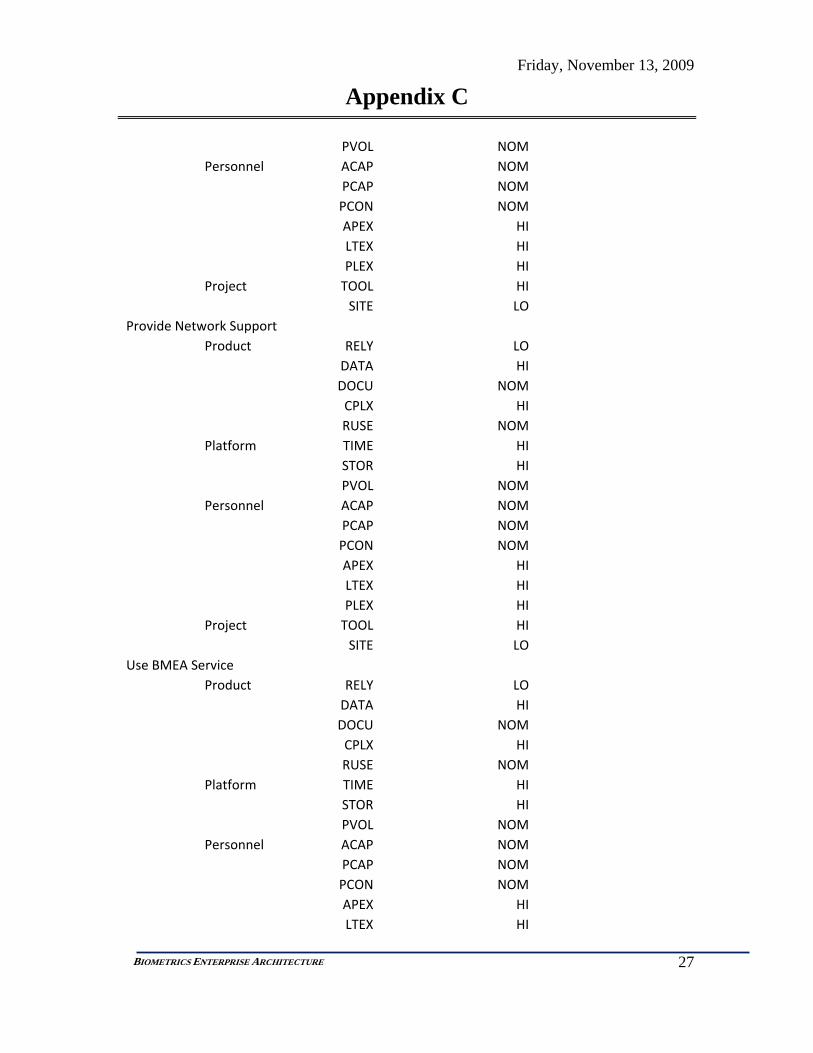
Friday, November 13, 2009
Appendix C
27
BIOMETRICS ENTERPRISE ARCHITECTURE
PVOL NOMPersonnel ACAP NOM
PCAP NOMPCON NOMAPEX HILTEX HIPLEX HI
Project TOOL HISITE LO
Provide Network Support Product RELY LO
DATA HIDOCU NOMCPLX HIRUSE NOM
Platform TIME HISTOR HIPVOL NOM
Personnel ACAP NOMPCAP NOMPCON NOMAPEX HILTEX HIPLEX HI
Project TOOL HISITE LO
Use BMEA Service Product RELY LO
DATA HIDOCU NOMCPLX HIRUSE NOM
Platform TIME HISTOR HIPVOL NOM
Personnel ACAP NOMPCAP NOMPCON NOMAPEX HILTEX HI
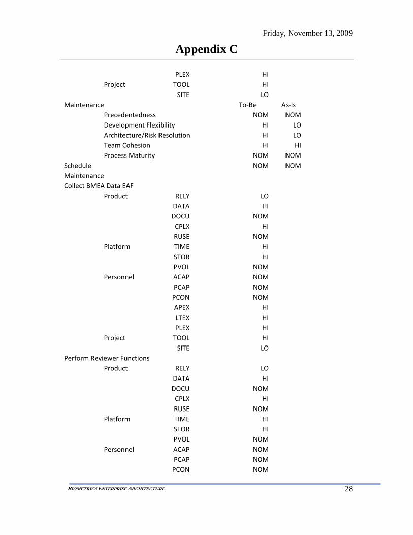
Friday, November 13, 2009
Appendix C
28
BIOMETRICS ENTERPRISE ARCHITECTURE
PLEX HIProject TOOL HI
SITE LOMaintenance To‐Be As‐Is
Precedentedness NOM NOM Development Flexibility HI LO Architecture/Risk Resolution HI LO Team Cohesion HI HI Process Maturity NOM NOM
Schedule NOM NOM Maintenance Collect BMEA Data EAF
Product RELY LODATA HIDOCU NOMCPLX HIRUSE NOM
Platform TIME HISTOR HIPVOL NOM
Personnel ACAP NOMPCAP NOMPCON NOMAPEX HILTEX HIPLEX HI
Project TOOL HISITE LO
Perform Reviewer Functions Product RELY LO
DATA HIDOCU NOMCPLX HIRUSE NOM
Platform TIME HISTOR HIPVOL NOM
Personnel ACAP NOMPCAP NOMPCON NOM

Friday, November 13, 2009
Appendix C
29
BIOMETRICS ENTERPRISE ARCHITECTURE
APEX HILTEX HIPLEX HI
Project TOOL HISITE LO
Provide Network Support Product RELY LO
DATA HIDOCU NOMCPLX HIRUSE NOM
Platform TIME HISTOR HIPVOL NOM
Personnel ACAP NOMPCAP NOMPCON NOMAPEX HILTEX HIPLEX HI
Project TOOL HISITE LO
Use BMEA Service Product RELY LO
DATA HIDOCU NOMCPLX HIRUSE NOM
Platform TIME HISTOR HIPVOL NOM
Personnel ACAP NOMPCAP NOMPCON NOMAPEX HILTEX HIPLEX HI
Project TOOL HISITE LO
Labor Rate 200 200

Friday, November 13, 2009
Appendix C
30
BIOMETRICS ENTERPRISE ARCHITECTURE
Life Span 5 5 Code Modified 10 45 Code Added 20 50 Software Unerstanding 45 20 SW Unfamiliarity 0.2 0.5

Friday, November 13, 2009
Appendix D
31
BIOMETRICS ENTERPRISE ARCHITECTURE
Appendix D. BMEA REQUIREMENTS DOCUMENT
Biometric System Enterprise Architecture (BM-EA) Functional Requirements Document
1. Introduction.
1.1. Background & Purpose. Biometric System Enterprise Architecture (BM-EA) is a system envisioned to support eased implementation and use of Biometric acquisition, search and decision capabilities across an organization’s enterprise. The enterprise consists of all parties and capabilities needed to collect, store and act on biometric images collected by biometric acquisition systems such as finger print machines. As conceptually depicted in the “BM-EA Context Diagram” below, practitioners those persons acting in the capacity as border crossing agent, who needs to quickly identify an individual crossing international borders. There is multitude other roles and activities that include the need to conduct detailed, fine-grained image analysis supporting law-enforcement forensic activities. These and multitude other activities require streamlined and economically efficient capabilities to initiate, store retrieve and compare images for assessing and adjudicating identities of individuals in support of their respective functions.
BM-EA Context Diagram
1.2. Scope. This source requirements specification establishes the basis for the design, development, performance, and test requirements for Biometric System

Friday, November 13, 2009
Appendix D
32
BIOMETRICS ENTERPRISE ARCHITECTURE
Architecture based on existing Biometric hardware systems. Biometric Enterprise Architecture (BM-EA) serves as a means for managing and using biometric information collected from biometric acquisition systems to ratify personal identification across an enterprise As depicted in the “BM-EA External Systems Diagram” below the BM-EA has four basic external “systems” or components:
• Biometric Collection Component • Subject Component • Requestor Component • The “system” represented by the BM-EA.
1.2.1. The Biometric Collection Component is represented by hardware comprised of five different biometric collection systems:
• Fingerprint Collection Machine • Iris Image Collection Machine • Facial Pattern Collection Machine • Voice Pattern Collection Machine • DNA collection capability
1.2.1.1.These hardware systems all provide an image collection capability used to supply images to the BM-EA.
1.2.2. The Requestor Component is an external actor/role that initiates biometric collection and (or) biometric verification requirements of a Subject Component. The BM-EA supports registering personal identities of individuals as well as ratifying personal identities from existing, registered identities.
1.2.3. The Subject Component is an identifiable person who is the subject of a biometric collection or verification effort conducted by a Requestor Component.

Friday, November 13, 2009
Appendix D
33
BIOMETRICS ENTERPRISE ARCHITECTURE
Figure 37 BM-EA Context Diagram
2. BM-EA Mission.
2.1. The mission of the BM-EA System is to streamline enterprise capabilities to initiate, store retrieve and compare images for assessing and adjudicating identities of individuals. BM-EA offer its users and vendors simple standardized and open architecture to develop and implement enterprise infrastructure without having to invest in redundant and repetitive capabilities when considering the use of multiple biometric collection modes. BM-EA aims to improve service availability, quality and response time and should not adversely impact a practitioner’s ability to adequately identify individuals based on their biometric signature.
3. Existing Deficiencies.
3.1. Biometric system providers currently, primarily provide BM-EA implementations as client-server based architecture and delivered systems generally involve one image mode from the modes identified above (i.e. fingerprint, voice, etc.). These system implementations are largely put into service as large, monolithic non-interoperable capabilities. Providers are driven to provide such stovepipe systems, as the underlying algorithms are largely vendor specific and are highly proprietary. As such the systems management and graphical user interface portions of the systems are tightly coupled with such delivered systems resulting in little ability to share, collate and fuse results across the various algorithm capabilities. BM EA aims to de-couple the user interface and systems management functions of the algorithms allowing vendors to focus on fine-tuning their algorithms and providing them consistent, standards based capabilities to use the results of vendor algorithm computations and calculations.
4. Related Documents.
Friday, November 13, 2009
Appendix D
34
BIOMETRICS ENTERPRISE ARCHITECTURE
• BM-EA System Source Document (this document) • EIA 632 (System Engineering Standards) • Biometric Systems Hardware Specifications • BM Book #1 • BM Book #2
5. Requirements.
5.1.General Requirements
5.1.1. A Requestor needs to collect and register biometric information of a Subject.
5.1.2. A Requestor needs to identify a Subject based on collected Biometric Information.
5.1.3. A Subject needs to use BM-EA to verify own identity to gain access to an enterprise capability.
5.2.Functional Requirements. This section describes the functional requirements of BM-EA in cascading order to the lowest level for systems design and specification. While this document specifies most of the functional capabilities required of the BM-EA as depicted in the “BM EA Functional Decomposition Diagram” below, it does not completely specify all functional requirements. What this document does accomplish is to specify functional requirements for sub-set of what BM-EA must do for a specific set of requirements and relating those requirements to user needs. Functional decomposition is used to specify and communicate broad BM-EA requirement concepts by decomposing them into layers of increasing detail resulting in a functionally specified requirements set depicted in the “BM EA Functional Decomposition Diagram”.
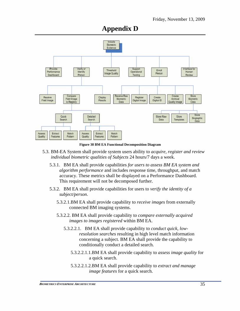
Friday, November 13, 2009
Appendix D
35
BIOMETRICS ENTERPRISE ARCHITECTURE
Figure 38 BM EA Functional Decomposition Diagram
5.3. BM-EA System shall provide system users ability to acquire, register and review individual biometric qualities of Subjects 24 hours/7 days a week.
5.3.1. BM EA shall provide capabilities for users to assess BM EA system and algorithm performance and includes response time, throughput, and match accuracy. These metrics shall be displayed on a Performance Dashboard. This requirement will not be decomposed further.
5.3.2. BM EA shall provide capabilities for users to verify the identity of a subject/person.
5.3.2.1.BM EA shall provide capability to receive images from externally connected BM imaging systems.
5.3.2.2. BM EA shall provide capability to compare externally acquired images to images registered within BM EA.
5.3.2.2.1. BM EA shall provide capability to conduct quick, low-resolution searches resulting in high level match information concerning a subject. BM EA shall provide the capability to conditionally conduct a detailed search.
5.3.2.2.1.1.BM EA shall provide capability to assess image quality for a quick search.
5.3.2.2.1.2.BM EA shall provide capability to extract and manage image features for a quick search.

Friday, November 13, 2009
Appendix D
36
BIOMETRICS ENTERPRISE ARCHITECTURE
5.3.2.2.1.3.BM EA shall provide capability to search and match selected image features for a quick search.
5.3.2.2.2. BM EA shall provide capability to conduct detailed, high-resolution searches resulting in detailed information concerning a subject.
5.3.2.2.2.1.BM EA shall provide capability to assess image quality for a detailed search.
5.3.2.2.2.2.BM EA shall provide capability to extract and manage image features for a detailed search.
5.3.2.2.2.3.BM EA shall provide capability to search and match selected image features for a detailed search.
5.3.2.3.BM EA shall provide capability to display results of comparisons from externally acquired images and images registered within BM EA.
5.3.3. BM-EA shall provide capabilities for users to assess image threshold quality. This requirement will not be decomposed further.
5.3.4. BM-EA shall provide capabilities for users to conduct and support operational testing and assessment of the BM EA capabilities. This requirement will not be decomposed further.
5.3.5. BM-EA shall provide capabilities for users to enroll subjects based on images captured from externally connected imaging systems.
5.3.5.1.BM-EA shall provide capabilities for users to induct raw biometric data into BM EA.
5.3.5.2.BM-EA shall provide capabilities for register digital biometric data into BM EA.
5.3.5.3.BM-EA shall provide capabilities for users to create Digital ID using registered images within BM EA.
5.3.5.4.BM-EA shall provide capabilities for users to create archive quality image IDs.
5.3.5.5.BM-EA shall provide capabilities for users to store and manage BM data.
5.3.5.5.1. BM-EA shall provide capabilities for users to store raw BM data.
5.3.5.5.2. BM-EA shall provide capabilities for users to create, store and manage BM templates.
5.3.5.5.3. BM-EA shall provide capabilities for users to create, store and manage BM biographic data.
Friday, November 13, 2009
Appendix D
37
BIOMETRICS ENTERPRISE ARCHITECTURE
5.3.6. BM-EA shall provide capabilities for users to engage a human reviewer/adjudicator to resolve image quality and matching issues.
5.4.BM EA shall have (at a minimum) data interactions for the following BM EA roles:
• Capture and Quality Checker • Enroller • Searcher • Tester • Performance Monitor • Offline Performance Reports • Human match result Reviewer • Poor image quality assessment Over-rider • Match Result Adjudicator
5.5.Flexibility
5.5.1. BM-EA shall support agile transaction processing allowing shifting priorities and based on perceived threat levels and performance test results
5.5.2. BM-EA shall support dynamic biometric gallery filtering and binning and fusion strategies
5.6.Scalability
5.6.1. BM-EA shall support growth or shrinkage in biometric gallery sizes of --- within --- days
5.6.2. BM-EA shall support throughput requirement increases and decreases of --- within --- days
5.7.Interoperability
5.7.1. BM-EA shall support co-location of proprietary and non-proprietary (open source) biometric match systems
5.8.Acceptability
5.8.1. BM-EA shall use only mature technology based on Fiscal Year 2012 projections
5.9.Survivability and Recoverability
5.9.1. BM-EA shall implement offline and offsite backup of all data stored within the BM-EA and shall be maintained and refreshed during each day.
5.9.2. BM-EA shall provide capability to allow data replication among geographically diverse locations for each geographical location.
5.10. Availability

Friday, November 13, 2009
Appendix D
38
BIOMETRICS ENTERPRISE ARCHITECTURE
5.10.1. BM-EA System shall provide system users ability to acquire, register and review individual biometric qualities of Subjects 24 hours/7 days a week.
5.10.2. The BM-EA shall maintain performance requirements with 99.95% availability (No greater than 4 hours per year downtime)
5.10.3. BM EA planned downtime of redundant systems shall be limited to no greater than eight (8) hours per month and scheduled for anticipated low transaction volume periods.
5.10.4. During planned downtime of redundant systems, the system must be available within one (1) hour in the event of an unplanned outage occurring elsewhere in the system
5.11. Reliability
5.11.1. During periods of availability, the BM-EA shall successfully process 99.999% of requested transactions.
5.12. Fault Tolerance
5.12.1. The BM-EA shall provide full redundancy of all mission critical components with no single point of failure at each geographical hosting center
5.12.2. The BM-EA shall maintain all minimum performance requirements despite any one (1) geographically-based event
5.13. Data Currency
5.13.1. The BM-EA shall include new biometric data for matching as soon as the data’s enrollment transaction is completed.
5.13.2. Following a geographical processing center’s downtime, recent data and transactions shall be pulled from other centers and the center’s data shall be current within 10 minutes plus 5 minutes for each hour the center’s system was unavailable.
5.14. Performance
5.14.1. The match accuracy performance of the system is very application specific and is constrained by the underling match algorithms and data quality.
5.14.2. The BM-EA match accuracy, response times, and throughput shall support business requirements above. (do we want to provide specific numbers here or leave it broad?)
5.14.3. The BM-EA shall support a flexible set of performance levels
5.14.4. The BM-EA shall support shifting priorities among match accuracy, response time, and throughput.
5.15. Capacity
Friday, November 13, 2009
Appendix D
39
BIOMETRICS ENTERPRISE ARCHITECTURE
5.15.1. The BM-EA shall initially maintain legacy biometric and associated data.
5.15.2. The BM-EA capacity shall grow dynamically with sample enrollment transactions.
5.16. Data Retention
5.16.1. All data shall be retained during natural biometric usefulness.
5.16.2. Experimental testing and life span of samples shall determine the decline in biometric usefulness due to sample aging.
5.16.3. All biometric samples shall be retained during natural biometric usefulness due to aging.
5.16.4. All data shall be archived when determined to no longer be useful in the operational biometrics.

Friday, November 13, 2009
Appendix E
40
BIOMETRICS ENTERPRISE ARCHITECTURE
Appendix E. ANALYSIS OF ALTERNATIVES (AOA)
Biometrics Architecture
Analysis of Alternatives (AOA)
To adequately consider appropriate architectural choices for enterprise Biometrics architecture, a study of the technical marketplace needs to occur in order to make an appropriate, heuristically measured choice about which architectural choice to consider from among alternatives. Our current, “As-Is” alternative, and one which is considered in this AOA, is to stay with the current client-server paradigm or architecture that the biometrics industry, in general, is currently employing. It is widely recognized that biometrics must undergo a currency transformation in order to be a viable ubiquitous capability along the lines of the telephone and similar commodity technologies. As stated in recent testimony by DHS to a Senate committee on Homeland Security7 (in part):
“…The Department is already researching emerging technologies to expand our screening and identification capabilities, and we recognize that future systems will require increased assurance, efficiency, ease of use, and flexibility.”
Collectively our group, Team Biometrics, as part of our SYSTEMS 798 project course has selected Biometric Enterprise Architecture as a topic to study and consider. As part of that effort the team needs to consider alternatives from which we will choose a favorable architecturally-based set of technologies to model in our project.
The architectural choices for Biometrics applications we are considering are the following:
• Client Server • Services Oriented Architecture (SOA) Technologies • Agent Based Technologies.
We will describe the benefits and detractors of these technologies and select the one which appears to be most favorable for our stated consideration implementation timeframe of present time to five years.
Client-Server Client Server architecture generally consists of two computer programs in which one program makes a service request from another program which fulfills the request. One end is a server, the other is a client. The client/server generally applies to computers across a network but can be applied to capabilities within a single computer; however it’s a critical distinction, most client server applications consist of two computers and a network and transactions using the client/server model are very common. Both the client and the server require deployment of software and additional hardware, in the case of biometrics, to be an effective capability for its users. Many times strings of client-server relationships are stitched together in a distributed network application supporting and
7 http://hsgac.senate.gov/public/index.cfm?FuseAction=Files.View&FileStore_id=16e8ac24-2fb2-4672-bf28-4c1e6f72113b
Friday, November 13, 2009
Appendix E
41
BIOMETRICS ENTERPRISE ARCHITECTURE
spanning large geographical areas –even supporting transactions on the other side of the globe. These transactions are structured to behave in very specific ways including ensuring and assuring that a mid-stream transaction is entered-into, transacted and completed within specified parameters including performance. These client-server oriented transactions have been used for many years and are well entrenched and ingrained in our society today.
One critical element of the client-server model in its present state is that most applications that employ it are structured and engineered for specific activities and results. This is supported by implementing strict and rigid rules for these distributed sometimes global, applications. Developers needed-to and have developed synchronous and strict rules and protocols to ensure transactional success. This made such applications highly brittle and prone to default when the transactional rules were not followed and made for slow, inefficient change and adaptation of business rules that relied on these transactions. This occurs today and is prevalent in many of the legacy applications in use now. Some applications can withstand the technology as change is minimal, or does not affect critical outcomes, but many applications including Biometrics are adversely affected by these brittle error prone communications mechanisms. For this reason, we choose not to select the prevalent and somewhat outmoded client-server model for the Biometrics Enterprise Architecture.
Services Oriented Architecture (SOA)8 Services Oriented Architecture (SOA) is an architectural framework with reference implementations where software is described as an interoperable set of services supporting some business functionality, rather than, like its client-server counterpart, an application supporting a narrowly defined business context. The primary discriminator is that software is built along business process, working or functional lines and sets of services can be composed, decomposed, and recomposed, fleetingly, to solve variety business problems –rather than building a single client-server software application that is “set-in-place” and used for only one purpose. This paradigm released the computing platform from the business context and supports wider area application of business or domain logic form places where it is traditionally employed such as the desktop. This de-coupling of business logic from computing infrastructure allows for a wider use of the domain (business) logic in a more flexible and aggressive manner. Such is the idea for Team Biometrics as we consider alternative architectures for the Biometric Enterprise. The application of services oriented concepts to the biometrics domain surely will fill gaps that currently exist and will allow more and wider flexibility in employing biometric capabilities. SOA will surely will allow wider dispersion of biometric capture facilities and centralization of critical analysis features, while allowing search algorithm providers concentrated focus on the quality of biometric search algorithms as a result of freeing those providers from the burden of needing to solve routine and typical biometric access
8 http://en.wikipedia.org/wiki/Service-oriented_architecture
Friday, November 13, 2009
Appendix E
42
BIOMETRICS ENTERPRISE ARCHITECTURE
capabilities –something which they are generally unfamiliar and uncomfortable in providing.
Agent Software A software agent is powerful way to describe a complex software entity capable of acting with a certain degree of autonomy in order to accomplish tasks on behalf of its user. The idea of a software agent supporting a Biometric Enterprise or an entity within the Biometric Enterprise is by most measures a complementary and FUTURE capability, once concepts like SOA and Cloud Computing take root. Highly available and efficient infrastructure needs to be in place in order to support agent software because of the autonomous nature they require. A high degree of infrastructure reliability and assurance is a prerequisite for large scale and widely dispersed use of software-agent technologies. For this reason, Team Biometrics is not considering software agent capabilities supporting biometrics applications at this time as out project consideration timeframe is limited to five years. Once an enterprise, supporting its biometrics requirements, makes wide-spread use of Services Oriented technology and provides robust and capable computing and communications infrastructure can that it considers using agent based capabilities supporting its biometric requirements.
Conclusion As a result of this market survey and the hierarchical relationships that exist from among the architectural choices in terms of maturity (see the Technology Curve Chart for the capabilities selected in this AOA) Team Biometrics has selected the Services Oriented Architecture to consider for this project.
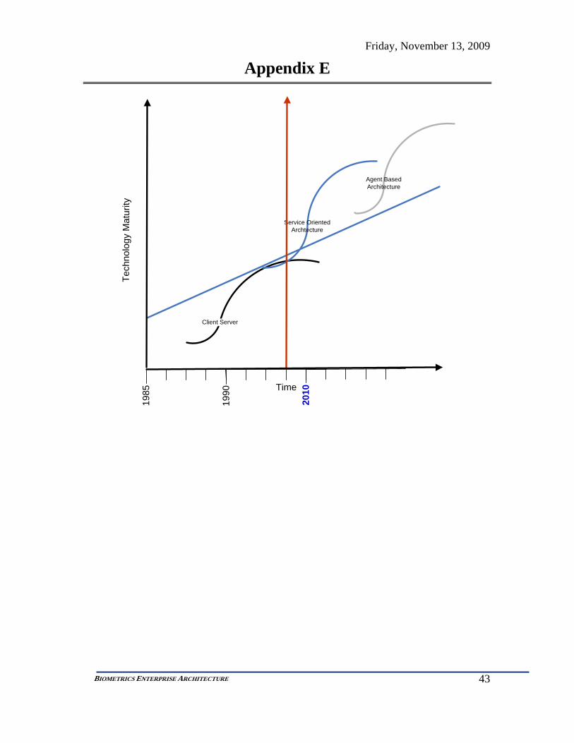
Friday, November 13, 2009
Appendix E
43
BIOMETRICS ENTERPRISE ARCHITECTURE
Client Server
Service Oriented Archtecture
Agent BasedArchitecture
1985
1990
2010Time
Tech
nolo
g y M
atur
it y

Friday, November 13, 2009
Appendix F
1
BIOMETRICS ENTERPRISE ARCHITECTURE
Appendix F. SYSTEM DESCRIPTION DOCUMENT (SDD)
SYSTEM DESCRIPTION DOCUMENT FOR
BM EA System
Thursday, December 17, 2009
Prepared For:
GMU SE/OR Faculty George Mason University
Fairfax, VA 22030
Prepared By:
Team Biometric Enterprise Architecture George Mason University
Fairfax, VA 22030

Thursday, December 17, 2009
Table of Contents
— i —
1 Component Overview ..................................................................................................................1
2 Originating Requirements ............................................................................................................6
3 Functional Behavior Model .......................................................................................................25
4 Acronyms ................................................................................... Error! Bookmark not defined.

Thursday, December 17, 2009
1 Component Overview
— 1 —
BM EA System Description:
Biometric System Enterprise Architecture (BM-EA) is a system envisioned to support eased implementation and use of Biometric acquisition, search and decision capabilities across an organization’s enterprise. The enterprise consists of all parties and capabilities needed to collect, store and act on biometric images collected by biometric acquisition systems such as finger print machines. An example of biometric practitioners would be those persons acting in the capacity of a border crossing agent, who needs to quickly identify an individual crossing international borders. There is a multitude of other roles and activities that include the need to conduct detailed, fine-grained image analysis supporting law-enforcement forensic activities. These and a multitude of other activities require streamlined and economically efficient capabilities to initiate, store retrieve and compare images for assessing and adjudicating identities of individuals in support of their respective functions.
System Mission: Biometric Enterprise Architecture (BM-EA) serves as a means for managing and using biometric information collected from biometric acquisition systems to ratify personal identification across an enterprise
Allocated Functions: 0 Provide BM-EA Services
Source Document(s): Biometrics Enterprise Architecture (BM EA) Requirements Document
Description: This source requirements specification establishes the basis for the design, development, performance, and test requirements for Biometric System Architecture based on existing Biometric hardware systems.
Inputs from External Source(s): Current Network Performance Levels
Source of Input(s): C.4 Provide Network Support
Subject External Info (Biographical Information, Documentation, Statement)
Triggers from External Source(s): Business Logic Current Threat Levels Request for Subject's BM Image QA
Source of Trigger(s): C.3 Use BM-EA Services
Request for Subject Identification/Verification Source of Trigger(s):
C.3 Use BM-EA Services
Outputs To External Destination(s): Ack that request was received and status info
Destination of Output(s): C.3 Use BM-EA Services
Border Crossing Decision Destination of Output(s):

Thursday, December 17, 2009
1 Component Overview
— 2 —
C.3 Use BM-EA Services Capacity and performance requirements
Destination of Output(s): 5 Store Data 5.7 Scale/Partition as necessary to satisfy speed requirements C.4 Provide Network Support
Communication to Law Enforcement/Intelligence Agencies/Adjudicators Enrollment Notification
Destination of Output(s): C.3 Use BM-EA Services
QA Score and Real Time Display Destination of Output(s):
C.3 Use BM-EA Services Subject ID Information
Destination of Output(s): C.3 Use BM-EA Services
built from built from built from built from built from
built from built from built from built from built from built from built from
built from built from built from built from built from built from built from built from
C
BM EA Context
Component
Ext.1
Requestor
Component
Ext.2
Image Machine
Component
Ext.3
Subject
Component
Ext.4
UnderlyingSystem Architec...
Component
SYS.1
BM EA System
Component
SYS.1.1
Requestor UserInterface Comp...
Component
SYS.1.1.1
User InterfaceMonitor Display...
Component
SYS.1.1.2
User InterfaceSW Component
Component
SYS.1.2
Image QAComponent
Component
SYS.1.3
ID RecordCreator Compo...
Component
SYS.1.4
MatchingComponent
Component
SYS.1.5
Data StorageComponent
Component
SYS.1.5.1
Raw ImageDatabase
Component
SYS.1.5.2
Data AssociationComponent
Component
SYS.1.5.3
DatabaseManager
Component
SYS.1.5.4
Data FusionComponent
Component
SYS.1.5.5
TemplateDatabase
Component
SYS.1.5.6
DatabaseStructure
Component
SYS.1.6
TesterComponent
Component
SYS.1.7
Manual Reviewer
Component
Date:Thursday, December 17, 2009
Author:University User
Number:C
Name:(University) BM EA Context
Figure 1 BM EA System Physical Context

Thursday, December 17, 2009
1 Component Overview
— 3 —
AND
C.1
Perform SubjectFunctions
C.2
Collect BM Data
0
Provide BM-EAServices
C.3
Use BM-EAServices
C.4
Provide NetworkSupport
AND
Date:Thursday, December 17, 2009
Author:University User
Number:C
Name:(University) BM EA Functional Context
Figure 2 BM EA System Functional Context

Thursday, December 17, 2009
1 Component Overview
— 4 —
Capacity andperformancerequirementsCommunicat...
C.1
Perform SubjectFunctions
CollectSubjectImage
RequestSubject to
providerequired BM
Interoperability Standards
BiometricCharacteristics of a SubjectPresent Phy...
C.2
Collect BM Data
Request tocollect BM
data
Business LogicCurrent
Threat LevelsSubject Ext...
0
Provide BM-EAServices
Request forSubject's BMImage QA
Request for...
CurrentNetwork
PerformanceLevels
RequestorNeedsSubject
External Inf...
Request forBorder
Crossing
BM Image
Ack that re...Border Cros...Enrollment ...QA Score a...
C.3
Use BM-EAServices
NetworkPolicies
Capacity andperformancerequirements
C.4
Provide NetworkSupport
Date:Thursday, December 17, 2009
Author:University User
Number:C
Name:(University) BM EA Functional Context
Figure 3 BM EA System Functional Interface Context

Thursday, December 17, 2009
1 Component Overview
— 5 —
Subject - Requestor
Adju
dica
tor
- BM
EABM
EA -
Alg
orith
m C
ente
r
Imag
e M
achi
ne -
BM
EA
Req
uest
or -
BM
EA
Ext.1
Requestor
Human
Ext.2
Image Machine
External System
Ext.3
Subject
Human
Ext.4
Underlying SystemArchitecture/Infrastructure
nil
SYS.1
BM EA System
System
Date:Thursday, December 17, 2009
Author:University User
Number:C
Name:(University) BM EA Context
Figure 4 BM EA System Physical Interface Context

Thursday, December 17, 2009
2 Originating Requirements
— 6 —
ORD.1 Use BM EA Requirement Statement:
BM-EA System shall provide system users ability to acquire, register and review individual biometric qualities of Subjects 24 hours/7 days a week.
Reference Paragraph Number & Title: 5.2 Functional Requirements
Source Document(s): Biometrics Enterprise Architecture (BM EA) Requirements Document
Refined By Subordinate Requirements: ORD.1.1 Assess Performance ORD.1.2 Verify Identity ORD.1.3 Establish Image Threshold ORD.1.4 Conduct Operational Testing ORD.1.5 Enroll Identity ORD.1.6 Engage Human Reviewer/Adjudicator
ORD.1.1 Assess Performance Requirement Statement:
BM EA shall provide capabilities for users to assess BM EA system and algorithm performance and includes response time, throughput, and match accuracy. These metrics shall be displayed on a Performance Dashboard. This requirement will not be decomposed further.
Reference Paragraph Number & Title: 5.3.1 Functional Requirements
Parent Requirement's Source Document(s): Biometrics Enterprise Architecture (BM EA) Requirements Document
Refines Higher-Level Requirement: ORD.1 Use BM EA
ORD.1.2 Verify Identity Requirement Statement:
BM EA shall provide capabilities for users to verify the identity of a subject/person.
Reference Paragraph Number & Title: 5.3.2 Functional Requirements
Parent Requirement's Source Document(s): Biometrics Enterprise Architecture (BM EA) Requirements Document
Refines Higher-Level Requirement: ORD.1 Use BM EA
Refined By Subordinate Requirements: ORD.1.2.1 Receive Images ORD.1.2.2 Compare External Images ORD.1.2.3 Display Comparison Result

Thursday, December 17, 2009
2 Originating Requirements
— 7 —
ORD.1.2.1 Receive Images Requirement Statement:
BM EA shall provide capability to receive images from externally connected BM imaging systems.
Reference Paragraph Number & Title: 5.3.2.1 Verify Identity
Parent Requirement's Source Document(s): Biometrics Enterprise Architecture (BM EA) Requirements Document
Refines Higher-Level Requirement: ORD.1.2 Verify Identity
ORD.1.2.2 Compare External Images Requirement Statement:
BM EA shall provide capability to compare externally acquired images to images registered within BM EA.
Reference Paragraph Number & Title: 5.3.2.2 Verify Identity
Parent Requirement's Source Document(s): Biometrics Enterprise Architecture (BM EA) Requirements Document
Refines Higher-Level Requirement: ORD.1.2 Verify Identity
Refined By Subordinate Requirements: ORD.1.2.2.1 Conduct Quick Low Resolution Search ORD.1.2.2.2 Conduct Detailed High Resolution Search
ORD.1.2.2.1 Conduct Quick Low Resolution Search Requirement Statement:
BM EA shall provide capability to conduct quick, low-resolution searches resulting in high level match information concerning a subject. BM EA shall provide the capability to conditionally conduct a detailed search.
Reference Paragraph Number & Title: 5.3.2.2 Verify Identity
Parent Requirement's Source Document(s): Biometrics Enterprise Architecture (BM EA) Requirements Document
Refines Higher-Level Requirement: ORD.1.2.2 Compare External Images
Refined By Subordinate Requirements: ORD.1.2.2.1.1 Asses Image Quality Quick Search ORD.1.2.2.1.2 Extract Image Features Quick Search ORD.1.2.2.1.3 Manage Image Features ORD.1.2.2.1.4 Search Selected Image Features ORD.1.2.2.1.5 Match Selected Image Features

Thursday, December 17, 2009
2 Originating Requirements
— 8 —
ORD.1.2.2.1.1 Asses Image Quality Quick Search Requirement Statement:
BM EA shall provide capability to assess image quality for a quick search.
Reference Paragraph Number & Title: 5.3.2.2.1.3 Verify Identity
Parent Requirement's Source Document(s): Biometrics Enterprise Architecture (BM EA) Requirements Document
Refines Higher-Level Requirement: ORD.1.2.2.1 Conduct Quick Low Resolution Search
ORD.1.2.2.1.2 Extract Image Features Quick Search Requirement Statement:
BM EA shall provide capability to extract and manage image features for a quick search.
Reference Paragraph Number & Title: 5.3.2.2.1.2 Verify Identity
Parent Requirement's Source Document(s): Biometrics Enterprise Architecture (BM EA) Requirements Document
Refines Higher-Level Requirement: ORD.1.2.2.1 Conduct Quick Low Resolution Search
ORD.1.2.2.1.3 Manage Image Features Requirement Statement:
BM EA shall provide capability to extract and manage image features for a quick search.
Reference Paragraph Number & Title: 5.3.2.2.1.2 Verify Identity
Parent Requirement's Source Document(s): Biometrics Enterprise Architecture (BM EA) Requirements Document
Refines Higher-Level Requirement: ORD.1.2.2.1 Conduct Quick Low Resolution Search
ORD.1.2.2.1.4 Search Selected Image Features Requirement Statement:
BM EA shall provide capability to search selected image features for a quick search.
Reference Paragraph Number & Title: 5.3.2.2.1.3 Verify Identity
Parent Requirement's Source Document(s): Biometrics Enterprise Architecture (BM EA) Requirements Document
Refines Higher-Level Requirement: ORD.1.2.2.1 Conduct Quick Low Resolution Search

Thursday, December 17, 2009
2 Originating Requirements
— 9 —
ORD.1.2.2.1.5 Match Selected Image Features Requirement Statement:
BM EA shall provide capability to match selected image features for a quick search.
Reference Paragraph Number & Title: 5.3.2.2.1.3 Verify Identity
Parent Requirement's Source Document(s): Biometrics Enterprise Architecture (BM EA) Requirements Document
Refines Higher-Level Requirement: ORD.1.2.2.1 Conduct Quick Low Resolution Search
ORD.1.2.2.2 Conduct Detailed High Resolution Search Requirement Statement:
BM EA shall provide capability to conduct detailed, high-resolution searches resulting in detailed information concerning a subject.
Reference Paragraph Number & Title: 5.3.2.2.2 Verify Identity
Parent Requirement's Source Document(s): Biometrics Enterprise Architecture (BM EA) Requirements Document
Refines Higher-Level Requirement: ORD.1.2.2 Compare External Images
Refined By Subordinate Requirements: ORD.1.2.2.2.1 Assess Image Quality Detailed Search ORD.1.2.2.2.2 Extract Image Features Detailed Search ORD.1.2.2.2.3 Manage Image Features Detailed Search ORD.1.2.2.2.4 Search Image Features Detailed Search ORD.1.2.2.2.5 Match Image Features Detailed Search
ORD.1.2.2.2.1 Assess Image Quality Detailed Search Requirement Statement:
BM EA shall provide capability to assess image quality for a detailed search.
Reference Paragraph Number & Title: 5.3.2.2.2.1 Verify Identity
Parent Requirement's Source Document(s): Biometrics Enterprise Architecture (BM EA) Requirements Document
Refines Higher-Level Requirement: ORD.1.2.2.2 Conduct Detailed High Resolution Search
ORD.1.2.2.2.2 Extract Image Features Detailed Search Requirement Statement:
BM EA shall provide capability to extract and manage image features for a detailed search.
Reference Paragraph Number & Title:

Thursday, December 17, 2009
2 Originating Requirements
— 10 —
5.3.2.2.2.2 Verify Identity
Parent Requirement's Source Document(s): Biometrics Enterprise Architecture (BM EA) Requirements Document
Refines Higher-Level Requirement: ORD.1.2.2.2 Conduct Detailed High Resolution Search
ORD.1.2.2.2.3 Manage Image Features Detailed Search Requirement Statement:
BM EA shall provide capability to extract and manage image features for a detailed search.
Reference Paragraph Number & Title: 5.3.2.2.2.2 Verify Identity
Parent Requirement's Source Document(s): Biometrics Enterprise Architecture (BM EA) Requirements Document
Refines Higher-Level Requirement: ORD.1.2.2.2 Conduct Detailed High Resolution Search
ORD.1.2.2.2.4 Search Image Features Detailed Search Requirement Statement:
BM EA shall provide capability to search selected image features for a detailed search.
Reference Paragraph Number & Title: 5.3.2.2.2.3 Verify Identity
Parent Requirement's Source Document(s): Biometrics Enterprise Architecture (BM EA) Requirements Document
Refines Higher-Level Requirement: ORD.1.2.2.2 Conduct Detailed High Resolution Search
ORD.1.2.2.2.5 Match Image Features Detailed Search Requirement Statement:
BM EA shall provide capability to match selected image features for a detailed search.
Reference Paragraph Number & Title: 5.3.2.2.2.3 Verify Identity
Parent Requirement's Source Document(s): Biometrics Enterprise Architecture (BM EA) Requirements Document
Refines Higher-Level Requirement: ORD.1.2.2.2 Conduct Detailed High Resolution Search
ORD.1.2.3 Display Comparison Result Requirement Statement:
BM EA shall provide capability to display results of comparisons from externally acquired images and images registered within BM EA.

Thursday, December 17, 2009
2 Originating Requirements
— 11 —
Reference Paragraph Number & Title: 5.3.2.3 Verify Identity
Parent Requirement's Source Document(s): Biometrics Enterprise Architecture (BM EA) Requirements Document
Refines Higher-Level Requirement: ORD.1.2 Verify Identity
ORD.1.3 Establish Image Threshold Requirement Statement:
BM-EA shall provide capabilities for users to assess image threshold quality. This requirement will not be decomposed further.
Reference Paragraph Number & Title: 5.3.3 Use BM EA
Parent Requirement's Source Document(s): Biometrics Enterprise Architecture (BM EA) Requirements Document
Refines Higher-Level Requirement: ORD.1 Use BM EA
ORD.1.4 Conduct Operational Testing Requirement Statement:
BM-EA shall provide capabilities for users to conduct and support operational testing and assessment of the BM EA capabilities. This requirement will not be decomposed further.
Reference Paragraph Number & Title: 5.3.4 Use BM EA
Parent Requirement's Source Document(s): Biometrics Enterprise Architecture (BM EA) Requirements Document
Refines Higher-Level Requirement: ORD.1 Use BM EA
ORD.1.5 Enroll Identity Requirement Statement:
BM-EA shall provide capabilities for users to enroll subjects based on images captured from externally connected imaging systems.
Reference Paragraph Number & Title: 5.3.5 Use BM EA
Parent Requirement's Source Document(s): Biometrics Enterprise Architecture (BM EA) Requirements Document
Refines Higher-Level Requirement: ORD.1 Use BM EA
Refined By Subordinate Requirements: ORD.1.5.1 Induct Raw Biometric Data

Thursday, December 17, 2009
2 Originating Requirements
— 12 —
ORD.1.5.2 Register Digital Biometrtic Data ORD.1.5.3 Create Digital ID ORD.1.5.4 Create Arrchive Quality Image IDs. ORD.1.5.5 Store and Manage Biometric Data
Specifies: Component: SYS.1 BM EA System
ORD.1.5.1 Induct Raw Biometric Data Requirement Statement:
BM-EA shall provide capabilities for users to induct raw biometric data into BM EA.
Reference Paragraph Number & Title: 5.3.5.1 Enroll Identity
Parent Requirement's Source Document(s): Biometrics Enterprise Architecture (BM EA) Requirements Document
Refines Higher-Level Requirement: ORD.1.5 Enroll Identity
ORD.1.5.2 Register Digital Biometrtic Data Requirement Statement:
BM-EA shall provide capabilities for register digital biometric data into BM EA.
Reference Paragraph Number & Title: 5.3.5.2 Enroll Identity
Parent Requirement's Source Document(s): Biometrics Enterprise Architecture (BM EA) Requirements Document
Refines Higher-Level Requirement: ORD.1.5 Enroll Identity
ORD.1.5.3 Create Digital ID Requirement Statement:
BM-EA shall provide capabilities for users to create Digital ID using registered images within BM EA.
Reference Paragraph Number & Title: 5.3.5.3 Enroll Identity
Parent Requirement's Source Document(s): Biometrics Enterprise Architecture (BM EA) Requirements Document
Refines Higher-Level Requirement: ORD.1.5 Enroll Identity
ORD.1.5.4 Create Arrchive Quality Image IDs. Requirement Statement:
BM-EA shall provide capabilities for users to create archive quality image IDs.

Thursday, December 17, 2009
2 Originating Requirements
— 13 —
Reference Paragraph Number & Title: 5.3.5.4 Enroll Identity
Parent Requirement's Source Document(s): Biometrics Enterprise Architecture (BM EA) Requirements Document
Refines Higher-Level Requirement: ORD.1.5 Enroll Identity
ORD.1.5.5 Store and Manage Biometric Data Requirement Statement:
BM-EA shall provide capabilities for users to store and manage BM data.
Reference Paragraph Number & Title: 5.3.5.5 Enroll Identity
Parent Requirement's Source Document(s): Biometrics Enterprise Architecture (BM EA) Requirements Document
Refines Higher-Level Requirement: ORD.1.5 Enroll Identity
Refined By Subordinate Requirements: ORD.1.5.5.1 Store Raw Biometric Data ORD.1.5.5.2 Use Biometric Templates ORD.1.5.5.3 Use Biometric Biographic Data
ORD.1.5.5.1 Store Raw Biometric Data Requirement Statement:
BM-EA shall provide capabilities for users to store raw BM data.
Reference Paragraph Number & Title: 5.3.5.5.1 Enroll Identity
Parent Requirement's Source Document(s): Biometrics Enterprise Architecture (BM EA) Requirements Document
Refines Higher-Level Requirement: ORD.1.5.5 Store and Manage Biometric Data
ORD.1.5.5.2 Use Biometric Templates Requirement Statement:
BM-EA shall provide capabilities for users to create, store and manage BM templates.
Reference Paragraph Number & Title: 5.3.5.5.2 Enroll Identity
Parent Requirement's Source Document(s): Biometrics Enterprise Architecture (BM EA) Requirements Document
Refines Higher-Level Requirement: ORD.1.5.5 Store and Manage Biometric Data

Thursday, December 17, 2009
2 Originating Requirements
— 14 —
ORD.1.5.5.3 Use Biometric Biographic Data Requirement Statement:
BM-EA shall provide capabilities for users to create, store and manage BM biographic data.
Reference Paragraph Number & Title: 5.3.5.5.3 Enroll Identity
Parent Requirement's Source Document(s): Biometrics Enterprise Architecture (BM EA) Requirements Document
Refines Higher-Level Requirement: ORD.1.5.5 Store and Manage Biometric Data
ORD.1.6 Engage Human Reviewer/Adjudicator Requirement Statement:
BM-EA shall provide capabilities for users to engage a human reviewer/adjudicator to resolve image quality and matching issues.
Reference Paragraph Number & Title: 5.3.5 Use BM EA
Parent Requirement's Source Document(s): Biometrics Enterprise Architecture (BM EA) Requirements Document
Refines Higher-Level Requirement: ORD.1 Use BM EA
ORD.2 Conduct Systems Management Requirement Statement:
BM EA shall have (at a minimum) data interactions for the following BM EA roles: • Capture and Quality Checker • Enroller • Searcher • Tester • Performance Monitor • Offline Performance Reports • Human match result Reviewer • Poor image quality assessment Over-rider • Match Result Adjudicator
Reference Paragraph Number & Title: 5.4 Use BM EA
Source Document(s): Biometrics Enterprise Architecture (BM EA) Requirements Document
ORD.3 Flexibility Reference Paragraph Number & Title:
5.5 Flexibility
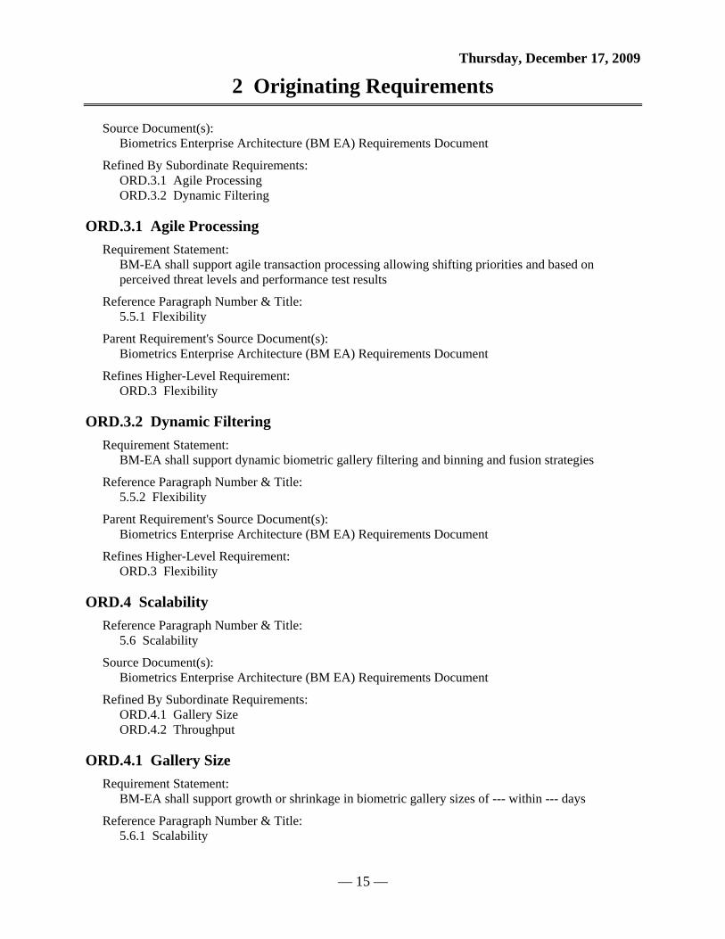
Thursday, December 17, 2009
2 Originating Requirements
— 15 —
Source Document(s): Biometrics Enterprise Architecture (BM EA) Requirements Document
Refined By Subordinate Requirements: ORD.3.1 Agile Processing ORD.3.2 Dynamic Filtering
ORD.3.1 Agile Processing Requirement Statement:
BM-EA shall support agile transaction processing allowing shifting priorities and based on perceived threat levels and performance test results
Reference Paragraph Number & Title: 5.5.1 Flexibility
Parent Requirement's Source Document(s): Biometrics Enterprise Architecture (BM EA) Requirements Document
Refines Higher-Level Requirement: ORD.3 Flexibility
ORD.3.2 Dynamic Filtering Requirement Statement:
BM-EA shall support dynamic biometric gallery filtering and binning and fusion strategies
Reference Paragraph Number & Title: 5.5.2 Flexibility
Parent Requirement's Source Document(s): Biometrics Enterprise Architecture (BM EA) Requirements Document
Refines Higher-Level Requirement: ORD.3 Flexibility
ORD.4 Scalability Reference Paragraph Number & Title:
5.6 Scalability
Source Document(s): Biometrics Enterprise Architecture (BM EA) Requirements Document
Refined By Subordinate Requirements: ORD.4.1 Gallery Size ORD.4.2 Throughput
ORD.4.1 Gallery Size Requirement Statement:
BM-EA shall support growth or shrinkage in biometric gallery sizes of --- within --- days
Reference Paragraph Number & Title: 5.6.1 Scalability

Thursday, December 17, 2009
2 Originating Requirements
— 16 —
Parent Requirement's Source Document(s): Biometrics Enterprise Architecture (BM EA) Requirements Document
Refines Higher-Level Requirement: ORD.4 Scalability
ORD.4.2 Throughput Requirement Statement:
BM-EA shall support throughput requirement increases and decreases of --- within --- days
Reference Paragraph Number & Title: 5.6.2 Scalability
Parent Requirement's Source Document(s): Biometrics Enterprise Architecture (BM EA) Requirements Document
Refines Higher-Level Requirement: ORD.4 Scalability
ORD.5 Interoperability Reference Paragraph Number & Title:
5.7 Interoperability
Source Document(s): Biometrics Enterprise Architecture (BM EA) Requirements Document
Refined By Subordinate Requirements: ORD.5.1 Co-Location
ORD.5.1 Co-Location Requirement Statement:
BM-EA shall support co-location of proprietary and non-proprietary (open source) biometric match systems
Reference Paragraph Number & Title: 5.7.1 Interoperability
Parent Requirement's Source Document(s): Biometrics Enterprise Architecture (BM EA) Requirements Document
Refines Higher-Level Requirement: ORD.5 Interoperability
ORD.6 Acceptability Reference Paragraph Number & Title:
5.8 Acceptability
Source Document(s): Biometrics Enterprise Architecture (BM EA) Requirements Document
Refined By Subordinate Requirements: ORD.6.1 Technology
Thursday, December 17, 2009
2 Originating Requirements
— 17 —
ORD.6.1 Technology Requirement Statement:
BM-EA shall use only mature technology based on Fiscal Year 2012 projections
Reference Paragraph Number & Title: 5.8.1 Acceptability
Parent Requirement's Source Document(s): Biometrics Enterprise Architecture (BM EA) Requirements Document
Refines Higher-Level Requirement: ORD.6 Acceptability
ORD.7 Survivability and Recoverability Reference Paragraph Number & Title:
5.9 Survivability and Recoverability
Source Document(s): Biometrics Enterprise Architecture (BM EA) Requirements Document
Refined By Subordinate Requirements: ORD.7.1 Data Backup ORD.7.2 Data Replication
ORD.7.1 Data Backup Requirement Statement:
BM-EA shall implement offline and offsite backup of all data stored within the BM-EA and shall be maintained and refreshed during each day.
Reference Paragraph Number & Title: 5.9.1 Survivability and Recoverability
Parent Requirement's Source Document(s): Biometrics Enterprise Architecture (BM EA) Requirements Document
Refines Higher-Level Requirement: ORD.7 Survivability and Recoverability
ORD.7.2 Data Replication Requirement Statement:
BM-EA shall provide capability to allow data replication among geographically diverse locations for each geographical location.
Reference Paragraph Number & Title: 5.9.2 Survivability and Recoverability
Parent Requirement's Source Document(s): Biometrics Enterprise Architecture (BM EA) Requirements Document
Refines Higher-Level Requirement: ORD.7 Survivability and Recoverability

Thursday, December 17, 2009
2 Originating Requirements
— 18 —
ORD.8 Availability Reference Paragraph Number & Title:
5.10 Availability
Source Document(s): Biometrics Enterprise Architecture (BM EA) Requirements Document
Refined By Subordinate Requirements: ORD.8.1 User Abilities ORD.8.2 Maintain Performance ORD.8.3 Planned Downtime ORD.8.4 Availability during Downtime
ORD.8.1 User Abilities Requirement Statement:
BM-EA System shall provide system users ability to acquire, register and review individual biometric qualities of Subjects 24 hours/7 days a week.
Reference Paragraph Number & Title: 5.10.1 Availability
Parent Requirement's Source Document(s): Biometrics Enterprise Architecture (BM EA) Requirements Document
Refines Higher-Level Requirement: ORD.8 Availability
ORD.8.2 Maintain Performance Requirement Statement:
The BM-EA shall maintain performance requirements with 99.95% availability (No greater than 4 hours per year downtime)
Reference Paragraph Number & Title: 5.10.2 Availability
Parent Requirement's Source Document(s): Biometrics Enterprise Architecture (BM EA) Requirements Document
Refines Higher-Level Requirement: ORD.8 Availability
ORD.8.3 Planned Downtime Requirement Statement:
BM EA planned downtime of redundant systems shall be limited to no greater than eight (8) hours per month and scheduled for anticipated low transaction volume periods.
Reference Paragraph Number & Title: 5.10.3 Availability
Parent Requirement's Source Document(s): Biometrics Enterprise Architecture (BM EA) Requirements Document

Thursday, December 17, 2009
2 Originating Requirements
— 19 —
Refines Higher-Level Requirement: ORD.8 Availability
ORD.8.4 Availability during Downtime Requirement Statement:
During planned downtime of redundant systems, the system must be available within one (1) hour in the event of an unplanned outage occurring elsewhere in the system
Reference Paragraph Number & Title: 5.10.4 Availability
Parent Requirement's Source Document(s): Biometrics Enterprise Architecture (BM EA) Requirements Document
Refines Higher-Level Requirement: ORD.8 Availability
ORD.9 Reliability Reference Paragraph Number & Title:
5.11 Reliability
Source Document(s): Biometrics Enterprise Architecture (BM EA) Requirements Document
Refined By Subordinate Requirements: ORD.9.1 Percentage to Process
ORD.10 Fault Tolerance Reference Paragraph Number & Title:
5.12 Fault Tolerance
Source Document(s): Biometrics Enterprise Architecture (BM EA) Requirements Document
Refined By Subordinate Requirements: ORD.10.1 Full Redundancy ORD.10.2 Maintain Min Performance
ORD.10.1 Full Redundancy Requirement Statement:
The BM-EA shall provide full redundancy of all mission critical components with no single point of failure at each geographical hosting center
Reference Paragraph Number & Title: 5.12.1 Fault Tolerance
Parent Requirement's Source Document(s): Biometrics Enterprise Architecture (BM EA) Requirements Document
Refines Higher-Level Requirement: ORD.10 Fault Tolerance

Thursday, December 17, 2009
2 Originating Requirements
— 20 —
ORD.10.2 Maintain Min Performance Requirement Statement:
The BM-EA shall maintain all minimum performance requirements despite any one (1) geographically-based event
Reference Paragraph Number & Title: 5.12.2 Fault Tolerance
Parent Requirement's Source Document(s): Biometrics Enterprise Architecture (BM EA) Requirements Document
Refines Higher-Level Requirement: ORD.10 Fault Tolerance
ORD.11 Data Currency Reference Paragraph Number & Title:
5.13 Data Currency
Source Document(s): Biometrics Enterprise Architecture (BM EA) Requirements Document
Refined By Subordinate Requirements: ORD.11.1 New BM data ORD.11.2 Pulling Recent Data
ORD.11.1 New BM data Requirement Statement:
The BM-EA shall include new biometric data for matching as soon as the data’s enrollment transaction is completed.
Reference Paragraph Number & Title: 5.13.1 Data Currency
Parent Requirement's Source Document(s): Biometrics Enterprise Architecture (BM EA) Requirements Document
Refines Higher-Level Requirement: ORD.11 Data Currency
ORD.11.2 Pulling Recent Data Requirement Statement:
Following a geographical processing center’s downtime, recent data and transactions shall be pulled from other centers and the center’s data shall be current within 10 minutes plus 5 minutes for each hour the center’s system was unavailable.
Reference Paragraph Number & Title: 5.13.2 Data Currency
Parent Requirement's Source Document(s): Biometrics Enterprise Architecture (BM EA) Requirements Document
Refines Higher-Level Requirement:
Thursday, December 17, 2009
2 Originating Requirements
— 21 —
ORD.11 Data Currency
ORD.12 Performance Reference Paragraph Number & Title:
5.14 Performance
Source Document(s): Biometrics Enterprise Architecture (BM EA) Requirements Document
Refined By Subordinate Requirements: ORD.12.1 Match Accuracy ORD.12.2 Support Bus Requirements ORD.12.3 Flexible Perf Levels ORD.12.4 Shifting Priorities
ORD.12.1 Match Accuracy Requirement Statement:
The match accuracy performance of the system is very application specific and is constrained by the underling match algorithms and data quality.
Reference Paragraph Number & Title: 5.14.1 Performance
Parent Requirement's Source Document(s): Biometrics Enterprise Architecture (BM EA) Requirements Document
Refines Higher-Level Requirement: ORD.12 Performance
ORD.12.2 Support Bus Requirements Requirement Statement:
The BM-EA match accuracy, response times, and throughput shall support business requirements above.
Reference Paragraph Number & Title: 5.14.2 Performance
Parent Requirement's Source Document(s): Biometrics Enterprise Architecture (BM EA) Requirements Document
Refines Higher-Level Requirement: ORD.12 Performance
ORD.12.3 Flexible Perf Levels Requirement Statement:
The BM-EA shall support a flexible set of performance levels
Reference Paragraph Number & Title: 5.14.3 Performance
Parent Requirement's Source Document(s):

Thursday, December 17, 2009
2 Originating Requirements
— 22 —
Biometrics Enterprise Architecture (BM EA) Requirements Document
Refines Higher-Level Requirement: ORD.12 Performance
ORD.12.4 Shifting Priorities Requirement Statement:
The BM-EA shall support shifting priorities among match accuracy, response time, and throughput.
Reference Paragraph Number & Title: 5.14.4 Performance
Parent Requirement's Source Document(s): Biometrics Enterprise Architecture (BM EA) Requirements Document
Refines Higher-Level Requirement: ORD.12 Performance
ORD.13 Capacity Reference Paragraph Number & Title:
5.15 Capacity
Source Document(s): Biometrics Enterprise Architecture (BM EA) Requirements Document
Refined By Subordinate Requirements: ORD.13.1 Legacy Data ORD.13.2 Dynamic Growth
ORD.13.1 Legacy Data Requirement Statement:
The BM-EA shall initially maintain legacy biometric and associated data.
Reference Paragraph Number & Title: 5.15.1 Capacity
Parent Requirement's Source Document(s): Biometrics Enterprise Architecture (BM EA) Requirements Document
Refines Higher-Level Requirement: ORD.13 Capacity
ORD.13.2 Dynamic Growth Requirement Statement:
The BM-EA capacity shall grow dynamically with sample enrollment transactions.
Reference Paragraph Number & Title: 5.15.2 Capacity
Parent Requirement's Source Document(s): Biometrics Enterprise Architecture (BM EA) Requirements Document
Thursday, December 17, 2009
2 Originating Requirements
— 23 —
Refines Higher-Level Requirement: ORD.13 Capacity
ORD.14 Data Retention Reference Paragraph Number & Title:
5.16 Data Retention
Source Document(s): Biometrics Enterprise Architecture (BM EA) Requirements Document
Refined By Subordinate Requirements: ORD.14.1 Retain Data ORD.14.2 Experimental Testing ORD.14.3 Biometric Samples ORD.14.4 Data Archival
ORD.14.1 Retain Data Requirement Statement:
All data shall be retained during natural biometric usefulness.
Reference Paragraph Number & Title: 5.16.1 Data Retention
Parent Requirement's Source Document(s): Biometrics Enterprise Architecture (BM EA) Requirements Document
Refines Higher-Level Requirement: ORD.14 Data Retention
ORD.14.2 Experimental Testing Requirement Statement:
Experimental testing and life span of samples shall determine the decline in biometric usefulness due to sample aging.
Reference Paragraph Number & Title: 5.16.2 Data Retention
Parent Requirement's Source Document(s): Biometrics Enterprise Architecture (BM EA) Requirements Document
Refines Higher-Level Requirement: ORD.14 Data Retention
ORD.14.3 Biometric Samples Requirement Statement:
All biometric samples shall be retained during natural biometric usefulness due to aging.
Reference Paragraph Number & Title: 5.16.3 Data Retention
Parent Requirement's Source Document(s):

Thursday, December 17, 2009
2 Originating Requirements
— 24 —
Biometrics Enterprise Architecture (BM EA) Requirements Document
Refines Higher-Level Requirement: ORD.14 Data Retention
ORD.14.4 Data Archival Requirement Statement:
All data shall be archived when determined to no longer be useful in the operational biometrics.
Reference Paragraph Number & Title: 5.16.4 Data Retention
Parent Requirement's Source Document(s): Biometrics Enterprise Architecture (BM EA) Requirements Document
Refines Higher-Level Requirement: ORD.14 Data Retention

Thursday, December 17, 2009
4 Acronyms
— 25 —
Part I - Hierarchical Function List 0 Provide BM-EA Services 1 Accept Requests and Provide Feedback 1.1 Process Requests 1.2 Display Status Information 1.3 Display Real Time Image QA Score 1.4 Display Subject's Identity as determined from BM-EA 1.5 Notify Requestor to allow/disallow border crossing 1.6 Notify Requestor that Subject is to be enrolled in BM-EA 2 Assess Image Quality 2.1 Accept Request for Image Quality Assessment 2.2 Execute Quality Assessement 2.3 Generate a QA Score 3 Create Subject ID Record 3.1 Accept Request for Subject ID/Verification 3.2 Assess Risk Level of Transaction 3.3 Process Requests based on Risk/Priority Level 3.4 Enhance Raw Image 3.5 Extract Features 3.6 Assess Quality 3.7 Generate Template 4 Conduct Search For Matches 4.1 Receive Subject's Newly Created Template 4.2 Determine Transaction Type (Fingerprint, Facial, Iris, etc.) 4.3 Access Stored BM Templates from Database for Comparison 4.4 Allocate additional processing time for high risk transactions 4.5 Select Pattern Matching Algorithm 4.6 Compare New Template to Stored Templates 4.7 Perform Additional Comparison with more accurate PM Algorithm 4.8 Determine the Number of Matches 5 Store Data 5.1 Store Raw Image Data 5.2 Associate raw image data with corresponding template 5.3 Input additional biographic info to complete template 5.4 Search Database for other BM modality info related to Subject 5.5 Fuse fingerprint, iris, facial, voice data for all entries 5.6 Store BM Templates/Subject ID Record 5.7 Scale/Partition as necessary to satisfy speed requirements

Thursday, December 17, 2009
4 Acronyms
— 26 —
6 Conduct Performance Tests 6.1 Identify niche Algorithms for specific transaction types 6.2 Process hypothetical transactions under different threat levels 6.3 Relay capacity/performance requirements to the network infrastructure 7 Perform Reviewer Functions 7.1 Analyze and Compare Match results to subject template 7.2 Verify Identity of Subject 7.3 Determine if Subject's Identity requires notification to law enforcement 7.4 Notify requestor to allow/disallow border crossing 7.5 Notify requestor that subject is to be enrolled in BM-EA 7.6 Forward Template to database magager for enrollment
Part II - Behavior Model
0 Provide BM-EA Services Description:
The BM EA system shall perform functions necessary to allow requestors to establish-in or ascertain-from a persons (a subject's) identity based on as-collected or from pre-collected bimoetric infomration.
Allocated To: SYS.1 BM EA System
Table 1 0 Provide BM-EA Services Interfacing Items Interfacing Items Source / Destination
Ack that request was received and status info Input To: C.3 Use BM-EA Services
Output From: 0 Provide BM-EA Services 1 Accept Requests and Provide Feedback 1.2 Display Status Information
Border Crossing Decision Input To: C.3 Use BM-EA Services
Output From: 0 Provide BM-EA Services 1 Accept Requests and Provide Feedback 1.5 Notify Requestor to allow/disallow border crossing
Business Logic Triggers Function(s): 0 Provide BM-EA Services 7 Perform Reviewer Functions 7.1 Analyze and Compare Match results to subject template 7.2 Verify Identity of Subject

Thursday, December 17, 2009
4 Acronyms
— 27 —
Table 1 0 Provide BM-EA Services Interfacing Items Interfacing Items Source / Destination
7.3 Determine if Subject's Identity requires notification to law enforcement 7.4 Notify requestor to allow/disallow border crossing7.5 Notify requestor that subject is to be enrolled in BM-EA C BM EA Functional Context
Capacity and performance requirements Input To: 5 Store Data 5.7 Scale/Partition as necessary to satisfy speed requirements C.4 Provide Network Support
Output From: 0 Provide BM-EA Services 6 Conduct Performance Tests 6.3 Relay capacity/performance requirements to the network infrastructure
Communication to Law Enforcement/Intelligence Agencies/Adjudicators
Output From: 0 Provide BM-EA Services 7 Perform Reviewer Functions 7.3 Determine if Subject's Identity requires notification to law enforcement C BM EA Functional Context
Current Network Performance Levels Input To: 0 Provide BM-EA Services 6 Conduct Performance Tests 6.1 Identify niche Algorithms for specific transaction types 6.2 Process hypothetical transactions under different threat levels 6.3 Relay capacity/performance requirements to the network infrastructure
Output From: C.4 Provide Network Support
Current Threat Levels Triggers Function(s): 0 Provide BM-EA Services 3 Create Subject ID Record 3.2 Assess Risk Level of Transaction 3.3 Process Requests based on Risk/Priority Level 4 Conduct Search For Matches 4.4 Allocate additional processing time for high risk transactions 4.5 Select Pattern Matching Algorithm 4.6 Compare New Template to Stored Templates

Thursday, December 17, 2009
4 Acronyms
— 28 —
Table 1 0 Provide BM-EA Services Interfacing Items Interfacing Items Source / Destination
4.7 Perform Additional Comparison with more accurate PM Algorithm 4.8 Determine the Number of Matches C BM EA Functional Context
Enrollment Notification Input To: C.3 Use BM-EA Services
Output From: 0 Provide BM-EA Services 1 Accept Requests and Provide Feedback 1.6 Notify Requestor that Subject is to be enrolled in BM-EA
QA Score and Real Time Display Input To: C.3 Use BM-EA Services
Output From: 0 Provide BM-EA Services 1 Accept Requests and Provide Feedback 1.3 Display Real Time Image QA Score
Request for Subject's BM Image QA Triggers Function(s): 0 Provide BM-EA Services 1 Accept Requests and Provide Feedback 1.1 Process Requests
Output From: C.3 Use BM-EA Services
Request for Subject Identification/Verification Triggers Function(s): 0 Provide BM-EA Services 1 Accept Requests and Provide Feedback 1.1 Process Requests
Output From: C.3 Use BM-EA Services
Subject External Info (Biographical Information, Documentation, Statement)
Input To: 0 Provide BM-EA Services 3 Create Subject ID Record 3.7 Generate Template C BM EA Functional Context C.3 Use BM-EA Services
Subject ID Information Input To: C.3 Use BM-EA Services
Output From: 0 Provide BM-EA Services 1 Accept Requests and Provide Feedback 1.4 Display Subject's Identity as determined from BM-EA

Thursday, December 17, 2009
4 Acronyms
— 29 —
BM-EA Optimization
Raw Image Quality Check
Data Archival
Attempt to Find a BM Match
1
Accept Requestsand ProvideFeedback
AND
2
Assess ImageQuality
3
Create SubjectID Record
4
Conduct SearchFor Matches
5
Store Data
6
ConductPerformance
Tests
AND
7
PerformReviewerFunctions
Subject'sIdentity
Real TimeQA Scoring
Notificationthat Subj...
Decision toallow/disal...
RequestImage Re...
EnrollmentNotification
QA Scoreand Real ...
Subject IDInformation
BorderCrossing ...
DigitizedRequest f...
DigitizedRequest f...
Ack thatrequest ...
Requestfor Subjec...
Requestfor Subjec...
Raw ImageData
SubjectExternal I...
NewlyCreated ...
RiskAssessme...
CurrentThreat Le...
Stored BMTemplates
Notificationof No Mat...
Top matchresults
Capacityand perf...
NewTemplate ...
CurrentNetwork ...
Communication to Law...
BusinessLogic
Date:Thursday, December 17, 2009
Author:University User
Number:0
Name:(University) Provide BM-EA Services
Figure 5 Provide BM-EA Services Enhanced FFBD

Thursday, December 17, 2009
4 Acronyms
— 30 —
BM-EA Optimization
Raw Image Quality Check
Data Archival
Attempt to Find a BM Match
Ref.
1
Accept Requestsand ProvideFeedback
AND
2
Assess ImageQuality
3
Create SubjectID Record
4
Conduct SearchFor Matches
5
Store Data
6
ConductPerformance
Tests
AND
7
PerformReviewerFunctions
C.3
Use BM-EAServices
Date:Thursday, December 17, 2009
Author:University User
Number:0
Name:(University) Provide BM-EA Services
Figure 6 Provide BM-EA Services FFBD

Thursday, December 17, 2009
4 Acronyms
— 31 —
Ack that re...Border Cros...Enrollment ...QA Score a...
Raw ImageData
RiskAssessment
ofTransaction
Top matchresults
Capacity andperformancerequirements
Communication to Law
Enforcemen...Subject's Id...
Request forSubject's BMImage QA
Request for...
1
Accept Requestsand ProvideFeedback
Real Time QAScoring
RequestImage
Recollectionif determined...
Decision toallow/disallo...Notification ...Subject's Id...
DigitizedRequest for
BM Image QA
2
Assess ImageQuality
CurrentThreat Levels
SubjectExternal Inf...
DigitizedRequest for
SubjectID/Verification
Raw ImageData
3
Create SubjectID Record
CurrentThreat Levels
NewlyCreated
Subject BM ...Risk Asses...
4
Conduct SearchFor Matches
Stored BMTemplates
Capacity andperformancerequirements
Raw ImageData
5
Store Data
Capacity andperformancerequirements
NewTemplate to
Enroll
CurrentNetwork
PerformanceLevels
6
ConductPerformance
Tests
Business Logic
NewlyCreated
Subject BMTemplate
Notificationof No
Matches Fo...Top match r...
7
PerformReviewerFunctions
Date:Thursday, December 17, 2009
Author:University User
Number:0
Name:(University) Provide BM-EA Services
Figure 7 Provide BM-EA Services N2 Diagram

Thursday, December 17, 2009
4 Acronyms
— 32 —
BM EA System
Data Storage ComponentID Record Creator Component
Raw Image Data
Capacity and performance requirements
Business Logic
Border Crossing Decision
Image QA Component
Manual Reviewer
Matching ComponentRequestor User Interface Component Tester Component
Ack that request was received and status info
Newly Created Subject BM Template
Capacity and performance requirements
Top match results
Subject ID Information
Subject External Info (Biographical Information, Documentation, Statement)
Subject's Identity
Stored BM Templates
Risk Assessment of Transaction
Request Image Recollection if determined insufficient
Request for Subject Identification/VerificationRequest for Subject's BM Image QA
Real Time QA Sco...
Raw Image Data
QA Score and Real Time Display
Notification that Subject is to be Enrolled
Notification of No Matches Found
Newly Created Subject BM Template
New Template to Enroll
Enrollment NotificationDigitized Request for Subject ID/VerificationDigitized Request for BM Image QA
Decision to allow/disallow border crossing
Current Threat Levels
Current Network Performance Levels
Communication to Law Enforcement/Intelligence Agencies/Adjudicators
1
Accept Requestsand ProvideFeedback
2
Assess ImageQuality
3
Create SubjectID Record
4
Conduct SearchFor Matches
5
Store Data
6
ConductPerformance
Tests
7
PerformReviewerFunctions
Date:Thursday, December 17, 2009
Author:University User
Number:0
Name:(University) Provide BM-EA Services
Figure 8 Provide BM-EA Services IDEF0 Diagram
1 Accept Requests and Provide Feedback Description:
BM-EA will accept requests from an external user (Requestor Role) and provide Feedback.
Allocated To: SYS.1.1 Requestor User Interface Component
Table 2 1 Accept Requests and Provide Feedback Interfacing Items Interfacing Items Source / Destination
Ack that request was received and status info Input To: C.3 Use BM-EA Services
Output From: 0 Provide BM-EA Services 1 Accept Requests and Provide Feedback 1.2 Display Status Information
Border Crossing Decision Input To: C.3 Use BM-EA Services
Output From: 0 Provide BM-EA Services 1 Accept Requests and Provide Feedback 1.5 Notify Requestor to allow/disallow border crossing

Thursday, December 17, 2009
4 Acronyms
— 33 —
Table 2 1 Accept Requests and Provide Feedback Interfacing Items Interfacing Items Source / Destination
Decision to allow/disallow border crossing Input To: 1 Accept Requests and Provide Feedback 1.5 Notify Requestor to allow/disallow border crossing
Output From: 7 Perform Reviewer Functions 7.4 Notify requestor to allow/disallow border crossing
Digitized Request for BM Image QA Triggers Function(s): 2 Assess Image Quality 2.1 Accept Request for Image Quality Assessment
Output From: 1 Accept Requests and Provide Feedback 1.1 Process Requests
Digitized Request for Subject ID/Verification Triggers Function(s): 3 Create Subject ID Record 3.1 Accept Request for Subject ID/Verification
Output From: 1 Accept Requests and Provide Feedback 1.1 Process Requests
Enrollment Notification Input To: C.3 Use BM-EA Services
Output From: 0 Provide BM-EA Services 1 Accept Requests and Provide Feedback 1.6 Notify Requestor that Subject is to be enrolled in BM-EA
Notification that Subject is to be Enrolled Input To: 1 Accept Requests and Provide Feedback 1.6 Notify Requestor that Subject is to be enrolled in BM-EA
Output From: 7 Perform Reviewer Functions 7.5 Notify requestor that subject is to be enrolled in BM-EA
QA Score and Real Time Display Input To: C.3 Use BM-EA Services
Output From: 0 Provide BM-EA Services 1 Accept Requests and Provide Feedback 1.3 Display Real Time Image QA Score
Real Time QA Scoring Input To:

Thursday, December 17, 2009
4 Acronyms
— 34 —
Table 2 1 Accept Requests and Provide Feedback Interfacing Items Interfacing Items Source / Destination
1 Accept Requests and Provide Feedback 1.3 Display Real Time Image QA Score
Output From: 2 Assess Image Quality 2.3 Generate a QA Score
Request for Subject's BM Image QA Triggers Function(s): 0 Provide BM-EA Services 1 Accept Requests and Provide Feedback 1.1 Process Requests
Output From: C.3 Use BM-EA Services
Request for Subject Identification/Verification Triggers Function(s): 0 Provide BM-EA Services 1 Accept Requests and Provide Feedback 1.1 Process Requests
Output From: C.3 Use BM-EA Services
Request Image Recollection if determined insufficient Input To: 1 Accept Requests and Provide Feedback 1.2 Display Status Information
Output From: 3 Create Subject ID Record 3.6 Assess Quality
Subject's Identity Input To: 1 Accept Requests and Provide Feedback 1.4 Display Subject's Identity as determined from BM-EA
Triggers Function(s): 7.3 Determine if Subject's Identity requires notification to law enforcement 7.4 Notify requestor to allow/disallow border crossing
Output From: 7 Perform Reviewer Functions 7.2 Verify Identity of Subject
Subject ID Information Input To: C.3 Use BM-EA Services
Output From: 0 Provide BM-EA Services 1 Accept Requests and Provide Feedback 1.4 Display Subject's Identity as determined from BM-EA
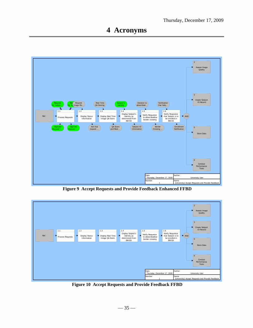
Thursday, December 17, 2009
4 Acronyms
— 35 —
Ref.
1.1
Process Requests
1.2
Display StatusInformation
1.3
Display Real TimeImage QA Score
1.4Display Subject's
Identity asdetermined from
BM-EA
1.5
Notify Requestorto allow/disallowborder crossing
1.6Notify Requestorthat Subject is to
be enrolled inBM-EA
AND
2
Assess ImageQuality
3
Create SubjectID Record
5
Store Data
6
ConductPerformance
Tests
DigitizedRequest f...
DigitizedRequest f...
Requestfor Subjec...
Requestfor Subjec...
RequestImage Re...
Ack thatrequest ...
Real TimeQA Scoring
QA Scoreand Real ...
Subject'sIdentity
Subject IDInformation
Decision toallow/disal...
BorderCrossing ...
Notificationthat Subj...
EnrollmentNotification
Date:Thursday, December 17, 2009
Author:University User
Number:1
Name:(University) Accept Requests and Provide Feedback
Figure 9 Accept Requests and Provide Feedback Enhanced FFBD
Ref.
1.1
Process Requests
1.2
Display StatusInformation
1.3
Display Real TimeImage QA Score
1.4Display Subject's
Identity asdetermined from
BM-EA
1.5
Notify Requestorto allow/disallowborder crossing
1.6Notify Requestorthat Subject is to
be enrolled inBM-EA
AND
2
Assess ImageQuality
3
Create SubjectID Record
5
Store Data
6
ConductPerformance
Tests
Date:Thursday, December 17, 2009
Author:University User
Number:1
Name:(University) Accept Requests and Provide Feedback
Figure 10 Accept Requests and Provide Feedback FFBD

Thursday, December 17, 2009
4 Acronyms
— 36 —
DigitizedRequest for
BM Image QADigitized Re...
Ack thatrequest wasreceived andstatus info
QA Scoreand Real
Time Display
Subject IDInformation
BorderCrossingDecision
EnrollmentNotification
Request forSubject's BMImage QA
Request for...
1.1
Process Requests
RequestImage
Recollectionif determined...
1.2
Display StatusInformation
Real Time QAScoring
1.3
Display Real TimeImage QA Score
Subject'sIdentity
1.4
Display Subject'sIdentity as
determined fromBM-EA
Decision toallow/disallow
bordercrossing
1.5
Notify Requestorto allow/disallowborder crossing
Notificationthat Subject
is to beEnrolled
1.6
Notify Requestorthat Subject is to
be enrolled inBM-EA
Date:Thursday, December 17, 2009
Author:University User
Number:1
Name:(University) Accept Requests and Provide Feedback
Figure 11 Accept Requests and Provide Feedback N2 Diagram

Thursday, December 17, 2009
4 Acronyms
— 37 —
Subject IDInformation
Subject'sIdentity
Request ImageRecollection ifdeterminedinsufficient
Request forSubjectIdentification/Verification
Request forSubject's BMImage QA
Real TimeQA Scoring
QA Score andReal Time Display
Notificationthat Subjectis to beEnrolled
EnrollmentNotification
Digitized Request forSubject ID/VerificationDigitized Request for BM Image QA
Decision toallow/disallowborder crossing
BorderCrossingDecision
Ack thatrequest wasreceived andstatus info
User InterfaceMonitor DisplayComponent
Requestor UserInterfaceComponent
User InterfaceMonitor DisplayComponent
User InterfaceMonitor DisplayComponent
User InterfaceMonitor DisplayComponent
User InterfaceMonitor DisplayComponent
User InterfaceSW Component
1.1
Process Requests
1.2
Display StatusInformation
1.3
Display Real TimeImage QA Score
1.4Display Subject's
Identity asdetermined from
BM-EA
1.5
Notify Requestorto allow/disallowborder crossing
1.6Notify Requestorthat Subject is to
be enrolled inBM-EA
Date:Thursday, December 17, 2009
Author:University User
Number:1
Name:(University) Accept Requests and Provide Feedback
Figure 12 Accept Requests and Provide Feedback IDEF0 Diagram
1.1 Process Requests Description:
User requests will be processed accordingly.
Allocated To: SYS.1.1.2 User Interface SW Component
Table 3 1.1 Process Requests Interfacing Items Interfacing Items Source / Destination
Digitized Request for BM Image QA Triggers Function(s): 2 Assess Image Quality 2.1 Accept Request for Image Quality Assessment
Output From: 1 Accept Requests and Provide Feedback 1.1 Process Requests

Thursday, December 17, 2009
4 Acronyms
— 38 —
Table 3 1.1 Process Requests Interfacing Items Interfacing Items Source / Destination
Digitized Request for Subject ID/Verification Triggers Function(s): 3 Create Subject ID Record 3.1 Accept Request for Subject ID/Verification
Output From: 1 Accept Requests and Provide Feedback 1.1 Process Requests
Request for Subject's BM Image QA Triggers Function(s): 0 Provide BM-EA Services 1 Accept Requests and Provide Feedback 1.1 Process Requests
Output From: C.3 Use BM-EA Services
Request for Subject Identification/Verification Triggers Function(s): 0 Provide BM-EA Services 1 Accept Requests and Provide Feedback 1.1 Process Requests
Output From: C.3 Use BM-EA Services
1.2 Display Status Information Description:
Status of requests will be displayed to inform the user.
Allocated To: SYS.1.1.1 User Interface Monitor Display Component
Table 4 1.2 Display Status Information Interfacing Items Interfacing Items Source / Destination
Ack that request was received and status info Input To: C.3 Use BM-EA Services
Output From: 0 Provide BM-EA Services 1 Accept Requests and Provide Feedback 1.2 Display Status Information
Request Image Recollection if determined insufficient Input To: 1 Accept Requests and Provide Feedback 1.2 Display Status Information
Output From: 3 Create Subject ID Record 3.6 Assess Quality
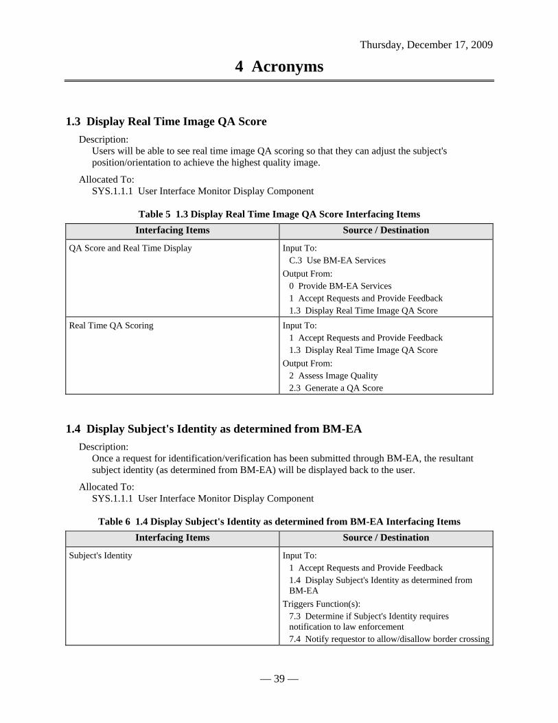
Thursday, December 17, 2009
4 Acronyms
— 39 —
1.3 Display Real Time Image QA Score Description:
Users will be able to see real time image QA scoring so that they can adjust the subject's position/orientation to achieve the highest quality image.
Allocated To: SYS.1.1.1 User Interface Monitor Display Component
Table 5 1.3 Display Real Time Image QA Score Interfacing Items Interfacing Items Source / Destination
QA Score and Real Time Display Input To: C.3 Use BM-EA Services
Output From: 0 Provide BM-EA Services 1 Accept Requests and Provide Feedback 1.3 Display Real Time Image QA Score
Real Time QA Scoring Input To: 1 Accept Requests and Provide Feedback 1.3 Display Real Time Image QA Score
Output From: 2 Assess Image Quality 2.3 Generate a QA Score
1.4 Display Subject's Identity as determined from BM-EA Description:
Once a request for identification/verification has been submitted through BM-EA, the resultant subject identity (as determined from BM-EA) will be displayed back to the user.
Allocated To: SYS.1.1.1 User Interface Monitor Display Component
Table 6 1.4 Display Subject's Identity as determined from BM-EA Interfacing Items Interfacing Items Source / Destination
Subject's Identity Input To: 1 Accept Requests and Provide Feedback 1.4 Display Subject's Identity as determined from BM-EA
Triggers Function(s): 7.3 Determine if Subject's Identity requires notification to law enforcement 7.4 Notify requestor to allow/disallow border crossing
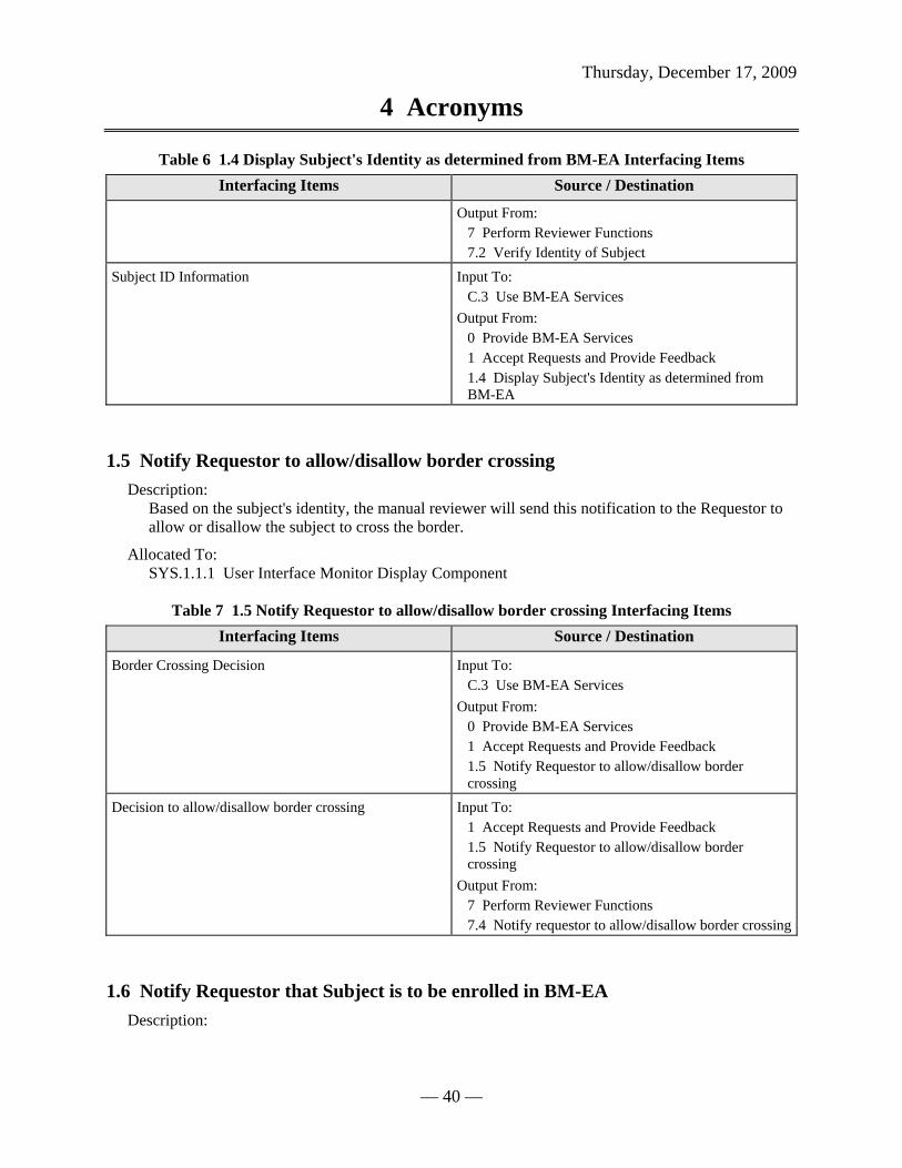
Thursday, December 17, 2009
4 Acronyms
— 40 —
Table 6 1.4 Display Subject's Identity as determined from BM-EA Interfacing Items Interfacing Items Source / Destination
Output From: 7 Perform Reviewer Functions 7.2 Verify Identity of Subject
Subject ID Information Input To: C.3 Use BM-EA Services
Output From: 0 Provide BM-EA Services 1 Accept Requests and Provide Feedback 1.4 Display Subject's Identity as determined from BM-EA
1.5 Notify Requestor to allow/disallow border crossing Description:
Based on the subject's identity, the manual reviewer will send this notification to the Requestor to allow or disallow the subject to cross the border.
Allocated To: SYS.1.1.1 User Interface Monitor Display Component
Table 7 1.5 Notify Requestor to allow/disallow border crossing Interfacing Items Interfacing Items Source / Destination
Border Crossing Decision Input To: C.3 Use BM-EA Services
Output From: 0 Provide BM-EA Services 1 Accept Requests and Provide Feedback 1.5 Notify Requestor to allow/disallow border crossing
Decision to allow/disallow border crossing Input To: 1 Accept Requests and Provide Feedback 1.5 Notify Requestor to allow/disallow border crossing
Output From: 7 Perform Reviewer Functions 7.4 Notify requestor to allow/disallow border crossing
1.6 Notify Requestor that Subject is to be enrolled in BM-EA Description:

Thursday, December 17, 2009
4 Acronyms
— 41 —
If it is determined that the subject does not currently have a stored identification record in the BM-EA database, then the manual reviewer will inform the requestor that the subject is to be enrolled into BM-EA.
Allocated To: SYS.1.1.1 User Interface Monitor Display Component Table 8 1.6 Notify Requestor that Subject is to be enrolled in BM-EA Interfacing Items
Interfacing Items Source / Destination
Enrollment Notification Input To: C.3 Use BM-EA Services
Output From: 0 Provide BM-EA Services 1 Accept Requests and Provide Feedback 1.6 Notify Requestor that Subject is to be enrolled in BM-EA
Notification that Subject is to be Enrolled Input To: 1 Accept Requests and Provide Feedback 1.6 Notify Requestor that Subject is to be enrolled in BM-EA
Output From: 7 Perform Reviewer Functions 7.5 Notify requestor that subject is to be enrolled in BM-EA
2 Assess Image Quality Description:
BM-EA will assess the raw image quality of a particular biometric provided by a human subject.
Allocated To: SYS.1.2 Image QA Component
Table 9 2 Assess Image Quality Interfacing Items Interfacing Items Source / Destination
Digitized Request for BM Image QA Triggers Function(s): 2 Assess Image Quality 2.1 Accept Request for Image Quality Assessment
Output From: 1 Accept Requests and Provide Feedback 1.1 Process Requests
Raw Image Data Input To: 3 Create Subject ID Record 3.4 Enhance Raw Image 5 Store Data
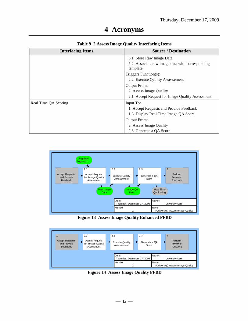
Thursday, December 17, 2009
4 Acronyms
— 42 —
Table 9 2 Assess Image Quality Interfacing Items Interfacing Items Source / Destination
5.1 Store Raw Image Data 5.2 Associate raw image data with corresponding template
Triggers Function(s): 2.2 Execute Quality Assessement
Output From: 2 Assess Image Quality 2.1 Accept Request for Image Quality Assessment
Real Time QA Scoring Input To: 1 Accept Requests and Provide Feedback 1.3 Display Real Time Image QA Score
Output From: 2 Assess Image Quality 2.3 Generate a QA Score
1
Accept Requestsand ProvideFeedback
2.1
Accept Requestfor Image Quality
Assessment
2.2
Execute QualityAssessement
2.3
Generate a QAScore
7
PerformReviewerFunctions
Raw ImageData
DigitizedRequest f...
Image QAData
Real TimeQA Scoring
Date:Thursday, December 17, 2009
Author:University User
Number:2
Name:(University) Assess Image Quality
Figure 13 Assess Image Quality Enhanced FFBD
1
Accept Requestsand ProvideFeedback
2.1
Accept Requestfor Image Quality
Assessment
2.2
Execute QualityAssessement
2.3
Generate a QAScore
7
PerformReviewerFunctions
Date:Thursday, December 17, 2009
Author:University User
Number:2
Name:(University) Assess Image Quality
Figure 14 Assess Image Quality FFBD

Thursday, December 17, 2009
4 Acronyms
— 43 —
Raw ImageData
Real Time QAScoring
DigitizedRequest for
BM Image QA
2.1
Accept Requestfor Image Quality
Assessment
Raw ImageData
Raw ImageData
2.2
Execute QualityAssessement
Image QAData
2.3
Generate a QAScore
Date:Thursday, December 17, 2009
Author:University User
Number:2
Name:(University) Assess Image Quality
Figure 15 Assess Image Quality N2 Diagram

Thursday, December 17, 2009
4 Acronyms
— 44 —
Real Time QA Scoring
Image QA Component
Raw Image DataRaw Image Data
DigitizedRequest for BMImage QA
Image QA Data
2.1
Accept Requestfor Image Quality
Assessment
2.2
Execute QualityAssessement
2.3
Generate a QAScore
Date:Thursday, December 17, 2009
Author:University User
Number:2
Name:(University) Assess Image Quality
Figure 16 Assess Image Quality IDEF0 Diagram
2.1 Accept Request for Image Quality Assessment Description:
Requests for an Image QA will be accepted.
Allocated To: SYS.1.2 Image QA Component
Table 10 2.1 Accept Request for Image Quality Assessment Interfacing Items Interfacing Items Source / Destination
Digitized Request for BM Image QA Triggers Function(s): 2 Assess Image Quality 2.1 Accept Request for Image Quality Assessment
Output From: 1 Accept Requests and Provide Feedback 1.1 Process Requests

Thursday, December 17, 2009
4 Acronyms
— 45 —
Table 10 2.1 Accept Request for Image Quality Assessment Interfacing Items Interfacing Items Source / Destination
Raw Image Data Input To: 3 Create Subject ID Record 3.4 Enhance Raw Image 5 Store Data 5.1 Store Raw Image Data 5.2 Associate raw image data with corresponding template
Triggers Function(s): 2.2 Execute Quality Assessement
Output From: 2 Assess Image Quality 2.1 Accept Request for Image Quality Assessment
2.2 Execute Quality Assessement Description:
A quality assessment of the raw image will be executed.
Allocated To: SYS.1.2 Image QA Component
Table 11 2.2 Execute Quality Assessement Interfacing Items Interfacing Items Source / Destination
Image QA Data Triggers Function(s): 2.3 Generate a QA Score
Output From: 2.2 Execute Quality Assessement
Raw Image Data Input To: 3 Create Subject ID Record 3.4 Enhance Raw Image 5 Store Data 5.1 Store Raw Image Data 5.2 Associate raw image data with corresponding template
Triggers Function(s): 2.2 Execute Quality Assessement
Output From: 2 Assess Image Quality 2.1 Accept Request for Image Quality Assessment

Thursday, December 17, 2009
4 Acronyms
— 46 —
2.3 Generate a QA Score Description:
The result of the execution of the QA is score indicating the level of quality of the raw image.
Allocated To: SYS.1.2 Image QA Component
Table 12 2.3 Generate a QA Score Interfacing Items Interfacing Items Source / Destination
Image QA Data Triggers Function(s): 2.3 Generate a QA Score
Output From: 2.2 Execute Quality Assessement
Real Time QA Scoring Input To: 1 Accept Requests and Provide Feedback 1.3 Display Real Time Image QA Score
Output From: 2 Assess Image Quality 2.3 Generate a QA Score
3 Create Subject ID Record Description:
BM-EA will create an identification record (biometric template) for each subject who submits a biometric sample to BM-EA.
Allocated To: SYS.1.3 ID Record Creator Component
Table 13 3 Create Subject ID Record Interfacing Items Interfacing Items Source / Destination
Current Threat Levels Triggers Function(s): 0 Provide BM-EA Services 3 Create Subject ID Record 3.2 Assess Risk Level of Transaction 3.3 Process Requests based on Risk/Priority Level 4 Conduct Search For Matches 4.4 Allocate additional processing time for high risk transactions 4.5 Select Pattern Matching Algorithm 4.6 Compare New Template to Stored Templates 4.7 Perform Additional Comparison with more accurate PM Algorithm 4.8 Determine the Number of Matches

Thursday, December 17, 2009
4 Acronyms
— 47 —
Table 13 3 Create Subject ID Record Interfacing Items Interfacing Items Source / Destination
C BM EA Functional Context Digitized Request for Subject ID/Verification Triggers Function(s):
3 Create Subject ID Record 3.1 Accept Request for Subject ID/Verification
Output From: 1 Accept Requests and Provide Feedback 1.1 Process Requests
Newly Created Subject BM Template Input To: 4 Conduct Search For Matches 4.1 Receive Subject's Newly Created Template 7 Perform Reviewer Functions 7.1 Analyze and Compare Match results to subject template 7.6 Forward Template to database magager for enrollment
Output From: 3 Create Subject ID Record 3.7 Generate Template
Raw Image Data Input To: 3 Create Subject ID Record 3.4 Enhance Raw Image 5 Store Data 5.1 Store Raw Image Data 5.2 Associate raw image data with corresponding template
Triggers Function(s): 2.2 Execute Quality Assessement
Output From: 2 Assess Image Quality 2.1 Accept Request for Image Quality Assessment
Request Image Recollection if determined insufficient Input To: 1 Accept Requests and Provide Feedback 1.2 Display Status Information
Output From: 3 Create Subject ID Record 3.6 Assess Quality
Risk Assessment of Transaction Triggers Function(s): 3.3 Process Requests based on Risk/Priority Level 4 Conduct Search For Matches 4.4 Allocate additional processing time for high risk transactions 4.5 Select Pattern Matching Algorithm

Thursday, December 17, 2009
4 Acronyms
— 48 —
Table 13 3 Create Subject ID Record Interfacing Items Interfacing Items Source / Destination
Output From: 3 Create Subject ID Record 3.2 Assess Risk Level of Transaction
Subject External Info (Biographical Information, Documentation, Statement)
Input To: 0 Provide BM-EA Services 3 Create Subject ID Record 3.7 Generate Template C BM EA Functional Context C.3 Use BM-EA Services
1
Accept Requestsand ProvideFeedback
3.1
Accept Requestfor Subject
ID/Verification
3.2
Assess Risk Levelof Transaction
3.3
Process Requestsbased on
Risk/Priority Level
3.4
Enhance RawImage
3.5
Extract Features
3.6
Assess Quality
3.7
GenerateTemplate
4
Conduct SearchFor Matches
RequestInformation
DigitizedRequest f...
RiskAssessme...
CurrentThreat Le...
ProcessedRequests
Raw ImageData
EnhancedImage Features Quality OK
RequestImage Re...
SubjectExternal I...
NewlyCreated ...
Date:Thursday, December 17, 2009
Author:University User
Number:3
Name:(University) Create Subject ID Record
Figure 17 Create Subject ID Record Enhanced FFBD
1
Accept Requestsand ProvideFeedback
3.1
Accept Requestfor Subject
ID/Verification
3.2
Assess Risk Levelof Transaction
3.3
Process Requestsbased on
Risk/Priority Level
3.4
Enhance RawImage
3.5
Extract Features
3.6
Assess Quality
3.7
GenerateTemplate
4
Conduct SearchFor Matches
Date:Thursday, December 17, 2009
Author:University User
Number:3
Name:(University) Create Subject ID Record
Figure 18 Create Subject ID Record FFBD

Thursday, December 17, 2009
4 Acronyms
— 49 —
RiskAssessment
ofTransaction
RequestImage
Recollectionif determined...
NewlyCreated
Subject BMTemplate
DigitizedRequest for
SubjectID/Verification
3.1
Accept Requestfor Subject
ID/Verification
CurrentThreat Levels
RequestInformation
3.2
Assess Risk Levelof Transaction
CurrentThreat Levels
RiskAssessment...
RiskAssessment
ofTransaction
3.3
Process Requestsbased on
Risk/Priority Level
Raw ImageData
ProcessedRequests
3.4
Enhance RawImage
EnhancedImage
3.5
Extract Features Features
3.6
Assess Quality
SubjectExternal Info(BiographicalInformation...
Features
Quality OK
3.7
GenerateTemplate
Date:Thursday, December 17, 2009
Author:University User
Number:3
Name:(University) Create Subject ID Record
Figure 19 Create Subject ID Record N2 Diagram

Thursday, December 17, 2009
4 Acronyms
— 50 —
Risk Assessment of Transaction
Request Information
Risk Assessment of Transaction
Subject External Info(Biographical Information,Documentation, Statement)
Request ImageRecollection ifdeterminedinsufficient
Raw Image Data
Quality OK
Features
Processed Requests
Newly CreatedSubject BMTemplate
Features
Enhanced Image
Digitized Request for Subject ID/Verification Current Threat Levels
ID Record Creator Component
3.1
Accept Requestfor Subject
ID/Verification
3.2
Assess Risk Levelof Transaction
3.3
Process Requestsbased on
Risk/Priority Level
3.4
Enhance RawImage
3.5
Extract Features
3.6
Assess Quality
3.7
GenerateTemplate
Date:Thursday, December 17, 2009
Author:University User
Number:3
Name:(University) Create Subject ID Record
Figure 20 Create Subject ID Record IDEF0 Diagram
3.1 Accept Request for Subject ID/Verification Description:
The request for Subject ID/Verification along with raw image will be accepted.
Allocated To: SYS.1.3 ID Record Creator Component
Table 14 3.1 Accept Request for Subject ID/Verification Interfacing Items Interfacing Items Source / Destination
Digitized Request for Subject ID/Verification Triggers Function(s): 3 Create Subject ID Record 3.1 Accept Request for Subject ID/Verification
Output From: 1 Accept Requests and Provide Feedback 1.1 Process Requests
Request Information Triggers Function(s): 3.2 Assess Risk Level of Transaction

Thursday, December 17, 2009
4 Acronyms
— 51 —
Table 14 3.1 Accept Request for Subject ID/Verification Interfacing Items Interfacing Items Source / Destination
Output From: 3.1 Accept Request for Subject ID/Verification
3.2 Assess Risk Level of Transaction Description:
A risk level will be assessed to the transaction based on several factors such as current threat levels as a result of recent terrorist activity, or the geographic location of where the transaction is taking place.
Allocated To: SYS.1.3 ID Record Creator Component
Table 15 3.2 Assess Risk Level of Transaction Interfacing Items Interfacing Items Source / Destination
Current Threat Levels Triggers Function(s): 0 Provide BM-EA Services 3 Create Subject ID Record 3.2 Assess Risk Level of Transaction 3.3 Process Requests based on Risk/Priority Level 4 Conduct Search For Matches 4.4 Allocate additional processing time for high risk transactions 4.5 Select Pattern Matching Algorithm 4.6 Compare New Template to Stored Templates 4.7 Perform Additional Comparison with more accurate PM Algorithm 4.8 Determine the Number of Matches C BM EA Functional Context
Request Information Triggers Function(s): 3.2 Assess Risk Level of Transaction
Output From: 3.1 Accept Request for Subject ID/Verification
Risk Assessment of Transaction Triggers Function(s): 3.3 Process Requests based on Risk/Priority Level 4 Conduct Search For Matches 4.4 Allocate additional processing time for high risk transactions 4.5 Select Pattern Matching Algorithm
Output From: 3 Create Subject ID Record 3.2 Assess Risk Level of Transaction

Thursday, December 17, 2009
4 Acronyms
— 52 —
3.3 Process Requests based on Risk/Priority Level Description:
Requests will be processed based on their risk/priority level.
Allocated To: SYS.1.3 ID Record Creator Component
Table 16 3.3 Process Requests based on Risk/Priority Level Interfacing Items Interfacing Items Source / Destination
Current Threat Levels Triggers Function(s): 0 Provide BM-EA Services 3 Create Subject ID Record 3.2 Assess Risk Level of Transaction 3.3 Process Requests based on Risk/Priority Level 4 Conduct Search For Matches 4.4 Allocate additional processing time for high risk transactions 4.5 Select Pattern Matching Algorithm 4.6 Compare New Template to Stored Templates 4.7 Perform Additional Comparison with more accurate PM Algorithm 4.8 Determine the Number of Matches C BM EA Functional Context
Processed Requests Triggers Function(s): 3.4 Enhance Raw Image
Output From: 3.3 Process Requests based on Risk/Priority Level
Risk Assessment of Transaction Triggers Function(s): 3.3 Process Requests based on Risk/Priority Level 4 Conduct Search For Matches 4.4 Allocate additional processing time for high risk transactions 4.5 Select Pattern Matching Algorithm
Output From: 3 Create Subject ID Record 3.2 Assess Risk Level of Transaction
3.4 Enhance Raw Image Description:
The raw image is enhanced using some image enhancement algorithm.
Allocated To:

Thursday, December 17, 2009
4 Acronyms
— 53 —
SYS.1.3 ID Record Creator Component
Table 17 3.4 Enhance Raw Image Interfacing Items Interfacing Items Source / Destination
Enhanced Image Triggers Function(s): 3.5 Extract Features
Output From: 3.4 Enhance Raw Image
Processed Requests Triggers Function(s): 3.4 Enhance Raw Image
Output From: 3.3 Process Requests based on Risk/Priority Level
Raw Image Data Input To: 3 Create Subject ID Record 3.4 Enhance Raw Image 5 Store Data 5.1 Store Raw Image Data 5.2 Associate raw image data with corresponding template
Triggers Function(s): 2.2 Execute Quality Assessement
Output From: 2 Assess Image Quality 2.1 Accept Request for Image Quality Assessment
3.5 Extract Features Description:
A select number of features are extracted from the enhanced image (such as the distance between ridges on a fingerprint). This is intended to create a unique digital represenation of the original raw image.
Allocated To: SYS.1.3 ID Record Creator Component
Table 18 3.5 Extract Features Interfacing Items Interfacing Items Source / Destination
Enhanced Image Triggers Function(s): 3.5 Extract Features
Output From: 3.4 Enhance Raw Image
Features Input To: 3.7 Generate Template

Thursday, December 17, 2009
4 Acronyms
— 54 —
Table 18 3.5 Extract Features Interfacing Items Interfacing Items Source / Destination
Triggers Function(s): 3.6 Assess Quality
Output From: 3.5 Extract Features
3.6 Assess Quality Description:
One final quality check is made to determine if the resultant template is of fine enough quality to be entered into the BM-EA database for future comparison to stored templates.
Allocated To: SYS.1.3 ID Record Creator Component
Table 19 3.6 Assess Quality Interfacing Items Interfacing Items Source / Destination
Features Input To: 3.7 Generate Template
Triggers Function(s): 3.6 Assess Quality
Output From: 3.5 Extract Features
Quality OK Triggers Function(s): 3.7 Generate Template
Output From: 3.6 Assess Quality
Request Image Recollection if determined insufficient Input To: 1 Accept Requests and Provide Feedback 1.2 Display Status Information
Output From: 3 Create Subject ID Record 3.6 Assess Quality
3.7 Generate Template Description:
The biometric template for the subject is generated. It is now ready to be compared to the multiple stored biometric templates within the database.
Allocated To: SYS.1.3 ID Record Creator Component

Thursday, December 17, 2009
4 Acronyms
— 55 —
Table 20 3.7 Generate Template Interfacing Items
Interfacing Items Source / Destination
Features Input To: 3.7 Generate Template
Triggers Function(s): 3.6 Assess Quality
Output From: 3.5 Extract Features
Newly Created Subject BM Template Input To: 4 Conduct Search For Matches 4.1 Receive Subject's Newly Created Template 7 Perform Reviewer Functions 7.1 Analyze and Compare Match results to subject template 7.6 Forward Template to database magager for enrollment
Output From: 3 Create Subject ID Record 3.7 Generate Template
Quality OK Triggers Function(s): 3.7 Generate Template
Output From: 3.6 Assess Quality
Subject External Info (Biographical Information, Documentation, Statement)
Input To: 0 Provide BM-EA Services 3 Create Subject ID Record 3.7 Generate Template C BM EA Functional Context C.3 Use BM-EA Services
4 Conduct Search For Matches Description:
BM-EA will conduct a search of its database to determine matches for the Subject's biometric template.
Allocated To: SYS.1.4 Matching Component
Table 21 4 Conduct Search For Matches Interfacing Items Interfacing Items Source / Destination
Current Threat Levels Triggers Function(s):
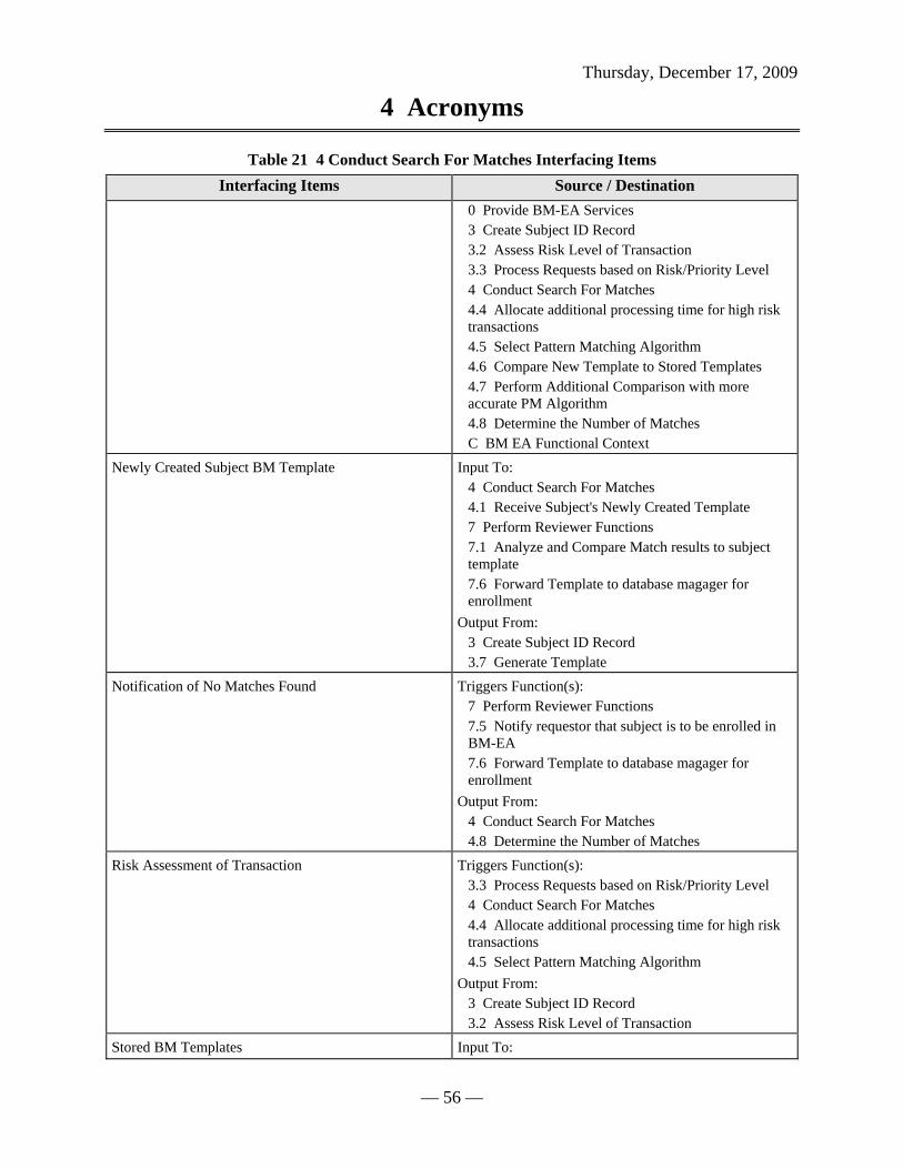
Thursday, December 17, 2009
4 Acronyms
— 56 —
Table 21 4 Conduct Search For Matches Interfacing Items Interfacing Items Source / Destination
0 Provide BM-EA Services 3 Create Subject ID Record 3.2 Assess Risk Level of Transaction 3.3 Process Requests based on Risk/Priority Level 4 Conduct Search For Matches 4.4 Allocate additional processing time for high risk transactions 4.5 Select Pattern Matching Algorithm 4.6 Compare New Template to Stored Templates 4.7 Perform Additional Comparison with more accurate PM Algorithm 4.8 Determine the Number of Matches C BM EA Functional Context
Newly Created Subject BM Template Input To: 4 Conduct Search For Matches 4.1 Receive Subject's Newly Created Template 7 Perform Reviewer Functions 7.1 Analyze and Compare Match results to subject template 7.6 Forward Template to database magager for enrollment
Output From: 3 Create Subject ID Record 3.7 Generate Template
Notification of No Matches Found Triggers Function(s): 7 Perform Reviewer Functions 7.5 Notify requestor that subject is to be enrolled in BM-EA 7.6 Forward Template to database magager for enrollment
Output From: 4 Conduct Search For Matches 4.8 Determine the Number of Matches
Risk Assessment of Transaction Triggers Function(s): 3.3 Process Requests based on Risk/Priority Level 4 Conduct Search For Matches 4.4 Allocate additional processing time for high risk transactions 4.5 Select Pattern Matching Algorithm
Output From: 3 Create Subject ID Record 3.2 Assess Risk Level of Transaction
Stored BM Templates Input To:

Thursday, December 17, 2009
4 Acronyms
— 57 —
Table 21 4 Conduct Search For Matches Interfacing Items Interfacing Items Source / Destination
4 Conduct Search For Matches 4.3 Access Stored BM Templates from Database for Comparison
Output From: 5 Store Data 5.6 Store BM Templates/Subject ID Record
Top match results Input To: 4.7 Perform Additional Comparison with more accurate PM Algorithm
Triggers Function(s): 7 Perform Reviewer Functions 7.1 Analyze and Compare Match results to subject template
Output From: 4 Conduct Search For Matches 4.8 Determine the Number of Matches
3
Create SubjectID Record
4.1
Receive Subject'sNewly Created
Template
4.2Determine
Transaction Type(Fingerprint,
Facial, Iris, etc.)
4.3Access Stored BMTemplates fromDatabase forComparison
4.4Allocate
additionalprocessing time
for high risk tra...
4.5
Select PatternMatchingAlgorithm
4.6
Compare NewTemplate to
Stored Templates
4.7Perform
AdditionalComparison withmore accurate ...
4.8
Determine theNumber ofMatches
7
PerformReviewerFunctions
NewlyCreated ...
Subject'sTemplate
TransactionType
Stored BMTemplates
Templatesfrom Dat...
AdditionalProcessin...
RiskAssessme...
CurrentThreat Le...
AlgorithmSelection
ComparisonData
Top matchresults
AdditionalComparis...
Notificationof No Mat...
Date:Thursday, December 17, 2009
Author:University User
Number:4
Name:(University) Conduct Search For Matches
Figure 21 Conduct Search For Matches Enhanced FFBD
3
Create SubjectID Record
4.1
Receive Subject'sNewly Created
Template
4.2Determine
Transaction Type(Fingerprint,
Facial, Iris, etc.)
4.3Access Stored BMTemplates fromDatabase forComparison
4.4Allocate
additionalprocessing time
for high risk tra...
4.5
Select PatternMatchingAlgorithm
4.6
Compare NewTemplate to
Stored Templates
4.7Perform
AdditionalComparison withmore accurate ...
4.8
Determine theNumber ofMatches
7
PerformReviewerFunctions
Date:Thursday, December 17, 2009
Author:University User
Number:4
Name:(University) Conduct Search For Matches
Figure 22 Conduct Search For Matches FFBD

Thursday, December 17, 2009
4 Acronyms
— 58 —
Notificationof No
Matches Fo...Top match r...
NewlyCreated
Subject BMTemplate
4.1
Receive Subject'sNewly Created
Template
Subject'sTemplate
4.2
DetermineTransaction Type
(Fingerprint,Facial, Iris, etc.)
Stored BMTemplates
TransactionType
4.3
Access Stored BMTemplates fromDatabase forComparison
CurrentThreat Levels
RiskAssessment...
4.4Allocate
additionalprocessing time
for high risktransactions
CurrentThreat Levels
RiskAssessment...
TransactionType
4.5
Select PatternMatchingAlgorithm
CurrentThreat Levels
Subject'sTemplate
Templatesfrom
Database
AdditionalProcessing
Power
AlgorithmSelection
4.6
Compare NewTemplate to
Stored Templates
CurrentThreat Levels
Top matchresults
Subject'sTemplate
AlgorithmSelection
4.7Perform
AdditionalComparison withmore accuratePM Algorithm
Top matchresults
CurrentThreat Levels
ComparisonData
AdditionalComparison
Data
4.8
Determine theNumber ofMatches
Date:Thursday, December 17, 2009
Author:University User
Number:4
Name:(University) Conduct Search For Matches
Figure 23 Conduct Search For Matches N2 Diagram

Thursday, December 17, 2009
4 Acronyms
— 59 —
Transaction Type
Current Threat Levels
Comparison Data
Algorithm Selection
Additional Processing Power
Additional Comparison Data
Matching Component
Top match results
Subject's TemplateSubject's Template
Transaction Type
Top matchresults
Templates from Database
Subject's Template
Stored BM Templates
Risk Assessment of Transaction
Notification of No Matches Found
Newly Created Subject BM Template
Algorithm Selection
4.1
Receive Subject'sNewly Created
Template
4.2Determine
Transaction Type(Fingerprint,
Facial, Iris, etc.)
4.3Access Stored BMTemplates fromDatabase forComparison
4.4Allocate
additionalprocessing time
for high risk tra...
4.5
Select PatternMatchingAlgorithm
4.6
Compare NewTemplate to
Stored Templates
4.7Perform
AdditionalComparison withmore accurate ...
4.8
Determine theNumber ofMatches
Date:Thursday, December 17, 2009
Author:University User
Number:4
Name:(University) Conduct Search For Matches
Figure 24 Conduct Search For Matches IDEF0 Diagram
4.1 Receive Subject's Newly Created Template Description:
The newly created subject template will be received by the pattern matcher.
Allocated To: SYS.1.4 Matching Component
Table 22 4.1 Receive Subject's Newly Created Template Interfacing Items Interfacing Items Source / Destination
Newly Created Subject BM Template Input To: 4 Conduct Search For Matches 4.1 Receive Subject's Newly Created Template 7 Perform Reviewer Functions 7.1 Analyze and Compare Match results to subject template 7.6 Forward Template to database magager for enrollment

Thursday, December 17, 2009
4 Acronyms
— 60 —
Table 22 4.1 Receive Subject's Newly Created Template Interfacing Items Interfacing Items Source / Destination
Output From: 3 Create Subject ID Record 3.7 Generate Template
Subject's Template Triggers Function(s): 4.2 Determine Transaction Type (Fingerprint, Facial, Iris, etc.) 4.6 Compare New Template to Stored Templates 4.7 Perform Additional Comparison with more accurate PM Algorithm
Output From: 4.1 Receive Subject's Newly Created Template
4.2 Determine Transaction Type (Fingerprint, Facial, Iris, etc.) Description:
The transaction type will be determined based on the characteristics of the raw image and processed accordingly.
Allocated To: SYS.1.4 Matching Component
Table 23 4.2 Determine Transaction Type (Fingerprint, Facial, Iris, etc.) Interfacing Items Interfacing Items Source / Destination
Subject's Template Triggers Function(s): 4.2 Determine Transaction Type (Fingerprint, Facial, Iris, etc.) 4.6 Compare New Template to Stored Templates 4.7 Perform Additional Comparison with more accurate PM Algorithm
Output From: 4.1 Receive Subject's Newly Created Template
Transaction Type Input To: 4.5 Select Pattern Matching Algorithm
Triggers Function(s): 4.3 Access Stored BM Templates from Database for Comparison
Output From: 4.2 Determine Transaction Type (Fingerprint, Facial, Iris, etc.)

Thursday, December 17, 2009
4 Acronyms
— 61 —
4.3 Access Stored BM Templates from Database for Comparison Description:
Stored biometric templates will be pulled from the database for comparison.
Allocated To: SYS.1.4 Matching Component
Table 24 4.3 Access Stored BM Templates from Database for Comparison Interfacing Items Interfacing Items Source / Destination
Stored BM Templates Input To: 4 Conduct Search For Matches 4.3 Access Stored BM Templates from Database for Comparison
Output From: 5 Store Data 5.6 Store BM Templates/Subject ID Record
Templates from Database Triggers Function(s): 4.6 Compare New Template to Stored Templates
Output From: 4.3 Access Stored BM Templates from Database for Comparison
Transaction Type Input To: 4.5 Select Pattern Matching Algorithm
Triggers Function(s): 4.3 Access Stored BM Templates from Database for Comparison
Output From: 4.2 Determine Transaction Type (Fingerprint, Facial, Iris, etc.)
4.4 Allocate additional processing time for high risk transactions Description:
Those transactions that were determined to be high risk are allocated additional processing time.
Allocated To: SYS.1.4 Matching Component
Table 25 4.4 Allocate additional processing time for high risk transactions Interfacing Items Interfacing Items Source / Destination
Additional Processing Power Input To: 4.6 Compare New Template to Stored Templates
Output From: 4.4 Allocate additional processing time for high risk

Thursday, December 17, 2009
4 Acronyms
— 62 —
Table 25 4.4 Allocate additional processing time for high risk transactions Interfacing Items Interfacing Items Source / Destination
transactions Current Threat Levels Triggers Function(s):
0 Provide BM-EA Services 3 Create Subject ID Record 3.2 Assess Risk Level of Transaction 3.3 Process Requests based on Risk/Priority Level 4 Conduct Search For Matches 4.4 Allocate additional processing time for high risk transactions 4.5 Select Pattern Matching Algorithm 4.6 Compare New Template to Stored Templates 4.7 Perform Additional Comparison with more accurate PM Algorithm 4.8 Determine the Number of Matches C BM EA Functional Context
Risk Assessment of Transaction Triggers Function(s): 3.3 Process Requests based on Risk/Priority Level 4 Conduct Search For Matches 4.4 Allocate additional processing time for high risk transactions 4.5 Select Pattern Matching Algorithm
Output From: 3 Create Subject ID Record 3.2 Assess Risk Level of Transaction
4.5 Select Pattern Matching Algorithm Description:
The searcher will have the option to select a best fit pattern matching algorithm based on factors such as the level of accuracy required for this particular transaction, or how fast a response is needed.
Allocated To: SYS.1.4 Matching Component
Table 26 4.5 Select Pattern Matching Algorithm Interfacing Items Interfacing Items Source / Destination
Algorithm Selection Input To: 4.6 Compare New Template to Stored Templates 4.7 Perform Additional Comparison with more accurate PM Algorithm
Output From:
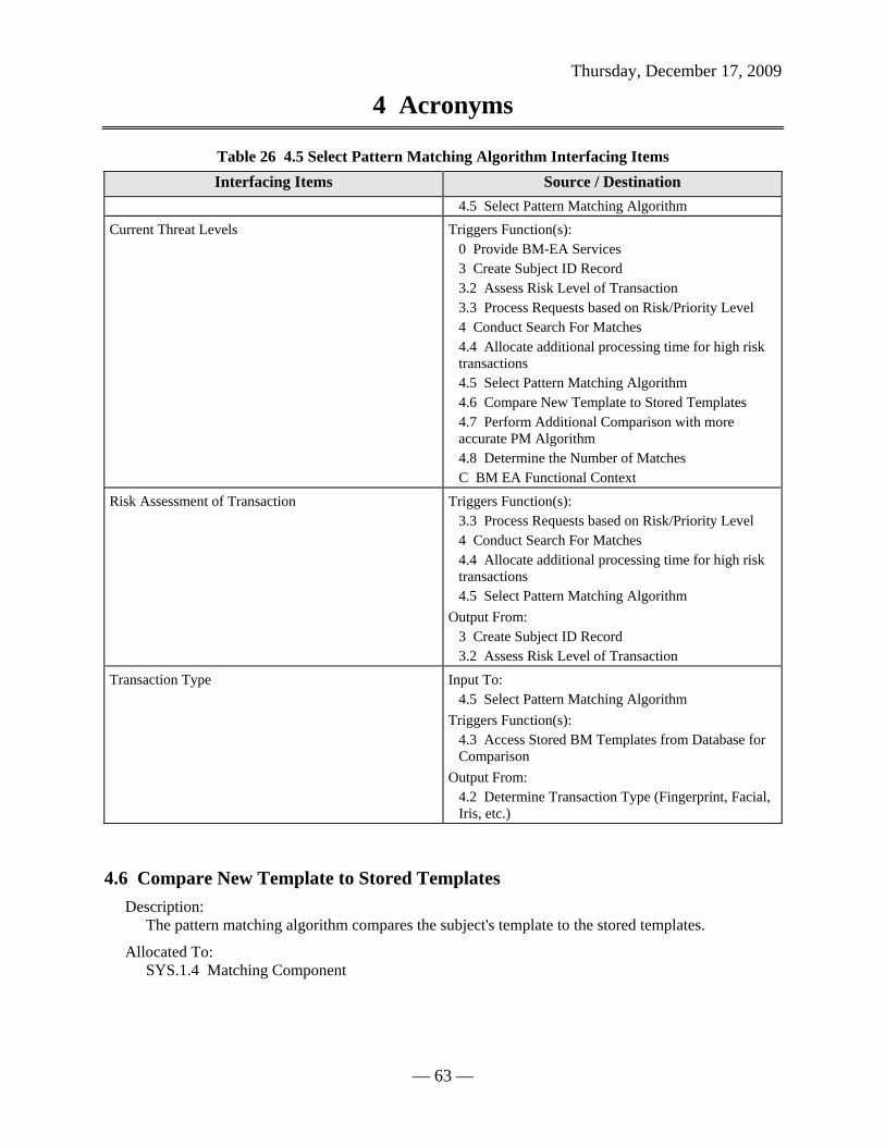
Thursday, December 17, 2009
4 Acronyms
— 63 —
Table 26 4.5 Select Pattern Matching Algorithm Interfacing Items Interfacing Items Source / Destination
4.5 Select Pattern Matching Algorithm Current Threat Levels Triggers Function(s):
0 Provide BM-EA Services 3 Create Subject ID Record 3.2 Assess Risk Level of Transaction 3.3 Process Requests based on Risk/Priority Level 4 Conduct Search For Matches 4.4 Allocate additional processing time for high risk transactions 4.5 Select Pattern Matching Algorithm 4.6 Compare New Template to Stored Templates 4.7 Perform Additional Comparison with more accurate PM Algorithm 4.8 Determine the Number of Matches C BM EA Functional Context
Risk Assessment of Transaction Triggers Function(s): 3.3 Process Requests based on Risk/Priority Level 4 Conduct Search For Matches 4.4 Allocate additional processing time for high risk transactions 4.5 Select Pattern Matching Algorithm
Output From: 3 Create Subject ID Record 3.2 Assess Risk Level of Transaction
Transaction Type Input To: 4.5 Select Pattern Matching Algorithm
Triggers Function(s): 4.3 Access Stored BM Templates from Database for Comparison
Output From: 4.2 Determine Transaction Type (Fingerprint, Facial, Iris, etc.)
4.6 Compare New Template to Stored Templates Description:
The pattern matching algorithm compares the subject's template to the stored templates.
Allocated To: SYS.1.4 Matching Component
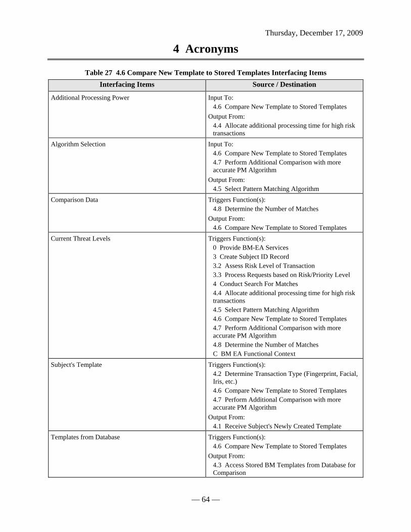
Thursday, December 17, 2009
4 Acronyms
— 64 —
Table 27 4.6 Compare New Template to Stored Templates Interfacing Items Interfacing Items Source / Destination
Additional Processing Power Input To: 4.6 Compare New Template to Stored Templates
Output From: 4.4 Allocate additional processing time for high risk transactions
Algorithm Selection Input To: 4.6 Compare New Template to Stored Templates 4.7 Perform Additional Comparison with more accurate PM Algorithm
Output From: 4.5 Select Pattern Matching Algorithm
Comparison Data Triggers Function(s): 4.8 Determine the Number of Matches
Output From: 4.6 Compare New Template to Stored Templates
Current Threat Levels Triggers Function(s): 0 Provide BM-EA Services 3 Create Subject ID Record 3.2 Assess Risk Level of Transaction 3.3 Process Requests based on Risk/Priority Level 4 Conduct Search For Matches 4.4 Allocate additional processing time for high risk transactions 4.5 Select Pattern Matching Algorithm 4.6 Compare New Template to Stored Templates 4.7 Perform Additional Comparison with more accurate PM Algorithm 4.8 Determine the Number of Matches C BM EA Functional Context
Subject's Template Triggers Function(s): 4.2 Determine Transaction Type (Fingerprint, Facial, Iris, etc.) 4.6 Compare New Template to Stored Templates 4.7 Perform Additional Comparison with more accurate PM Algorithm
Output From: 4.1 Receive Subject's Newly Created Template
Templates from Database Triggers Function(s): 4.6 Compare New Template to Stored Templates
Output From: 4.3 Access Stored BM Templates from Database for Comparison
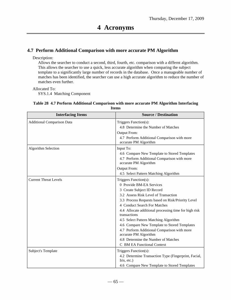
Thursday, December 17, 2009
4 Acronyms
— 65 —
4.7 Perform Additional Comparison with more accurate PM Algorithm Description:
Allows the searcher to conduct a second, third, fourth, etc. comparison with a differnt algorithm. This allows the searcher to use a quick, less accurate algorithm when comparing the subject template to a significantly large number of records in the database. Once a manageable number of matches has been identified, the searcher can use a high accurate algorithm to reduce the number of matches even further.
Allocated To: SYS.1.4 Matching Component
Table 28 4.7 Perform Additional Comparison with more accurate PM Algorithm Interfacing Items
Interfacing Items Source / Destination
Additional Comparison Data Triggers Function(s): 4.8 Determine the Number of Matches
Output From: 4.7 Perform Additional Comparison with more accurate PM Algorithm
Algorithm Selection Input To: 4.6 Compare New Template to Stored Templates 4.7 Perform Additional Comparison with more accurate PM Algorithm
Output From: 4.5 Select Pattern Matching Algorithm
Current Threat Levels Triggers Function(s): 0 Provide BM-EA Services 3 Create Subject ID Record 3.2 Assess Risk Level of Transaction 3.3 Process Requests based on Risk/Priority Level 4 Conduct Search For Matches 4.4 Allocate additional processing time for high risk transactions 4.5 Select Pattern Matching Algorithm 4.6 Compare New Template to Stored Templates 4.7 Perform Additional Comparison with more accurate PM Algorithm 4.8 Determine the Number of Matches C BM EA Functional Context
Subject's Template Triggers Function(s): 4.2 Determine Transaction Type (Fingerprint, Facial, Iris, etc.) 4.6 Compare New Template to Stored Templates

Thursday, December 17, 2009
4 Acronyms
— 66 —
Table 28 4.7 Perform Additional Comparison with more accurate PM Algorithm Interfacing Items
Interfacing Items Source / Destination 4.7 Perform Additional Comparison with more accurate PM Algorithm
Output From: 4.1 Receive Subject's Newly Created Template
Top match results Input To: 4.7 Perform Additional Comparison with more accurate PM Algorithm
Triggers Function(s): 7 Perform Reviewer Functions 7.1 Analyze and Compare Match results to subject template
Output From: 4 Conduct Search For Matches 4.8 Determine the Number of Matches
4.8 Determine the Number of Matches Description:
The number of matches are determined based on the threshold set for BM-EA at that particular time. If the threshold is set high, the risk for false matches is reduced, however the probability of missing some true matches is increased as well.
Allocated To: SYS.1.4 Matching Component
Table 29 4.8 Determine the Number of Matches Interfacing Items Interfacing Items Source / Destination
Additional Comparison Data Triggers Function(s): 4.8 Determine the Number of Matches
Output From: 4.7 Perform Additional Comparison with more accurate PM Algorithm
Comparison Data Triggers Function(s): 4.8 Determine the Number of Matches
Output From: 4.6 Compare New Template to Stored Templates
Current Threat Levels Triggers Function(s): 0 Provide BM-EA Services 3 Create Subject ID Record 3.2 Assess Risk Level of Transaction 3.3 Process Requests based on Risk/Priority Level

Thursday, December 17, 2009
4 Acronyms
— 67 —
Table 29 4.8 Determine the Number of Matches Interfacing Items Interfacing Items Source / Destination
4 Conduct Search For Matches 4.4 Allocate additional processing time for high risk transactions 4.5 Select Pattern Matching Algorithm 4.6 Compare New Template to Stored Templates 4.7 Perform Additional Comparison with more accurate PM Algorithm 4.8 Determine the Number of Matches C BM EA Functional Context
Notification of No Matches Found Triggers Function(s): 7 Perform Reviewer Functions 7.5 Notify requestor that subject is to be enrolled in BM-EA 7.6 Forward Template to database magager for enrollment
Output From: 4 Conduct Search For Matches 4.8 Determine the Number of Matches
Top match results Input To: 4.7 Perform Additional Comparison with more accurate PM Algorithm
Triggers Function(s): 7 Perform Reviewer Functions 7.1 Analyze and Compare Match results to subject template
Output From: 4 Conduct Search For Matches 4.8 Determine the Number of Matches
5 Store Data Description:
BM-EA will store all biometric data related to the subjects.
Allocated To: SYS.1.5 Data Storage Component
Table 30 5 Store Data Interfacing Items Interfacing Items Source / Destination
Capacity and performance requirements Input To: 5 Store Data 5.7 Scale/Partition as necessary to satisfy speed

Thursday, December 17, 2009
4 Acronyms
— 68 —
Table 30 5 Store Data Interfacing Items Interfacing Items Source / Destination
requirements C.4 Provide Network Support
Output From: 0 Provide BM-EA Services 6 Conduct Performance Tests 6.3 Relay capacity/performance requirements to the network infrastructure
New Template to Enroll Triggers Function(s): 5 Store Data 5.2 Associate raw image data with corresponding template 5.3 Input additional biographic info to complete template
Output From: 7 Perform Reviewer Functions 7.6 Forward Template to database magager for enrollment
Raw Image Data Input To: 3 Create Subject ID Record 3.4 Enhance Raw Image 5 Store Data 5.1 Store Raw Image Data 5.2 Associate raw image data with corresponding template
Triggers Function(s): 2.2 Execute Quality Assessement
Output From: 2 Assess Image Quality 2.1 Accept Request for Image Quality Assessment
Stored BM Templates Input To: 4 Conduct Search For Matches 4.3 Access Stored BM Templates from Database for Comparison
Output From: 5 Store Data 5.6 Store BM Templates/Subject ID Record

Thursday, December 17, 2009
4 Acronyms
— 69 —
1
Accept Requestsand ProvideFeedback
5.1
Store Raw ImageData
5.2Associate raw
image data withcorresponding
template
5.3
Input additionalbiographic info tocomplete template
5.4Search Database
for other BMmodality info
related to Subject
5.5
Fuse fingerprint,iris, facial, voice
data for all entries
5.6
Store BMTemplates/
Subject ID Record
5.7Scale/Partition as
necessary tosatisfy speedrequirements
7
PerformReviewerFunctions
Raw ImageData
NewTemplate ...
CompletedTemplate
AdditionalSubject I...
Templatewith Fuse...
Stored BMTemplates
Capacityand perf...
Date:Thursday, December 17, 2009
Author:University User
Number:5
Name:(University) Store Data
Figure 25 Store Data Enhanced FFBD
1
Accept Requestsand ProvideFeedback
5.1
Store Raw ImageData
5.2Associate raw
image data withcorresponding
template
5.3
Input additionalbiographic info tocomplete template
5.4Search Database
for other BMmodality info
related to Subject
5.5
Fuse fingerprint,iris, facial, voice
data for all entries
5.6
Store BMTemplates/
Subject ID Record
5.7Scale/Partition as
necessary tosatisfy speedrequirements
7
PerformReviewerFunctions
Date:Thursday, December 17, 2009
Author:University User
Number:5
Name:(University) Store Data
Figure 26 Store Data FFBD

Thursday, December 17, 2009
4 Acronyms
— 70 —
Stored BMTemplates
Raw ImageData
5.1
Store Raw ImageData
NewTemplate to
EnrollRaw Image...
5.2
Associate rawimage data withcorresponding
template
NewTemplate to
Enroll
5.3
Input additionalbiographic info tocomplete template
CompletedTemplate
5.4
Search Databasefor other BMmodality info
related to Subject
CompletedTemplate
AdditionalSubject Info
5.5
Fuse fingerprint,iris, facial, voice
data for all entries
Templatewith Fused
Data
5.6
Store BMTemplates/
Subject ID Record
Capacity andperformancerequirements
5.7
Scale/Partition asnecessary tosatisfy speedrequirements
Date:Thursday, December 17, 2009
Author:University User
Number:5
Name:(University) Store Data
Figure 27 Store Data N2 Diagram

Thursday, December 17, 2009
4 Acronyms
— 71 —
Data Storage Component
Database StructureRaw Image Database
Raw Image Data
New Template to Enroll
Completed Template
Capacity and performance requirements
Template Database
Additional Subject Info
Template with Fused Data
Stored BM Templates
Data Association Component Data Fusion ComponentDatabase ManagerDatabase Manager
Completed Template
5.1
Store Raw ImageData
5.2Associate raw
image data withcorresponding
template
5.3
Input additionalbiographic info tocomplete template
5.4Search Database
for other BMmodality info
related to Subject
5.5
Fuse fingerprint,iris, facial, voice
data for all entries
5.6
Store BMTemplates/
Subject ID Record
5.7Scale/Partition as
necessary tosatisfy speedrequirements
Date:Thursday, December 17, 2009
Author:University User
Number:5
Name:(University) Store Data
Figure 28 Store Data IDEF0 Diagram
5.1 Store Raw Image Data Description:
Raw image data submitted by subjects will be stored.
Allocated To: SYS.1.5.1 Raw Image Database
Table 31 5.1 Store Raw Image Data Interfacing Items Interfacing Items Source / Destination
Raw Image Data Input To: 3 Create Subject ID Record 3.4 Enhance Raw Image 5 Store Data 5.1 Store Raw Image Data 5.2 Associate raw image data with corresponding template
Triggers Function(s): 2.2 Execute Quality Assessement

Thursday, December 17, 2009
4 Acronyms
— 72 —
Table 31 5.1 Store Raw Image Data Interfacing Items Interfacing Items Source / Destination
Output From: 2 Assess Image Quality 2.1 Accept Request for Image Quality Assessment
5.2 Associate raw image data with corresponding template Description:
Once templates are generated, the raw image data will be associated to its corresponding template.
Allocated To: SYS.1.5.2 Data Association Component Table 32 5.2 Associate raw image data with corresponding template Interfacing Items
Interfacing Items Source / Destination
New Template to Enroll Triggers Function(s): 5 Store Data 5.2 Associate raw image data with corresponding template 5.3 Input additional biographic info to complete template
Output From: 7 Perform Reviewer Functions 7.6 Forward Template to database magager for enrollment
Raw Image Data Input To: 3 Create Subject ID Record 3.4 Enhance Raw Image 5 Store Data 5.1 Store Raw Image Data 5.2 Associate raw image data with corresponding template
Triggers Function(s): 2.2 Execute Quality Assessement
Output From: 2 Assess Image Quality 2.1 Accept Request for Image Quality Assessment
5.3 Input additional biographic info to complete template Description:
A database manager will input any missing biographic info to ensure that the template represesnts a complete subject ID record.

Thursday, December 17, 2009
4 Acronyms
— 73 —
Allocated To: SYS.1.5.3 Database Manager
Table 33 5.3 Input additional biographic info to complete template Interfacing Items Interfacing Items Source / Destination
Completed Template Triggers Function(s): 5.4 Search Database for other BM modality info related to Subject 5.5 Fuse fingerprint, iris, facial, voice data for all entries
Output From: 5.3 Input additional biographic info to complete template
New Template to Enroll Triggers Function(s): 5 Store Data 5.2 Associate raw image data with corresponding template 5.3 Input additional biographic info to complete template
Output From: 7 Perform Reviewer Functions 7.6 Forward Template to database magager for enrollment
5.4 Search Database for other BM modality info related to Subject Description:
The database manager will search BM-EA to find other records related to the subject under different biometric modalities. For example, a facial biometric template for the subject may have just been created, however the subject may have a fingerprint template already stored in the database, in which case we will want to fuse these records.
Allocated To: SYS.1.5.3 Database Manager
Table 34 5.4 Search Database for other BM modality info related to Subject Interfacing Items Interfacing Items Source / Destination
Additional Subject Info Triggers Function(s): 5.5 Fuse fingerprint, iris, facial, voice data for all entries
Output From: 5.4 Search Database for other BM modality info related to Subject
Completed Template Triggers Function(s): 5.4 Search Database for other BM modality info
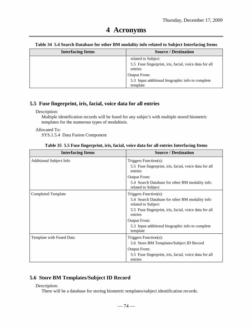
Thursday, December 17, 2009
4 Acronyms
— 74 —
Table 34 5.4 Search Database for other BM modality info related to Subject Interfacing Items Interfacing Items Source / Destination
related to Subject 5.5 Fuse fingerprint, iris, facial, voice data for all entries
Output From: 5.3 Input additional biographic info to complete template
5.5 Fuse fingerprint, iris, facial, voice data for all entries Description:
Multiple identification records will be fused for any subjec's with multiple stored biometric templates for the numerous types of modaltieis.
Allocated To: SYS.1.5.4 Data Fusion Component
Table 35 5.5 Fuse fingerprint, iris, facial, voice data for all entries Interfacing Items Interfacing Items Source / Destination
Additional Subject Info Triggers Function(s): 5.5 Fuse fingerprint, iris, facial, voice data for all entries
Output From: 5.4 Search Database for other BM modality info related to Subject
Completed Template Triggers Function(s): 5.4 Search Database for other BM modality info related to Subject 5.5 Fuse fingerprint, iris, facial, voice data for all entries
Output From: 5.3 Input additional biographic info to complete template
Template with Fused Data Triggers Function(s): 5.6 Store BM Templates/Subject ID Record
Output From: 5.5 Fuse fingerprint, iris, facial, voice data for all entries
5.6 Store BM Templates/Subject ID Record Description:
There will be a database for storing biometric templates/subject identification records.

Thursday, December 17, 2009
4 Acronyms
— 75 —
Allocated To: SYS.1.5.5 Template Database
Table 36 5.6 Store BM Templates/Subject ID Record Interfacing Items Interfacing Items Source / Destination
Stored BM Templates Input To: 4 Conduct Search For Matches 4.3 Access Stored BM Templates from Database for Comparison
Output From: 5 Store Data 5.6 Store BM Templates/Subject ID Record
Template with Fused Data Triggers Function(s): 5.6 Store BM Templates/Subject ID Record
Output From: 5.5 Fuse fingerprint, iris, facial, voice data for all entries
5.7 Scale/Partition as necessary to satisfy speed requirements Description:
When a search is being conducted, the database will scale/partition as necessary to satsify speed requirements.
Allocated To: SYS.1.5.6 Database Structure
Table 37 5.7 Scale/Partition as necessary to satisfy speed requirements Interfacing Items Interfacing Items Source / Destination
Capacity and performance requirements Input To: 5 Store Data 5.7 Scale/Partition as necessary to satisfy speed requirements C.4 Provide Network Support
Output From: 0 Provide BM-EA Services 6 Conduct Performance Tests 6.3 Relay capacity/performance requirements to the network infrastructure
6 Conduct Performance Tests Description:
The BM-EA will have performance tests conducted by a tester role.

Thursday, December 17, 2009
4 Acronyms
— 76 —
Allocated To: SYS.1.6 Tester Component
Table 38 6 Conduct Performance Tests Interfacing Items Interfacing Items Source / Destination
Capacity and performance requirements Input To: 5 Store Data 5.7 Scale/Partition as necessary to satisfy speed requirements C.4 Provide Network Support
Output From: 0 Provide BM-EA Services 6 Conduct Performance Tests 6.3 Relay capacity/performance requirements to the network infrastructure
Current Network Performance Levels Input To: 0 Provide BM-EA Services 6 Conduct Performance Tests 6.1 Identify niche Algorithms for specific transaction types 6.2 Process hypothetical transactions under different threat levels 6.3 Relay capacity/performance requirements to the network infrastructure
Output From: C.4 Provide Network Support
1
Accept Requestsand ProvideFeedback
6.1Identify nicheAlgorithms for
specifictransaction types
6.2Process
hypotheticaltransactions
under different ...
6.3Relay
capacity/performance
requirements to...
7
PerformReviewerFunctions
CurrentNetwork ...
Capacityand perf...
Date:Thursday, December 17, 2009
Author:University User
Number:6
Name:(University) Conduct Performance Tests
Figure 29 Conduct Performance Tests Enhanced FFBD

Thursday, December 17, 2009
4 Acronyms
— 77 —
1
Accept Requestsand ProvideFeedback
6.1Identify nicheAlgorithms for
specifictransaction types
6.2Process
hypotheticaltransactions
under different ...
6.3Relay
capacity/performance
requirements to...
7
PerformReviewerFunctions
Date:Thursday, December 17, 2009
Author:University User
Number:6
Name:(University) Conduct Performance Tests
Figure 30 Conduct Performance Tests FFBD
Capacity andperformancerequirements
CurrentNetwork
PerformanceLevels
6.1
Identify nicheAlgorithms for
specifictransaction types
CurrentNetwork
PerformanceLevels
6.2Process
hypotheticaltransactions
under differentthreat levels
CurrentNetwork
PerformanceLevels
6.3Relay
capacity/performance
requirements tothe network infr...
Date:Thursday, December 17, 2009
Author:University User
Number:6
Name:(University) Conduct Performance Tests
Figure 31 Conduct Performance Tests N2 Diagram

Thursday, December 17, 2009
4 Acronyms
— 78 —
Tester Component
Current Network Performance Levels
Capacity and performance requirements
6.1Identify nicheAlgorithms for
specifictransaction types
6.2Process
hypotheticaltransactions
under different ...
6.3Relay
capacity/performance
requirements to...
Date:Thursday, December 17, 2009
Author:University User
Number:6
Name:(University) Conduct Performance Tests
Figure 32 Conduct Performance Tests IDEF0 Diagram
6.1 Identify niche Algorithms for specific transaction types Description:
The tester will conduct tests to identify niche algorithms for specific transaction types. In other words, the tester is responsbile for determining which algorithms work the best for a particular type of transaction based on factors such as the level of accuracy required, the response time required, and the modality type.
Allocated To: SYS.1.6 Tester Component Table 39 6.1 Identify niche Algorithms for specific transaction types Interfacing Items
Interfacing Items Source / Destination
Current Network Performance Levels Input To: 0 Provide BM-EA Services 6 Conduct Performance Tests 6.1 Identify niche Algorithms for specific transaction types 6.2 Process hypothetical transactions under different threat levels 6.3 Relay capacity/performance requirements to the network infrastructure
Output From:

Thursday, December 17, 2009
4 Acronyms
— 79 —
Table 39 6.1 Identify niche Algorithms for specific transaction types Interfacing Items Interfacing Items Source / Destination
C.4 Provide Network Support
6.2 Process hypothetical transactions under different threat levels Description:
The tester will process hypothetical transactions to determine which algorithms are most effective under various types of threat levels.
Allocated To: SYS.1.6 Tester Component
Table 40 6.2 Process hypothetical transactions under different threat levels Interfacing Items Interfacing Items Source / Destination
Current Network Performance Levels Input To: 0 Provide BM-EA Services 6 Conduct Performance Tests 6.1 Identify niche Algorithms for specific transaction types 6.2 Process hypothetical transactions under different threat levels 6.3 Relay capacity/performance requirements to the network infrastructure
Output From: C.4 Provide Network Support
6.3 Relay capacity/performance requirements to the network infrastructure Description:
The tester will relay BM-EA capacity and performance requirements to the enterprise network supporting BM-EA.
Allocated To: SYS.1.6 Tester Component
Table 41 6.3 Relay capacity/performance requirements to the network infrastructure Interfacing Items
Interfacing Items Source / Destination
Capacity and performance requirements Input To: 5 Store Data 5.7 Scale/Partition as necessary to satisfy speed requirements C.4 Provide Network Support

Thursday, December 17, 2009
4 Acronyms
— 80 —
Table 41 6.3 Relay capacity/performance requirements to the network infrastructure Interfacing Items
Interfacing Items Source / Destination
Output From: 0 Provide BM-EA Services 6 Conduct Performance Tests 6.3 Relay capacity/performance requirements to the network infrastructure
Current Network Performance Levels Input To: 0 Provide BM-EA Services 6 Conduct Performance Tests 6.1 Identify niche Algorithms for specific transaction types 6.2 Process hypothetical transactions under different threat levels 6.3 Relay capacity/performance requirements to the network infrastructure
Output From: C.4 Provide Network Support
7 Perform Reviewer Functions Description:
BM-EA will have a human reviewer role to add fidelity to the matches found by the automated pattern matching engine.
Allocated To: SYS.1.7 Manual Reviewer
Table 42 7 Perform Reviewer Functions Interfacing Items Interfacing Items Source / Destination
Business Logic Triggers Function(s): 0 Provide BM-EA Services 7 Perform Reviewer Functions 7.1 Analyze and Compare Match results to subject template 7.2 Verify Identity of Subject 7.3 Determine if Subject's Identity requires notification to law enforcement 7.4 Notify requestor to allow/disallow border crossing7.5 Notify requestor that subject is to be enrolled in BM-EA C BM EA Functional Context
Communication to Law Enforcement/Intelligence Agencies/Adjudicators
Output From: 0 Provide BM-EA Services

Thursday, December 17, 2009
4 Acronyms
— 81 —
Table 42 7 Perform Reviewer Functions Interfacing Items Interfacing Items Source / Destination
7 Perform Reviewer Functions 7.3 Determine if Subject's Identity requires notification to law enforcement C BM EA Functional Context
Decision to allow/disallow border crossing Input To: 1 Accept Requests and Provide Feedback 1.5 Notify Requestor to allow/disallow border crossing
Output From: 7 Perform Reviewer Functions 7.4 Notify requestor to allow/disallow border crossing
New Template to Enroll Triggers Function(s): 5 Store Data 5.2 Associate raw image data with corresponding template 5.3 Input additional biographic info to complete template
Output From: 7 Perform Reviewer Functions 7.6 Forward Template to database magager for enrollment
Newly Created Subject BM Template Input To: 4 Conduct Search For Matches 4.1 Receive Subject's Newly Created Template 7 Perform Reviewer Functions 7.1 Analyze and Compare Match results to subject template 7.6 Forward Template to database magager for enrollment
Output From: 3 Create Subject ID Record 3.7 Generate Template
Notification of No Matches Found Triggers Function(s): 7 Perform Reviewer Functions 7.5 Notify requestor that subject is to be enrolled in BM-EA 7.6 Forward Template to database magager for enrollment
Output From: 4 Conduct Search For Matches 4.8 Determine the Number of Matches
Notification that Subject is to be Enrolled Input To: 1 Accept Requests and Provide Feedback

Thursday, December 17, 2009
4 Acronyms
— 82 —
Table 42 7 Perform Reviewer Functions Interfacing Items Interfacing Items Source / Destination
1.6 Notify Requestor that Subject is to be enrolled in BM-EA
Output From: 7 Perform Reviewer Functions 7.5 Notify requestor that subject is to be enrolled in BM-EA
Subject's Identity Input To: 1 Accept Requests and Provide Feedback 1.4 Display Subject's Identity as determined from BM-EA
Triggers Function(s): 7.3 Determine if Subject's Identity requires notification to law enforcement 7.4 Notify requestor to allow/disallow border crossing
Output From: 7 Perform Reviewer Functions 7.2 Verify Identity of Subject
Top match results Input To: 4.7 Perform Additional Comparison with more accurate PM Algorithm
Triggers Function(s): 7 Perform Reviewer Functions 7.1 Analyze and Compare Match results to subject template
Output From: 4 Conduct Search For Matches 4.8 Determine the Number of Matches

Thursday, December 17, 2009
4 Acronyms
— 83 —
2
Assess ImageQuality
4
Conduct SearchFor Matches
5
Store Data
6
ConductPerformance
Tests
AND
7.1Analyze and
Compare Matchresults to subject
template
7.2
Verify Identity ofSubject
7.3Determine if
Subject's Identityrequires
notification to la...
7.4
Notify requestorto allow/disallowborder crossing
7.5Notify requestorthat subject is to
be enrolled inBM-EA
7.6Forward
Template todatabase
magager for enro...
C.3
Use BM-EAServices
NewlyCreated ...
ComparisonAnalysis
BusinessLogic
Top matchresults
Subject'sIdentity
Communication to Law...
Decision toallow/disal...
Notificationthat Subj...
Notificationof No Mat...
NewTemplate ...
Date:Thursday, December 17, 2009
Author:University User
Number:7
Name:(University) Perform Reviewer Functions
Figure 33 Perform Reviewer Functions Enhanced FFBD
2
Assess ImageQuality
4
Conduct SearchFor Matches
5
Store Data
6
ConductPerformance
Tests
AND
7.1Analyze and
Compare Matchresults to subject
template
7.2
Verify Identity ofSubject
7.3Determine if
Subject's Identityrequires
notification to la...
7.4
Notify requestorto allow/disallowborder crossing
7.5Notify requestorthat subject is to
be enrolled inBM-EA
7.6Forward
Template todatabase
magager for enro...
C.3
Use BM-EAServices
Date:Thursday, December 17, 2009
Author:University User
Number:7
Name:(University) Perform Reviewer Functions
Figure 34 Perform Reviewer Functions FFBD
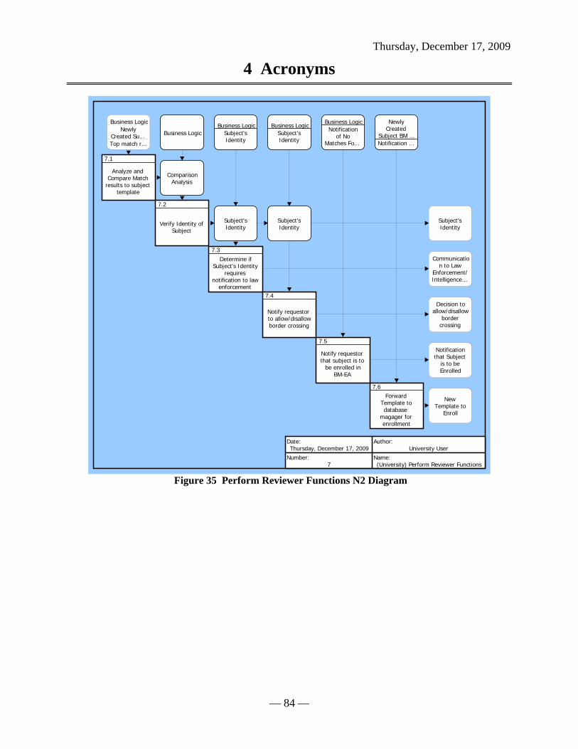
Thursday, December 17, 2009
4 Acronyms
— 84 —
Subject'sIdentity
Communication to Law
Enforcement/Intelligence...
Decision toallow/disallow
bordercrossing
Notificationthat Subject
is to beEnrolled
NewTemplate to
Enroll
Business LogicNewly
Created Su...Top match r...
7.1
Analyze andCompare Match
results to subjecttemplate
Business Logic
ComparisonAnalysis
7.2
Verify Identity ofSubject
Business LogicSubject'sIdentity
Subject'sIdentity
7.3Determine if
Subject's Identityrequires
notification to lawenforcement
Business LogicSubject'sIdentity
Subject'sIdentity
7.4
Notify requestorto allow/disallowborder crossing
Business LogicNotification
of NoMatches Fo...
7.5
Notify requestorthat subject is to
be enrolled inBM-EA
NewlyCreated
Subject BM ...Notification ...
7.6Forward
Template todatabase
magager forenrollment
Date:Thursday, December 17, 2009
Author:University User
Number:7
Name:(University) Perform Reviewer Functions
Figure 35 Perform Reviewer Functions N2 Diagram

Thursday, December 17, 2009
4 Acronyms
— 85 —
Notification that Subject is to be Enrolled
Subject's IdentitySubject's Identity
Top match results
Subject's Identity
Notification of No Matches Found
Newly Created Subject BM Template
New Template to Enroll
Decision to allow/disallow border crossing
Comparison Analysis
Business Logic
Manual Reviewer
Communication to Law Enforcement/Intelligence Agencies/Adjudicators
7.1Analyze and
Compare Matchresults to subject
template
7.2
Verify Identity ofSubject
7.3Determine if
Subject's Identityrequires
notification to la...
7.4
Notify requestorto allow/disallowborder crossing
7.5Notify requestorthat subject is to
be enrolled inBM-EA
7.6Forward
Template todatabase
magager for enro...
Date:Thursday, December 17, 2009
Author:University User
Number:7
Name:(University) Perform Reviewer Functions
Figure 36 Perform Reviewer Functions IDEF0 Diagram
7.1 Analyze and Compare Match results to subject template Description:
Match results will be manually compared to the subject template.
Allocated To: SYS.1.7 Manual Reviewer Table 43 7.1 Analyze and Compare Match results to subject template Interfacing Items
Interfacing Items Source / Destination
Business Logic Triggers Function(s): 0 Provide BM-EA Services 7 Perform Reviewer Functions 7.1 Analyze and Compare Match results to subject template 7.2 Verify Identity of Subject 7.3 Determine if Subject's Identity requires notification to law enforcement 7.4 Notify requestor to allow/disallow border crossing7.5 Notify requestor that subject is to be enrolled in BM-EA

Thursday, December 17, 2009
4 Acronyms
— 86 —
Table 43 7.1 Analyze and Compare Match results to subject template Interfacing Items Interfacing Items Source / Destination
C BM EA Functional Context Comparison Analysis Triggers Function(s):
7.2 Verify Identity of Subject Output From:
7.1 Analyze and Compare Match results to subject template
Newly Created Subject BM Template Input To: 4 Conduct Search For Matches 4.1 Receive Subject's Newly Created Template 7 Perform Reviewer Functions 7.1 Analyze and Compare Match results to subject template 7.6 Forward Template to database magager for enrollment
Output From: 3 Create Subject ID Record 3.7 Generate Template
Top match results Input To: 4.7 Perform Additional Comparison with more accurate PM Algorithm
Triggers Function(s): 7 Perform Reviewer Functions 7.1 Analyze and Compare Match results to subject template
Output From: 4 Conduct Search For Matches 4.8 Determine the Number of Matches
7.2 Verify Identity of Subject Description:
After the manual comparison, the reviewer will verify the identity of the subject.
Allocated To: SYS.1.7 Manual Reviewer
Table 44 7.2 Verify Identity of Subject Interfacing Items Interfacing Items Source / Destination
Business Logic Triggers Function(s): 0 Provide BM-EA Services 7 Perform Reviewer Functions 7.1 Analyze and Compare Match results to subject

Thursday, December 17, 2009
4 Acronyms
— 87 —
Table 44 7.2 Verify Identity of Subject Interfacing Items Interfacing Items Source / Destination
template 7.2 Verify Identity of Subject 7.3 Determine if Subject's Identity requires notification to law enforcement 7.4 Notify requestor to allow/disallow border crossing7.5 Notify requestor that subject is to be enrolled in BM-EA C BM EA Functional Context
Comparison Analysis Triggers Function(s): 7.2 Verify Identity of Subject
Output From: 7.1 Analyze and Compare Match results to subject template
Subject's Identity Input To: 1 Accept Requests and Provide Feedback 1.4 Display Subject's Identity as determined from BM-EA
Triggers Function(s): 7.3 Determine if Subject's Identity requires notification to law enforcement 7.4 Notify requestor to allow/disallow border crossing
Output From: 7 Perform Reviewer Functions 7.2 Verify Identity of Subject
7.3 Determine if Subject's Identity requires notification to law enforcement Description:
Based on the identity determined for the subject and any criminal activities that may be linked to the subject , the reviewer will decide whether or not to notify law enforcement or other adjudicating agencies.
Allocated To: SYS.1.7 Manual Reviewer
Table 45 7.3 Determine if Subject's Identity requires notification to law enforcement Interfacing Items
Interfacing Items Source / Destination
Business Logic Triggers Function(s): 0 Provide BM-EA Services 7 Perform Reviewer Functions 7.1 Analyze and Compare Match results to subject template

Thursday, December 17, 2009
4 Acronyms
— 88 —
Table 45 7.3 Determine if Subject's Identity requires notification to law enforcement Interfacing Items
Interfacing Items Source / Destination 7.2 Verify Identity of Subject 7.3 Determine if Subject's Identity requires notification to law enforcement 7.4 Notify requestor to allow/disallow border crossing7.5 Notify requestor that subject is to be enrolled in BM-EA C BM EA Functional Context
Communication to Law Enforcement/Intelligence Agencies/Adjudicators
Output From: 0 Provide BM-EA Services 7 Perform Reviewer Functions 7.3 Determine if Subject's Identity requires notification to law enforcement C BM EA Functional Context
Subject's Identity Input To: 1 Accept Requests and Provide Feedback 1.4 Display Subject's Identity as determined from BM-EA
Triggers Function(s): 7.3 Determine if Subject's Identity requires notification to law enforcement 7.4 Notify requestor to allow/disallow border crossing
Output From: 7 Perform Reviewer Functions 7.2 Verify Identity of Subject
7.4 Notify requestor to allow/disallow border crossing Description:
Based on the subject's identity the reviewer will notify the requestor to allow or disallow the border crossing.
Allocated To: SYS.1.7 Manual Reviewer
Table 46 7.4 Notify requestor to allow/disallow border crossing Interfacing Items Interfacing Items Source / Destination
Business Logic Triggers Function(s): 0 Provide BM-EA Services 7 Perform Reviewer Functions 7.1 Analyze and Compare Match results to subject template

Thursday, December 17, 2009
4 Acronyms
— 89 —
Table 46 7.4 Notify requestor to allow/disallow border crossing Interfacing Items Interfacing Items Source / Destination
7.2 Verify Identity of Subject 7.3 Determine if Subject's Identity requires notification to law enforcement 7.4 Notify requestor to allow/disallow border crossing7.5 Notify requestor that subject is to be enrolled in BM-EA C BM EA Functional Context
Decision to allow/disallow border crossing Input To: 1 Accept Requests and Provide Feedback 1.5 Notify Requestor to allow/disallow border crossing
Output From: 7 Perform Reviewer Functions 7.4 Notify requestor to allow/disallow border crossing
Subject's Identity Input To: 1 Accept Requests and Provide Feedback 1.4 Display Subject's Identity as determined from BM-EA
Triggers Function(s): 7.3 Determine if Subject's Identity requires notification to law enforcement 7.4 Notify requestor to allow/disallow border crossing
Output From: 7 Perform Reviewer Functions 7.2 Verify Identity of Subject
7.5 Notify requestor that subject is to be enrolled in BM-EA Description:
If there are no matches, and the reviewer confirms that the subject's information does not currently reside in BM-EA, then a notification will be sent to the requestor that the subject is to be enrolled.
Allocated To: SYS.1.7 Manual Reviewer Table 47 7.5 Notify requestor that subject is to be enrolled in BM-EA Interfacing Items
Interfacing Items Source / Destination
Business Logic Triggers Function(s): 0 Provide BM-EA Services 7 Perform Reviewer Functions 7.1 Analyze and Compare Match results to subject template

Thursday, December 17, 2009
4 Acronyms
— 90 —
Table 47 7.5 Notify requestor that subject is to be enrolled in BM-EA Interfacing Items Interfacing Items Source / Destination
7.2 Verify Identity of Subject 7.3 Determine if Subject's Identity requires notification to law enforcement 7.4 Notify requestor to allow/disallow border crossing7.5 Notify requestor that subject is to be enrolled in BM-EA C BM EA Functional Context
Notification of No Matches Found Triggers Function(s): 7 Perform Reviewer Functions 7.5 Notify requestor that subject is to be enrolled in BM-EA 7.6 Forward Template to database magager for enrollment
Output From: 4 Conduct Search For Matches 4.8 Determine the Number of Matches
Notification that Subject is to be Enrolled Input To: 1 Accept Requests and Provide Feedback 1.6 Notify Requestor that Subject is to be enrolled in BM-EA
Output From: 7 Perform Reviewer Functions 7.5 Notify requestor that subject is to be enrolled in BM-EA
7.6 Forward Template to database magager for enrollment Description:
The template is forwarded to the database manager for proper enrollment into the BM-EA system.
Allocated To: SYS.1.7 Manual Reviewer Table 48 7.6 Forward Template to database magager for enrollment Interfacing Items
Interfacing Items Source / Destination
New Template to Enroll Triggers Function(s): 5 Store Data 5.2 Associate raw image data with corresponding template 5.3 Input additional biographic info to complete template
Output From: 7 Perform Reviewer Functions

Thursday, December 17, 2009
4 Acronyms
— 91 —
Table 48 7.6 Forward Template to database magager for enrollment Interfacing Items Interfacing Items Source / Destination
7.6 Forward Template to database magager for enrollment
Newly Created Subject BM Template Input To: 4 Conduct Search For Matches 4.1 Receive Subject's Newly Created Template 7 Perform Reviewer Functions 7.1 Analyze and Compare Match results to subject template 7.6 Forward Template to database magager for enrollment
Output From: 3 Create Subject ID Record 3.7 Generate Template
Notification of No Matches Found Triggers Function(s): 7 Perform Reviewer Functions 7.5 Notify requestor that subject is to be enrolled in BM-EA 7.6 Forward Template to database magager for enrollment
Output From: 4 Conduct Search For Matches 4.8 Determine the Number of Matches

Appendix G
Appendix G. SYSTEMS ENGINEERING MANAGEMENT PLAN (SEMP)
Biometrics Enterprise Architecture Systems Engineering Management Plan
(BMEA SEMP)
Version 1.0
Prepared by:
Date: November 24, 2009

BMEA SYSTEMS ENGINEERING MANAGEMENT PLAN (SEMP)
Final Version 1.0
November 17, 2009
_____________________________________________________________________________________________ i
Revision History
Date Purpose Revision Level Responsible Person
11/17/2009 First Draft 1.0

BMEA SYSTEMS ENGINEERING MANAGEMENT PLAN (SEMP)
Final Version 1.0
November 17, 2009
________________________________________________________________________________________________ ii
Table of Contents
1 Introduction ............................................................................................................................... 5
1.1 Background ...................................................................................................................... 5
1.2 Purpose and Scope ........................................................................................................... 5
1.3 Acronyms ......................................................................................................................... 5
1.1 Applicable Documents ..................................................................................................... 5
2 Systems Engineering Process ................................................................................................... 5
2.1 Organizational Responsibilities and Relationships .......................................................... 5
2.2 Systems Engineering Process Planning ............................................................................ 6
2.2.1 Major Systems Engineering Products 6
2.2.2 Baselines 6
2.2.3 Technical Objectives 7
2.2.4 Work Breakdown Structure 7
2.2.5 Work Authorization 8
2.2.6 Participants 8
2.3 Requirements Analysis ..................................................................................................... 9
2.3.1 Flowdown 9
2.3.2 Engineering Considerations 10
2.3.3 Allocated Requirements 10
2.3.4 Review Process 10
2.4 System Analysis ............................................................................................................. 10
2.4.1 Trade Studies (Analysis of Alternatives) 11
2.4.2 Cost Effectiveness Analyses 11
2.5 System Control ............................................................................................................... 11
2.5.1 Risk Management 11
2.5.2 Configuration Management 12
2.5.3 Interface Management 12
2.5.4 Technical Performance Metrics (TPMs) 12
2.5.5 Technical Reviews 13
2.5.6 Requirements Traceability 14

BMEA SYSTEMS ENGINEERING MANAGEMENT PLAN (SEMP)
Final Version 1.0
November 17, 2009
________________________________________________________________________________________________ iii
2.6 Implementation............................................................................................................... 14
2.6.1 Integration of Systems Engineering Effort 14
2.6.2 Problem Resolution 14
2.6.3 Systems Engineering Plans and Specifications 14
2.7 Other Systems Engineering Activities ........................................................................... 15
2.7.1 Requirements Management Software 15
2.7.2 Database Software 15

BMEA SYSTEMS ENGINEERING MANAGEMENT PLAN (SEMP)
Final Version 1.0
November 17, 2009
________________________________________________________________________________________________ iv
Table of Figures
Figure 1 Organization Chart ........................................................................................................... 6
Figure 2 Breakdown Structure ........................................................................................................ 8
Figure 3 Participating Institutions ................................................................................................... 9
Figure 4 Cost Effectiveness Parameters ....................................................................................... 11
Figure 5 Technical Review Timeline ............................................................................................ 13
Figure 6 Systems Engineering Documentation Plan .................................................................... 15
BMEA SYSTEMS ENGINEERING MANAGEMENT PLAN (SEMP)
Thursday, December 17, 2009
Appendix
________________________________________________________________________________________________ 5
9 INTRODUCTION
The purpose of the BMEA Systems Engineering Management Plan (PMP) is to define the System Engineering methods and associated management methods for BMEA project, and to provide the management approaches and methodologies designed to successfully achieve the project objectives in support of fulfilling the requirements of Systems 798. The overall objective of the BMEA project, in support of modernizing biometrics operational architecture is to develop an executable architecture and a set of technical and business models highlighting the effectiveness of the architecture.
9.1 BACKGROUND Add Background.
9.2 PURPOSE AND SCOPE This Systems Engineering Management Plan (SEMP) describes the activities, processes,
and tools that will by used by the Biometric Enterprise Architecture (BMEA) Systems Engineering team to support the analysis and design of BMEA.
The objective of the Systems Engineering effort is to assure successful development of BMEA primarily by ensuring clear and accurate system requirements and verifying compliance of
to those requirements. The BMEA system consists of the means to connect image requestors, suppliers (subjects), reviewers and adjudicators with the BMEA to introduce, search for, validate, enroll and ratify images and biographical information into BMEA for fusion of various image artifacts into a cohesive collective aggregate identity of an individual. The BMEA is set of image and biographical information storage, search and fusion capabilities for supporting the aggregate identity of individuals supporting identification functions within an enterprise.
This SEMP is applicable to all Systems Engineering tasks to be performed in support of the BMEA project. This document will be placed under change control upon its initial release.
9.3 ACRONYMS SEMP – Systems Engineering Management Plan
SRR – System Requirements Review
WBS – Work Breakdown Structure
APPLICABLE DOCUMENTS The following documents are applicable to the development of this SEMP.
10 SYSTEMS ENGINEERING PROCESS
10.1 ORGANIZATIONAL RESPONSIBILITIES AND RELATIONSHIPS The BMEA team consists of members from the George Mason University’s Systems Engineering/Operational Research Department’s (SEOR) capstone class, SEOR 798/680

BMEA SYSTEMS ENGINEERING MANAGEMENT PLAN (SEMP)
Thursday, December 17, 2009
Appendix
________________________________________________________________________________________________ 6
Systems Engineering and Operations Research Applied Project, within the SEOR Master of Science curriculum and is managed by Dr. Thomas H. Speller, Faculty Professor for SEOR 798/680. BMEA team members report to Dr. Speller who mentors SEOR 798/680 Systems Engineering and Operations Research Applied Project Course on behalf of the SEOR department within the Volgenau School of Information Technology and Engineering at George Mason University. The BMEA manages and is responsible for all systems engineering activities. The organizational structure of the BMEA collaboration is shown in Figure X.
Dr. Speller provides technical leadership and mentors Team BMEA’s BMEA development through tracking project requirements and project performance. Team BMEA is responsible for assuring BMEA meets overall objectives as specified by stakeholders and subject matter experts.
Figure 39 Organization Chart
10.2 SYSTEMS ENGINEERING PROCESS PLANNING This section describes the key components of the BMEA systems engineering process, including the major systems engineering products, technical objectives, work breakdown structure, requirements verification, and engineering participants.
10.2.1 Major Systems Engineering Products
10.2.1.1 Integrated Database Throughout the design phase of the BMEA project, studies and analyses will be conducted to support decisions regarding requirements selection and system design. The collection of these reports and artifacts on the BMEA website effectively documents the process of defining the BMEA and will be archived for future reference. As requirements and specifications are recorded on the BMEA website, they will be cataloged and categorized to the applicable analyses are as described on the website to provide some level of traceability to the rationale for the requirements and for retaining the document on the BMEA website.
10.2.2 Baselines
Throughout the lifecycle of the project, the BMEA system configuration is defined in a technical baseline, consisting of the approved documentation as posted to the BMEA website and is used

BMEA SYSTEMS ENGINEERING MANAGEMENT PLAN (SEMP)
Thursday, December 17, 2009
Appendix
________________________________________________________________________________________________ 7
to record and define the technical requirements of the BMEA project and further define the overall characteristics of the BMEA system including documentation supporting the different development stages of the project. The technical baseline progresses from high-level requirements (the Functional Baseline) to more detailed requirements, design drawings and specifications (the Allocated Baseline) to complete “as-designed” drawings and specifications (the BMEA Baseline). Specifications, interface control documents, and drawing packages are used to describe the BMEA system and are intended for use in further development and implementation activities. These baseline documents will be organized in a hierarchy that provides design traceability to the lowest level. Once approved, these baseline documents are placed under configuration control, as described in the Configuration Management Plan (CMP).
10.2.2.1 Specifications The planned specification tree, Figure 2, shows intended BMEA requirements specification and their intended relationships within BMEA. These requirements are articulated and specified within the BMEA Systems Requirements Specification. The specification tree also represents the flow of requirements from the top-level mission requirements to increasingly detailed requirements for the associated intended and perspective subsystems.
The specifications developed by Team BMEA include:
The specification and sub-levels associated with the high-level requirement for ENROLLING an Image/ID.
The specification and sub-levels associated with the high-level requirement for VALIDATING an Image/ID.
Changes to these specifications require approval of BMEA stakeholder/subject matter experts
10.2.3 Technical Objectives
The technical objectives of the BMEA project are to xxxxx.
The objective of the systems engineering process is to assure that the BMEA capability meets all the requirements that flow down from the mission objectives.
10.2.4 Work Breakdown Structure
The work breakdown structure (WBS) is a hierarchical tree-like depiction of the system development activities as they relate to analysis and design of the BMEA system architecture. The WBS provides a coordinated and complete view of the BMEA Project and is useful for tracking technical systems engineering and non-technical program management activities. The initial WBS has already been developed for this analysis and design phase of the project. The structure of the WBS and its associated network diagram are shown in Figures X and Y. For a detailed description of the WBS elements down to the fourth level, see the BMEA proposal. This WBS is maintained and updated by the Team BMEA and mentored by Dr. Thomas Speller per the syllabus for SEOR 798/690.
The WBS is used by Systems Engineering to aid in: • Identifying products, processes, data and documents. • Organizing risk management analysis and tracking.

BMEA SYSTEMS ENGINEERING MANAGEMENT PLAN (SEMP)
Thursday, December 17, 2009
Appendix
________________________________________________________________________________________________ 8
• Implementing configuration management and control of subsystem interfaces. • Organizing technical reviews and audits.
10.2.5 Work Authorization
The WBS defines the limits of individual responsibility for work efforts. The method for authorizing work within the BMEA Project is defined in the Project Management Plan.
Figure 40 Breakdown Structure
10.2.6 Participants The systems engineering process will involve coordinating the engineering efforts of Team BMEA as analysis and design into the resulting architecture. The engineering participants in the BMEA project are shown in Table X.
Institution Responsibility
Team BMEA
Systems Engineering:
Requirements Elicitation Requirements Refinement System Analysis System Design Project management
Stakeholder Subject Matter Experts
Requirements Articulation Requirements Validation System Assessment
SEOR 798/690
Project Review Project Technical Assessment Proposal Review

BMEA SYSTEMS ENGINEERING MANAGEMENT PLAN (SEMP)
Thursday, December 17, 2009
Appendix
________________________________________________________________________________________________ 9
Institution Responsibility
Dr. T. Speller Project Mentor Systems Engineering Process Review
GMU Faculty Solution Assessment Requirements Coverage
Noblis, Inc.
Requirements Articulation Requirements Validation System Assessment
Figure 41 Participating Institutions
10.3 REQUIREMENTS ANALYSIS Requirements analysis is the iterative process of transforming the mission objectives into a set of requirements that define the characteristics and functions of the system and specify the environment in which it must perform. The process is iterative because as the design of the system progresses, further system analyses result in better understanding of the system and should prompt a reconsideration of the system requirements
10.3.1 Flowdown
The requirements analysis process involves transforming the mission objectives into high level requirements and then further refining those requirements into lower-level requirements and design specifications. The BMEA system requirements flow down from the mission and objectives articulated by both the BMEA stakeholders and subject matter experts. The primary sources of BMEA requirements are:
• ΒΜΕΑ Requirements Document • BMEA Derived Requirements
The high-level BMEA mission requirements are transformed into functional specifications for the BMEA capability set. These specifications are captured in the BMEA functional models, namely, the BMEA Requirements Traceability Diagram. This diagram and associated artifacts undergo extensive review by the Team BMEA and are put under configuration management early in the Formulation Phase, primarily in the Core® modeling tool and posted to the Team BMEA website.
The sub-level performance and design requirements flow down from these requirements specifications and are added to the model as needed. The flow down of requirements is documented and tracked using a requirements management software tool. The BMEA requirements database in Core® provides requirements traceability from the highest to lowest levels.

BMEA SYSTEMS ENGINEERING MANAGEMENT PLAN (SEMP)
Thursday, December 17, 2009
Appendix
________________________________________________________________________________________________ 10
10.3.2 Engineering Considerations
Reliability, maintainability and supportability requirements of the system as well as other human factors are considered when developing and analyzing BMEA requirements. This ensures the BMEA system will meet its requirements over its lifetime and in its operating environment and that it can be logistically supported, operated, and maintained at the intended level of skill and training.
10.3.3 Allocated Requirements
Some system capabilities such as management, and operational systems management capabilities and physical interfaces may be determined to be distributed among the system components in order to meet the overall system requirements. The allocation of these capabilities is assigned based on component distribution amongst the operating capabilities and is determined through BMEA systems and analysis and design and will be allocated to components after functions are determined. The functions, as determined from requirements, are allocated to components through transition from function analysis to component analysis based on those functions. The requirements analysis process and resulting traceability will verify that requirements are correctly allocated to the subsystems.
10.3.4 Review Process
All requirements documents will be subject to review by the appropriate Team BMEA members prior to initial release. The reviewers are responsible for verifying that the higher-level requirements are satisfied. The reviewers should also verify that the requirements have the following attributes:
• Achievable – the requirement must be technically achievable within the allotted schedule and budget constraints.
• Verifiable – the requirement must be expressed in a way that is verifiable by an objective test or analysis.
• Unambiguous – the requirement must have only one possible meaning. • Complete – the set of requirements must contain all the information necessary to
successfully meet the mission objectives, including mission profiles, environments (including enrollment and verification), operational and maintenance concepts and interface constraints.
• Consistent – each requirement must not conflict with another requirement.
10.4 SYSTEM ANALYSIS System analysis is the process of evaluating the system and documenting data and decisions. System analysis activities support all steps of the systems engineering process and provide a quantitative basis for selecting performance, functional, and design requirements. All BMEA system analyses will be documented and archived.
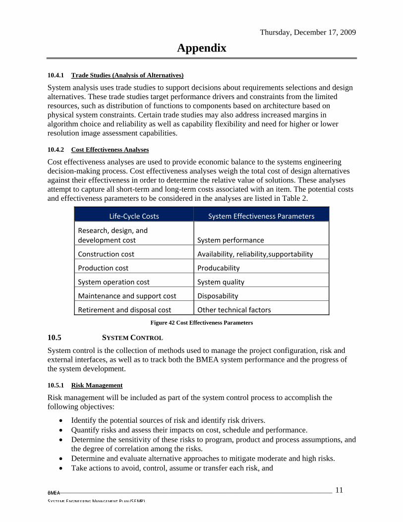
BMEA SYSTEMS ENGINEERING MANAGEMENT PLAN (SEMP)
Thursday, December 17, 2009
Appendix
________________________________________________________________________________________________ 11
10.4.1 Trade Studies (Analysis of Alternatives)
System analysis uses trade studies to support decisions about requirements selections and design alternatives. These trade studies target performance drivers and constraints from the limited resources, such as distribution of functions to components based on architecture based on physical system constraints. Certain trade studies may also address increased margins in algorithm choice and reliability as well as capability flexibility and need for higher or lower resolution image assessment capabilities.
10.4.2 Cost Effectiveness Analyses
Cost effectiveness analyses are used to provide economic balance to the systems engineering decision-making process. Cost effectiveness analyses weigh the total cost of design alternatives against their effectiveness in order to determine the relative value of solutions. These analyses attempt to capture all short-term and long-term costs associated with an item. The potential costs and effectiveness parameters to be considered in the analyses are listed in Table 2.
Life‐Cycle Costs System Effectiveness Parameters
Research, design, and development cost System performance
Construction cost Availability, reliability,supportability
Production cost Producability
System operation cost System quality
Maintenance and support cost Disposability
Retirement and disposal cost Other technical factors
Figure 42 Cost Effectiveness Parameters
10.5 SYSTEM CONTROL System control is the collection of methods used to manage the project configuration, risk and external interfaces, as well as to track both the BMEA system performance and the progress of the system development.
10.5.1 Risk Management
Risk management will be included as part of the system control process to accomplish the following objectives:
• Identify the potential sources of risk and identify risk drivers. • Quantify risks and assess their impacts on cost, schedule and performance. • Determine the sensitivity of these risks to program, product and process assumptions, and
the degree of correlation among the risks. • Determine and evaluate alternative approaches to mitigate moderate and high risks. • Take actions to avoid, control, assume or transfer each risk, and

BMEA SYSTEMS ENGINEERING MANAGEMENT PLAN (SEMP)
Thursday, December 17, 2009
Appendix
________________________________________________________________________________________________ 12
• Ensure that risk is factored into decisions on selection of specification requirements and solution alternatives.
The risk management process for the BMEA project is described in detail in the BMEA Risk Management Plan.
10.5.2 Configuration Management
Systems engineering will exercise control of the BMEA system analysis and design through configuration management. The objective of configuration management is to ensure that:
• Baselines are defined and documented • Documentation is identified, released and controlled • The Configuration Manage (CM) is established and functions according to CM
guidelines • Changes to the baseline are evaluated and controlled • Approved configuration changes are implemented and tracked • Configuration status accounting is accomplished
Configuration management is the responsibility of the designated Team BMEA team member. From week to week the CM is dependent on the activities for that week and the primary contributor for that week. The CM is arbitrated from week-to-week. All products CM is coordinated by a particular week’s primary Systems Engineer. The configuration management process is described in detail in the BMEA Configuration Management Plan.
10.5.3 Interface Management
The interfaces between BMEA functions and components will be defined in the BMEA set of systems models from within the Core® system analysis tool in the BMEA project model. The models in this tool impose the interface requirements of the systems functions and components. Changes to the model must be approved by the CM for that week.
The BMEA external interfaces are controlled by the stakeholders and subject matter experts and are specified and articulated in the requirements documents provided by that group. BMEA external interface requirements cannot be changed unless approval is obtained from the stakeholder and subject matter expert group.
10.5.4 Technical Performance Metrics (TPMs)
Team BMEA will establish a set of TPMs to track critical performance parameters throughout the analysis and design of BMEA. These TPMs are parameters that will impact the technical, schedule or cost if they exceed critical values. These parameters, which are either directly measurable or derivable from modeling of the BMEA, will be tracked as part of the systems engineering process to ensure that mission objectives are met. The technical performance metrics will be monitored and reported at project status and technical reviews. The report will include the current value and the threshold or “trigger point” for the point in time of analysis and design. The “trigger point” is the value which, if exceeded, triggers an automatic review of the entire system by the SEOR 79-/690 mentor to assess impacts and corrective actions. The system-level metrics are flowed down and budgeted to the subsystems by Team BMEA:

BMEA SYSTEMS ENGINEERING MANAGEMENT PLAN (SEMP)
Thursday, December 17, 2009
Appendix
________________________________________________________________________________________________ 13
• Image Resolution Validation Time • Adjudication Time • Requestor Enrollment Time • Subject Image Production/Initiation Time • Image/Biographical Fusion Time • Others (TBD)
10.5.5 Technical Reviews
The systems engineering process will utilize technical reviews to promote communication and guidance within the Team BMEA and to provide status to and obtain feedback from the SEOR 79-/690 mentor. Additional technical reviews include Team BMEA internal peer reviews. The time order of these reviews is depicted in Figure X. The suggested content of these reviews is given in Appendix G.
Figure 43 Technical Review Timeline
The SEOR 798/680 mentor will support the function and component reviews with status reporting on the function, component and programmatic progress. The review team will develop and present specific recommendations, actions, and concerns to concerning the Project. These actions will be tracked to resolution by Team BMEA to ensure closure, and then present resolved actions at the next review. The Team BMEA internal peer reviews will be convened and managed by Team BMEA. For these reviews, technical experts (the Team BMEA team) review plans, analysis and designs. Informal notes and action items will be taken at these peer reviews

BMEA SYSTEMS ENGINEERING MANAGEMENT PLAN (SEMP)
Thursday, December 17, 2009
Appendix
________________________________________________________________________________________________ 14
and will be documented on the Team BMEA website. These peer reviews will occur at weekly meetings and at key development stages, such as requirements analysis, preliminary design, design analysis and design completion
10.5.6 Requirements Traceability
Requirements traceability is maintained in the Core® systems engineering and modeling software package and will be used to facilitate requirements traceability. This software will allow the Team BMEA to convert requirements documents into requirements databases, with each requirement receiving a unique identifier. Each requirement in the Core® database can then be assigned a link to a higher-level requirement. As lower-level requirements are developed, imported into the database, and linked to the higher-level requirements, a structure evolves which allows the flow down of requirements to be traced from the highest-level mission objectives to the lowest-level component specifications. The requirements database will include the following information about each requirement:
• Higher-level requirement satisfied • Related documents (trade studies, system analyses, etc.) • Requirement owner • Requirement change history • Verification method
10.6 IMPLEMENTATION
10.6.1 Integration of Systems Engineering Effort
Through all phases of the BMEA project, the systems engineering effort is managed by the SEOR 79-/690 mentor. The systems engineering team will consist of engineering representatives from SEOR 79-/690 class (Hall, Luckey, and Worley). When engineering support is needed the SEOR 79-/690 mentor will obtain engineering support from the SEOR 79-/690 class and from other organizations as needed. As the final phase (event) of the project, Team BMEA will present the project; a final report and presentation to faculty representatives from the SEOR Department within the Volgenau School of Information Technology, George Mason University.
10.6.2 Problem Resolution
Problems or failures occurring during model execution or simulation will be identified, documented, assessed, tracked and corrected according to the local procedures developed by Team BMEA The process to assure closure of all such incidents is the
Problem/Issue tracking established and documented on the Team BMEA website. Systems Engineering is generally responsible for identifying the troubleshooting steps and other analyses required to assess the problem and to determine the resolution and corrective action. Team BMEA established final corrective actions and are open and closed by the team.
10.6.3 Systems Engineering Plans and Specifications
The systems engineering processes will be implemented upon release of the defining documents. The planned release of systems engineering documents is shown in Figure X.

BMEA SYSTEMS ENGINEERING MANAGEMENT PLAN (SEMP)
Thursday, December 17, 2009
Appendix
________________________________________________________________________________________________ 15
Figure 44 Systems Engineering Documentation Plan
10.7 OTHER SYSTEMS ENGINEERING ACTIVITIES
10.7.1 Requirements Management Software
In order to facilitate requirements tracking, a requirements software tool encapsulated within the Core Systems and Software Modeling Tool is implemented to maintain BMEA’s requirements.
10.7.2 Database Software
Databases may be implemented and used to maintain various systems engineering artifacts including an action item database and configuration management and risk management databases. If needed, these databases will be implemented using simple database software, such as Microsoft Access otherwise, issues, configuration management and risk management items will be logged, resolved and tracked using the Team BMEA website.

BMEA SYSTEMS ENGINEERING MANAGEMENT PLAN (SEMP)
Thursday, December 17, 2009
Appendix
________________________________________________________________________________________________ 16
APPENDIX A Technical Review Definitions and Checklists
System Requirements Review (SRR) The SRR occurs early in the Formulation Phase and is used to reach mutual agreement between all parties to the development of system requirements. In this review, the draft system requirements should be reviewed for completeness and necessity. The draft system specification should be complete with all TBR items clearly identified with planned closure responsibility and dates. The draft system architecture and external interfaces should also be reviewed.
Preliminary Design Review (PDR) The Preliminary Design Review occurs at the end of the Formulation Phase and is used to determine if the project is ready to authorize the detailed design work involving a considerable increase in manpower and cost. All system and subsystem requirements must be complete as well as credible design concepts that are responsive to those requirements. The PDR should address the following items:
• Subsystem block and functional diagrams • Equipment layouts and preliminary drawings • Environmental controls • Support system requirements and design approach • Preliminary Development Specifications • Physics parameter modeling, test, and simulation data • Software Development Plan • Software requirements specifications (Preliminary Design) • Interface control documents • Design standardization and logistic considerations • Trade and design studies • Preliminary reliability, maintainability, and availability studies • Transportation, packaging, and handling considerations • Environmental, Health, and Safety analyses • Quality Control Planning • Test methodology • Schedules • Problems and Concerns
Critical Design Review (CDR) The CDR occurs after the design is approximately 90% completed and is used to determine if the project is ready to proceed to implementation including hardware and software acquisition. The following items should be addressed to the extent possible:
• Subsystem block and functional diagrams

BMEA SYSTEMS ENGINEERING MANAGEMENT PLAN (SEMP)
Thursday, December 17, 2009
Appendix
________________________________________________________________________________________________ 17
• Final Development Specifications • Design analysis and engineering test data • Detailed software design, database design, interface design, firmware support, and
computer resources integrated support documents • Logistic support considerations: • Transportation, packaging, and handling • Standardization • Support equipment requirements • Spares requirements • Calibration requirements • Risk: cost, schedule, and technical • Integration and Test Plans • Software Test Plans • Design reliability and maintainability • System safety • Quality control plans • Schedules • Problems and concerns