bms interface for mitsubishi electric city-multi air ... · pdf filebms interface for...
TRANSCRIPT

BMS Interface for Mitsubishi Electric
City-Multi Air-Conditioning
Installation and User Guide
www.microtrol.co.uk

BACnetTM is a registered trademark of ASHRAE (American Society of Heating, Refrigerating and Air-Conditioning Engineers, Inc.)

1
Contents 1. Supplied Parts........................................................................................................................2
2. Important Information............................................................................................................3
3. Product Overview ..................................................................................................................4 3.1 Product Variants .............................................................................................................................4
4. Connection Details.................................................................................................................5 4.1 Power Supply .................................................................................................................................5 4.2 HVAC Communications Network ( M-Net ) .....................................................................................5 4.3 Serial Communications Ports..........................................................................................................6 4.4 Digital Input / Output .......................................................................................................................7 4.5 USB................................................................................................................................................7 4.6 Ethernet..........................................................................................................................................7
5. Air-Conditioning Group Configuration ( Mitsubishi )..........................................................8
6. User Interface ( Display Version ).......................................................................................10 6.1 Main Menu....................................................................................................................................11 6.2 System Overview..........................................................................................................................12 6.3 Unit Status Screen........................................................................................................................13
7. Modbus Interface .................................................................................................................14 7.1 Port Configurations .......................................................................................................................14 7.2 HVAC Status and Control Registers .............................................................................................15 7.3 Additional Register Usage ............................................................................................................16 7.4 Parameter Settings.......................................................................................................................17 7.5 Modbus Table Overview ...............................................................................................................18
8. Trend Interface (MT-50x only) .............................................................................................20 8.1 Trend Process Description............................................................................................................21 8.2 Trend IQx Outstation Configuration ..............................................................................................22 8.3 Parameter Settings.......................................................................................................................23
9. BACnet Interface (MB-50x only) .........................................................................................24 9.1 Object Types ................................................................................................................................25 9.2 Service List ...................................................................................................................................25 9.3 Object List ....................................................................................................................................26 9.4 Object Names...............................................................................................................................28 9.5 System Objects ............................................................................................................................29
Appendix A : Physical Dimensions ........................................................................................30
Appendix B : Reset Button and Factory Defaults .................................................................31
Appendix C : Trend Outstation Memory Usage (MT-50x only).............................................33
Appendix D : CN32 Connector................................................................................................35
Appendix E : Document Revision History .............................................................................36

2
1. Supplied Parts
or
Black Pear with display Black Pear without display
USB cable Cat-5 ‘Straight-Through’ Ethernet cable
DIN-rail clips

3
2. Important Information
� All electrical work should be carried out by a competent person and wiring must be in accordance with the national electrical installation regulations.
� Ensure that installation work is done correctly using the information contained in this manual.
� Make all connections securely so that any outside forces acting on the cables are not applied to the terminals.
� Never modify or repair the Black Pear by yourself. Any attempt to do so will void the warranty.
� To dispose of this product, consult your dealer.
This unit will require setting up, using the free configuration software available on our website.
Please go to www.microtrol.co.uk and click on the ‘Support’ link.

4
3. Product Overview
The Black Pear allows a building management system (BMS) to monitor and control air-conditioning units on a Mitsubishi city-multi system without the need for a central controller. The unit incorporates a port which allows direct connection to the Mitsubishi M-Net network and allows up to 50 groups to be monitored and controlled. There are 2 hardware variants, one with an LCD display and one with LED indicators. The display version also includes a simple keypad. providing convenient local control. There are 3 models, each available with or without a display, providing different protocol solutions: MM-50,MM-50D Modbus RTU via RS232 / RS485 and Modbus/TCP. MB-50,MB-50D BACnet/IP. MT-50,MT-50D Trend via ethernet. (Also requires an IQ3/4 outstation with spare memory).
The BACnet and Trend models also have Modbus available
The Black Pear can also be used on systems where a G-50A, GB-50A or AG-150 central controller is already present.
3.1 Product Variants
With Display
Without Display

5
4. Connection Details
All electrical work should be carried out by a competent person and wiring must be in accordance with the national electrical installation regulations.
4.1 Power Supply
The Black Pear requires a 24v AC supply and has a consumption not exceeding 5VA. The internal fuse is rated T630mA.
THIS EQUIPMENT MUST BE EARTHED
4.2 HVAC Communications Network ( M-Net )
Connect to the centralised control line, which is connected to TB7 of the outdoor unit. These are non-polarized.
Do not connect to the indoor unit control line, which is connected to TB3 of the outdoor unit.
ResetButton
PowerSupply
HVAC Serial Comm Ports
Digital In/Out
24v AC
N/C
USB 10/100 Base-T
Ethernet
To Ethernet
RS485-B RS485-A
Out
In
RS232 Tx
RS232 Rx
Common
To HVAC Network To PC
for configuration and firmware upgrading. RS485-Com
Fig. 1 Connection Details

6
4.3 Serial Communications Ports
These connectors provide access to the Modbus registers using RS232 or 2-wire RS485. The port configuration is as follows: Modbus RTU 9600 baud, 8 data bits, no parity, 1 stop bit
The RS485 interface can be used on a compatible serial communications network shared by multiple RS485 devices. The ‘Base Slave Address’ must be set to prevent multiple units using the same slave numbers. It is recommended that screened twisted-pair cable is used. RS485-A is the non-inverting signal and is also named RS485+ RS485-B is the inverting signal and is also named RS485- Common should be connected to the cable screen.
Serial Comms Port
Pin 5
Pin 3 Pin 2
To PC Comm Port
9 PIN D-SUB FEMALE
Serial Comms Port
RS485-B
RS485-A
RS485 network
Common
A B
Fig. 2 RS232 Comms Lead Wiring Diagram
Fig. 3 RS485 Comms Lead Wiring Diagram

7
4.4 Digital Input / Output
As of firmware v2.27, the digital input functions as the ‘Global Forced Off’ signal. This is a normally-closed, volt-free signal. Upon detecting an ‘Open’ input, all available fancoils will be switched off and their remote-controllers will be inhibited. These settings are refreshed every 10 seconds while the input is ‘Open’. When the input is subsequently ‘Closed’, the remote-controller inhibits are removed, but the fancoils remain off. The digital output currently has no functionality.
4.5 USB
The USB interface is used for configuration via a PC and for upgrading the firmware.
Ensure that the correct USB driver has been installed prior to connecting the Black Pear to a PC.
4.6 Ethernet
The Black Pear is a 10/100Base-T half/full duplex device. It supports auto-negotiation and also features auto-crossover (Auto-MDIX), allowing the use of either a straight-through or crossover cable. It does not currently support DHCP and will therefore require the IP address, gateway address and subnet-mask configuring to match the host network it is attached to. If the unit is only being accessed via the local network then set the gateway address to be the same as the IP address, otherwise enter the address of the appropriate gateway or router.
8
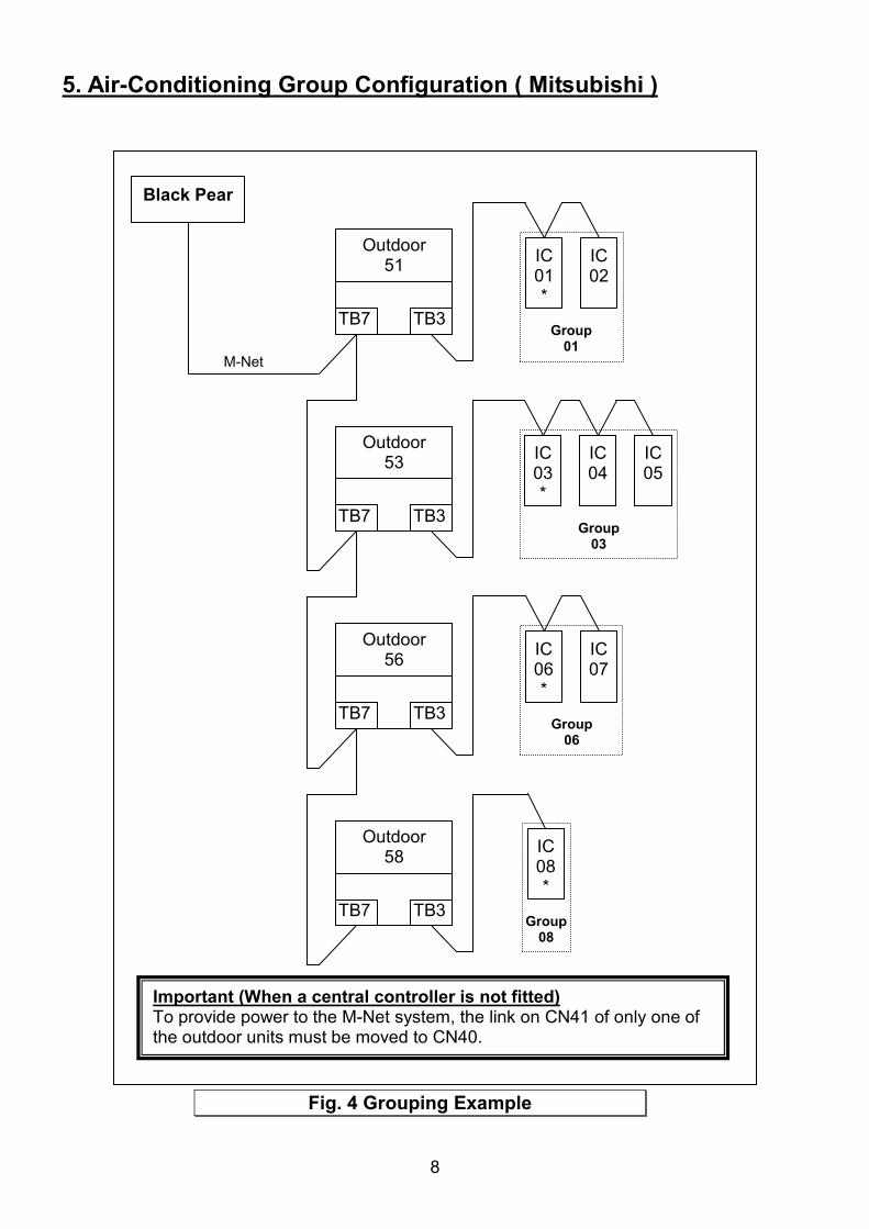
5. Air-Conditioning Group Configuration ( Mitsubishi )
IC 01 *
IC 02
Black Pear
Group 01
M-Net
IC 03 *
IC 04
IC 05
Group 03
IC 06 *
IC 07
Group 06
IC 08 *
Group 08
TB7 TB3
Outdoor 51
TB7 TB3
Outdoor 53
TB7 TB3
Outdoor 56
TB7 TB3
Outdoor 58
Important (When a central controller is not fitted)To provide power to the M-Net system, the link on CN41 of only one of the outdoor units must be moved to CN40.
Fig. 4 Grouping Example

9
The groupings determine which unit addresses can accept commands from the BMS system. The group number is defined as ‘the lowest indoor unit address within the group’. This then becomes the ‘master’ address for the group, and is the only address within that group that can accept commands. The other units within a group can be classed as ‘slave’ units and contain the same status parameter values as the ‘master’, apart from Return Air Temp and Error Code, which are unique to each unit. In the example shown in Fig 4, addresses 01, 03, 06 and 08 are the ‘master’ units, and 02, 04, 05 and 07 are the ‘slave’ units.
Attempting to write a command to a ‘slave’ unit will have no effect.
When a central controller is not fitted, the indoor unit grouping is handled by the Black Pear and is setup using the PC configuration software. If a group consists of multiple units and it is required to control these from a wall controller, then the wall controller must be linked to the relevant indoor units. See the HVAC manufacturers’ instructions for details. If a central controller is present on the system, the Black Pear will automatically discover the grouping information.

10
6. User Interface ( Display Version )
Navigation Buttons
Enter/Accept Button
Back/Cancel Button
Power LED
HVAC Network LED Flashes on a valid incoming message
BMS Network LED Flashes on a valid incoming message
Main Menu
System Overview Configuration
Modbus NetworkUnit
Status
Unit Control
Fig. 5 Screen Hierarchy

11
6.1 Main Menu
General Status Waiting… The Black Pear has been restarted and is preparing to start scanning the HVAC network.
Searching… The Black Pear is performing an initial scan to determine which unit addresses are active on the HVAC network. The progress bar shows how much of the scan has been performed.
Ready The initial scan is complete. Network Link N/C Not connected. Status ??? Auto-negotiation in progress.
10hd 10Mb half duplex 10fd 10Mb full duplex 100hd 100Mb half duplex 100fd 100Mb full duplex
USB Status <blank> Not connected USB Connected
HVAC Address 0 Fixed address when the Black Pear is acting as the central controller.
201 to 250 User configured address when a central controller is already present on the system.
Menu Selection
Use �,� and ����buttons to choose
Initial Scan Progress Bar
Network Link Status
USB Status
HVAC Address
Firmware Version
General Status

12
6.2 System Overview
Displays a grid showing the address of any unit discovered by the Black Pear, in the address range 1 to 50. Pressing the �� key will return to the Main Menu screen.
Selection Cursor. Controlled using the navigation buttons. Pressing ���� on a numbered cell will display the unit status screen.
A large number is a ‘Group Master’.
A small number is a ‘Slave Unit’.
An inverted number indicates the unit is ON.
A flashing number indicates the unit is in error.

13
6.3 Unit Status Screen
Group Master Status Screen
Slave Unit Status Screen
This screen shows the status of a single fan coil. Pressing the � or � key cycles backward and forward through all available fan coils. The �� key will return to the System Overview screen. Only a ‘Group Master’ will show a cursor to allow the current settings to be altered. Use the �,� and ���� keys to select a setting to be changed. The appropriate parameter setting window will be displayed. Use the �,� keys to choose a new setting, ���� to accept the change or �� to cancel the change.

7. Modbus Interface
7
RS232 / RS485
Black PearMM-50x
Outdoor Units Indoor Units
Modbus RTUBMS
System
Serial Comms cable
(Not supplied)
Ethernet
Modbus/TCPBMS
System
Cat-5 cable(Supplied)
M-Net
Fig. 6 Modbus System Example
14
.1 Port Configurations
RS232/RS485 interface Modbus RTU 9600 baud, 8 data bits, no parity, 1 stop bit Network interface Modbus/TCP 2 simultaneous Modbus/TCP client connections are supported: 1 only uses TCP port 502 (default Modbus/TCP port) 2 uses a user configurable TCP port number Modbus functions supported Fn 1 Read Coils Fn 3 Read Holding Registers Fn 5 Write Single Coil Fn 6 Write Single Register Fn 16 Write Multiple Registers (Max. 16 registers at once)
15
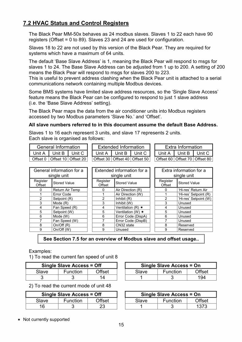
7.2 HVAC Status and Control Registers
The Black Pear MM-50x behaves as 24 modbus slaves. Slaves 1 to 22 each have 90 registers (Offset = 0 to 89). Slaves 23 and 24 are used for configuration. Slaves 18 to 22 are not used by this version of the Black Pear. They are required for systems which have a maximum of 64 units. The default ‘Base Slave Address’ is 1, meaning the Black Pear will respond to msgs for slaves 1 to 24. The Base Slave Address can be adjusted from 1 up to 200. A setting of 200 means the Black Pear will respond to msgs for slaves 200 to 223. This is useful to prevent address clashing when the Black Pear unit is attached to a serial communications network containing multiple Modbus devices. Some BMS systems have limited slave address resources, so the ‘Single Slave Access’ feature means the Black Pear can be configured to respond to just 1 slave address (i.e. the ‘Base Slave Address’ setting). The Black Pear maps the data from the air conditioner units into Modbus registers accessed by two Modbus parameters ‘Slave No.’ and ‘Offset’. All slave numbers referred to in this document assume the default Base Address. Slaves 1 to 16 each represent 3 units, and slave 17 represents 2 units. Each slave is organised as follows:
General Information Extended Information Extra Information Unit A Unit B Unit C Unit A Unit B Unit C Unit A Unit B Unit C Offset 0 Offset 10 Offset 20 Offset 30 Offset 40 Offset 50 Offset 60 Offset 70 Offset 80
General information for a single unit
Extended information for a single unit
Extra information for a single unit
Register Offset Stored Value Register
Offset Stored Value Register Offset Stored Value
0 Return Air Temp 0 Air Direction (R) 0 ‘Hi-res’ Return Air 1 Error Code 1 Air Direction (W) 1 ‘Hi-res’ Setpoint (R) 2 Setpoint (R) 2 Inhibit (R) 2 ‘Hi-res’ Setpoint (W)3 Mode (R) 3 Inhibit (W) 3 Unused 4 Fan Speed (R) 4 Ventilation (R) � 4 Unused 5 Setpoint (W) 5 Ventilation (W) � 5 Unused 6 Mode (W) 6 Error Code (DispA) 6 Unused 7 Fan Speed (W) 7 Error Code (DispB) 7 Unused 8 On/Off (R) 8 CN32 state 8 Reserved 9 On/Off (W) 9 Unused 9 Reserved
See Section 7.5 for an overview of Modbus slave and offset usage..
Examples: 1) To read the current fan speed of unit 8
Single Slave Access = Off Single Slave Access = On Slave Function Offset Slave Function Offset
3 3 14 1 3 194
2) To read the current mode of unit 48
Single Slave Access = Off Single Slave Access = On Slave Function Offset Slave Function Offset
16 3 23 1 3 1373
� Not currently supported

16
On/Off and Inhibit can also be accessed via ‘Coils’. Each slave contains 12 coils, organised as follows:
Coil Offset Definition
0 Unit A On/Off (R) 1 Unit A On/Off (W) 2 Unit B On/Off (R) 3 Unit B On/Off (W) 4 Unit C On/Off (R) 5 Unit C On/Off (W) 6 Unit A Inhibit (R) 7 Unit A Inhibit (W) 8 Unit B Inhibit (R) 9 Unit B Inhibit (W) 10 Unit C Inhibit (R) 11 Unit C Inhibit (W)
NoteCoil access is not available when ‘Single Slave Access’ is enabled.
7.3 Additional Register Usage
Slave Offset Single Slave Offset
Description Valid Settings
22 150 2040 HVAC Network Status 00: Waiting 01: Searching 02: Ready 03: Unknown
22 151 2041 System Force Off � 00: Not active 01: Active
See Section 9.5 for a description of the various settings.
� Not currently supported
17
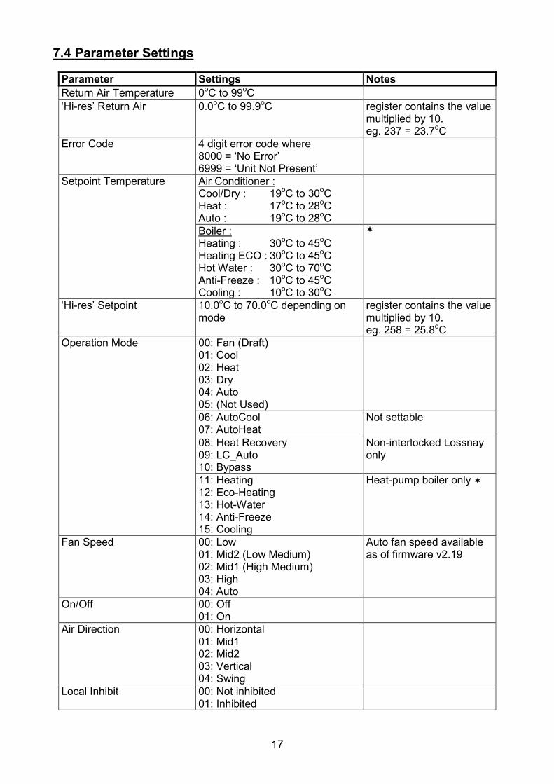
7.4 Parameter Settings
Parameter Settings Notes Return Air Temperature 0oC to 99oC‘Hi-res’ Return Air 0.0oC to 99.9oC register contains the value
multiplied by 10. eg. 237 = 23.7oC
Error Code 4 digit error code where 8000 = ‘No Error’ 6999 = ‘Unit Not Present’
Setpoint Temperature Air Conditioner :Cool/Dry : 19oC to 30oCHeat : 17oC to 28oCAuto : 19oC to 28oCBoiler :Heating : 30oC to 45oCHeating ECO : 30oC to 45oCHot Water : 30oC to 70oCAnti-Freeze : 10oC to 45oCCooling : 10oC to 30oC
�
‘Hi-res’ Setpoint 10.0oC to 70.0oC depending on mode
register contains the value multiplied by 10. eg. 258 = 25.8oC
Operation Mode 00: Fan (Draft) 01: Cool 02: Heat 03: Dry 04: Auto 05: (Not Used)
06: AutoCool 07: AutoHeat
Not settable
08: Heat Recovery 09: LC_Auto 10: Bypass
Non-interlocked Lossnay only
11: Heating 12: Eco-Heating 13: Hot-Water 14: Anti-Freeze 15: Cooling
Heat-pump boiler only �
Fan Speed 00: Low 01: Mid2 (Low Medium) 02: Mid1 (High Medium) 03: High 04: Auto
Auto fan speed available as of firmware v2.19
On/Off 00: Off 01: On
Air Direction 00: Horizontal 01: Mid1 02: Mid2 03: Vertical 04: Swing
Local Inhibit 00: Not inhibited 01: Inhibited
18
Parameter Settings Notes Ventilation 00: Off
01: Low 02: High
Interlocked Lossnay / OA units only �
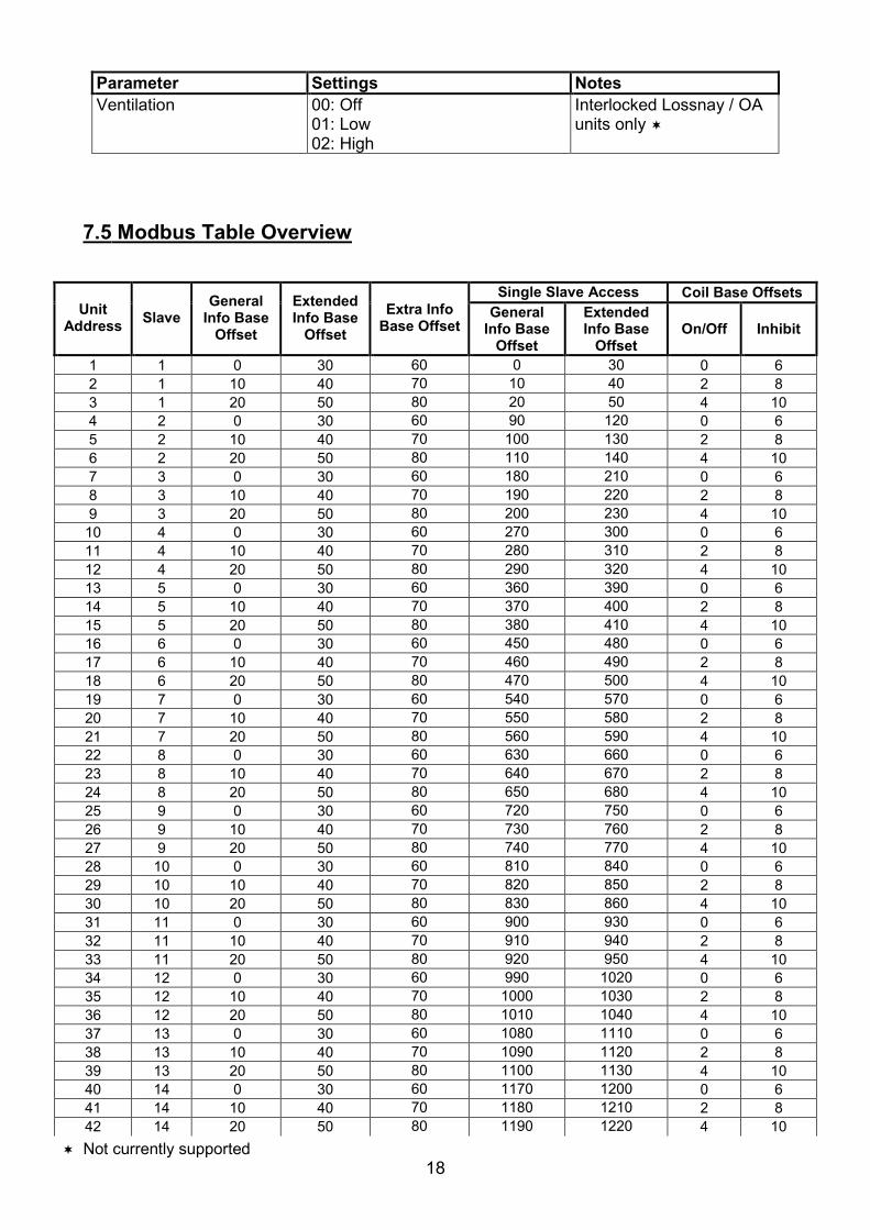
7.5 Modbus Table Overview
Single Slave Access Coil Base Offsets Unit
Address Slave General
Info Base Offset
Extended Info Base
Offset
Extra Info Base Offset
General Info Base
Offset
Extended Info Base
Offset On/Off Inhibit
1 1 0 30 60 0 30 0 62 1 10 40 70 10 40 2 83 1 20 50 80 20 50 4 10 4 2 0 30 60 90 120 0 65 2 10 40 70 100 130 2 86 2 20 50 80 110 140 4 10 7 3 0 30 60 180 210 0 68 3 10 40 70 190 220 2 89 3 20 50 80 200 230 4 10 10 4 0 30 60 270 300 0 611 4 10 40 70 280 310 2 812 4 20 50 80 290 320 4 10 13 5 0 30 60 360 390 0 614 5 10 40 70 370 400 2 815 5 20 50 80 380 410 4 10 16 6 0 30 60 450 480 0 617 6 10 40 70 460 490 2 818 6 20 50 80 470 500 4 10 19 7 0 30 60 540 570 0 620 7 10 40 70 550 580 2 821 7 20 50 80 560 590 4 10 22 8 0 30 60 630 660 0 623 8 10 40 70 640 670 2 824 8 20 50 80 650 680 4 10 25 9 0 30 60 720 750 0 626 9 10 40 70 730 760 2 827 9 20 50 80 740 770 4 10 28 10 0 30 60 810 840 0 629 10 10 40 70 820 850 2 830 10 20 50 80 830 860 4 10 31 11 0 30 60 900 930 0 632 11 10 40 70 910 940 2 833 11 20 50 80 920 950 4 10 34 12 0 30 60 990 1020 0 635 12 10 40 70 1000 1030 2 836 12 20 50 80 1010 1040 4 10 37 13 0 30 60 1080 1110 0 638 13 10 40 70 1090 1120 2 839 13 20 50 80 1100 1130 4 10 40 14 0 30 60 1170 1200 0 641 14 10 40 70 1180 1210 2 842 14 20 50 80 1190 1220 4 10
� Not currently supported

19
Single Slave Access Coil Base Offsets Unit
Address Slave General
Info Base Offset
Extended Info Base
Offset
Extra Info Base Offset
General Info Base
Offset
Extended Info Base
Offset On/Off Inhibit
43 15 0 30 60 1260 1290 0 644 15 10 40 70 1270 1300 2 845 15 20 50 80 1280 1310 4 10 46 16 0 30 60 1350 1380 0 647 16 10 40 70 1360 1390 2 848 16 20 50 80 1370 1400 4 10 49 17 0 30 60 1440 1470 0 650 17 10 40 70 1450 1480 2 8

20
8. Trend Interface (MT-50x only)
The Black Pear connects via Ethernet to a CNC or the virtual CNC port of a Trend IQ outstation, and uses sensors, switches and knobs defined in the IQx memory to mirror a range of HVAC parameters, making them available on a Trend network.
Black PearMT-50x
Outdoor Units Indoor Units
Ethernet
Trend IQx Outstation with vCNC
Cat-5 cable(Supplied)
M-Net
Trend Supervisor
Fig. 7 Trend System Example

21
8.1 Trend Process Description
Startup Sequence 1) Power up 2) Waiting for initial scan 3) Perform initial HVAC scan 4) Initial scan complete 5) Connect to CNC port 6) Transfer current HVAC status to required Trend outstation (“First Pass”) 7) Disconnect from CNC port 8) Wait for re-connection time 9) Connect to CNC port 10) Poll the objects for each active HVAC unit in the Trend outstation, then either Update the HVAC if the value of a Trend object has been altered, or Update the Trend object if the value of an HVAC parameter has changed. 11) Disconnect from CNC port 12) Wait for re-connection time 13) Goto 9 At power-up, the Black Pear will wait for the initial HVAC scan to begin. During this scan, all available ‘active’ HVAC units are discovered. Once the scan is complete, the Black Pear will transfer all current parameter settings to the appropriate objects in the destination Trend outstation. This process is called the ‘First Pass’. This ensures that the values in the Black Pear and the Trend device are in sync. Until the ‘First Pass’ is complete, all commands sent from the Trend network to the Black Pear will be ignored. The re-connection time is calculated from the CNC Usage setting within the Black Pear. This ensures that all Black Pear devices sharing a single CNC have enough time to connect. Notes:� Some Trend systems will generate ‘network alarms’ due to the repeated connection and disconnection of the Black Pear to the CNC. Setting the CNC Usage = 0 will allow a single Black Pear to remain connected to the CNC, thus preventing these alarms from being generated. This feature was added in firmware v2.19.
Following a reconfiguration of the Trend outstation, it is important that the Black Pear is restarted, to guarantee that all parameters are
in sync.

22
8.2 Trend IQx Outstation Configuration
3 sensors, 2 switches and 4 knobs are required to store all the parameters for a single unit. The table below shows how to calculate the number of each object required :
Fan Coil Parameter Sensor No. Switch No. Knob No.
Return Air S+((FC-1)*3) Error Code S+((FC-1)*3)+1 CN32 State S+((FC-1)*3)+2 On/Off W+((FC-1)*2) Inhibit W+((FC-1)*2)+1 Setpoint K+((FC-1)*4) Mode K+((FC-1)*4)+1 Fan Speed K+((FC-1)*4)+2 Air Direction K+((FC-1)*4)+3
where FC = Fan Coil Address (1 to 50) S = Sensor Base Address W = Switch Base Address Set using configuration software K = Knob Base Address E.g. If Sensor Base Address =100 Switch Base Address = 50 Knob Base Address = 50 then the following table shows the object numbers required for addresses 1,2,49 and 50.
FC 1 FC 2 ….. FC 49 FC 50
Sensors 100 to 102 103 to 105 ….. 244 to 246 247 to 249 Switches 50 to 51 52 to 53 ….. 146 to 147 148 to 149 Knobs 50 to 53 54 to 57 ….. 242 to 245 246 to 249
The Black Pear can be configured to enable only those objects of interest to the user, therefore reducing the memory overhead required in the IQ outstation. Any objects enabled in the Black Pear which aren’t defined in the Trend outstation will simply be ignored during the polling sequence. Note that this does not change the sensor, switch and knob numbers associated with each HVAC parameter.
If a sensor has been added to the sequence table then its ‘Value’ output must be connected to its ‘Source Value’ input, otherwise it will
return a reading of zero.
See Appendix C for details of the memory requirements in the Trend outstation.
}

23
8.3 Parameter Settings
See the table in Section 7.4 for a list of valid parameter settings. Notes:� As of firmware v2.29, the return air sensor and the setpoint knob will contain temperatures valid to 1 dp. Setting the setpoint to 1 dp is reliant on the HVAC unit accepting setpoint commands to this resolution.

24
9.BACnet Interface (MB-50x only)
The BLACK Pear MB-50x is designed to work with a BACnet/IP network as described in the ANSI/ASHRAE Standard 135-2004.
Property Setting Segmentation Not Supported Maximum APDU length supported 206 octets Object List Supported Device ID User settable (1) Device Name User settable (1) Object Names User settable (1)
Notes: (1) Only settable via PC configuration program.
Black PearMB-50x
Outdoor Units Indoor Units
BACnet / IPEthernet
BACnet BMS
System
Cat-5 cable(Supplied)
M-Net
Fig. 8 BACnet System Example

25
9.1 Object Types
Object Type Supported
Analog Input 0 Yes Analog Output 1 Yes Analog Value 2 Binary Input 3 Yes Binary Output 4 Yes Binary Value 5 Yes Calendar 6 Command 7 Device 8 Yes Event Enrollment 9 File 10 Group 11 Loop 12 Multi-State Input 13 Yes Multi-State Output 14 Yes Notification Class 15 Program 16 Schedule 17 Averaging 18 Multi-State Value 19 Trend Log 20
9.2 Service List
Supported Services
Read Property 12 Read Property Multiple 14 Write Property 15 Write Property Multiple 16 Who-Has 33 I-Have 27 Who-Is 34 I-Am 36
26
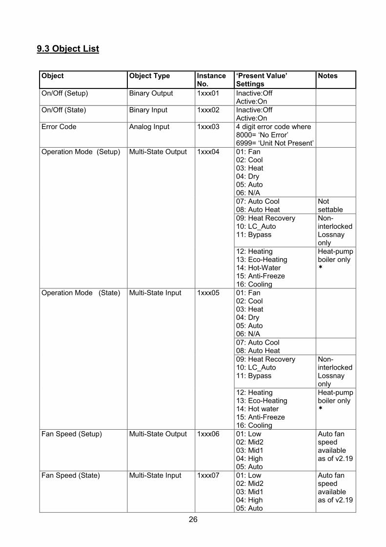
9.3 Object List
Object Object Type Instance No.
‘Present Value’ Settings
Notes
On/Off (Setup) Binary Output 1xxx01 Inactive:Off Active:On
On/Off (State) Binary Input 1xxx02 Inactive:Off Active:On
Error Code Analog Input 1xxx03 4 digit error code where8000= ‘No Error’ 6999= ‘Unit Not Present’
Operation Mode (Setup) Multi-State Output 1xxx04 01: Fan 02: Cool 03: Heat 04: Dry 05: Auto 06: N/A
07: Auto Cool 08: Auto Heat
Not settable
09: Heat Recovery 10: LC_Auto 11: Bypass
Non-interlocked Lossnay only
12: Heating 13: Eco-Heating 14: Hot-Water 15: Anti-Freeze 16: Cooling
Heat-pump boiler only�
Operation Mode (State) Multi-State Input 1xxx05 01: Fan 02: Cool 03: Heat 04: Dry 05: Auto 06: N/A
07: Auto Cool 08: Auto Heat
09: Heat Recovery 10: LC_Auto 11: Bypass
Non-interlocked Lossnay only
12: Heating 13: Eco-Heating 14: Hot water 15: Anti-Freeze 16: Cooling
Heat-pump boiler only�
Fan Speed (Setup) Multi-State Output 1xxx06 01: Low 02: Mid2 03: Mid1 04: High 05: Auto
Auto fan speed available as of v2.19
Fan Speed (State) Multi-State Input 1xxx07 01: Low 02: Mid2 03: Mid1 04: High 05: Auto
Auto fan speed available as of v2.19

27
Object Object Type Instance No.
‘Present Value’ Settings
Notes
Room Temperature Analog Input 1xxx08
�
Setpoint Temperature (Setup)
Analog Output 1xxx09 Cool/Dry : 19oC to 30oCHeat : 17oC to 28oCAuto : 19oC to 28oC
�
Boiler : 10oC to 70oC ��Setpoint Temperature (State)
Analog Input 1xxx10 Cool/Dry : 19oC to 30oCHeat : 17oC to 28oCAuto : 19oC to 28oC
�
Boiler : 10oC to 70oC ��Local Inhibit (Setup) Binary Output 1xxx11 Inactive:Off
Active:Inhibit
Local Inhibit (State) Binary Input 1xxx12 Inactive:Off Active:Inhibited
Air Direction (Setup) Multi-State Output 1xxx13 01: Horizontal 02: Mid1 03: Mid2 04: Vertical 05: Swing
Air Direction (State) Multi-State Input 1xxx14 01: Horizontal 02: Mid1 03: Mid2 04: Vertical 05: Swing
Ventilation (Setup) Multi-State Output 1xxx15 01: Off 02: Low 03: High
Interlocked Lossnay / OA units only �
Ventilation (State) Multi-State Input 1xxx16 01: Off 02: Low 03: High
Interlocked Lossnay / OA units only �
CN32 (State) Analog Input 1xxx17 0-3 Appendix D
(Unused) 1xxx18 (Unused) 1xxx19 (Unused) 1xxx20 (Unused) 1xxx21 (Unused) 1xxx22 HVAC Network Status Multi-State Input 100023 01: Waiting
02: Searching 03: Ready 04: Unknown
System Force Off Binary Value 100024 Inactive:Off Active:On
�
Device Device zzz zzz = 1 to 4194302
where xxx represents unit address 001 to 050

28
9.4 Object Names
Object Object Name Notes On/Off (Setup) nnn (ON_w) On/Off (State) nnn (ON_r) Error Code nnn (ECode) Operation Mode (Setup) nnn (MD_w) Operation Mode (State) nnn (MD_r) Fan Speed (Setup) nnn (FS_w) Fan Speed (State) nnn (FS_r) Room Temperature nnn (RA) �Setpoint Temperature (Setup) nnn (SP_w) �Setpoint Temperature (State) nnn (SP_r) �Local Inhibit (Setup) nnn (LI_w Local Inhibit (State) nnn (LI_r) Air Direction (Setup) nnn (AD_w) Air Direction (State) nnn (AD_r) Ventilation (Setup) nnn (VN_w) Interlocked
Lossnay / OA units only �
Ventilation (State) nnn (VN_r) Interlocked Lossnay / OA units only �
CN32 (State) nnn (CN32) HVAC Network Status Sys_HVAC_Network_Status System Force Off Sys_Force_Off
where ‘nnn’ is the unit name entered via the configuration program.
� As of firmware v2.29, the room temperature object and the setpoint read and write objects will contain temperatures valid to 1 dp. Setting the setpoint to 1 dp is reliant on the HVAC unit accepting setpoint commands to this resolution.
� Not currently supported
� Not currently supported
29
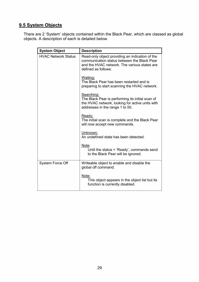
9.5 System Objects
There are 2 ‘System’ objects contained within the Black Pear, which are classed as global objects. A description of each is detailed below.
System Object Description HVAC Network Status Read-only object providing an indication of the
communication status between the Black Pear and the HVAC network. The various states are defined as follows: Waiting:The Black Pear has been restarted and is preparing to start scanning the HVAC network. Searching:The Black Pear is performing its initial scan of the HVAC network, looking for active units with addresses in the range 1 to 50. Ready:The initial scan is complete and the Black Pear will now accept new commands. Unknown:An undefined state has been detected. Note:
Until the status = ‘Ready’, commands send to the Black Pear will be ignored.
System Force Off Writeable object to enable and disable the
global off command. Note:
This object appears in the object list but its function is currently disabled.
30
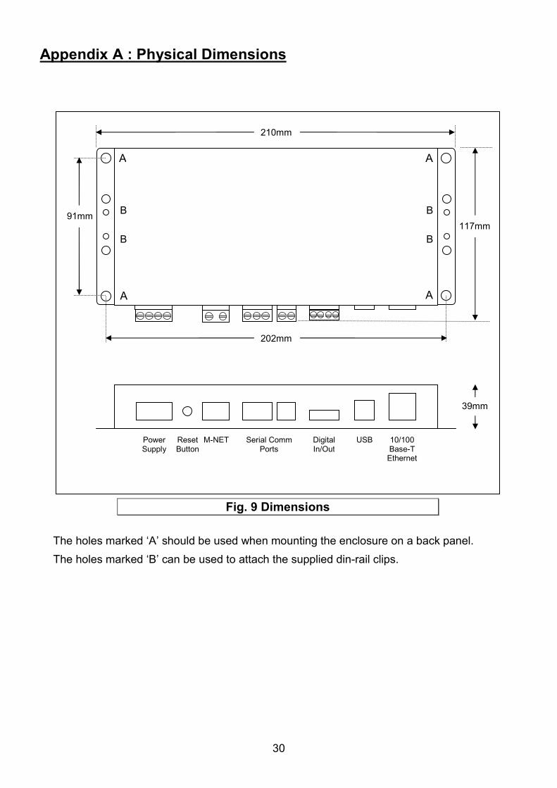
Appendix A : Physical Dimensions
The holes marked ‘A’ should be used when mounting the enclosure on a back panel. The holes marked ‘B’ can be used to attach the supplied din-rail clips.
117mm
ResetButton
PowerSupply
M-NET Serial Comm Ports
Digital In/Out
USB 10/100 Base-T
Ethernet
210mm
202mm
39mm
A
A
A
A
B
B
B
B
91mm
Fig. 9 Dimensions
31
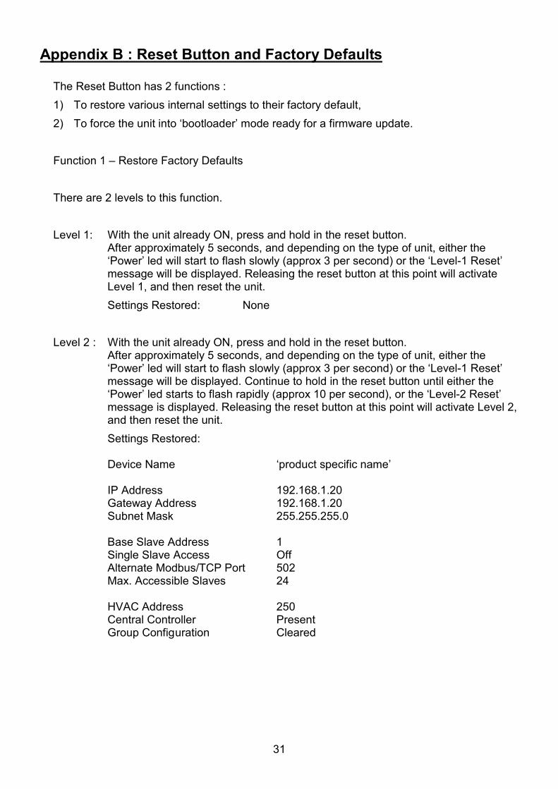
Appendix B : Reset Button and Factory Defaults
The Reset Button has 2 functions : 1) To restore various internal settings to their factory default, 2) To force the unit into ‘bootloader’ mode ready for a firmware update. Function 1 – Restore Factory Defaults There are 2 levels to this function. Level 1: With the unit already ON, press and hold in the reset button.
After approximately 5 seconds, and depending on the type of unit, either the ‘Power’ led will start to flash slowly (approx 3 per second) or the ‘Level-1 Reset’ message will be displayed. Releasing the reset button at this point will activate Level 1, and then reset the unit.
Settings Restored: None Level 2 : With the unit already ON, press and hold in the reset button.
After approximately 5 seconds, and depending on the type of unit, either the ‘Power’ led will start to flash slowly (approx 3 per second) or the ‘Level-1 Reset’ message will be displayed. Continue to hold in the reset button until either the ‘Power’ led starts to flash rapidly (approx 10 per second), or the ‘Level-2 Reset’ message is displayed. Releasing the reset button at this point will activate Level 2, and then reset the unit.
Settings Restored:
Device Name ‘product specific name’
IP Address 192.168.1.20 Gateway Address 192.168.1.20 Subnet Mask 255.255.255.0
Base Slave Address 1 Single Slave Access Off Alternate Modbus/TCP Port 502 Max. Accessible Slaves 24
HVAC Address 250 Central Controller Present Group Config uration Cleared

32
Additional Settings Restored for Trend Interfaces (MT-50x): Pin Code Disabled Sensor Base Address 100 Switch Base Address 50 Knob Base Address 50
Object Enable Mask All Objects Enabled OutStation Address 2 CNC IP Address 192.168.1.1 CNC Address 1 CNC Port Number 10001 CNC Usage 1 Additional Settings Restored for BACnet Interfaces (MB-50x): Device ID 200 UDP Port 47808 New Setting Comparison Disabled Register as Foreign Device Disabled Foreign Device Reg TTL 1800 seconds Preserve PVs & PAs Disabled Input PV -> Output PV Disabled Function 2 – Enable ‘Bootloader’ Mode Bootloader mode allows the firmware to be updated from a PC. Press and hold in the reset button while powering up the unit. Continue to hold in the reset button for approx. 5 seconds. The unit is now in bootloader mode.
Note:Enabling the bootloader in this way is only necessary if the firmware update software fails to automatically put the unit into bootloader mode.

33
Appendix C : Trend Outstation Memory Usage (MT-50x only)
1) The table below shows how much memory (in brIQs) each parameter requires :
Parameter Trend Module Size (brIQs) Comments Return Air Temp Sensor 76
Error Code Sensor 76
CN32 state Sensor 76 Mitsubishi Only
On/Off Switch 10
Inhibit Switch 10
Setpoint Knob 13
Mode Knob 13
Fan Speed Knob 13
Air Direction Knob 13
2) A Trend IQ3 has a capacity of 10000 to 45000 brIQs depending on the model and an IQ41x has a capacity of 10000 brIQs.
3) This table shows the number of brIQs needed for various system sizes and parameter requirements:
Parameter Usage brIQs per
FC 10 FC
system 25 FC
system 50 FC
system
All parameters (Mitsubishi) 300 3000 7500 15000
Return Air Error Code 152 1520 3800 7600
Return Air Error code On/Off Setpoint
175 1750 4375 8750
Return Air Error Code On/Off Inhibit Setpoint Mode Fan Speed
211 2110 5275 10550
IQ3xcite IQ3xact IQ3xcite IQ41x I/O Max 0 12 16 96 128 IQ3 brIQs - 10,000 30,000 30,000 37,000 - IQ3/XNC brIQs 45,000 20,000 - 45,000 - - IQ41x brIQs 10,000

34
4) This table shows the absolute maximum number of FCs which can be stored in various Trend outstations.
Parameter
Usage IQ3xcite/
XNC IQ3xact IQ3xact/
XNC IQ3xcite/
16 IQ3xcite/
96 IQ3xcite/
128 IQ41x
All parameters (Mitsubishi) 150 33 66 100 100 123 33
Return Air Error Code 296 65 131 197 197 243 65
Return Air Error code On/Off Setpoint
257 57 114 171 171 211 57
Return Air Error Code On/Off Inhibit Setpoint Mode Fan Speed
213 47 94 142 142 175 47
Note: 1) When calculating the number of outstations required for a system, it is recommended to allow some spare capacity for strategy and other configuration data. 2) A single Black Pear device can only communicate with 1 Trend outstation, but multiple Black Pears can communicate with the same Trend outstation, provided there is enough memory in the Trend unit.

35
Appendix D : CN32 Connector
The CN32 connector on an indoor unit has 2 digital inputs which are normally used for remote operation via an external switch or timer. Setting SW1-9 ON and SW1-10 ON disables the remote operation functionality and converts CN32 into general purpose digital inputs.
The register ‘CN32 State’ for each indoor unit will contain the following values depending on the state of SW1 and SW2 :
Register Value SW1 State SW2 State 0 Open Open 1 Closed Open 2 Open Closed 3 Closed Closed
Orange
Red
Brown
Indoor Unit Circuit Board
CN32 SW1
SW2
3-wire adapter cable
SW1 and SW2 are volt-free contacts
123
Fig. 10 CN32 Connection Diagram

36
Appendix E : Document Revision History
Date Document Ver Firmware Ver By Comments 05/08/2013 v1.00 v2.03 mcb First complete version.
06/08/2013 v1.01 v2.03 mcb Added various clarifications. 04/11/2013 v1.02 v2.11 mcb Non-interlocked Lossnay modes now
supported. ‘Max. Accessible Slaves’ added to Factory Reset list.
22/05/2014 v1.03 v2.18 mcb Important Information now includes comment about configuration software.
29/05/2014 v1.04 v2.19 mcb Added support for ‘Auto’ fan speed setting. Added description of how to permanently connect to Trend CNC.
11/07/2014 v1.05 v2.22 mcb added CN32 to BACnet object list 23/04/2015 v1.06 v2.27 mcb updated section 4.4 to describe ‘Global
Forced Off’ feature. 11/11/2015 v1.07 v2.29 mcb Modbus registers now include ‘hi-res’
RA and SP. Trend and BACnet sections now mention ‘hi-res’ RA and SP.
23/12/2015 v1.08 v2.30 mcb Corrected mode list in BACnet object table.

Notes

Microtrol Ltd 16 Elgar Business Centre Moseley Road Hallow Worcester WR2 6NJ UK Tel: +44 (0)1905 641910 Email: [email protected]