(bmw e39 gm p16)gm 5l40e atsg repair manual
TRANSCRIPT
INDEX
Copyright © ATSG 2002
HYDRA-MATIC 4L40-E/5L40-E
2
AUTOMATIC TRANSMISSION SERVICE GROUP9200 S. DADELAND BLVD. SUITE 720
MIAMI, FLORIDA 33156(305) 670-4161
5L40-E IDENTIFICATION TAG INFORMATION .......................................................................................... 3CUT-AWAY VIEW AND COOLER LINE IDENTIFICATION ........................................................................ 4COMPONENT APPLICATION CHART .......................................................................................................... 5SOLENOID APPLICATION AND RESISTANCE CHARTS ........................................................................... 6INTERNAL WIRE SCHEMATIC ..................................................................................................................... 7TCM LOCATION, CONNECTOR I.D. AND UNDERHOOD FUSE BLOCK I.D. ........................................ 8ELECTRONIC COMPONENT LOCATER ....................................................................................................... 10INTERNAL MODE SWITCH DESCRIPTION ............. ................................................................................... 11DIAGNOSTIC TROUBLE CODES AND DESCRIPTION ............................................................................... 12GENERAL OPERATION AND DESCRIPTION ............. ................................................................................. 14FLUID LEVEL CHECKING PROCEDURE .................................................................................................... 15LINE PRESSURE TESTS .................................................................................................................................. 16OIL PRESSURE PASSAGE IDENTIFICATIONS ........................................................................................... 17CHECK BALL DESCRIPTIONS ....................................................................................................................... 24TRANSMISSION DISASSEMBLY .................................................................................................................... 27TRANSMISSION EXPLODED VIEW .............................................................................................................. 30COMPONENT REBUILD SECTION......... CASE ASSEMBLY .......................................................................................................................................... 41 OIL PUMP ASSEMBLY .................................................................................................................................. 45 DIRECT AND REVERSE CLUTCH HOUSING ........................................................................................... 51 FORWARD AND COAST CLUTCH HOUSING ........................................................................................... 59 FORWARD SPRAG ASSEMBLY ................................................................................................................... 67 INTERMEDIATE SPRAG ASSEMBLY ........................................................................................................ 69 INTERMEDIATE AND OVERDRIVE CLUTCH HOUSING ...................................................................... 76 LOW SPRAG ASSEMBLY .............................................................................................................................. 81 CENTER SUPPORT ASSEMBLY ................................................................................................................. 84 5L40-E PLANETARY CARRIER ASSEMBLY .............................................................................................. 96 4L40-E PLANETARY CARRIER ASSEMBLY .............................................................................................. 99 VALVE BODY ASSEMBLY ............................................................................................................................ 102 CHECKBALL LOCATIONS .......................................................................................................................... 105FINAL TRANSMISSION ASSEMBLY ............................................................................................................ 108BOLT IDENTIFICATION CHART ................................................................................................................. 126TORQUE SPECIFICATIONS .......................................................................................................................... 127
"Portions of materials contained herein have been reprinted withpermission of General Motors Corporation, Service Operations."
"Portions of materials contained herein have been reprinted withpermission of General Motors Corporation, Service Operations."
The information and part numbers contained in this booklet havebeen carefully compiled from industry sources known for their
reliability, but ATSG does not guarantee its accuracy.
Copyright © ATSG 2002
INTRODUCTION
AUTOMATIC TRANSMISSION SERVICE GROUP9200 S. DADELAND BLVD. SUITE 720
MIAMI, FLORIDA 33156(305) 670-4161
HYDRA-MATIC 4/5L40-E
1
No part of any ATSG publication may be reproduced, stored in any retrieval system or transmitted in any form or by any means, including but not limited to electronic, mechanical, photocopying, recording or otherwise, without written permission of Automatic Transmission Service Group. This includes all text illustrations, tables and charts.
Beginning at the start of production for some 1999 models, BMW has introduced a new 5 speed automatic transmission that is designed and manufactured by General Motors Powertrain division in Strasbourg, France and is illustrated in Figure 1. This new transmission is designated as follows:
GM Designation - 5L40-E BMW Designation - A5S 360R
Model year 1999 applications are as follows:
Model year 2003 applications are as follows:
3 Series BMW, with 2.5L Gasoline Engine, Used in USA and Japan.3 Series BMW, with 2.8L Gasoline Engine, Used in USA and Japan.5 Series BMW, with 3.0L Diesel Engine, Used Worldwide.
Cadillac CTS model, Gasoline Engine, Used Worldwide
DALE ENGLANDFIELD SERVICE CONSULTANT
ED KRUSETECHNICAL CONSULTANT
WAYNE COLONNATECHNICAL SUPERVISOR
PETER LUBANTECHNICAL CONSULTANT
JIM DIALTECHNICAL CONSULTANT
GREGORY LIPNICKTECHNICAL CONSULTANT
JERRY GOTTTECHNICAL CONSULTANT
JON GLATSTEINTECHNICAL CONSULTANT
DAVID CHALKERTECHNICAL CONSULTANT
STANTON ANDERSONTECHNICAL CONSULTANT
ROLAND ALVAREZTECHNICAL CONSULTANT
GERALD CAMPBELLTECHNICAL CONSULTANT
PublishedJuly, 2002
GMHYDRAMATIC
STRASBOURG
FRANCEHYDRAMATIC
STRASBOURG
FRANCE
*0139781RVO*
*0139781RVO*
96 02296 022 832
18/12/99 019971
18:54
1423875
P08
0139978196022832
VO
GMGM
CUSTOMERPART NUMBER
HYDRAMATICPART NUMBER
SERIALNUMBER
CALIBRATION
BROADCASTCODE
HYDRAMATICSTRASBOURGMADE IN FRANCE
SERIAL NO.
1 423 875
0139781
9 6 0 2 2 8 3 2
P08
VO_ _
PART NO.
TCMCAL.
GM
AUTOMATIC TRANSMISSION SERVICE GROUP
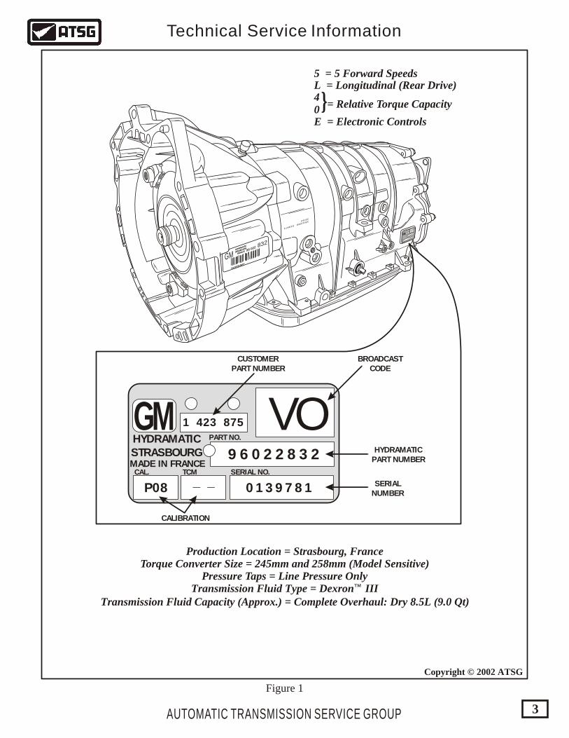
Technical Service Information
3
Copyright © 2002 ATSG
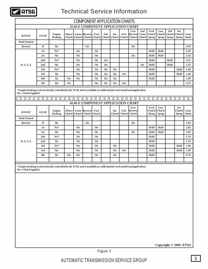
5 = 5 Forward Speeds
= Relative Torque Capacity
L = Longitudinal (Rear Drive)
E = Electronic Controls
40}
Figure 1
Production Location = Strasbourg, FranceTorque Converter Size = 245mm and 258mm (Model Sensitive)
Pressure Taps = Line Pressure OnlyTransmission Fluid Type = Dexronä III
Transmission Fluid Capacity (Approx.) = Complete Overhaul: Dry 8.5L (9.0 Qt)
AUTOMATIC TRANSMISSION SERVICE GROUP
Technical Service Information
4
Copyright © 2002 ATSG
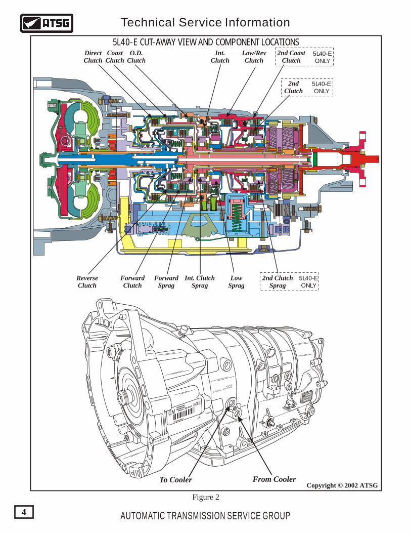
5L40-E CUT-AWAY VIEW AND COMPONENT LOCATIONS
Figure 2
DirectClutch
CoastClutch
O.D.Clutch
Int.Clutch
Low/RevClutch
2nd CoastClutch
2ndClutch
ReverseClutch
ForwardClutch
ForwardSprag
Int. ClutchSprag
2nd ClutchSprag
LowSprag
5L40-EONLY
5L40-EONLY
5L40-EONLY
GMHYDRAMATIC
STRASBOURG
FRANCEHYDRAMATIC
STRASBOURG
FRANCE
*0139781RVO*
*0139781RVO*
96 02296 022 832
18/12/99 019971
18:54
1423875
P08
0139978196022832
VO
GMGM
To Cooler From Cooler
AUTOMATIC TRANSMISSION SERVICE GROUP
Technical Service Information
5
Copyright © 2002 ATSG
DirectClutch
RANGE
4L40-E COMPONENT APPLICATION CHART
Park/Neutral
Reverse
D, 4, 3, 2,
GEAR
R
1st
1st
2nd
2nd
3rd
3rd
4th
EngineBraking
Yes
Yes
Yes
Yes
Yes On
On
On
On
On
On On
Hold
Hold
Hold
Hold
Hold Hold
Hold
Hold
HoldHold
Hold
On
On
On
On
On
On
On
On
On
On
On
On
On
On
No*
No*
No*
CoastClutch
On
O.D.Clutch
Int.Clutch
Low/ReverseClutch
GearRatio
2.82
2.82
1.54
1.54
1.00
1.00
0.70
3.03
ReverseClutch
Fwd.Clutch
Fwd.ClutchSprag
Int.ClutchSprag
LowClutchSprag
* Engine braking is electronically controlled by the TCM, and is available as calibrated for each model and application.On = Clutch Applied.
DirectClutch
RANGE
5L40-E COMPONENT APPLICATION CHART
Park/Neutral
Reverse
D, 4, 3, 2,
GEAR
R
1st
1st
2nd
2nd
3rd
3rd
4th
5th
EngineBraking
Yes
Yes
Yes
Yes
Yes On
On
On
On
On
On
On On
On
On On
Hold
Hold
Hold
Hold
Hold Hold
Hold
Hold
Hold
Hold
HoldHold
Hold
On
On
On
On
On
On
On
On
On
On
On
On
On
On
On
On
On
On
On
On
Yes
No*
No*
No*
CoastClutch
On
On
O.D.Clutch
Int.Clutch
Low/ReverseClutch
2ndCoastClutch
GearRatio
3.42
3.42
2.21
2.21
1.60
1.60
1.00
0.75
3.03
2ndClutch
ReverseClutch
Fwd.Clutch
Fwd.ClutchSprag
Int.ClutchSprag
2ndClutchSprag
LowClutchSprag
* Engine braking is electronically controlled by the TCM, and is available as calibrated for each model and application.On = Clutch Applied.
COMPONENT APPLICATION CHARTS
Figure 3
AUTOMATIC TRANSMISSION SERVICE GROUP
Technical Service Information
6
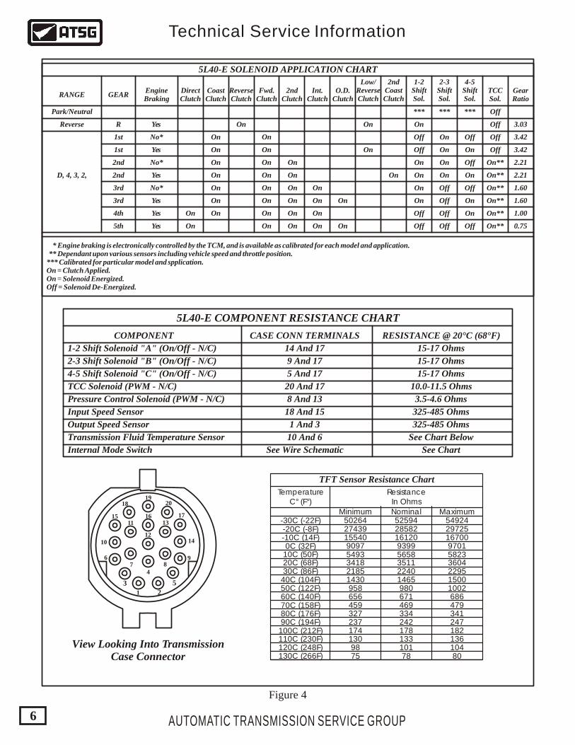
DirectClutch
RANGE
5L40-E SOLENOID APPLICATION CHART
Park/Neutral
Reverse
D, 4, 3, 2,
GEAR
R
1st
1st
2nd
2nd
3rd
3rd
4th
5th
EngineBraking
Yes
Yes
Yes
Yes
Yes On
On
On
On
On
On
On On
On
On On
On
On
On
On
On
On
On
On
On
Off
Off
Off
Off
Off
Off
Off
Off
Off
Off
Off
Off
On
On
On
On
*** *** *** Off
Off
Off
Off
On**
On**
On**
On**
On**
On**
On
On
On
On
On
On
On
On
On
On
On
On
On
On
On
On
On
On
On
On
Yes
No*
No*
No*
CoastClutch
On
On
O.D.Clutch
Int.Clutch
Low/ReverseClutch
2ndCoastClutch
GearRatio
3.42
3.42
2.21
2.21
1.60
1.60
1.00
0.75
3.03
2ndClutch
ReverseClutch
Fwd.Clutch
1-2ShiftSol.
TCCSol.
4-5ShiftSol.
2-3ShiftSol.
* Engine braking is electronically controlled by the TCM, and is available as calibrated for each model and application. ** Dependant upon various sensors including vehicle speed and throttle position.*** Calibrated for particular model and spplication.On = Clutch Applied.On = Solenoid Energized.Off = Solenoid De-Energized.
5L40-E COMPONENT RESISTANCE CHART
1-2 Shift Solenoid "A" (On/Off - N/C)
COMPONENT CASE CONN TERMINALS RESISTANCE @ 20°C (68°F)
15-17 Ohms
15-17 Ohms
15-17 Ohms
325-485 Ohms
325-485 Ohms
See Chart Below
See ChartSee Wire Schematic
14 And 17
9 And 17
5 And 17
20 And 17
8 And 13
18 And 15
1 And 3
10 And 6
10.0-11.5 Ohms
3.5-4.6 Ohms
2-3 Shift Solenoid "B" (On/Off - N/C)
4-5 Shift Solenoid "C" (On/Off - N/C)
TCC Solenoid (PWM - N/C)
Pressure Control Solenoid (PWM - N/C)
Input Speed Sensor
Output Speed Sensor
Transmission Fluid Temperature Sensor
Internal Mode Switch
23 5
48
9
10
11
12
13
20
1715 16
1819
14
76
1
View Looking Into TransmissionCase Connector
54924502642743915540909754933418218514309586564593272371741309875 78 80
101 104133 136178 182242 247334 341469 479671 686980 10021465 15002240 22953511 36045658 58239399 970116120 1670028582 29725
-30C (-22F)-20C (-8F)-10C (14F)0C (32F)10C (50F)20C (68F)30C (86F)40C (104F)50C (122F)60C (140F)70C (158F)80C (176F)90C (194F)100C (212F)110C (230F)120C (248F)130C (266F)
52594
TemperatureC° (F°)
ResistanceIn Ohms
NominalMinimum Maximum
TFT Sensor Resistance Chart
Figure 4
AUTOMATIC TRANSMISSION SERVICE GROUP
Technical Service Information
7
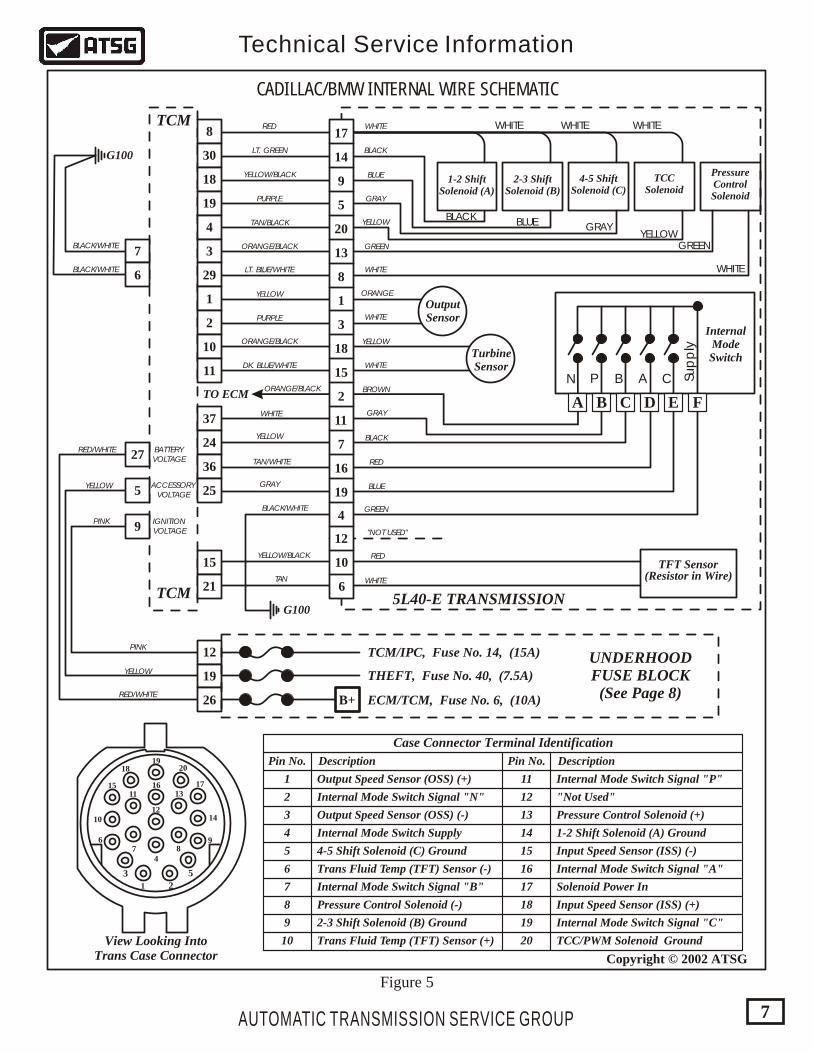
TFT Sensor
TO ECM
G100
G100
1-2 ShiftSolenoid (A)
2-3 ShiftSolenoid (B)
4-5 ShiftSolenoid (C)
TCCSolenoid
PressureControlSolenoid
WHITERED
WHITELT. BLUE/WHITE
DK. BLUE/WHITE
YELLOW
YELLOW
WHITE
WHITE
WHITE
WHITE
WHITE
TAN/WHITE
TAN
WHITE WHITE WHITE
BLACKLT. GREEN
BLACK
BLUE
BLUE
GRAYPURPLE
PURPLE
GRAYYELLOW
YELLOW/BLACK
TAN/BLACK
ORANGE/BLACK
ORANGE/BLACK
ORANGE/BLACK
YELLOW/BLACK
BLACK/WHITE
BLACK/WHITE
BLACK/WHITE
YELLOW
YELLOWGREEN GREEN
BROWN
GRAY
GRAY
BLACK
RED
RED/WHITE
RED/WHITE BATTERYVOLTAGE
ACCESSORYVOLTAGE
IGNITIONVOLTAGE
YELLOW
YELLOW
PINK
PINK
BLUE
GREEN
"NOT USED"
RED
ORANGE
(Resistor in Wire)
InternalModeSwitch
A B C D E F
C Sup
ply
ABPN
5L40-E TRANSMISSION
CADILLAC/BMW INTERNAL WIRE SCHEMATIC
Figure 5
2
3 5
48
9
10
11
12
13
20
1715 16
1819
14
76
1
View Looking IntoTrans Case Connector
Pin No. Pin No.
11
12
13
14
15
16
17
18
19
20
1
2
3
4
5
6
7
8
9
10
Description Description
Output Speed Sensor (OSS) (+)
Input Speed Sensor (ISS) (-)
Input Speed Sensor (ISS) (+)
Output Speed Sensor (OSS) (-)
Internal Mode Switch Signal "N"
Internal Mode Switch Signal "B"
Internal Mode Switch Signal "P"
Internal Mode Switch Signal "A"
Internal Mode Switch Signal "C"
Solenoid Power In
"Not Used"
Internal Mode Switch Supply
4-5 Shift Solenoid (C) Ground
1-2 Shift Solenoid (A) Ground
TCC/PWM Solenoid Ground
2-3 Shift Solenoid (B) Ground
Pressure Control Solenoid (-)
Pressure Control Solenoid (+)
Trans Fluid Temp (TFT) Sensor (-)
Trans Fluid Temp (TFT) Sensor (+)
Case Connector Terminal Identification
Copyright © 2002 ATSG
OutputSensor
TurbineSensor
17
14
9
5
20
8
10
6
1
3
18
11
7
16
19
15
2
4
12
13
TCM
ECM/TCM, Fuse No. 6, (10A)
THEFT, Fuse No. 40, (7.5A)
TCM/IPC, Fuse No. 14, (15A) UNDERHOODFUSE BLOCK
(See Page 8)
TCM8
30
18
19
4
3
29
1
2
10
11
37
24
36
25
15
21
27
7
6
5
9
12
19
26 B+
AUTOMATIC TRANSMISSION SERVICE GROUP
Technical Service Information
8
Copyright © 2002 ATSG
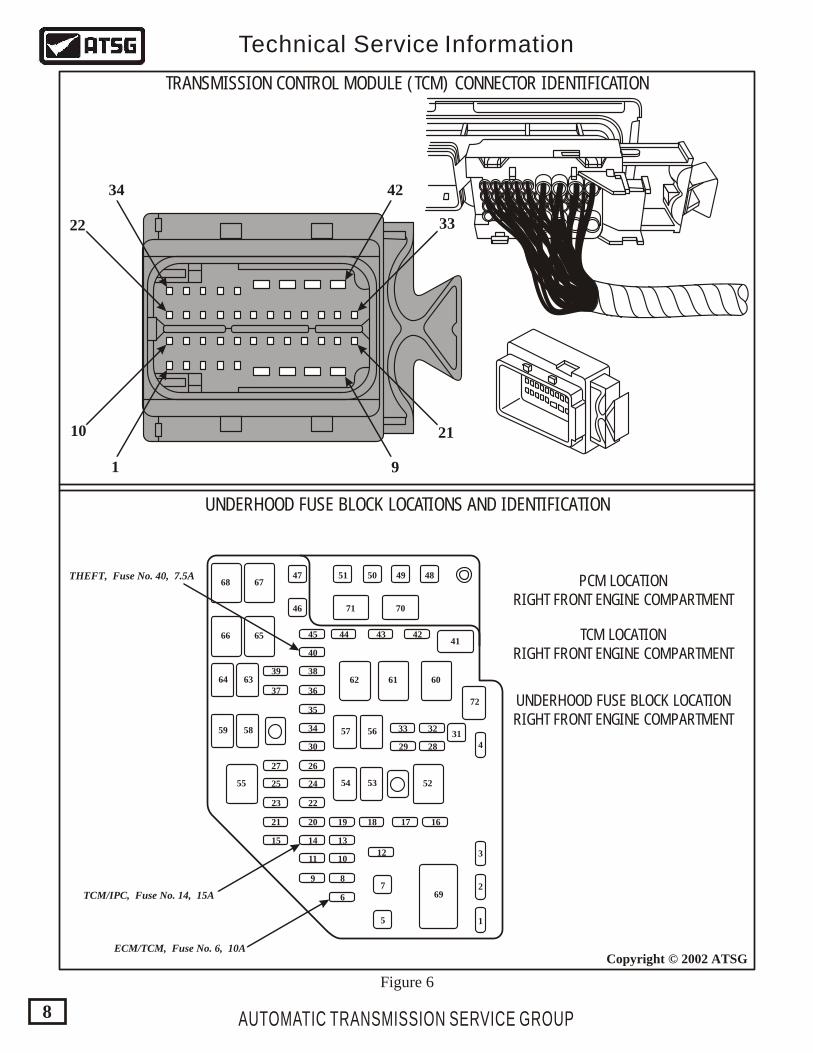
34
22 33
2110
1
42
9
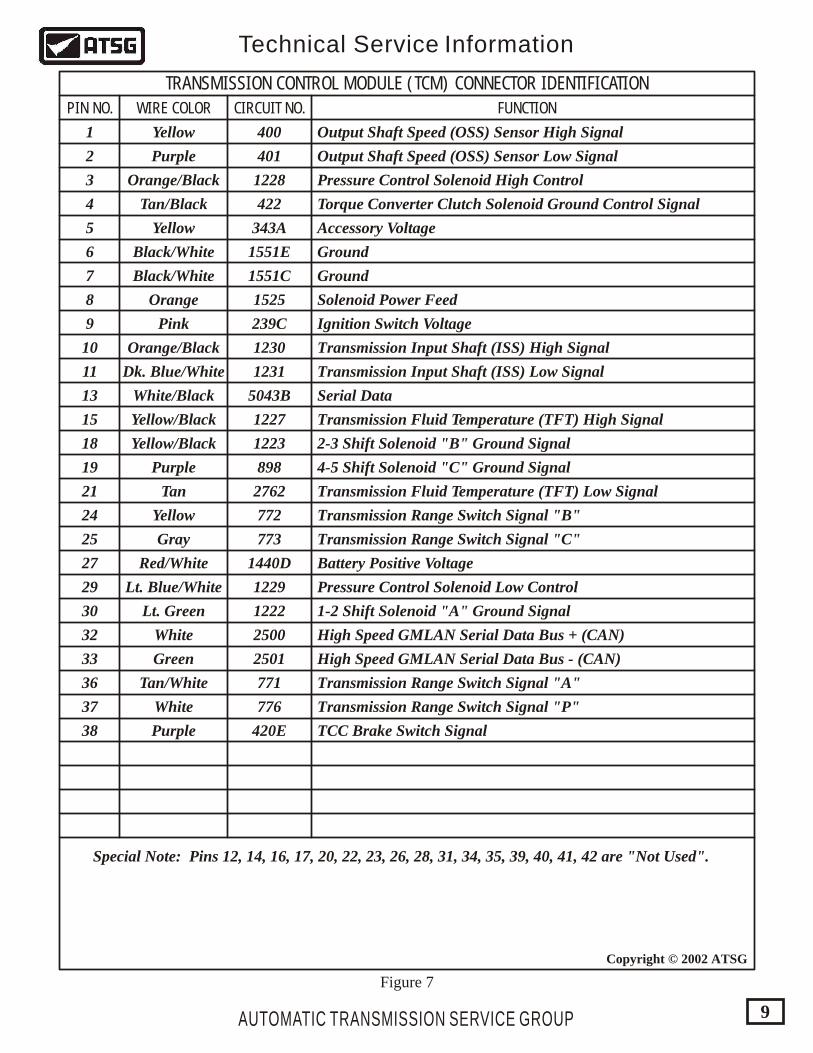
TRANSMISSION CONTROL MODULE (TCM) CONNECTOR IDENTIFICATION
UNDERHOOD FUSE BLOCK LOCATIONS AND IDENTIFICATION
PCM LOCATIONRIGHT FRONT ENGINE COMPARTMENT
TCM LOCATIONRIGHT FRONT ENGINE COMPARTMENT
UNDERHOOD FUSE BLOCK LOCATIONRIGHT FRONT ENGINE COMPARTMENT
5
7
31
46
4767
65
63
58 57
54
56
53
72
59
64 62 61 60
5255
68
66
48495051
71 70
41
3
4
2
12
6
8
10
13
19 18 17 16
9
11
14
20
22
24
26
36
38
40
45 44 43 42
35
34
30 29 28
3233
15
21
23
25
27
37
39
69
1
Figure 6
THEFT, Fuse No. 40, 7.5A
TCM/IPC, Fuse No. 14, 15A
ECM/TCM, Fuse No. 6, 10A
AUTOMATIC TRANSMISSION SERVICE GROUP
Technical Service Information
9
Copyright © 2002 ATSG
TRANSMISSION CONTROL MODULE (TCM) CONNECTOR IDENTIFICATION
PIN NO. WIRE COLOR CIRCUIT NO. FUNCTION
1
2
3
4
5
6
7
8
9
10
11
13
Special Note: Pins 12, 14, 16, 17, 20, 22, 23, 26, 28, 31, 34, 35, 39, 40, 41, 42 are "Not Used".
15
18
19
21
24
25
27
29
30
32
33
36
37
38
400
239C
401
422
343A
1551E
1551C
1525
1230
1231
1227
1223
1229
1222
2500
2501
898
2762
772
771
776
420E
773
1440D
5043B
1228Orange/Black
Orange/Black
White/Black
Yellow/Black
Yellow/Black
Orange
Pink
Tan/Black
Black/White
Black/White
Dk. Blue/White
Lt. Blue/White
Lt. Green
Green
Red/White
White
White
Tan/White
Yellow
Yellow
Yellow
Gray
Purple
Purple
Purple
Tan
Output Shaft Speed (OSS) Sensor High Signal
Pressure Control Solenoid High Control
Pressure Control Solenoid Low Control
Torque Converter Clutch Solenoid Ground Control Signal
Accessory Voltage
Solenoid Power Feed
Ignition Switch Voltage
Transmission Input Shaft (ISS) High Signal
Transmission Fluid Temperature (TFT) High Signal
Transmission Fluid Temperature (TFT) Low Signal
Transmission Range Switch Signal "B"
Transmission Range Switch Signal "C"
Transmission Range Switch Signal "A"
Transmission Range Switch Signal "P"
TCC Brake Switch Signal
Battery Positive Voltage
2-3 Shift Solenoid "B" Ground Signal
1-2 Shift Solenoid "A" Ground Signal
High Speed GMLAN Serial Data Bus + (CAN)
High Speed GMLAN Serial Data Bus - (CAN)
4-5 Shift Solenoid "C" Ground Signal
Transmission Input Shaft (ISS) Low Signal
Serial Data
Ground
Ground
Output Shaft Speed (OSS) Sensor Low Signal
Figure 7
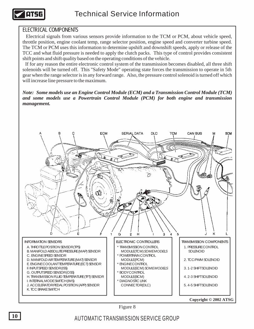
Figure 8
A. THROTTLE POSITION SENSOR (TPS) B. MANIFOLD ABSOLUTE PRESSURE (MAP) SENSOR C. ENGINE SPEED SENSOR D. MANIFOLD AIR TEMPERATURE (MAT) SENSOR E. ENGINE COOLANT TEMPERATURE (ECT) SENSOR F. INPUT SPEED SENSOR (ISS) G. OUTPUT SPEED SENSOR (OSS) H. TRANSMISSION FLUID TEMPERATURE (TFT) SENSOR I. INTERNAL MODE SWITCH (IMS) J. ACCELERATOR PEDAL POSITION (APP) SENSOR K. TCC BRAKE SWITCH
1. PRESSURE CONTROL SOLENOID
2. TCC/PWM SOLENOID
3. 1-2 SHIFT SOLENOID
4. 2-3 SHIFT SOLENOID
5. 4-5 SHIFT SOLENOID
* TRANSMISSION CONTROL MODULE (TCM) SOME MODELS * POWERTRAIN CONTROL MODULE (PCM) * ENGINE CONTROL MODULE (ECM) SOME MODELS * BODY CONTROL MODULE (BCM) * DIAGNOSTIC LINK CONNECTOR (DLC)
TRANSMISSION COMPONENTSTRANSMISSION COMPONENTSELECTRONIC CONTROLLERSELECTRONIC CONTROLLERSINFORMATION SENSORSINFORMATION SENSORS
ELECTRICAL COMPONENTS Electrical signals from various sensors provide information to the TCM or PCM, about vehicle speed, throttle position, engine coolant temp, range selector position, engine speed and converter turbine speed. The TCM or PCM uses this information to determine upshift and downshift speeds, apply or release of the TCC and what fluid pressure is needed to apply the clutch packs. This type of control provides consistent shift points and shift quality based on the operating conditions of the vehicle. If for any reason the entire electronic control system of the transmission becomes disabled, all three shift solenoids will be turned off. This "Safety Mode" operating state forces the transmission to operate in 5th gear when the range selector is in any forward range. Also, the pressure control solenoid is turned off which will increase line pressure to the maximum.
Note: Some models use an Engine Control Module (ECM) and a Transmission Control Module (TCM) and some models use a Powertrain Control Module (PCM) for both engine and transmission management.
AUTOMATIC TRANSMISSION SERVICE GROUP
Technical Service Information
10
Copyright © 2002 ATSG
CABPN
+
CIRCUIT
C P P/NA
1
1
1
1
1 1
1
1 1
1
1
1
1
1
1
1
1
0
0
0 0 0 0
0
0 0
0
0
00
0
0
0
0 0
B
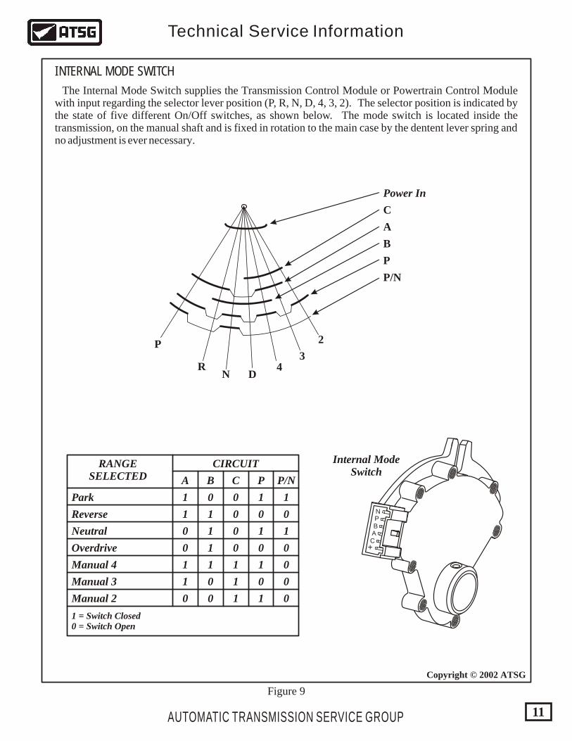
RANGESELECTED
Park
Reverse
Overdrive
Manual 4
Manual 3
Manual 2
1 = Switch Closed0 = Switch Open
Neutral
Internal ModeSwitch
Figure 9
P
RN D
43
2
C
A
B
P
P/N
Power In
INTERNAL MODE SWITCH
The Internal Mode Switch supplies the Transmission Control Module or Powertrain Control Module with input regarding the selector lever position (P, R, N, D, 4, 3, 2). The selector position is indicated by the state of five different On/Off switches, as shown below. The mode switch is located inside the transmission, on the manual shaft and is fixed in rotation to the main case by the dentent lever spring and no adjustment is ever necessary.
AUTOMATIC TRANSMISSION SERVICE GROUP
Technical Service Information
11
Copyright © 2002 ATSG
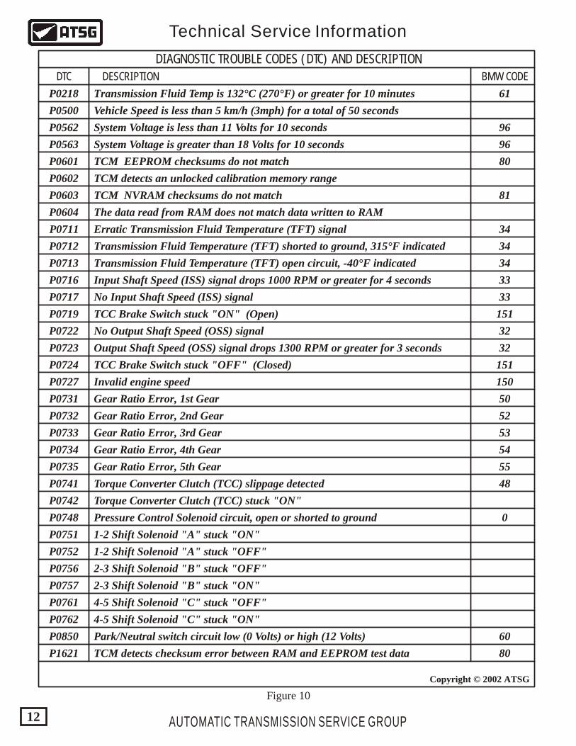
DTC BMW CODEDESCRIPTION
Figure 10
AUTOMATIC TRANSMISSION SERVICE GROUP
Technical Service Information
12
Copyright © 2002 ATSG
P0218 61
96
96
81
34
34
34
33
33
151
151
32
32
150
50
52
53
54
55
48
0
60
80
80
P0500
P0562
P0563
P0601
P0602
P0603
P0604
P0711
P0712
P0713
P0716
P0717
P0719
P0722
P0723
P0724
P0727
P0731
P0732
P0733
P0734
P0735
P0741
P0742
P0748
P0751
P0752
P0756
P0757
P0761
P0762
P0850
P1621
Transmission Fluid Temp is 132°C (270°F) or greater for 10 minutes
Vehicle Speed is less than 5 km/h (3mph) for a total of 50 seconds
System Voltage is less than 11 Volts for 10 seconds
System Voltage is greater than 18 Volts for 10 seconds
TCM EEPROM checksums do not match
TCM NVRAM checksums do not match
The data read from RAM does not match data written to RAM
Erratic Transmission Fluid Temperature (TFT) signal
Transmission Fluid Temperature (TFT) shorted to ground, 315°F indicated
Transmission Fluid Temperature (TFT) open circuit, -40°F indicated
Input Shaft Speed (ISS) signal drops 1000 RPM or greater for 4 seconds
Output Shaft Speed (OSS) signal drops 1300 RPM or greater for 3 seconds
No Input Shaft Speed (ISS) signal
No Output Shaft Speed (OSS) signal
TCC Brake Switch stuck "ON" (Open)
TCC Brake Switch stuck "OFF" (Closed)
Invalid engine speed
Gear Ratio Error, 1st Gear
Gear Ratio Error, 2nd Gear
Gear Ratio Error, 3rd Gear
Gear Ratio Error, 4th Gear
Gear Ratio Error, 5th Gear
Torque Converter Clutch (TCC) slippage detected
Torque Converter Clutch (TCC) stuck "ON"
Pressure Control Solenoid circuit, open or shorted to ground
1-2 Shift Solenoid "A" stuck "ON"
1-2 Shift Solenoid "A" stuck "OFF"
2-3 Shift Solenoid "B" stuck "OFF"
4-5 Shift Solenoid "C" stuck "OFF"
4-5 Shift Solenoid "C" stuck "ON"
Park/Neutral switch circuit low (0 Volts) or high (12 Volts)
TCM detects checksum error between RAM and EEPROM test data
2-3 Shift Solenoid "B" stuck "ON"
TCM detects an unlocked calibration memory range
DIAGNOSTIC TROUBLE CODES (DTC) AND DESCRIPTION
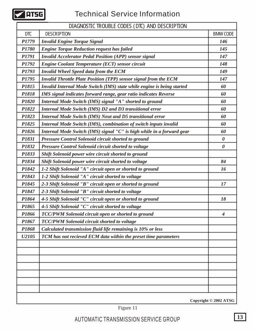
DIAGNOSTIC TROUBLE CODES (DTC) AND DESCRIPTION
DTC BMW CODEDESCRIPTION
P1779
P1780
P1791
P1792
P1793
P1795
P1815 60
60
60
60
60
60
60
0
0
149
148
147
147
145
146
84
16
17
18
4
P1818
P1820
P1822
P1823
P1825
P1826
P1831
P1832
P1833
P1834
P1842
P1843
P1845
P1847
P1864
P1865
P1866
P1867
P1868
U2105
Invalid Engine Torque Signal
Invalid Accelerator Pedal Position (APP) sensor signal
Invalid Throttle Plate Position (TPP) sensor signal from the ECM
Invalid Internal Mode Switch (IMS) state while engine is being started
IMS signal indicates forward range, gear ratio indicates Reverse
Internal Mode Switch (IMS) signal "A" shorted to ground
Internal Mode Switch (IMS) signal "C" is high while in a forward gear
Pressure Control Solenoid circuit shorted to ground
Pressure Control Solenoid circuit shorted to voltage
Shift Solenoid power wire circuit shorted to ground
Shift Solenoid power wire circuit shorted to voltage
1-2 Shift Solenoid "A" circuit open or shorted to ground
2-3 Shift Solenoid "B" circuit open or shorted to ground
4-5 Shift Solenoid "C" circuit open or shorted to ground
TCC/PWM Solenoid circuit open or shorted to ground
TCC/PWM Solenoid circuit shorted to voltage
Calculated transmission fluid life remaining is 10% or less
TCM has not recieved ECM data within the preset time parameters
4-5 Shift Solenoid "C" circuit shorted to voltage
2-3 Shift Solenoid "B" circuit shorted to voltage
1-2 Shift Solenoid "A" circuit shorted to voltage
Internal Mode Switch (IMS) D2 and D3 transitional error
Internal Mode Switch (IMS) Neut and D5 transitional error
Internal Mode Switch (IMS), combination of switch inputs invalid
Invalid Wheel Speed data from the ECM
Engine Coolant Temperature (ECT) sensor circuit
Engine Torque Reduction request has failed
Figure 11
AUTOMATIC TRANSMISSION SERVICE GROUP
Technical Service Information
13
Copyright © 2002 ATSG
- Manual Third can be used for conditions where it is desirable to use only 3 gear ratios, such as trailer towing or hilly terrain. This range also helps for engine braking when descending grades. Upshifts and downshifts all occur automatically, except 4th and 5th is prohibited. Manual 3rd can be selected at any vehicle speed but will downshift to 3rd only if vehicle speed is low enough not to over-rev the engine. Manual downshifts are controlled by the TCM, not the manual valve.
The 5L40-E transmission is a completely new design rear wheel drive unit and was designed to be a four or five speed transmission. The same case and components are used for both applications with the exclusion of the 2nd clutch, 2nd coast clutch and the 2nd sprag clutch, and the use of a smaller ravigneaux planetary carrier assembly in the 4 speed version. The Hydra-matic 5L40-E is a fully automatic, five forward speed, rear wheel drive, fully electronic controlled transmission, with a maximum torque rating of 360 Nm. It consists primarily of a four element (Lock-Up) torque converter, one ravigneaux planetary gear set, nine multiple-disc friction clutch packs, four mechanical sprag clutches and a hydraulic pressurization and control system. We have provided you with an illustration to identify the location of the nine different clutch packs, the four mechanical sprag clutches and a component application chart in Figures 2 and 3. The ravigneaux planetary gear set provides the five forward speeds and reverse. Changing gear ratios is fully automatic and is accomplished through the use of a Transmission Control Module (TCM). The TCM recieves and monitors various electronic sensor inputs and uses this information to shift the transmission at the optimum time, as illustrated in Figure 8. The TCM commands three on/off Shift Solenoids to control shift timing. The TCM controls shift feel through the Pressure Control Solenoid. The TCM also controls the apply and release of the torque converter clutch through a TCC/PWM Solenoid. Refer to Figure 4 for the solenoid application chart for each gear, along with case connector pin identification and a resistance chart for the internal components. Refer to Figure 5 for the internal wiring schematic. Notice also in Figure 5 that this transmission uses an Internal Mode Switch (IMS). The IMS operation is illustrated and explained in Figure 9, and description of each gear range is explained in this section. The hydraulic system primarily consists of a 13 vane pump, two control valve bodies, two channel plates, converter housing and transmission case. The pump maintains the working pressures needed to stroke the clutch pistons that apply or release the friction components.
AUTOMATIC TRANSMISSION SERVICE GROUP
Technical Service Information
14
GENERAL OPERATION AND DESCRIPTION
- Manual Fourth can be used for conditions where it may be desirable to use only 4 gear ratios, such as trailer towing or hilly terrain. This range is also helpful for engine braking when descending slight grades. Upshifts and downshifts all occur automatically, except 5th gear is prohibited. Manual Fourth can be selected at any vehicle speed but will downshift into 4th gear only if vehicle speed is low enough not to over-rev the engine. Manual downshifts are controlled by the TCM, not the manual valve location.
- Overdrive range should be used for all normal driving conditions for maximum efficiency and fuel economy. Overdrive range allows the transmission to upshift automatically into each of the 5 forward gear ratios. Downshifts to a lower gear are possible for safe passing by depressing the accelerator, or by manually selecting a lower gear with the shift selector.
- Reverse position enables the vehicle to be operated in a rearward direction.
- Park position enables the engine to be started while preventing the vehicle from rolling either forward or backward. Park position should not be selected until the vehicle has come to a complete stop. For safety reasons, the vehicles parking brake should always be used in addition to the "Park" position.
- Neutral position enables the engine to start and operate without driving the vehicle. If necessary, this position should be selected to restart the engine while the vehicle is moving.
P
R
N
4
3
D
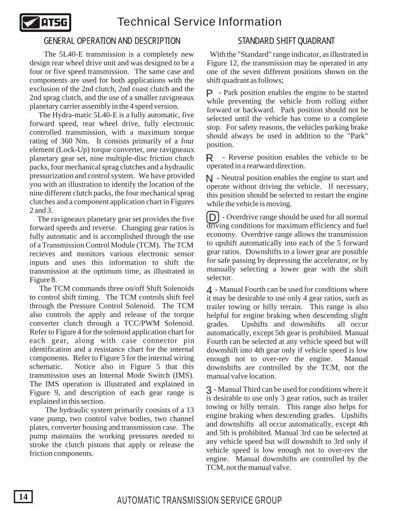
With the "Standard" range indicator, as illustrated in Figure 12, the transmission may be operated in any one of the seven different positions shown on the shift quadrant as follows;
STANDARD SHIFT QUADRANT
AUTOMATIC TRANSMISSION SERVICE GROUP
Technical Service Information
15
Copyright © 2002 ATSG
Copyright © 2002 ATSG
D 4 3 2NRP
"STANDARD"RANGE INDICATOR
Figure 12
GMHYDRAMATIC
STRASBOURG
FRANCEHYDRAMATIC
STRASBOURG
FRANCE
*0139781RVO*
*0139781RVO*
96 02296 022 832
18/12/99 019971
18:54
1423875
P08
0139978196022832
VO
GMGM
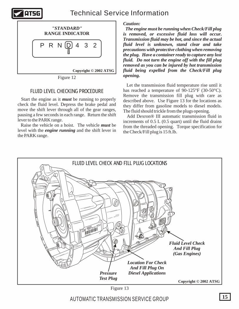
Figure 13
Fluid Level CheckAnd Fill Plug(Gas Engines)
Location For CheckAnd Fill Plug On
Diesel ApplicationsPressureTest Plug
FLUID LEVEL CHECK AND FILL PLUG LOCATIONS
FLUID LEVEL CHECKING PROCEDURE
Start the engine as it must be running to properly check the fluid level. Depress the brake pedal and move the shift lever through all of the gear ranges, pausing a few seconds in each range. Return the shift lever to the PARK range. Raise the vehicle on a hoist. The vehicle must be level with the engine running and the shift lever in the PARK range.
Caution: The engine must be running when Check/Fill plug is removed, or excessive fluid loss will occur. Transmission fluid may be hot, and since the actual fluid level is unknown, stand clear and take precautions with protective clothing when removing the plug. Have a container ready to capture any lost fluid. Do not turn the engine off with the fill plug removed as you can be injured by hot transmission fluid being expelled from the Check/Fill plug opening.
Let the transmission fluid temperature rise until it has reached a temperature of 90-125°F (30-50°C). Remove the transmission fill plug with care as described above. Use Figure 13 for the locations as they differ from gasoline models to diesel models. The fluid should trickle from the plugs opening. Add Dexron® III automatic transmission fluid in increments of 0.5 L (0.5 quart) until the fluid drains from the threaded opening. Torque specification for the Check/Fill plug is 15 ft.lb.
GMHYDRAMATIC
STRASBOURG
FRANCEHYDRAMATIC
STRASBOURG
FRANCE
*0139781RVO*
*0139781RVO*
96 02296 022 832
18/12/99 019971
18:54
1423875
P08
0139978196022832
VO
GMGM
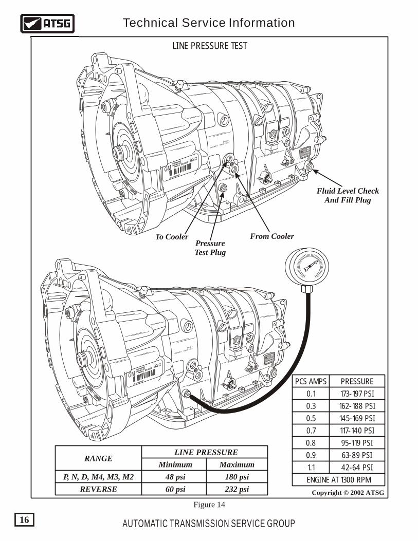
Figure 14
Fluid Level CheckAnd Fill Plug
To Cooler From CoolerPressureTest Plug
RANGELINE PRESSURE
Minimum Maximum
P, N, D, M4, M3, M2 48 psi
60 psi
180 psi
232 psiREVERSE
GMHYDRAMATIC
STRASBOURG
FRANCEHYDRAMATIC
STRASBOURG
FRANCE
*0139781RVO*
*0139781RVO*
96 02296 022 832
18/12/99 019971
18:54
1423875
P08
0139978196022832
VO
GMGM
lllll ll ll ll ll ll ll ll ll ll ll ll ll ll ll ll ll ll llll llll ll
AUTOMATIC TRANSMISSION SERVICE GROUP
Technical Service Information
16
Copyright © 2002 ATSG
LINE PRESSURE TEST
PCS AMPS
0.1
0.3
0.5
0.7
0.8
0.9
1.1
PRESSURE
173-197 PSI
162-188 PSI
145-169 PSI
117-140 PSI
95-119 PSI
63-89 PSI
42-64 PSI
ENGINE AT 1300 RPM
51
52
52
52
52
52
52
8
37
48
7
1232
21
51
50
50
53 52
2
2
2
12
2
2
48
3
48
48
16
48
48
53
5
6
4
4
247
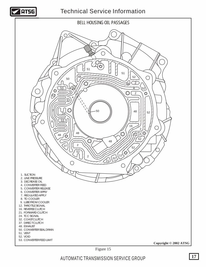
1. SUCTION 2. LINE PRESSURE 3. DECREASE OIL 4. CONVERTER FEED 5. CONVERTER RELEASE 6. CONVERTER APPLY 7. REGULATED APPLY 8. TO COOLER 9. LUBE FROM COOLER 12. THROTTLE SIGNAL 16. REVERSE CLUTCH 21. FORWARD CLUTCH 24. TCC SIGNAL 32. COAST CLUTCH 37. DIRECT CLUTCH 48. EXHAUST 50. CONVERTER SEAL DRAIN 51. VENT 52. VOID 53. CONVERTER FEED LIMIT
BELL HOUSING OIL PASSAGES
AUTOMATIC TRANSMISSION SERVICE GROUP
Technical Service Information
17
Copyright © 2002 ATSG
Figure 15
51
48
7
51
50
5352
2
2
2
12
2
2
48
48
3
3
3
48
48
48
16
48
48
53
5
6
4
4
7
52
6
52
1232
21
3724
16
8
24
2
1
7
8
48
52
(233)3
1232
32
32
(203)
(203)
52
52
21
37
37(203)
(203)
24
16
16
52
522
52
GM
9
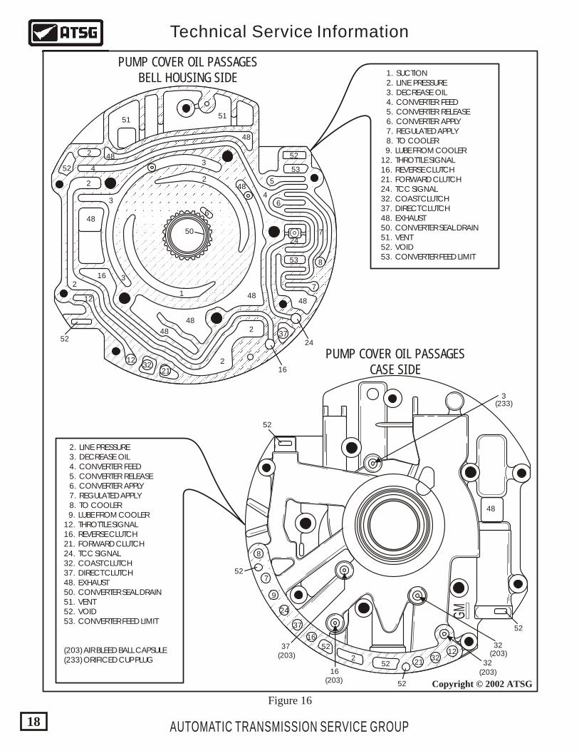
PUMP COVER OIL PASSAGESBELL HOUSING SIDE
PUMP COVER OIL PASSAGESCASE SIDE
1. SUCTION 2. LINE PRESSURE 3. DECREASE OIL 4. CONVERTER FEED 5. CONVERTER RELEASE 6. CONVERTER APPLY 7. REGULATED APPLY 8. TO COOLER 9. LUBE FROM COOLER 12. THROTTLE SIGNAL 16. REVERSE CLUTCH 21. FORWARD CLUTCH 24. TCC SIGNAL 32. COAST CLUTCH 37. DIRECT CLUTCH 48. EXHAUST 50. CONVERTER SEAL DRAIN 51. VENT 52. VOID 53. CONVERTER FEED LIMIT
2. LINE PRESSURE 3. DECREASE OIL 4. CONVERTER FEED 5. CONVERTER RELEASE 6. CONVERTER APPLY 7. REGULATED APPLY 8. TO COOLER 9. LUBE FROM COOLER 12. THROTTLE SIGNAL 16. REVERSE CLUTCH 21. FORWARD CLUTCH 24. TCC SIGNAL 32. COAST CLUTCH 37. DIRECT CLUTCH 48. EXHAUST 50. CONVERTER SEAL DRAIN 51. VENT 52. VOID 53. CONVERTER FEED LIMIT
(203) AIR BLEED BALL CAPSULE (233) ORIFICED CUP PLUG
AUTOMATIC TRANSMISSION SERVICE GROUP
Technical Service Information
18
Copyright © 2002 ATSG
Figure 16
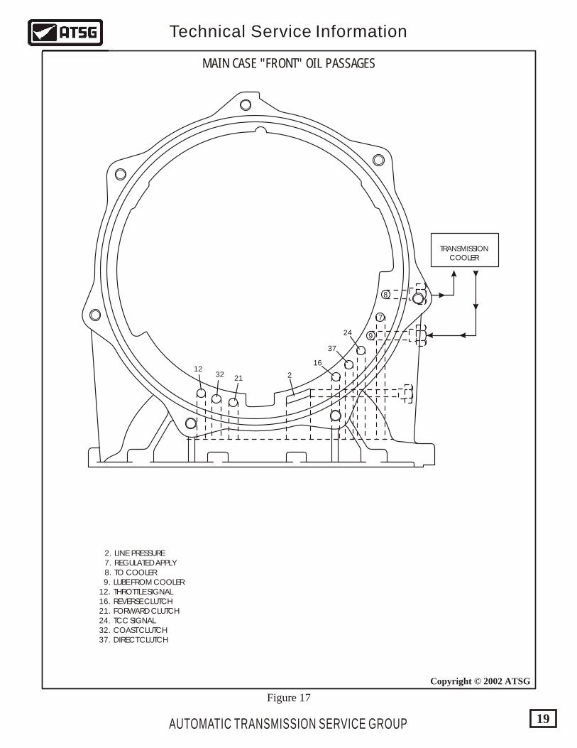
MAIN CASE "FRONT" OIL PASSAGES
2. LINE PRESSURE 7. REGULATED APPLY 8. TO COOLER 9. LUBE FROM COOLER 12. THROTTLE SIGNAL 16. REVERSE CLUTCH 21. FORWARD CLUTCH 24. TCC SIGNAL 32. COAST CLUTCH 37. DIRECT CLUTCH
7
924
TRANSMISSIONCOOLER
37
16
2213212
8
AUTOMATIC TRANSMISSION SERVICE GROUP
Technical Service Information
19
Copyright © 2002 ATSG
Figure 17
1232 21
2
37
24 7
16
15183430
35
41
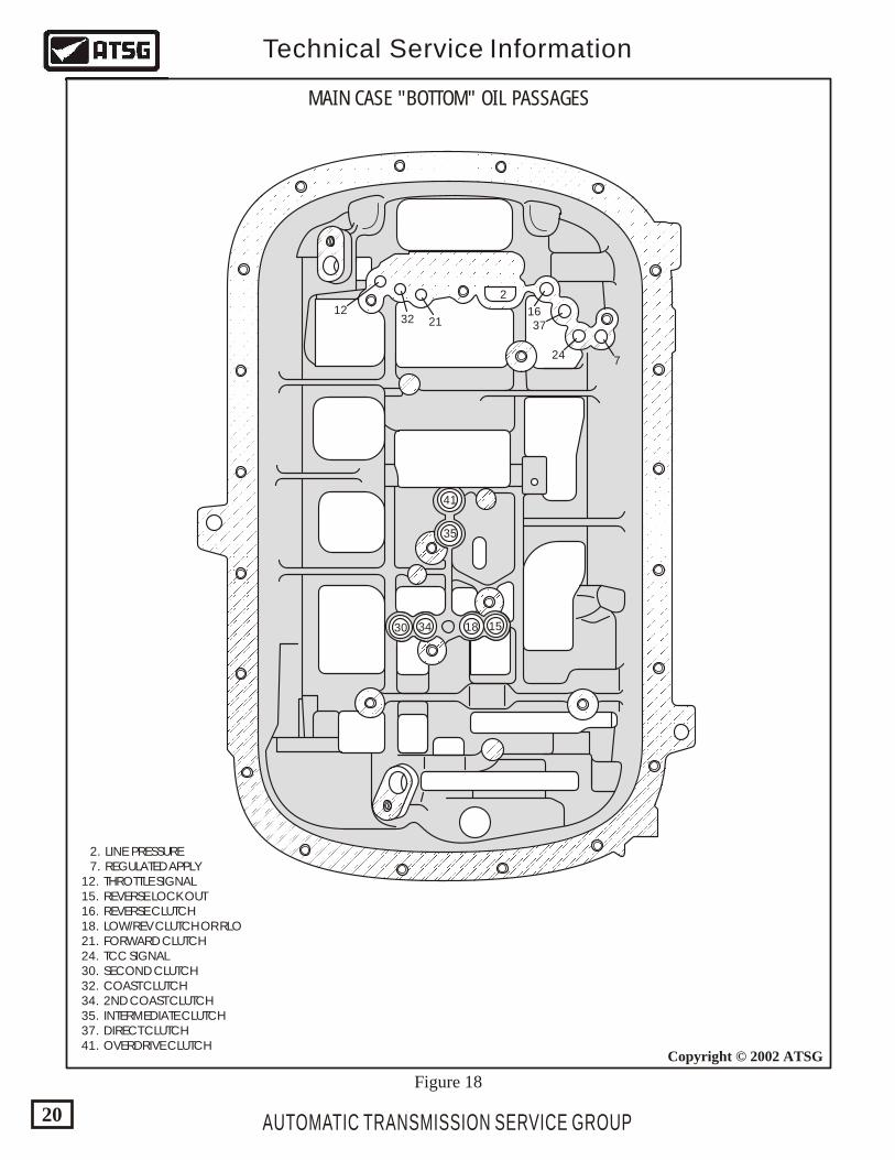
MAIN CASE "BOTTOM" OIL PASSAGES
2. LINE PRESSURE 7. REGULATED APPLY 12. THROTTLE SIGNAL 15. REVERSE LOCK OUT 16. REVERSE CLUTCH 18. LOW/REV CLUTCH OR RLO 21. FORWARD CLUTCH 24. TCC SIGNAL 30. SECOND CLUTCH 32. COAST CLUTCH 34. 2ND COAST CLUTCH 35. INTERMEDIATE CLUTCH 37. DIRECT CLUTCH 41. OVERDRIVE CLUTCH
AUTOMATIC TRANSMISSION SERVICE GROUP
Technical Service Information
20
Copyright © 2002 ATSG
Figure 18
4848
4852
5252
52
3535
30
33
25
25
25
25
17
44
10
10
10
28
27
2
30
40
32
38
20
20
20
22
30
52
30
22
14
15
25
26
14
19
19
54
44
28
44
48
48
4844
48
48
3433
33
39
35
3536
22
17
43
52
22
52
24
19
26
38
31
13
19
42
21
15
2
2
2
"FRONT" VALVE BODY OIL PASSAGES
"REAR" VALVE BODY OIL PASSAGES
4848
16
48
23
1548
52 48
37
3711
1252
52 52
54
10
7
7
2
2
10
24
36
52
3639
4252
5443
48
23
38
48
40 40 40
28
47
47
10
2
46
13
27
13
20
37
36
52
48
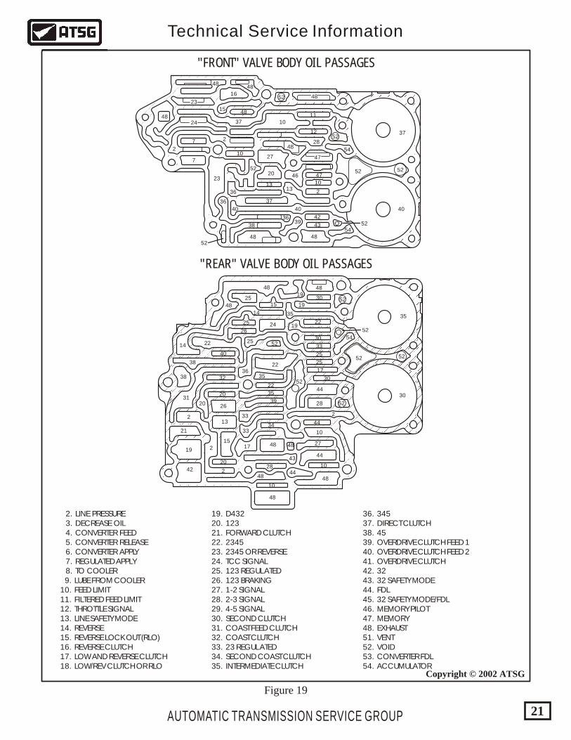
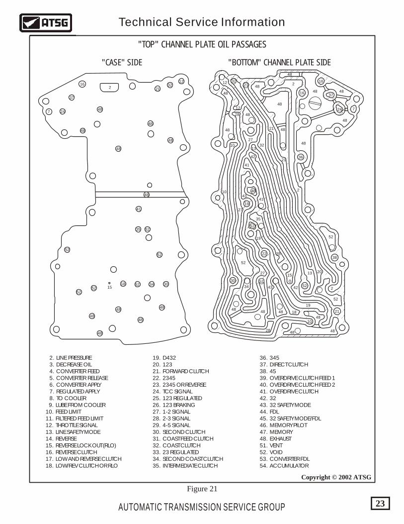
2. LINE PRESSURE 3. DECREASE OIL 4. CONVERTER FEED 5. CONVERTER RELEASE 6. CONVERTER APPLY 7. REGULATED APPLY 8. TO COOLER 9. LUBE FROM COOLER 10. FEED LIMIT 11. FILTERED FEED LIMIT 12. THROTTLE SIGNAL 13. LINE SAFETY MODE 14. REVERSE 15. REVERSE LOCK OUT (RLO) 16. REVERSE CLUTCH 17. LOW AND REVERSE CLUTCH 18. LOW/REV CLUTCH OR RLO
19. D432 20. 123 21. FORWARD CLUTCH 22. 2345 23. 2345 OR REVERSE 24. TCC SIGNAL 25. 123 REGULATED 26. 123 BRAKING 27. 1-2 SIGNAL 28. 2-3 SIGNAL 29. 4-5 SIGNAL 30. SECOND CLUTCH 31. COAST FEED CLUTCH 32. COAST CLUTCH 33. 23 REGULATED 34. SECOND COAST CLUTCH 35. INTERMEDIATE CLUTCH
36. 345 37. DIRECT CLUTCH 38. 45 39. OVERDRIVE CLUTCH FEED 1 40. OVERDRIVE CLUTCH FEED 2 41. OVERDRIVE CLUTCH 42. 32 43. 32 SAFETY MODE 44. FDL 45. 32 SAFETY MODE/FDL 46. MEMORY PILOT 47. MEMORY 48. EXHAUST 51. VENT 52. VOID 53. CONVERTER FDL 54. ACCUMULATOR
AUTOMATIC TRANSMISSION SERVICE GROUP
Technical Service Information
21
Copyright © 2002 ATSG
Figure 19
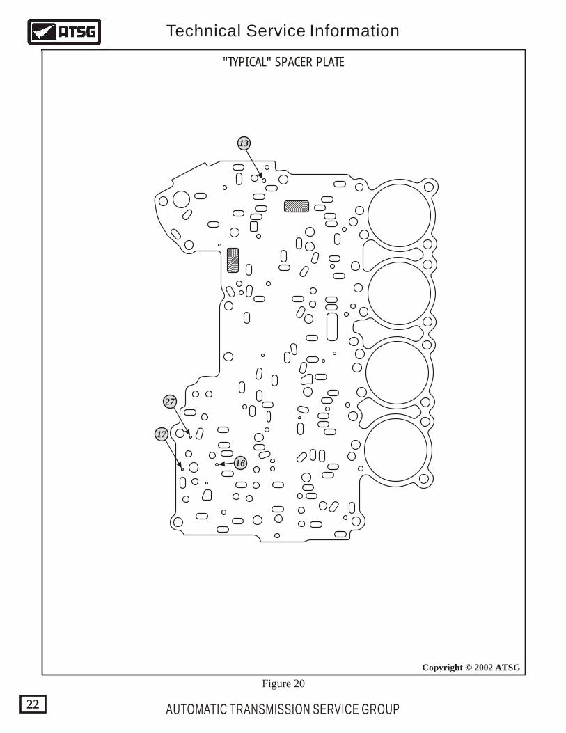
"TYPICAL" SPACER PLATE
13
27
17
16
AUTOMATIC TRANSMISSION SERVICE GROUP
Technical Service Information
22
Copyright © 2002 ATSG
Figure 20
24
37
7
48
48
48 48
48
16
19
52
22
52
30 52
16
36
38
21
52
2
2
2
48
48
48
3212
12
32
42
41
41
21
21
21
48
48
48
20
28
28
27
1013
13
10
10
27
27
42
48
43
43
4848
52
52
35
35
15
19
19
34
48 18
48
48
48
1232
21
37
24748
48
48
48
48
48
48
48
48
41
15
52
35 52
52
303418 5252
52
48
48
216
2. LINE PRESSURE 3. DECREASE OIL 4. CONVERTER FEED 5. CONVERTER RELEASE 6. CONVERTER APPLY 7. REGULATED APPLY 8. TO COOLER 9. LUBE FROM COOLER 10. FEED LIMIT 11. FILTERED FEED LIMIT 12. THROTTLE SIGNAL 13. LINE SAFETY MODE 14. REVERSE 15. REVERSE LOCK OUT (RLO) 16. REVERSE CLUTCH 17. LOW AND REVERSE CLUTCH 18. LOW/REV CLUTCH OR RLO
19. D432 20. 123 21. FORWARD CLUTCH 22. 2345 23. 2345 OR REVERSE 24. TCC SIGNAL 25. 123 REGULATED 26. 123 BRAKING 27. 1-2 SIGNAL 28. 2-3 SIGNAL 29. 4-5 SIGNAL 30. SECOND CLUTCH 31. COAST FEED CLUTCH 32. COAST CLUTCH 33. 23 REGULATED 34. SECOND COAST CLUTCH 35. INTERMEDIATE CLUTCH
36. 345 37. DIRECT CLUTCH 38. 45 39. OVERDRIVE CLUTCH FEED 1 40. OVERDRIVE CLUTCH FEED 2 41. OVERDRIVE CLUTCH 42. 32 43. 32 SAFETY MODE 44. FDL 45. 32 SAFETY MODE/FDL 46. MEMORY PILOT 47. MEMORY 48. EXHAUST 51. VENT 52. VOID 53. CONVERTER FDL 54. ACCUMULATOR
"TOP" CHANNEL PLATE OIL PASSAGES
"CASE" SIDE "BOTTOM" CHANNEL PLATE SIDE
AUTOMATIC TRANSMISSION SERVICE GROUP
Technical Service Information
23
Copyright © 2002 ATSG
Figure 21
AUTOMATIC TRANSMISSION SERVICE GROUP
Technical Service Information
24
Copyright © 2002 ATSG
Figure 22
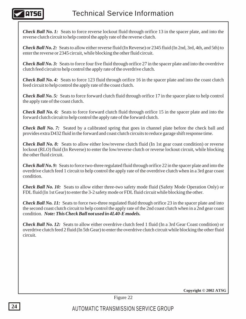
Check Ball No. 1: Seats to force reverse lockout fluid through orifice 13 in the spacer plate, and into the reverse clutch circuit to help control the apply rate of the reverse clutch.
Check Ball No. 2: Seats to allow either reverse fluid (In Reverse) or 2345 fluid (In 2nd, 3rd, 4th, and 5th) to enter the reverse or 2345 circuit, while blocking the other fluid circuit.
Check Ball No. 3: Seats to force four five fluid through orifice 27 in the spacer plate and into the overdrive clutch feed circuit to help control the apply rate of the overdrive clutch.
Check Ball No. 4: Seats to force 123 fluid through orifice 16 in the spacer plate and into the coast clutch feed circuit to help control the apply rate of the coast clutch.
Check Ball No. 5: Seats to force forward clutch fluid through orifice 17 in the spacer plate to help control the apply rate of the coast clutch.
Check Ball No. 6: Seats to force forward clutch fluid through orifice 15 in the spacer plate and into the forward clutch circuit to help control the apply rate of the forward clutch.
Check Ball No. 7: Seated by a calibrated spring that goes in channel plate before the check ball and provides extra D432 fluid in the forward and coast clutch circuits to reduce garage shift response time.
Check Ball No. 8: Seats to allow either low/reverse clutch fluid (In 1st gear coast condition) or reverse lockout (RLO) fluid (In Reverse) to enter the low/reverse clutch or reverse lockout circuit, while blocking the other fluid circuit.
Check Ball No. 9: Seats to force two-three regulated fluid through orifice 22 in the spacer plate and into the overdrive clutch feed 1 circuit to help control the apply rate of the overdrive clutch when in a 3rd gear coast condition.
Check Ball No. 10: Seats to allow either three-two safety mode fluid (Safety Mode Operation Only) or FDL fluid (In 1st Gear) to enter the 3-2 safety mode or FDL fluid circuit while blocking the other.
Check Ball No. 11: Seats to force two-three regulated fluid through orifice 23 in the spacer plate and into the second coast clutch circuit to help control the apply rate of the 2nd coast clutch when in a 2nd gear coast condition. Note: This Check Ball not used in 4L40-E models.
Check Ball No. 12: Seats to allow either overdrive clutch feed 1 fluid (In a 3rd Gear Coast condition) or overdrive clutch feed 2 fluid (In 5th Gear) to enter the overdrive clutch circuit while blocking the other fluid circuit.
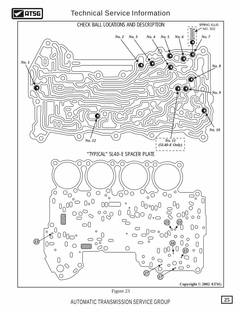
CHECK BALL LOCATIONS AND DESCRIPTION
"TYPICAL" 5L40-E SPACER PLATE
No. 2 No. 3 No. 4 No. 5 No. 6 No. 7
No. 8
No. 9
No. 10
No. 11(5L40-E Only)
No. 12
No. 1
13
2717
15
16
23 22
AUTOMATIC TRANSMISSION SERVICE GROUP
Technical Service Information
25
Copyright © 2002 ATSG
SPRING ILLUS.NO. 302
Figure 23
AUTOMATIC TRANSMISSION SERVICE GROUP
Technical Service Information
26
Copyright © 2002 ATSG
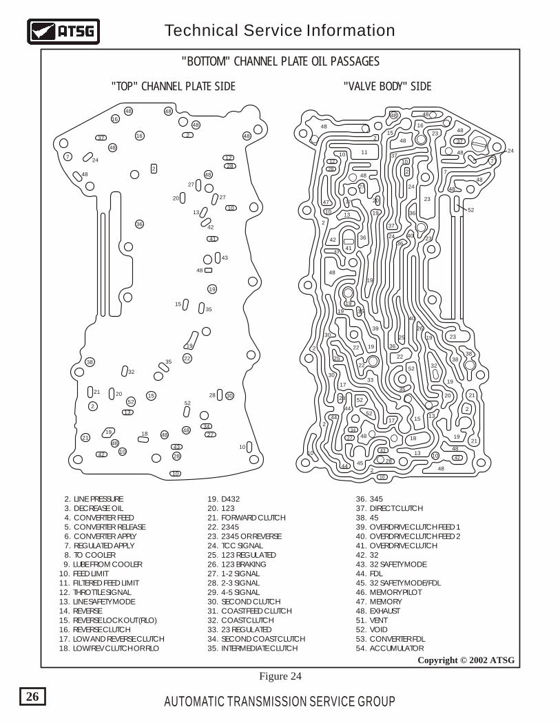
Figure 24
48
48
48
36
19
22
30
4848
4821
1028
1552
2
38
48
48
7
48
16
1637
24
27
2720
13
42
43
32
20 28
10
34
27
43
42
1819
10
13
52
21
35
48
1535
41
48
2
12
10
282
19
2. LINE PRESSURE 3. DECREASE OIL 4. CONVERTER FEED 5. CONVERTER RELEASE 6. CONVERTER APPLY 7. REGULATED APPLY 8. TO COOLER 9. LUBE FROM COOLER 10. FEED LIMIT 11. FILTERED FEED LIMIT 12. THROTTLE SIGNAL 13. LINE SAFETY MODE 14. REVERSE 15. REVERSE LOCK OUT (RLO) 16. REVERSE CLUTCH 17. LOW AND REVERSE CLUTCH 18. LOW/REV CLUTCH OR RLO
19. D432 20. 123 21. FORWARD CLUTCH 22. 2345 23. 2345 OR REVERSE 24. TCC SIGNAL 25. 123 REGULATED 26. 123 BRAKING 27. 1-2 SIGNAL 28. 2-3 SIGNAL 29. 4-5 SIGNAL 30. SECOND CLUTCH 31. COAST FEED CLUTCH 32. COAST CLUTCH 33. 23 REGULATED 34. SECOND COAST CLUTCH 35. INTERMEDIATE CLUTCH
36. 345 37. DIRECT CLUTCH 38. 45 39. OVERDRIVE CLUTCH FEED 1 40. OVERDRIVE CLUTCH FEED 2 41. OVERDRIVE CLUTCH 42. 32 43. 32 SAFETY MODE 44. FDL 45. 32 SAFETY MODE/FDL 46. MEMORY PILOT 47. MEMORY 48. EXHAUST 51. VENT 52. VOID 53. CONVERTER FDL 54. ACCUMULATOR
"BOTTOM" CHANNEL PLATE OIL PASSAGES
"VALVE BODY" SIDE"TOP" CHANNEL PLATE SIDE
2
2
2
2
10
2
48
48
48
1137
37
24
24 23
23
3832
26
25
36
30
30
39
35
36
22
22
25
28
33
22
52
52
44
48
28
48
48
18
13 10
13
4445
4452
34
43
10
42
27
15
17
17
19
20
19
19
19 35
19
1921
21
2
38
40
52
40
10
1012
28
27
2027
43
47
1013 19
19
42
41
36
48
48
48
48
48
23
23
36
2
48
48 24
7
7
37
16
15
Copyright © 2002 ATSG
1
3
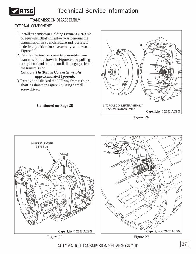
1 TORQUE CONVERTER ASSEMBLY 3 TRANSMISSION ASSEMBLY
AUTOMATIC TRANSMISSION SERVICE GROUP
Technical Service Information
27
Copyright © 2002 ATSG
Figure 25 Figure 27
Figure 26
TRANSMISSION DISASSEMBLY
EXTERNAL COMPONENTS
GMHYDRAMATIC
STRASBOURG
FRANCEHYDRAMATIC
STRASBOURG
FRANCE
*0139781RVO*
*0139781RVO*
96 02296 022 832
18/12/99 019971
18:54
1423875
P08
0139978196022832
VO
GMGM
TECKPAKFITZ-ALL
Copyright © 2002 ATSG
HOLDING FIXTUREJ-8763-02
1. Install transmission Holding Fixture J-8763-02 or equivalent that will allow you to mount the transmission in a bench fixture and rotate it to a desired position for disassembly, as shown in Figure 25. 2. Remove the torque converter assembly from transmission as shown in Figure 26, by pulling straight out and rotating until dis-engaged from the transmission. Caution: The Torque Converter weighs approximately 26 pounds. 3. Remove and discard the "O" ring from turbine shaft, as shown in Figure 27, using a small screwdriver.
Continued on Page 28
96023017GM
AUTOMATIC TRANSMISSION SERVICE GROUP
Technical Service Information
28
Copyright © 2002 ATSGCopyright © 2002 ATSG
Copyright © 2002 ATSG
GMHYDRAMATIC
STRASBOURG
FRANCEHYDRAMATIC
STRASBOURG
FRANCE
*0139781RVO*
*0139781RVO*
96 02296 022 832
18/12/99 019971
18:54
1423875
P08
0139978196022832
VO
GMGM
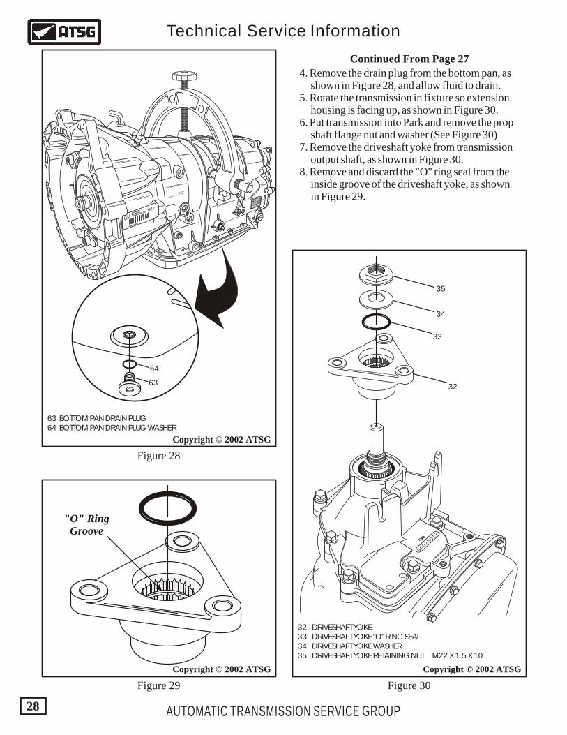
63
64
63 BOTTOM PAN DRAIN PLUG 64 BOTTOM PAN DRAIN PLUG WASHER
Figure 28
Figure 29 Figure 30
32
33
34
35
32. DRIVESHAFT YOKE 33. DRIVESHAFT YOKE "O" RING SEAL 34. DRIVESHAFT YOKE WASHER 35. DRIVESHAFT YOKE RETAINING NUT M22 X 1.5 X 10
"O" RingGroove
Continued From Page 27
4. Remove the drain plug from the bottom pan, as shown in Figure 28, and allow fluid to drain. 5. Rotate the transmission in fixture so extension housing is facing up, as shown in Figure 30. 6. Put transmission into Park and remove the prop shaft flange nut and washer (See Figure 30) 7. Remove the driveshaft yoke from transmission output shaft, as shown in Figure 30. 8. Remove and discard the "O" ring seal from the inside groove of the driveshaft yoke, as shown in Figure 29.
AUTOMATIC TRANSMISSION SERVICE GROUP
Technical Service Information
29
Copyright © 2002 ATSGCopyright © 2002 ATSG
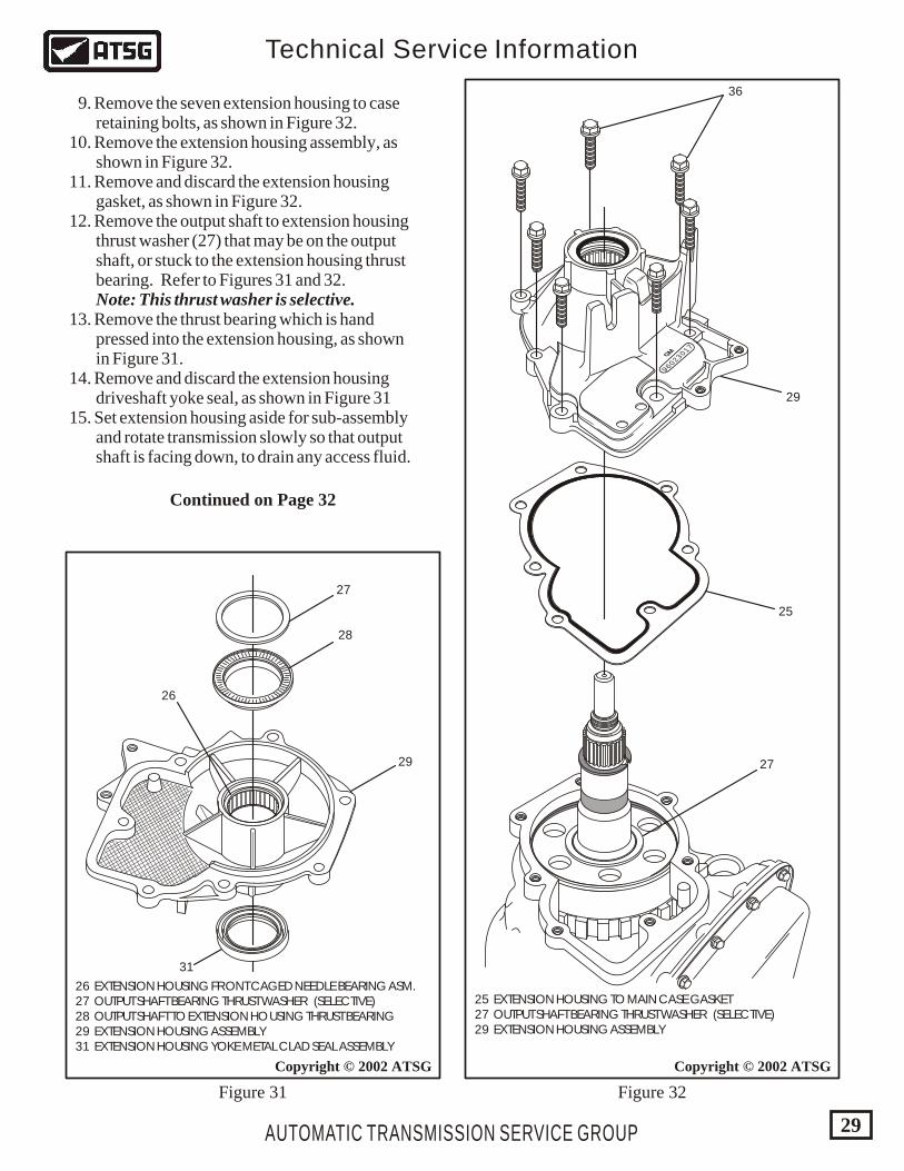
25 EXTENSION HOUSING TO MAIN CASE GASKET 27 OUTPUT SHAFT BEARING THRUST WASHER (SELECTIVE) 29 EXTENSION HOUSING ASSEMBLY
26 EXTENSION HOUSING FRONT CAGED NEEDLE BEARING ASM. 27 OUTPUT SHAFT BEARING THRUST WASHER (SELECTIVE) 28 OUTPUT SHAFT TO EXTENSION HOUSING THRUST BEARING 29 EXTENSION HOUSING ASSEMBLY 31 EXTENSION HOUSING YOKE METAL CLAD SEAL ASSEMBLY
Figure 32Figure 31
9. Remove the seven extension housing to case retaining bolts, as shown in Figure 32. 10. Remove the extension housing assembly, as shown in Figure 32. 11. Remove and discard the extension housing gasket, as shown in Figure 32. 12. Remove the output shaft to extension housing thrust washer (27) that may be on the output shaft, or stuck to the extension housing thrust bearing. Refer to Figures 31 and 32. Note: This thrust washer is selective. 13. Remove the thrust bearing which is hand pressed into the extension housing, as shown in Figure 31. 14. Remove and discard the extension housing driveshaft yoke seal, as shown in Figure 31 15. Set extension housing aside for sub-assembly and rotate transmission slowly so that output shaft is facing down, to drain any access fluid.
27
28
29
31
26
96023017GM
36
29
25
27
Continued on Page 32
AUTOMATIC TRANSMISSION SERVICE GROUP
Technical Service Information
30
Copyright © 2002 ATSG
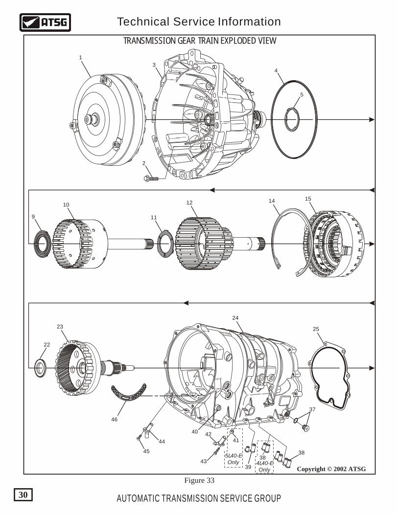
TRANSMISSION GEAR TRAIN EXPLODED VIEW
1
2
34
9
10
11
12 14 15
5
22
23
24
25
37
3838
4L40-EOnly
5L40-EOnly
39
4142
43
44
45
46
40
Figure 33
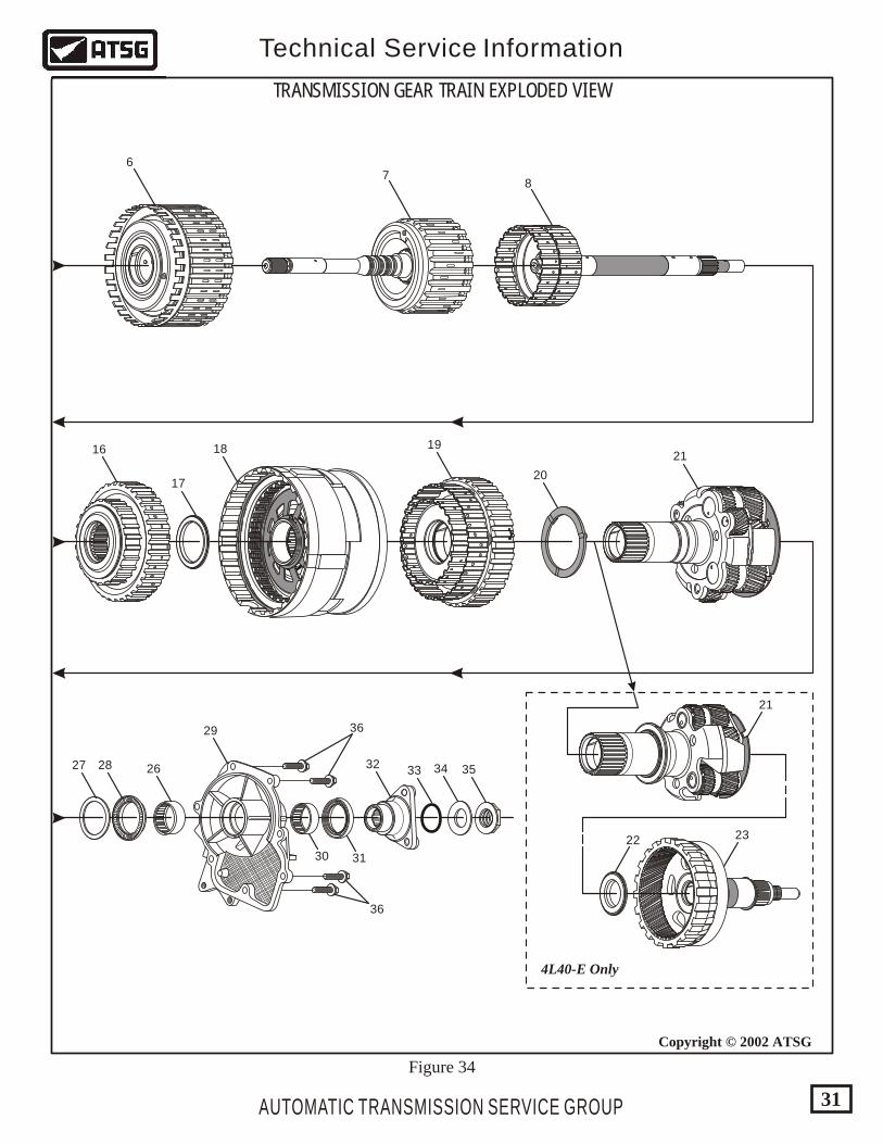
TRANSMISSION GEAR TRAIN EXPLODED VIEW
AUTOMATIC TRANSMISSION SERVICE GROUP
Technical Service Information
31
Copyright © 2002 ATSG
4L40-E Only
67
8
16
17
18 19
20
21
21
22 23
Figure 34
27 28
29
32 33 34 35
30 31
36
36
26
AUTOMATIC TRANSMISSION SERVICE GROUP
Technical Service Information
32
Copyright © 2002 ATSG
1 TORQUE CONVERTER ASSEMBLY (MODEL SENSITIVE) 2 TORQUE CONVERTER HOUSING TO MAIN CASE BOLTS (7) 3 CONVERTER HOUSING AND OIL PUMP ASSEMBLY 4 CONVERTER HOUSING TO MAIN CASE "D" RING SEAL 5 REVERSE CLUTCH HOUSING THRUST WASHER (SELECTIVE) 6 DIRECT AND REVERSE CLUTCH HOUSING ASSEMBLY 7 FORWARD AND COAST CLUTCH HOUSING ASSEMBLY 8 FORWARD SPRAG ASSEMBLY AND INPUT SUN GEAR SHAFT 9 DIRECT CLUTCH HUB THRUST WASHER 10 DIRECT CLUTCH HUB AND SHAFT ASSEMBLY 11 DIRECT CLUTCH HUB TO O.D. CLUTCH HUB THRUST WASHER 12 O.D. CLUTCH HUB AND INTERMEDIATE SPRAG ASSEMBLY 14 INTERM. AND O.D. CLUTCH HOUSING SNAP RING (SELECTIVE) 15 INTERMEDIATE AND OVERDRIVE CLUTCH HOUSING ASSEMBLY 16 LOW SPRAG ASSEMBLY 17 LOW SPRAG TO CENTER SUPPORT THRUST BEARING 18 CENTER SUPPORT ASSEMBLY 19 2ND CLUTCH SPRAG AND HUB ASSEMBLY (5L40-E ONLY) 20 2ND CLUTCH SPRAG THRUST WASHER (5L40-E ONLY) 21 PLANETARY CARRIER ASSEMBLY 22 PLANETARY CARRIER TO OUTPUT SHAFT THRUST BEARING 23 OUTPUT SHAFT AND INTERNAL RING GEAR ASSEMBLY 24 TRANSMISSION MAIN CASE ASSEMBLY
25 EXTENSION HOUSING TO MAIN CASE GASKET 26 FRONT CAGED NEEDLE BEARING IN EXTENSION HOUSING 27 OUTPUT SHAFT TO EXT. HSG. BEARING WASHER (SELECTIVE) 28 OUTPUT SHAFT TO EXTENSION HOUSING THRUST BEARING 29 EXTENSION HOUSING ASSEMBLY 30 REAR CAGED NEEDLE BEARING IN EXTENSION HOUSING 31 EXTENSION HOUSING YOKE SEAL ASSEMBLY 32 DRIVESHAFT YOKE ASSEMBLY 33 OUTPUT SHAFT TO YOKE "O" RING SEAL 34 DRIVESHAFT YOKE RETAINING WASHER 35 DRIVESHAFT YOKE RETAINING NUT 36 EXTENSION HOUSING RETAINING BOLTS (7) 37 TRANSMISSION FILL PLUG AND "O" RING 38 CENTER SUPPORT OIL PASSAGE SLEEVE AND SEAL ASSEMBLY 39 O.D./INTERMEDIATE OIL PASSAGE SLEEVE AND SEAL ASSEMBLY 40 TRANSMISSION PRESSURE TEST PLUG 41 OUTPUT SPEED SENSOR SPACER 42 OUTPUT SPEED SENSOR 43 OUTPUT SPEED SENSOR RETAINING BOLT 44 INPUT SPEED SENSOR 45 INPUT SPEED SENSOR RETAINING BOLT 46 PUMP COVER TO MAIN CASE MOLDED GASKET
Figures 33 and 34 Legend
Legend For Figures 33 and 34
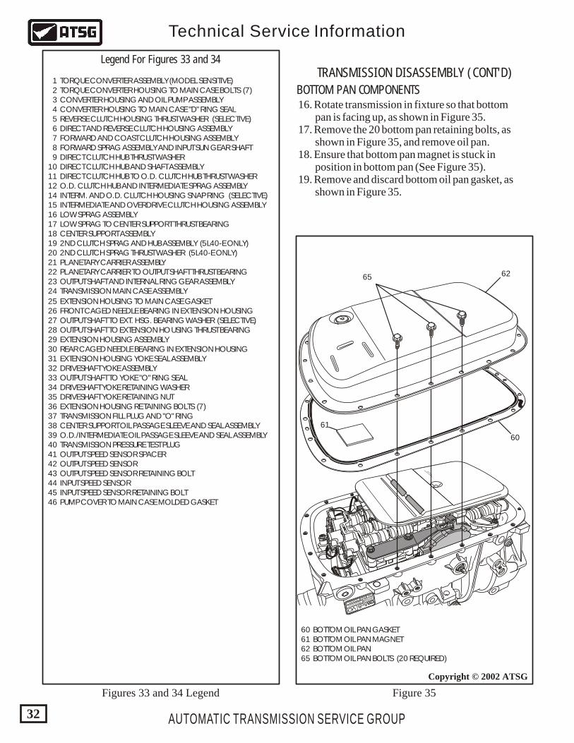
Figure 35
TRANSMISSION DISASSEMBLY (CONT'D)
BOTTOM PAN COMPONENTS 16. Rotate transmission in fixture so that bottom pan is facing up, as shown in Figure 35. 17. Remove the 20 bottom pan retaining bolts, as shown in Figure 35, and remove oil pan. 18. Ensure that bottom pan magnet is stuck in position in bottom pan (See Figure 35). 19. Remove and discard bottom oil pan gasket, as shown in Figure 35.
HYDRAMATIC
STRASBOURG
MADE IN FRANCESERIAL NO.
1 423 875
0139781 96022832
P08
VO
_ __ _
PART NO.
TCM
CAL.
GM
96020473
96020566
307
IBS FILTRAN
MADE IN G
ERMANY
65 62
60
61
60 BOTTOM OIL PAN GASKET 61 BOTTOM OIL PAN MAGNET 62 BOTTOM OIL PAN 65 BOTTOM OIL PAN BOLTS (20 REQUIRED)
AUTOMATIC TRANSMISSION SERVICE GROUP
Technical Service Information
33
Copyright © 2002 ATSG
Figure 37Figure 36
Copyright © 2002 ATSG
HYDRAMATIC
STRASBOURG
MADE IN FRANCESERIAL NO.
1 423 875
0139781 96022832
P08
VO
_ __ _
PART NO.
TCM
CAL.
GM
96020473
96020566
307
IBS FILTRAN
MADE IN G
ERMANY
59
58
57
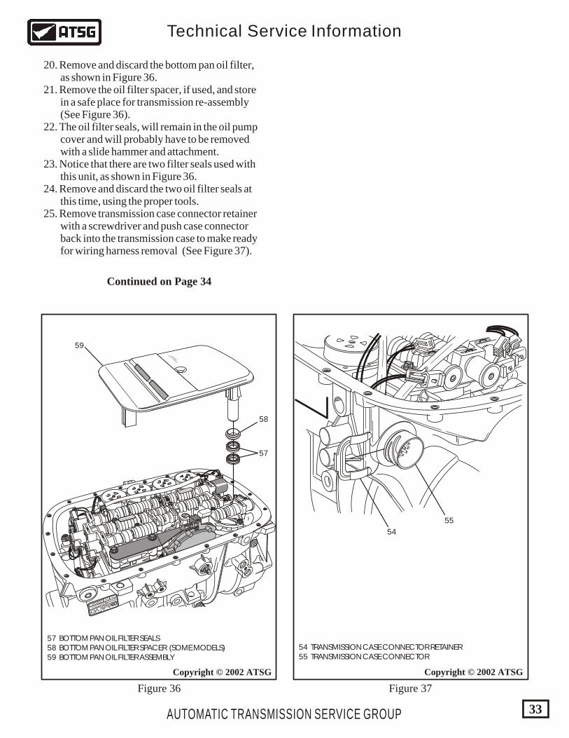
57 BOTTOM PAN OIL FILTER SEALS 58 BOTTOM PAN OIL FILTER SPACER (SOME MODELS) 59 BOTTOM PAN OIL FILTER ASSEMBLY
54 TRANSMISSION CASE CONNECTOR RETAINER 55 TRANSMISSION CASE CONNECTOR
55
54
20. Remove and discard the bottom pan oil filter, as shown in Figure 36. 21. Remove the oil filter spacer, if used, and store in a safe place for transmission re-assembly (See Figure 36). 22. The oil filter seals, will remain in the oil pump cover and will probably have to be removed with a slide hammer and attachment. 23. Notice that there are two filter seals used with this unit, as shown in Figure 36. 24. Remove and discard the two oil filter seals at this time, using the proper tools. 25. Remove transmission case connector retainer with a screwdriver and push case connector back into the transmission case to make ready for wiring harness removal (See Figure 37).
Continued on Page 34
AUTOMATIC TRANSMISSION SERVICE GROUP
Technical Service Information
34
Copyright © 2002 ATSG
BOTTOM PAN COMPONENTS
TRANSMISSION DISASSEMBLY (CONT'D)
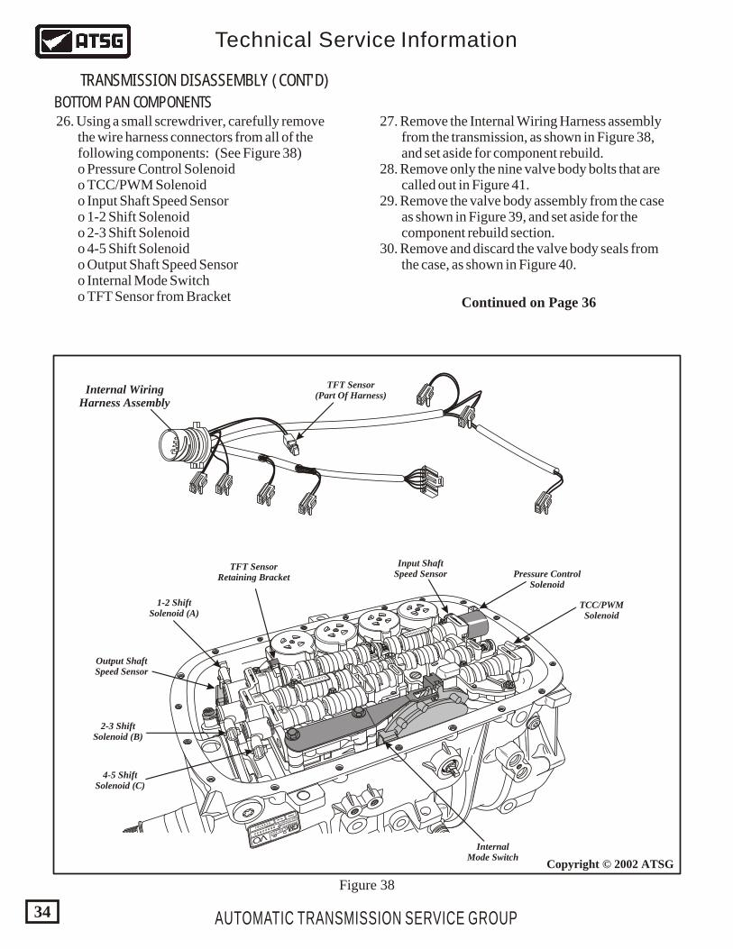
26. Using a small screwdriver, carefully remove the wire harness connectors from all of the following components: (See Figure 38) o Pressure Control Solenoid o TCC/PWM Solenoid o Input Shaft Speed Sensor o 1-2 Shift Solenoid o 2-3 Shift Solenoid o 4-5 Shift Solenoid o Output Shaft Speed Sensor o Internal Mode Switch o TFT Sensor from Bracket
27. Remove the Internal Wiring Harness assembly from the transmission, as shown in Figure 38, and set aside for component rebuild. 28. Remove only the nine valve body bolts that are called out in Figure 41. 29. Remove the valve body assembly from the case as shown in Figure 39, and set aside for the component rebuild section. 30. Remove and discard the valve body seals from the case, as shown in Figure 40.
HYDRAMATIC
STRASBOURG
MADE IN FRANCESERIAL NO.
1 423 875
0139781 96022832
P08
VO
_ __ _
PART NO.
TCM
CAL.
GM
96020473
96020566
307
Pressure ControlSolenoid
Input ShaftSpeed Sensor
TFT Sensor(Part Of Harness)
TFT SensorRetaining Bracket
Internal WiringHarness Assembly
Output ShaftSpeed Sensor
1-2 ShiftSolenoid (A)
2-3 ShiftSolenoid (B)
4-5 ShiftSolenoid (C)
InternalMode Switch
TCC/PWMSolenoid
Figure 38
Continued on Page 36
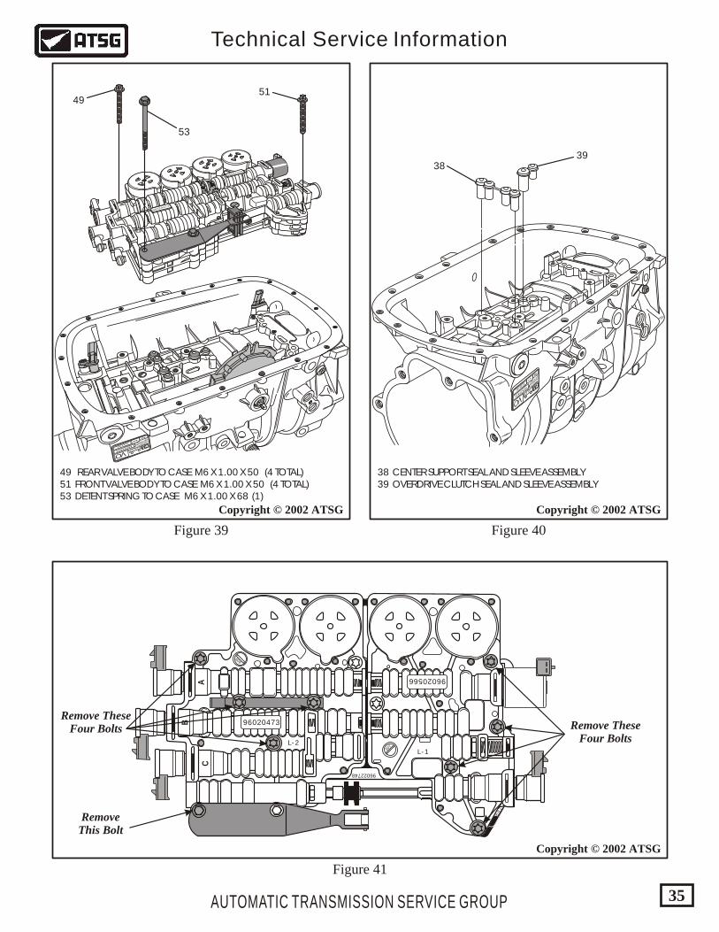
38 CENTER SUPPORT SEAL AND SLEEVE ASSEMBLY 39 OVERDRIVE CLUTCH SEAL AND SLEEVE ASSEMBLY
AUTOMATIC TRANSMISSION SERVICE GROUP
Technical Service Information
35
Copyright © 2002 ATSG
Copyright © 2002 ATSG
Figure 41
96022748
78
9
96020566
96020473
CA
B
307
308
L - 2
L -1
49 REAR VALVE BODY TO CASE M6 X 1.00 X 50 (4 TOTAL) 51 FRONT VALVE BODY TO CASE M6 X 1.00 X 50 (4 TOTAL) 53 DETENT SPRING TO CASE M6 X 1.00 X 68 (1)
Copyright © 2002 ATSG
Figure 39 Figure 40
96020473
96020566
307
HYDRAMATIC
STRASBOURG
MADE IN FRANCESERIAL NO.
1 423 875
0139781 96022832
P08
VO
_ __ _
PART NO.
TCM
CAL.
GM
4951
3839
53
Remove TheseFour Bolts
RemoveThis Bolt
Remove TheseFour Bolts
HYDRAMATIC
STRASBOURG
MADE IN FRANCE
SERIAL NO. 1 423 875
013978196022832
P08
VO
_ __ _
PART NO.
TCM
CAL.
GM
44 INPUT SHAFT SPEED SENSOR 45 INPUT SPEED SENSOR RETAINING BOLT
AUTOMATIC TRANSMISSION SERVICE GROUP
Technical Service Information
36
Copyright © 2002 ATSG
Copyright © 2002 ATSG Copyright © 2002 ATSG
BOTTOM PAN COMPONENTS
TRANSMISSION DISASSEMBLY (CONT'D)
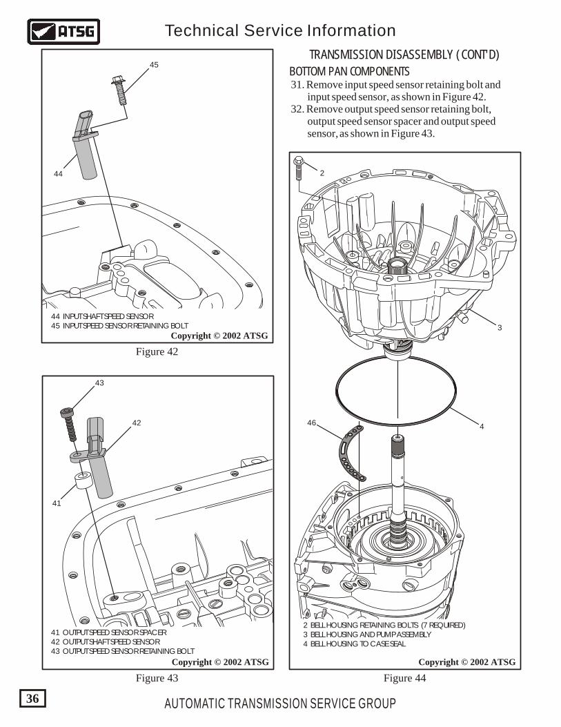
31. Remove input speed sensor retaining bolt and input speed sensor, as shown in Figure 42. 32. Remove output speed sensor retaining bolt, output speed sensor spacer and output speed sensor, as shown in Figure 43.
41 OUTPUT SPEED SENSOR SPACER 42 OUTPUT SHAFT SPEED SENSOR 43 OUTPUT SPEED SENSOR RETAINING BOLT
2 BELL HOUSING RETAINING BOLTS (7 REQUIRED) 3 BELL HOUSING AND PUMP ASSEMBLY 4 BELL HOUSING TO CASE SEAL
41
42 46
2
3
4
44
45
43
Figure 42
Figure 43 Figure 44
AUTOMATIC TRANSMISSION SERVICE GROUP
Technical Service Information
37
Copyright © 2002 ATSG
6
7
Copyright © 2002 ATSG
Forward And Reverse DrumsRemoved As An Assembly
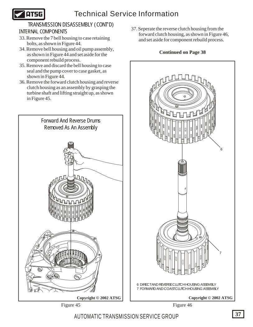
6 DIRECT AND REVERSE CLUTCH HOUSING ASSEMBLY 7 FORWARD AND COAST CLUTCH HOUSING ASSEMBLY
Figure 45 Figure 46
33. Remove the 7 bell housing to case retaining bolts, as shown in Figure 44. 34. Remove bell housing and oil pump assembly, as shown in Figure 44 and set aside for the component rebuild process. 35. Remove and discard the bell housing to case seal and the pump cover to case gasket, as shown in Figure 44. 36. Remove the forward clutch housing and reverse clutch housing as an assembly by grasping the turbine shaft and lifting straight up, as shown in Figure 45.
37. Seperate the reverse clutch housing from the forward clutch housing, as shown in Figure 46, and set aside for component rebuild process.
INTERNAL COMPONENTS
TRANSMISSION DISASSEMBLY (CONT'D)
Continued on Page 38
9 DIRECT CLUTCH HUB THRUST WASHER 10 DIRECT CLUTCH HUB AND SHAFT ASSEMBLY
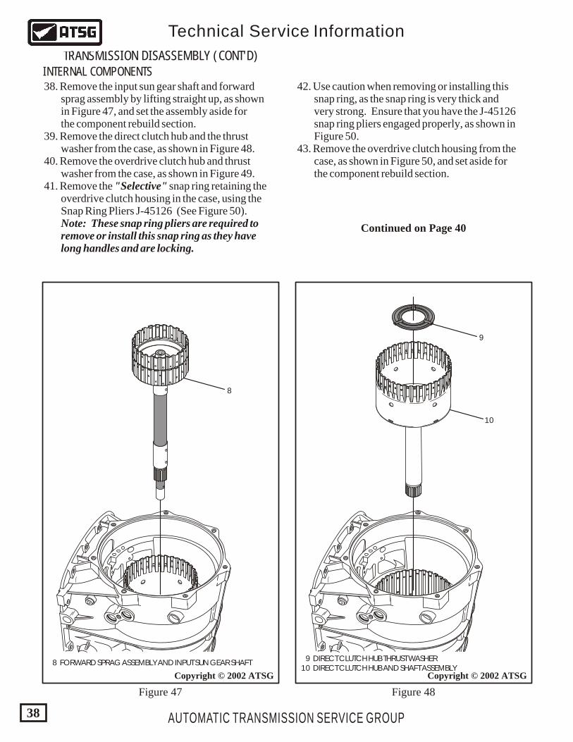
8
10
9
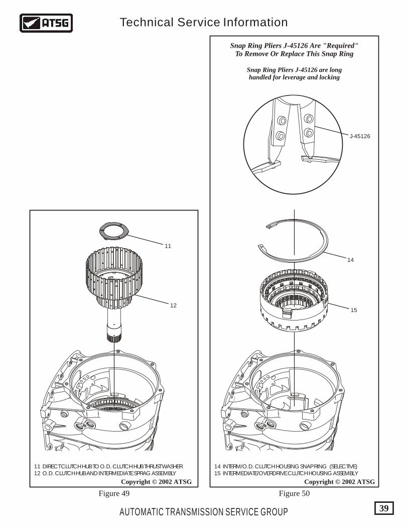
38. Remove the input sun gear shaft and forward sprag assembly by lifting straight up, as shown in Figure 47, and set the assembly aside for the component rebuild section. 39. Remove the direct clutch hub and the thrust washer from the case, as shown in Figure 48. 40. Remove the overdrive clutch hub and thrust washer from the case, as shown in Figure 49. 41. Remove the "Selective" snap ring retaining the overdrive clutch housing in the case, using the Snap Ring Pliers J-45126 (See Figure 50). Note: These snap ring pliers are required to remove or install this snap ring as they have long handles and are locking.
42. Use caution when removing or installing this snap ring, as the snap ring is very thick and very strong. Ensure that you have the J-45126 snap ring pliers engaged properly, as shown in Figure 50. 43. Remove the overdrive clutch housing from the case, as shown in Figure 50, and set aside for the component rebuild section.
INTERNAL COMPONENTS
TRANSMISSION DISASSEMBLY (CONT'D)
AUTOMATIC TRANSMISSION SERVICE GROUP
Technical Service Information
38
Copyright © 2002 ATSGCopyright © 2002 ATSG
8 FORWARD SPRAG ASSEMBLY AND INPUT SUN GEAR SHAFT
Figure 47 Figure 48
Continued on Page 40
12
11
AUTOMATIC TRANSMISSION SERVICE GROUP
Technical Service Information
39
Copyright © 2002 ATSGCopyright © 2002 ATSG
Figure 49 Figure 50
14
J-45126
15
14 INTERM/O.D. CLUTCH HOUSING SNAP RING (SELECTIVE) 15 INTERMEDIATE/OVERDRIVE CLUTCH HOUSING ASSEMBLY
11 DIRECT CLUTCH HUB TO O.D. CLUTCH HUB THRUST WASHER 12 O.D. CLUTCH HUB AND INTERMEDIATE SPRAG ASSEMBLY
Snap Ring Pliers J-45126 Are "Required"To Remove Or Replace This Snap Ring
Snap Ring Pliers J-45126 are longhandled for leverage and locking
16
17
18 CENTER SUPPORT ASSEMBLY
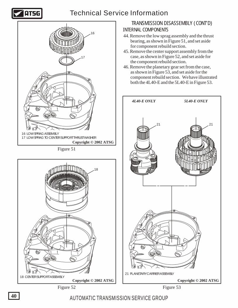
16 LOW SPRAG ASSEMBLY 17 LOW SPRAG TO CENTER SUPPORT THRUST WASHER
44. Remove the low sprag assembly and the thrust bearing, as shown in Figure 51, and set aside for component rebuild section. 45. Remove the center support assembly from the case, as shown in Figure 52, and set aside for the component rebuild section. 46. Remove the planetary gear set from the case, as shown in Figure 53, and set aside for the component rebuild section. We have illustrated both the 4L40-E and the 5L40-E in Figure 53.
INTERNAL COMPONENTS
TRANSMISSION DISASSEMBLY (CONT'D)
AUTOMATIC TRANSMISSION SERVICE GROUP
Technical Service Information
40
Copyright © 2002 ATSG
Copyright © 2002 ATSG
18
Figure 52 Figure 53
Figure 51
2121
21 PLANETARY CARRIER ASSEMBLY
Copyright © 2002 ATSG
5L40-E ONLY4L40-E ONLY
AUTOMATIC TRANSMISSION SERVICE GROUP
Technical Service Information
41
Copyright © 2002 ATSG
2222
2323
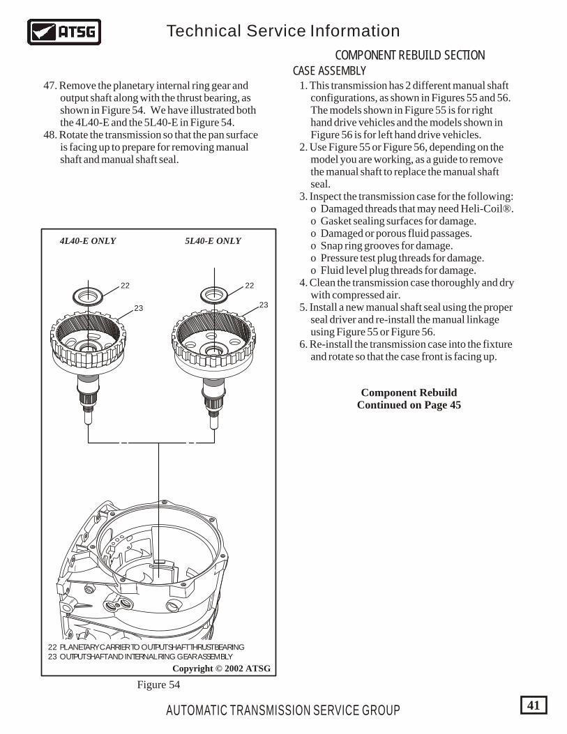
22 PLANETARY CARRIER TO OUTPUT SHAFT THRUST BEARING 23 OUTPUT SHAFT AND INTERNAL RING GEAR ASSEMBLY
5L40-E ONLY4L40-E ONLY
Figure 54
47. Remove the planetary internal ring gear and output shaft along with the thrust bearing, as shown in Figure 54. We have illustrated both the 4L40-E and the 5L40-E in Figure 54. 48. Rotate the transmission so that the pan surface is facing up to prepare for removing manual shaft and manual shaft seal.
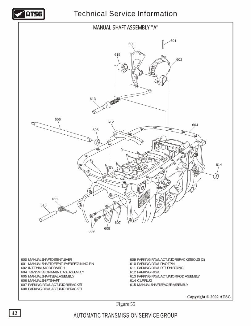
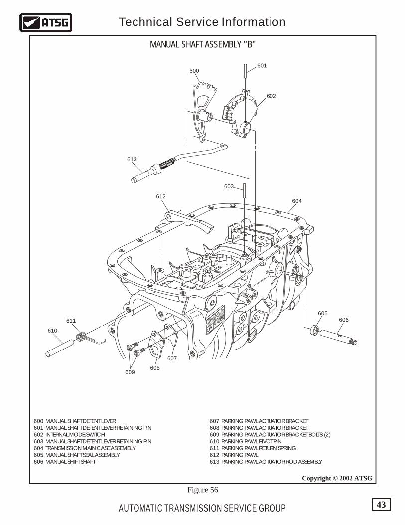
1. This transmission has 2 different manual shaft configurations, as shown in Figures 55 and 56. The models shown in Figure 55 is for right hand drive vehicles and the models shown in Figure 56 is for left hand drive vehicles. 2. Use Figure 55 or Figure 56, depending on the model you are working, as a guide to remove the manual shaft to replace the manual shaft seal. 3. Inspect the transmission case for the following: o Damaged threads that may need Heli-Coil®. o Gasket sealing surfaces for damage. o Damaged or porous fluid passages. o Snap ring grooves for damage. o Pressure test plug threads for damage. o Fluid level plug threads for damage. 4. Clean the transmission case thoroughly and dry with compressed air. 5. Install a new manual shaft seal using the proper seal driver and re-install the manual linkage using Figure 55 or Figure 56. 6. Re-install the transmission case into the fixture and rotate so that the case front is facing up.
CASE ASSEMBLY
COMPONENT REBUILD SECTION
Component RebuildContinued on Page 45
HYDRAMATIC
STRASBOURG
MADE IN FRANCE
SERIAL NO. 1 423 875
013978196022832
P08
VO
_ __ _
PART NO.
TCM
CAL.
GM
AUTOMATIC TRANSMISSION SERVICE GROUP
Technical Service Information
42
Copyright © 2002 ATSG
615
600601
602
604612
613
611
610
607
608609
605
606
614
609 PARKING PAWL ACTUATOR BRACKET BOLTS (2) 610 PARKING PAWL PIVOT PIN 611 PARKING PAWL RETURN SPRING 612 PARKING PAWL 613 PARKING PAWL ACTUATOR ROD ASSEMBLY 614 CUP PLUG 615 MANUAL SHAFT SPACER ASSEMBLY
600 MANUAL SHAFT DETENT LEVER 601 MANUAL SHAFT DETENT LEVER RETAINING PIN 602 INTERNAL MODE SWITCH 604 TRANSMISSION MAIN CASE ASSEMBLY 605 MANUAL SHAFT SEAL ASSEMBLY 606 MANUAL SHIFT SHAFT 607 PARKING PAWL ACTUATOR BRACKET 608 PARKING PAWL ACTUATOR BRACKET
MANUAL SHAFT ASSEMBLY "A"
Figure 55
HYDRAMATIC
STRASBOURG
MADE IN FRANCE
SERIAL NO. 1 423 875
013978196022832
P08
VO
_ __ _
PART NO.
TCM
CAL.
GM
AUTOMATIC TRANSMISSION SERVICE GROUP
Technical Service Information
43
Copyright © 2002 ATSG
600601
602
604
603
612
613
611
610
607
608609
605606
607 PARKING PAWL ACTUATOR BRACKET 608 PARKING PAWL ACTUATOR BRACKET 609 PARKING PAWL ACTUATOR BRACKET BOLTS (2) 610 PARKING PAWL PIVOT PIN 611 PARKING PAWL RETURN SPRING 612 PARKING PAWL 613 PARKING PAWL ACTUATOR ROD ASSEMBLY
600 MANUAL SHAFT DETENT LEVER 601 MANUAL SHAFT DETENT LEVER RETAINING PIN 602 INTERNAL MODE SWITCH 603 MANUAL SHAFT DETENT LEVER RETAINING PIN 604 TRANSMISSION MAIN CASE ASSEMBLY 605 MANUAL SHAFT SEAL ASSEMBLY 606 MANUAL SHIFT SHAFT
MANUAL SHAFT ASSEMBLY "B"
Figure 56
AUTOMATIC TRANSMISSION SERVICE GROUP
Technical Service Information
44
Copyright © 2002 ATSG
203
233
233
232215
TO FIGURE 58
214
213212 211
211238
239
236237
234
234
235
210209
208
207 206205
204
204
202
240 241
200
199
203
201
6 66 66 66 6
1/8
226
2.1226
2.1226
2.1226
2.1
nat
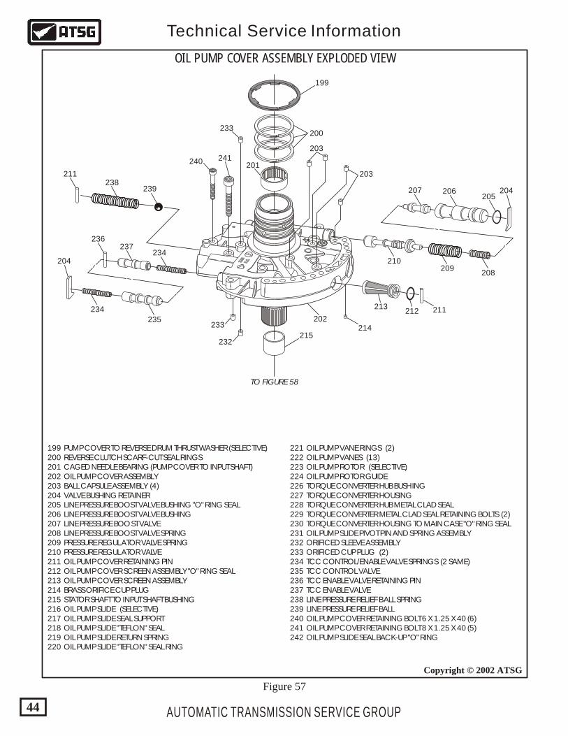
OIL PUMP COVER ASSEMBLY EXPLODED VIEW
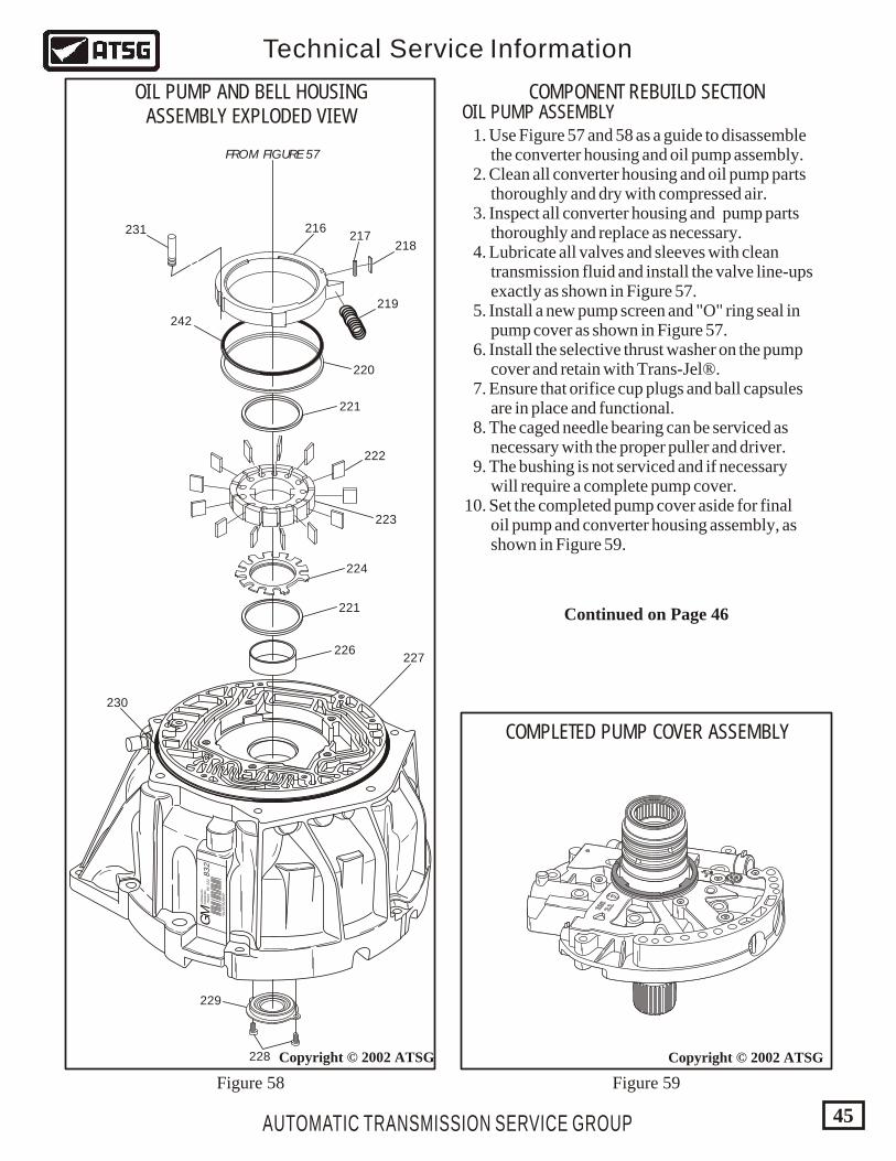
199 PUMP COVER TO REVERSE DRUM THRUST WASHER (SELECTIVE) 200 REVERSE CLUTCH SCARF-CUT SEAL RINGS 201 CAGED NEEDLE BEARING (PUMP COVER TO INPUT SHAFT) 202 OIL PUMP COVER ASSEMBLY 203 BALL CAPSULE ASSEMBLY (4) 204 VALVE BUSHING RETAINER 205 LINE PRESSURE BOOST VALVE BUSHING "O" RING SEAL 206 LINE PRESSURE BOOST VALVE BUSHING 207 LINE PRESSURE BOOST VALVE 208 LINE PRESSURE BOOST VALVE SPRING 209 PRESSURE REGULATOR VALVE SPRING 210 PRESSURE REGULATOR VALVE 211 OIL PUMP COVER RETAINING PIN 212 OIL PUMP COVER SCREEN ASSEMBLY "O" RING SEAL 213 OIL PUMP COVER SCREEN ASSEMBLY 214 BRASS ORIFICE CUP PLUG 215 STATOR SHAFT TO INPUT SHAFT BUSHING 216 OIL PUMP SLIDE (SELECTIVE) 217 OIL PUMP SLIDE SEAL SUPPORT 218 OIL PUMP SLIDE "TEFLON" SEAL 219 OIL PUMP SLIDE RETURN SPRING 220 OIL PUMP SLIDE "TEFLON" SEAL RING
221 OIL PUMP VANE RINGS (2) 222 OIL PUMP VANES (13) 223 OIL PUMP ROTOR (SELECTIVE) 224 OIL PUMP ROTOR GUIDE 226 TORQUE CONVERTER HUB BUSHING 227 TORQUE CONVERTER HOUSING 228 TORQUE CONVERTER HUB METAL CLAD SEAL 229 TORQUE CONVERTER METAL CLAD SEAL RETAINING BOLTS (2) 230 TORQUE CONVERTER HOUSING TO MAIN CASE "O" RING SEAL 231 OIL PUMP SLIDE PIVOT PIN AND SPRING ASSEMBLY 232 ORIFICED SLEEVE ASSEMBLY 233 ORIFICED CUP PLUG (2) 234 TCC CONTROL/ENABLE VALVE SPRINGS (2 SAME) 235 TCC CONTROL VALVE 236 TCC ENABLE VALVE RETAINING PIN 237 TCC ENABLE VALVE 238 LINE PRESSURE RELIEF BALL SPRING 239 LINE PRESSURE RELIEF BALL 240 OIL PUMP COVER RETAINING BOLT 6 X 1.25 X 40 (6) 241 OIL PUMP COVER RETAINING BOLT 8 X 1.25 X 40 (5) 242 OIL PUMP SLIDE SEAL BACK-UP "O" RING
Figure 57
AUTOMATIC TRANSMISSION SERVICE GROUP
Technical Service Information
45
COMPONENT REBUILD SECTIONOIL PUMP ASSEMBLY
Copyright © 2002 ATSG
GM
832
96 022
HYD
RAM
ATIC
STR
AS
BU
RG
FRAN
CE
*0139781R
VO
*
FROM FIGURE 57
216217
218
219
220
221
222
223
224
221
226
228
229
227
230
231
242
OIL PUMP AND BELL HOUSINGASSEMBLY EXPLODED VIEW
Figure 58 Figure 59
1. Use Figure 57 and 58 as a guide to disassemble the converter housing and oil pump assembly. 2. Clean all converter housing and oil pump parts thoroughly and dry with compressed air. 3. Inspect all converter housing and pump parts thoroughly and replace as necessary. 4. Lubricate all valves and sleeves with clean transmission fluid and install the valve line-ups exactly as shown in Figure 57. 5. Install a new pump screen and "O" ring seal in pump cover as shown in Figure 57. 6. Install the selective thrust washer on the pump cover and retain with Trans-Jel®. 7. Ensure that orifice cup plugs and ball capsules are in place and functional. 8. The caged needle bearing can be serviced as necessary with the proper puller and driver. 9. The bushing is not serviced and if necessary will require a complete pump cover. 10. Set the completed pump cover aside for final oil pump and converter housing assembly, as shown in Figure 59.
Copyright © 2002 ATSG
COMPLETED PUMP COVER ASSEMBLY
6 66 66 66 6
1/8
226
2.1226
2.1226
2.1226
2.1
nat
Continued on Page 46
AUTOMATIC TRANSMISSION SERVICE GROUP
Technical Service Information
46
GM
832
96 022
HYD
RAM
ATIC
STR
AS
BU
RG
FRAN
CE
*0139781R
VO
*
Copyright © 2002 ATSG
GM
832
96 022
HYD
RAM
ATIC
STR
AS
BU
RG
FRAN
CE
*0139781R
VO
*
Copyright © 2002 ATSG
ROTOR .001 - .0015SLIDE .002 - .0025
GM
832
96 022
HYD
RAM
ATIC
STR
AS
BU
RG
FRAN
CE
*0139781R
VO
*
226
227
Copyright © 2002 ATSG
226 TORQUE CONVERTER HOUSING BUSHING 227 TORQUE CONVERTER HOUSING ASSEMBLY
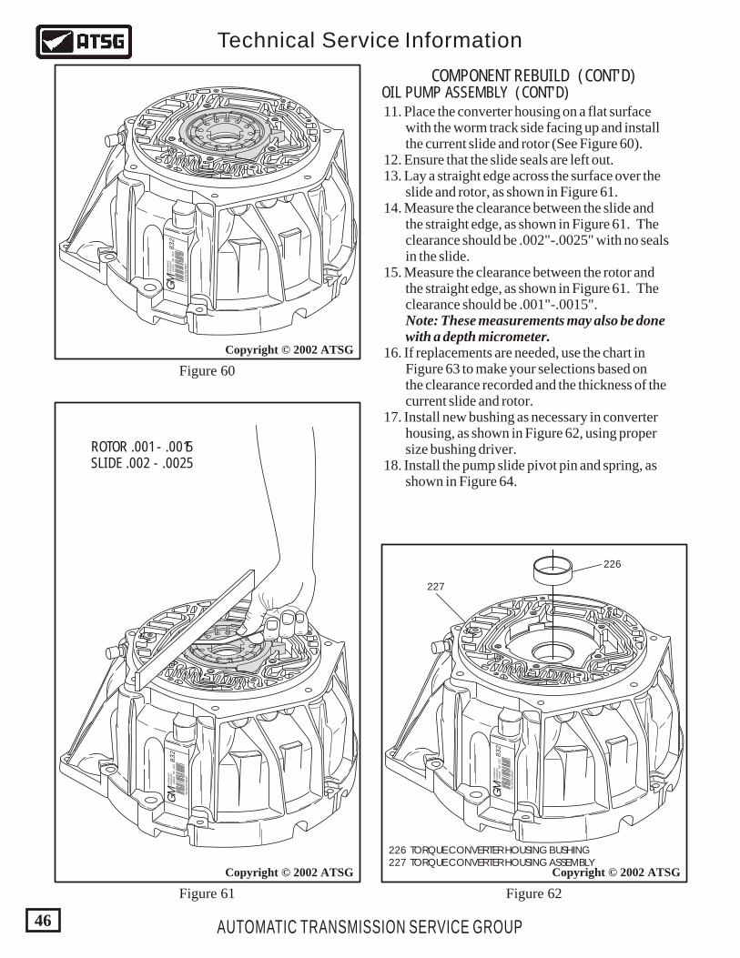
COMPONENT REBUILD (CONT'D)OIL PUMP ASSEMBLY (CONT'D) 11. Place the converter housing on a flat surface with the worm track side facing up and install the current slide and rotor (See Figure 60). 12. Ensure that the slide seals are left out. 13. Lay a straight edge across the surface over the slide and rotor, as shown in Figure 61. 14. Measure the clearance between the slide and the straight edge, as shown in Figure 61. The clearance should be .002"-.0025" with no seals in the slide. 15. Measure the clearance between the rotor and the straight edge, as shown in Figure 61. The clearance should be .001"-.0015". Note: These measurements may also be done with a depth micrometer. 16. If replacements are needed, use the chart in Figure 63 to make your selections based on the clearance recorded and the thickness of the current slide and rotor. 17. Install new bushing as necessary in converter housing, as shown in Figure 62, using proper size bushing driver. 18. Install the pump slide pivot pin and spring, as shown in Figure 64.
Figure 60
Figure 61 Figure 62
AUTOMATIC TRANSMISSION SERVICE GROUP
Technical Service Information
47
GM
832
96 022
HYD
RAM
ATIC
STR
AS
BU
RG
FRAN
CE
*0139781R
VO
*
216217
218
219
220
231
242
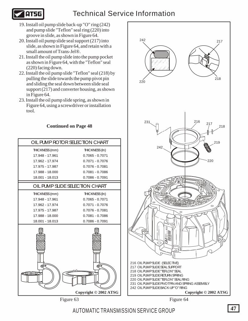
216 OIL PUMP SLIDE (SELECTIVE) 217 OIL PUMP SLIDE SEAL SUPPORT 218 OIL PUMP SLIDE "TEFLON" SEAL 219 OIL PUMP SLIDE RETURN SPRING 220 OIL PUMP SLIDE "TEFLON" SEAL RING 231 OIL PUMP SLIDE PIVOT PIN AND SPRING ASSEMBLY 242 OIL PUMP SLIDE BACK-UP "O" RING
Copyright © 2002 ATSG
217
218220
242
Copyright © 2002 ATSG
OIL PUMP ROTOR SELECTION CHARTOIL PUMP ROTOR SELECTION CHART
THICKNESS (mm)THICKNESS (mm)
THICKNESS (mm)THICKNESS (mm)
17.948 - 17.96117.948 - 17.961
17.948 - 17.96117.948 - 17.961
0.7065 - 0.70710.7065 - 0.7071
0.7065 - 0.70710.7065 - 0.7071
17.962 - 17.97417.962 - 17.974
17.962 - 17.97417.962 - 17.974
0.7071 - 0.70760.7071 - 0.7076
0.7071 - 0.70760.7071 - 0.7076
17.975 - 17.98717.975 - 17.987
17.975 - 17.98717.975 - 17.987
0.7076 - 0.70810.7076 - 0.7081
0.7076 - 0.70810.7076 - 0.7081
17.988 - 18.00017.988 - 18.000
17.988 - 18.00017.988 - 18.000
0.7081 - 0.70860.7081 - 0.7086
0.7081 - 0.70860.7081 - 0.7086
18.001 - 18.01318.001 - 18.013
18.001 - 18.01318.001 - 18.013
0.7086 - 0.70910.7086 - 0.7091
0.7086 - 0.70910.7086 - 0.7091
THICKNESS (In)THICKNESS (In)
THICKNESS (In)THICKNESS (In)
OIL PUMP SLIDE SELECTION CHARTOIL PUMP SLIDE SELECTION CHART
Figure 63 Figure 64
19. Install oil pump slide back-up "O" ring (242) and pump slide "Teflon" seal ring (220) into groove in slide, as shown in Figure 64. 20. Install oil pump slide seal support (217) into slide, as shown in Figure 64, and retain with a small amount of Trans-Jel®. 21. Install the oil pump slide into the pump pocket as shown in Figure 64, with the "Teflon" seal (220) facing down. 22. Install the oil pump slide "Teflon" seal (218) by pulling the slide towards the pump pivot pin and sliding the seal down between slide seal support (217) and converter housing, as shown in Figure 64. 23. Install the oil pump slide spring, as shown in Figure 64, using a screwdriver or installation tool.
Continued on Page 48
GM
832
96 022
HYD
RAM
ATIC
STR
AS
BU
RG
FRAN
CE
*0139781R
VO
*
221
222
223
224
221
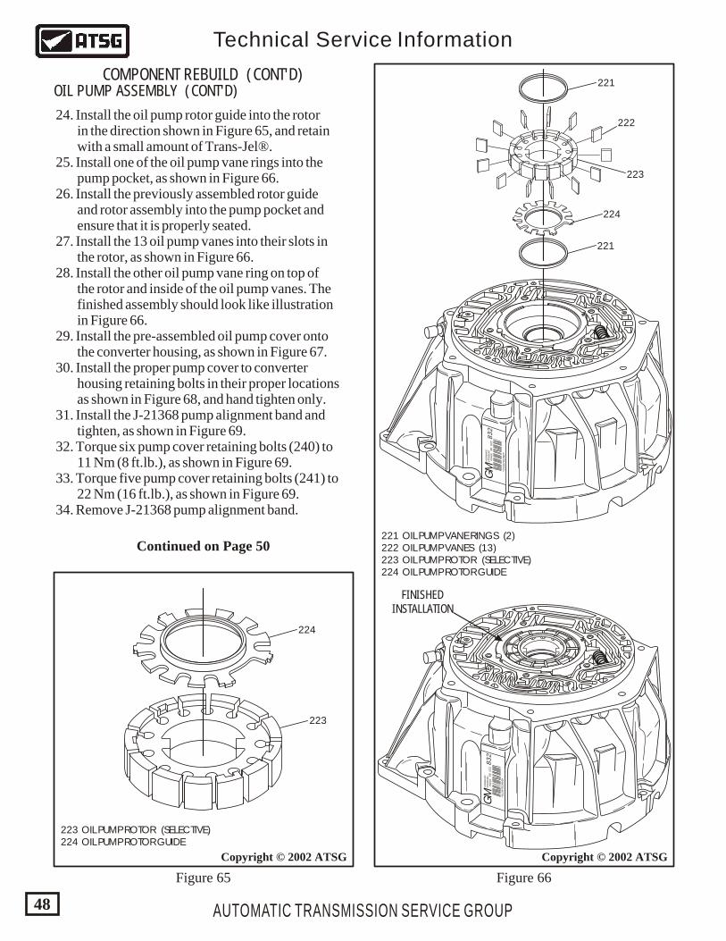
221 OIL PUMP VANE RINGS (2) 222 OIL PUMP VANES (13) 223 OIL PUMP ROTOR (SELECTIVE) 224 OIL PUMP ROTOR GUIDE
223 OIL PUMP ROTOR (SELECTIVE) 224 OIL PUMP ROTOR GUIDE
AUTOMATIC TRANSMISSION SERVICE GROUP
Technical Service Information
48
Copyright © 2002 ATSGCopyright © 2002 ATSG
224
FINISHEDINSTALLATION
223
COMPONENT REBUILD (CONT'D)OIL PUMP ASSEMBLY (CONT'D)
24. Install the oil pump rotor guide into the rotor in the direction shown in Figure 65, and retain with a small amount of Trans-Jel®. 25. Install one of the oil pump vane rings into the pump pocket, as shown in Figure 66. 26. Install the previously assembled rotor guide and rotor assembly into the pump pocket and ensure that it is properly seated. 27. Install the 13 oil pump vanes into their slots in the rotor, as shown in Figure 66. 28. Install the other oil pump vane ring on top of the rotor and inside of the oil pump vanes. The finished assembly should look like illustration in Figure 66. 29. Install the pre-assembled oil pump cover onto the converter housing, as shown in Figure 67. 30. Install the proper pump cover to converter housing retaining bolts in their proper locations as shown in Figure 68, and hand tighten only. 31. Install the J-21368 pump alignment band and tighten, as shown in Figure 69. 32. Torque six pump cover retaining bolts (240) to 11 Nm (8 ft.lb.), as shown in Figure 69. 33. Torque five pump cover retaining bolts (241) to 22 Nm (16 ft.lb.), as shown in Figure 69. 34. Remove J-21368 pump alignment band.
Figure 65 Figure 66
GM
832
96 022
HYD
RAM
ATIC
STR
AS
BU
RG
FRAN
CE
*0139781R
VO
*
Continued on Page 50
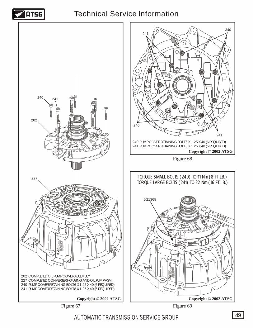
240 PUMP COVER RETAINING BOLT 6 X 1.25 X 40 (6 REQUIRED) 241 PUMP COVER RETAINING BOLT 8 X 1.25 X 40 (5 REQUIRED)
AUTOMATIC TRANSMISSION SERVICE GROUP
Technical Service Information
49
Copyright © 2002 ATSG
Copyright © 2002 ATSG
202 COMPLETED OIL PUMP COVER ASSEMBLY 227 COMPLETED CONVERTER HOUSING AND OIL PUMP ASM. 240 PUMP COVER RETAINING BOLT 6 X 1.25 X 40 (6 REQUIRED) 241 PUMP COVER RETAINING BOLT 8 X 1.25 X 40 (5 REQUIRED)
GM
832
96 022
HYD
RAM
ATIC
STR
AS
BU
RG
FRAN
CE
*0139781R
VO
*
6 66 66 66 6
1/8
226
2.1226
2.1226
2.1226
2.1
nat
202
240 241
227
GM
832
96 022
HYD
RAM
ATIC
STR
AS
BU
RG
FRAN
CE
*0139781R
VO
*
6 66 66 66 6
1/8
226
2.1226
2.1226
2.1226
2.1
nat
Snap-On
Copyright © 2002 ATSG
J-21368
Figure 67 Figure 69
Figure 68
240
240241
241
GMGM
2262262 . 12 . 1 n
at
na
t
9/9
9/9
1/8 1/8
TORQUE SMALL BOLTS (240) TO 11 Nm (8 FT.LB.)TORQUE LARGE BOLTS (241) TO 22 Nm (16 FT.LB.)
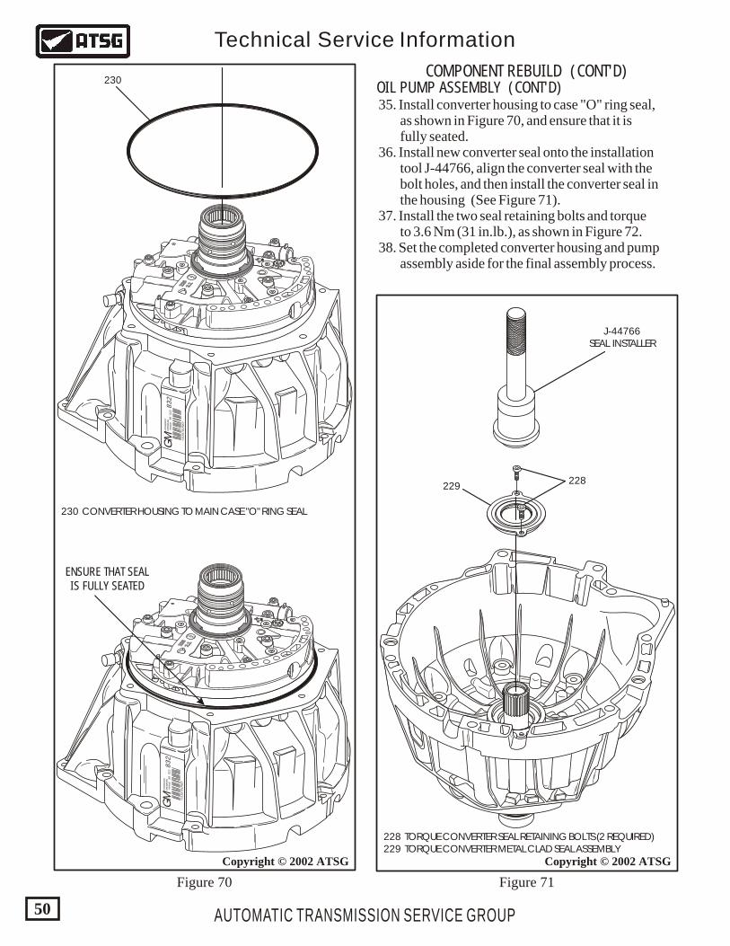
AUTOMATIC TRANSMISSION SERVICE GROUP
Technical Service Information
50
Copyright © 2002 ATSG
GM
832
96 022
HYD
RAM
ATIC
STR
AS
BU
RG
FRAN
CE
*0139781R
VO
*
6 66 66 66 6
1/8
226
2.1226
2.1226
2.1226
2.1
nat
230
GM
832
96 022
HYD
RAM
ATIC
STR
AS
BU
RG
FRAN
CE
*0139781R
VO
*
6 66 66 66 6
1/8
226
2.1226
2.1226
2.1226
2.1
nat
230 CONVERTER HOUSING TO MAIN CASE "O" RING SEAL
ENSURE THAT SEALIS FULLY SEATED
COMPONENT REBUILD (CONT'D)OIL PUMP ASSEMBLY (CONT'D) 35. Install converter housing to case "O" ring seal, as shown in Figure 70, and ensure that it is fully seated. 36. Install new converter seal onto the installation tool J-44766, align the converter seal with the bolt holes, and then install the converter seal in the housing (See Figure 71). 37. Install the two seal retaining bolts and torque to 3.6 Nm (31 in.lb.), as shown in Figure 72. 38. Set the completed converter housing and pump assembly aside for the final assembly process.
Figure 70 Figure 71
228 TORQUE CONVERTER SEAL RETAINING BOLTS (2 REQUIRED) 229 TORQUE CONVERTER METAL CLAD SEAL ASSEMBLY
Copyright © 2002 ATSG
228
J-44766SEAL INSTALLER
229
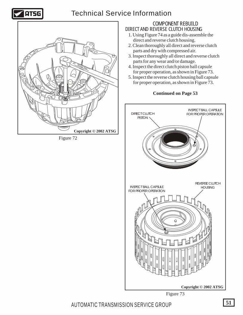
AUTOMATIC TRANSMISSION SERVICE GROUP
Technical Service Information
51
Snap-On
Copyright © 2002 ATSG
Figure 72
Figure 73
COMPONENT REBUILDDIRECT AND REVERSE CLUTCH HOUSING
Copyright © 2002 ATSG
INSPECT BALL CAPSULEFOR PROPER OPERATION
INSPECT BALL CAPSULEFOR PROPER OPERATION
REVERSE CLUTCHHOUSING
DIRECT CLUTCHPISTON
1. Using Figure 74 as a guide dis-assemble the direct and reverse clutch housing. 2. Clean thoroughly all direct and reverse clutch parts and dry with compressed air. 3. Inspect thoroughly all direct and reverse clutch parts for any wear and/or damage. 4. Inspect the direct clutch piston ball capsule for proper operation, as shown in Figure 73. 5. Inspect the reverse clutch housing ball capsule for proper operation, as shown in Figure 73.
Continued on Page 53
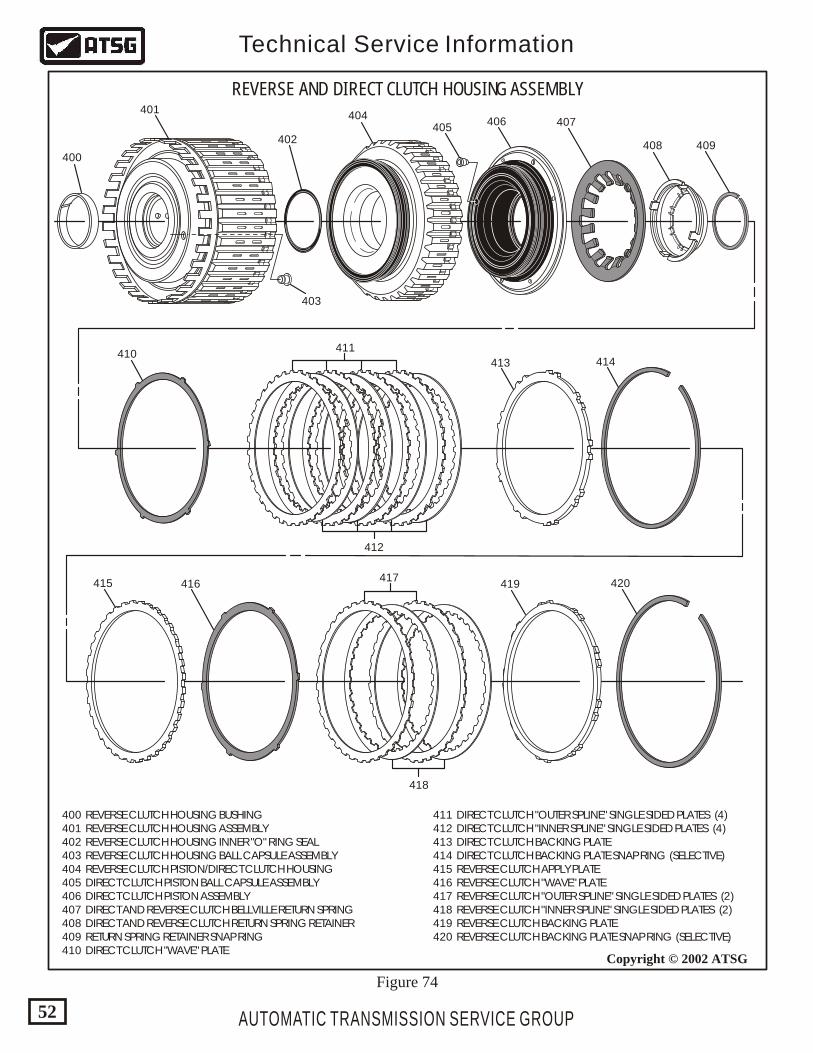
400 REVERSE CLUTCH HOUSING BUSHING 401 REVERSE CLUTCH HOUSING ASSEMBLY 402 REVERSE CLUTCH HOUSING INNER "O" RING SEAL 403 REVERSE CLUTCH HOUSING BALL CAPSULE ASSEMBLY 404 REVERSE CLUTCH PISTON/DIRECT CLUTCH HOUSING 405 DIRECT CLUTCH PISTON BALL CAPSULE ASSEMBLY 406 DIRECT CLUTCH PISTON ASSEMBLY 407 DIRECT AND REVERSE CLUTCH BELLVILLE RETURN SPRING 408 DIRECT AND REVERSE CLUTCH RETURN SPRING RETAINER 409 RETURN SPRING RETAINER SNAP RING 410 DIRECT CLUTCH "WAVE" PLATE
411 DIRECT CLUTCH "OUTER SPLINE" SINGLE SIDED PLATES (4) 412 DIRECT CLUTCH "INNER SPLINE" SINGLE SIDED PLATES (4) 413 DIRECT CLUTCH BACKING PLATE 414 DIRECT CLUTCH BACKING PLATE SNAP RING (SELECTIVE) 415 REVERSE CLUTCH APPLY PLATE 416 REVERSE CLUTCH "WAVE" PLATE 417 REVERSE CLUTCH "OUTER SPLINE" SINGLE SIDED PLATES (2) 418 REVERSE CLUTCH "INNER SPLINE" SINGLE SIDED PLATES (2) 419 REVERSE CLUTCH BACKING PLATE 420 REVERSE CLUTCH BACKING PLATE SNAP RING (SELECTIVE)
AUTOMATIC TRANSMISSION SERVICE GROUP
Technical Service Information
52
REVERSE AND DIRECT CLUTCH HOUSING ASSEMBLY
400
401
402
404405
406 407
408 409
410411
413 414
415 416417
419 420
418
412
403
Copyright © 2002 ATSG
Figure 74
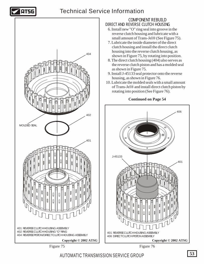
AUTOMATIC TRANSMISSION SERVICE GROUP
Technical Service Information
53
Copyright © 2002 ATSG
404
402
401
401 REVERSE CLUTCH HOUSING ASSEMBLY 402 REVERSE CLUTCH HOUSING "O" RING 404 REVERSE PISTON/DIRECT CLUTCH HOUSING ASSEMBLY
401 REVERSE CLUTCH HOUSING ASSEMBLY 406 DIRECT CLUTCH PISTON ASSEMBLY
Copyright © 2002 ATSG
COMPONENT REBUILDDIRECT AND REVERSE CLUTCH HOUSING 6. Install new "O" ring seal into groove in the reverse clutch housing and lubricate with a small amount of Trans-Jel® (See Figure 75). 7. Lubricate the inside diameter of the direct clutch housing and install the direct clutch housing into the reverse clutch housing, as shown in Figure 75, by rotating into position. 8. The direct clutch housing (404) also serves as the reverse clutch piston and has a molded seal as shown in Figure 75. 9. Install J-45133 seal protector onto the reverse housing, as shown in Figure 76. 10. Lubricate the molded seals with a small amount of Trans-Jel® and install direct clutch piston by rotating into position (See Figure 76).
Figure 75 Figure 76
401
J-45133
MOLDED SEAL
406
Continued on Page 54
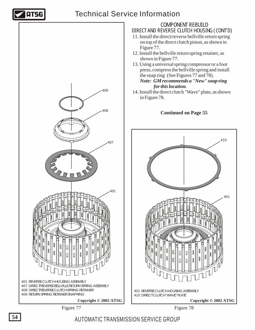
401 REVERSE CLUTCH HOUSING ASSEMBLY 407 DIRECT/REVERSE BELLVILLE RETURN SPRING ASSEMBLY 408 DIRECT/REVERSE CLUTCH SPRING RETAINER 409 RETURN SPRING RETAINER SNAP RING
401 REVERSE CLUTCH HOUSING ASSEMBLY 410 DIRECT CLUTCH "WAVE" PLATE
AUTOMATIC TRANSMISSION SERVICE GROUP
Technical Service Information
54
Copyright © 2002 ATSG
401
401
407
408
409
410
Copyright © 2002 ATSG
COMPONENT REBUILDDIRECT AND REVERSE CLUTCH HOUSING (CONT'D) 11. Install the direct/reverse bellville return spring on top of the direct clutch piston, as shown in Figure 77. 12. Install the bellville return spring retainer, as shown in Figure 77. 13. Using a universal spring compressor or a foot press, compress the bellville spring and install the snap ring (See Figures 77 and 78). Note: GM recommends a "New" snap ring for this location. 14. Install the direct clutch "Wave" plate, as shown in Figure 78.
Figure 78Figure 77
Continued on Page 55
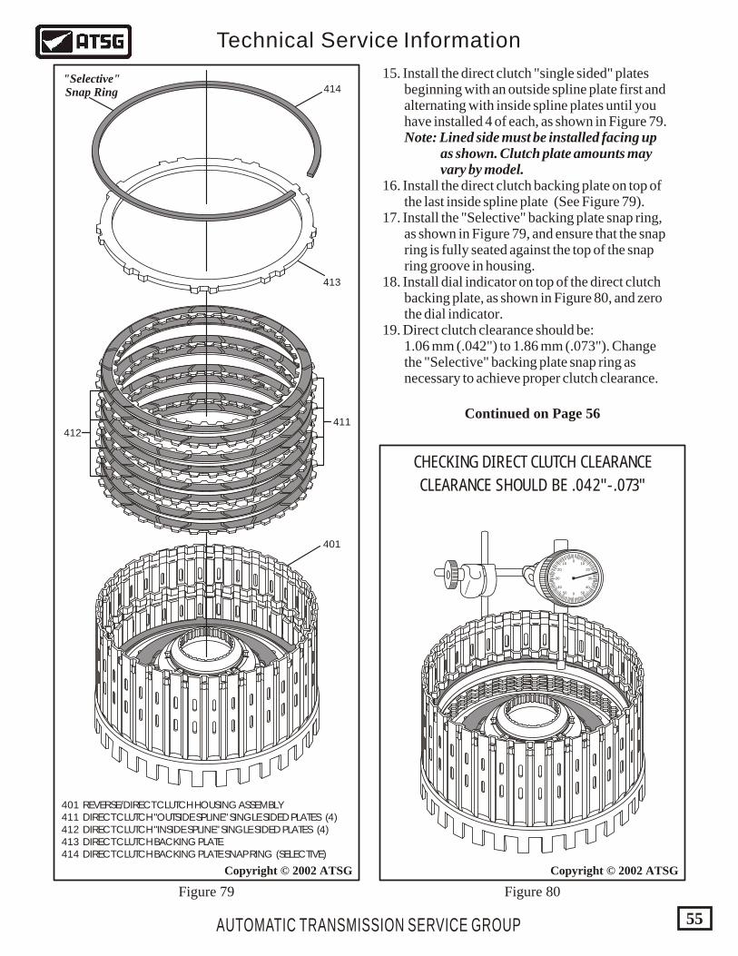
401 REVERSE/DIRECT CLUTCH HOUSING ASSEMBLY 411 DIRECT CLUTCH "OUTSIDE SPLINE" SINGLE SIDED PLATES (4) 412 DIRECT CLUTCH "INSIDE SPLINE" SINGLE SIDED PLATES (4) 413 DIRECT CLUTCH BACKING PLATE 414 DIRECT CLUTCH BACKING PLATE SNAP RING (SELECTIVE)
AUTOMATIC TRANSMISSION SERVICE GROUP
Technical Service Information
55
Copyright © 2002 ATSGCopyright © 2002 ATSG
401
411
413
414
412
"Selective"Snap Ring
0
0
1010
5050
2020
4040
3030
CHECKING DIRECT CLUTCH CLEARANCE
CLEARANCE SHOULD BE .042"-.073"
Figure 80Figure 79
15. Install the direct clutch "single sided" plates beginning with an outside spline plate first and alternating with inside spline plates until you have installed 4 of each, as shown in Figure 79. Note: Lined side must be installed facing up as shown. Clutch plate amounts may vary by model. 16. Install the direct clutch backing plate on top of the last inside spline plate (See Figure 79). 17. Install the "Selective" backing plate snap ring, as shown in Figure 79, and ensure that the snap ring is fully seated against the top of the snap ring groove in housing. 18. Install dial indicator on top of the direct clutch backing plate, as shown in Figure 80, and zero the dial indicator. 19. Direct clutch clearance should be: 1.06 mm (.042") to 1.86 mm (.073"). Change the "Selective" backing plate snap ring as necessary to achieve proper clutch clearance.
Continued on Page 56
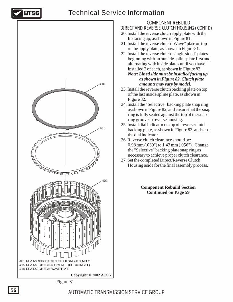
AUTOMATIC TRANSMISSION SERVICE GROUP
Technical Service Information
56
401 REVERSE/DIRECT CLUTCH HOUSING ASSEMBLY 415 REVERSE CLUTCH APPLY PLATE (LIP FACING UP) 416 REVERSE CLUTCH "WAVE" PLATE
Copyright © 2002 ATSG
401
415
416
COMPONENT REBUILDDIRECT AND REVERSE CLUTCH HOUSING (CONT'D) 20. Install the reverse clutch apply plate with the lip facing up, as shown in Figure 81. 21. Install the reverse clutch "Wave" plate on top of the apply plate, as shown in Figure 81. 22. Install the reverse clutch "single sided" plates beginning with an outside spline plate first and alternating with inside plates until you have installed 2 of each, as shown in Figure 82. Note: Lined side must be installed facing up as shown in Figure 82. Clutch plate amounts may vary by model. 23. Install the reverse clutch backing plate on top of the last inside spline plate, as shown in Figure 82. 24. Install the "Selective" backing plate snap ring as shown in Figure 82, and ensure that the snap ring is fully seated against the top of the snap ring groove in reverse housing. 25. Install dial indicator on top of reverse clutch backing plate, as shown in Figure 83, and zero the dial indicator. 26. Reverse clutch clearance should be: 0.98 mm (.039") to 1.43 mm (.056"). Change the "Selective" backing plate snap ring as necessary to achieve proper clutch clearance. 27. Set the completed Direct/Reverse Clutch Housing aside for the final assembly process.
Figure 81
Component Rebuild SectionContinued on Page 59
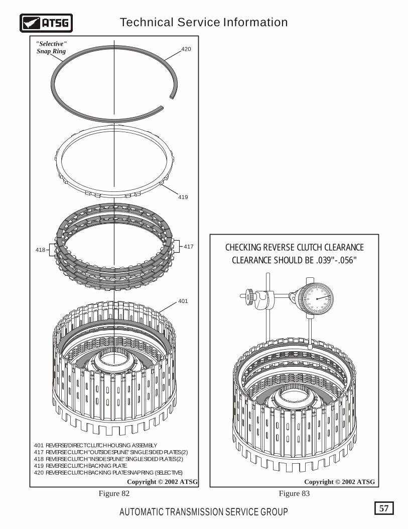
AUTOMATIC TRANSMISSION SERVICE GROUP
Technical Service Information
57
Copyright © 2002 ATSG
0
0
1010
5050
2020
4040
3030
CHECKING REVERSE CLUTCH CLEARANCE
CLEARANCE SHOULD BE .039"-.056"
417
419
420
418
401 REVERSE/DIRECT CLUTCH HOUSING ASSEMBLY 417 REVERSE CLUTCH "OUTSIDE SPLINE" SINGLE SIDED PLATES (2) 418 REVERSE CLUTCH "INSIDE SPLINE" SINGLE SIDED PLATES (2) 419 REVERSE CLUTCH BACKNIG PLATE 420 REVERSE CLUTCH BACKING PLATE SNAP RING (SELECTIVE)
Copyright © 2002 ATSG
401
"Selective"Snap Ring
Figure 83Figure 82
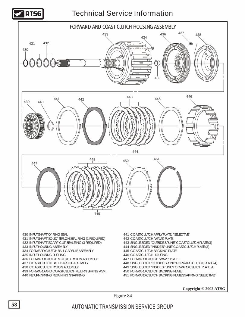
AUTOMATIC TRANSMISSION SERVICE GROUP
Technical Service Information
58
Copyright © 2002 ATSG
FORWARD AND COAST CLUTCH HOUSING ASSEMBLY
430 INPUT SHAFT "O" RING SEAL 431 INPUT SHAFT "SOLID" TEFLON SEAL RING (1 REQUIRED) 432 INPUT SHAFT "SCARF-CUT" SEAL RING (3 REQUIRED) 433 INPUT HOUSING ASSEMBLY 434 FORWARD CLUTCH BALL CAPSULE ASSEMBLY 435 INPUT HOUSING BUSHING 436 FORWARD CLUTCH MOLDED PISTON ASSEMBLY 437 COAST CLUTCH BALL CAPSULE ASSEMBLY 438 COAST CLUTCH PISTON ASSEMBLY 439 FORWARD AND COAST CLUTCH RETURN SPRING ASM. 440 RETURN SPRING RETAINING SNAP RING
441 COAST CLUTCH APPLY PLATE, "SELECTIVE" 442 COAST CLUTCH "WAVE" PLATE 443 SINGLE SIDED "OUTSIDE SPLINE" COAST CLUTCH PLATE (3) 444 SINGLE SIDED "INSIDE SPLINE" COAST CLUTCH PLATE (3) 445 COAST CLUTCH BACKING PLATE 446 COAST CLUTCH HOUSING 447 FORWARD CLUTCH "WAVE" PLATE 448 SINGLE SIDED "OUTSIDE SPLINE" FORWARD CLUTCH PLATE (4) 449 SINGLE SIDED "INSIDE SPLINE" FORWARD CLUTCH PLATE (4) 450 FORWARD CLUTCH BACKING PLATE 451 FORWARD CLUTCH BACKING PLATE SNAP RING "SELECTIVE"
430
431 432
433434
437438
439 440441 442
443
444
445446
447448 450
451
449
435
436
Figure 84
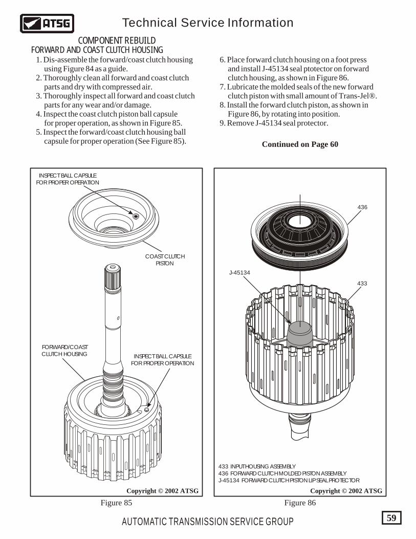
AUTOMATIC TRANSMISSION SERVICE GROUP
Technical Service Information
59
Copyright © 2002 ATSG
433 INPUT HOUSING ASSEMBLY 436 FORWARD CLUTCH MOLDED PISTON ASSEMBLY J-45134 FORWARD CLUTCH PISTON LIP SEAL PROTECTOR
Copyright © 2002 ATSG
433
J-45134
436
INSPECT BALL CAPSULEFOR PROPER OPERATION
COAST CLUTCHPISTON
FORWARD/COASTCLUTCH HOUSING INSPECT BALL CAPSULE
FOR PROPER OPERATION
COMPONENT REBUILDFORWARD AND COAST CLUTCH HOUSING
Figure 85 Figure 86
1. Dis-assemble the forward/coast clutch housing using Figure 84 as a guide. 2. Thoroughly clean all forward and coast clutch parts and dry with compressed air. 3. Thoroughly inspect all forward and coast clutch parts for any wear and/or damage. 4. Inspect the coast clutch piston ball capsule for proper operation, as shown in Figure 85. 5. Inspect the forward/coast clutch housing ball capsule for proper operation (See Figure 85).
6. Place forward clutch housing on a foot press and install J-45134 seal ptotector on forward clutch housing, as shown in Figure 86. 7. Lubricate the molded seals of the new forward clutch piston with small amount of Trans-Jel®. 8. Install the forward clutch piston, as shown in Figure 86, by rotating into position. 9. Remove J-45134 seal protector.
Continued on Page 60
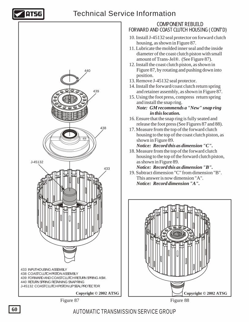
433 INPUT HOUSING ASSEMBLY 438 COAST CLUTCH PISTON ASSEMBLY 439 FORWARD AND COAST CLUTCH RETURN SPRING ASM. 440 RETURN SPRING RETAINING SNAP RING J-45132 COAST CLUTCH PISTON LIP SEAL PROTECTOR
AUTOMATIC TRANSMISSION SERVICE GROUP
Technical Service Information
60
Copyright © 2002 ATSG
433
438
J-45132
439
440
COMPONENT REBUILDFORWARD AND COAST CLUTCH HOUSING (CONT'D)
Figure 87 Figure 88
10. Install J-45132 seal protector on forward clutch housing, as shown in Figure 87. 11. Lubricate the molded inner seal and the inside diameter of the coast clutch piston with small amount of Trans-Jel®. (See Figure 87). 12. Install the coast clutch piston, as shown in Figure 87, by rotating and pushing down into position. 13. Remove J-45132 seal protector. 14. Install the forward/coast clutch return spring and retainer assembly, as shown in Figure 87. 15. Using the foot press, compress return spring and install the snap ring. Note: GM recommends a "New" snap ring in this location. 16. Ensure that the snap ring is fully seated and release the foot press (See Figures 87 and 88). 17. Measure from the top of the forward clutch housing to the top of the coast clutch piston, as shown in Figure 89. Notice: Record this as dimension "C". 18. Measure from the top of the forward clutch housing to the top of the forward clutch piston, as shown in Figure 89. Notice: Record this as dimension "B". 19. Subtract dimension "C" from dimension "B". This answer is now dimension "A". Notice: Record dimension "A".
Copyright © 2002 ATSG
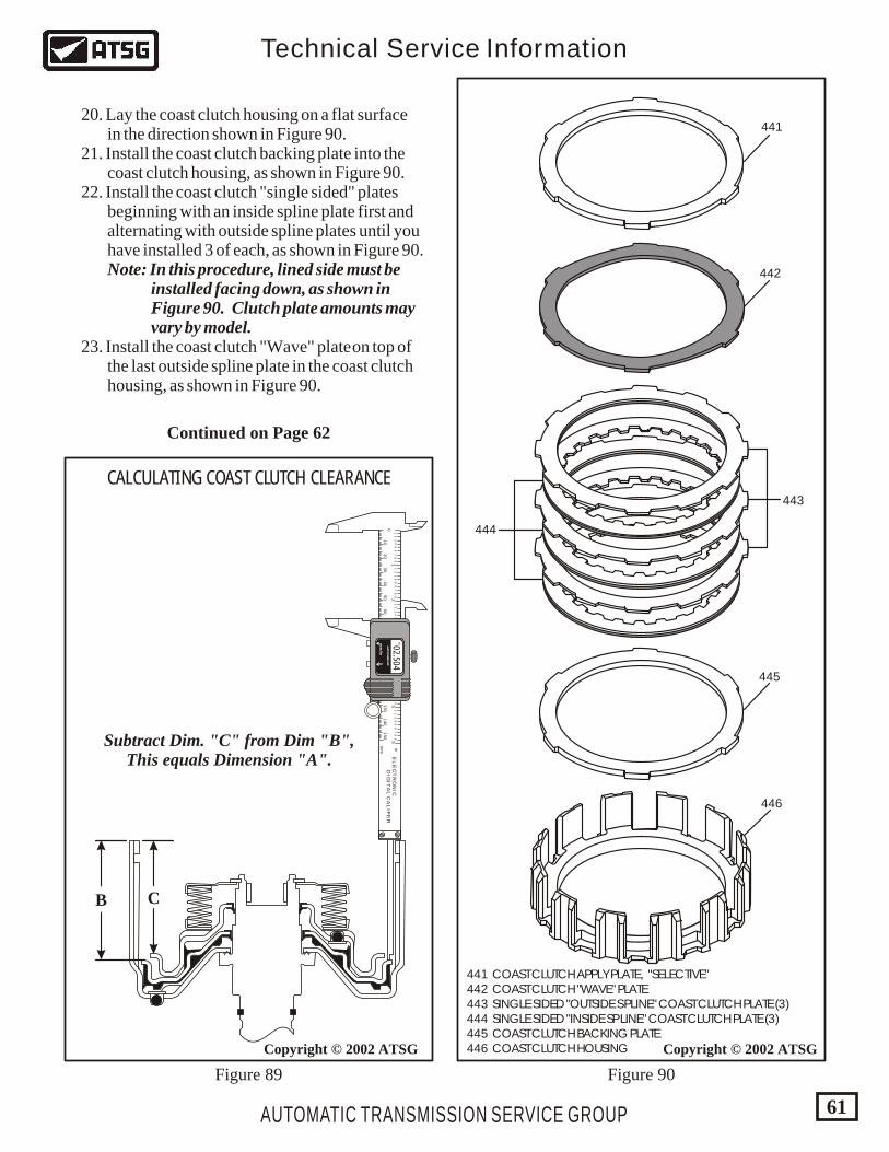
441 COAST CLUTCH APPLY PLATE, "SELECTIVE" 442 COAST CLUTCH "WAVE" PLATE 443 SINGLE SIDED "OUTSIDE SPLINE" COAST CLUTCH PLATE (3) 444 SINGLE SIDED "INSIDE SPLINE" COAST CLUTCH PLATE (3) 445 COAST CLUTCH BACKING PLATE 446 COAST CLUTCH HOUSING
AUTOMATIC TRANSMISSION SERVICE GROUP
Technical Service Information
61
Copyright © 2002 ATSGCopyright © 2002 ATSG
441
442
444
443
445
446
Figure 89 Figure 90
B C
20. Lay the coast clutch housing on a flat surface in the direction shown in Figure 90. 21. Install the coast clutch backing plate into the coast clutch housing, as shown in Figure 90. 22. Install the coast clutch "single sided" plates beginning with an inside spline plate first and alternating with outside spline plates until you have installed 3 of each, as shown in Figure 90. Note: In this procedure, lined side must be installed facing down, as shown in Figure 90. Clutch plate amounts may vary by model. 23. Install the coast clutch "Wave" plate on top of the last outside spline plate in the coast clutch housing, as shown in Figure 90.
Continued on Page 62
43
21
12
34
56
78
91
23
45
67
89
12
34
56
78
91
23
45
67
89
12
34
56
78
91
23
45
67
89
56
10
20
30
40
50
60
70
80
90
150
140
130
120
110
100
0
in
mm
EL
EC
TR
ON
ICD
IGIT
AL
CA
LIP
ER
AU
TO P
OW
ER
-OFF
AU
TO P
OW
ER
-OFF
mm
/inm
m/in
00
02.504IN
CALCULATING COAST CLUTCH CLEARANCE
Subtract Dim. "C" from Dim "B",This equals Dimension "A".
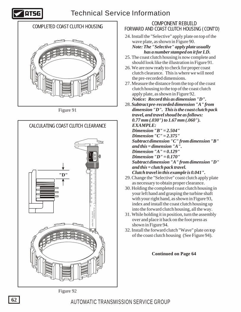
AUTOMATIC TRANSMISSION SERVICE GROUP
Technical Service Information
62
COMPONENT REBUILDFORWARD AND COAST CLUTCH HOUSING (CONT'D)
Figure 92
Figure 91
COMPLETED COAST CLUTCH HOUSING
24. Install the "Selective" apply plate on top of the wave plate, as shown in Figure 90. Note: The "Selective" apply plate usually has a number stamped on it for I.D. 25. The coast clutch housing is now complete and should look like the illustration in Figure 91. 26. We are now ready to check for proper coast clutch clearance. This is where we will need the pre-recorded dimensions. 27. Measure the distance from the top of the coast clutch housing to the top of the coast clutch apply plate, as shown in Figure 92. Notice: Record this as dimension "D". 28. Subtract pre-recorded dimension "A" from dimension "D". This is the coast clutch pack travel, and travel shoud be as follows: 0.77 mm (.030") to 1.67 mm (.060"). EXAMPLE: Dimension "B" = 2.504" Dimension "C" = 2.375" Subtract dimension "C" from dimension "B" and this = dimension "A". Dimension "A" = 0.129" Dimension "D" = 0.170" Subtract dimension "A" from dimension "D" and this = clutch pack travel. Clutch travel in this example is 0.041". 29. Change the "Selective" coast clutch apply plate as necessary to obtain proper clearance. 30. Holding the completed coast clutch housing in your left hand and grasping the turbine shaft with your right hand, as shown in Figure 93, index and install the coast clutch housing up into the forward clutch housing, all the way. 31. While holding it in position, turn the assembly over and place it back on the foot press as shown in Figure 94. 32. Install the forward clutch "Wave" plate on top of the coast clutch housing (See Figure 94).
43
21
12
34
56
78
91
23
45
67
89
12
34
56
78
91
23
45
67
89
12
34
56
78
91
23
45
67
89
56
10
20
30
40
50
60
70
80
90
150
140
130
12
0110
100
0
in
mm
EL
EC
TR
ON
ICD
IGIT
AL
CA
LIP
ER
AU
TO P
OW
ER
-OFF
AU
TO P
OW
ER
-OFF
mm
/inm
m/in
00
00.170IN
"D"
CALCULATING COAST CLUTCH CLEARANCE
Continued on Page 64
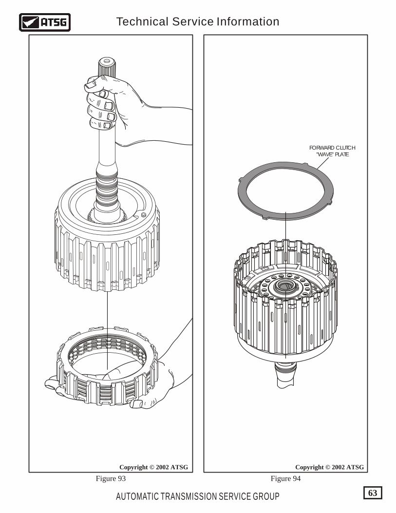
AUTOMATIC TRANSMISSION SERVICE GROUP
Technical Service Information
63
1.1.1
FL
842
FORWARD CLUTCH"WAVE" PLATE
Copyright © 2002 ATSGCopyright © 2002 ATSG
Figure 93 Figure 94
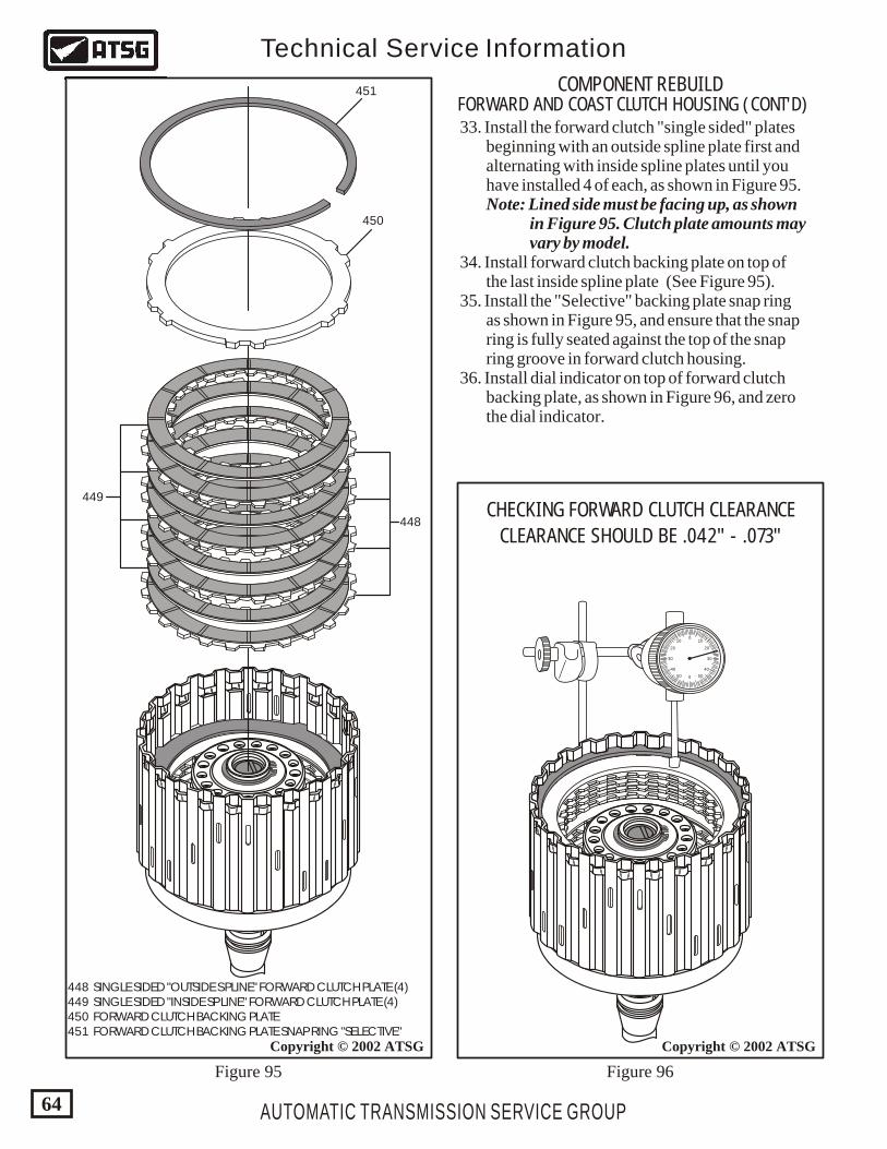
448
450
449
1.1.1
FL842
448 SINGLE SIDED "OUTSIDE SPLINE" FORWARD CLUTCH PLATE (4) 449 SINGLE SIDED "INSIDE SPLINE" FORWARD CLUTCH PLATE (4) 450 FORWARD CLUTCH BACKING PLATE 451 FORWARD CLUTCH BACKING PLATE SNAP RING "SELECTIVE"
451
AUTOMATIC TRANSMISSION SERVICE GROUP
Technical Service Information
64
Copyright © 2002 ATSG Copyright © 2002 ATSG
1.1.1
FL
842
0
0
1010
5050
2020
4040
3030
CHECKING FORWARD CLUTCH CLEARANCE
COMPONENT REBUILDFORWARD AND COAST CLUTCH HOUSING (CONT'D)
CLEARANCE SHOULD BE .042" - .073"
33. Install the forward clutch "single sided" plates beginning with an outside spline plate first and alternating with inside spline plates until you have installed 4 of each, as shown in Figure 95. Note: Lined side must be facing up, as shown in Figure 95. Clutch plate amounts may vary by model. 34. Install forward clutch backing plate on top of the last inside spline plate (See Figure 95). 35. Install the "Selective" backing plate snap ring as shown in Figure 95, and ensure that the snap ring is fully seated against the top of the snap ring groove in forward clutch housing. 36. Install dial indicator on top of forward clutch backing plate, as shown in Figure 96, and zero the dial indicator.
Figure 95 Figure 96
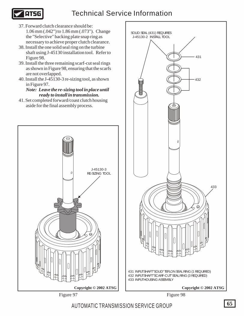
AUTOMATIC TRANSMISSION SERVICE GROUP
Technical Service Information
65
Copyright © 2002 ATSG
431 INPUT SHAFT "SOLID" TEFLON SEAL RING (1 REQUIRED) 432 INPUT SHAFT "SCARF-CUT" SEAL RING (3 REQUIRED) 433 INPUT HOUSING ASSEMBLY
431
SOLID SEAL (431) REQUIRESJ-45130-2 INSTALL TOOL
J-45130-3RE-SIZING TOOL
432
433
37. Forward clutch clearance should be: 1.06 mm (.042") to 1.86 mm (.073"). Change the "Selective" backing plate snap ring as necessary to achieve proper clutch clearance. 38. Install the one solid seal ring on the turbine shaft using J-45130 installation tool. Refer to Figure 98. 39. Install the three remaining scarf-cut seal rings as shown in Figure 98, ensuring that the scarfs are not overlapped. 40. Install the J-45130-3 re-sizing tool, as shown in Figure 97. Note: Leave the re-sizing tool in place until ready to install in transmission. 41. Set completed forward/coast clutch housing aside for the final assembly process.
Figure 98Figure 97
Copyright © 2002 ATSG
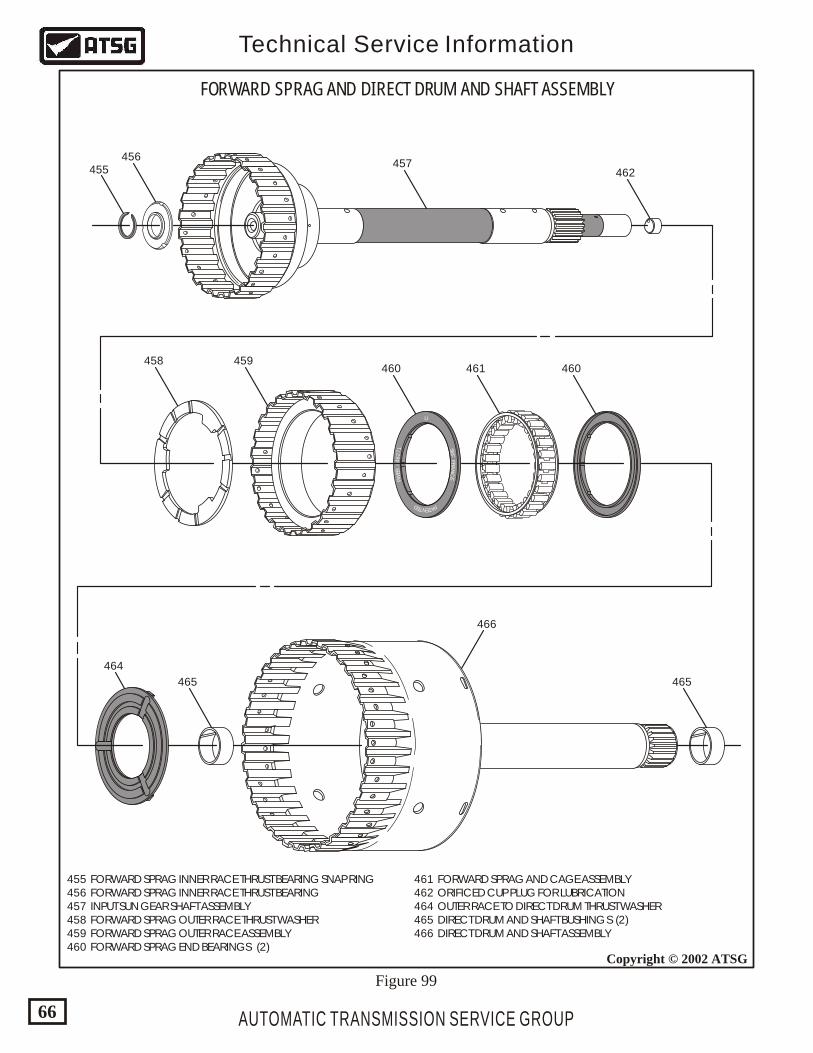
U
ENT TE AD P
FR
AN
FC
EKS
446
EB
27
W1
F
AUTOMATIC TRANSMISSION SERVICE GROUP
Technical Service Information
66
FORWARD SPRAG AND DIRECT DRUM AND SHAFT ASSEMBLY
455456
457
458 459460 460
465 465
466
464
461
462
Copyright © 2002 ATSG
455 FORWARD SPRAG INNER RACE THRUST BEARING SNAP RING 456 FORWARD SPRAG INNER RACE THRUST BEARING 457 INPUT SUN GEAR SHAFT ASSEMBLY 458 FORWARD SPRAG OUTER RACE THRUST WASHER 459 FORWARD SPRAG OUTER RACE ASSEMBLY 460 FORWARD SPRAG END BEARINGS (2)
461 FORWARD SPRAG AND CAGE ASSEMBLY 462 ORIFICED CUP PLUG FOR LUBRICATION 464 OUTER RACE TO DIRECT DRUM THRUST WASHER 465 DIRECT DRUM AND SHAFT BUSHINGS (2) 466 DIRECT DRUM AND SHAFT ASSEMBLY
Figure 99
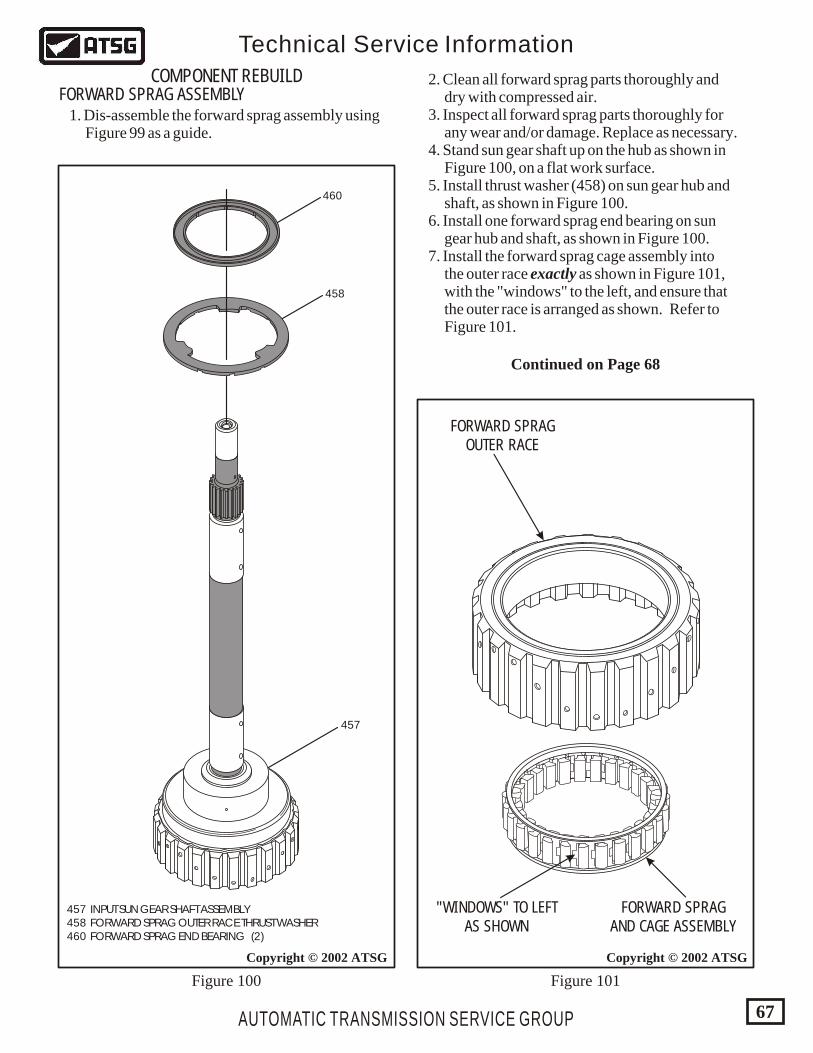
AUTOMATIC TRANSMISSION SERVICE GROUP
Technical Service Information
67
Copyright © 2002 ATSGCopyright © 2002 ATSG
FORWARD SPRAGOUTER RACE
FORWARD SPRAGAND CAGE ASSEMBLY
"WINDOWS" TO LEFTAS SHOWN
457
458
460
457 INPUT SUN GEAR SHAFT ASSEMBLY 458 FORWARD SPRAG OUTER RACE THRUST WASHER 460 FORWARD SPRAG END BEARING (2)
Figure 100 Figure 101
COMPONENT REBUILDFORWARD SPRAG ASSEMBLY 1. Dis-assemble the forward sprag assembly using Figure 99 as a guide.
2. Clean all forward sprag parts thoroughly and dry with compressed air. 3. Inspect all forward sprag parts thoroughly for any wear and/or damage. Replace as necessary. 4. Stand sun gear shaft up on the hub as shown in Figure 100, on a flat work surface. 5. Install thrust washer (458) on sun gear hub and shaft, as shown in Figure 100. 6. Install one forward sprag end bearing on sun gear hub and shaft, as shown in Figure 100. 7. Install the forward sprag cage assembly into the outer race exactly as shown in Figure 101, with the "windows" to the left, and ensure that the outer race is arranged as shown. Refer to Figure 101.
Continued on Page 68
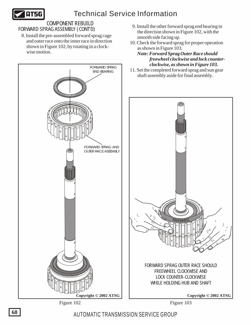
U
ENT
TE
AD
P
FRAN FCE KS
446EB 27W 1F
U
ENT
TE
AD
P
FRAN FCE KS
446EB 27W 1F
F LR EEE EWH
FORWARD SPRAG OUTER RACE SHOULDFREEWHEEL CLOCKWISE ANDLOCK COUNTER-CLOCKWISE
WHILE HOLDING HUB AND SHAFT
AUTOMATIC TRANSMISSION SERVICE GROUP
Technical Service Information
68
Copyright © 2002 ATSGCopyright © 2002 ATSG
FORWARD SPRAG ANDOUTER RACE ASSEMBLY
FORWARD SPRAGEND BEARING
Figure 102 Figure 103
COMPONENT REBUILDFORWARD SPRAG ASSEMBLY (CONT'D) 8. Install the pre-assembled forward sprag cage and outer race onto the inner race in direction shown in Figure 102, by rotating in a clock- wise motion.
9. Install the other forward sprag end bearing in the direction shown in Figure 102, with the smooth side facing up. 10. Check the forward sprag for proper operation as shown in Figure 103. Note: Forward Sprag Outer Race should freewheel clockwise and lock counter- clockwise, as shown in Figure 103. 11. Set the completed forward sprag and sun gear shaft assembly aside for final assembly.
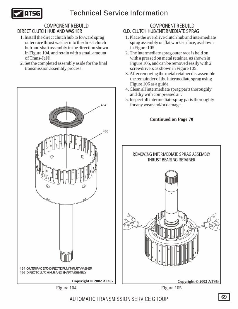
464 OUTER RACE TO DIRECT DRUM THRUST WASHER 466 DIRECT CLUTCH HUB AND SHAFT ASSEMBLY
AUTOMATIC TRANSMISSION SERVICE GROUP
Technical Service Information
69
Copyright © 2002 ATSG
466
464
COMPONENT REBUILD COMPONENT REBUILDDIRECT CLUTCH HUB AND WASHER O.D. CLUTCH HUB/INTERMEDIATE SPRAG 1. Install the direct clutch hub to forward sprag outer race thrust washer into the direct clutch hub and shaft assembly in the direction shown in Figure 104, and retain with a small amount of Trans-Jel®. 2. Set the completed assembly aside for the final transmission assembly process.
1. Place the overdrive clutch hub and intermediate sprag assembly on flat work surface, as shown in Figure 105. 2. The intermediate sprag outer race is held on with a pressed on metal retainer, as shown in Figure 105, and can be removed easily with 2 screwdrivers as shown in Figure 105. 3. After removing the metal retainer dis-assemble the remainder of the intermediate sprag using Figure 106 as a guide. 4. Clean all intermediate sprag parts thoroughly and dry with compressed air. 5. Inspect all intermediate sprag parts thoroughly for any wear and/or damage.
Figure 104 Figure 105
U
ENT
TE
AD
P
FRAN FCE KS
372644BEWF
Copyright © 2002 ATSG
REMOVING INTERMEDIATE SPRAG ASSEMBLYTHRUST BEARING RETAINER
Continued on Page 70
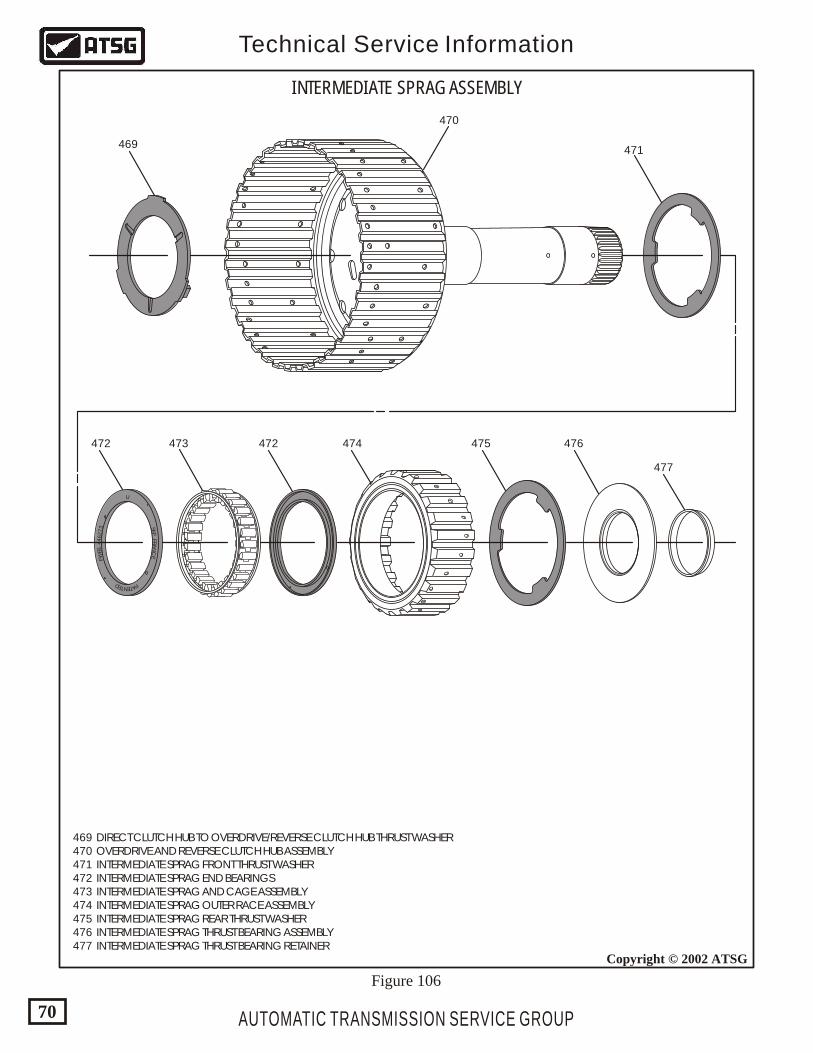
U
ENT TE AD P
F R
AN
FC
EKS
37
26
44
BEW F
AUTOMATIC TRANSMISSION SERVICE GROUP
Technical Service Information
70
Copyright © 2002 ATSG
INTERMEDIATE SPRAG ASSEMBLY
469
470
471
472 472 474 475 476
477
473
469 DIRECT CLUTCH HUB TO OVERDRIVE/REVERSE CLUTCH HUB THRUST WASHER 470 OVERDRIVE AND REVERSE CLUTCH HUB ASSEMBLY 471 INTERMEDIATE SPRAG FRONT THRUST WASHER 472 INTERMEDIATE SPRAG END BEARINGS 473 INTERMEDIATE SPRAG AND CAGE ASSEMBLY 474 INTERMEDIATE SPRAG OUTER RACE ASSEMBLY 475 INTERMEDIATE SPRAG REAR THRUST WASHER 476 INTERMEDIATE SPRAG THRUST BEARING ASSEMBLY 477 INTERMEDIATE SPRAG THRUST BEARING RETAINER
Figure 106
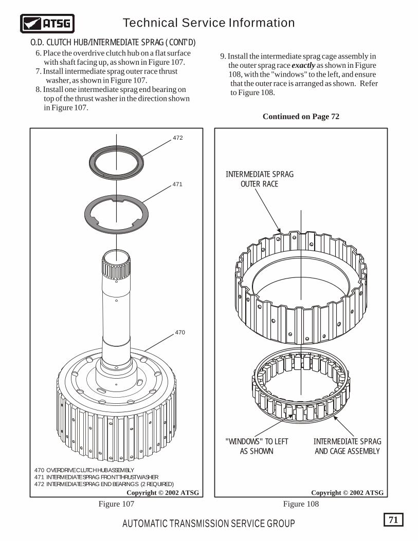
AUTOMATIC TRANSMISSION SERVICE GROUP
Technical Service Information
71
Copyright © 2002 ATSG
470 OVERDRIVE CLUTCH HUB ASSEMBLY 471 INTERMEDIATE SPRAG FRONT THRUST WASHER 472 INTERMEDIATE SPRAG END BEARINGS (2 REQUIRED)
470
471
472
Copyright © 2002 ATSG
INTERMEDIATE SPRAGOUTER RACE
INTERMEDIATE SPRAGAND CAGE ASSEMBLY
"WINDOWS" TO LEFTAS SHOWN
Figure 107 Figure 108
6. Place the overdrive clutch hub on a flat surface with shaft facing up, as shown in Figure 107. 7. Install intermediate sprag outer race thrust washer, as shown in Figure 107. 8. Install one intermediate sprag end bearing on top of the thrust washer in the direction shown in Figure 107.
9. Install the intermediate sprag cage assembly in the outer sprag race exactly as shown in Figure 108, with the "windows" to the left, and ensure that the outer race is arranged as shown. Refer to Figure 108.
Continued on Page 72
O.D. CLUTCH HUB/INTERMEDIATE SPRAG (CONT'D)
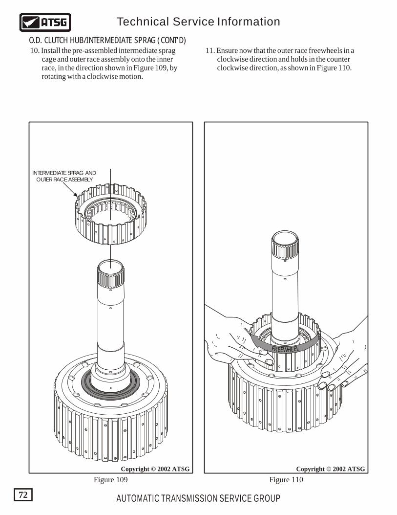
AUTOMATIC TRANSMISSION SERVICE GROUP
Technical Service Information
72
Copyright © 2002 ATSG
INTERMEDIATE SPRAG ANDOUTER RACE ASSEMBLY
Copyright © 2002 ATSG
10. Install the pre-assembled intermediate sprag cage and outer race assembly onto the inner race, in the direction shown in Figure 109, by rotating with a clockwise motion.
11. Ensure now that the outer race freewheels in a clockwise direction and holds in the counter clockwise direction, as shown in Figure 110.
Figure 109 Figure 110
O.D. CLUTCH HUB/INTERMEDIATE SPRAG (CONT'D)
F LR EEE EWH
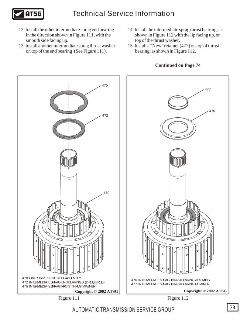
470 OVERDRIVE CLUTCH HUB ASSEMBLY 472 INTERMEDIATE SPRAG END BEARINGS (2 REQUIRED) 475 INTERMEDIATE SPRAG FRONT THRUST WASHER
U
ENT
TE
AD
P
FRAN FCE KS
372644BEWF
AUTOMATIC TRANSMISSION SERVICE GROUP
Technical Service Information
73
Copyright © 2002 ATSG
470
475
472
Copyright © 2002 ATSG
U
ENT
TE
AD
P
FRAN FCE KS
372644BEWF
476 INTERMEDIATE SPRAG THRUST BEARING ASSEMBLY 477 INTERMEDIATE SPRAG THRUST BEARING RETAINER
477
476
Figure 112Figure 111
12. Install the other intermediate sprag end bearing in the direction shown in Figure 111, with the smooth side facing up. 13. Install another intermediate sprag thrust washer on top of the end bearing (See Figure 111).
14. Install the intermediate sprag thrust bearing, as shown in Figure 112 with the lip facing up, on top of the thrust washer. 15. Install a "New" retainer (477) on top of thrust bearing, as shown in Figure 112.
Continued on Page 74
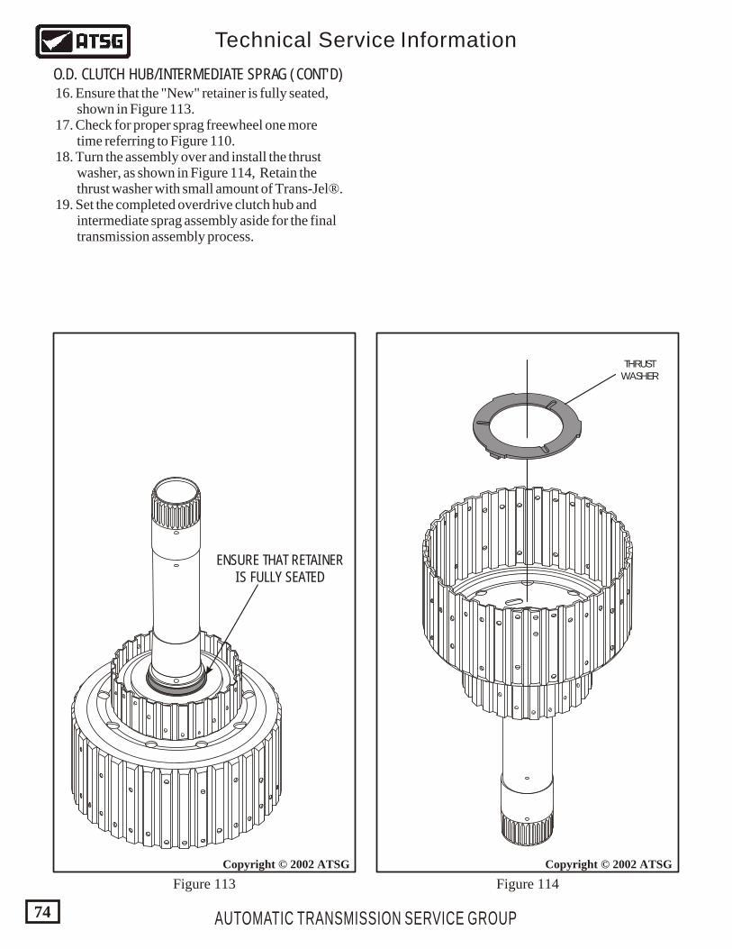
U
ENT
TE
AD
P
FRAN FCE KS
372644BEWF
AUTOMATIC TRANSMISSION SERVICE GROUP
Technical Service Information
74
Copyright © 2002 ATSG
ENSURE THAT RETAINERIS FULLY SEATED
Copyright © 2002 ATSG
THRUSTWASHER
O.D. CLUTCH HUB/INTERMEDIATE SPRAG (CONT'D) 16. Ensure that the "New" retainer is fully seated, shown in Figure 113. 17. Check for proper sprag freewheel one more time referring to Figure 110. 18. Turn the assembly over and install the thrust washer, as shown in Figure 114, Retain the thrust washer with small amount of Trans-Jel®. 19. Set the completed overdrive clutch hub and intermediate sprag assembly aside for the final transmission assembly process.
Figure 113 Figure 114
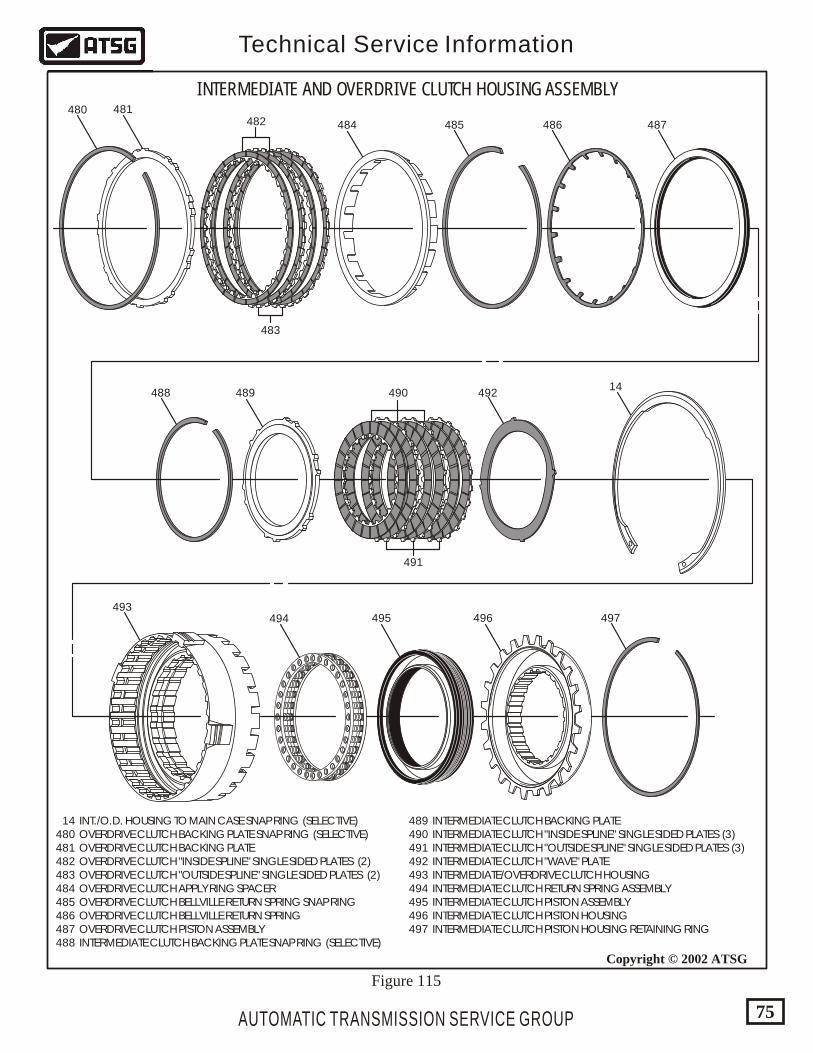
14 INT./O.D. HOUSING TO MAIN CASE SNAP RING (SELECTIVE) 480 OVERDRIVE CLUTCH BACKING PLATE SNAP RING (SELECTIVE) 481 OVERDRIVE CLUTCH BACKING PLATE 482 OVERDRIVE CLUTCH "INSIDE SPLINE" SINGLE SIDED PLATES (2) 483 OVERDRIVE CLUTCH "OUTSIDE SPLINE" SINGLE SIDED PLATES (2) 484 OVERDRIVE CLUTCH APPLY RING SPACER 485 OVERDRIVE CLUTCH BELLVILLE RETURN SPRING SNAP RING 486 OVERDRIVE CLUTCH BELLVILLE RETURN SPRING 487 OVERDRIVE CLUTCH PISTON ASSEMBLY 488 INTERMEDIATE CLUTCH BACKING PLATE SNAP RING (SELECTIVE)
489 INTERMEDIATE CLUTCH BACKING PLATE 490 INTERMEDIATE CLUTCH "INSIDE SPLINE" SINGLE SIDED PLATES (3) 491 INTERMEDIATE CLUTCH "OUTSIDE SPLINE" SINGLE SIDED PLATES (3) 492 INTERMEDIATE CLUTCH "WAVE" PLATE 493 INTERMEDIATE/OVERDRIVE CLUTCH HOUSING 494 INTERMEDIATE CLUTCH RETURN SPRING ASSEMBLY 495 INTERMEDIATE CLUTCH PISTON ASSEMBLY 496 INTERMEDIATE CLUTCH PISTON HOUSING 497 INTERMEDIATE CLUTCH PISTON HOUSING RETAINING RING
INTERMEDIATE AND OVERDRIVE CLUTCH HOUSING ASSEMBLY480 481
482 484 485 486 487
488 489 490 49214
493494 495 496 497
491
483
AUTOMATIC TRANSMISSION SERVICE GROUP
Technical Service Information
75
Copyright © 2002 ATSG
Figure 115
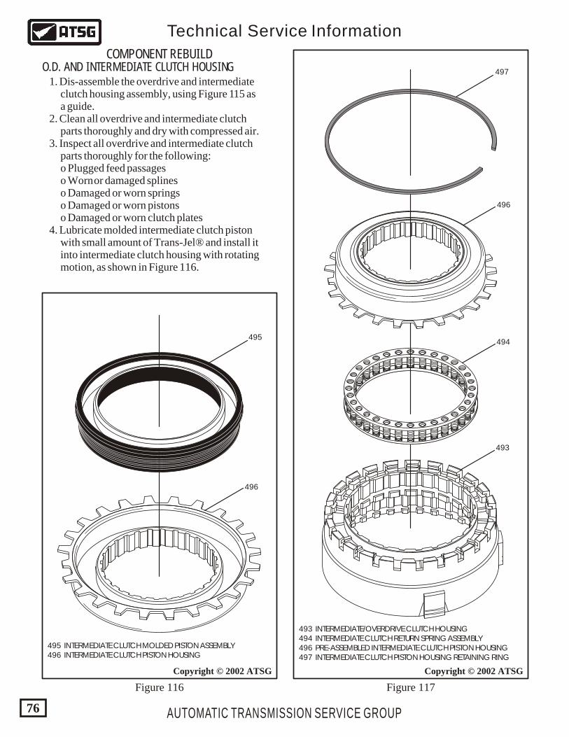
AUTOMATIC TRANSMISSION SERVICE GROUP
Technical Service Information
76
Copyright © 2002 ATSGCopyright © 2002 ATSG
495
496
497
496
494
493
495 INTERMEDIATE CLUTCH MOLDED PISTON ASSEMBLY 496 INTERMEDIATE CLUTCH PISTON HOUSING
493 INTERMEDIATE/OVERDRIVE CLUTCH HOUSING 494 INTERMEDIATE CLUTCH RETURN SPRING ASSEMBLY 496 PRE-ASSEMBLED INTERMEDIATE CLUTCH PISTON HOUSING 497 INTERMEDIATE CLUTCH PISTON HOUSING RETAINING RING
COMPONENT REBUILDO.D. AND INTERMEDIATE CLUTCH HOUSING 1. Dis-assemble the overdrive and intermediate clutch housing assembly, using Figure 115 as a guide. 2. Clean all overdrive and intermediate clutch parts thoroughly and dry with compressed air. 3. Inspect all overdrive and intermediate clutch parts thoroughly for the following: o Plugged feed passages o Worn or damaged splines o Damaged or worn springs o Damaged or worn pistons o Damaged or worn clutch plates 4. Lubricate molded intermediate clutch piston with small amount of Trans-Jel® and install it into intermediate clutch housing with rotating motion, as shown in Figure 116.
Figure 116 Figure 117
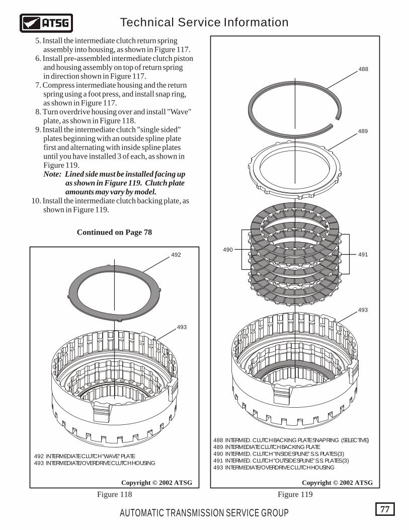
AUTOMATIC TRANSMISSION SERVICE GROUP
Technical Service Information
77
Copyright © 2002 ATSG Copyright © 2002 ATSG
492 491490
489
488
493
493
492 INTERMEDIATE CLUTCH "WAVE" PLATE 493 INTERMEDIATE/OVERDRIVE CLUTCH HOUSING
488 INTERMED. CLUTCH BACKING PLATE SNAP RING (SELECTIVE) 489 INTERMEDIATE CLUTCH BACKING PLATE 490 INTERMED. CLUTCH "INSIDE SPLINE" S.S. PLATES (3) 491 INTERMED. CLUTCH "OUTSIDE SPLINE" S.S. PLATES (3) 493 INTERMEDIATE/OVERDRIVE CLUTCH HOUSING
Figure 119Figure 118
5. Install the intermediate clutch return spring assembly into housing, as shown in Figure 117. 6. Install pre-assembled intermediate clutch piston and housing assembly on top of return spring in direction shown in Figure 117. 7. Compress intermediate housing and the return spring using a foot press, and install snap ring, as shown in Figure 117. 8. Turn overdrive housing over and install "Wave" plate, as shown in Figure 118. 9. Install the intermediate clutch "single sided" plates beginning with an outside spline plate first and alternating with inside spline plates until you have installed 3 of each, as shown in Figure 119. Note: Lined side must be installed facing up as shown in Figure 119. Clutch plate amounts may vary by model. 10. Install the intermediate clutch backing plate, as shown in Figure 119.
Continued on Page 78
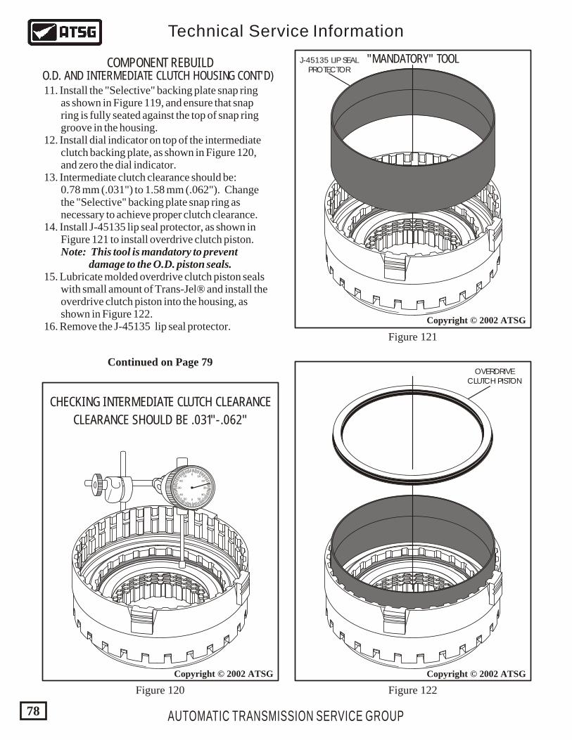
Copyright © 2002 ATSG
Copyright © 2002 ATSG
OVERDRIVECLUTCH PISTON
AUTOMATIC TRANSMISSION SERVICE GROUP
Technical Service Information
78
Copyright © 2002 ATSG
0
0
1010
5050
2020
4040
3030
CHECKING INTERMEDIATE CLUTCH CLEARANCE
CLEARANCE SHOULD BE .031"-.062"
J-45135 LIP SEALPROTECTOR
COMPONENT REBUILDO.D. AND INTERMEDIATE CLUTCH HOUSING CONT'D) 11. Install the "Selective" backing plate snap ring as shown in Figure 119, and ensure that snap ring is fully seated against the top of snap ring groove in the housing. 12. Install dial indicator on top of the intermediate clutch backing plate, as shown in Figure 120, and zero the dial indicator. 13. Intermediate clutch clearance should be: 0.78 mm (.031") to 1.58 mm (.062"). Change the "Selective" backing plate snap ring as necessary to achieve proper clutch clearance. 14. Install J-45135 lip seal protector, as shown in Figure 121 to install overdrive clutch piston. Note: This tool is mandatory to prevent damage to the O.D. piston seals. 15. Lubricate molded overdrive clutch piston seals with small amount of Trans-Jel® and install the overdrive clutch piston into the housing, as shown in Figure 122. 16. Remove the J-45135 lip seal protector.
Figure 120 Figure 122
Figure 121
"MANDATORY" TOOL
Continued on Page 79
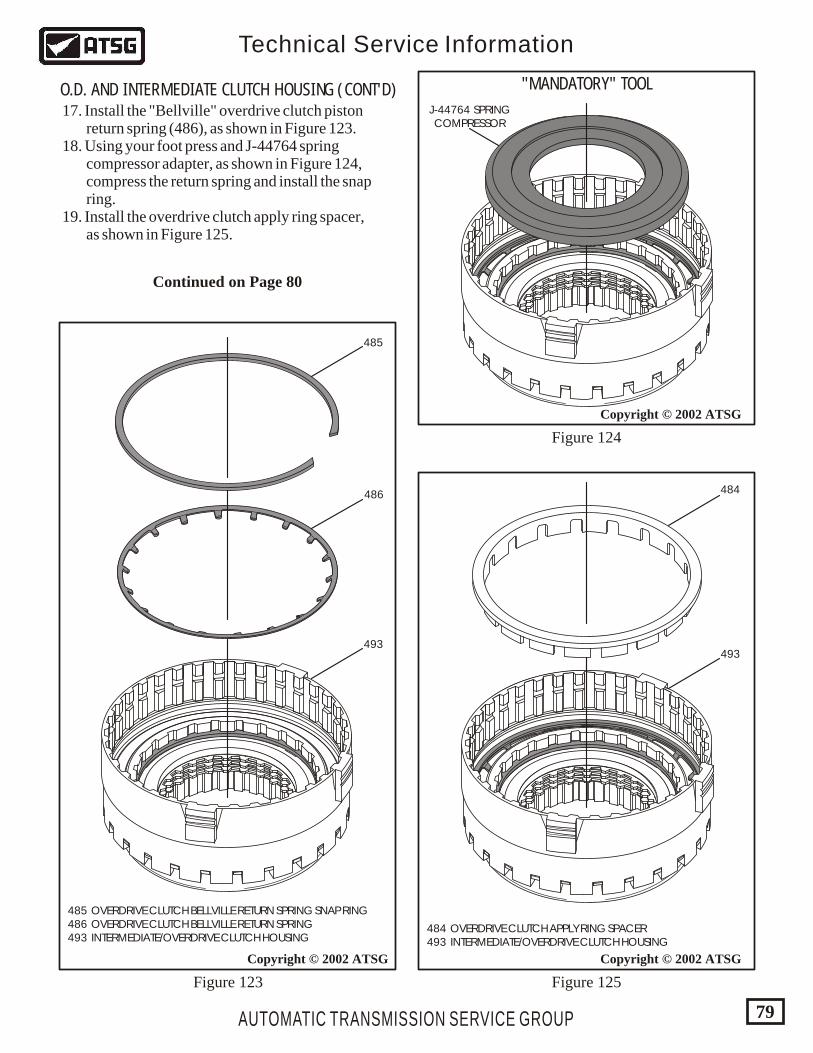
AUTOMATIC TRANSMISSION SERVICE GROUP
Technical Service Information
79
484 OVERDRIVE CLUTCH APPLY RING SPACER 493 INTERMEDIATE/OVERDRIVE CLUTCH HOUSING
Copyright © 2002 ATSG
Copyright © 2002 ATSG
Copyright © 2002 ATSG
485
486
493
485 OVERDRIVE CLUTCH BELLVILLE RETURN SPRING SNAP RING 486 OVERDRIVE CLUTCH BELLVILLE RETURN SPRING 493 INTERMEDIATE/OVERDRIVE CLUTCH HOUSING
Figure 125
Figure 124
Figure 123
O.D. AND INTERMEDIATE CLUTCH HOUSING (CONT'D) 17. Install the "Bellville" overdrive clutch piston return spring (486), as shown in Figure 123. 18. Using your foot press and J-44764 spring compressor adapter, as shown in Figure 124, compress the return spring and install the snap ring. 19. Install the overdrive clutch apply ring spacer, as shown in Figure 125.
484
493
"MANDATORY" TOOL
J-44764 SPRINGCOMPRESSOR
Continued on Page 80
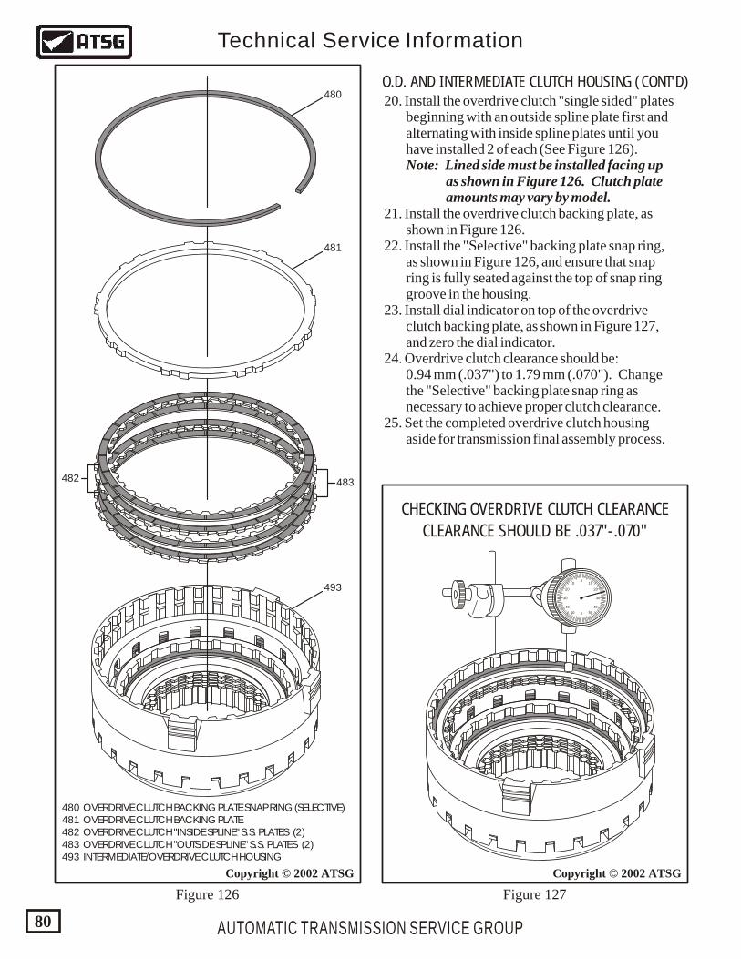
AUTOMATIC TRANSMISSION SERVICE GROUP
Technical Service Information
80
Copyright © 2002 ATSGCopyright © 2002 ATSG
0
0
1010
5050
2020
4040
3030
CHECKING OVERDRIVE CLUTCH CLEARANCE
CLEARANCE SHOULD BE .037"-.070"
480
481
483482
493
480 OVERDRIVE CLUTCH BACKING PLATE SNAP RING (SELECTIVE) 481 OVERDRIVE CLUTCH BACKING PLATE 482 OVERDRIVE CLUTCH "INSIDE SPLINE" S.S. PLATES (2) 483 OVERDRIVE CLUTCH "OUTSIDE SPLINE" S.S. PLATES (2) 493 INTERMEDIATE/OVERDRIVE CLUTCH HOUSING
O.D. AND INTERMEDIATE CLUTCH HOUSING (CONT'D) 20. Install the overdrive clutch "single sided" plates beginning with an outside spline plate first and alternating with inside spline plates until you have installed 2 of each (See Figure 126). Note: Lined side must be installed facing up as shown in Figure 126. Clutch plate amounts may vary by model. 21. Install the overdrive clutch backing plate, as shown in Figure 126. 22. Install the "Selective" backing plate snap ring, as shown in Figure 126, and ensure that snap ring is fully seated against the top of snap ring groove in the housing. 23. Install dial indicator on top of the overdrive clutch backing plate, as shown in Figure 127, and zero the dial indicator. 24. Overdrive clutch clearance should be: 0.94 mm (.037") to 1.79 mm (.070"). Change the "Selective" backing plate snap ring as necessary to achieve proper clutch clearance. 25. Set the completed overdrive clutch housing aside for transmission final assembly process.
Figure 126 Figure 127
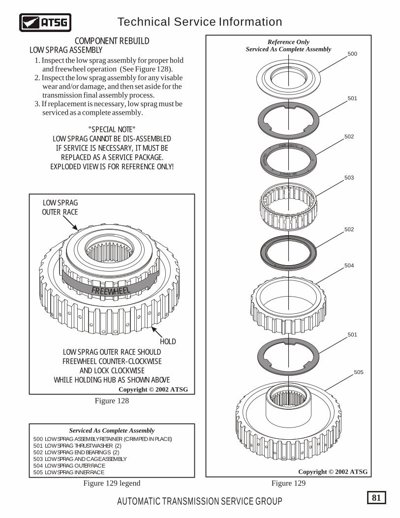
500 LOW SPRAG ASSEMBLY RETAINER (CRIMPED IN PLACE) 501 LOW SPRAG THRUST WASHER (2) 502 LOW SPRAG END BEARINGS (2) 503 LOW SPRAG AND CAGE ASSEMBLY 504 LOW SPRAG OUTER RACE 505 LOW SPRAG INNER RACE
U
ENT
TE
AD
P
FRAN FCE KS
372644BEWF
F LR EEE EWH
AUTOMATIC TRANSMISSION SERVICE GROUP
Technical Service Information
81
Copyright © 2002 ATSG
Copyright © 2002 ATSG
LOW SPRAG OUTER RACE SHOULDFREEWHEEL COUNTER-CLOCKWISE
AND LOCK CLOCKWISEWHILE HOLDING HUB AS SHOWN ABOVE
"SPECIAL NOTE"LOW SPRAG CANNOT BE DIS-ASSEMBLEDIF SERVICE IS NECESSARY, IT MUST BE
REPLACED AS A SERVICE PACKAGE.EXPLODED VIEW IS FOR REFERENCE ONLY!
HOLD
LOW SPRAGOUTER RACE
500
501
501
502
503
504
505
502
Serviced As Complete Assembly
Reference OnlyServiced As Complete AssemblyLOW SPRAG ASSEMBLY
COMPONENT REBUILD
1. Inspect the low sprag assembly for proper hold and freewheel operation (See Figure 128). 2. Inspect the low sprag assembly for any visable wear and/or damage, and then set aside for the transmission final assembly process. 3. If replacement is necessary, low sprag must be serviced as a complete assembly.
Figure 128
Figure 129Figure 129 legend
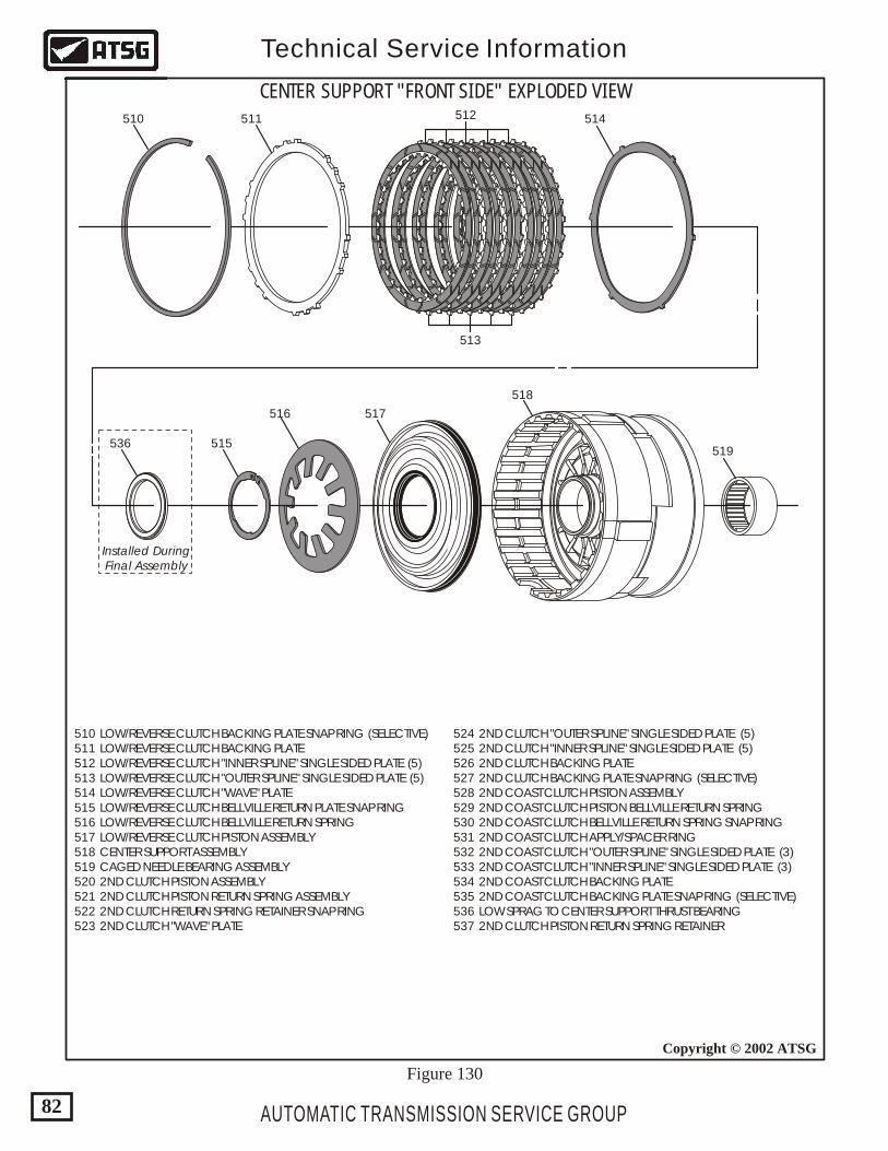
AUTOMATIC TRANSMISSION SERVICE GROUP
Technical Service Information
82
Copyright © 2002 ATSG
CENTER SUPPORT "FRONT SIDE" EXPLODED VIEW510 511 512 514
515536
Installed DuringFinal Assembly
516 517
518
519
513
510 LOW/REVERSE CLUTCH BACKING PLATE SNAP RING (SELECTIVE) 511 LOW/REVERSE CLUTCH BACKING PLATE 512 LOW/REVERSE CLUTCH "INNER SPLINE" SINGLE SIDED PLATE (5) 513 LOW/REVERSE CLUTCH "OUTER SPLINE" SINGLE SIDED PLATE (5) 514 LOW/REVERSE CLUTCH "WAVE" PLATE 515 LOW/REVERSE CLUTCH BELLVILLE RETURN PLATE SNAP RING 516 LOW/REVERSE CLUTCH BELLVILLE RETURN SPRING 517 LOW/REVERSE CLUTCH PISTON ASSEMBLY 518 CENTER SUPPORT ASSEMBLY 519 CAGED NEEDLE BEARING ASSEMBLY 520 2ND CLUTCH PISTON ASSEMBLY 521 2ND CLUTCH PISTON RETURN SPRING ASSEMBLY 522 2ND CLUTCH RETURN SPRING RETAINER SNAP RING 523 2ND CLUTCH "WAVE" PLATE
524 2ND CLUTCH "OUTER SPLINE" SINGLE SIDED PLATE (5) 525 2ND CLUTCH "INNER SPLINE" SINGLE SIDED PLATE (5) 526 2ND CLUTCH BACKING PLATE 527 2ND CLUTCH BACKING PLATE SNAP RING (SELECTIVE) 528 2ND COAST CLUTCH PISTON ASSEMBLY 529 2ND COAST CLUTCH PISTON BELLVILLE RETURN SPRING 530 2ND COAST CLUTCH BELLVILLE RETURN SPRING SNAP RING 531 2ND COAST CLUTCH APPLY/SPACER RING 532 2ND COAST CLUTCH "OUTER SPLINE" SINGLE SIDED PLATE (3) 533 2ND COAST CLUTCH "INNER SPLINE" SINGLE SIDED PLATE (3) 534 2ND COAST CLUTCH BACKING PLATE 535 2ND COAST CLUTCH BACKING PLATE SNAP RING (SELECTIVE) 536 LOW SPRAG TO CENTER SUPPORT THRUST BEARING 537 2ND CLUTCH PISTON RETURN SPRING RETAINER
Figure 130
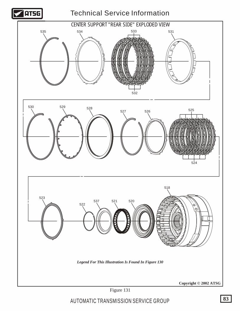
96
02
29
71
99
12
1.1.1
FL
AUTOMATIC TRANSMISSION SERVICE GROUP
Technical Service Information
83
Copyright © 2002 ATSG
CENTER SUPPORT "REAR SIDE" EXPLODED VIEW535 534 531
530 529 528527
523
522537 521 520
518
526 525
524
533
532
Legend For This Illustration Is Found In Figure 130
Figure 131
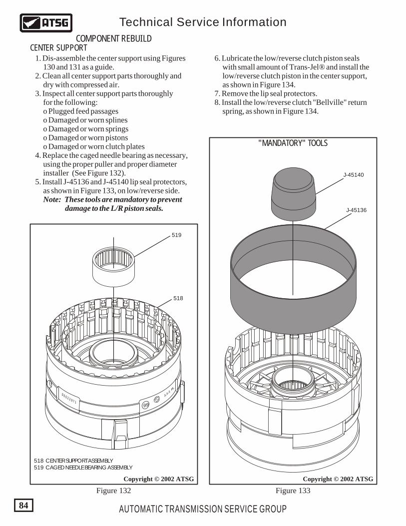
9 6 0 2 2 9 7 1
99
12
1.1.1
FL
AUTOMATIC TRANSMISSION SERVICE GROUP
Technical Service Information
84
Copyright © 2002 ATSGCopyright © 2002 ATSG
519
J-45136
J-45140
518
518 CENTER SUPPORT ASSEMBLY 519 CAGED NEEDLE BEARING ASSEMBLY
COMPONENT REBUILDCENTER SUPPORT
Figure 132 Figure 133
"MANDATORY" TOOLS
1. Dis-assemble the center support using Figures 130 and 131 as a guide. 2. Clean all center support parts thoroughly and dry with compressed air. 3. Inspect all center support parts thoroughly for the following: o Plugged feed passages o Damaged or worn splines o Damaged or worn springs o Damaged or worn pistons o Damaged or worn clutch plates 4. Replace the caged needle bearing as necessary, using the proper puller and proper diameter installer (See Figure 132). 5. Install J-45136 and J-45140 lip seal protectors, as shown in Figure 133, on low/reverse side. Note: These tools are mandatory to prevent damage to the L/R piston seals.
6. Lubricate the low/reverse clutch piston seals with small amount of Trans-Jel® and install the low/reverse clutch piston in the center support, as shown in Figure 134. 7. Remove the lip seal protectors. 8. Install the low/reverse clutch "Bellville" return spring, as shown in Figure 134.
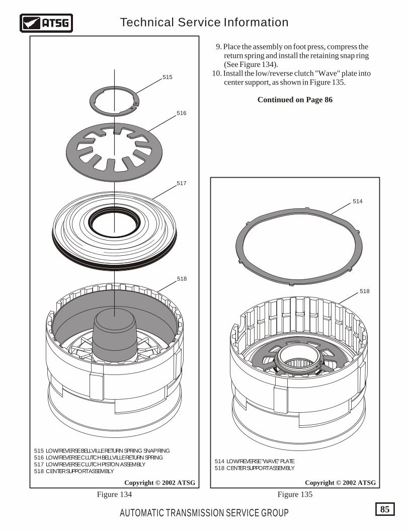
AUTOMATIC TRANSMISSION SERVICE GROUP
Technical Service Information
85
Copyright © 2002 ATSGCopyright © 2002 ATSG
515 LOW/REVERSE BELLVILLE RETURN SPRING SNAP RING 516 LOW/REVERSE CLUTCH BELLVILLE RETURN SPRING 517 LOW/REVERSE CLUTCH PISTON ASSEMBLY 518 CENTER SUPPORT ASSEMBLY
514 LOW/REVERSE "WAVE" PLATE 518 CENTER SUPPORT ASSEMBLY
515
516
517
518
518
514
Figure 134 Figure 135
9. Place the assembly on foot press, compress the return spring and install the retaining snap ring (See Figure 134). 10. Install the low/reverse clutch "Wave" plate into center support, as shown in Figure 135.
Continued on Page 86
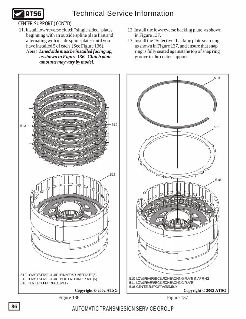
512 LOW/REVERSE CLUTCH "INNER SPLINE" PLATE (5) 513 LOW/REVERSE CLUTCH "OUTER SPLINE" PLATE (5) 518 CENTER SUPPORT ASSEMBLY
510 LOW/REVERSE CLUTCH BACKING PLATE SNAP RING 511 LOW/REVERSE CLUTCH BACKING PLATE 518 CENTER SUPPORT ASSEMBLY
AUTOMATIC TRANSMISSION SERVICE GROUP
Technical Service Information
86
Copyright © 2002 ATSGCopyright © 2002 ATSG
513 512
518
518
511
510
Figure 136 Figure 137
CENTER SUPPORT (CONT'D) 11. Install low/reverse clutch "single sided" plates beginning with an outside spline plate first and alternating with inside spline plates until you have installed 5 of each (See Figure 136). Note: Lined side must be installed facing up, as shown in Figure 136. Clutch plate amounts may vary by model.
12. Install the low/reverse backing plate, as shown in Figure 137. 13. Install the "Selective" backing plate snap ring, as shown in Figure 137, and ensure that snap ring is fully seated against the top of snap ring groove in the center support.
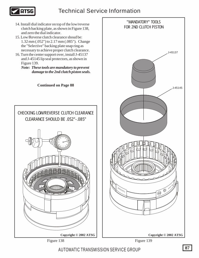
AUTOMATIC TRANSMISSION SERVICE GROUP
Technical Service Information
87
Copyright © 2002 ATSG
0
0
1010
5050
2020
4040
3030
CHECKING LOW/REVERSE CLUTCH CLEARANCE
CLEARANCE SHOULD BE .052"-.085"
Figure 138 Figure 139
Copyright © 2002 ATSG
J-45137
J-45145
9 6 0 2 2 9 7 1
99
12
1.1.1
FL
14. Install dial indicator on top of the low/reverse clutch backing plate, as shown in Figure 138, and zero the dial indicator. 15. Low/Reverse clutch clearance shoud be: 1.32 mm (.052") to 2.17 mm (.085"). Change the "Selective" backing plate snap ring as necessary to achieve proper clutch clearance. 16. Turn the center support over, install J-45137 and J-45145 lip seal protectors, as shown in Figure 139. Note: These tools are mandatory to prevent damage to the 2nd clutch piston seals.
Continued on Page 88
"MANDATORY" TOOLSFOR 2ND CLUTCH PISTON
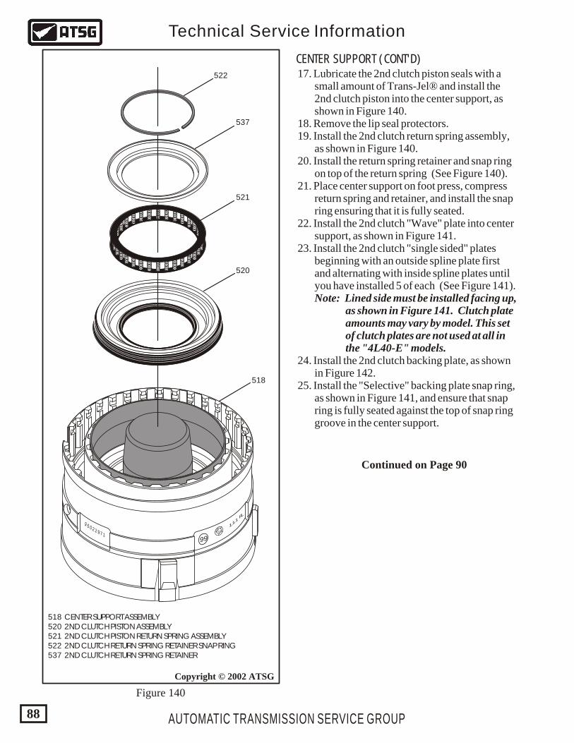
AUTOMATIC TRANSMISSION SERVICE GROUP
Technical Service Information
88
Copyright © 2002 ATSG
9 6 0 2 2 9 7 1
99
12
1.1.1
FL
522
521
537
520
518
518 CENTER SUPPORT ASSEMBLY 520 2ND CLUTCH PISTON ASSEMBLY 521 2ND CLUTCH PISTON RETURN SPRING ASSEMBLY 522 2ND CLUTCH RETURN SPRING RETAINER SNAP RING 537 2ND CLUTCH RETURN SPRING RETAINER
Figure 140
CENTER SUPPORT (CONT'D) 17. Lubricate the 2nd clutch piston seals with a small amount of Trans-Jel® and install the 2nd clutch piston into the center support, as shown in Figure 140. 18. Remove the lip seal protectors. 19. Install the 2nd clutch return spring assembly, as shown in Figure 140. 20. Install the return spring retainer and snap ring on top of the return spring (See Figure 140). 21. Place center support on foot press, compress return spring and retainer, and install the snap ring ensuring that it is fully seated. 22. Install the 2nd clutch "Wave" plate into center support, as shown in Figure 141. 23. Install the 2nd clutch "single sided" plates beginning with an outside spline plate first and alternating with inside spline plates until you have installed 5 of each (See Figure 141). Note: Lined side must be installed facing up, as shown in Figure 141. Clutch plate amounts may vary by model. This set of clutch plates are not used at all in the "4L40-E" models. 24. Install the 2nd clutch backing plate, as shown in Figure 142. 25. Install the "Selective" backing plate snap ring, as shown in Figure 141, and ensure that snap ring is fully seated against the top of snap ring groove in the center support.
Continued on Page 90
AUTOMATIC TRANSMISSION SERVICE GROUP
Technical Service Information
89
Copyright © 2002 ATSGCopyright © 2002 ATSG
9 6 0 2 2 9 7 1
99
12
1.1.1
FL
518518
526
527
523
524525
518 CENTER SUPPORT ASSEMBLY 523 2ND CLUTCH "WAVE" PLATE 524 2ND CLUTCH "OUTER SPLINE" SINGLE SIDED PLATE (5) 525 2ND CLUTCH "INNER SPLINE" SINGLE SIDED PLATE (5)
518 CENTER SUPPORT ASSEMBLY 526 2ND CLUTCH BACKING PLATE 527 2ND CLUTCH BACKING PLATE SNAP RING (SELECTIVE)
9 6 0 2 2 9 7 1
99
12
1.1.1
FL
Figure 141 Figure 142
AUTOMATIC TRANSMISSION SERVICE GROUP
Technical Service Information
90
Copyright © 2002 ATSGCopyright © 2002 ATSG
9 6 0 2 2 9 7 1
99
12
1.1.1
FL
0
0
1010
5050
2020
4040
3030
CHECKING 2ND CLUTCH CLEARANCE
CLEARANCE SHOULD BE .052"-.076"
J-45136
9 6 0 2 2 9 7 1
99
12
1.1.1
FL
CENTER SUPPORT (CONT'D)
"MANDATORY" TOOL
26. Install dial indicator on top of the 2nd clutch backing plate, as shown in Figure 143, and zero the dial indicator. 27. 2nd Clutch clearance should be: 1.32 mm (.052") to 1.92 mm (.076"). Change the "Selective" backing plate snap ring as necessary to achieve proper clutch clearance. 28. Install J-45136 lip seal protector, as shown in Figure 144. Note: This is a mandatory tool to prevent any damage to 2nd coast clutch piston seals. 29. Lubricate the 2nd coast clutch piston seals with small amount of Trans-Jel® and install the 2nd coast clutch piston into the center support using the J-45145 installation tool (See Figure 145).
Figure 143 Figure 144
30. Remove the J-45136 lip seal protector. 31. Install the 2nd coast clutch "Bellville" return spring, as shown in Figure 146. 32. Compress return spring and install the return spring snap ring as shown in Figure 146.
Continued on Page 93
518 CENTER SUPPORT ASSEMBLY 529 2ND COAST CLUTCH PISTON RETURN SPRING 530 2ND COAST CLUTCH RETURN SPRING SNAP RING
518 CENTER SUPPORT ASSEMBLY 528 2ND COAST CLUTCH PISTON ASSEMBLY
AUTOMATIC TRANSMISSION SERVICE GROUP
Technical Service Information
91
Copyright © 2002 ATSGCopyright © 2002 ATSG
9 6 0 2 2 9 7 1
99
12
1.1.1
FL
9 6 0 2 2 9 7 1
99
12
1.1.1
FL
518
518
528
J-45145 PISTONINSTALLER
529
530
Figure 145 Figure 146
518 CENTER SUPPORT ASSEMBLY 531 2ND COAST CLUTCH APPLY RING SPACER 532 2ND COAST CLUTCH "OUTER SPLINE" S.S. PLATES (3) 533 2ND COAST CLUTCH "INNER SPLINE" S.S. PLATES (3)
AUTOMATIC TRANSMISSION SERVICE GROUP
Technical Service Information
92
Copyright © 2002 ATSG
9 6 0 2 2 9 7 1
99
12
1.1.1
FL
518
531
532533
Copyright © 2002 ATSG
518 CENTER SUPPORT ASSEMBLY 534 2ND COAST CLUTCH BACKING PLATE 535 2ND COAST CLUTCH BACKING PLATE SNAP RING (SELECTIVE)
534
518
535
9 6 0 2 2 9 7 1
99
12
1.1.1
FL
Figure 147 Figure 148
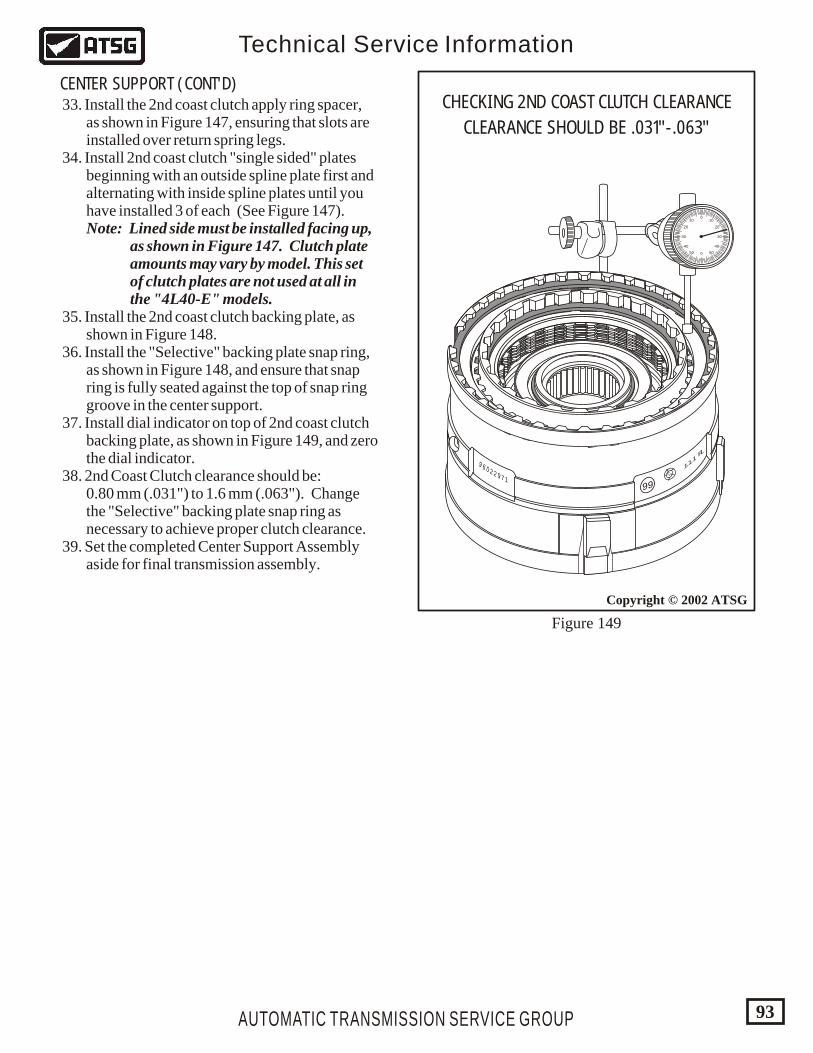
AUTOMATIC TRANSMISSION SERVICE GROUP
Technical Service Information
93
Copyright © 2002 ATSG
9 6 0 2 2 9 7 1
99
12
1.1.1
FL
0
0
1010
5050
2020
4040
3030
CHECKING 2ND COAST CLUTCH CLEARANCE
CLEARANCE SHOULD BE .031"-.063"
Figure 149
CENTER SUPPORT (CONT'D) 33. Install the 2nd coast clutch apply ring spacer, as shown in Figure 147, ensuring that slots are installed over return spring legs. 34. Install 2nd coast clutch "single sided" plates beginning with an outside spline plate first and alternating with inside spline plates until you have installed 3 of each (See Figure 147). Note: Lined side must be installed facing up, as shown in Figure 147. Clutch plate amounts may vary by model. This set of clutch plates are not used at all in the "4L40-E" models. 35. Install the 2nd coast clutch backing plate, as shown in Figure 148. 36. Install the "Selective" backing plate snap ring, as shown in Figure 148, and ensure that snap ring is fully seated against the top of snap ring groove in the center support. 37. Install dial indicator on top of 2nd coast clutch backing plate, as shown in Figure 149, and zero the dial indicator. 38. 2nd Coast Clutch clearance should be: 0.80 mm (.031") to 1.6 mm (.063"). Change the "Selective" backing plate snap ring as necessary to achieve proper clutch clearance. 39. Set the completed Center Support Assembly aside for final transmission assembly.
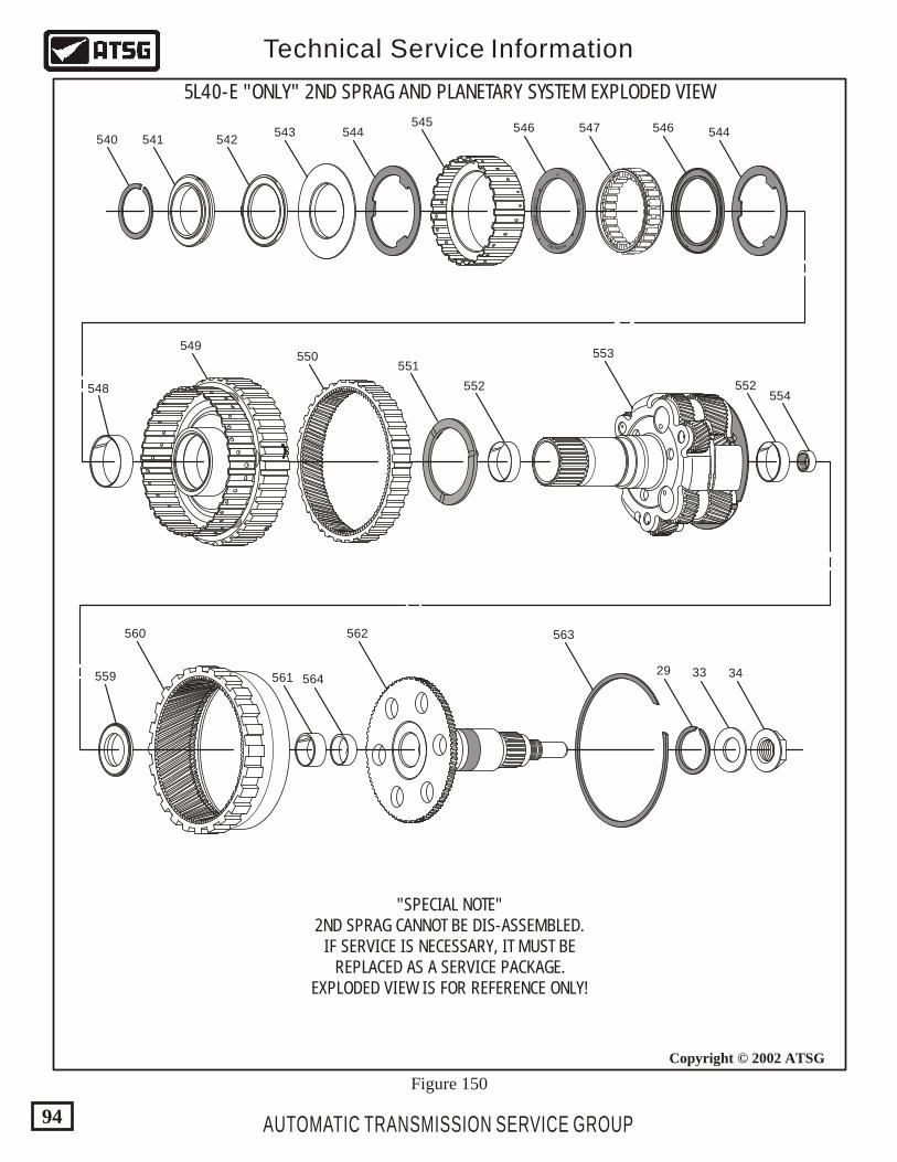
U
ENT TE AD P
F R
AN
FC
EKS
37
26
44
BEW F
AUTOMATIC TRANSMISSION SERVICE GROUP
Technical Service Information
94
Copyright © 2002 ATSG
5L40-E "ONLY" 2ND SPRAG AND PLANETARY SYSTEM EXPLODED VIEW
540 541 542543 544 544
548
549550
551
552
553
552554
559
560
561 564
562 563
29 33 34
545 546 546547
"SPECIAL NOTE"2ND SPRAG CANNOT BE DIS-ASSEMBLED.
IF SERVICE IS NECESSARY, IT MUST BEREPLACED AS A SERVICE PACKAGE.
EXPLODED VIEW IS FOR REFERENCE ONLY!
Figure 150
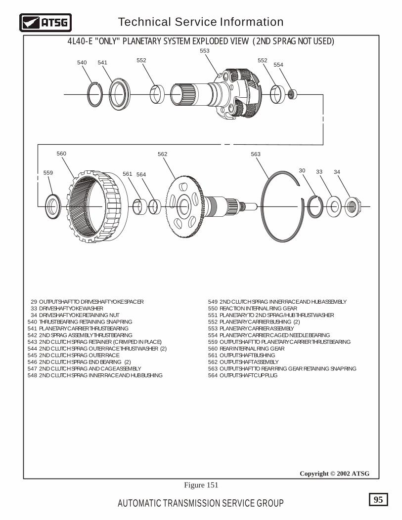
540 541
29 OUTPUT SHAFT TO DRIVESHAFT YOKE SPACER 33 DRIVESHAFT YOKE WASHER 34 DRIVESHAFT YOKE RETAINING NUT 540 THRUST BEARING RETAINING SNAP RING 541 PLANETARY CARRIER THRUST BEARING 542 2ND SPRAG ASSEMBLY THRUST BEARING 543 2ND CLUTCH SPRAG RETAINER (CRIMPED IN PLACE) 544 2ND CLUTCH SPRAG OUTER RACE THRUST WASHER (2) 545 2ND CLUTCH SPRAG OUTER RACE 546 2ND CLUTCH SPRAG END BEARING (2) 547 2ND CLUTCH SPRAG AND CAGE ASSEMBLY 548 2ND CLUTCH SPRAG INNER RACE AND HUB BUSHING
549 2ND CLUTCH SPRAG INNER RACE AND HUB ASSEMBLY 550 REACTION INTERNAL RING GEAR 551 PLANETARY TO 2ND SPRAG/HUB THRUST WASHER 552 PLANETARY CARRIER BUSHING (2) 553 PLANETARY CARRIER ASSEMBLY 554 PLANETARY CARRIER CAGED NEEDLE BEARING 559 OUTPUT SHAFT TO PLANETARY CARRIER THRUST BEARING 560 REAR INTERNAL RING GEAR 561 OUTPUT SHAFT BUSHING 562 OUTPUT SHAFT ASSEMBLY 563 OUTPUT SHAFT TO REAR RING GEAR RETAINING SNAP RING 564 OUTPUT SHAFT CUP PLUG
AUTOMATIC TRANSMISSION SERVICE GROUP
Technical Service Information
95
Copyright © 2002 ATSG
4L40-E "ONLY" PLANETARY SYSTEM EXPLODED VIEW (2ND SPRAG NOT USED)
559
560
561 564
562 563
30 33 34
552
553
552554
Figure 151
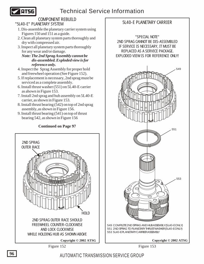
AUTOMATIC TRANSMISSION SERVICE GROUP
Technical Service Information
96
Copyright © 2002 ATSG
FR LEE EEWH
Copyright © 2002 ATSG
2ND SPRAG OUTER RACE SHOULDFREEWHEEL COUNTER-CLOCKWISE
AND LOCK CLOCKWISEWHILE HOLDING HUB AS SHOWN ABOVE
"SPECIAL NOTE"2ND SPRAG CANNOT BE DIS-ASSEMBLEDIF SERVICE IS NECESSARY, IT MUST BE
REPLACED AS A SERVICE PACKAGE.EXPLODED VIEW IS FOR REFERENCE ONLY!
HOLD
2ND SPRAGOUTER RACE
549
551
553
549 COMPLETE 2ND SPRAG AND HUB ASSEMBLY (5L40-E ONLY) 551 2ND SPRAG TO PLANETARY THRUST WASHER (5L40-E ONLY) 553 5L40-E PLANETARY CARRIER ASSEMBLY
5L40-E PLANETARY CARRIERCOMPONENT REBUILD
"5L40-E" PLANETARY SYSTEM
Figure 152 Figure 153
1. Dis-assemble the planetary carrier system using Figures 150 and 151 as a guide. 2. Clean all planetary system parts thoroughly and dry with compressed air. 3. Inspect all planetary system parts thoroughly for any wear and/or damage. Note: The 2nd Sprag Assembly cannot be dis-assembled. Exploded view is for reference only. 4. Inspect the Sprag Assembly for proper hold and freewheel operation (See Figure 152). 5. If replacement is necessary, 2nd sprag must be serviced as a complete assembly. 6. Install thrust washer (551) on 5L40-E carrier as ahown in Figure 153. 7. Install 2nd sprag and hub assembly on 5L40-E carrier, as shown in Figure 153. 8. Install thrust bearing (542) on top of 2nd sprag assembly, as shown in Figure 156. 9. Install thrust bearing (541) on top of thrust bearing 542, as shown in Figure 156
Continued on Page 97
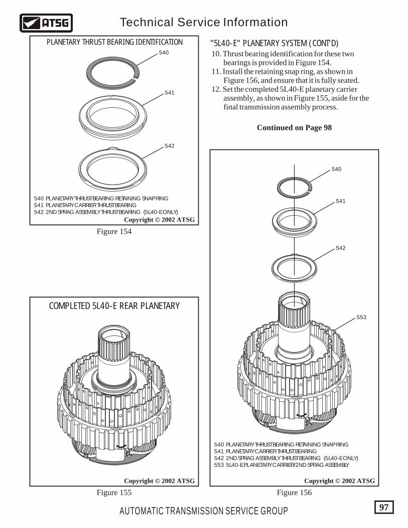
540 PLANETARY THRUST BEARING RETAINING SNAP RING 541 PLANETARY CARRIER THRUST BEARING 542 2ND SPRAG ASSEMBLY THRUST BEARING (5L40-E ONLY)
540 PLANETARY THRUST BEARING RETAINING SNAP RING 541 PLANETARY CARRIER THRUST BEARING 542 2ND SPRAG ASSEMBLY THRUST BEARING (5L40-E ONLY) 553 5L40-E PLANETARY CARRIER/2ND SPRAG ASSEMBLY
AUTOMATIC TRANSMISSION SERVICE GROUP
Technical Service Information
97
Copyright © 2002 ATSG
Copyright © 2002 ATSG
553
542
542
541
541
540
540
PLANETARY THRUST BEARING IDENTIFICATION
Copyright © 2002 ATSG
COMPLETED 5L40-E REAR PLANETARY
Figure 155
Figure 154
Figure 156
"5L40-E" PLANETARY SYSTEM (CONT'D) 10. Thrust bearing identification for these two bearings is provided in Figure 154. 11. Install the retaining snap ring, as shown in Figure 156, and ensure that it is fully seated. 12. Set the completed 5L40-E planetary carrier assembly, as shown in Figure 155, aside for the final transmission assembly process.
Continued on Page 98
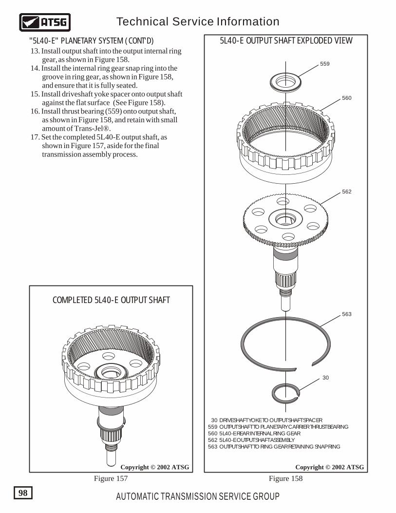
AUTOMATIC TRANSMISSION SERVICE GROUP
Technical Service Information
98
Copyright © 2002 ATSG
559
560
562
563
30
30 DRIVESHAFT YOKE TO OUTPUT SHAFT SPACER 559 OUTPUT SHAFT TO PLANETARY CARRIER THRUST BEARING 560 5L40-E REAR INTERNAL RING GEAR 562 5L40-E OUTPUT SHAFT ASSEMBLY 563 OUTPUT SHAFT TO RING GEAR RETAINING SNAP RING
5L40-E OUTPUT SHAFT EXPLODED VIEW"5L40-E" PLANETARY SYSTEM (CONT'D)
Copyright © 2002 ATSG
COMPLETED 5L40-E OUTPUT SHAFT
Figure 157 Figure 158
13. Install output shaft into the output internal ring gear, as shown in Figure 158. 14. Install the internal ring gear snap ring into the groove in ring gear, as shown in Figure 158, and ensure that it is fully seated. 15. Install driveshaft yoke spacer onto output shaft against the flat surface (See Figure 158). 16. Install thrust bearing (559) onto output shaft, as shown in Figure 158, and retain with small amount of Trans-Jel®. 17. Set the completed 5L40-E output shaft, as shown in Figure 157, aside for the final transmission assembly process.
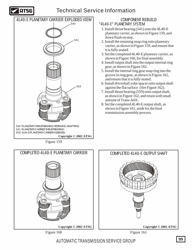
540 PLANETARY THRUST BEARING RETAINING SNAP RING 541 PLANETARY CARRIER THRUST BEARING 553 4L40-E PLANETARY CARRIER ASSEMBLY
AUTOMATIC TRANSMISSION SERVICE GROUP
Technical Service Information
99
Copyright © 2002 ATSG
Copyright © 2002 ATSG
COMPLETED 4L40-E PLANETARY CARRIER
4L40-E PLANETARY CARRIER EXPLODED VIEW"4L40-E" PLANETARY SYSTEM
COMPONENT REBUILD
553
541
540
Figure 159
Figure 160 Figure 161
1. Install thrust bearing (541) onto the 4L40-E planetary carrier, as shown in Figure 159, and down flush on step. 2. Install the retaining snap ring onto planetary carrier, as shown in Figure 159, and ensure that it is fully seated. 3. Set the completed 4L40-E planetary carrier, as shown in Figure 160, for final assembly. 4. Install output shaft into the output internal ring gear, as shown in Figure 162. 5. Install the internal ring gear snap ring into the groove in ring gear, as shown in Figure 162, and ensure that it is fully seated. 6. Install driveshaft yoke spacer onto output shaft against the flat surface (See Figure 162). 7. Install thrust bearing (559) onto output shaft, as shown in Figure 162, and retain with small amount of Trans-Jel®. 8. Set the completed 4L40-E output shaft, as shown in Figure 161, aside for the final transmission assembly process.
Copyright © 2002 ATSG
COMPLETED 4L40-E OUTPUT SHAFT
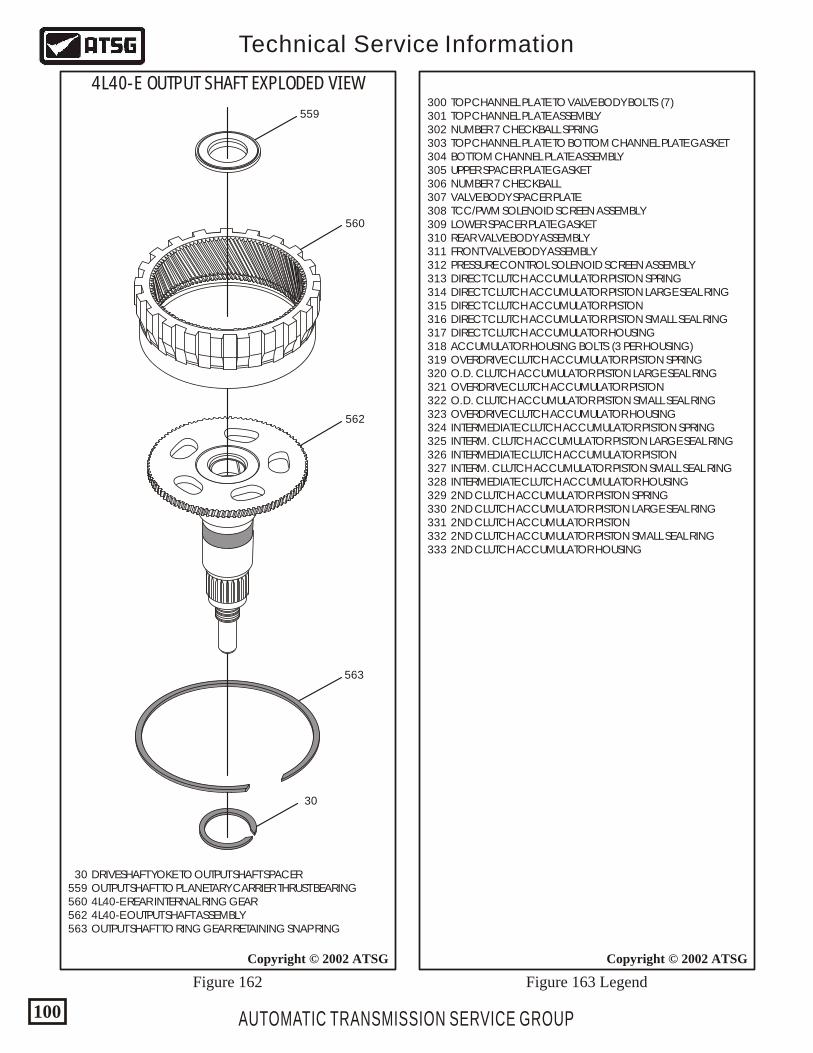
AUTOMATIC TRANSMISSION SERVICE GROUP
Technical Service Information
100
Copyright © 2002 ATSG
300 TOP CHANNEL PLATE TO VALVE BODY BOLTS (7) 301 TOP CHANNEL PLATE ASSEMBLY 302 NUMBER 7 CHECKBALL SPRING 303 TOP CHANNEL PLATE TO BOTTOM CHANNEL PLATE GASKET 304 BOTTOM CHANNEL PLATE ASSEMBLY 305 UPPER SPACER PLATE GASKET 306 NUMBER 7 CHECKBALL 307 VALVE BODY SPACER PLATE 308 TCC/PWM SOLENOID SCREEN ASSEMBLY 309 LOWER SPACER PLATE GASKET 310 REAR VALVE BODY ASSEMBLY 311 FRONT VALVE BODY ASSEMBLY 312 PRESSURE CONTROL SOLENOID SCREEN ASSEMBLY 313 DIRECT CLUTCH ACCUMULATOR PISTON SPRING 314 DIRECT CLUTCH ACCUMULATOR PISTON LARGE SEAL RING 315 DIRECT CLUTCH ACCUMULATOR PISTON 316 DIRECT CLUTCH ACCUMULATOR PISTON SMALL SEAL RING 317 DIRECT CLUTCH ACCUMULATOR HOUSING 318 ACCUMULATOR HOUSING BOLTS (3 PER HOUSING) 319 OVERDRIVE CLUTCH ACCUMULATOR PISTON SPRING 320 O.D. CLUTCH ACCUMULATOR PISTON LARGE SEAL RING 321 OVERDRIVE CLUTCH ACCUMULATOR PISTON 322 O.D. CLUTCH ACCUMULATOR PISTON SMALL SEAL RING 323 OVERDRIVE CLUTCH ACCUMULATOR HOUSING 324 INTERMEDIATE CLUTCH ACCUMULATOR PISTON SPRING 325 INTERM. CLUTCH ACCUMULATOR PISTON LARGE SEAL RING 326 INTERMEDIATE CLUTCH ACCUMULATOR PISTON 327 INTERM. CLUTCH ACCUMULATOR PISTON SMALL SEAL RING 328 INTERMEDIATE CLUTCH ACCUMULATOR HOUSING 329 2ND CLUTCH ACCUMULATOR PISTON SPRING 330 2ND CLUTCH ACCUMULATOR PISTON LARGE SEAL RING 331 2ND CLUTCH ACCUMULATOR PISTON 332 2ND CLUTCH ACCUMULATOR PISTON SMALL SEAL RING 333 2ND CLUTCH ACCUMULATOR HOUSING
Copyright © 2002 ATSG
559
560
562
563
30
30 DRIVESHAFT YOKE TO OUTPUT SHAFT SPACER 559 OUTPUT SHAFT TO PLANETARY CARRIER THRUST BEARING 560 4L40-E REAR INTERNAL RING GEAR 562 4L40-E OUTPUT SHAFT ASSEMBLY 563 OUTPUT SHAFT TO RING GEAR RETAINING SNAP RING
4L40-E OUTPUT SHAFT EXPLODED VIEW
Figure 162 Figure 163 Legend
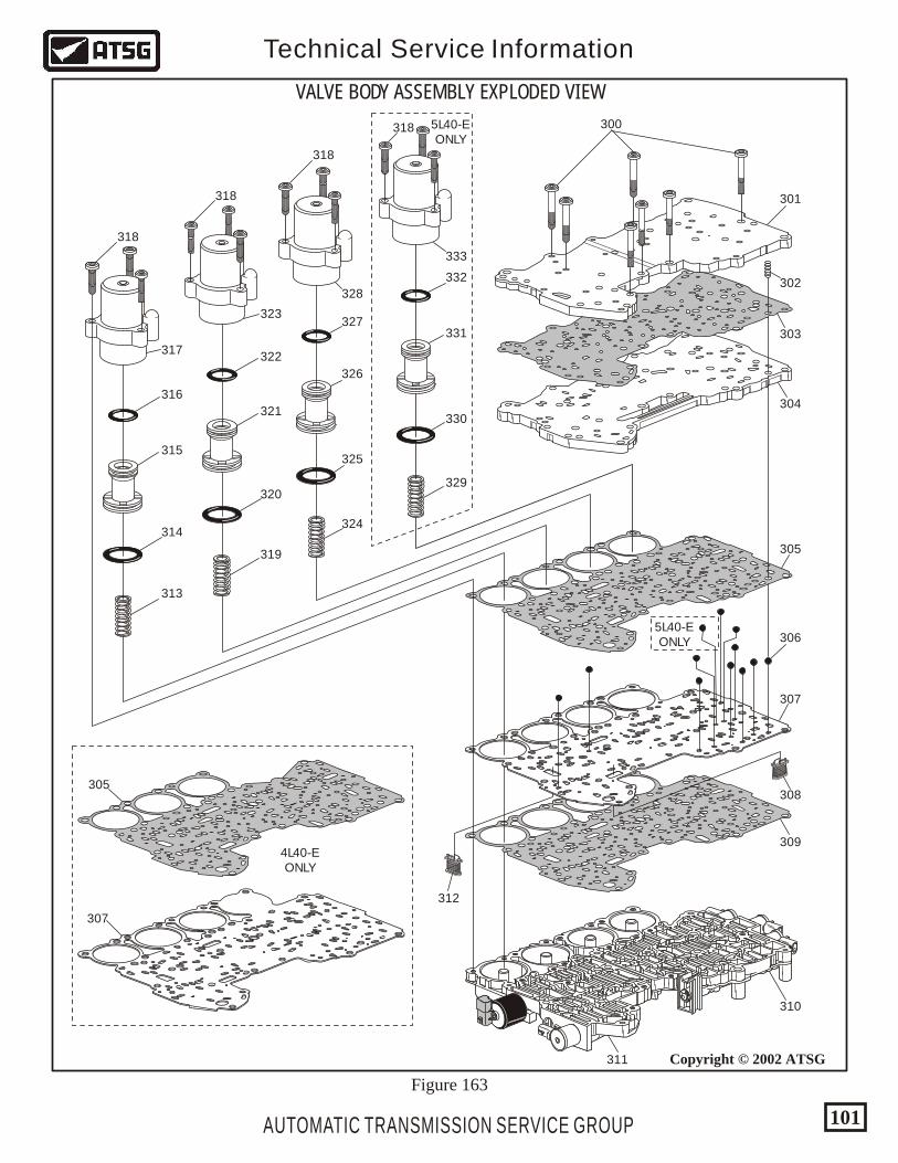
AUTOMATIC TRANSMISSION SERVICE GROUP
Technical Service Information
101
Copyright © 2002 ATSG
306
307
307
308
309
310
311
5L40-EONLY
5L40-EONLY
4L40-EONLY
305
304
303
302
301
300318
318
318
318
333
332
331
330
329
324
325
326
327
328
323
322
321
320
319
313
314
315
316
317
305
312
VALVE BODY ASSEMBLY EXPLODED VIEW
Figure 163
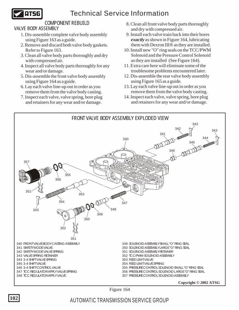
AUTOMATIC TRANSMISSION SERVICE GROUP
Technical Service Information
102
Copyright © 2002 ATSG
340
341
342
343
343
344
345
346
347
348
349
350
351
351
343
352
353
354
355
356
357
FRONT VALVE BODY ASSEMBLY EXPLODED VIEW
COMPONENT REBUILDVALVE BODY ASSEMBLY
340 FRONT VALVE BODY CASTING ASSEMBLY 341 SAFETY MODE VALVE 342 SAFETY MODE VALVE SPRING 343 VALVE SPRING RETAINER 344 3-4 SHIFT VALVE SPRING 345 3-4 SHIFT VALVE 346 3-4 SHIFT CONTROL VALVE 347 TCC REGULATOR APPLY VALVE SPRING 348 TCC REGULATOR APPLY VALVE
349 SOLENOID ASSEMBLY SMALL "O" RING SEAL 350 SOLENOID ASSEMBLY LARGE "O" RING SEAL 351 SOLENOID ASSEMBLY RETAINER 352 TCC/PWM SOLENOID ASSEMBLY 353 FEED LIMIT VALVE 354 FEED LIMIT VALVE SPRING 355 PRESSURE CONTROL SOLENOID SMALL "O" RING SEAL 356 PRESSURE CONTROL SOLENOID LARGE "O" RING SEAL 357 PRESSURE CONTROL SOLENOID ASSEMBLY
Figure 164
1. Dis-assemble complete valve body assembly using Figure 163 as a guide. 2. Remove and discard both valve body gaskets. Refer to Figure 163. 3. Clean all valve body parts thoroughly and dry with compressed air. 4. Inspect all valve body parts thoroughly for any wear and/or damage. 5. Dis-assemble the front valve body assembly using Figure 164 as a guide. 6. Lay each valve line-up out in order as you remove them from the valve body casting. 7. Inspect each valve, valve spring, bore plug and retainers for any wear and/or damage.
8. Clean all front valve body parts thoroughly and dry with compressed air. 9. Install each valve train back into their bores exactly as shown in Figure 164, lubricating them with Dexron III® as they are installed. 10. Install new "O" ring seals on the TCC/PWM Solenoid and the Pressure Control Solenoid as they are installed (See Figure 164). 11. Extra care here will eliminate some of the troublesome problems encountered later. 12. Dis-assemble the rear valve body assembly using Figure 165 as a guide. 13. Lay each valve line-up out in order as you remove them from the valve body casting. 14. Inspect each valve, valve spring, bore plug and retainers for any wear and/or damage.
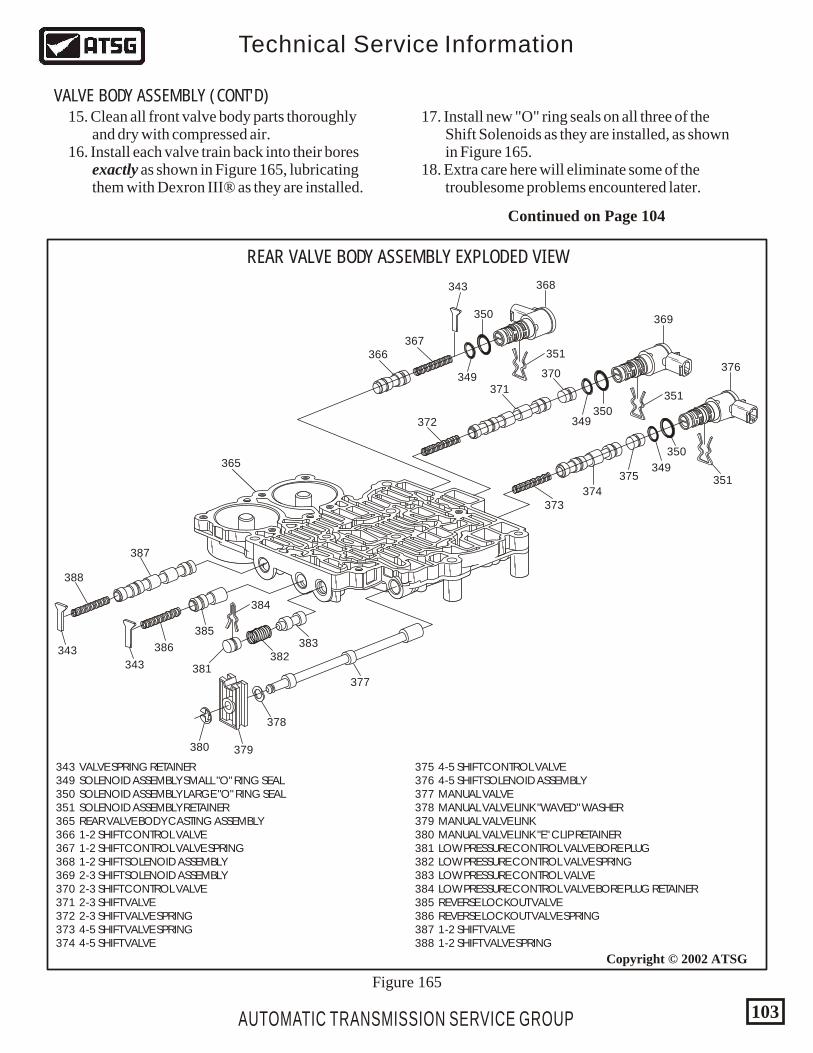
AUTOMATIC TRANSMISSION SERVICE GROUP
Technical Service Information
103
Copyright © 2002 ATSG
REAR VALVE BODY ASSEMBLY EXPLODED VIEW
343
349
350
351366367
368
349350
351
369
370
371
372
349
350
351
373374
375
376
377
378
379380
381382
383
384
385
386
387
365
388
343
343
343 VALVE SPRING RETAINER 349 SOLENOID ASSEMBLY SMALL "O" RING SEAL 350 SOLENOID ASSEMBLY LARGE "O" RING SEAL 351 SOLENOID ASSEMBLY RETAINER 365 REAR VALVE BODY CASTING ASSEMBLY 366 1-2 SHIFT CONTROL VALVE 367 1-2 SHIFT CONTROL VALVE SPRING 368 1-2 SHIFT SOLENOID ASSEMBLY 369 2-3 SHIFT SOLENOID ASSEMBLY 370 2-3 SHIFT CONTROL VALVE 371 2-3 SHIFT VALVE 372 2-3 SHIFT VALVE SPRING 373 4-5 SHIFT VALVE SPRING 374 4-5 SHIFT VALVE
375 4-5 SHIFT CONTROL VALVE 376 4-5 SHIFT SOLENOID ASSEMBLY 377 MANUAL VALVE 378 MANUAL VALVE LINK "WAVED" WASHER 379 MANUAL VALVE LINK 380 MANUAL VALVE LINK "E" CLIP RETAINER 381 LOW PRESSURE CONTROL VALVE BORE PLUG 382 LOW PRESSURE CONTROL VALVE SPRING 383 LOW PRESSURE CONTROL VALVE 384 LOW PRESSURE CONTROL VALVE BORE PLUG RETAINER 385 REVERSE LOCKOUT VALVE 386 REVERSE LOCKOUT VALVE SPRING 387 1-2 SHIFT VALVE 388 1-2 SHIFT VALVE SPRING
Figure 165
15. Clean all front valve body parts thoroughly and dry with compressed air. 16. Install each valve train back into their bores exactly as shown in Figure 165, lubricating them with Dexron III® as they are installed.
17. Install new "O" ring seals on all three of the Shift Solenoids as they are installed, as shown in Figure 165. 18. Extra care here will eliminate some of the troublesome problems encountered later.
Continued on Page 104
VALVE BODY ASSEMBLY (CONT'D)
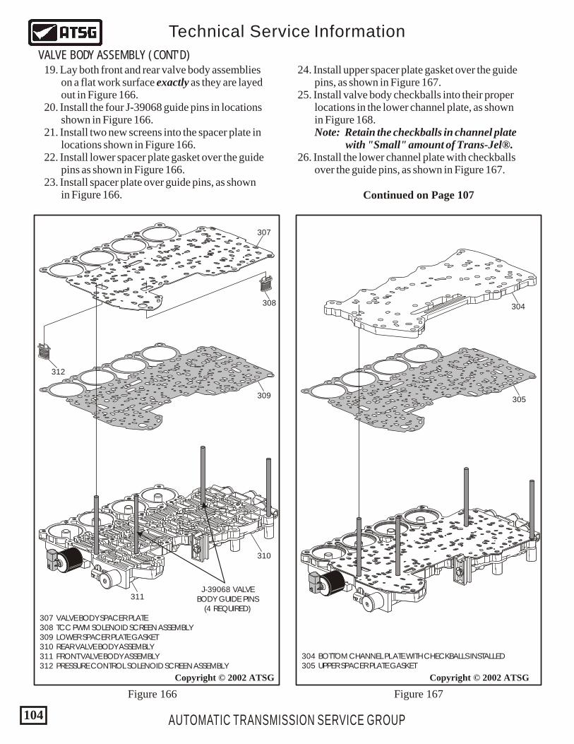
Copyright © 2002 ATSG
310
311J-39068 VALVE
BODY GUIDE PINS(4 REQUIRED)
309
307
308
312
307 VALVE BODY SPACER PLATE 308 TCC PWM SOLENOID SCREEN ASSEMBLY 309 LOWER SPACER PLATE GASKET 310 REAR VALVE BODY ASSEMBLY 311 FRONT VALVE BODY ASSEMBLY 312 PRESSURE CONTROL SOLENOID SCREEN ASSEMBLY
304 BOTTOM CHANNEL PLATE WITH CHECKBALLS INSTALLED 305 UPPER SPACER PLATE GASKET
AUTOMATIC TRANSMISSION SERVICE GROUP
Technical Service Information
104
Copyright © 2002 ATSG
305
304
VALVE BODY ASSEMBLY (CONT'D) 19. Lay both front and rear valve body assemblies on a flat work surface exactly as they are layed out in Figure 166. 20. Install the four J-39068 guide pins in locations shown in Figure 166. 21. Install two new screens into the spacer plate in locations shown in Figure 166. 22. Install lower spacer plate gasket over the guide pins as shown in Figure 166. 23. Install spacer plate over guide pins, as shown in Figure 166.
24. Install upper spacer plate gasket over the guide pins, as shown in Figure 167. 25. Install valve body checkballs into their proper locations in the lower channel plate, as shown in Figure 168. Note: Retain the checkballs in channel plate with "Small" amount of Trans-Jel®. 26. Install the lower channel plate with checkballs over the guide pins, as shown in Figure 167.
Figure 166 Figure 167
Continued on Page 107
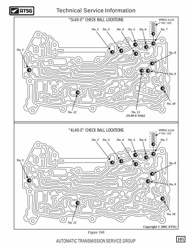
"5L40-E" CHECK BALL LOCATIONS
"4L40-E" CHECK BALL LOCATIONS
No. 2
No. 2
No. 3
No. 3
No. 4
No. 4
No. 5
No. 5
No. 6
No. 6
No. 7
No. 7
No. 8
No. 8
No. 9
No. 9
No. 10
No. 10
No. 11(5L40-E Only)
No. 12
No. 12
No. 1
No. 1
SPRING ILLUS.NO. 302
SPRING ILLUS.NO. 302
AUTOMATIC TRANSMISSION SERVICE GROUP
Technical Service Information
105
Copyright © 2002 ATSG
Figure 168
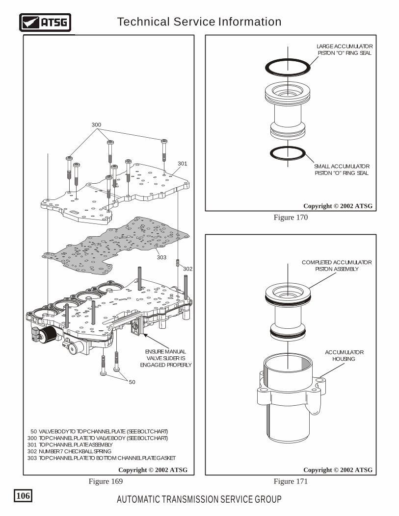
AUTOMATIC TRANSMISSION SERVICE GROUP
Technical Service Information
106
Copyright © 2002 ATSG
Copyright © 2002 ATSG
Copyright © 2002 ATSG
300
50
303
302
301
LARGE ACCUMULATORPISTON "O" RING SEAL
SMALL ACCUMULATORPISTON "O" RING SEAL
COMPLETED ACCUMULATORPISTON ASSEMBLY
ACCUMULATORHOUSING
50 VALVE BODY TO TOP CHANNEL PLATE (SEE BOLT CHART) 300 TOP CHANNEL PLATE TO VALVE BODY (SEE BOLT CHART) 301 TOP CHANNEL PLATE ASSEMBLY 302 NUMBER 7 CHECKBALL SPRING 303 TOP CHANNEL PLATE TO BOTTOM CHANNEL PLATE GASKET
ENSURE MANUALVALVE SLIDER IS
ENGAGED PROPERLY
Figure 169 Figure 171
Figure 170
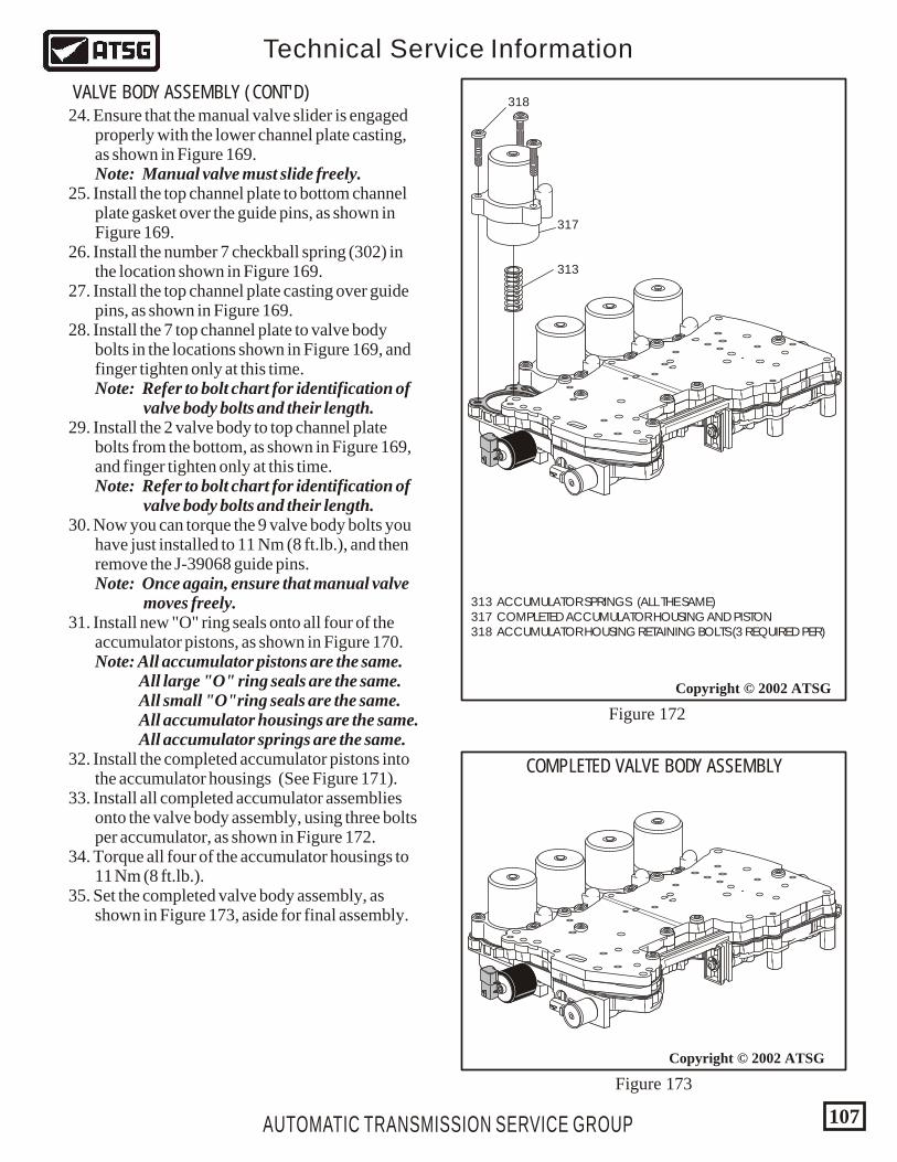
Copyright © 2002 ATSG
313 ACCUMULATOR SPRINGS (ALL THE SAME) 317 COMPLETED ACCUMULATOR HOUSING AND PISTON 318 ACCUMULATOR HOUSING RETAINING BOLTS (3 REQUIRED PER)
AUTOMATIC TRANSMISSION SERVICE GROUP
Technical Service Information
107
Copyright © 2002 ATSG
318
313
317
COMPLETED VALVE BODY ASSEMBLY
Figure 172
Figure 173
24. Ensure that the manual valve slider is engaged properly with the lower channel plate casting, as shown in Figure 169. Note: Manual valve must slide freely. 25. Install the top channel plate to bottom channel plate gasket over the guide pins, as shown in Figure 169. 26. Install the number 7 checkball spring (302) in the location shown in Figure 169. 27. Install the top channel plate casting over guide pins, as shown in Figure 169. 28. Install the 7 top channel plate to valve body bolts in the locations shown in Figure 169, and finger tighten only at this time. Note: Refer to bolt chart for identification of valve body bolts and their length. 29. Install the 2 valve body to top channel plate bolts from the bottom, as shown in Figure 169, and finger tighten only at this time. Note: Refer to bolt chart for identification of valve body bolts and their length. 30. Now you can torque the 9 valve body bolts you have just installed to 11 Nm (8 ft.lb.), and then remove the J-39068 guide pins. Note: Once again, ensure that manual valve moves freely. 31. Install new "O" ring seals onto all four of the accumulator pistons, as shown in Figure 170. Note: All accumulator pistons are the same. All large "O" ring seals are the same. All small "O"ring seals are the same. All accumulator housings are the same. All accumulator springs are the same. 32. Install the completed accumulator pistons into the accumulator housings (See Figure 171). 33. Install all completed accumulator assemblies onto the valve body assembly, using three bolts per accumulator, as shown in Figure 172. 34. Torque all four of the accumulator housings to 11 Nm (8 ft.lb.). 35. Set the completed valve body assembly, as shown in Figure 173, aside for final assembly.
VALVE BODY ASSEMBLY (CONT'D)
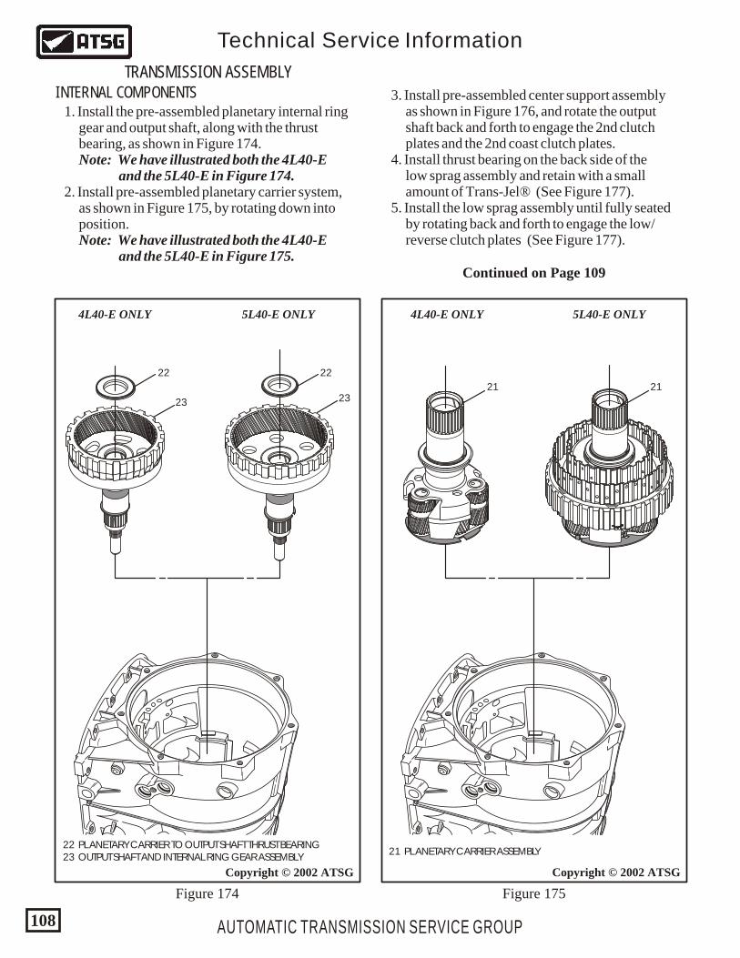
AUTOMATIC TRANSMISSION SERVICE GROUP
Technical Service Information
108
Copyright © 2002 ATSG
2222
2323
22 PLANETARY CARRIER TO OUTPUT SHAFT THRUST BEARING 23 OUTPUT SHAFT AND INTERNAL RING GEAR ASSEMBLY
5L40-E ONLY4L40-E ONLY
Figure 174
1. Install the pre-assembled planetary internal ring gear and output shaft, along with the thrust bearing, as shown in Figure 174. Note: We have illustrated both the 4L40-E and the 5L40-E in Figure 174. 2. Install pre-assembled planetary carrier system, as shown in Figure 175, by rotating down into position. Note: We have illustrated both the 4L40-E and the 5L40-E in Figure 175.
INTERNAL COMPONENTS
TRANSMISSION ASSEMBLY
Figure 175
2121
21 PLANETARY CARRIER ASSEMBLY
Copyright © 2002 ATSG
5L40-E ONLY4L40-E ONLY
3. Install pre-assembled center support assembly as shown in Figure 176, and rotate the output shaft back and forth to engage the 2nd clutch plates and the 2nd coast clutch plates. 4. Install thrust bearing on the back side of the low sprag assembly and retain with a small amount of Trans-Jel® (See Figure 177). 5. Install the low sprag assembly until fully seated by rotating back and forth to engage the low/ reverse clutch plates (See Figure 177).
Continued on Page 109
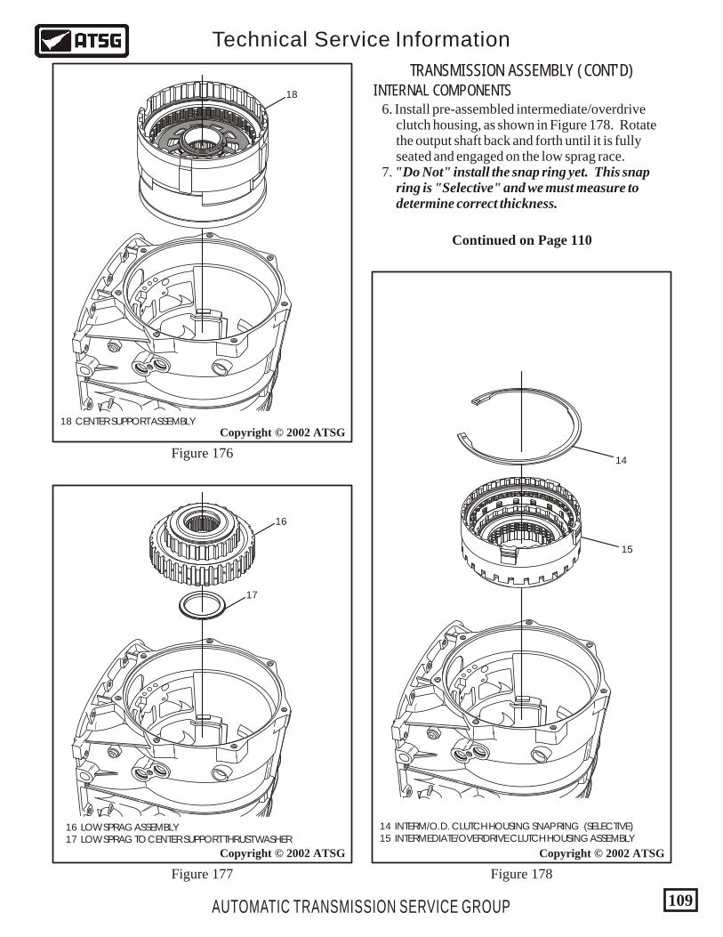
AUTOMATIC TRANSMISSION SERVICE GROUP
Technical Service Information
109
16
17
18 CENTER SUPPORT ASSEMBLY
16 LOW SPRAG ASSEMBLY 17 LOW SPRAG TO CENTER SUPPORT THRUST WASHER
6. Install pre-assembled intermediate/overdrive clutch housing, as shown in Figure 178. Rotate the output shaft back and forth until it is fully seated and engaged on the low sprag race. 7. "Do Not" install the snap ring yet. This snap ring is "Selective" and we must measure to determine correct thickness.
INTERNAL COMPONENTS
TRANSMISSION ASSEMBLY (CONT'D)
Copyright © 2002 ATSG
Copyright © 2002 ATSG
18
Figure 176
Figure 177
Copyright © 2002 ATSG
Figure 178
14
15
14 INTERM/O.D. CLUTCH HOUSING SNAP RING (SELECTIVE) 15 INTERMEDIATE/OVERDRIVE CLUTCH HOUSING ASSEMBLY
Continued on Page 110
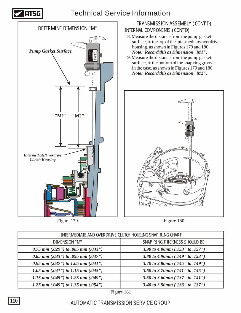
8. Measure the distance from the pump gasket surface, to the top of the intermediate/overdrive housing, as shown in Figures 179 and 180. Note: Record this as Dimension "M1". 9. Measure the distance from the pump gasket surface, to the bottom of the snap ring groove in the case, as shown in Figures 179 and 180. Note: Record this as Dimension "M2".
INTERNAL COMPONENTS (CONT'D)DETERMINE DIMENSION "M"TRANSMISSION ASSEMBLY (CONT'D)
AUTOMATIC TRANSMISSION SERVICE GROUP
Technical Service Information
110
Figure 181
Figure 180
"M1" "M2"
INTERMEDIATE AND OVERDRIVE CLUTCH HOUSING SNAP RING CHART
SNAP RING THICKNESS SHOULD BE:DIMENSION "M"
0.75 mm (.029") to .085 mm (.033")
0.85 mm (.033") to .095 mm (.037")
0.95 mm (.037") to 1.05 mm (.041")
1.05 mm (.041") to 1.15 mm (.045")
1.15 mm (.045") to 1.25 mm (.049")
1.25 mm (.049") to 1.35 mm (.054")
3.90 to 4.00mm (.153" to .157")
3.80 to 4.90mm (.149" to .153")
3.70 to 3.80mm (.145" to .149")
3.60 to 3.70mm (.141" to .145")
3.50 to 3.60mm (.137" to .141")
3.40 to 3.50mm (.133" to .137")
Pump Gasket Surface
Intermediate/OverdriveClutch Housing
34
56
78
91
23
45
67
89
56
150
140
130
120
in
mm
EL
EC
TR
ON
ICD
IGIT
AL
CA
LIP
ER
AU
TO P
OW
ER
-OFF
AU
TO P
OW
ER
-OFF
mm
/inm
m/in
00
04.249IN
43
21
12
34
56
78
91
23
45
67
89
12
34
56
78
91
23
45
67
89
12
34
56
78
91
23
45
67
89
56
10
20
30
40
50
60
70
80
90
150
140
130
120
110
100
0
in
mm
EL
EC
TR
ON
ICD
IGIT
AL
CA
LIP
ER
AU
TO P
OW
ER
-OFF
AU
TO P
OW
ER
-OFF
mm
/inm
m/in
00
00.945IN
Figure 179
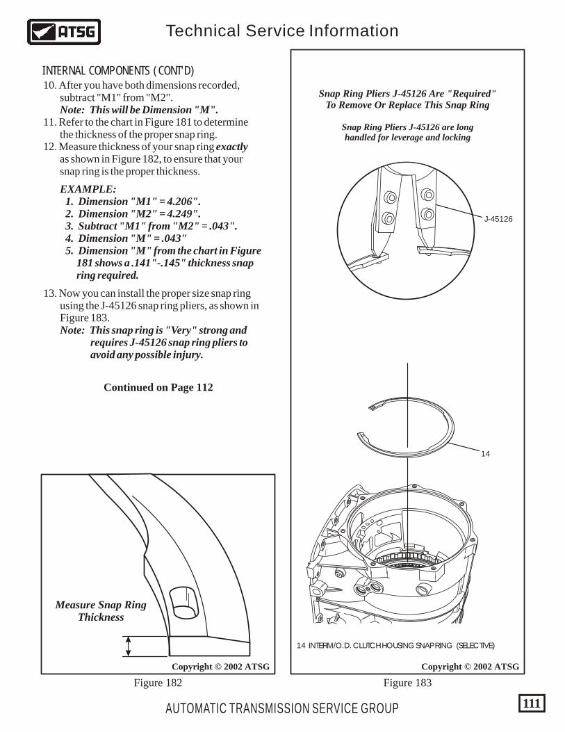
AUTOMATIC TRANSMISSION SERVICE GROUP
Technical Service Information
111
Copyright © 2002 ATSGCopyright © 2002 ATSG
Figure 183Figure 182
14
J-45126
14 INTERM/O.D. CLUTCH HOUSING SNAP RING (SELECTIVE)
Snap Ring Pliers J-45126 Are "Required"To Remove Or Replace This Snap Ring
Snap Ring Pliers J-45126 are longhandled for leverage and locking
10. After you have both dimensions recorded, subtract "M1" from "M2". Note: This will be Dimension "M". 11. Refer to the chart in Figure 181 to determine the thickness of the proper snap ring. 12. Measure thickness of your snap ring exactly as shown in Figure 182, to ensure that your snap ring is the proper thickness.
INTERNAL COMPONENTS (CONT'D)
Measure Snap RingThickness
EXAMPLE: 1. Dimension "M1" = 4.206". 2. Dimension "M2" = 4.249". 3. Subtract "M1" from "M2" = .043". 4. Dimension "M" = .043" 5. Dimension "M" from the chart in Figure 181 shows a .141"-.145" thickness snap ring required.
13. Now you can install the proper size snap ring using the J-45126 snap ring pliers, as shown in Figure 183. Note: This snap ring is "Very" strong and requires J-45126 snap ring pliers to avoid any possible injury.
Continued on Page 112
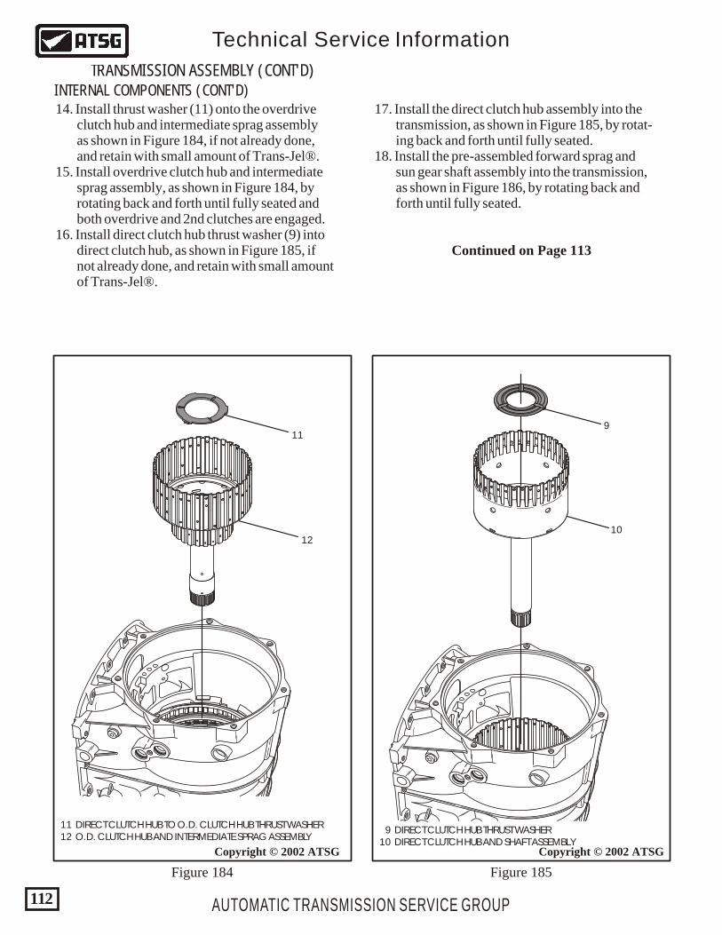
14. Install thrust washer (11) onto the overdrive clutch hub and intermediate sprag assembly as shown in Figure 184, if not already done, and retain with small amount of Trans-Jel®. 15. Install overdrive clutch hub and intermediate sprag assembly, as shown in Figure 184, by rotating back and forth until fully seated and both overdrive and 2nd clutches are engaged. 16. Install direct clutch hub thrust washer (9) into direct clutch hub, as shown in Figure 185, if not already done, and retain with small amount of Trans-Jel®.
17. Install the direct clutch hub assembly into the transmission, as shown in Figure 185, by rotat- ing back and forth until fully seated. 18. Install the pre-assembled forward sprag and sun gear shaft assembly into the transmission, as shown in Figure 186, by rotating back and forth until fully seated.
INTERNAL COMPONENTS (CONT'D)
TRANSMISSION ASSEMBLY (CONT'D)
AUTOMATIC TRANSMISSION SERVICE GROUP
Technical Service Information
112
9 DIRECT CLUTCH HUB THRUST WASHER 10 DIRECT CLUTCH HUB AND SHAFT ASSEMBLY
10
9
Copyright © 2002 ATSG
Figure 185
Continued on Page 113
12
11
Copyright © 2002 ATSG
Figure 184
11 DIRECT CLUTCH HUB TO O.D. CLUTCH HUB THRUST WASHER 12 O.D. CLUTCH HUB AND INTERMEDIATE SPRAG ASSEMBLY
AUTOMATIC TRANSMISSION SERVICE GROUP
Technical Service Information
113
8
Copyright © 2002 ATSG
8 FORWARD SPRAG ASSEMBLY AND INPUT SUN GEAR SHAFT
Figure 186 Figure 187
Copyright © 2002 ATSG
6
7
6 DIRECT AND REVERSE CLUTCH HOUSING ASSEMBLY 7 FORWARD AND COAST CLUTCH HOUSING ASSEMBLY
19. Install the reverse clutch housing on forward and coast clutch housing by rotating back and forth to engage the reverse clutch plates, until fully seated and splines engaged on forward clutch housing (See Figure 187).
Continued on Page 114
INTERNAL COMPONENTS (CONT'D)
AUTOMATIC TRANSMISSION SERVICE GROUP
Technical Service Information
114
INTERNAL COMPONENTS (CONT'D)
TRANSMISSION ASSEMBLY (CONT'D)
20. Install the pre-assembled forward/coast clutch housing and reverse clutch housing as assembly as shown in Figure 188, by rotating back and forth to engage the three sets of clutches. 21. Install the "H" gage on top surface of the case, as shown in Figure 189, loosen adjusting knob and allow gage rod to rest on washer surface of reverse clutch housing (See Figure 189). 22. Remove "H" gage from case, turn it over and install on surface of converter housing as it is shown in Figure 190.
23. Measure with feeler gage between the gage rod and the current "Selective" thrust washer being used, as shown in Figure 190. 24. Front end clearance should be: 0.76 - 1.02 mm (.030" - .040"). Change the selective thrust washer as necessary to achieve the proper front end clearance. 25. Refer to chart in Figure 190 for the different thickness thrust washers that are available.
Copyright © 2002 ATSG Copyright © 2002 ATSG
Forward And Reverse DrumsInstalled As Assembly
Figure 188 Figure 189
Continued on Page 115
AUTOMATIC TRANSMISSION SERVICE GROUP
Technical Service Information
115
Copyright © 2002 ATSGCopyright © 2002 ATSG
230
GM
832
96 022
HYD
RAM
ATIC
STR
AS
BU
RG
FRAN
CE
*0139781R
VO
*
6 66 66 66 6
1/8
226
2.1226
2.1226
2.1226
2.1
nat
230 CONVERTER HOUSING TO MAIN CASE "O" RING SEAL
GM
832
96 022
HYD
RAM
ATIC
STR
AS
BU
RG
FRAN
CE
*0139781R
VO
*
6 66 66 66 6
1/8
226
2.1226
2.1226
2.1226
2.1
nat
Figure 190 Figure 191
CHECKING FRONT END CLEARANCE
THRUST WASHERS AVAILABLE
CLEARANCE SHOULD BE .030" TO .040"
2.53-2.68 mm (.099"-.105")
2.71-2.86 mm (.106"-.112")
2.89-3.04 mm (.113"-.119")
3.05-3.20 mm (.120"-.125")
3.25-3.40 mm (.127"-.133")
3.43-3.58 mm (.135"-.140")
3.61-3.76 mm (.142"-.148")
3.79-3.94 mm (.149"-.155")
26. Ensure that the converter housing to case "O" ring seal is in place on the converter housing. If not, install it now as shown in Figure 191 and retain with small amount of Trans-Jel®.
INTERNAL COMPONENTS (CONT'D)
Continued on Page 116
AUTOMATIC TRANSMISSION SERVICE GROUP
Technical Service Information
116
Copyright © 2002 ATSG Copyright © 2002 ATSG
INTERNAL COMPONENTS (CONT'D)
TRANSMISSION ASSEMBLY (CONT'D)
27. Install the molded pump to case gasket (46) onto the back side of pump cover, as shown in Figure 192, using the molded guide pins. 28. Retain with a small amount of Trans-Jel®, if necessary. 29. Install complete converter housing assembly onto case, as shown in Figure 192. 30. Install the seven converter housing to case bolts, as shown in Figure 192. Refer to the bolt chart to identify proper bolts. 31. Torque the seven bolts to 22 Nm (16 ft,lb.), as shown in Figure 194. 32. Use the torque sequence in a cris-cross pattern, as shown in Figure 193. 33. Install the turbine shaft "O" ring seal using a small screwdriver, as shown in Figure 195, and lubricate with small amount of Trans-Jel®.
2 BELL HOUSING RETAINING BOLTS (7 REQUIRED) 3 BELL HOUSING AND PUMP ASSEMBLY 4 BELL HOUSING TO CASE SEAL
46
2
3
4
Figure 192 Figure 193
1
2
3
4
5
6
7
CONVERTER HOUSINGTORQUE SEQUENCE
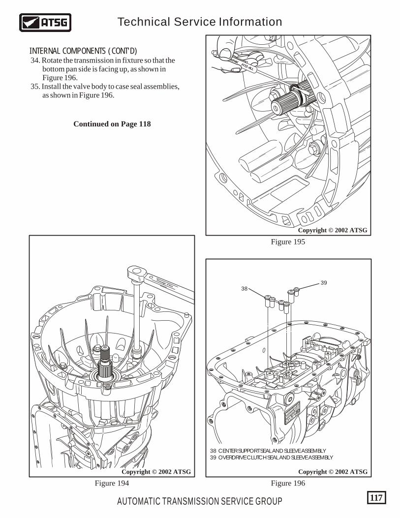
AUTOMATIC TRANSMISSION SERVICE GROUP
Technical Service Information
117
Figure 194
38 CENTER SUPPORT SEAL AND SLEEVE ASSEMBLY 39 OVERDRIVE CLUTCH SEAL AND SLEEVE ASSEMBLY
Copyright © 2002 ATSG
3839
HYDRAMATIC
STRASBOURG
MADE IN FRANCE
SERIAL NO. 1 423 875
013978196022832
P08
VO
_ __ _
PART NO.
TCM
CAL.
GM
Figure 195
Figure 196
Snap-On
Copyright © 2002 ATSG
TECKPAKFITZ-ALL
Copyright © 2002 ATSG
INTERNAL COMPONENTS (CONT'D) 34. Rotate the transmission in fixture so that the bottom pan side is facing up, as shown in Figure 196. 35. Install the valve body to case seal assemblies, as shown in Figure 196.
Continued on Page 118
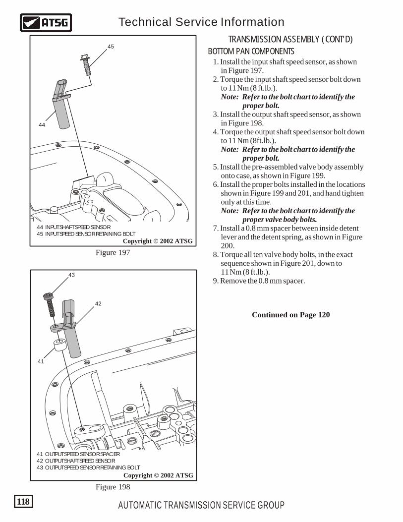
AUTOMATIC TRANSMISSION SERVICE GROUP
Technical Service Information
118
BOTTOM PAN COMPONENTS
TRANSMISSION ASSEMBLY (CONT'D)
1. Install the input shaft speed sensor, as shown in Figure 197. 2. Torque the input shaft speed sensor bolt down to 11 Nm (8 ft.lb.). Note: Refer to the bolt chart to identify the proper bolt. 3. Install the output shaft speed sensor, as shown in Figure 198. 4. Torque the output shaft speed sensor bolt down to 11 Nm (8ft.lb.). Note: Refer to the bolt chart to identify the proper bolt. 5. Install the pre-assembled valve body assembly onto case, as shown in Figure 199. 6. Install the proper bolts installed in the locations shown in Figure 199 and 201, and hand tighten only at this time. Note: Refer to the bolt chart to identify the proper valve body bolts. 7. Install a 0.8 mm spacer between inside detent lever and the detent spring, as shown in Figure 200. 8. Torque all ten valve body bolts, in the exact sequence shown in Figure 201, down to 11 Nm (8 ft.lb.). 9. Remove the 0.8 mm spacer.
Continued on Page 120
44 INPUT SHAFT SPEED SENSOR 45 INPUT SPEED SENSOR RETAINING BOLT
Copyright © 2002 ATSG
Copyright © 2002 ATSG
41 OUTPUT SPEED SENSOR SPACER 42 OUTPUT SHAFT SPEED SENSOR 43 OUTPUT SPEED SENSOR RETAINING BOLT
41
42
44
45
43
Figure 197
Figure 198
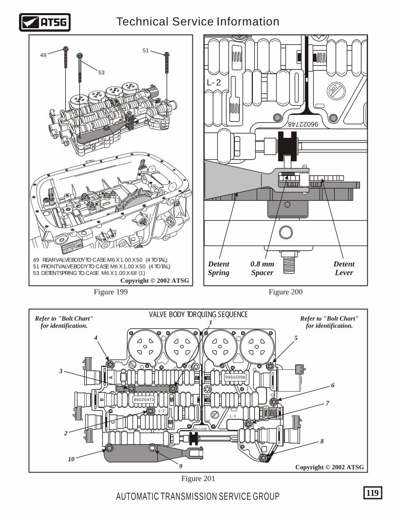
AUTOMATIC TRANSMISSION SERVICE GROUP
Technical Service Information
119
Copyright © 2002 ATSG
Figure 201
96022748
78
9
96020566
96020473
CA
B
307
308
L - 2
L -1
49 REAR VALVE BODY TO CASE M6 X 1.00 X 50 (4 TOTAL) 51 FRONT VALVE BODY TO CASE M6 X 1.00 X 50 (4 TOTAL) 53 DETENT SPRING TO CASE M6 X 1.00 X 68 (1)
Copyright © 2002 ATSG
Figure 199 Figure 200
96020473
96020566
307
HYDRAMATIC
STRASBOURG
MADE IN FRANCESERIAL NO.
1 423 875
0139781 96022832
P08
VO
_ __ _
PART NO.
TCM
CAL.
GM
4951
53
Refer to "Bolt Chart"for identification.
Refer to "Bolt Chart"for identification.
1
2
3
4 5
6
7
8
910
VALVE BODY TORQUING SEQUENCE
96022748
307
L - 2
DetentLever
DetentSpring
0.8 mmSpacer
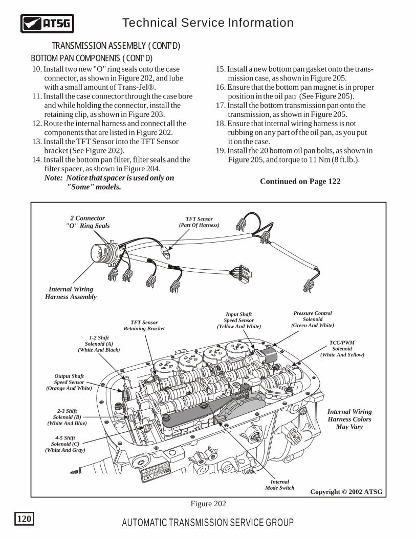
AUTOMATIC TRANSMISSION SERVICE GROUP
Technical Service Information
120
Copyright © 2002 ATSG
BOTTOM PAN COMPONENTS (CONT'D)
TRANSMISSION ASSEMBLY (CONT'D)
10. Install two new "O" ring seals onto the case connector, as shown in Figure 202, and lube with a small amount of Trans-Jel®. 11. Install the case connector through the case bore and while holding the connector, install the retaining clip, as shown in Figure 203. 12. Route the internal harness and connect all the components that are listed in Figure 202. 13. Install the TFT Sensor into the TFT Sensor bracket (See Figure 202). 14. Install the bottom pan filter, filter seals and the filter spacer, as shown in Figure 204. Note: Notice that spacer is used only on "Some" models.
15. Install a new bottom pan gasket onto the trans- mission case, as shown in Figure 205. 16. Ensure that the bottom pan magnet is in proper position in the oil pan (See Figure 205). 17. Install the bottom transmission pan onto the transmission, as shown in Figure 205. 18. Ensure that internal wiring harness is not rubbing on any part of the oil pan, as you put it on the case. 19. Install the 20 bottom oil pan bolts, as shown in Figure 205, and torque to 11 Nm (8 ft.lb.).
HYDRAMATIC
STRASBOURG
MADE IN FRANCESERIAL NO.
1 423 875
0139781 96022832
P08
VO
_ __ _
PART NO.
TCM
CAL.
GM
96020473
96020566
307
Pressure ControlSolenoid
(Green And White)
Input ShaftSpeed Sensor
(Yellow And White)
TFT Sensor(Part Of Harness)
TFT SensorRetaining Bracket
2 Connector"O" Ring Seals
Internal WiringHarness Assembly
Internal WiringHarness Colors
May Vary
Output ShaftSpeed Sensor
(Orange And White)
1-2 ShiftSolenoid (A)
(White And Black)
2-3 ShiftSolenoid (B)
(White And Blue)
4-5 ShiftSolenoid (C)
(White And Gray)
InternalMode Switch
TCC/PWMSolenoid
(White And Yellow)
Figure 202
Continued on Page 122
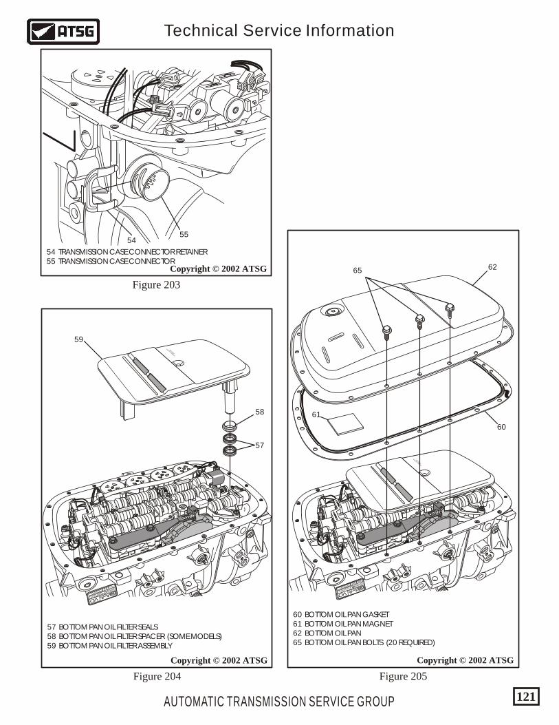
AUTOMATIC TRANSMISSION SERVICE GROUP
Technical Service Information
121
Figure 204
Copyright © 2002 ATSG
HYDRAMATIC
STRASBOURG
MADE IN FRANCESERIAL NO.
1 423 875
0139781 96022832
P08
VO
_ __ _
PART NO.
TCM
CAL.
GM
96020473
96020566
307
IBS FILTRAN
MADE IN G
ERMANY
59
58
57
57 BOTTOM PAN OIL FILTER SEALS 58 BOTTOM PAN OIL FILTER SPACER (SOME MODELS) 59 BOTTOM PAN OIL FILTER ASSEMBLY
Copyright © 2002 ATSG
Figure 203
54 TRANSMISSION CASE CONNECTOR RETAINER 55 TRANSMISSION CASE CONNECTOR
5554
Copyright © 2002 ATSG
Figure 205
HYDRAMATIC
STRASBOURG
MADE IN FRANCESERIAL NO.
1 423 875
0139781 96022832
P08
VO
_ __ _
PART NO.
TCM
CAL.
GM
96020473
96020566
307
IBS FILTRAN
MADE IN G
ERMANY
65 62
60
61
60 BOTTOM OIL PAN GASKET 61 BOTTOM OIL PAN MAGNET 62 BOTTOM OIL PAN 65 BOTTOM OIL PAN BOLTS (20 REQUIRED)
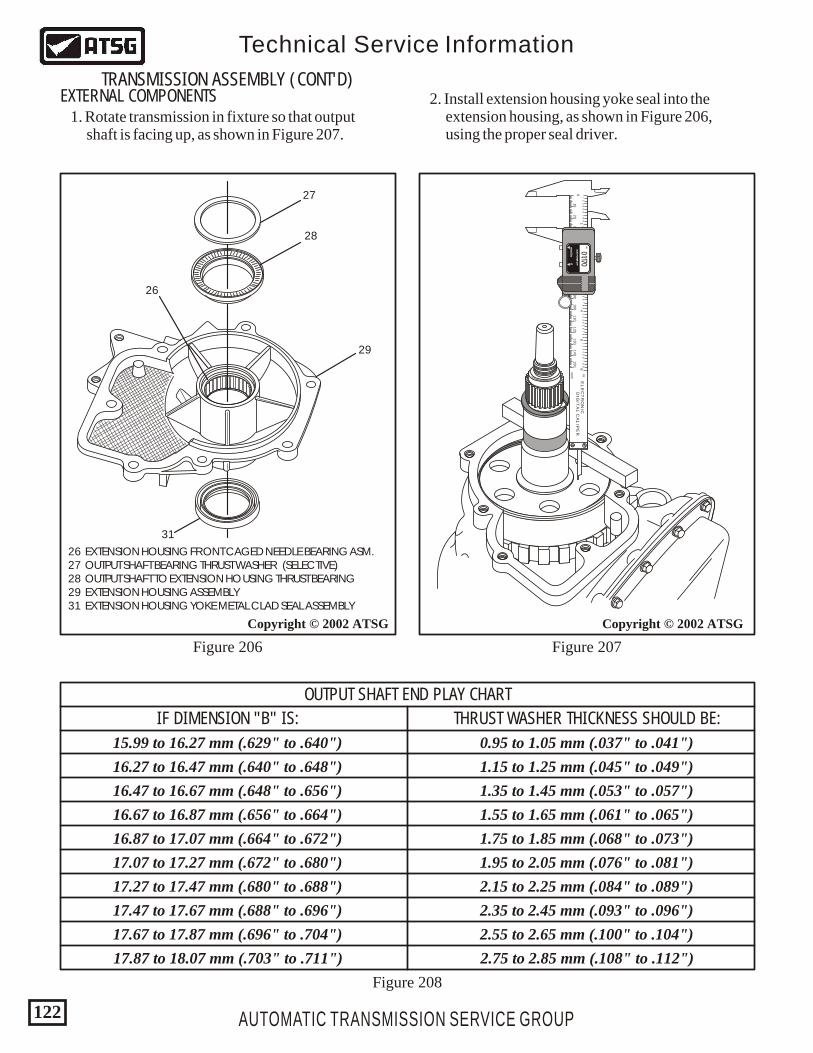
AUTOMATIC TRANSMISSION SERVICE GROUP
Technical Service Information
122
Copyright © 2002 ATSG
Figure 206 Figure 207
Figure 208
Copyright © 2002 ATSG
26 EXTENSION HOUSING FRONT CAGED NEEDLE BEARING ASM. 27 OUTPUT SHAFT BEARING THRUST WASHER (SELECTIVE) 28 OUTPUT SHAFT TO EXTENSION HOUSING THRUST BEARING 29 EXTENSION HOUSING ASSEMBLY 31 EXTENSION HOUSING YOKE METAL CLAD SEAL ASSEMBLY
27
28
29
31
26
43
21
12
34
56
78
91
23
45
67
89
12
34
56
78
91
23
45
67
89
12
34
56
78
91
23
45
67
89
56
10
20
30
40
50
60
70
80
90
150
140
130
120
110
100
0
in
mm
EL
EC
TR
ON
ICD
IGIT
AL
CA
LIP
ER
AU
TO P
OW
ER
-OFF
AU
TO P
OW
ER
-OFF
mm
/inm
m/in
00
01.170IN
OUTPUT SHAFT END PLAY CHART
IF DIMENSION "B" IS: THRUST WASHER THICKNESS SHOULD BE:
15.99 to 16.27 mm (.629" to .640")
16.27 to 16.47 mm (.640" to .648")
16.47 to 16.67 mm (.648" to .656")
16.67 to 16.87 mm (.656" to .664")
16.87 to 17.07 mm (.664" to .672")
17.07 to 17.27 mm (.672" to .680")
17.27 to 17.47 mm (.680" to .688")
17.47 to 17.67 mm (.688" to .696")
17.67 to 17.87 mm (.696" to .704")
17.87 to 18.07 mm (.703" to .711")
0.95 to 1.05 mm (.037" to .041")
1.15 to 1.25 mm (.045" to .049")
1.35 to 1.45 mm (.053" to .057")
1.55 to 1.65 mm (.061" to .065")
1.75 to 1.85 mm (.068" to .073")
1.95 to 2.05 mm (.076" to .081")
2.15 to 2.25 mm (.084" to .089")
2.35 to 2.45 mm (.093" to .096")
2.55 to 2.65 mm (.100" to .104")
2.75 to 2.85 mm (.108" to .112")
EXTERNAL COMPONENTSTRANSMISSION ASSEMBLY (CONT'D)
1. Rotate transmission in fixture so that output shaft is facing up, as shown in Figure 207.
2. Install extension housing yoke seal into the extension housing, as shown in Figure 206, using the proper seal driver.
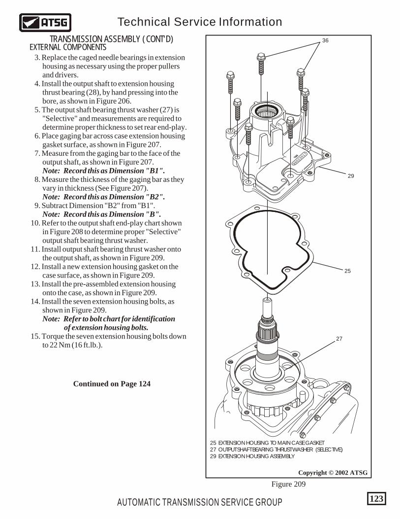
AUTOMATIC TRANSMISSION SERVICE GROUP
Technical Service Information
123
Copyright © 2002 ATSG
25 EXTENSION HOUSING TO MAIN CASE GASKET 27 OUTPUT SHAFT BEARING THRUST WASHER (SELECTIVE) 29 EXTENSION HOUSING ASSEMBLY
Figure 209
96023017GM
36
29
25
27
EXTERNAL COMPONENTSTRANSMISSION ASSEMBLY (CONT'D)
3. Replace the caged needle bearings in extension housing as necessary using the proper pullers and drivers. 4. Install the output shaft to extension housing thrust bearing (28), by hand pressing into the bore, as shown in Figure 206. 5. The output shaft bearing thrust washer (27) is "Selective" and measurements are required to determine proper thickness to set rear end-play. 6. Place gaging bar across case extension housing gasket surface, as shown in Figure 207. 7. Measure from the gaging bar to the face of the output shaft, as shown in Figure 207. Note: Record this as Dimension "B1". 8. Measure the thickness of the gaging bar as they vary in thickness (See Figure 207). Note: Record this as Dimension "B2". 9. Subtract Dimension "B2" from "B1". Note: Record this as Dimension "B". 10. Refer to the output shaft end-play chart shown in Figure 208 to determine proper "Selective" output shaft bearing thrust washer. 11. Install output shaft bearing thrust washer onto the output shaft, as shown in Figure 209. 12. Install a new extension housing gasket on the case surface, as shown in Figure 209. 13. Install the pre-assembled extension housing onto the case, as shown in Figure 209. 14. Install the seven extension housing bolts, as shown in Figure 209. Note: Refer to bolt chart for identification of extension housing bolts. 15. Torque the seven extension housing bolts down to 22 Nm (16 ft.lb.).
Continued on Page 124
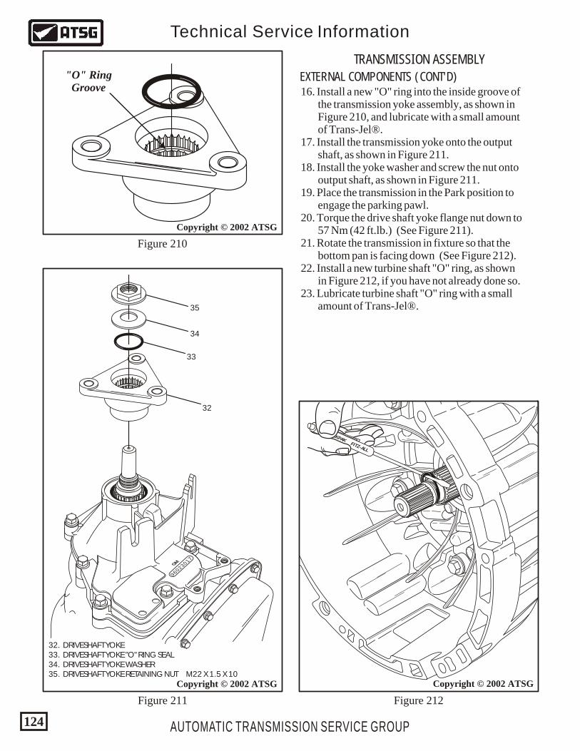
AUTOMATIC TRANSMISSION SERVICE GROUP
Technical Service Information
124
16. Install a new "O" ring into the inside groove of the transmission yoke assembly, as shown in Figure 210, and lubricate with a small amount of Trans-Jel®. 17. Install the transmission yoke onto the output shaft, as shown in Figure 211. 18. Install the yoke washer and screw the nut onto output shaft, as shown in Figure 211. 19. Place the transmission in the Park position to engage the parking pawl. 20. Torque the drive shaft yoke flange nut down to 57 Nm (42 ft.lb.) (See Figure 211). 21. Rotate the transmission in fixture so that the bottom pan is facing down (See Figure 212). 22. Install a new turbine shaft "O" ring, as shown in Figure 212, if you have not already done so. 23. Lubricate turbine shaft "O" ring with a small amount of Trans-Jel®.
32. DRIVESHAFT YOKE 33. DRIVESHAFT YOKE "O" RING SEAL 34. DRIVESHAFT YOKE WASHER 35. DRIVESHAFT YOKE RETAINING NUT M22 X 1.5 X 10
96023017GM
Copyright © 2002 ATSG
Figure 211
32
33
34
35
Copyright © 2002 ATSG
Figure 210
"O" RingGroove
Figure 212
TECKPAKFITZ-ALL
Copyright © 2002 ATSG
TRANSMISSION ASSEMBLY
EXTERNAL COMPONENTS (CONT'D)
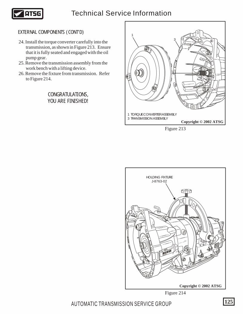
AUTOMATIC TRANSMISSION SERVICE GROUP
Technical Service Information
125
Copyright © 2002 ATSG
1
3
1 TORQUE CONVERTER ASSEMBLY 3 TRANSMISSION ASSEMBLY
Copyright © 2002 ATSG
Figure 214
Figure 213
GMHYDRAMATIC
STRASBOURG
FRANCEHYDRAMATIC
STRASBOURG
FRANCE
*0139781RVO*
*0139781RVO*
96 02296 022 832
18/12/99 019971
18:54
1423875
P08
0139978196022832
VO
GMGM
HOLDING FIXTUREJ-8763-02
24. Install the torque converter carefully into the transmission, as shown in Figure 213. Ensure that it is fully seated and engaged with the oil pump gear. 25. Remove the transmission assembly from the work bench with a lifting device. 26. Remove the fixture from transmission. Refer to Figure 214.
EXTERNAL COMPONENTS (CONT'D)
CONGRATULATIONS,YOU ARE FINISHED!
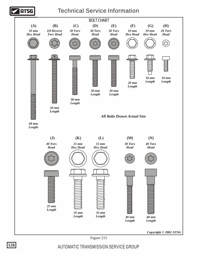
BOLT CHART
10 mmHex Head
68 mmLength
50 mmLength
E8 ReverseTorx Head
38 mmLength
30 TorxHead
30 mmLength
30 TorxHead
30 mmLength
30 TorxHead
40 mmLength
30 TorxHead
40 mmLength
40 TorxHead
35 mmLength
15 mmHex Head
35 mmLength
15 mmHex Head
10 mmHex Head
20 mmLength
10 mmHex Head
10 mmLength
25 mmLength
40 TorxHead
10 mmLength
20 TorxHead
AUTOMATIC TRANSMISSION SERVICE GROUP
Technical Service Information
126
Copyright © 2002 ATSG
Figure 215
(A) (B) (C) (D) (E) (F) (G) (H)
(J) (K) (L) (M) (N)
All Bolts Drawn Actual Size
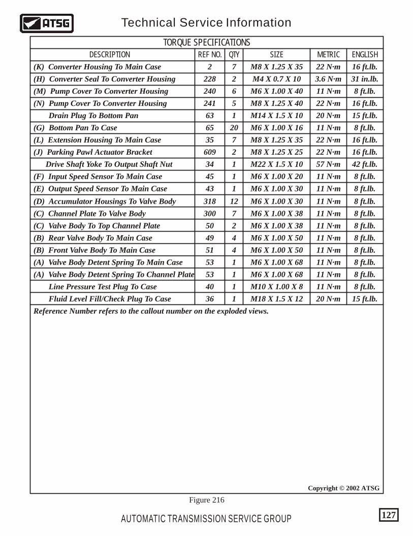
AUTOMATIC TRANSMISSION SERVICE GROUP
Technical Service Information
127
Copyright © 2002 ATSG
TORQUE SPECIFICATIONSDESCRIPTION QTYREF NO. SIZE METRIC ENGLISH
(N) Pump Cover To Converter Housing
Line Pressure Test Plug To Case
Fluid Level Fill/Check Plug To Case
Reference Number refers to the callout number on the exploded views.
(M) Pump Cover To Converter Housing
(C) Valve Body To Top Channel Plate
(B) Rear Valve Body To Main Case
(B) Front Valve Body To Main Case
(A) Valve Body Detent Spring To Main Case
(A) Valve Body Detent Spring To Channel Plate
(D) Accumulator Housings To Valve Body
(C) Channel Plate To Valve Body
(K) Converter Housing To Main Case
(H) Converter Seal To Converter Housing
(L) Extension Housing To Main Case
(J) Parking Pawl Actuator Bracket
Drive Shaft Yoke To Output Shaft Nut
(F) Input Speed Sensor To Main Case
(E) Output Speed Sensor To Main Case
Drain Plug To Bottom Pan
(G) Bottom Pan To Case
12
7
7
7
1
1
1
20
8 ft.lb.
8 ft.lb.
8 ft.lb.
8 ft.lb.
8 ft.lb.
8 ft.lb.
8 ft.lb.
8 ft.lb.
8 ft.lb.
8 ft.lb.
8 ft.lb.
8 ft.lb.
16 ft.lb.
16 ft.lb.
42 ft.lb.
31 in.lb.
16 ft.lb.
16 ft.lb.
15 ft.lb.
15 ft.lb.
11 N·m
11 N·m
11 N·m
11 N·m
11 N·m
11 N·m
11 N·m
11 N·m
11 N·m
11 N·m
11 N·m
11 N·m
22 N·m
22 N·m
57 N·m
3.6 N·m
22 N·m
22 N·m
20 N·m
20 N·m
5
6
2
4
4
1
1
1
1
2
2
1
318
300
2
63
65
35
45
43
34
609
228
50
49
51
53
53
40
36
241
240
M6 X 1.00 X 30
M6 X 1.00 X 20
M6 X 1.00 X 30
M6 X 1.00 X 38
M6 X 1.00 X 50
M6 X 1.00 X 50
M6 X 1.00 X 68
M6 X 1.00 X 68
M10 X 1.00 X 8
M18 X 1.5 X 12
M6 X 1.00 X 40
M6 X 1.00 X 16
M6 X 1.00 X 38
M4 X 0.7 X 10
M8 X 1.25 X 40
M8 X 1.25 X 35
M8 X 1.25 X 25
M8 X 1.25 X 35
M14 X 1.5 X 10
M22 X 1.5 X 10
Figure 216
AUTOMATIC TRANSMISSION SERVICE GROUP
Technical Service Information
128
Copyright © 2002 ATSG
We wish to thank the following for supplying the actualtransmission that have made these illustrations possible.
5846 SW 68TH STREETSOUTH MIAMI, FLORIDA 33143
INDEPENDENT TRANSMISSION SERVICEINDEPENDENT TRANSMISSION SERVICEAND MARIO ARISTIDESAND MARIO ARISTIDES
Phone (305) 666-3544Phone (305) 666-4208Fax (305) 666-8238