bnct system using 30 mev h- cyclotron -...
TRANSCRIPT
BNCT SYSTEM USING 30 MEV H- CYCLOTRON
T. Mitsumoto, K. Fujita, T. Ogasawara, H. Tsutsui, S. Yajima, Sumitomo Heavy Industries, Ltd., Tokyo, Japan
A. Maruhashi, Y. Sakurai, H. Tanaka, Kyoto University Research Reactor Institute, Osaka, Japan
Abstract Kyoto University and Sumitomo Heavy Industries, Ltd.
(SHI) have developed an accelerator-based neutron source for Boron Neutron Capture Therapy (BNCT) at the Kyoto University Research Reactor Institute (KURRI). In order to obtain 109 n/cm2/sec epithermal neutrons for cancer treatment, a newly designed 30 MeV H- AVF cyclotron named HM-30 was constructed and is being operated. With newly developed spiral inflector, the beam current in the central region can exceed 2 mA. The cyclotron is operated stably at 1 mA. Extracted proton beam is expanded by two scanner magnets in order to moderate heat concentration on the beryllium target, which is directly cooled by water to endure 30 kW heat load. Fast neutrons are emitted from the target, and moderated to epithermal region by a moderator which consists of lead, iron, polyethylene, etc. Thermal neutron flux in a water phantom is measured by gold wire, which is consistent with the calculation using MCNPX. Preclinical studies are being carried out with 10B-p-Borono- phenylalanine (BPA).
INTRODUCTION In BNCT [1], 10B is selectively taken into the malignant
tissues by suitable boron delivery agent such as BPA and sodium borocaptate (BSH). Exposure of thermal neutron flux generates energetic alpha particles and 7Li nuclei, which kill the malignant tissues at the cellular level.
For clinical research of BNCT, thermal neutrons have been provided mainly by nuclear reactors [2,3]. Since it is inappropriate to install nuclear reactors in hospitals, many kinds of accelerator based neutron sources have been considered [4,5,6].
One approach is combination of a high current (~100 mA) low energy (~2.5 MeV) proton accelerator and a lithium target [4]. With this combination, fast neutron yield in the target is 1×10¹⁴ n/sec, for irradiating 2×10⁹ n/cm2/sec thermal neutrons in tumor.
A serious problem of this approach is that the heat load in the lithium target (~250 kW) is too high. Using a lower beam current (~2.8 MeV, ~20mA) has been proposed [5,6]. This approach sacrifices the neutron yield, nevertheless the heat load is still around 60 kW, and it is too high for the lithium target.
Another approach is to use a middle energy (10~50 MeV) high current (1~3 mA) proton cyclotron and a beryllium target. With a 30 MeV proton cyclotron, 1.9×10¹⁴ n/sec fast neutrons can be obtained at 1 mA, but the heat load is only 30 kW.
KURRI and SHI started developing the accelerator based neutron source for BNCT in 2007. In order to get high flux neutrons, we selected a combination of the 30
MeV proton beam and the beryllium target. A new AVF cyclotron named HM-30 was designed to generate 30 MeV proton beam with the maximum current of 2 mA.
At the same time, an irradiation system was also designed. Since the thermal neutron does not reach the inner part of a human body, the application of epithermal neutron (0.5 eV ~ 40 keV, in our definition) is more preferable. An epithermal neutron irradiation system optimized for the 30 MeV proton beam was designed with MCNPX [7].
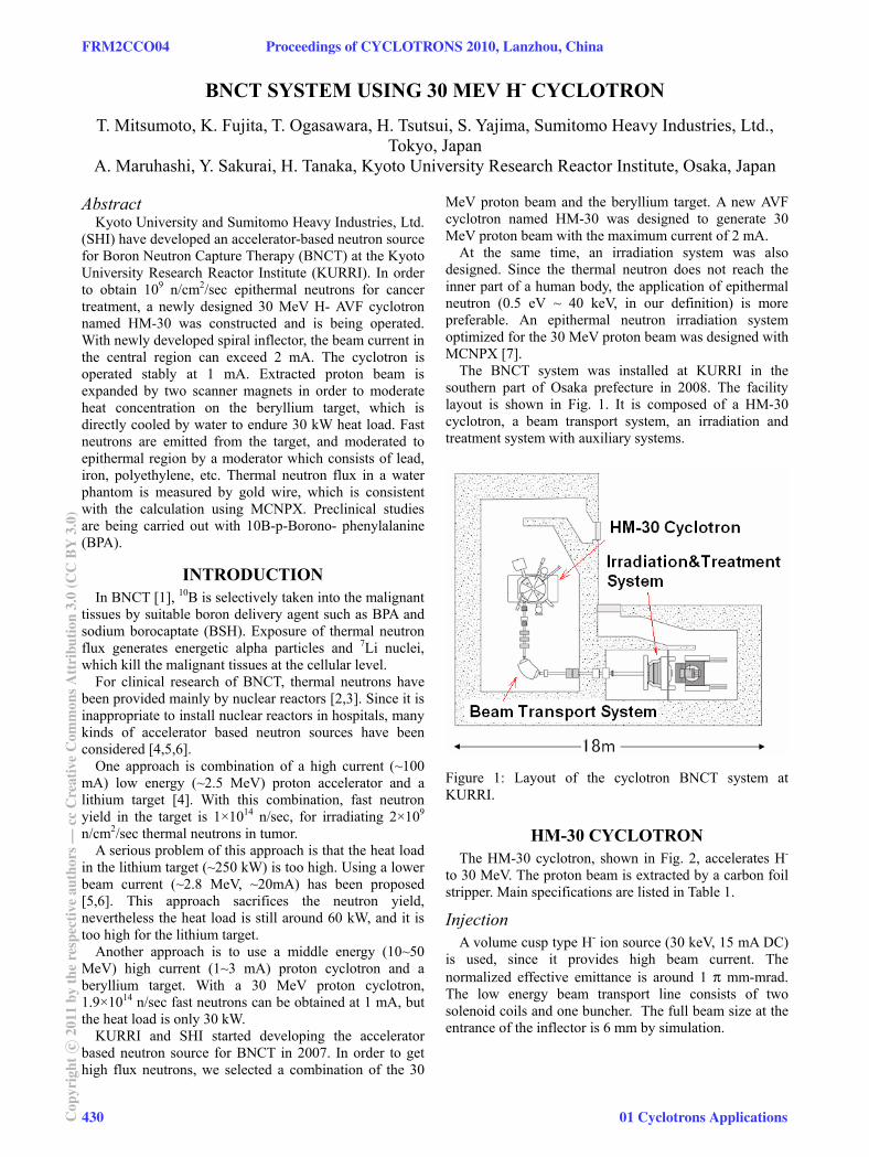
The BNCT system was installed at KURRI in the southern part of Osaka prefecture in 2008. The facility layout is shown in Fig. 1. It is composed of a HM-30 cyclotron, a beam transport system, an irradiation and treatment system with auxiliary systems.
Figure 1: Layout of the cyclotron BNCT system at KURRI.
HM-30 CYCLOTRON The HM-30 cyclotron, shown in Fig. 2, accelerates H-
to 30 MeV. The proton beam is extracted by a carbon foil stripper. Main specifications are listed in Table 1.
Injection A volume cusp type H- ion source (30 keV, 15 mA DC)
is used, since it provides high beam current. The normalized effective emittance is around 1 π mm-mrad. The low energy beam transport line consists of two solenoid coils and one buncher. The full beam size at the entrance of the inflector is 6 mm by simulation.
FRM2CCO04 Proceedings of CYCLOTRONS 2010, Lanzhou, China
430Cop
yrig
htc ○
2011
byth
ere
spec
tive
auth
ors—
ccC
reat
ive
Com
mon
sAtt
ribu
tion
3.0
(CC
BY
3.0)
01 Cyclotrons Applications
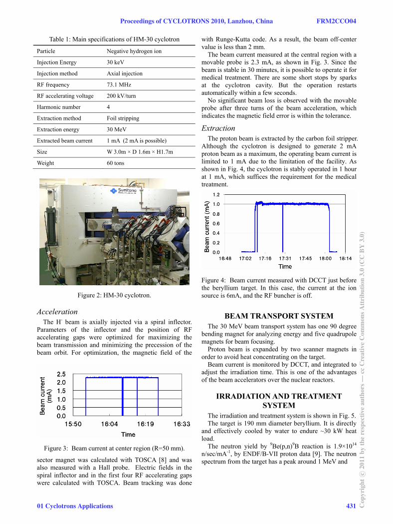
Table 1: Main specifications of HM-30 cyclotron
Particle Negative hydrogen ion
Injection Energy 30 keV
Injection method Axial injection
RF frequency 73.1 MHz
RF accelerating voltage 200 kV/turn
Harmonic number 4
Extraction method Foil stripping
Extraction energy 30 MeV
Extracted beam current 1 mA (2 mA is possible)
Size W 3.0m × D 1.6m × H1.7m
Weight 60 tons
Figure 2: HM-30 cyclotron.
Acceleration The H- beam is axially injected via a spiral inflector.
Parameters of the inflector and the position of RF accelerating gaps were optimized for maximizing the beam transmission and minimizing the precession of the beam orbit. For optimization, the magnetic field of the
sector magnet was calculated with TOSCA [8] and was also measured with a Hall probe. Electric fields in the spiral inflector and in the first four RF accelerating gaps were calculated with TOSCA. Beam tracking was done
with Runge-Kutta code. As a result, the beam off-center value is less than 2 mm.
The beam current measured at the central region with a movable probe is 2.3 mA, as shown in Fig. 3. Since the beam is stable in 30 minutes, it is possible to operate it for medical treatment. There are some short stops by sparks at the cyclotron cavity. But the operation restarts automatically within a few seconds.
No significant beam loss is observed with the movable probe after three turns of the beam acceleration, which indicates the magnetic field error is within the tolerance.
Extraction The proton beam is extracted by the carbon foil stripper.
Although the cyclotron is designed to generate 2 mA proton beam as a maximum, the operating beam current is limited to 1 mA due to the limitation of the facility. As shown in Fig. 4, the cyclotron is stably operated in 1 hour at 1 mA, which suffices the requirement for the medical treatment.
Figure 4: Beam current measured with DCCT just before the beryllium target. In this case, the current at the ion source is 6mA, and the RF buncher is off.
BEAM TRANSPORT SYSTEM The 30 MeV beam transport system has one 90 degree
bending magnet for analyzing energy and five quadrupole magnets for beam focusing.
Proton beam is expanded by two scanner magnets in order to avoid heat concentrating on the target.
Beam current is monitored by DCCT, and integrated to adjust the irradiation time. This is one of the advantages of the beam accelerators over the nuclear reactors.
IRRADIATION AND TREATMENT SYSTEM
The irradiation and treatment system is shown in Fig. 5. The target is 190 mm diameter beryllium. It is directly
and effectively cooled by water to endure ~30 kW heat load.
The neutron yield by 9Be(p,n)9B reaction is 1.9×10¹⁴ n/sec/mA-1, by ENDF/B-VII proton data [9]. The neutron spectrum from the target has a peak around 1 MeV and
Figure 3: Beam current at center region (R=50 mm).
Proceedings of CYCLOTRONS 2010, Lanzhou, China FRM2CCO04
01 Cyclotrons Applications 431 Cop
yrig
htc ○
2011
byth
ere
spec
tive
auth
ors—
ccC
reat
ive
Com
mon
sAtt
ribu
tion
3.0
(CC
BY
3.0)
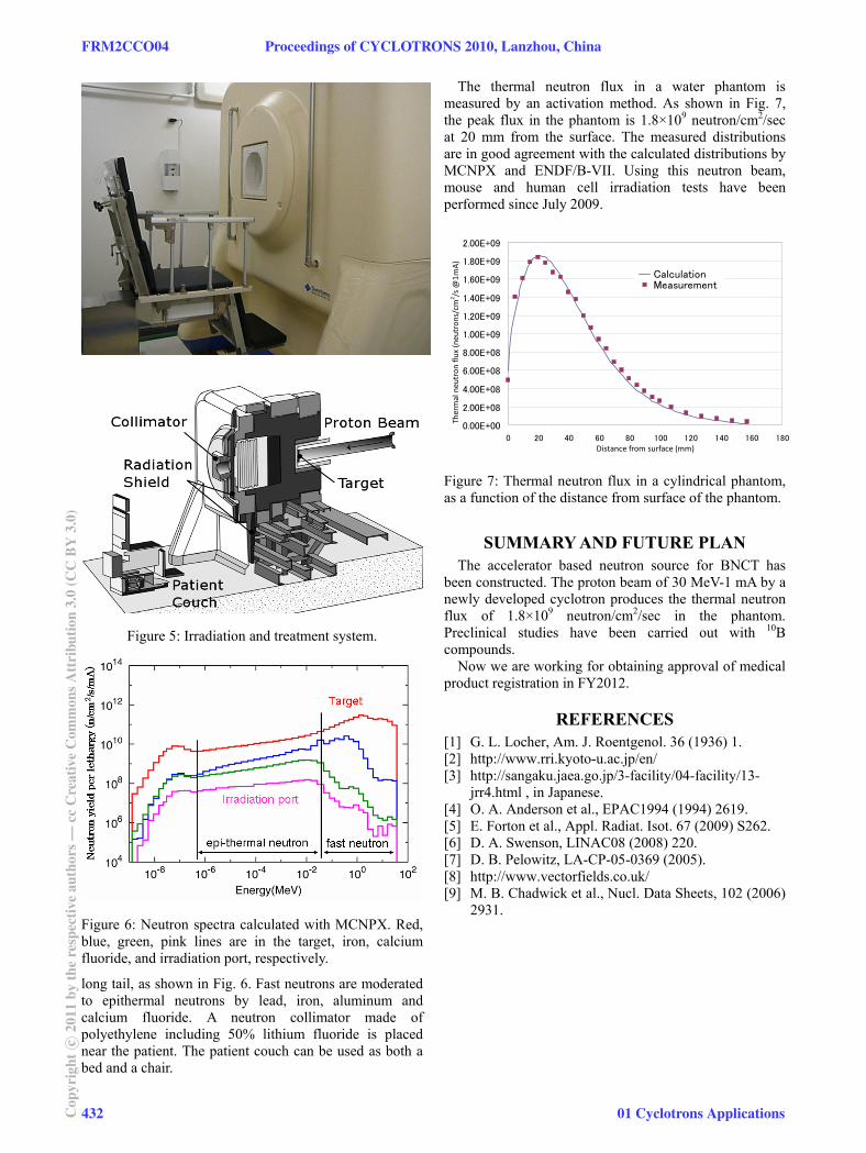
Figure 6: Neutron spectra calculated with MCNPX. Red, blue, green, pink lines are in the target, iron, calcium fluoride, and irradiation port, respectively.
long tail, as shown in Fig. 6. Fast neutrons are moderated to epithermal neutrons by lead, iron, aluminum and calcium fluoride. A neutron collimator made of polyethylene including 50% lithium fluoride is placed near the patient. The patient couch can be used as both a bed and a chair.
The thermal neutron flux in a water phantom is measured by an activation method. As shown in Fig. 7, the peak flux in the phantom is 1.8×10⁹ neutron/cm2/sec at 20 mm from the surface. The measured distributions are in good agreement with the calculated distributions by MCNPX and ENDF/B-VII. Using this neutron beam, mouse and human cell irradiation tests have been performed since July 2009.
0.00E+00
2.00E+08
4.00E+08
6.00E+08
8.00E+08
1.00E+09
1.20E+09
1.40E+09
1.60E+09
1.80E+09
2.00E+09
0 20 40 60 80 100 120 140 160 180Distance from surface (mm)
Ther
mal
neu
tron
flux
(neu
tron
s/cm
2 /s @
1mA
)
CalculationMeasurement
Figure 7: Thermal neutron flux in a cylindrical phantom, as a function of the distance from surface of the phantom.
SUMMARY AND FUTURE PLAN The accelerator based neutron source for BNCT has
been constructed. The proton beam of 30 MeV-1 mA by a newly developed cyclotron produces the thermal neutron flux of 1.8×10⁹ neutron/cm2/sec in the phantom. Preclinical studies have been carried out with 10B compounds.
Now we are working for obtaining approval of medical product registration in FY2012.
REFERENCES [1] G. L. Locher, Am. J. Roentgenol. 36 (1936) 1. [2] http://www.rri.kyoto-u.ac.jp/en/ [3] http://sangaku.jaea.go.jp/3-facility/04-facility/13-
jrr4.html , in Japanese. [4] O. A. Anderson et al., EPAC1994 (1994) 2619. [5] E. Forton et al., Appl. Radiat. Isot. 67 (2009) S262. [6] D. A. Swenson, LINAC08 (2008) 220. [7] D. B. Pelowitz, LA-CP-05-0369 (2005). [8] http://www.vectorfields.co.uk/ [9] M. B. Chadwick et al., Nucl. Data Sheets, 102 (2006)
2931.
Figure 5: Irradiation and treatment system.
FRM2CCO04 Proceedings of CYCLOTRONS 2010, Lanzhou, China
432Cop
yrig
htc ○
2011
byth
ere
spec
tive
auth
ors—
ccC
reat
ive
Com
mon
sAtt
ribu
tion
3.0
(CC
BY
3.0)
01 Cyclotrons Applications